March 22, 2003
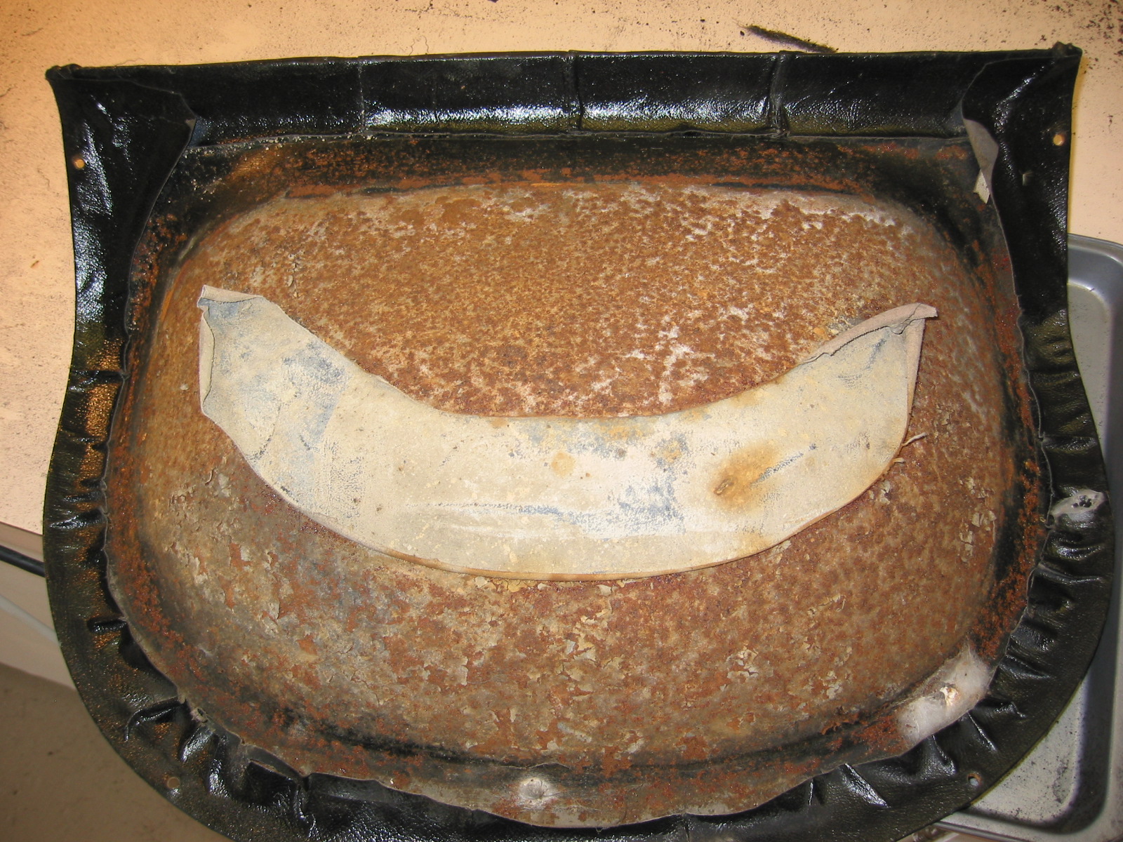
Rear Seats
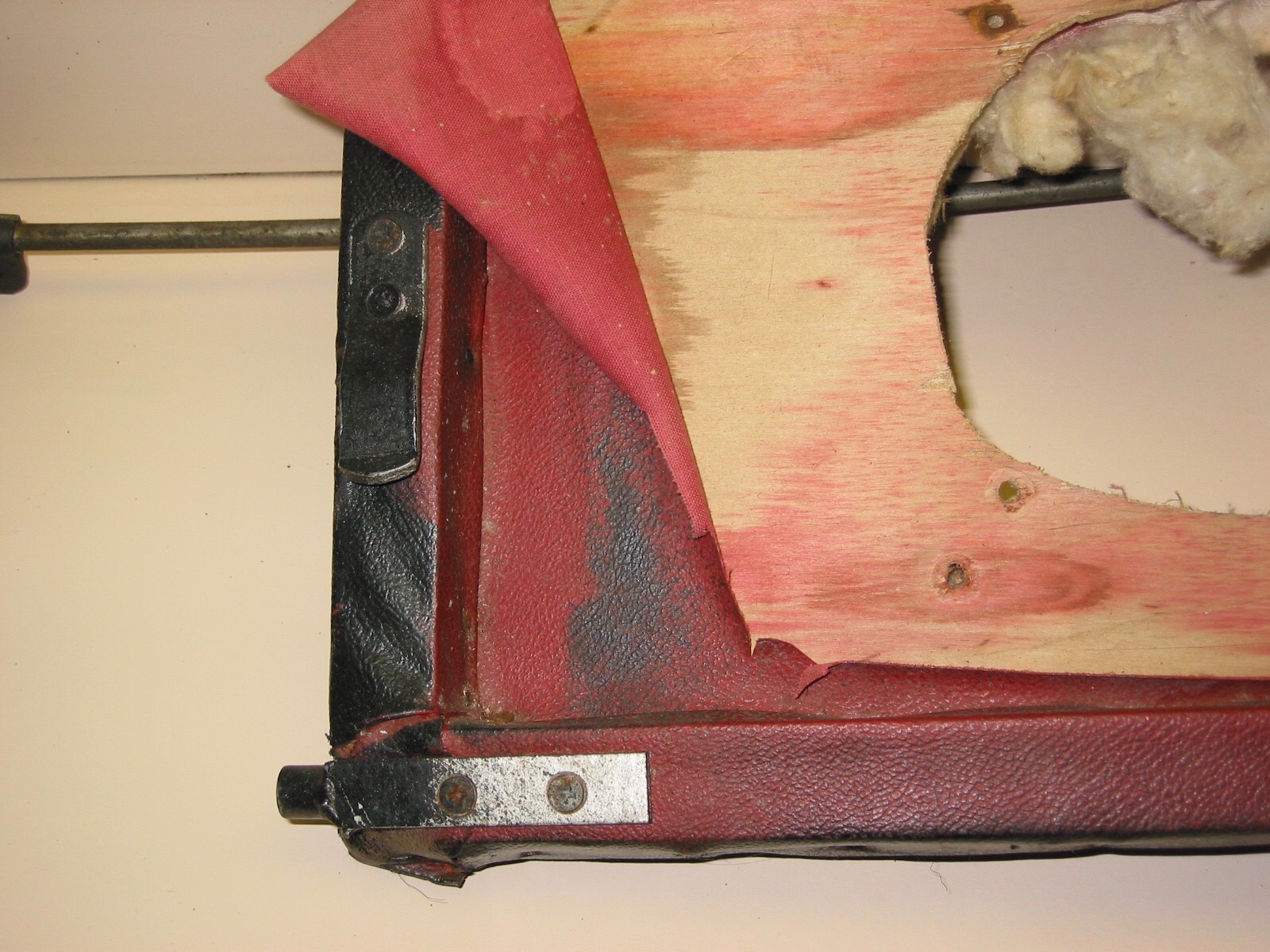
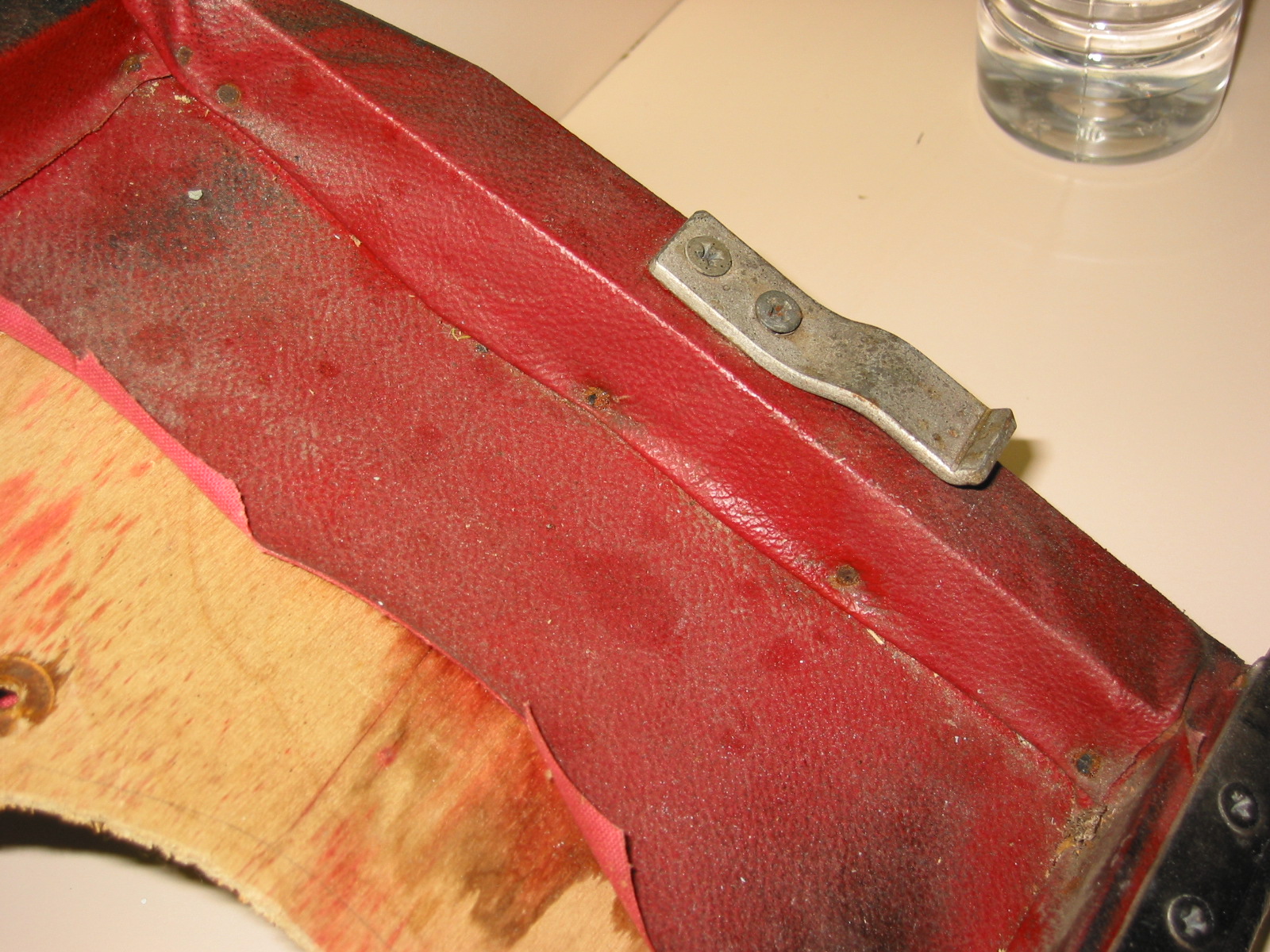
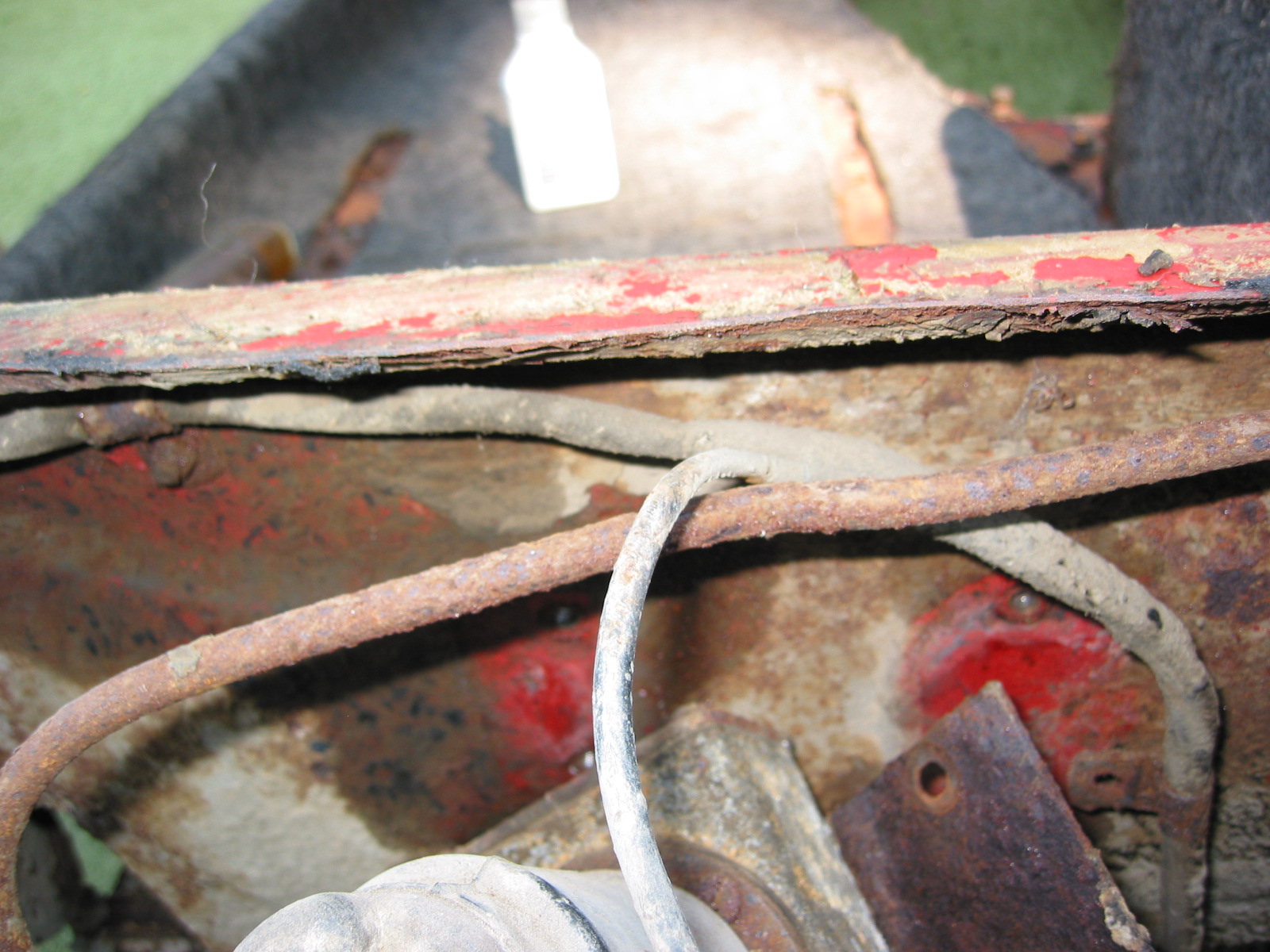
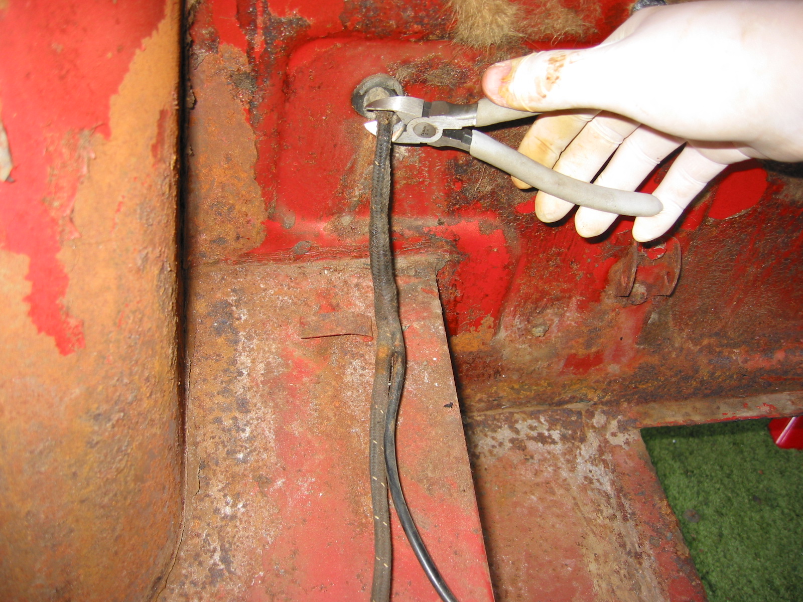
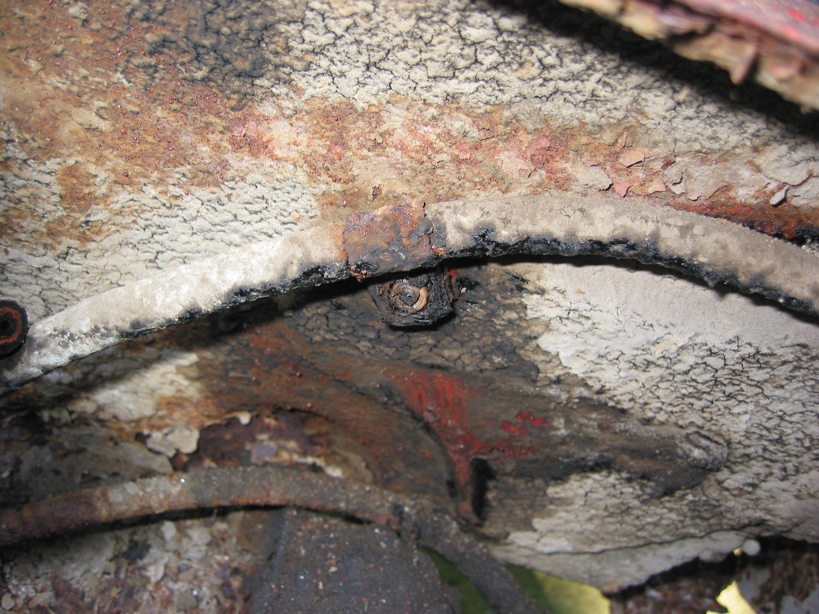
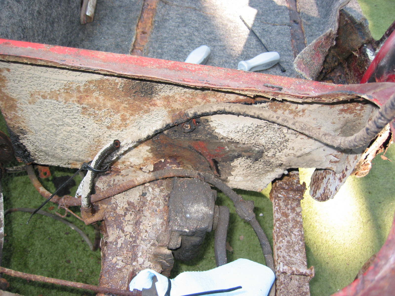
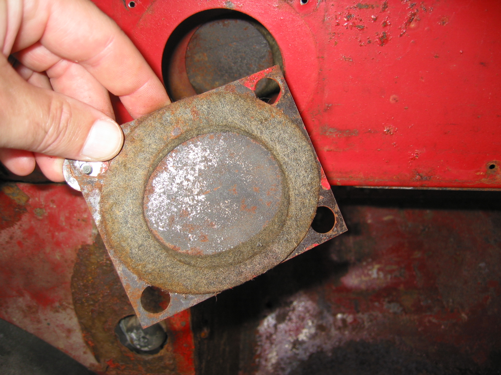
The rear seat pans were very rusty and pitted to some degree, but given that they are completely covered by upholstery we decided to reuse them. The bottom exposed side of the seats was painted with a rubberized undercoating paint.
Rear Seats 1

Rear Seats 3
May 16, 2003
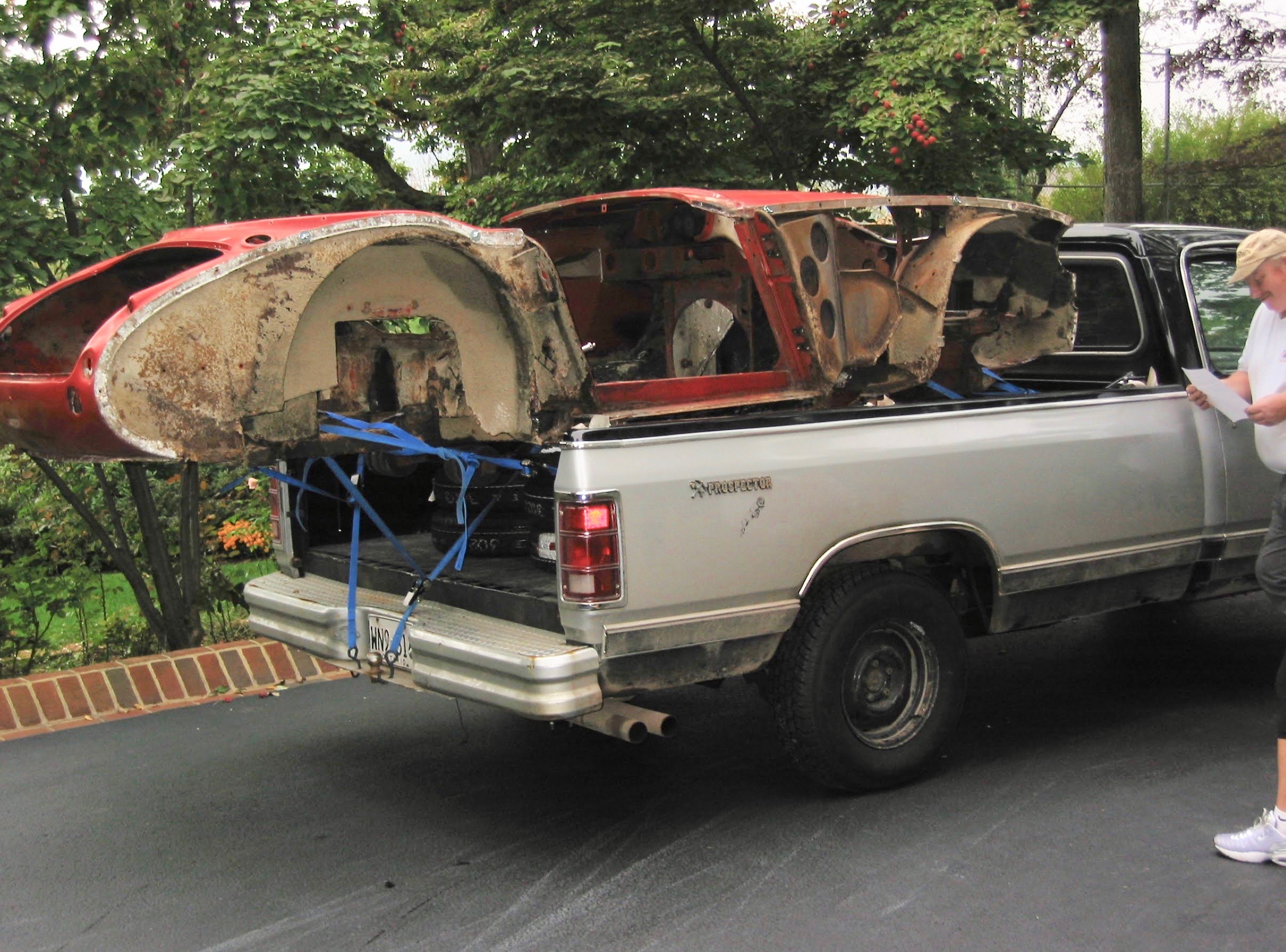
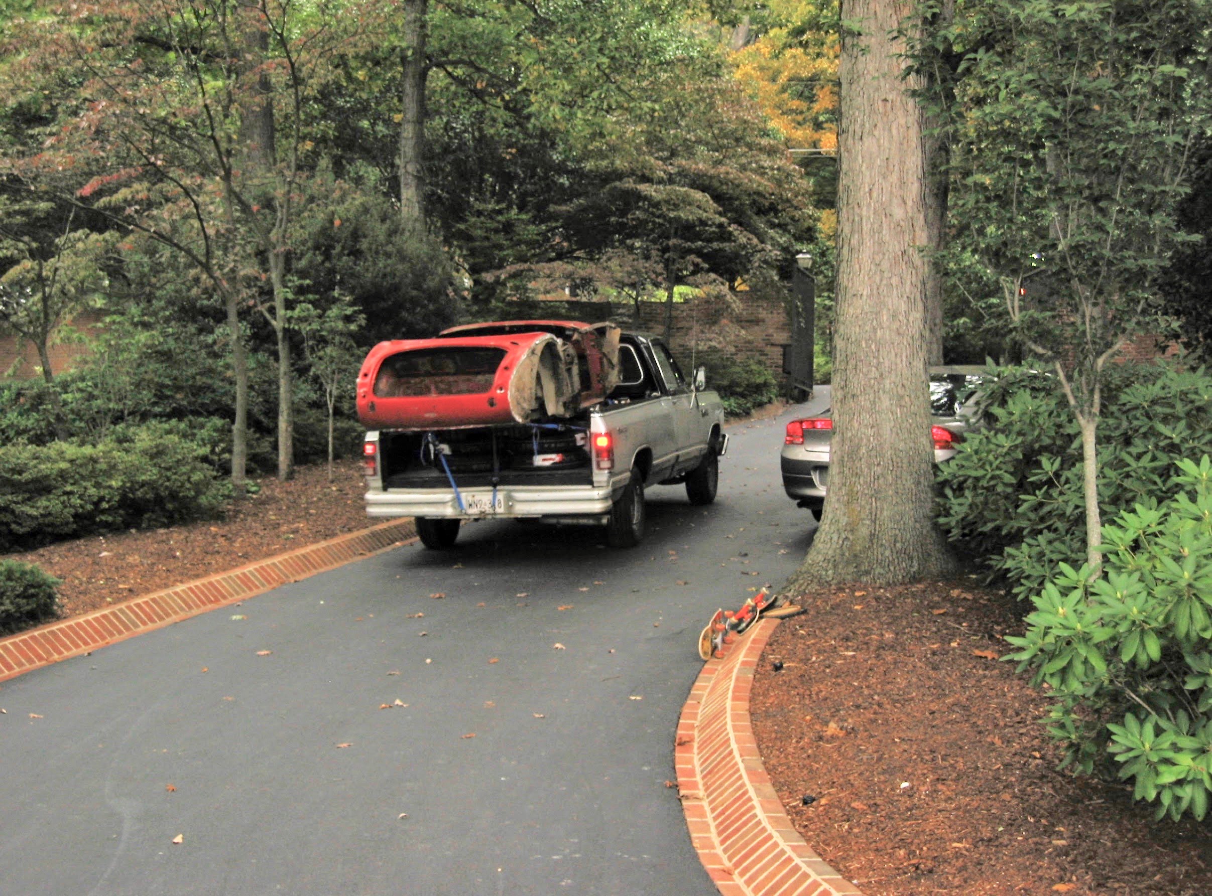
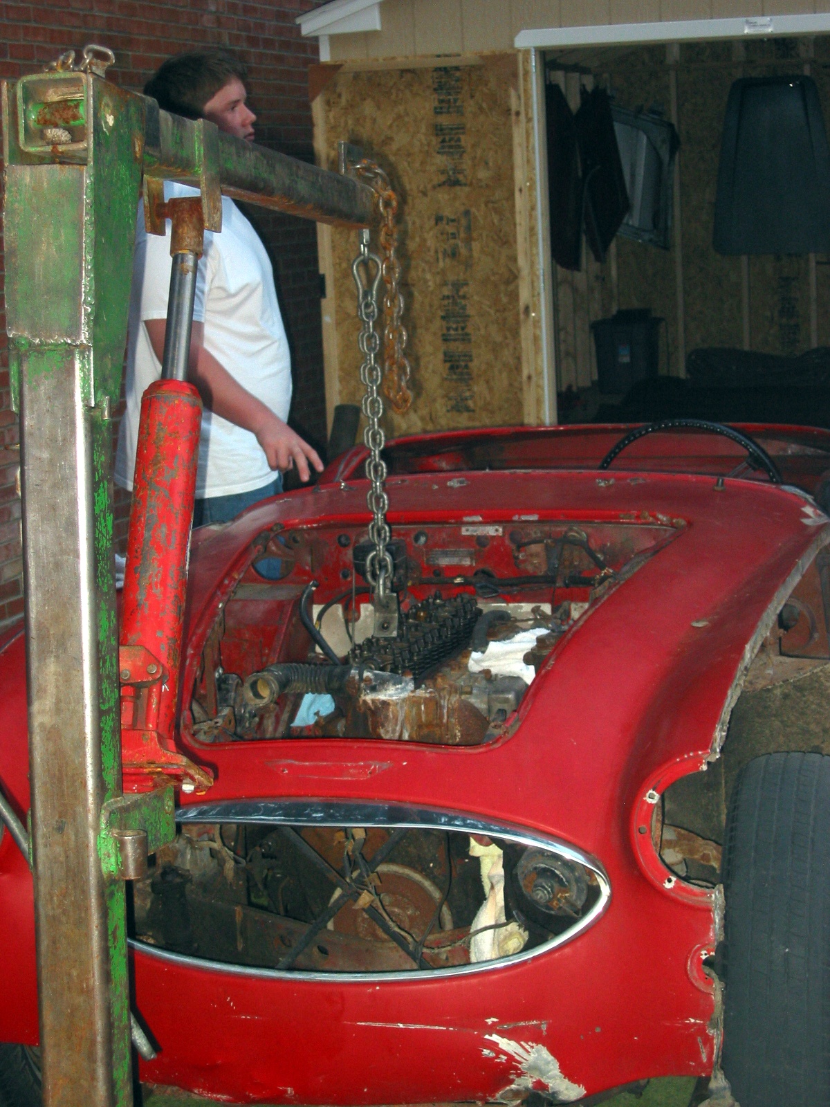
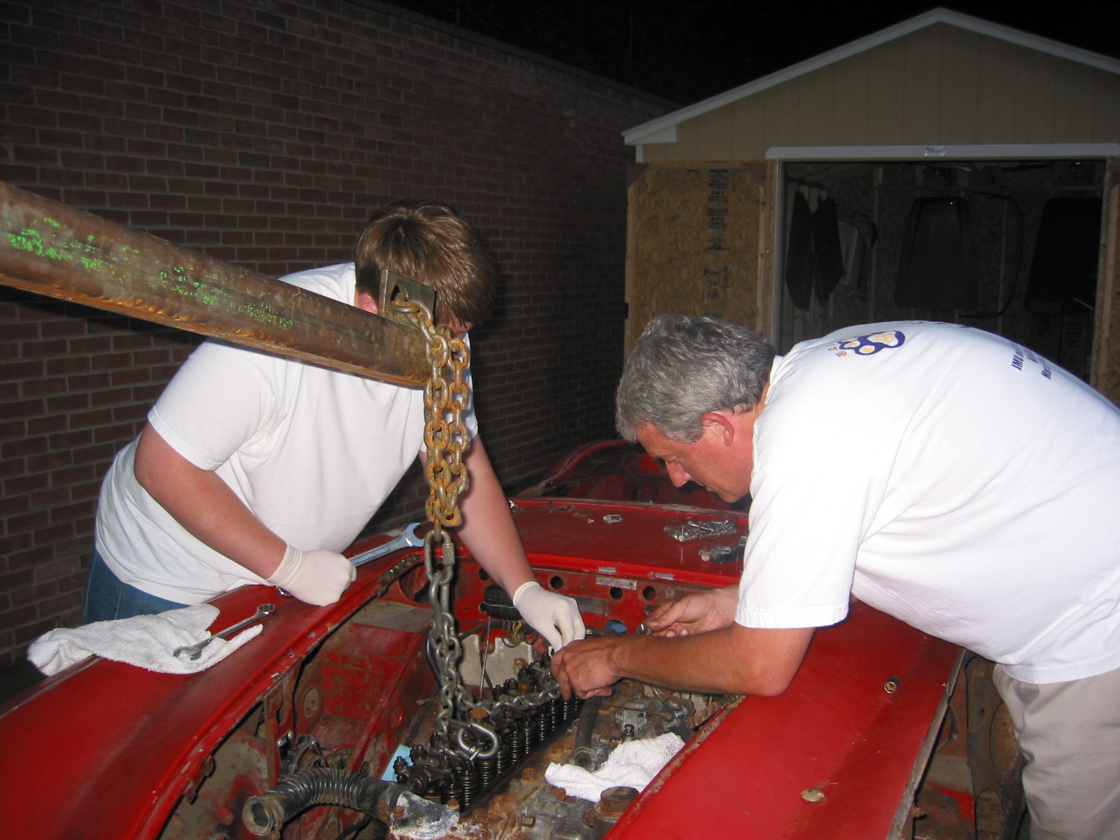
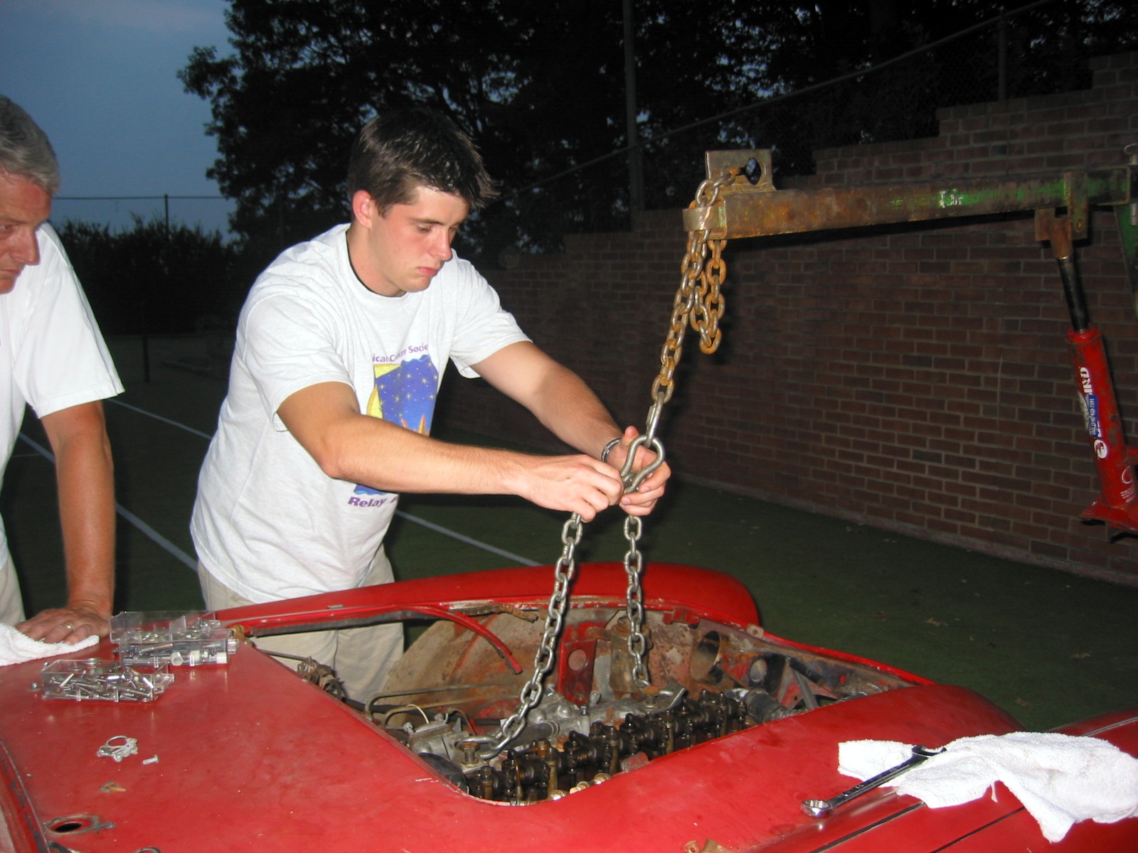
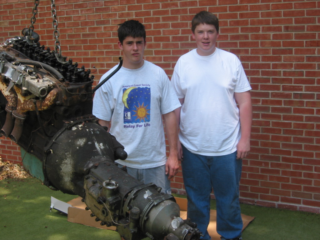
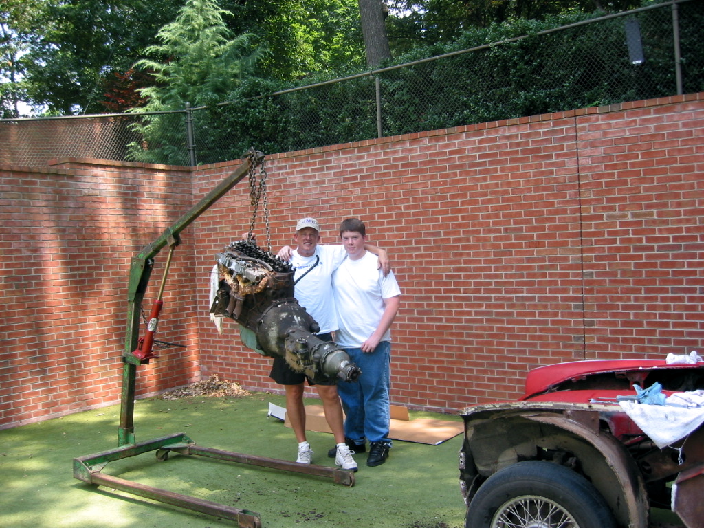
Canadian Delivery!
Martin Jansen delivered the healey from his shop in Canada on the back of his pickup truck! Big day!

May 16 Arrival Day from Martin 1
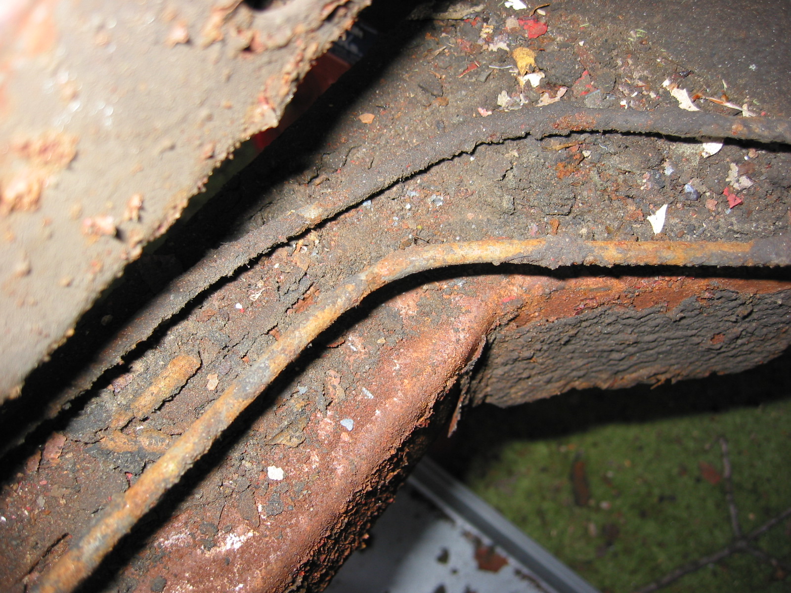
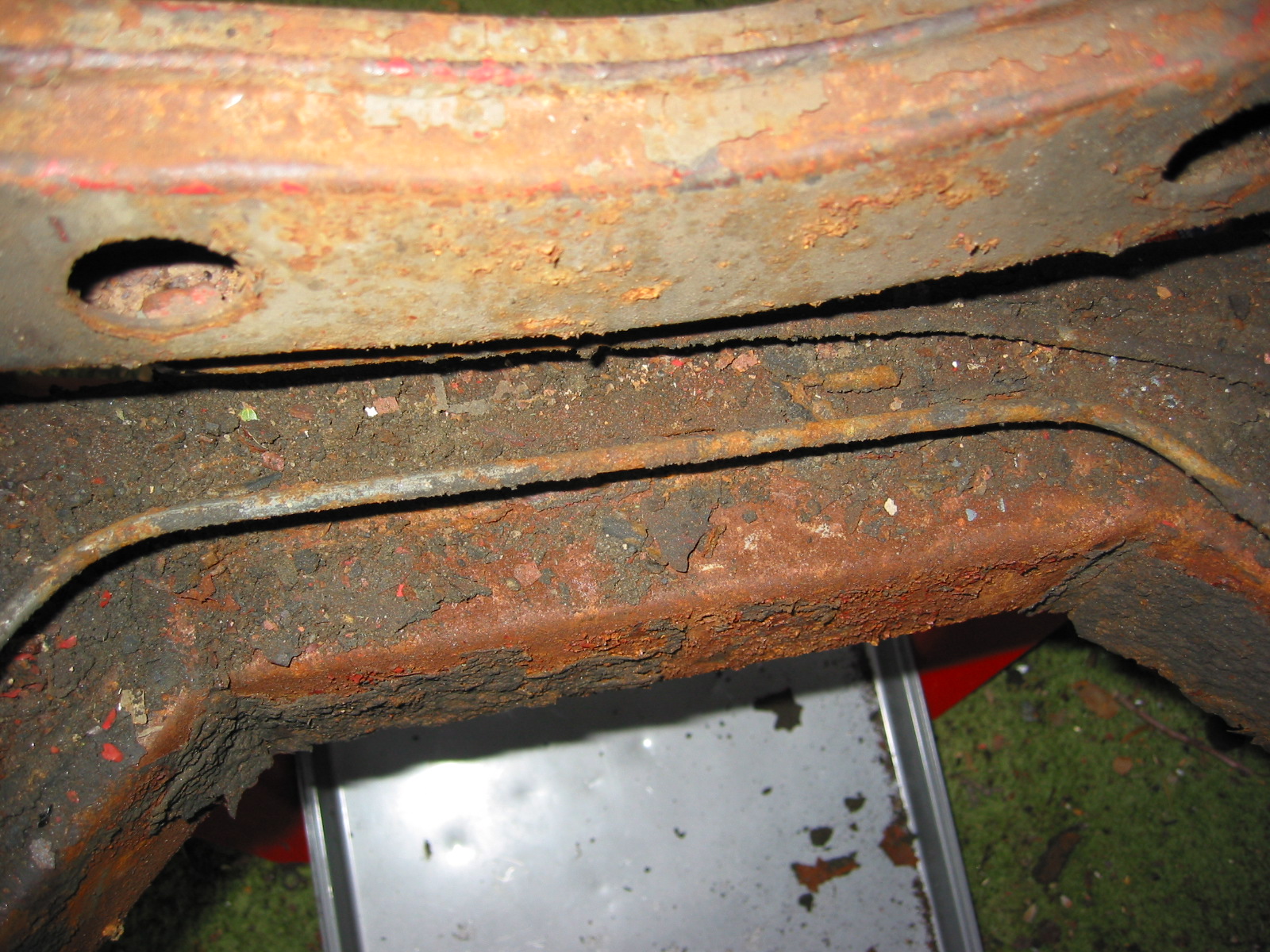
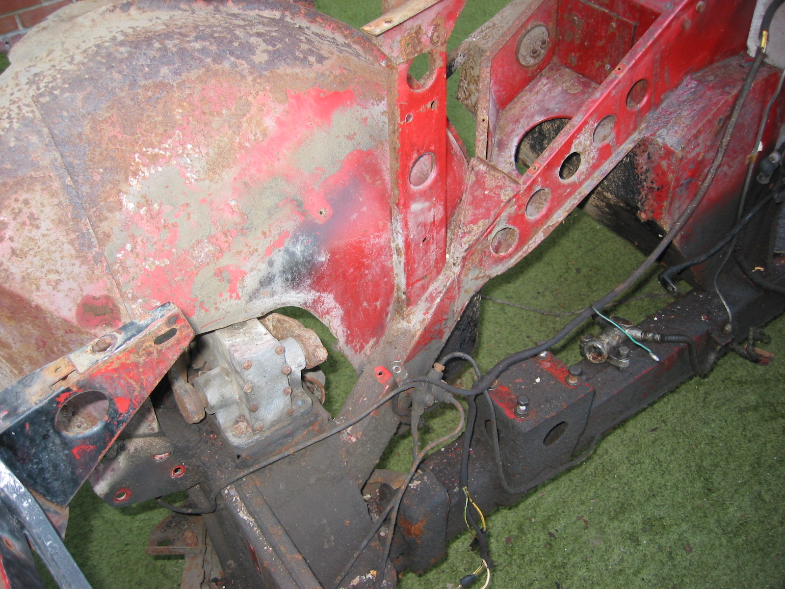
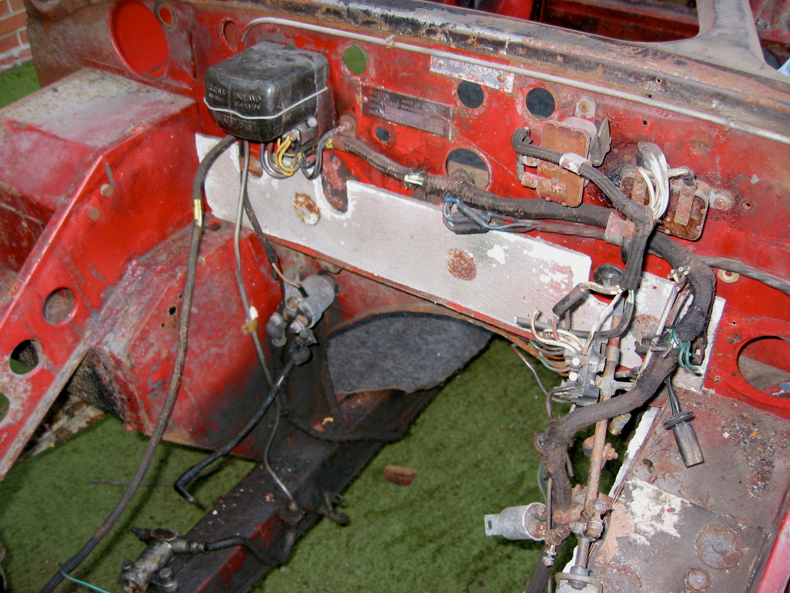
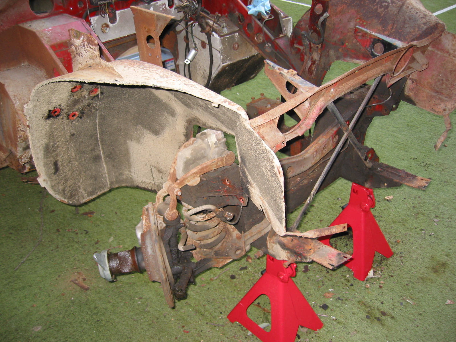
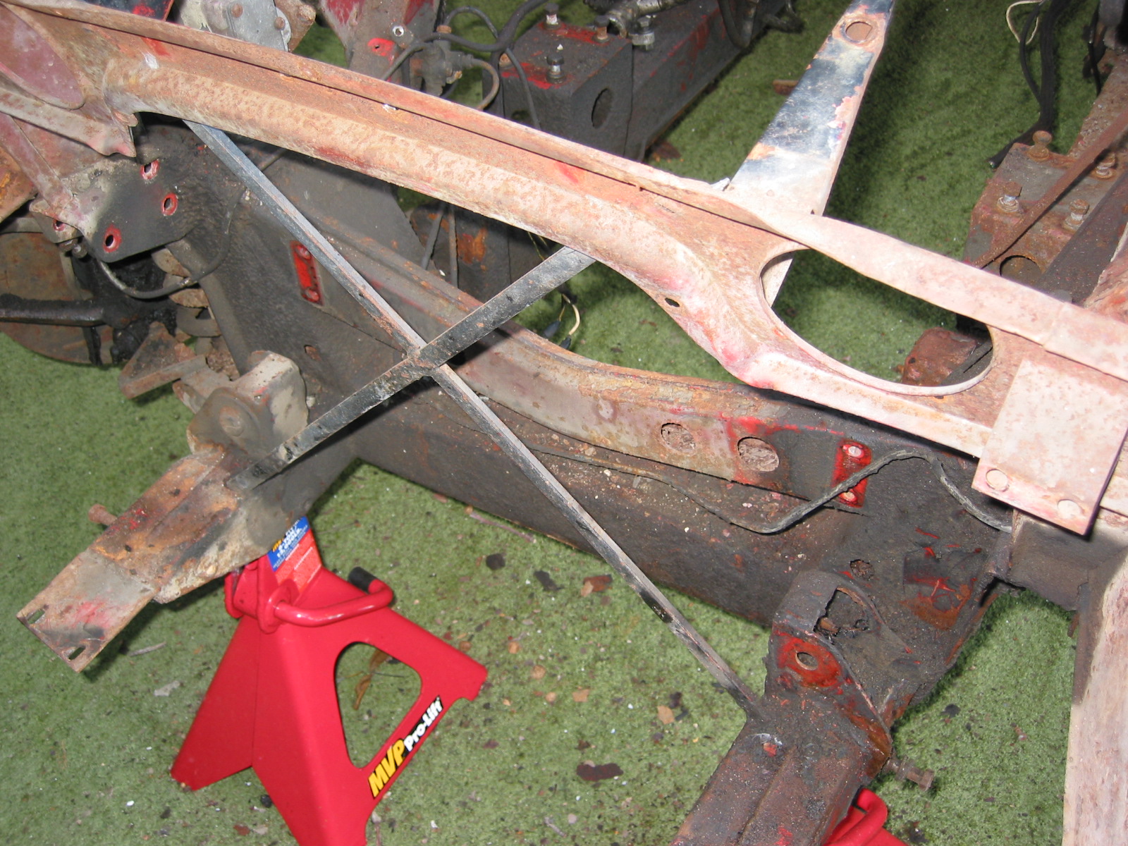
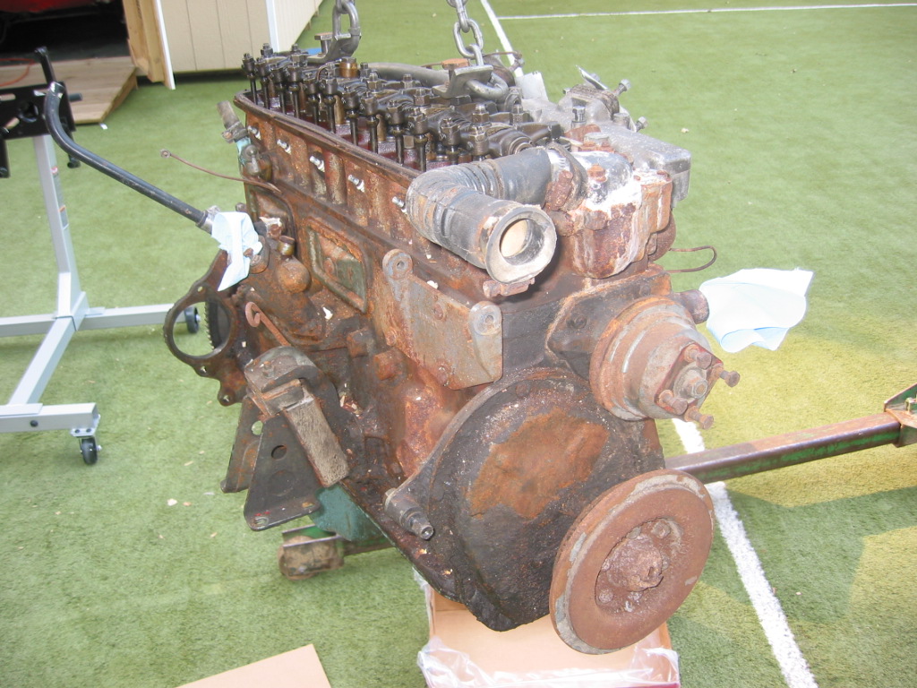
Rough Body 2
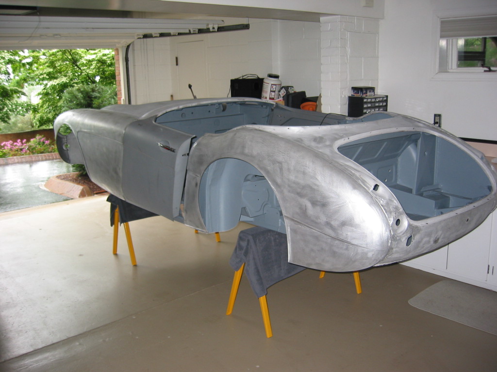
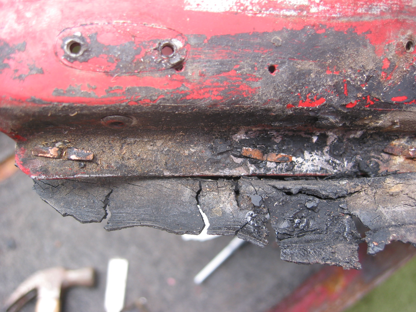
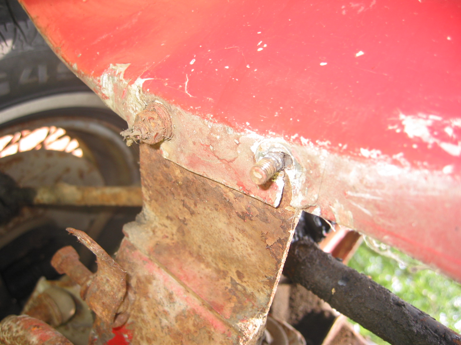
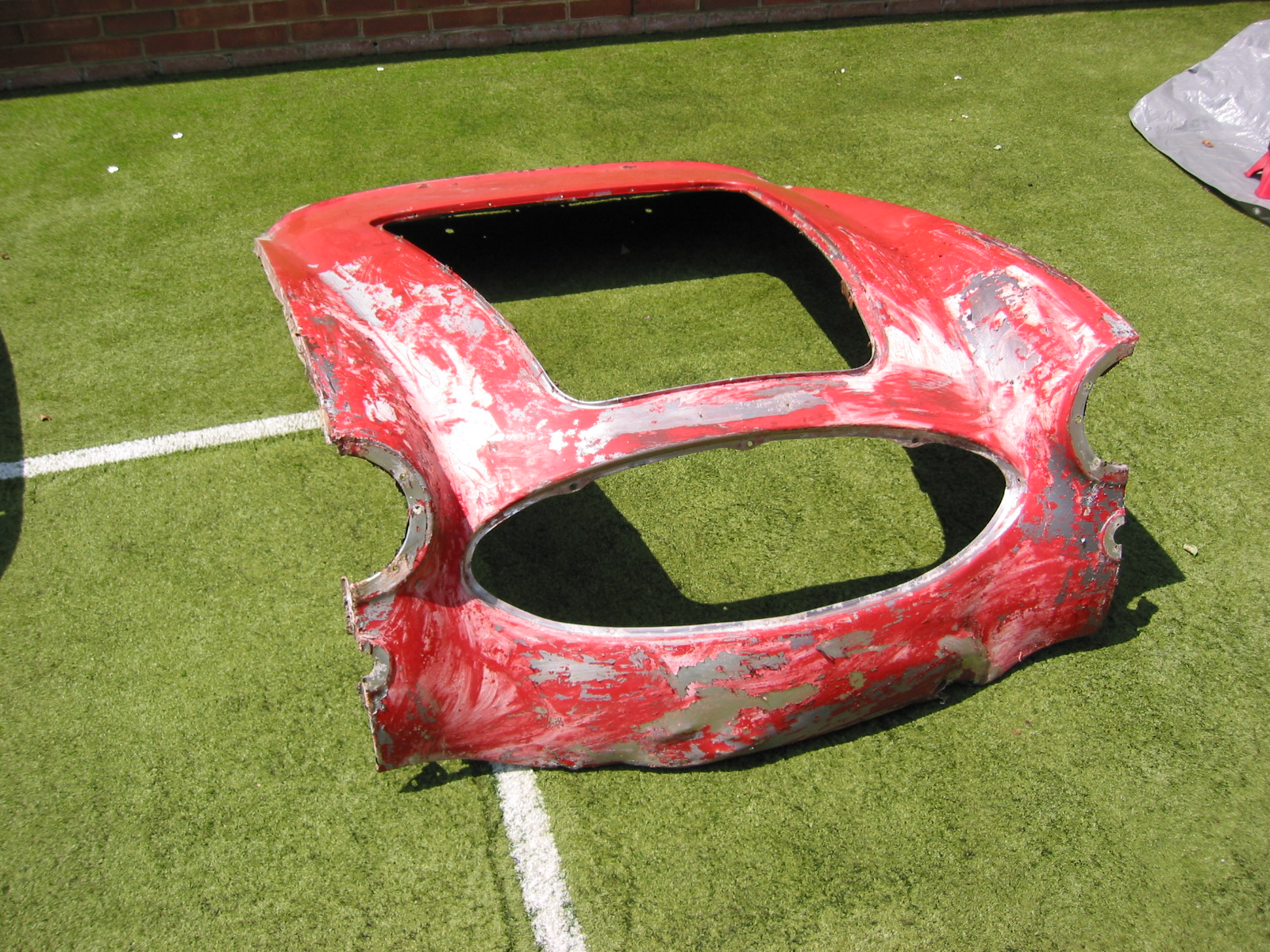
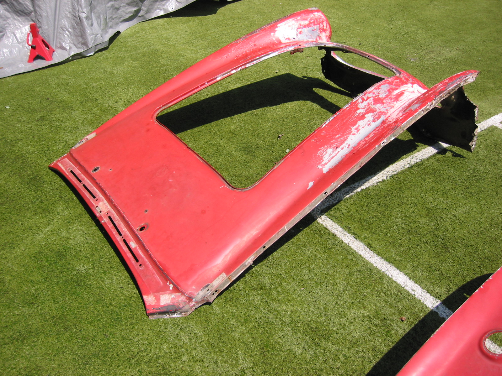
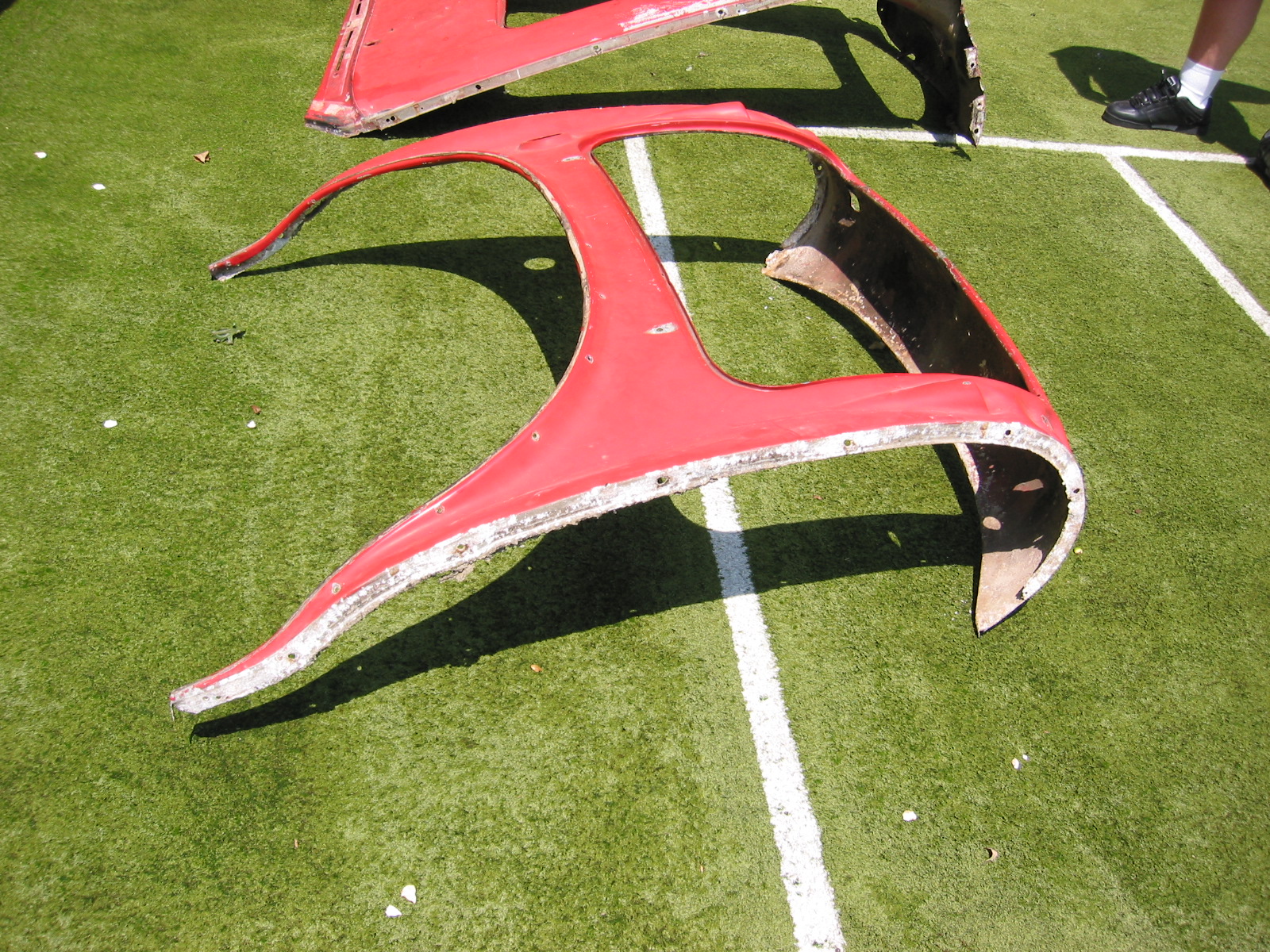
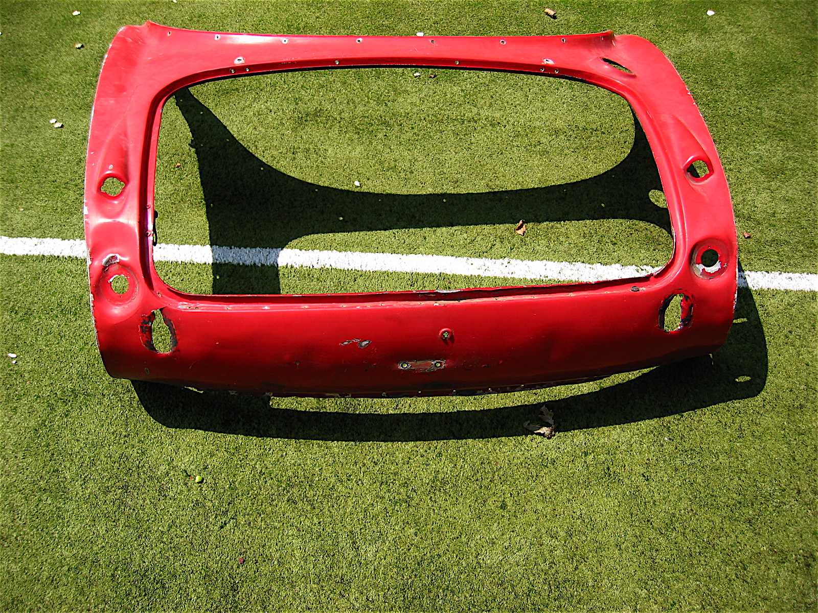
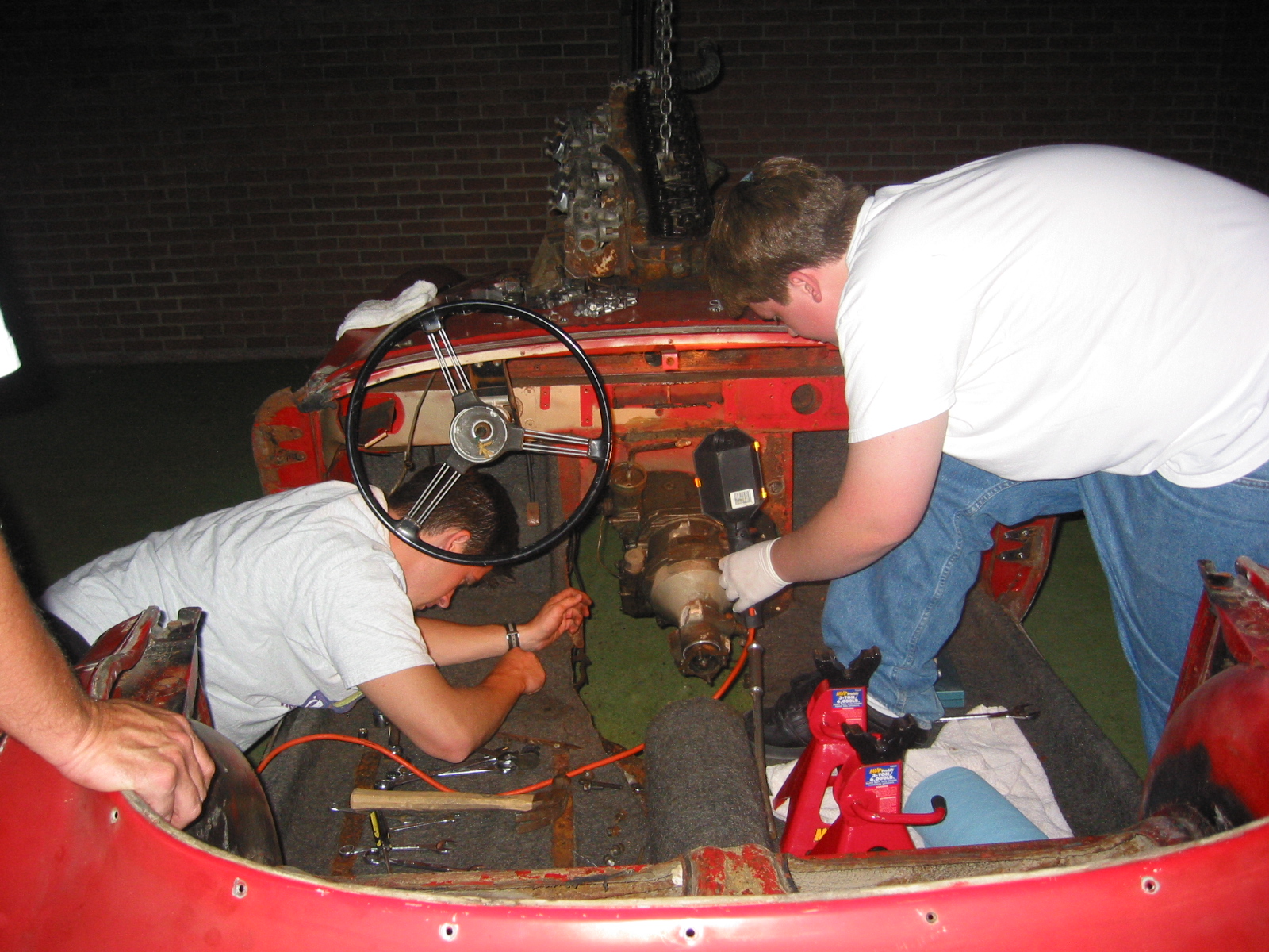
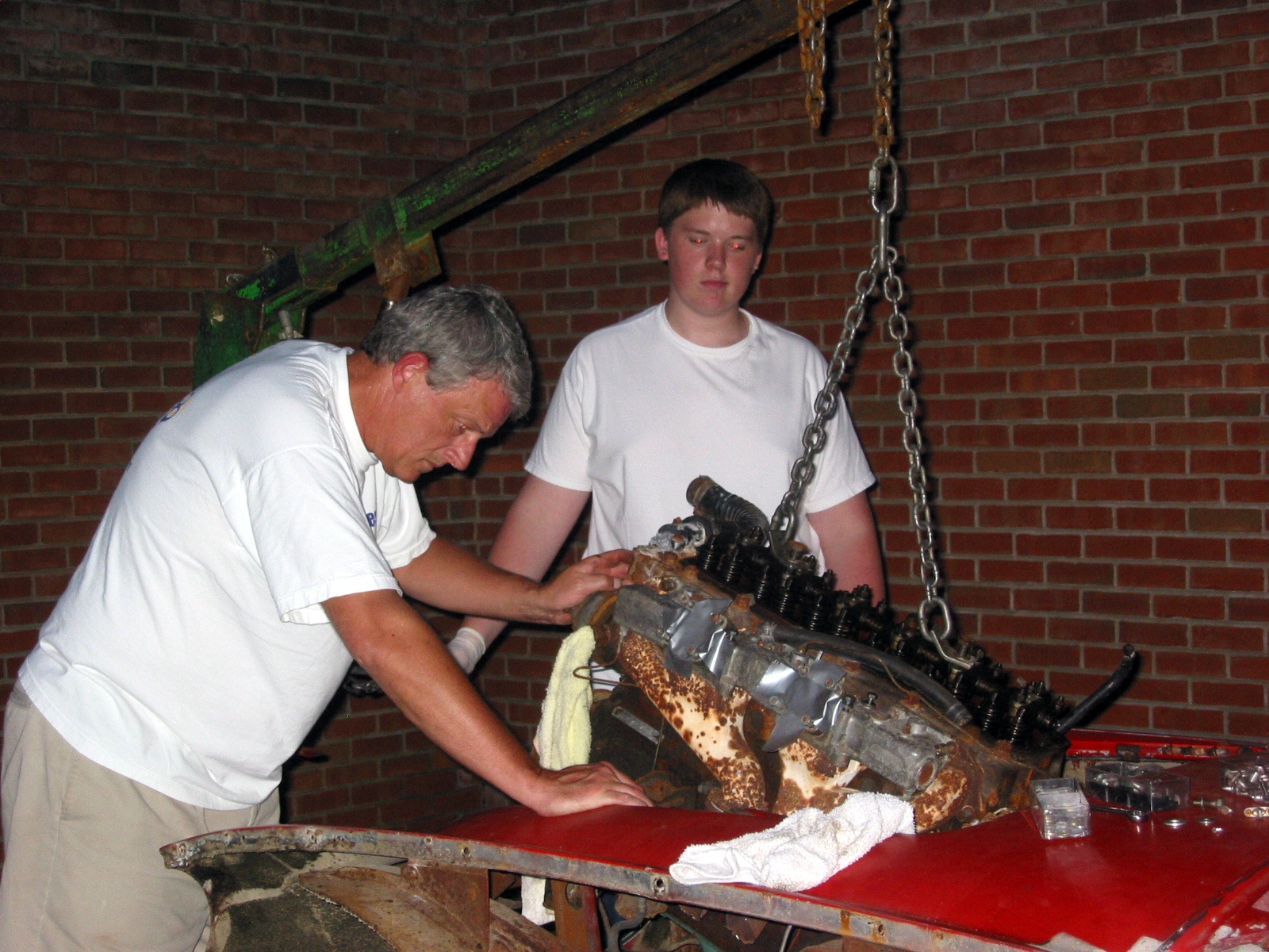
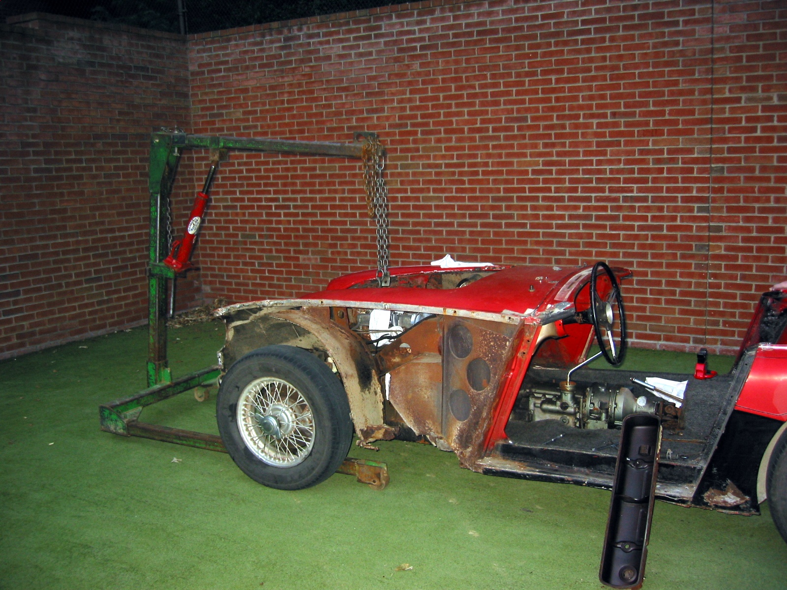
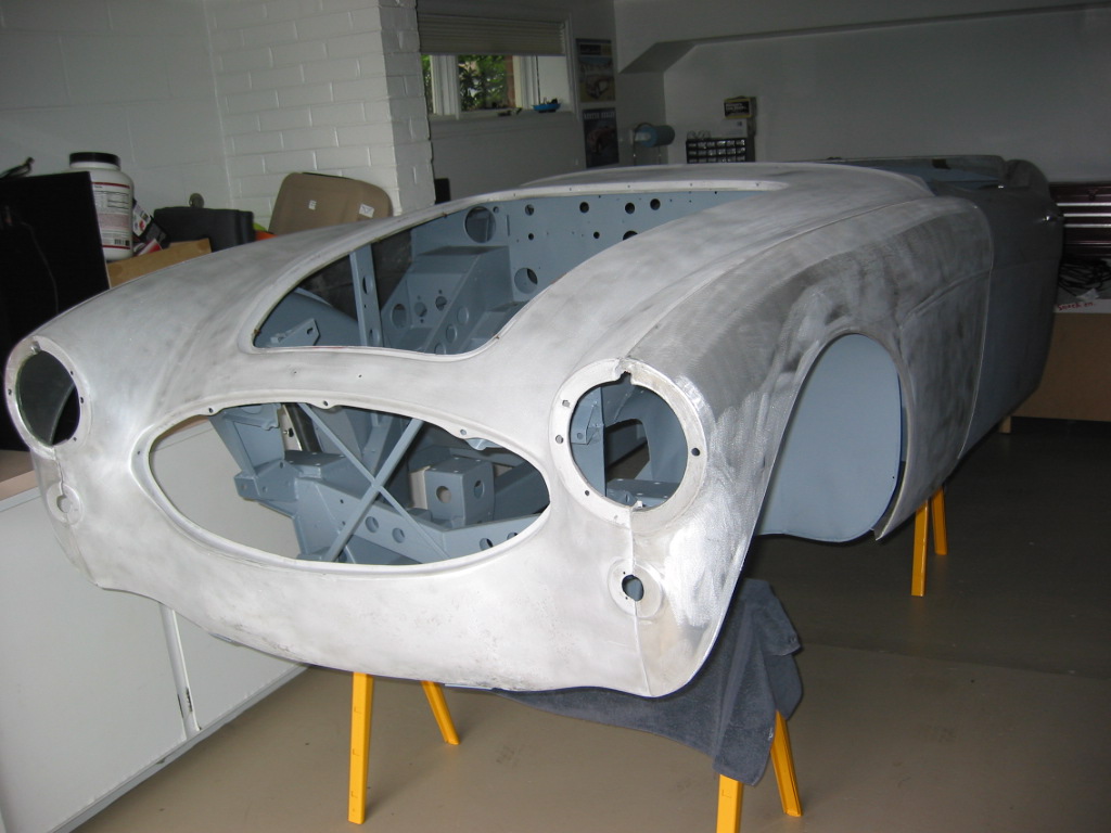
Rough Body
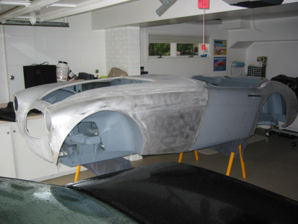
Rough Body 3
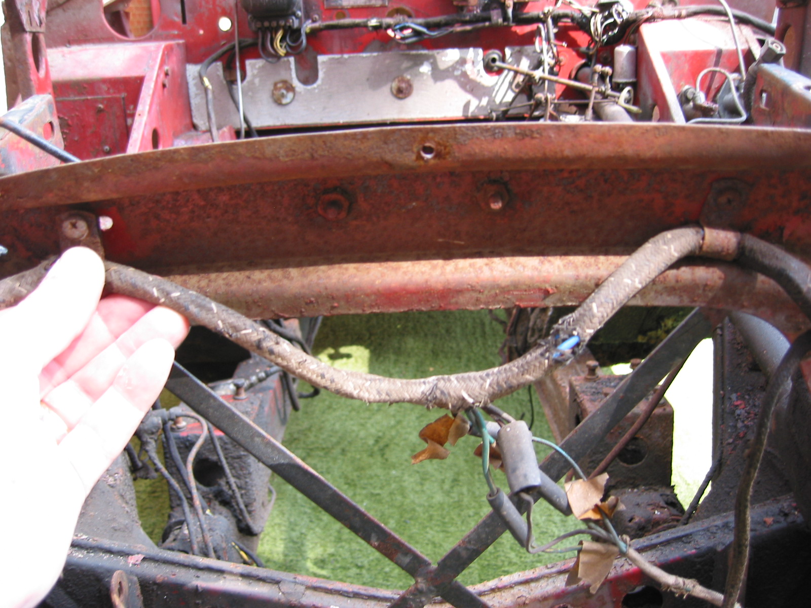
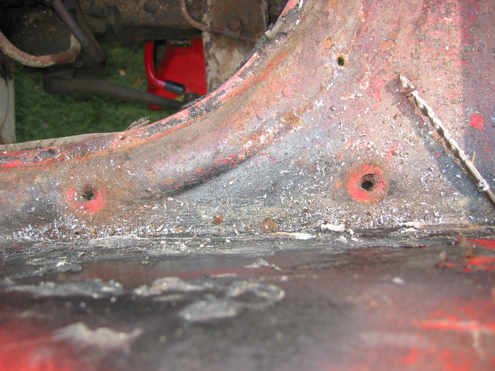
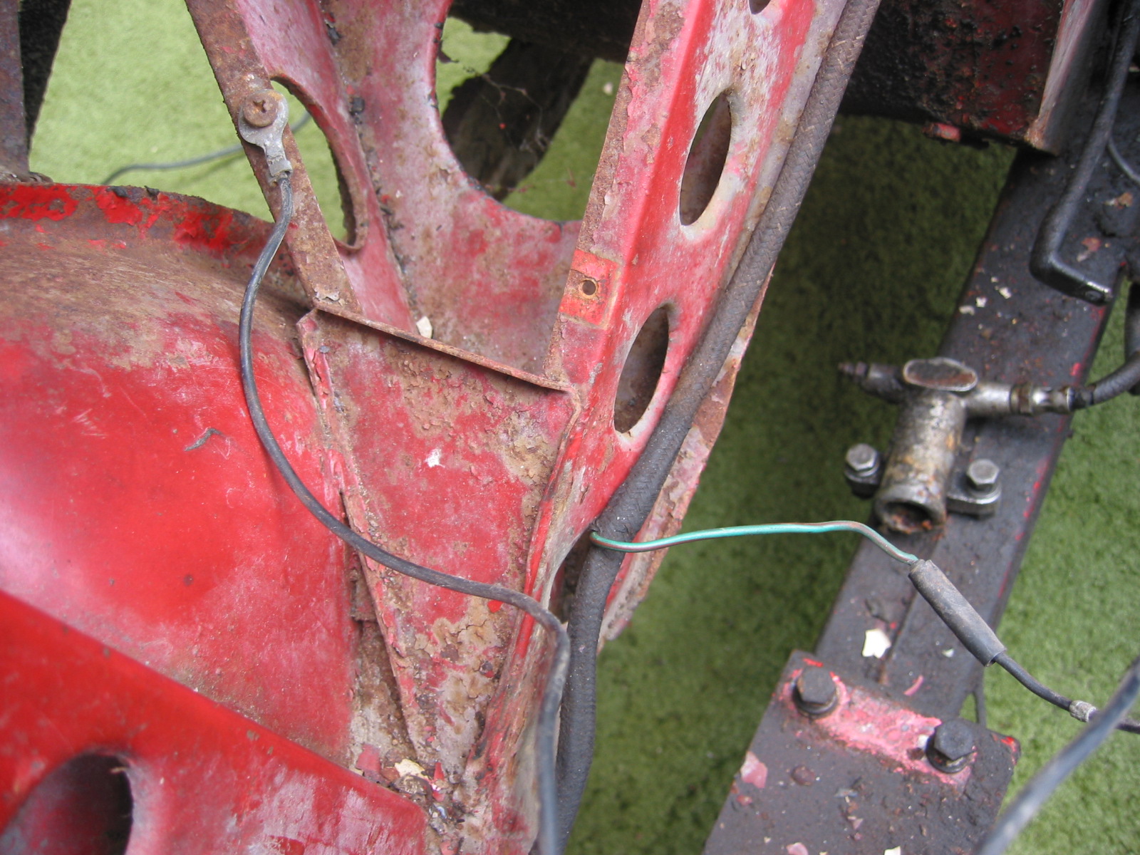
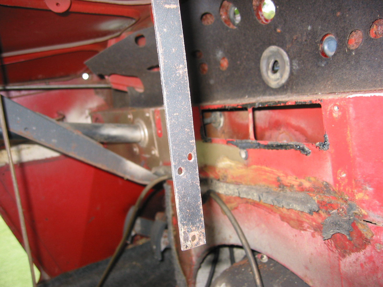
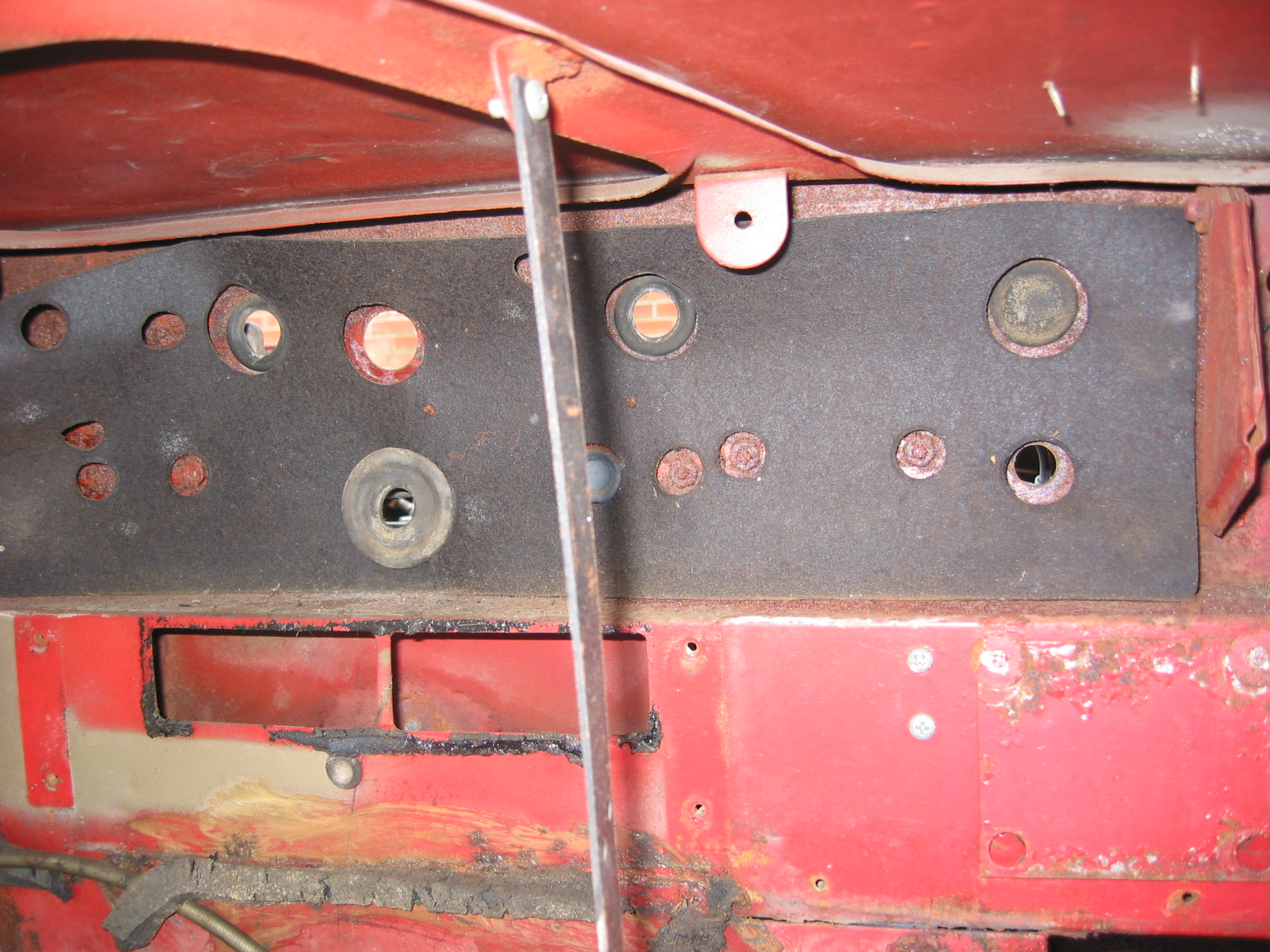
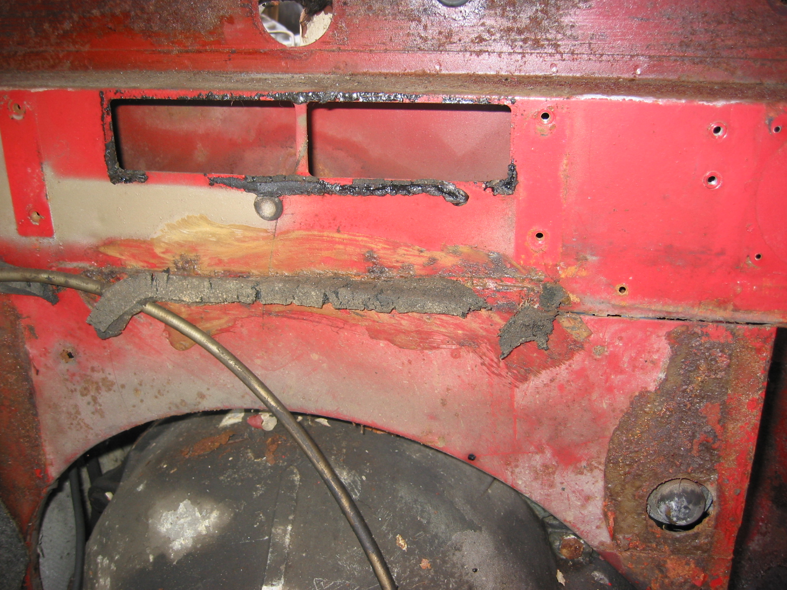
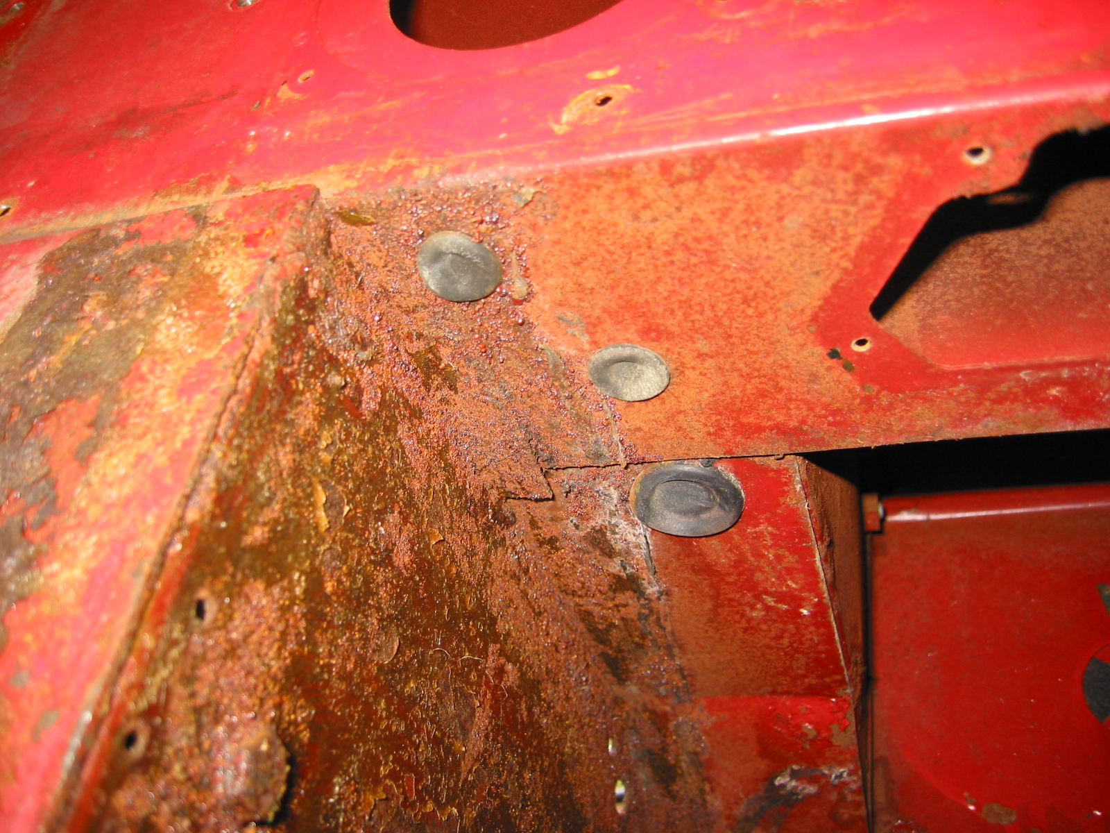
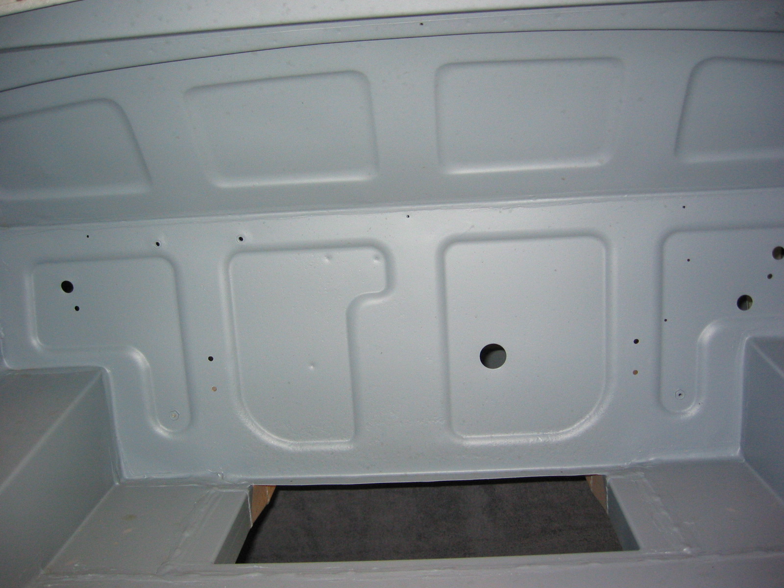
The frame and superstructure looked great. The fit of the wings will have to be improved upon. Door fit is pretty good, but will also need additional work. New edges were put on the rear shroud and rough repairs to the front shroud lower panel were made as well as around the rear shroud taillight area. Seeing the interior panels without rust is hard to believe, but they sure look good now! One disappointment is that mounting holes for a number of things are not located on new panels installed by Martin. Seat rails, exhaust mountings, insulation panels and etc will need to be aligned and drilled.
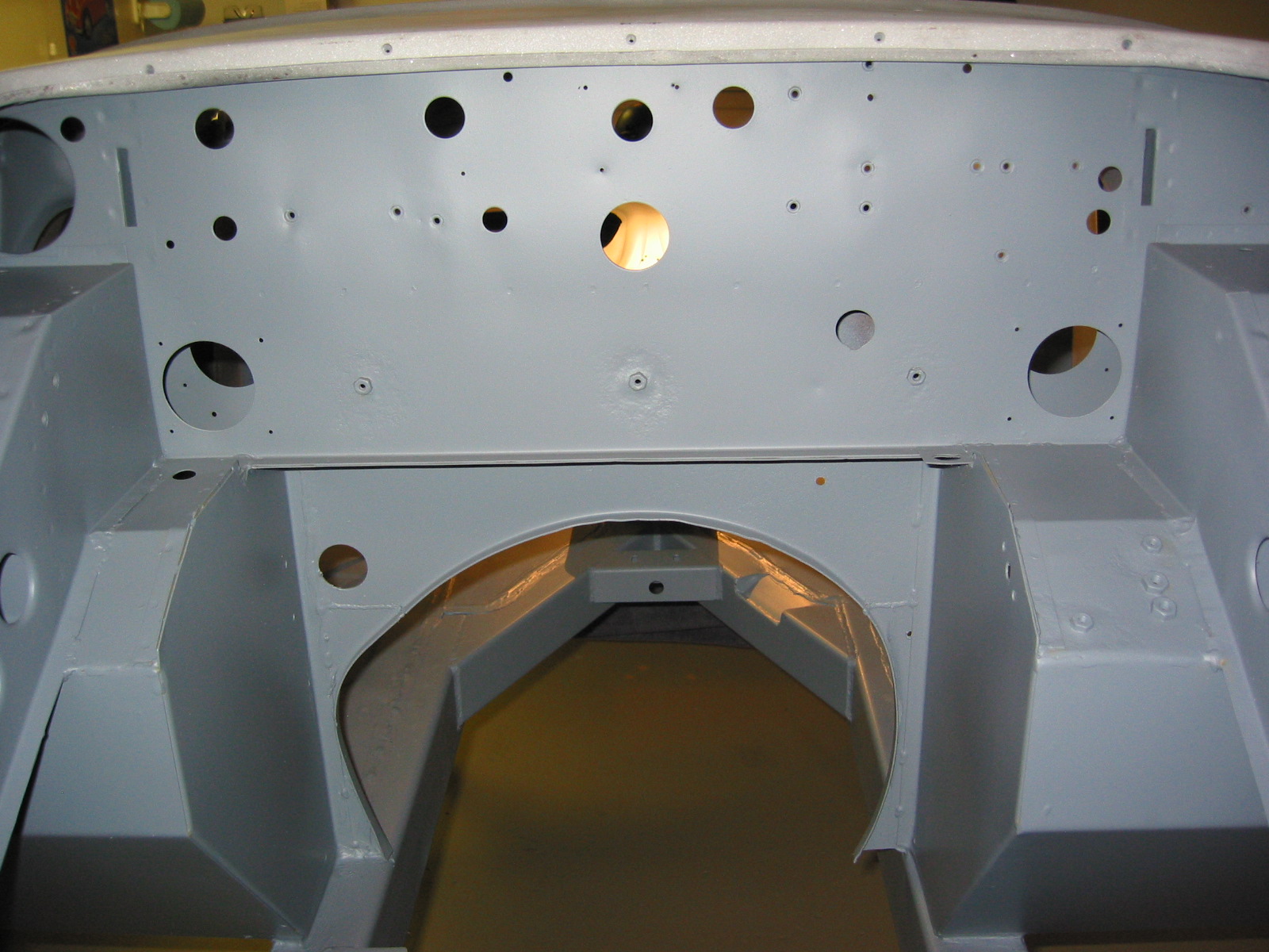
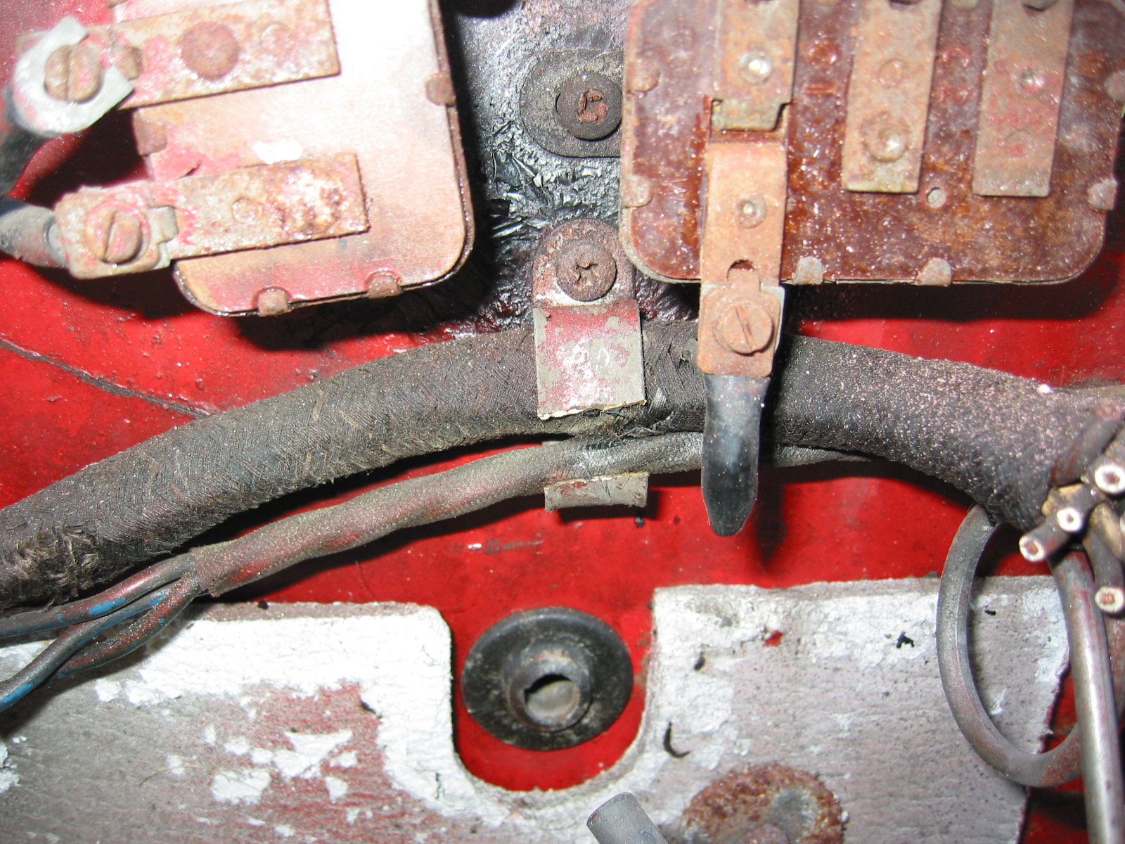
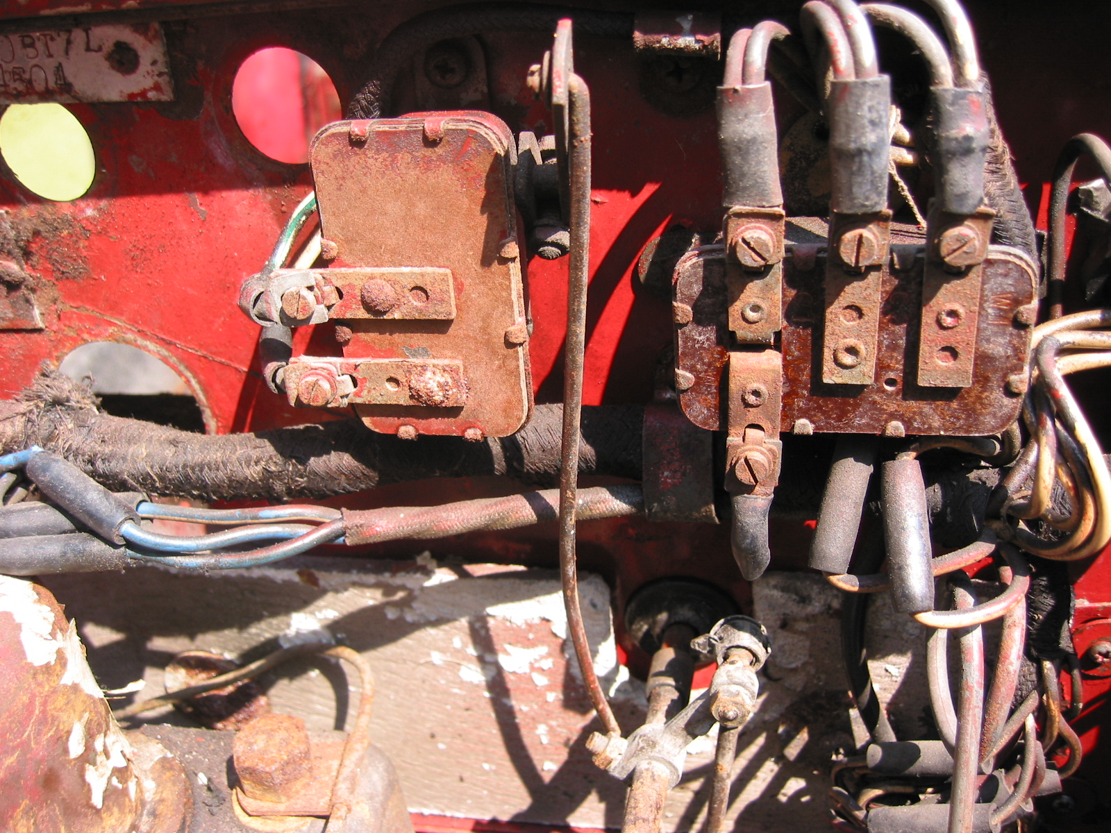
Firewall 3
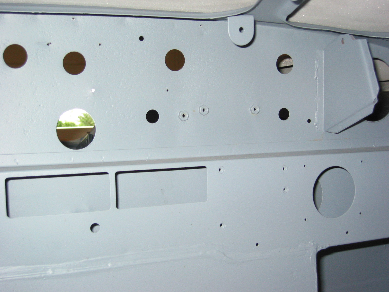
Firewall 2
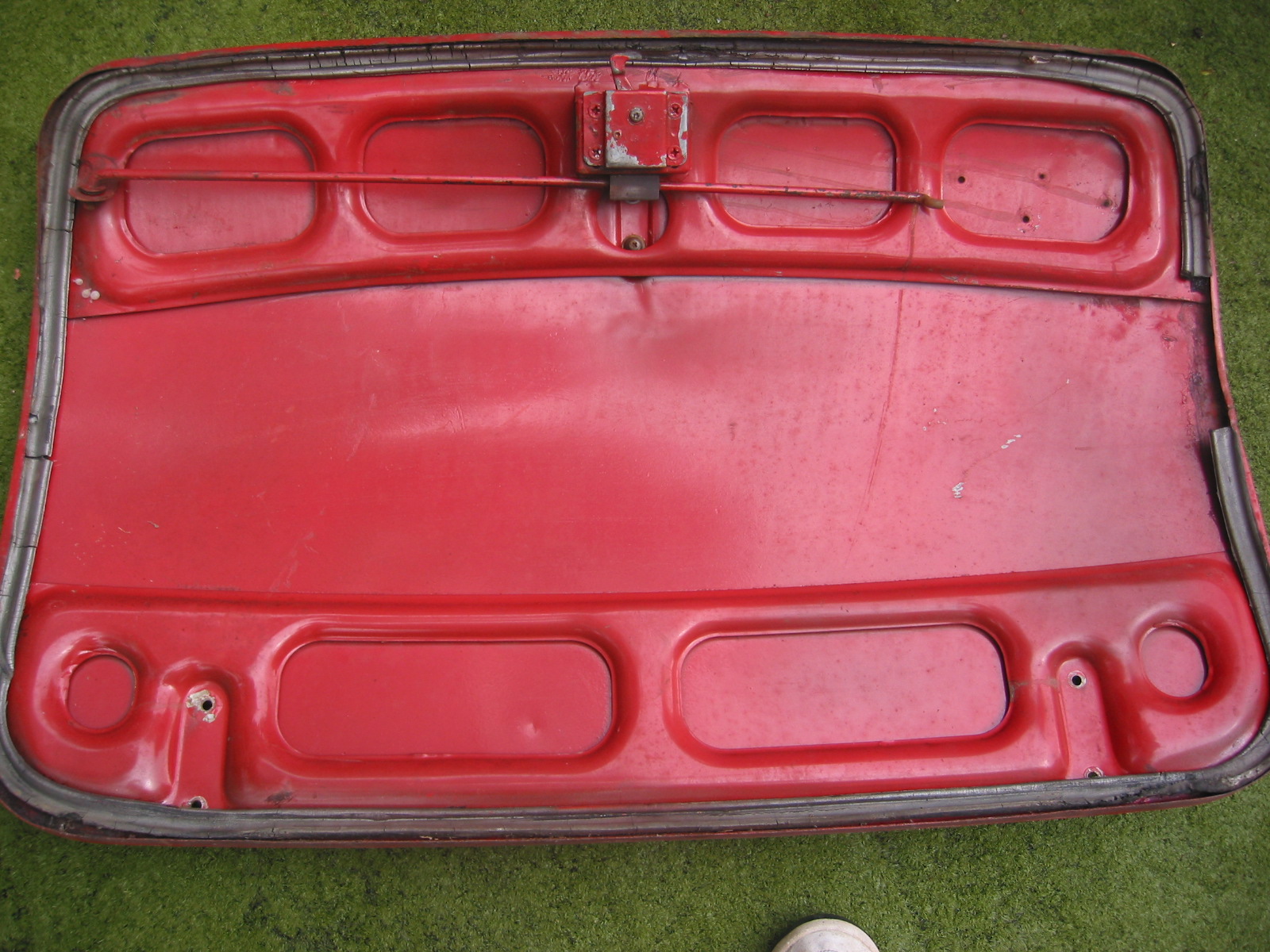
Boot 1
July 15, 2003
Maple Hill Restorations
After consulting with Jeremy Turner from Maple Hill Restorations we have decided to completely assemble the car while in primer to be ensured that EVERYTHING fits properly. This will prolong the project, and will probably lead to some short term frustration, but should also minimize problems with assembly once body work and painting is complete.
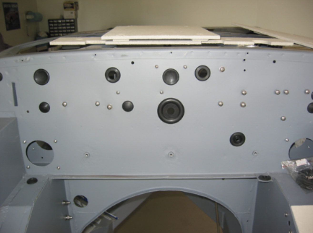
My first step is to determine proper fastener sizes and replace all original hardware with stainless steel, with the exception of higher load locations such as shock absorber and other suspension bolts. Those will be replaced with new grade 8 zinc plated hardware. Then we installed all of the rubber grommets in the firewall, footwell and other locations.
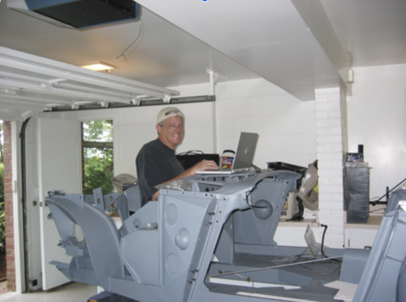
The Scientist at Work
Chased Threads and rubber grommets
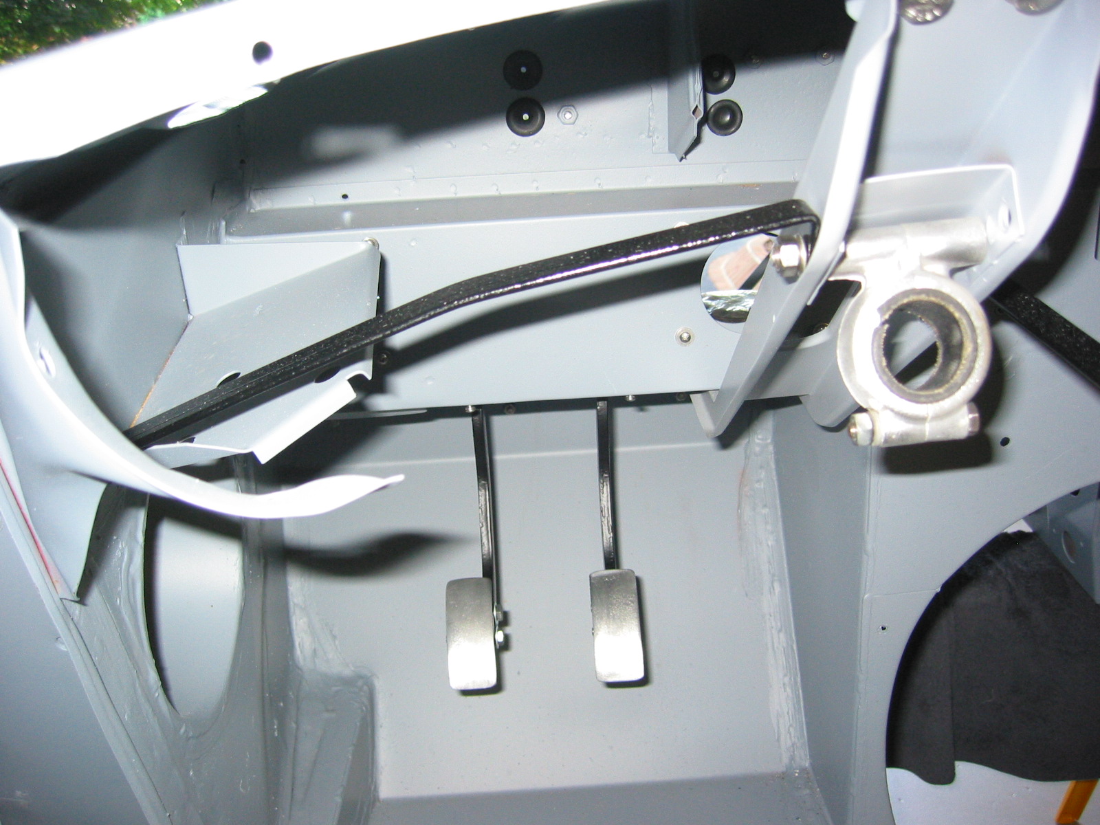
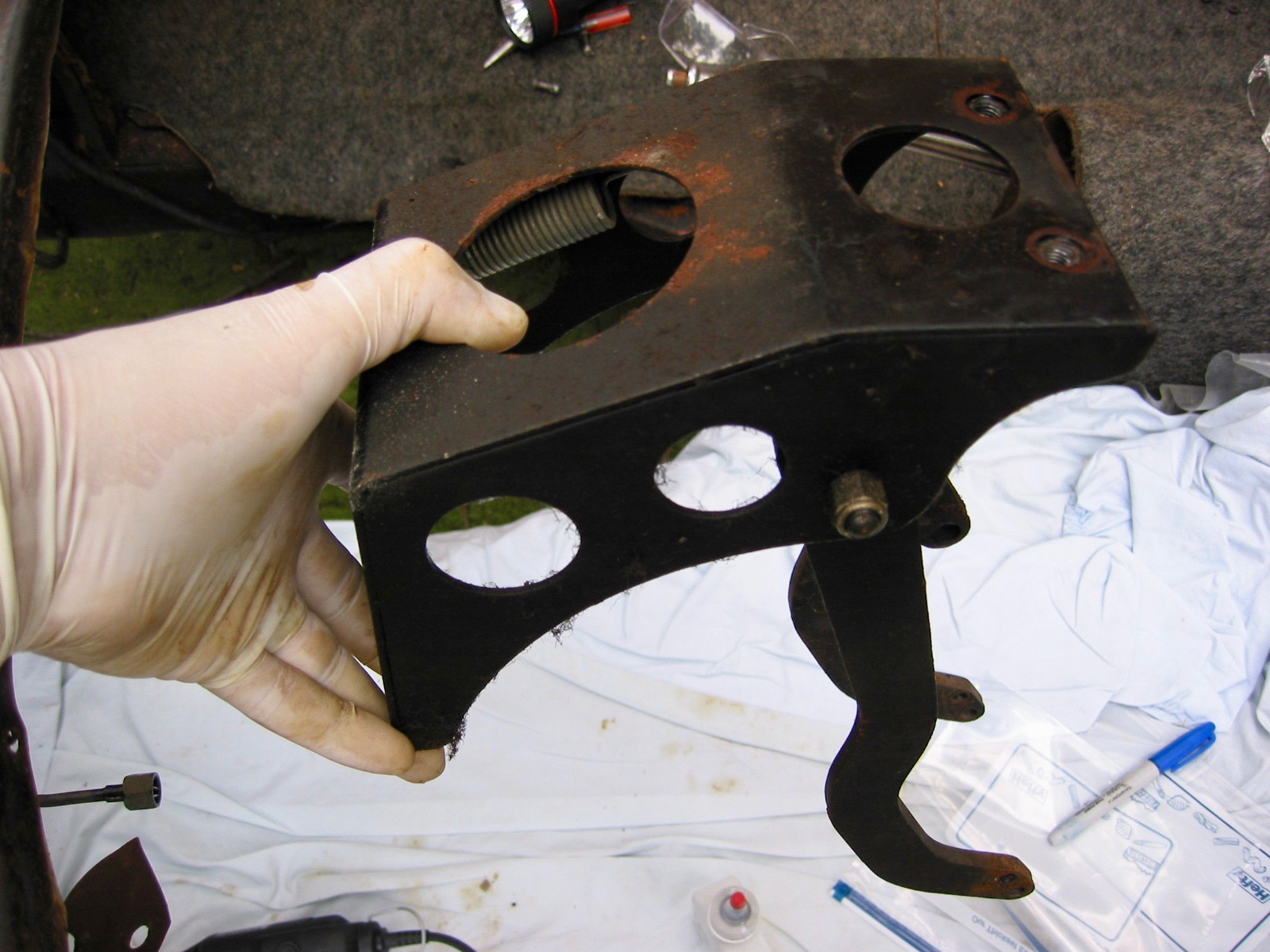
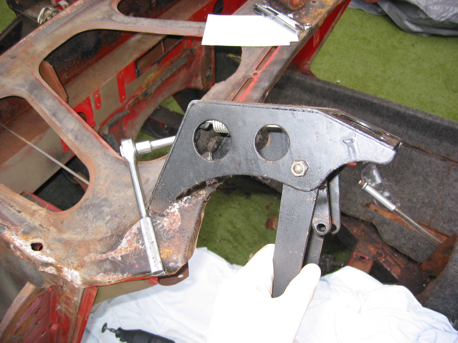
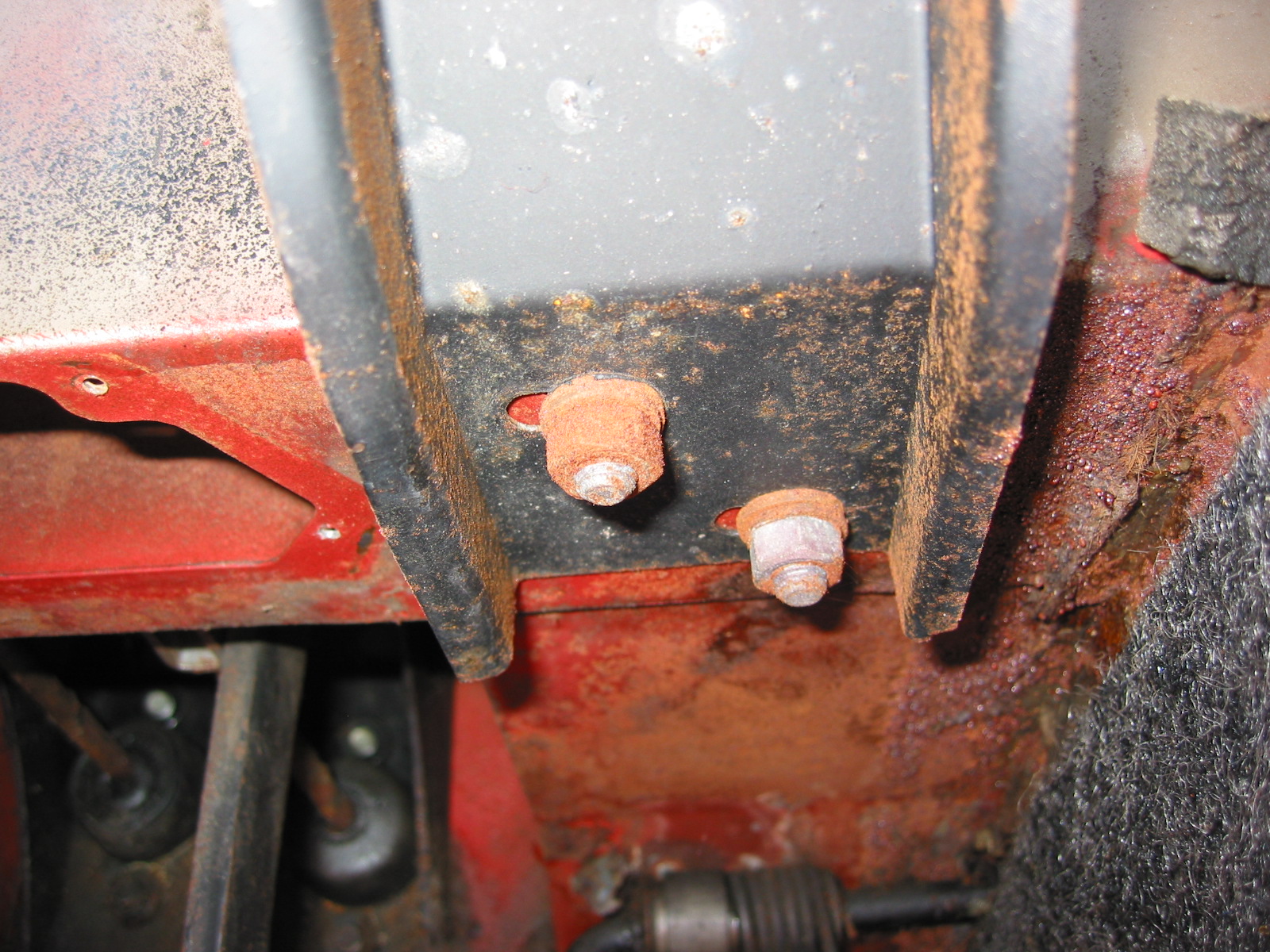
Installed pedal box

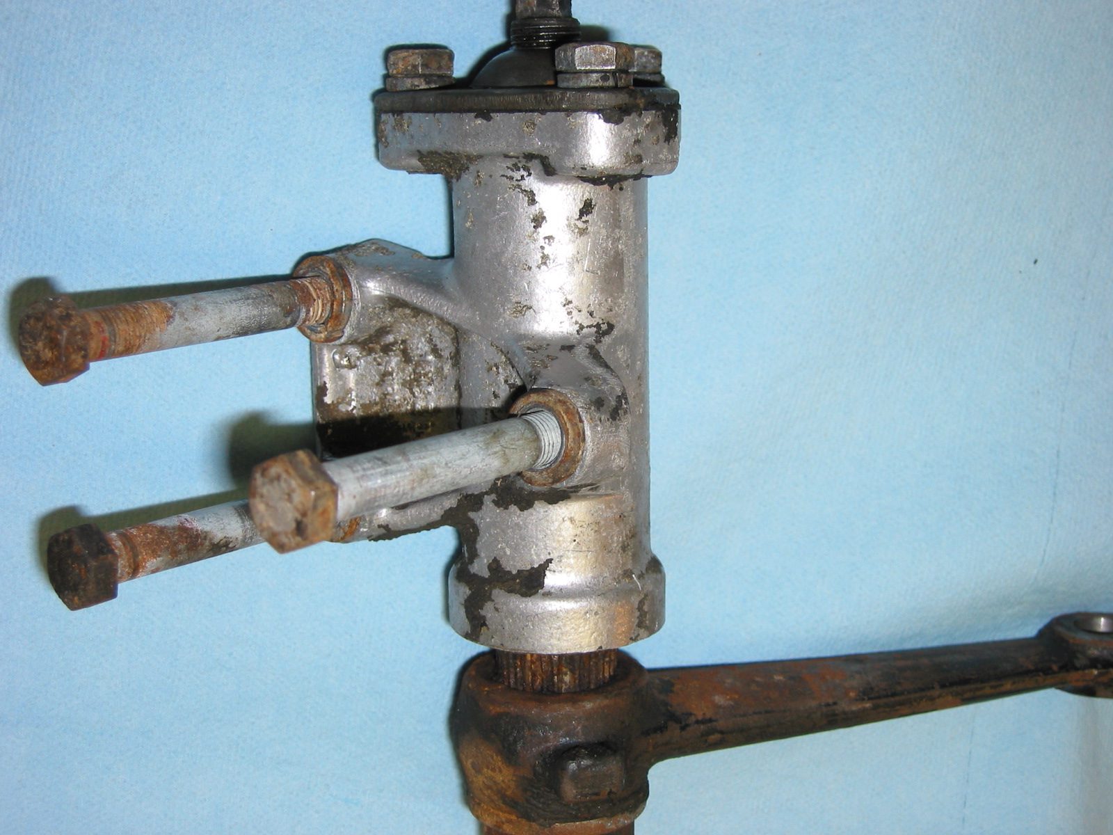
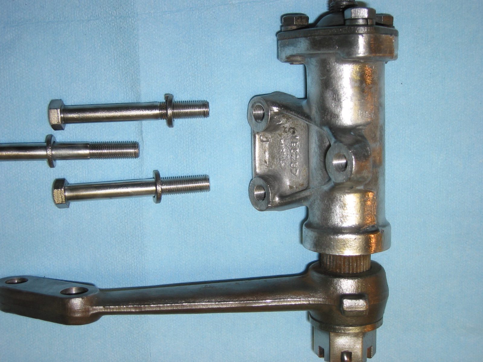
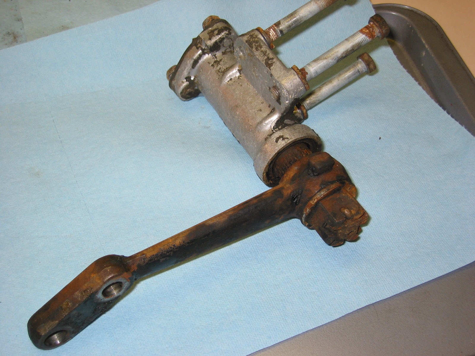
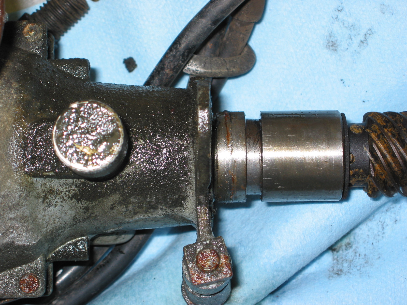
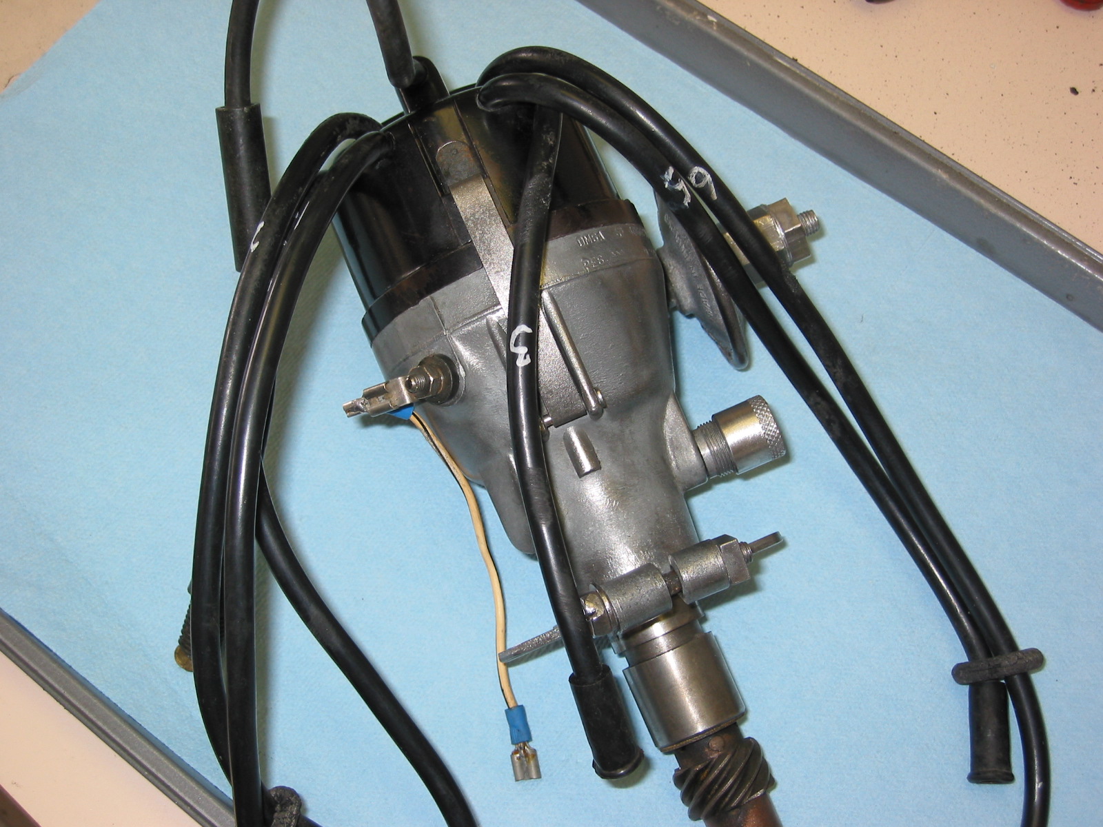
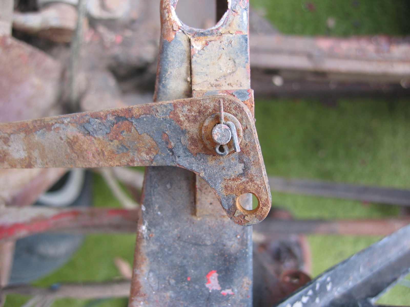
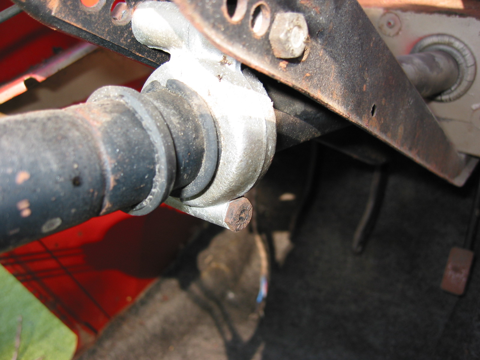
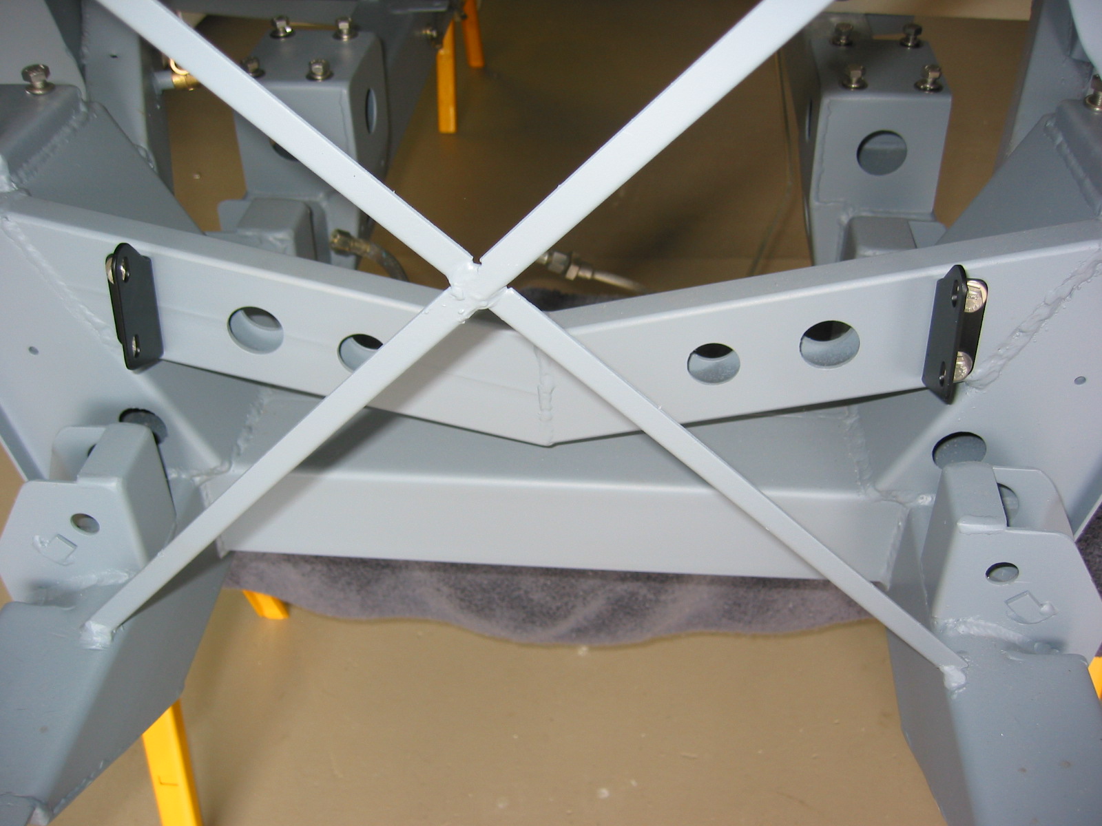
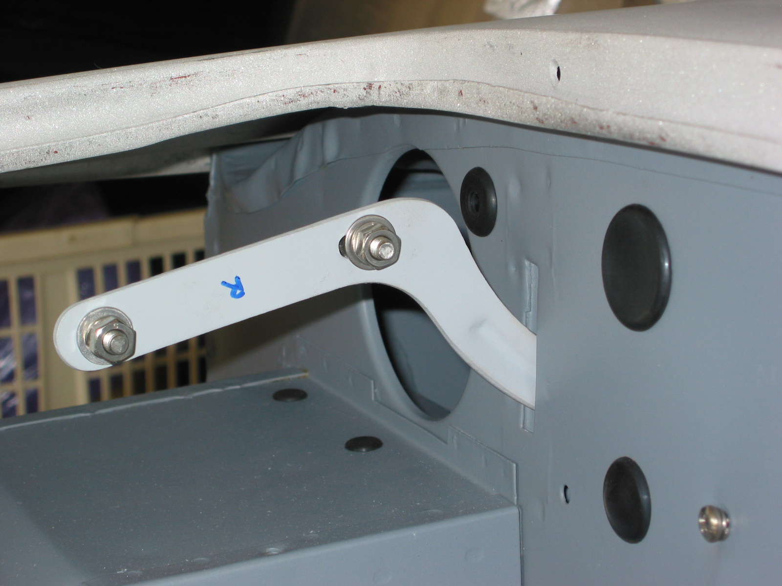
Steering Bracket and Brace
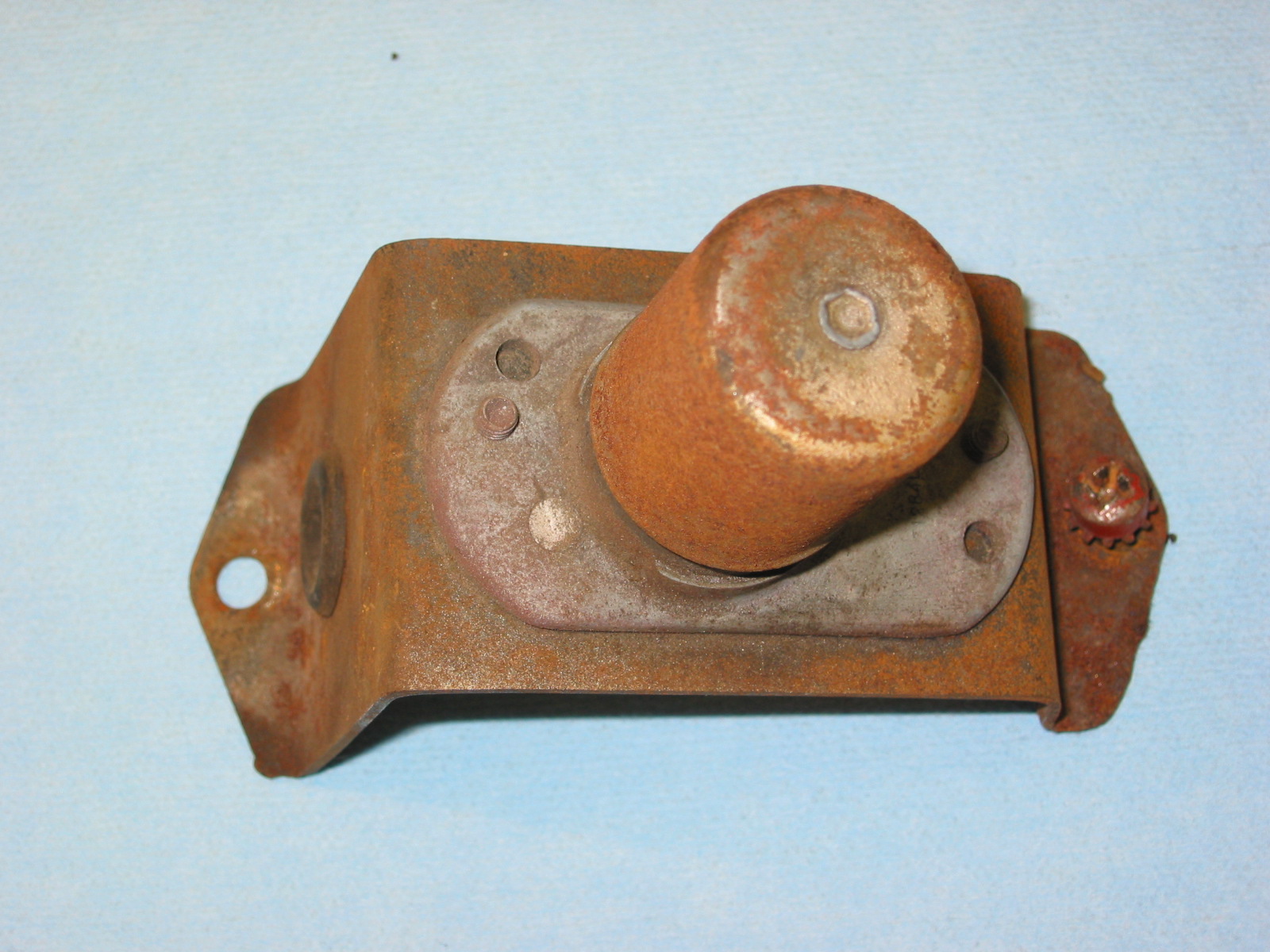
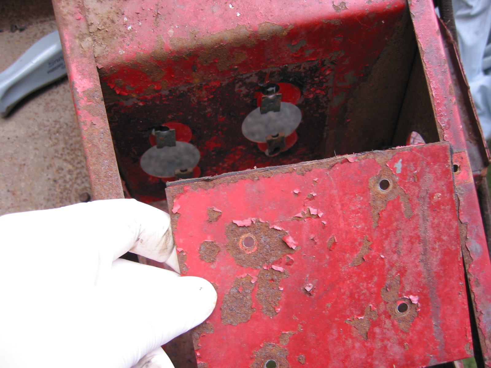
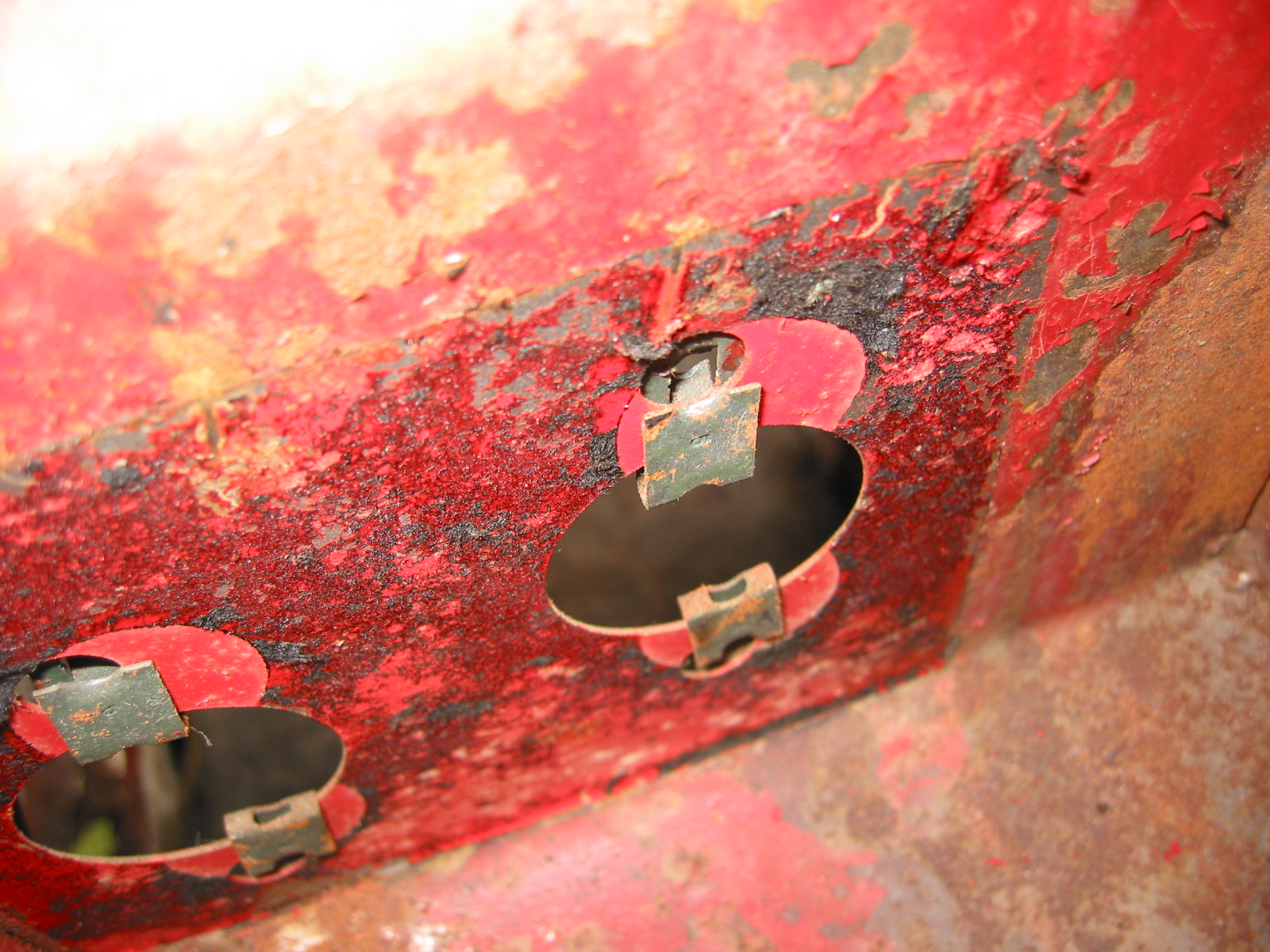
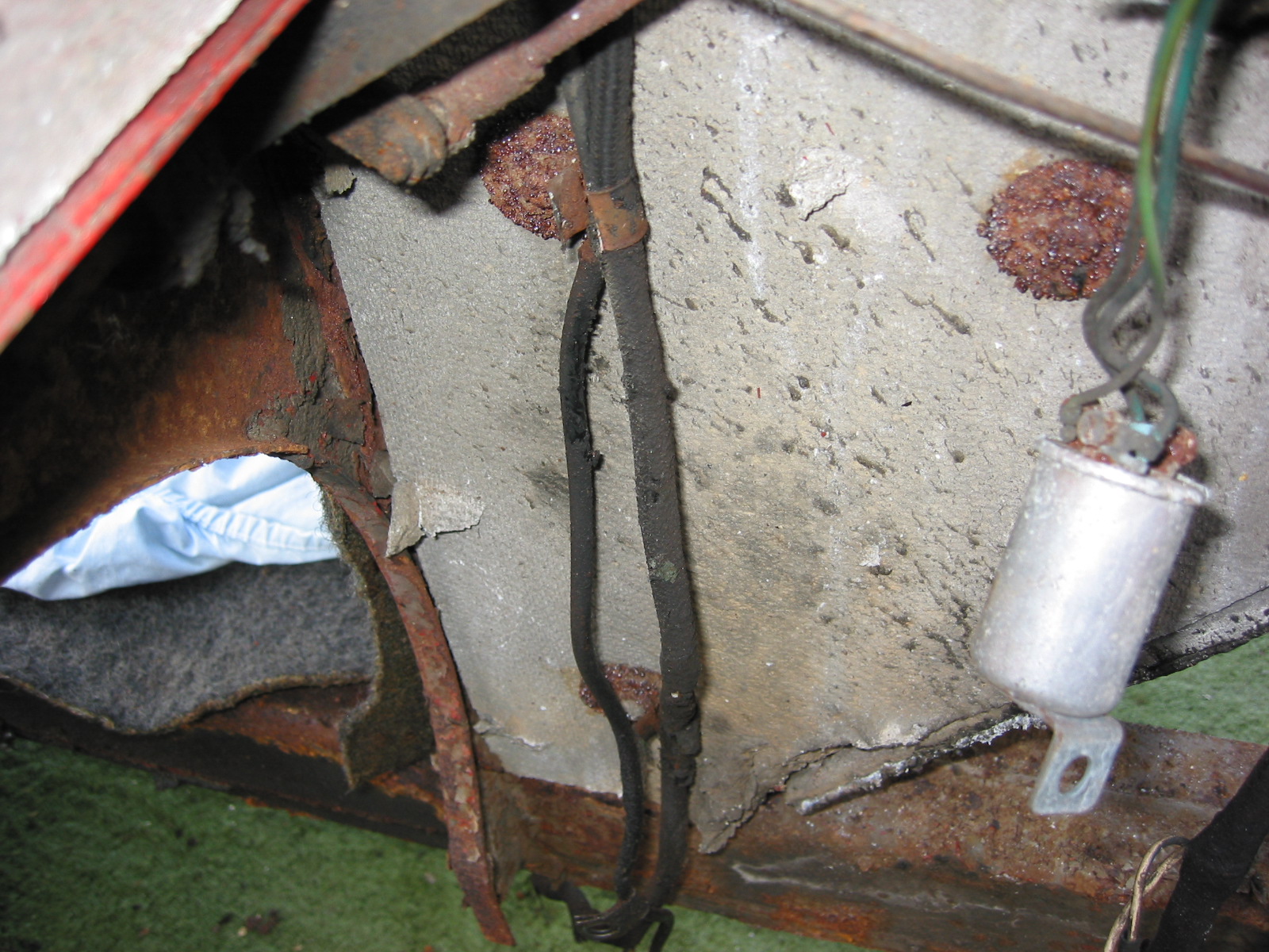
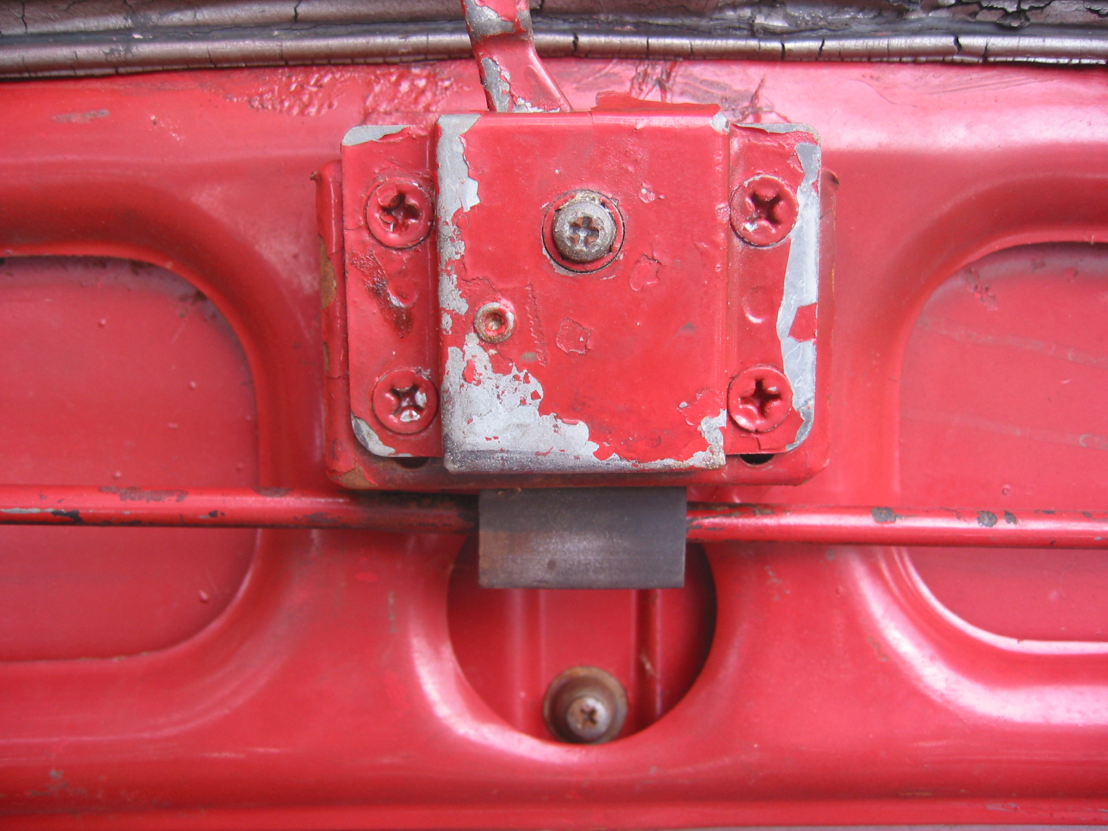
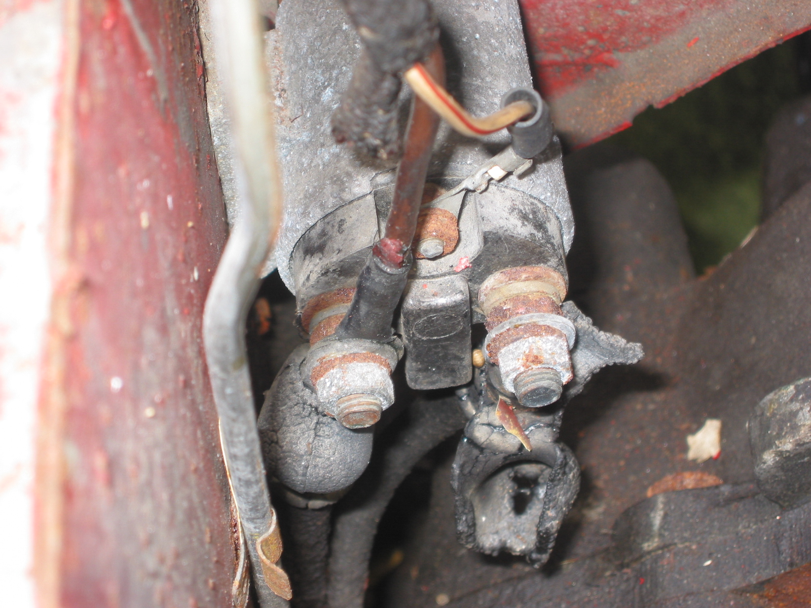
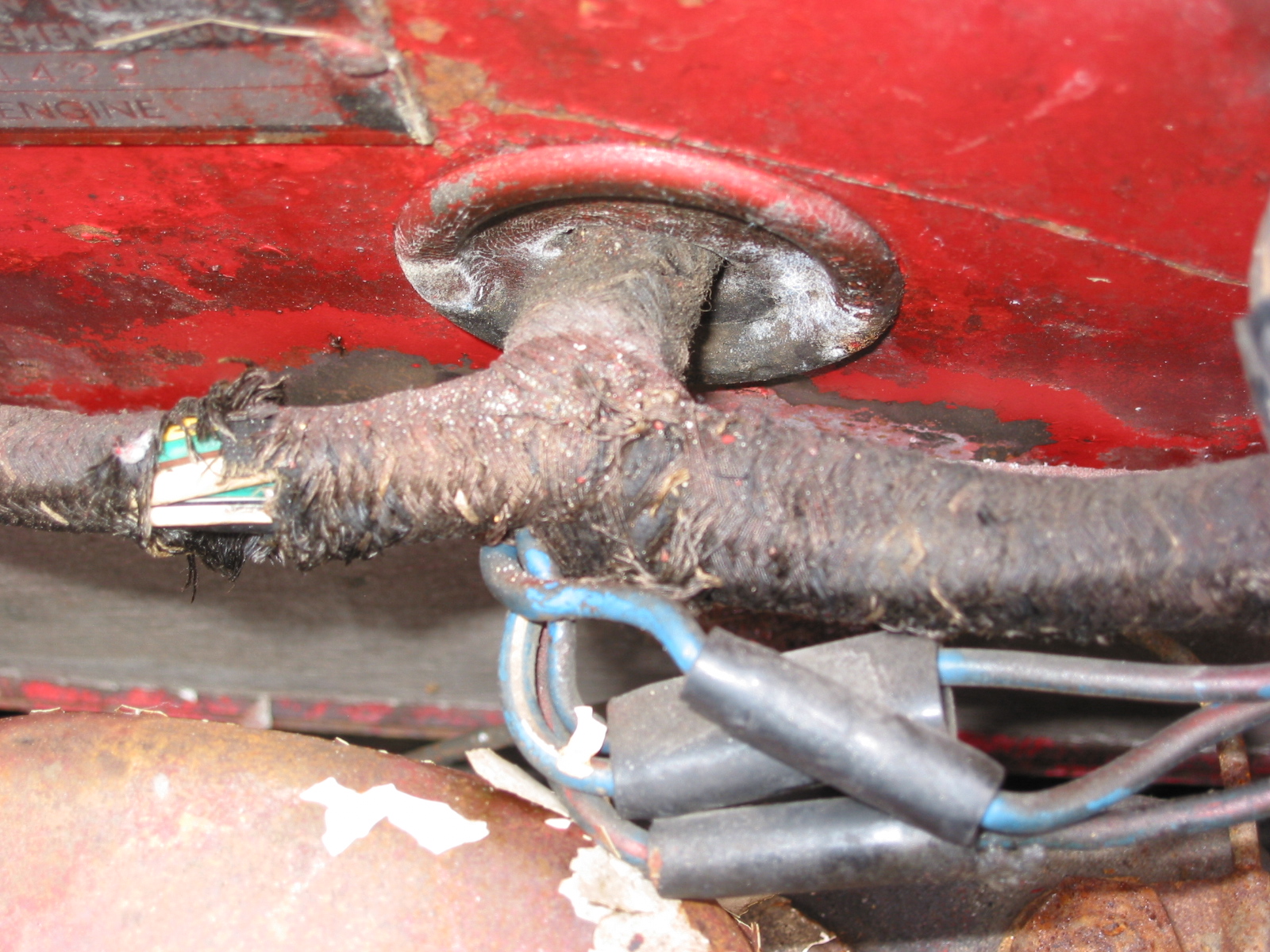
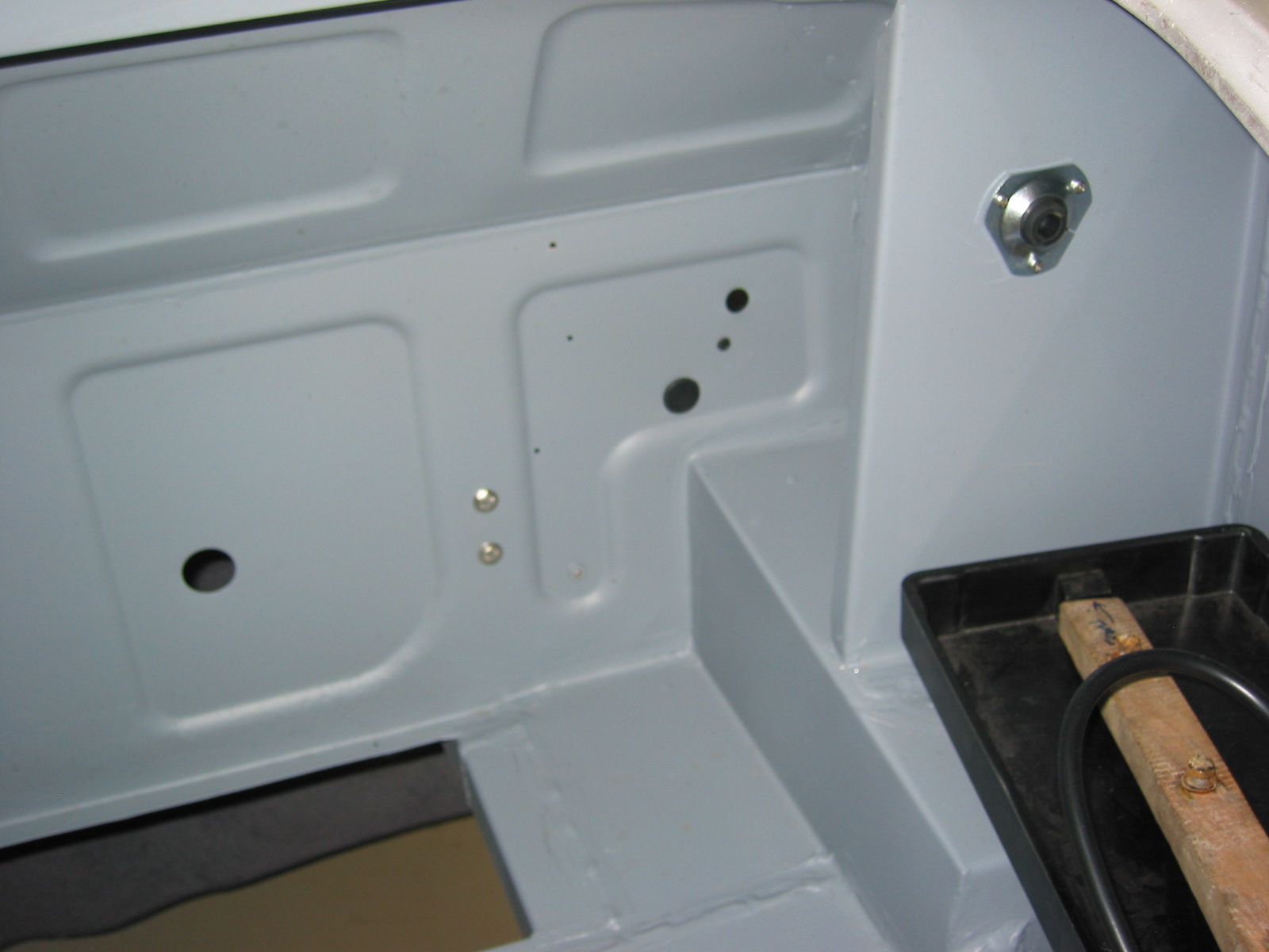
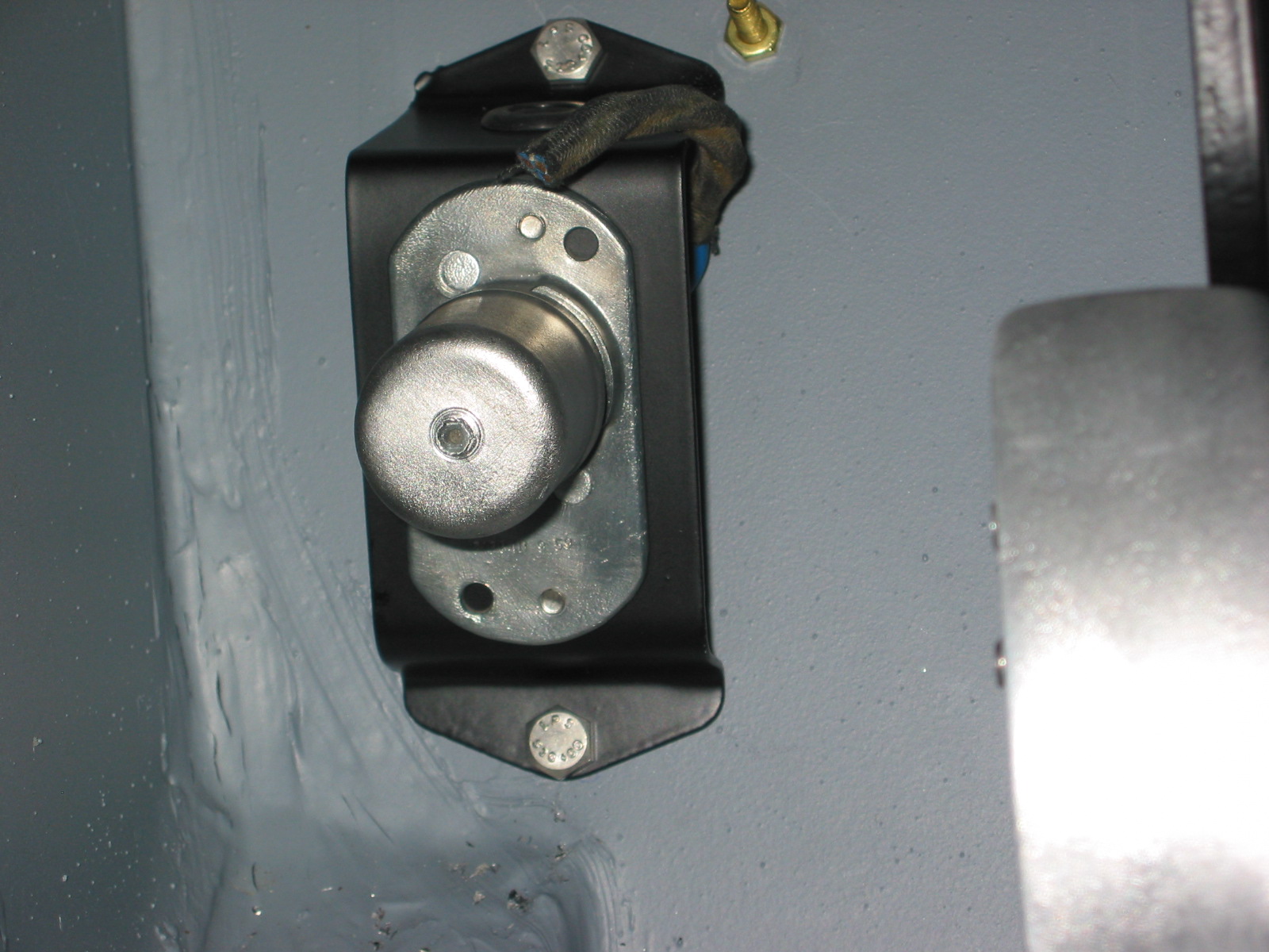
Boot Grommets – The grommet for the battery cable and other bulkhead grommets were installed in the boot. The anti-theft battery switch and bracket were also installed.
Boot grommets
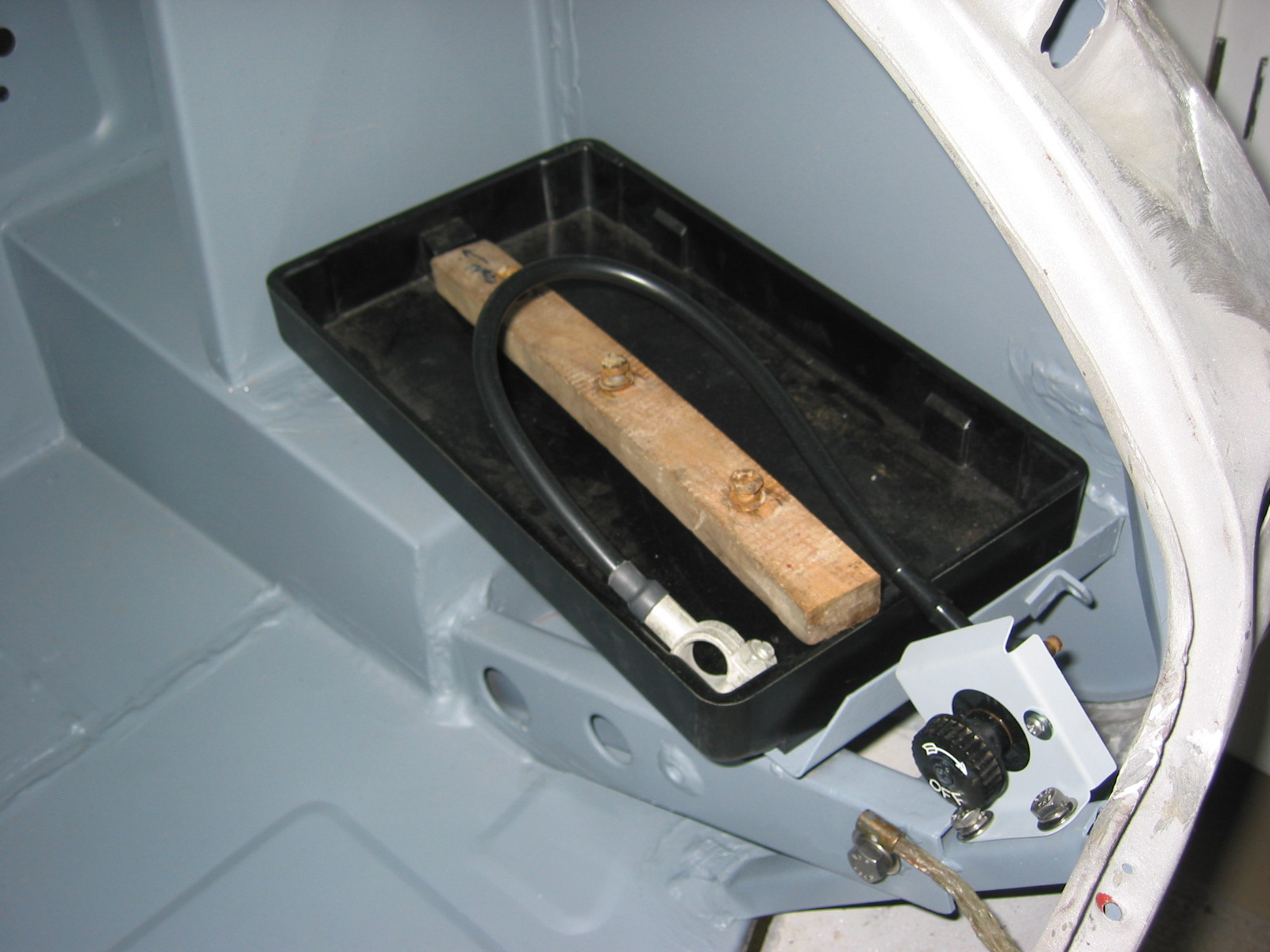
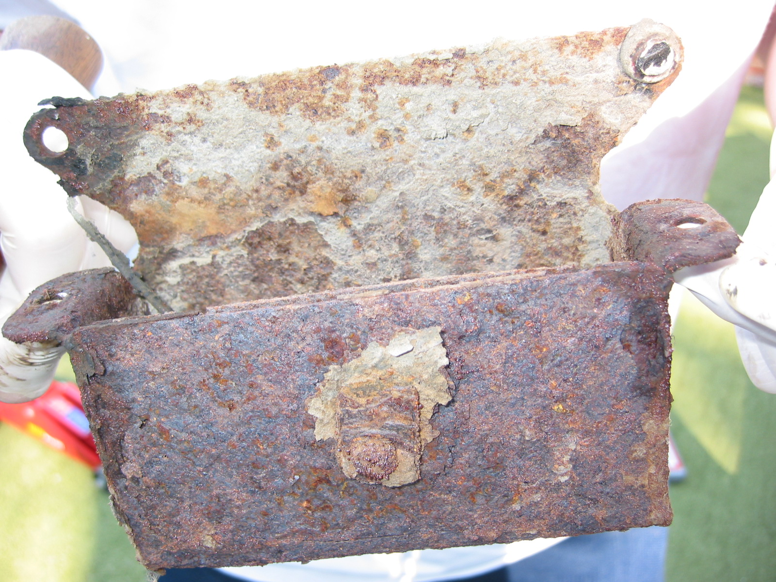
Battery box and switch

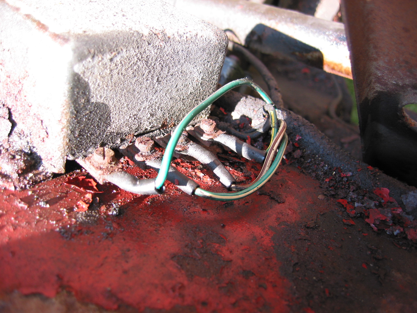
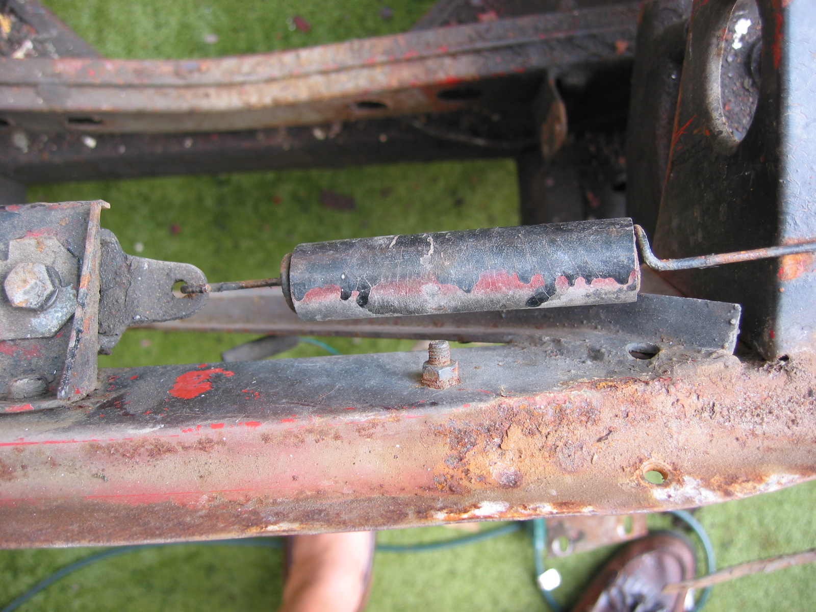
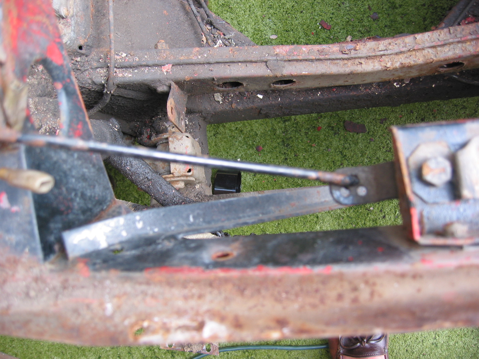
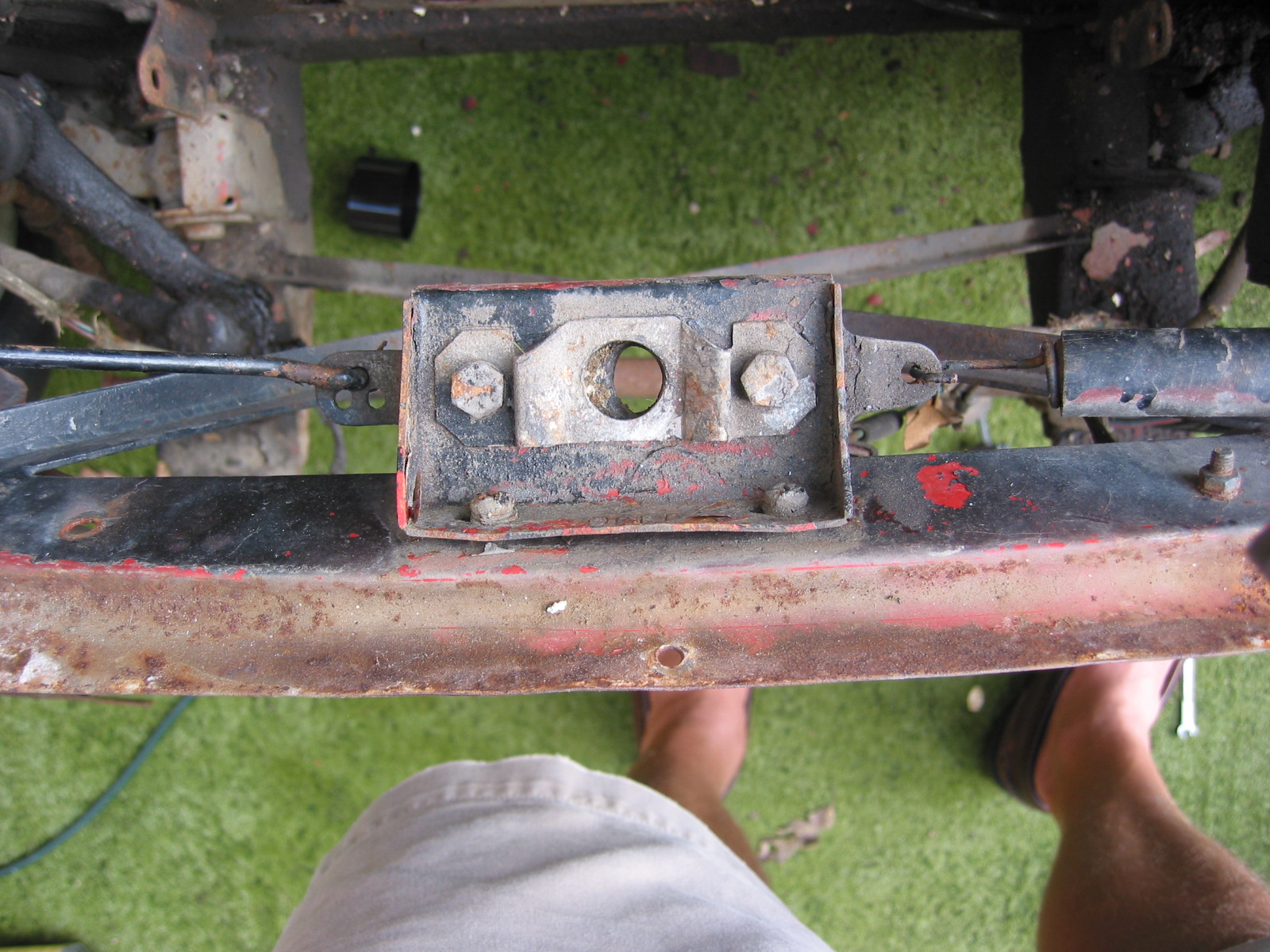
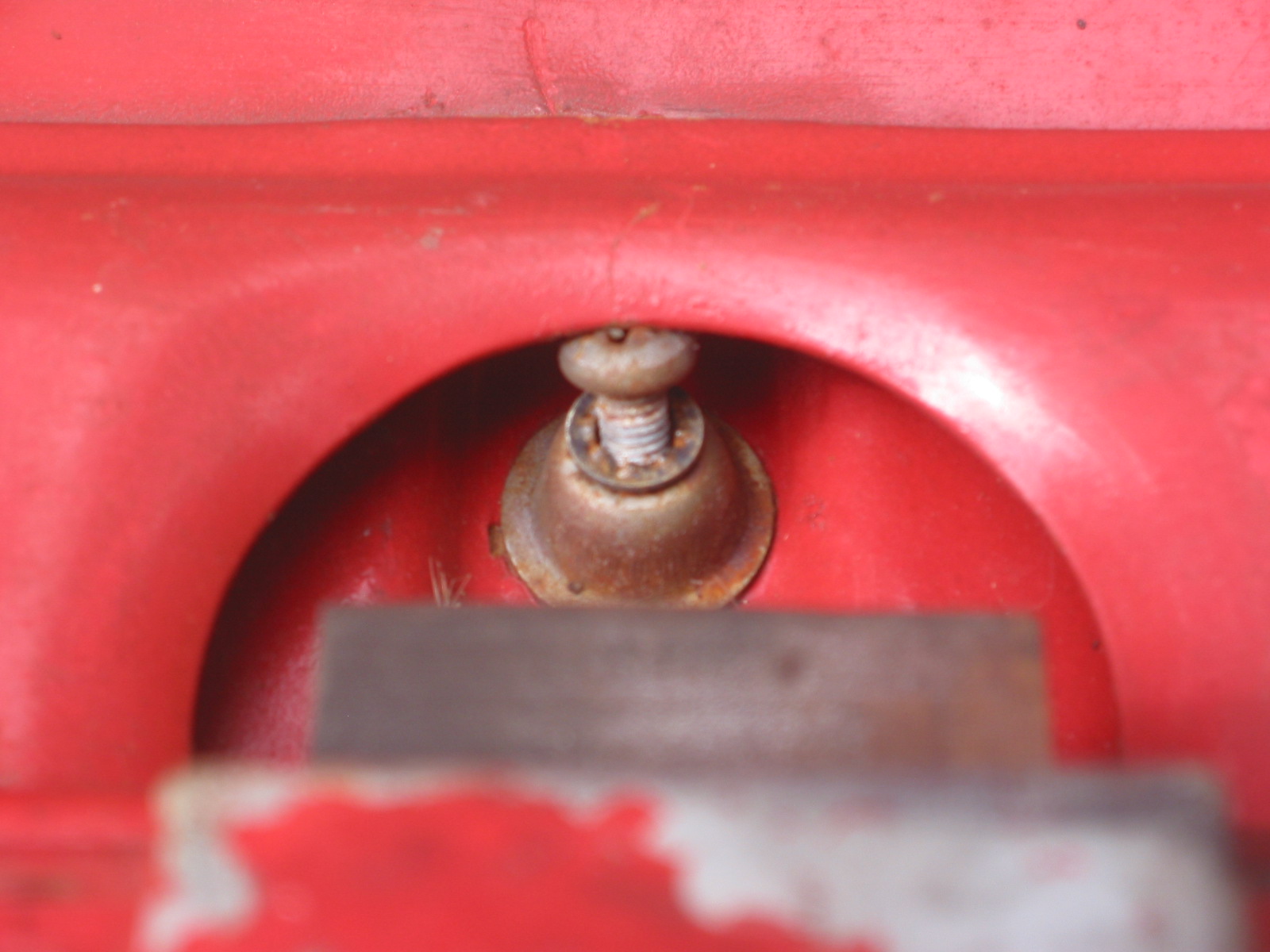
Bump Box
Boot Tire Buffer
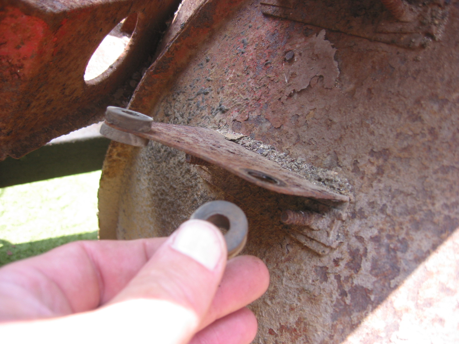
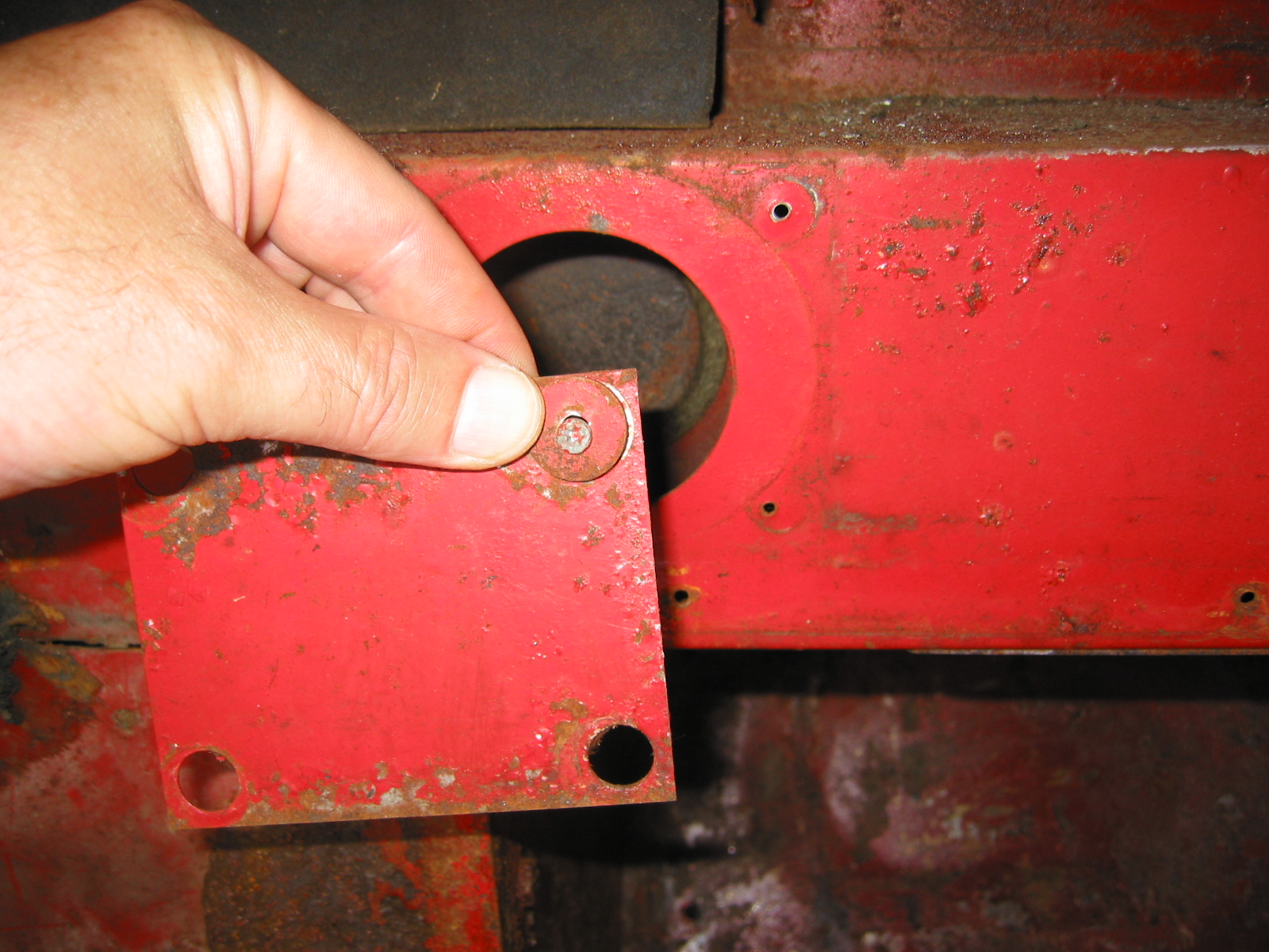
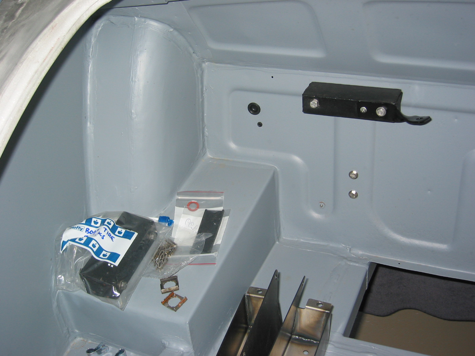
Insulation Panels – Some of the mounting holes for the heat insulation panels on the firewall and footwell were also not drilled. We located the proper locations, drilled the holes and mounted the panels without difficulty.

Insulation 1
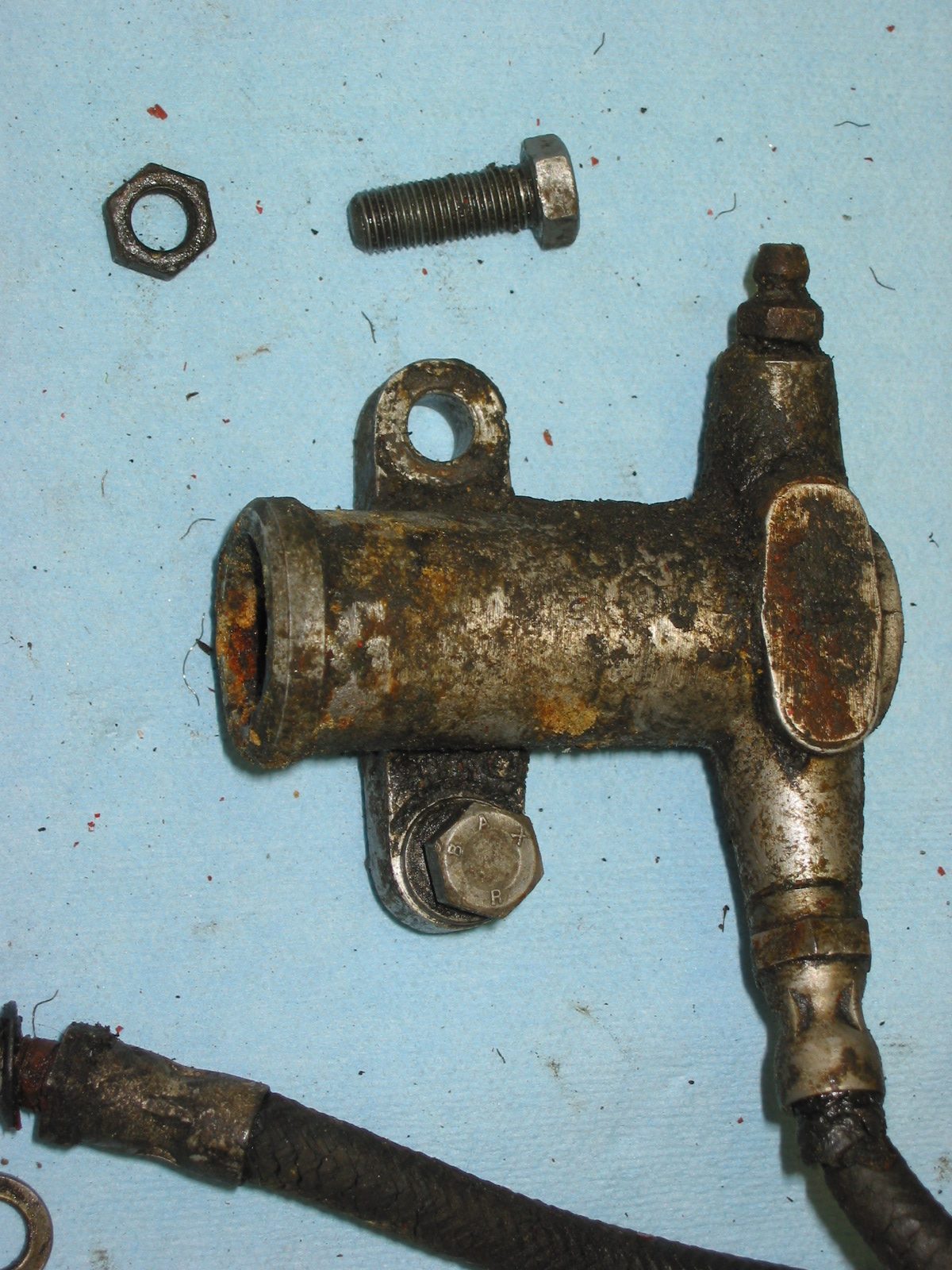
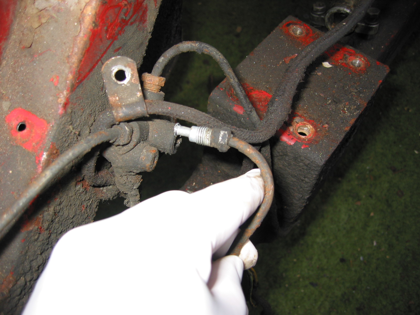
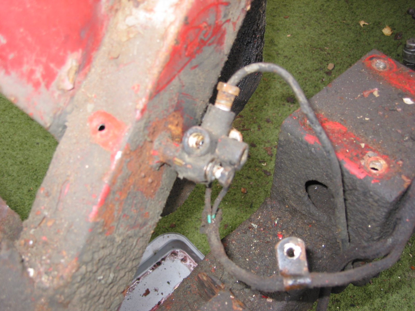
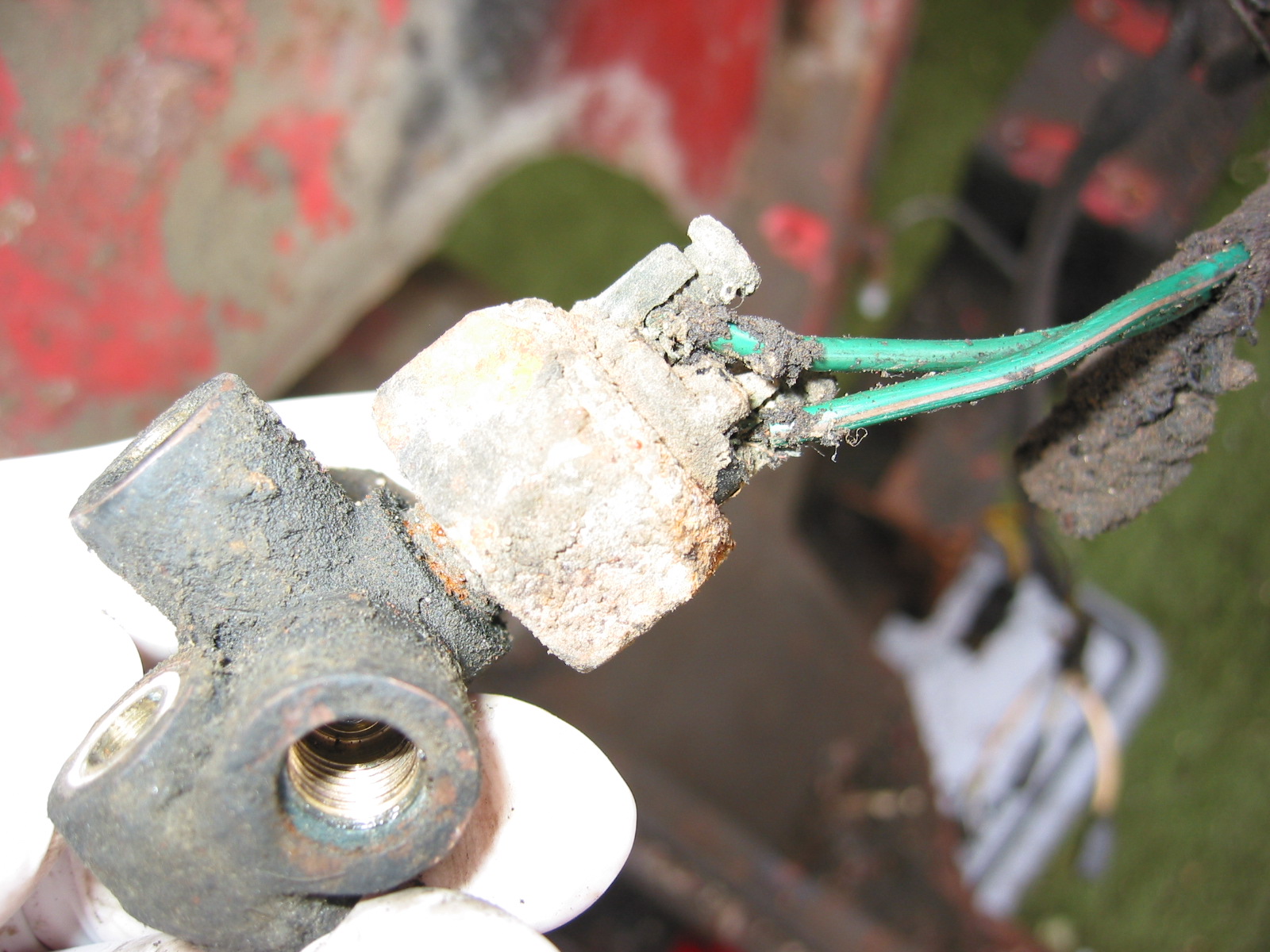
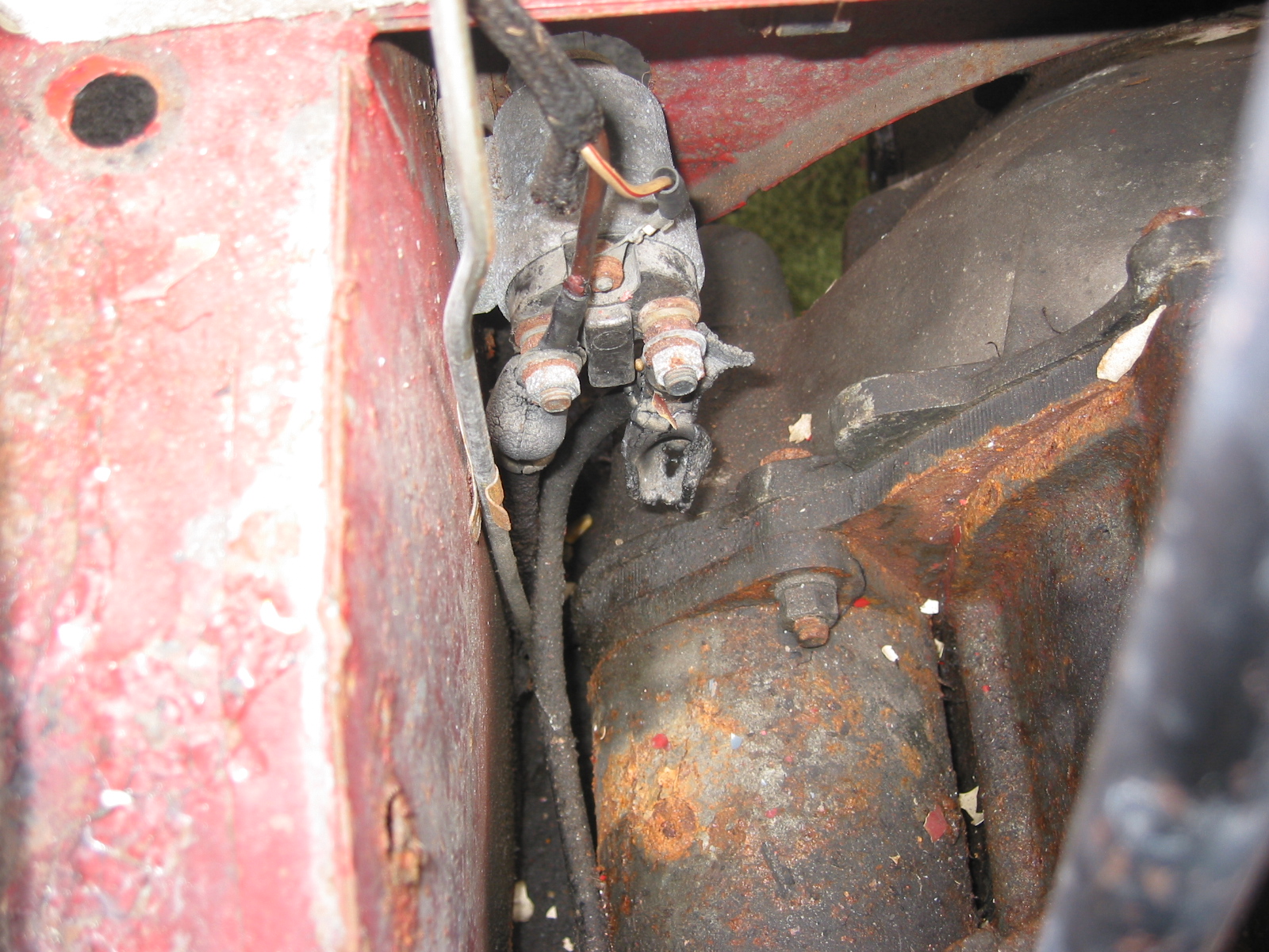
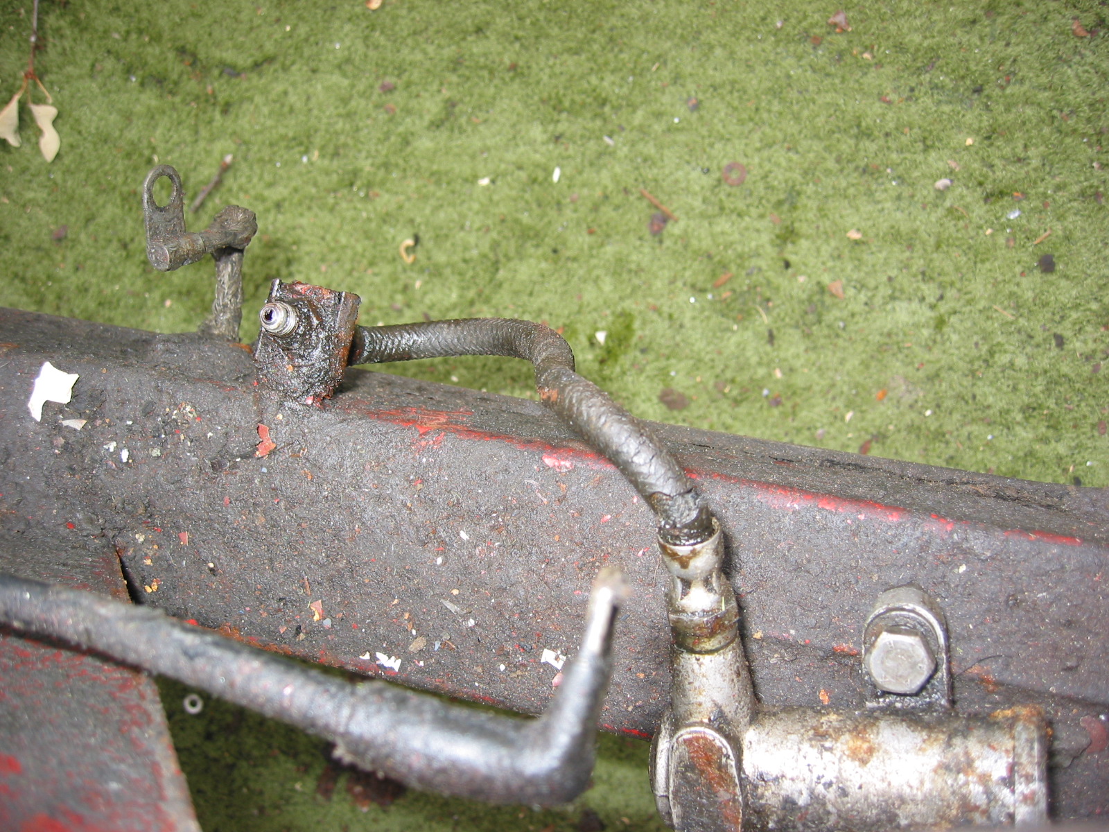
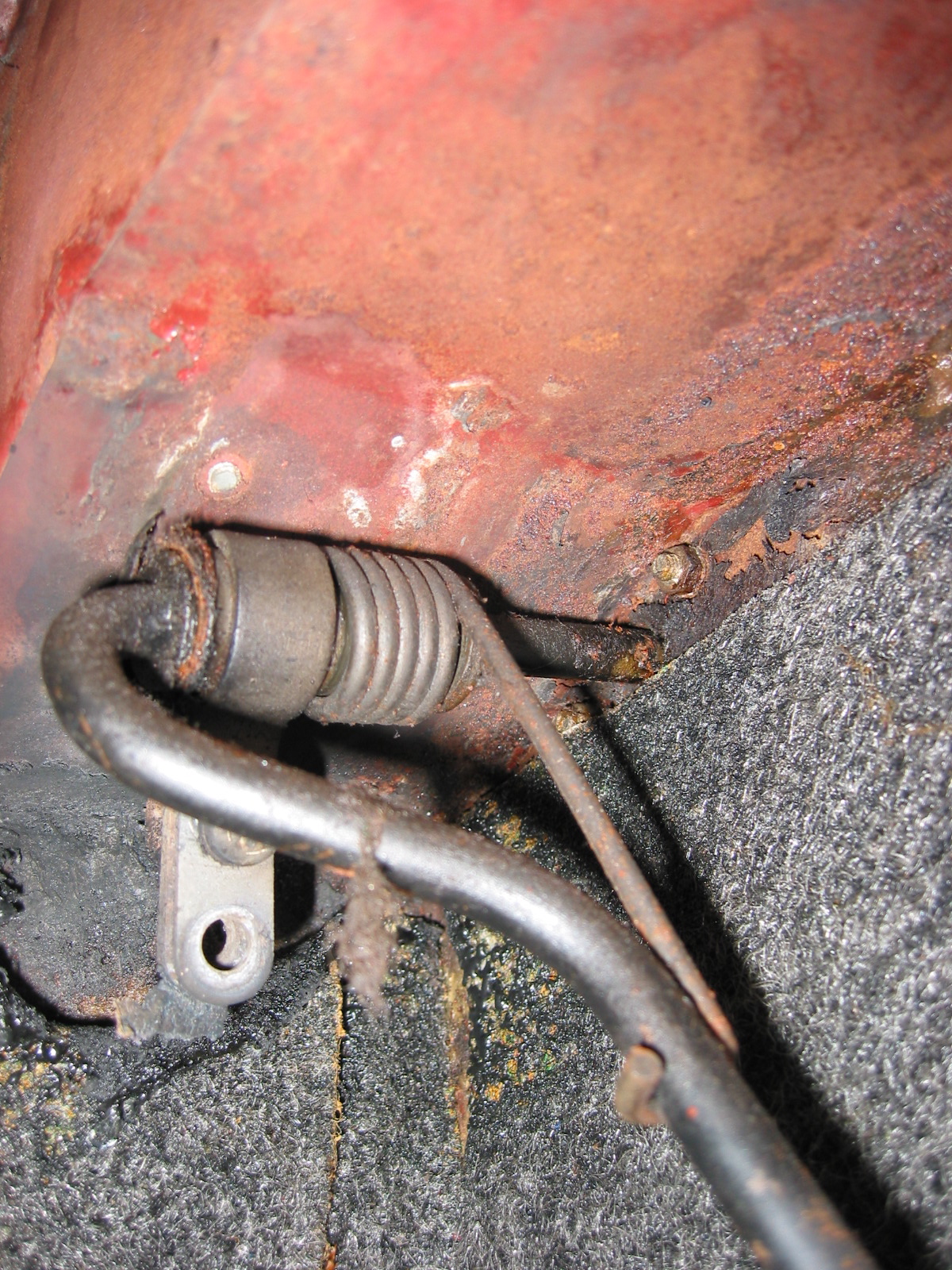
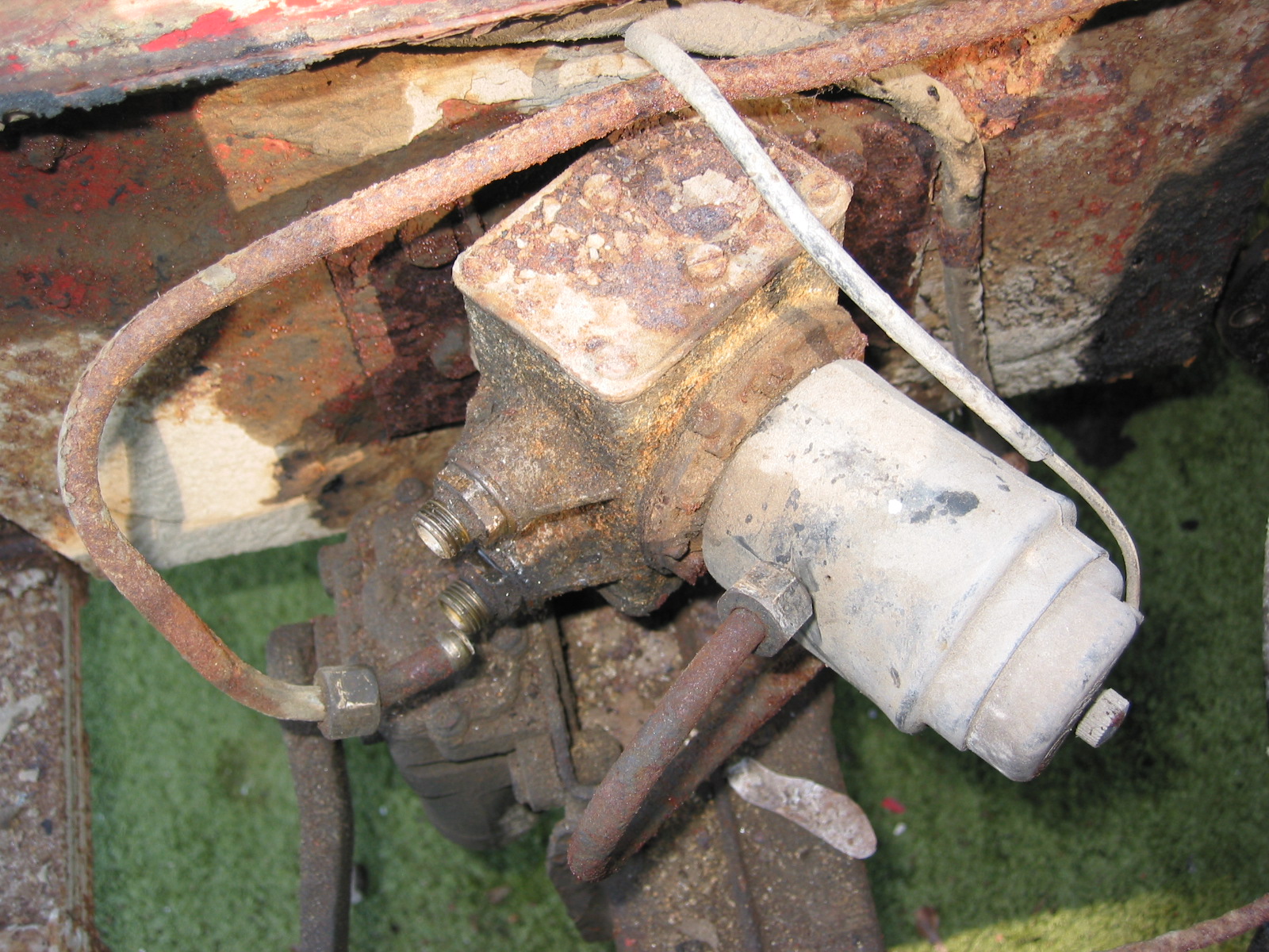
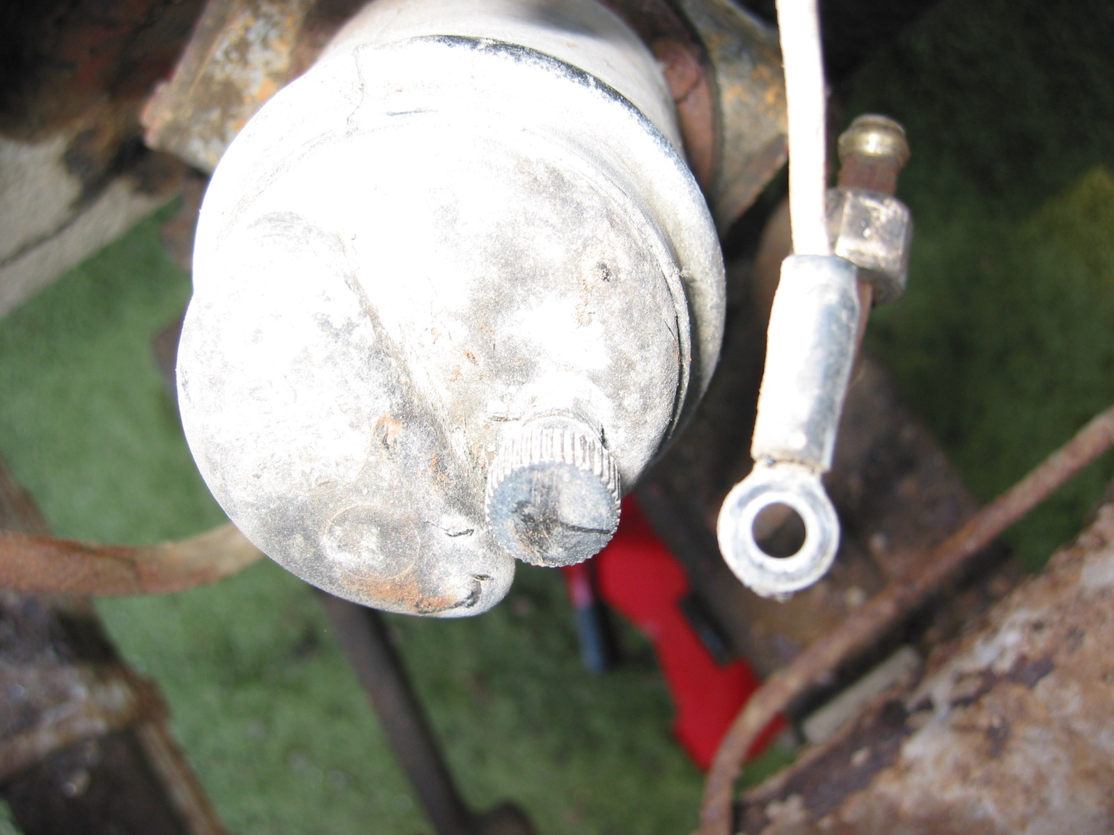
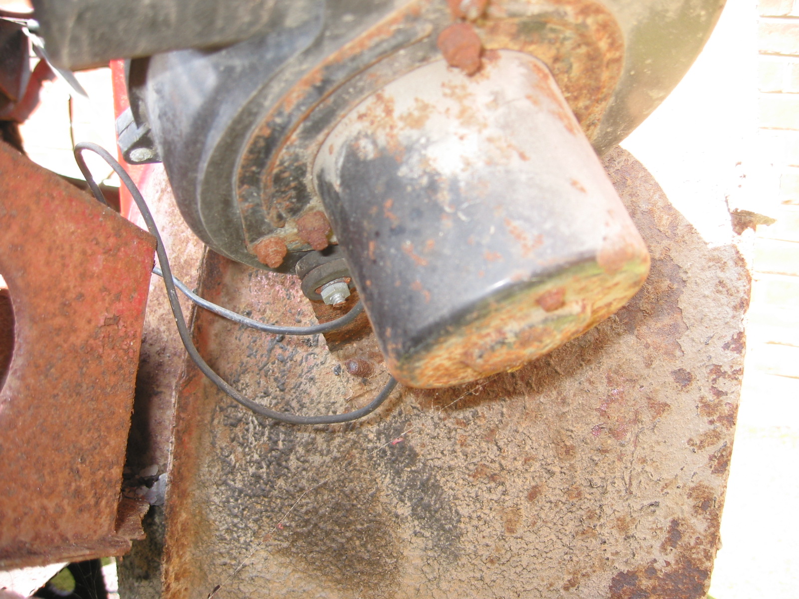
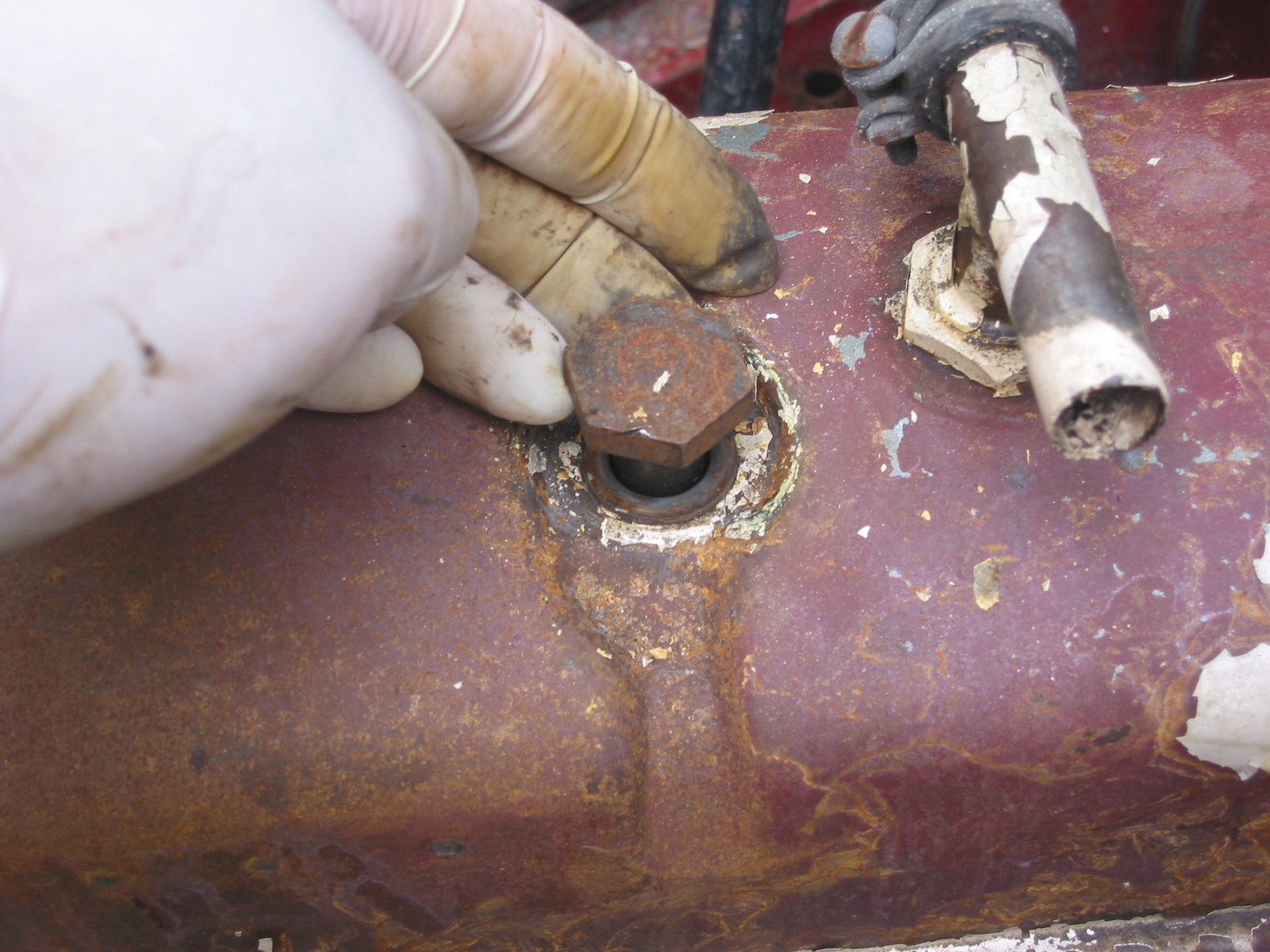
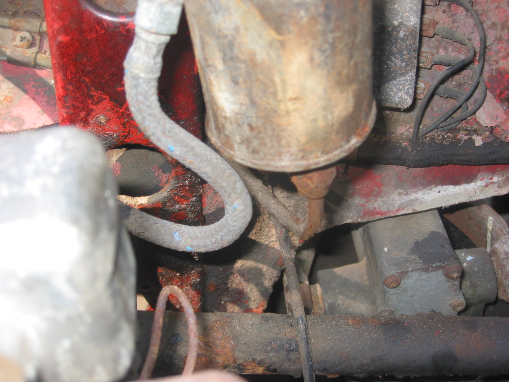
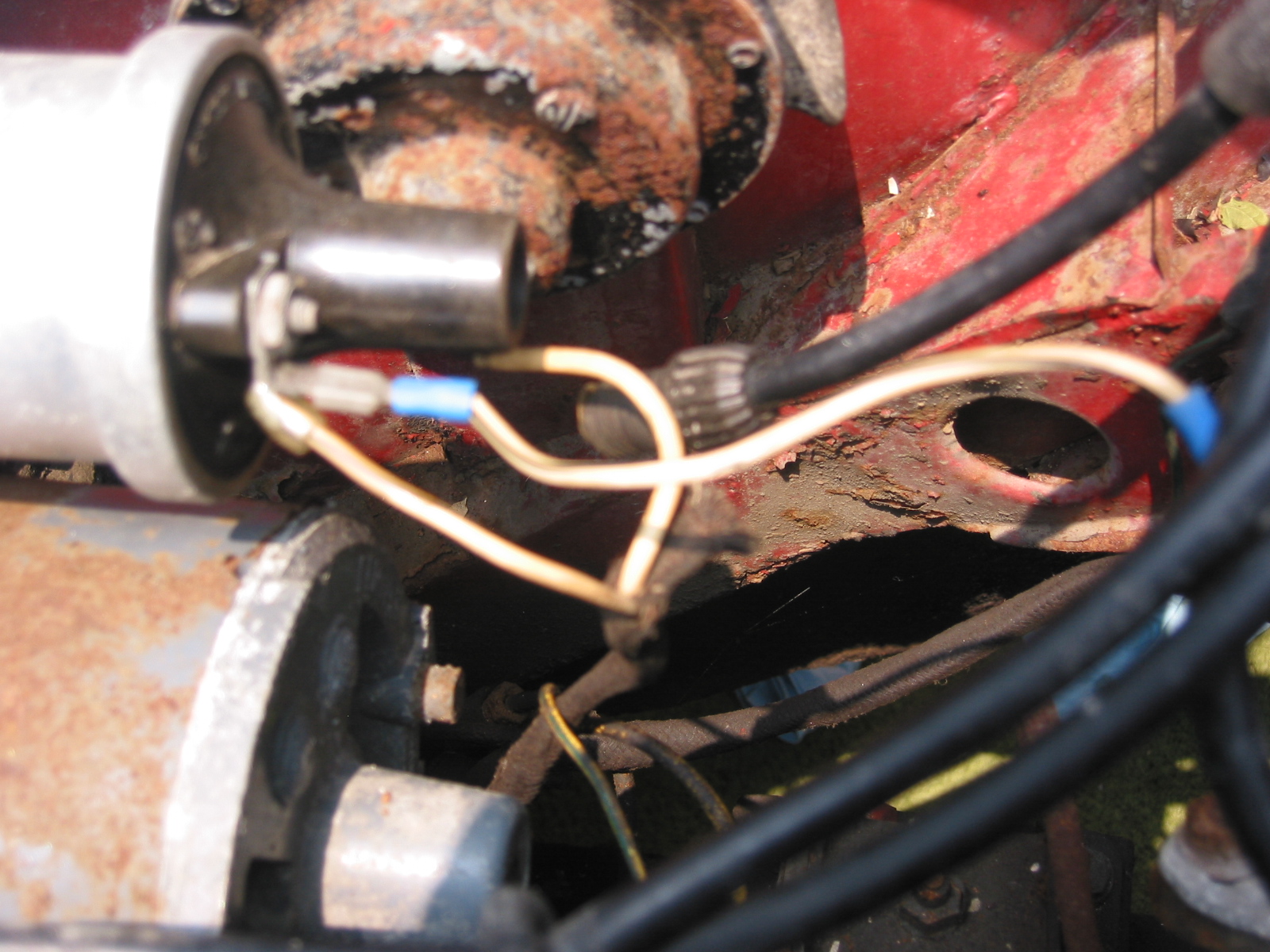
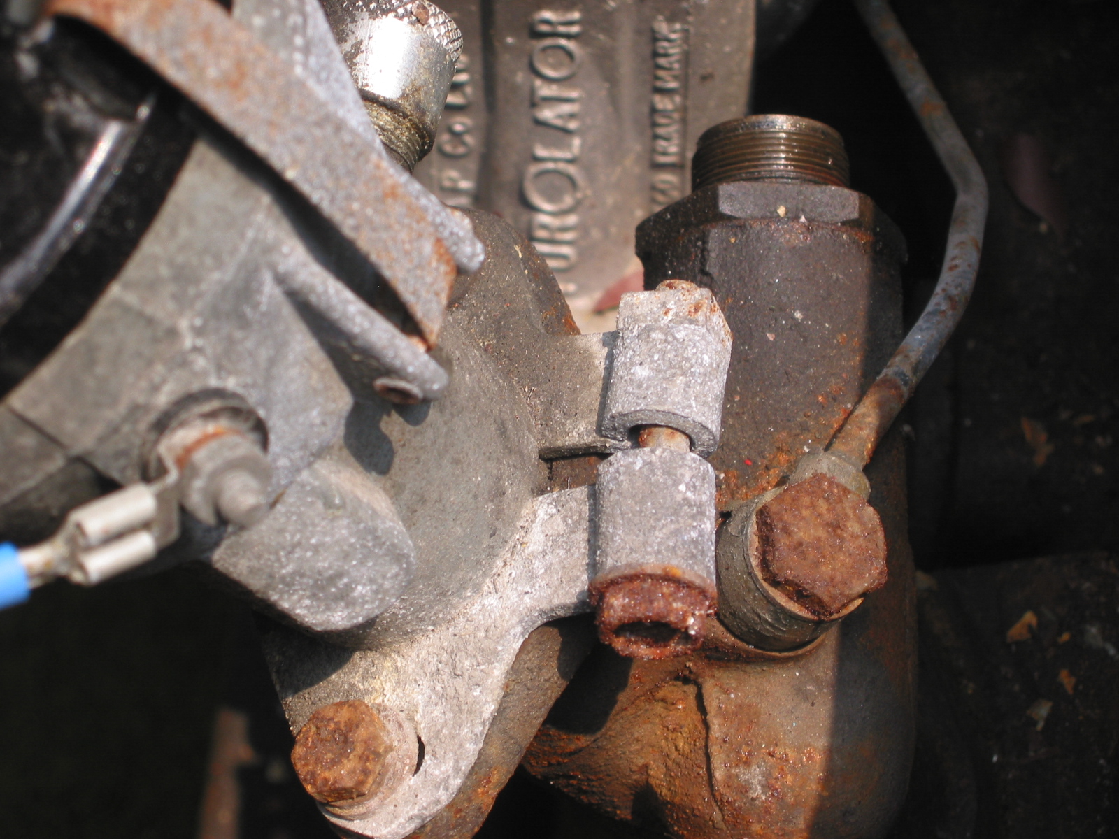
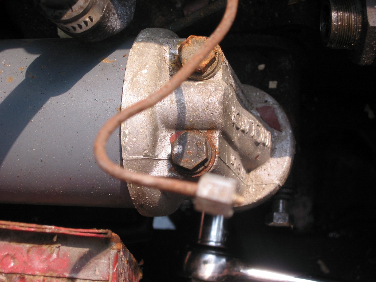
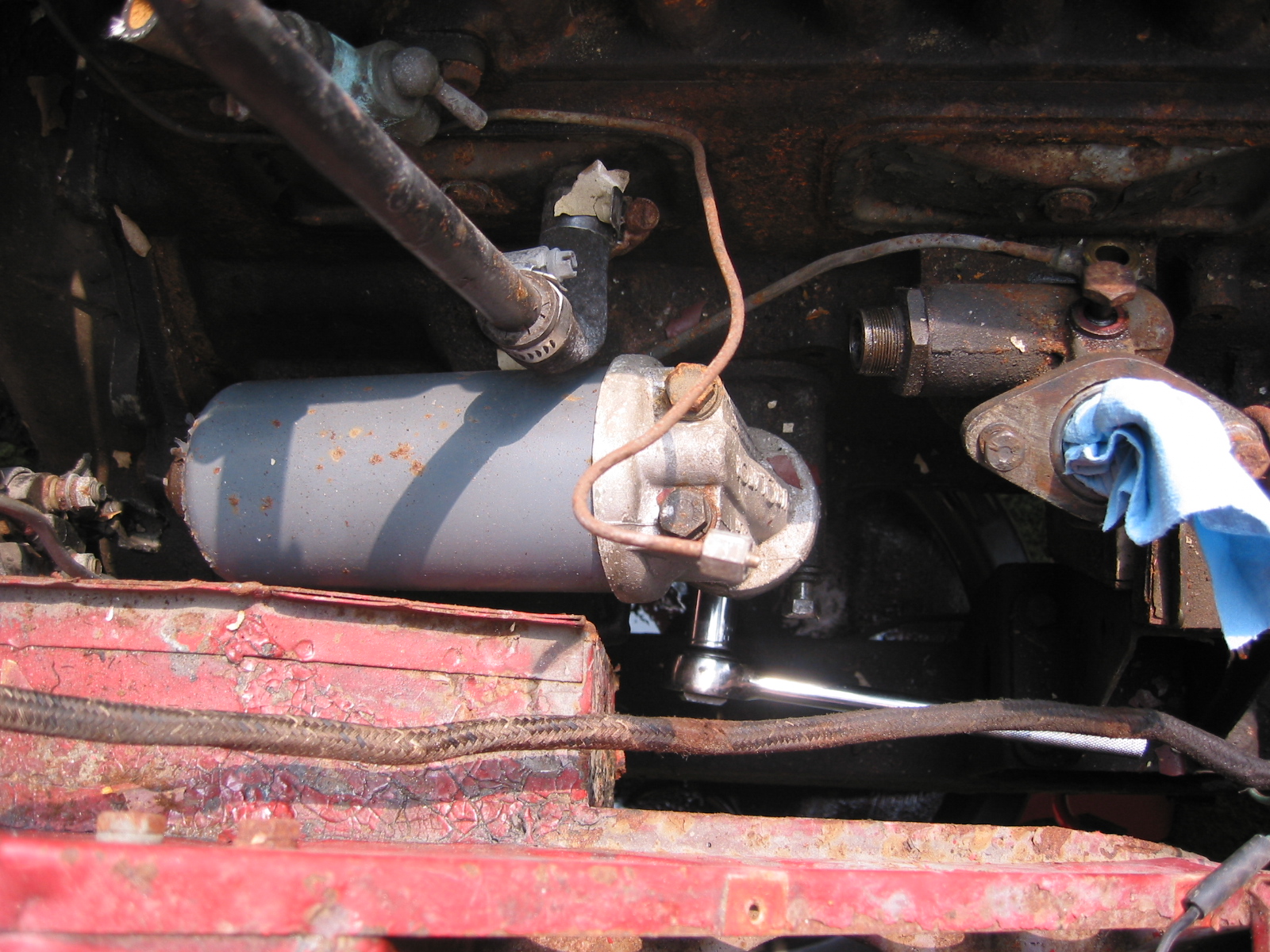
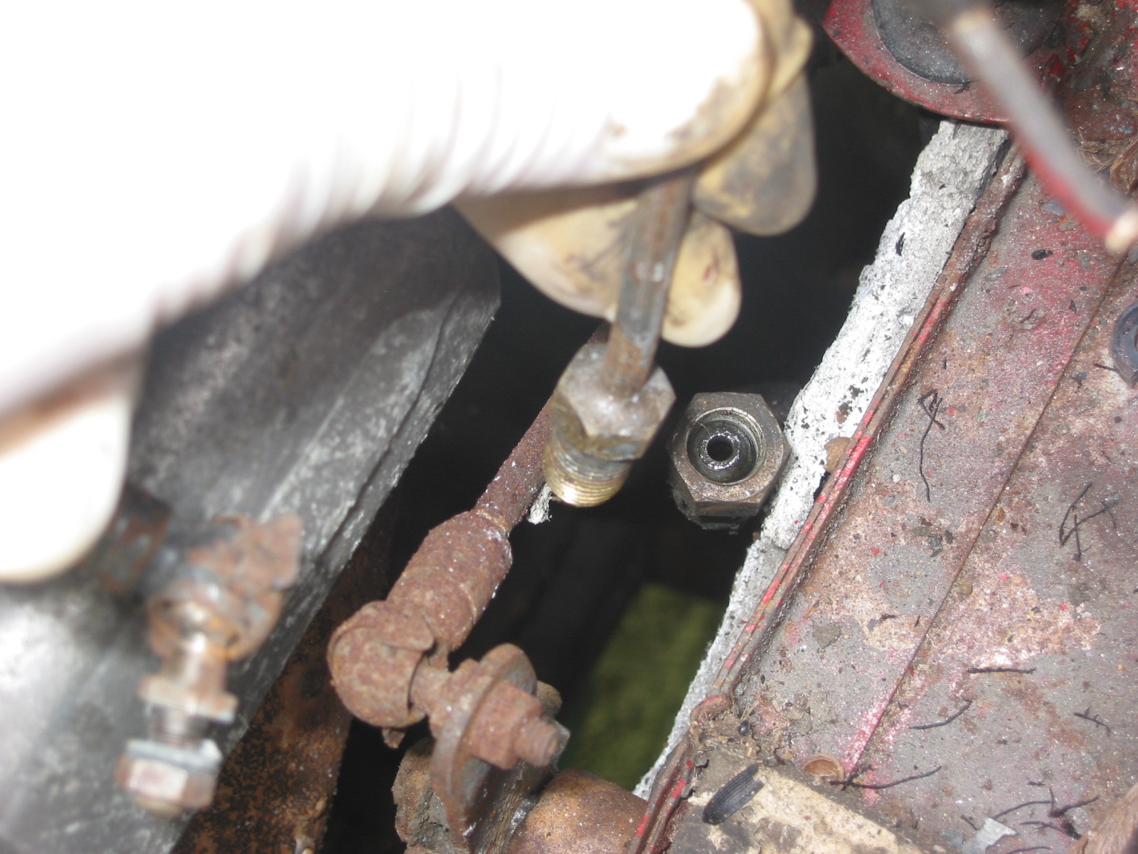
The Oil Pressure Line – The line was located and installed although new clips will be ordered.
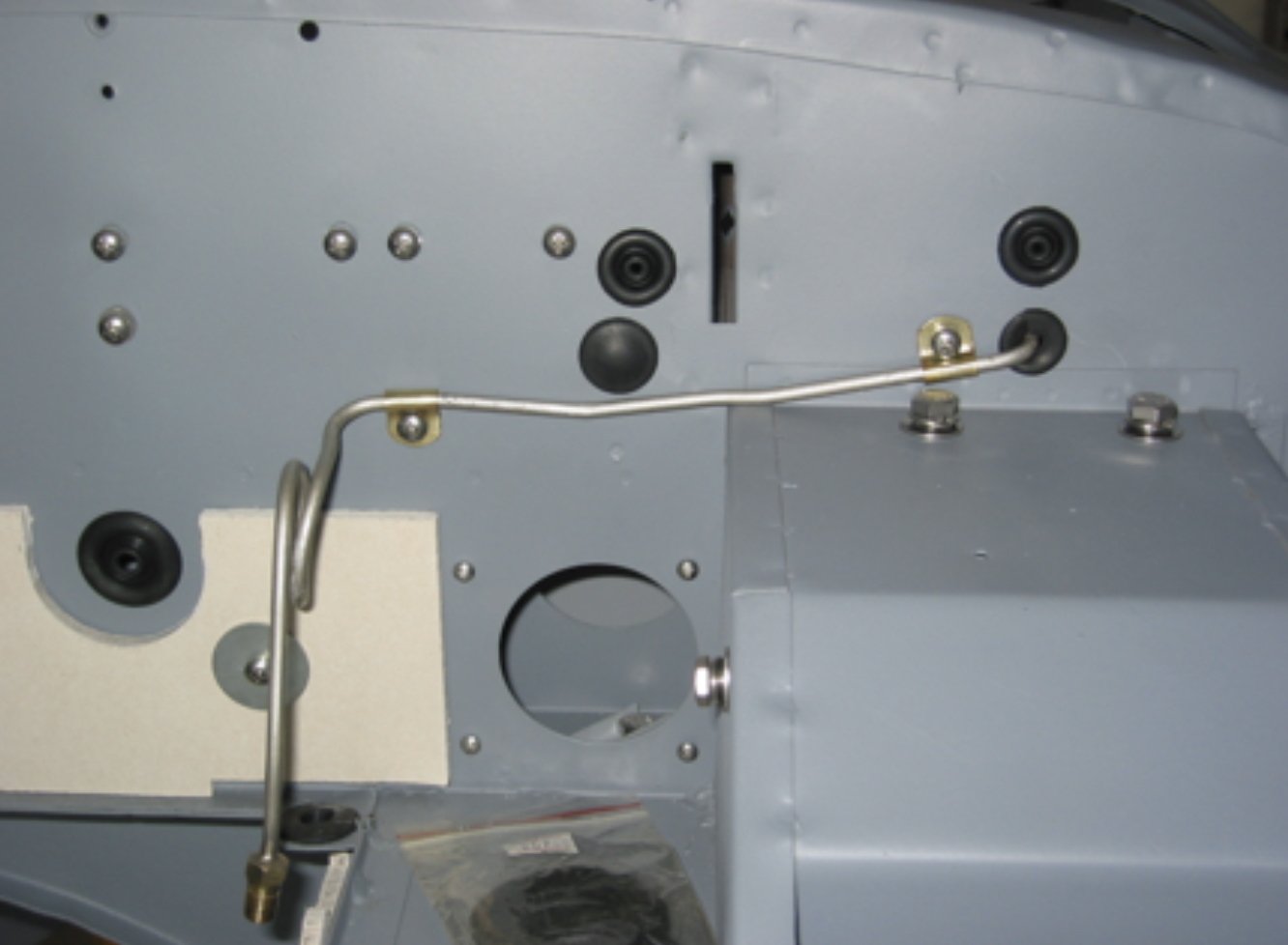
Oil Line
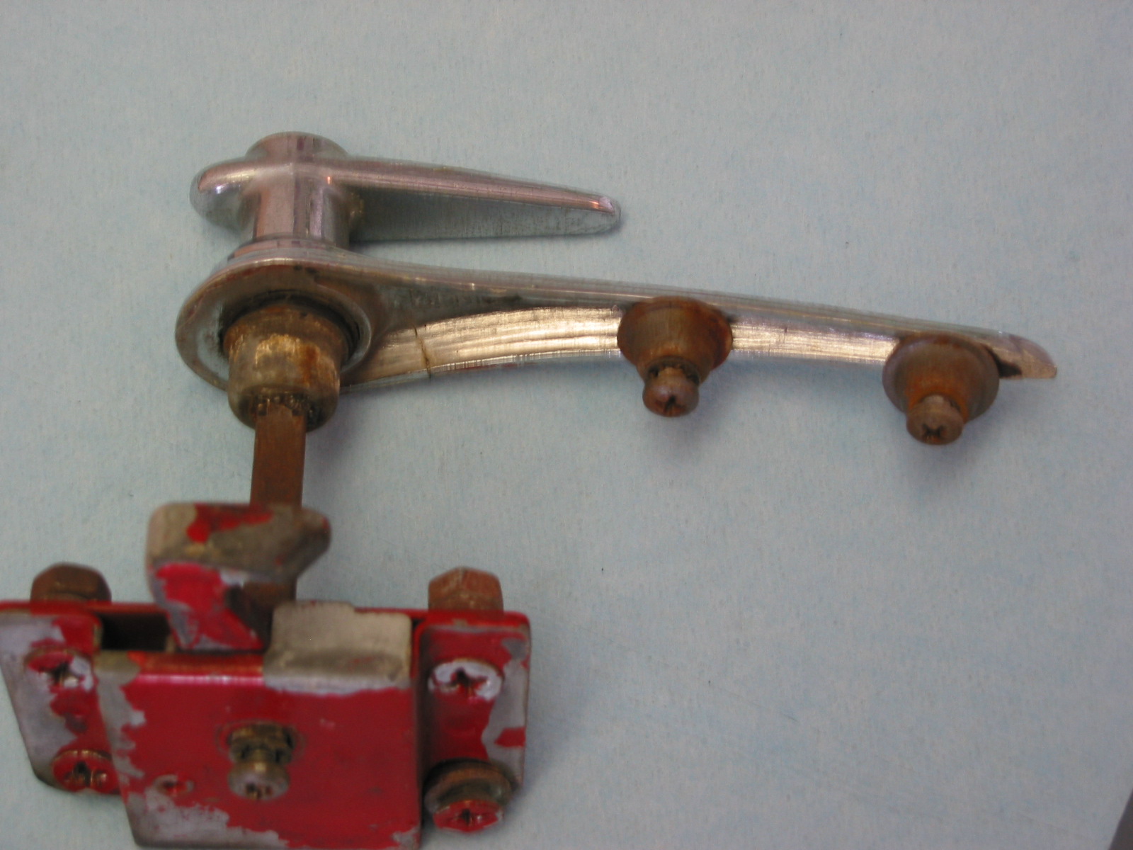
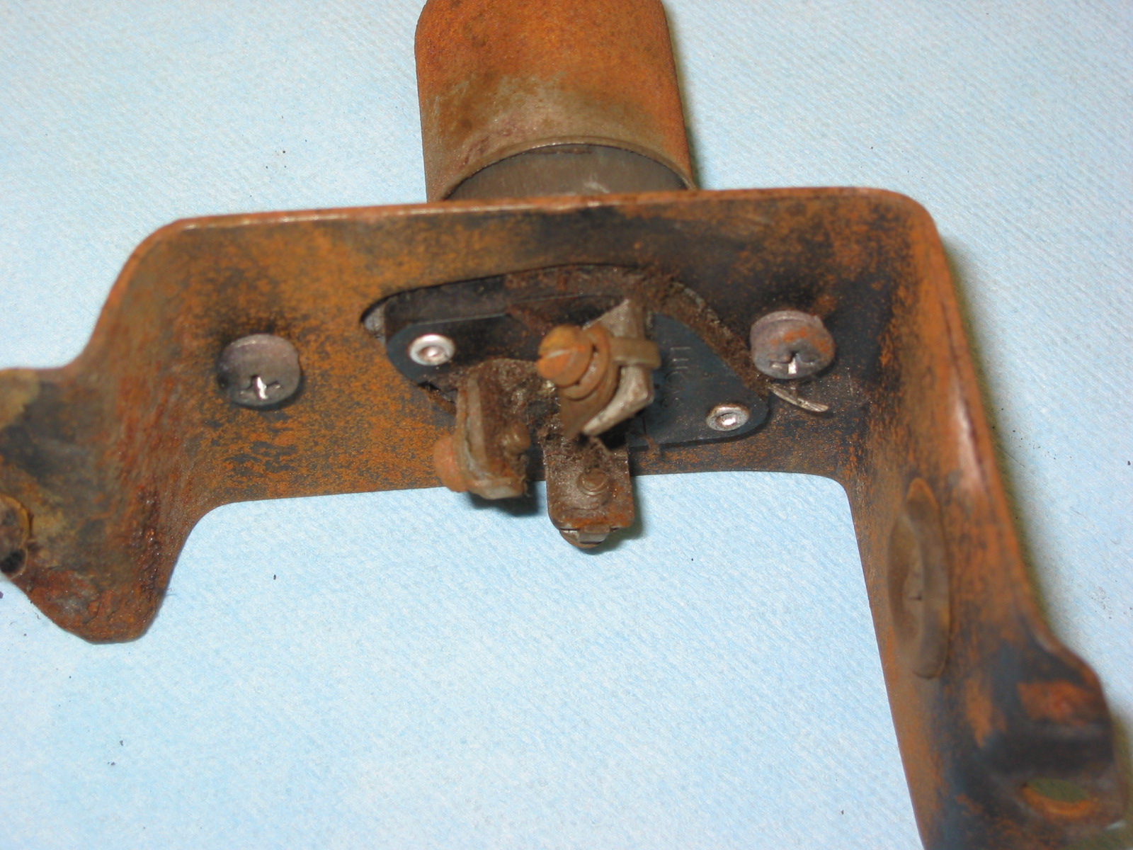
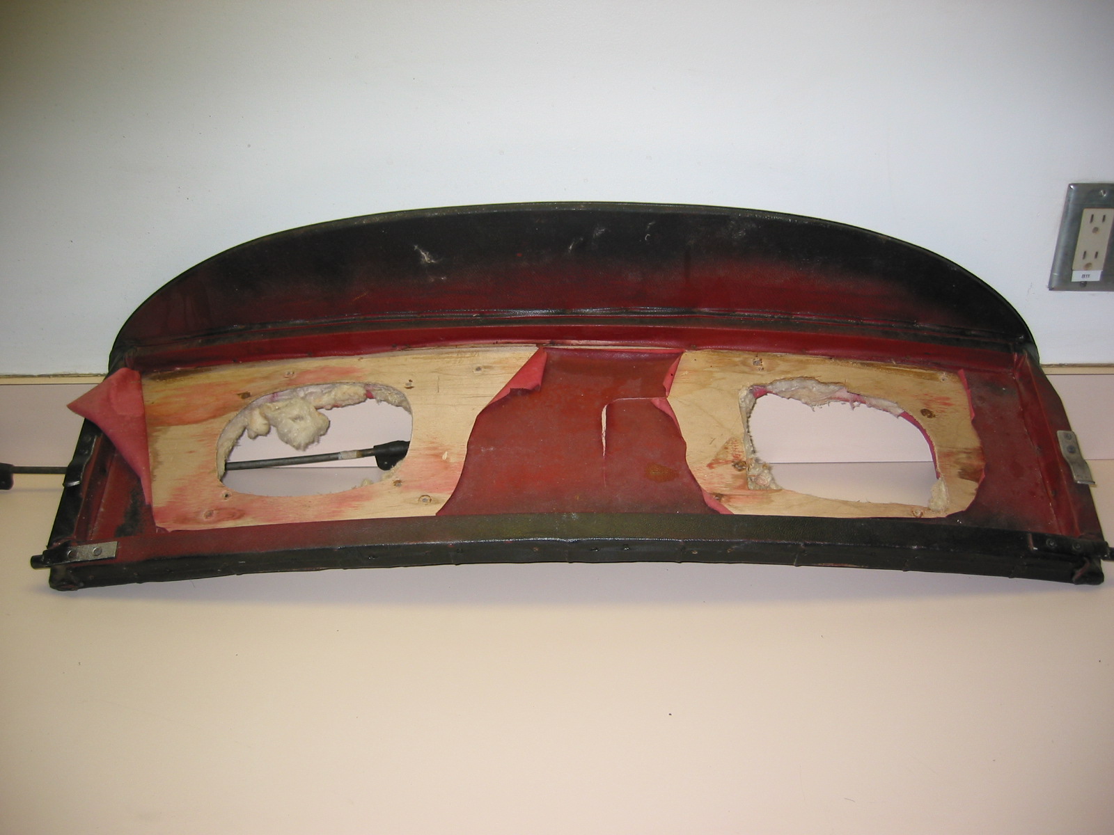
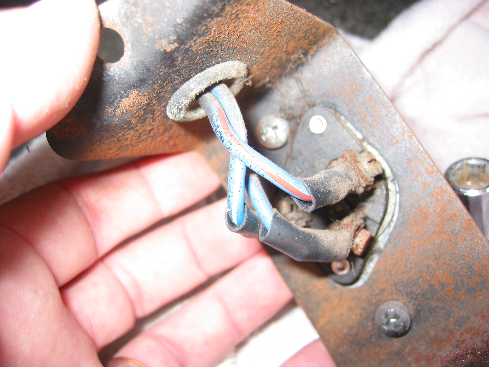
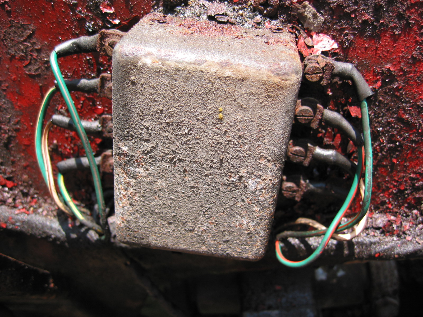
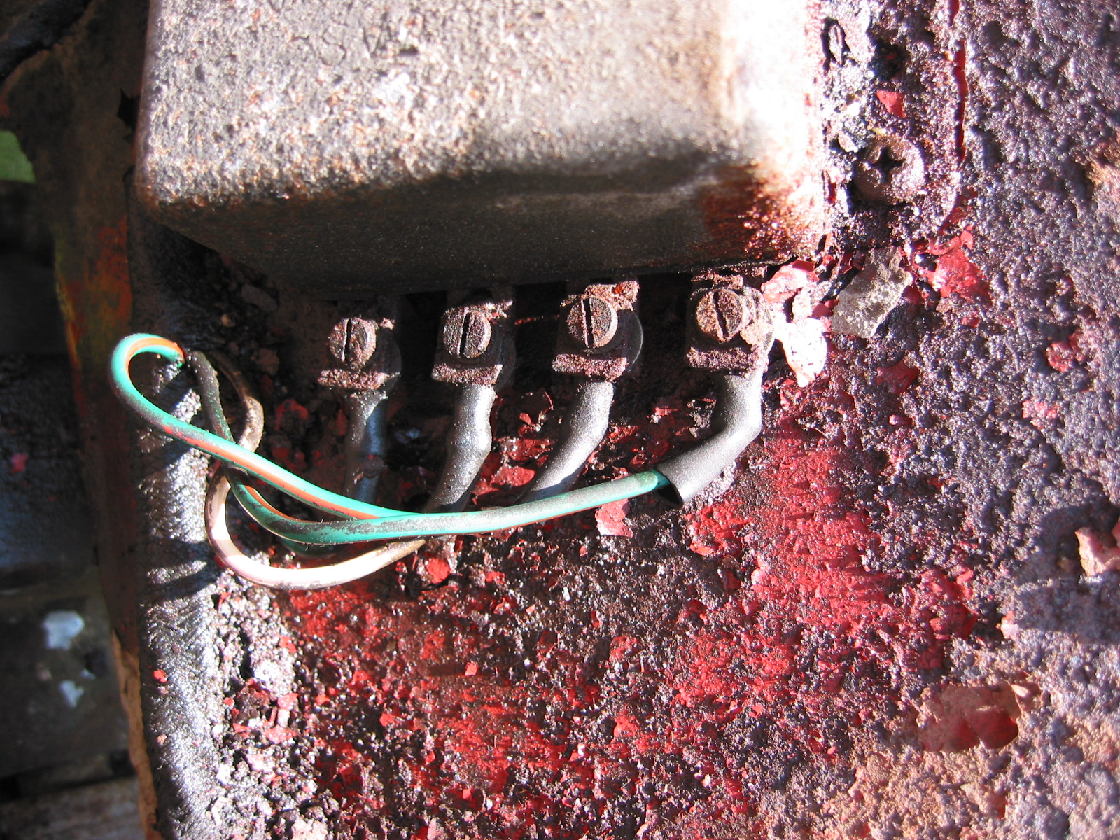
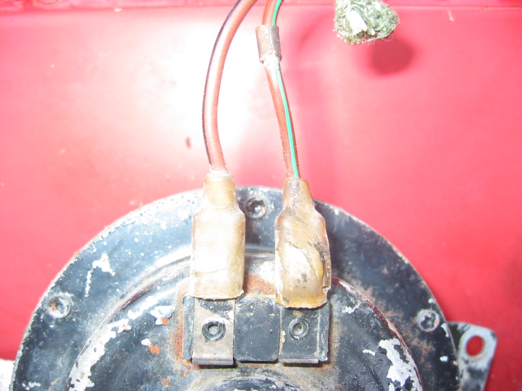
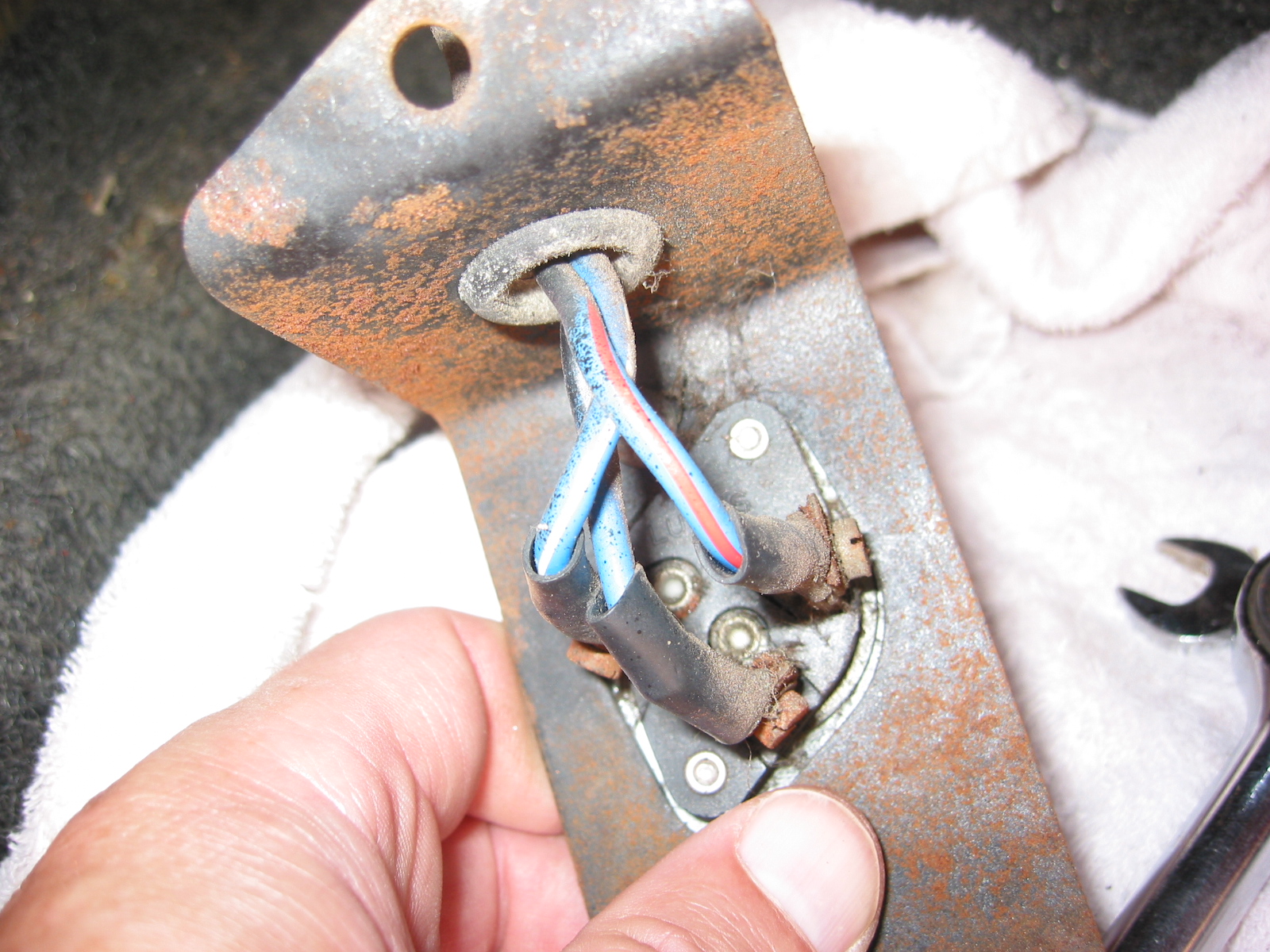
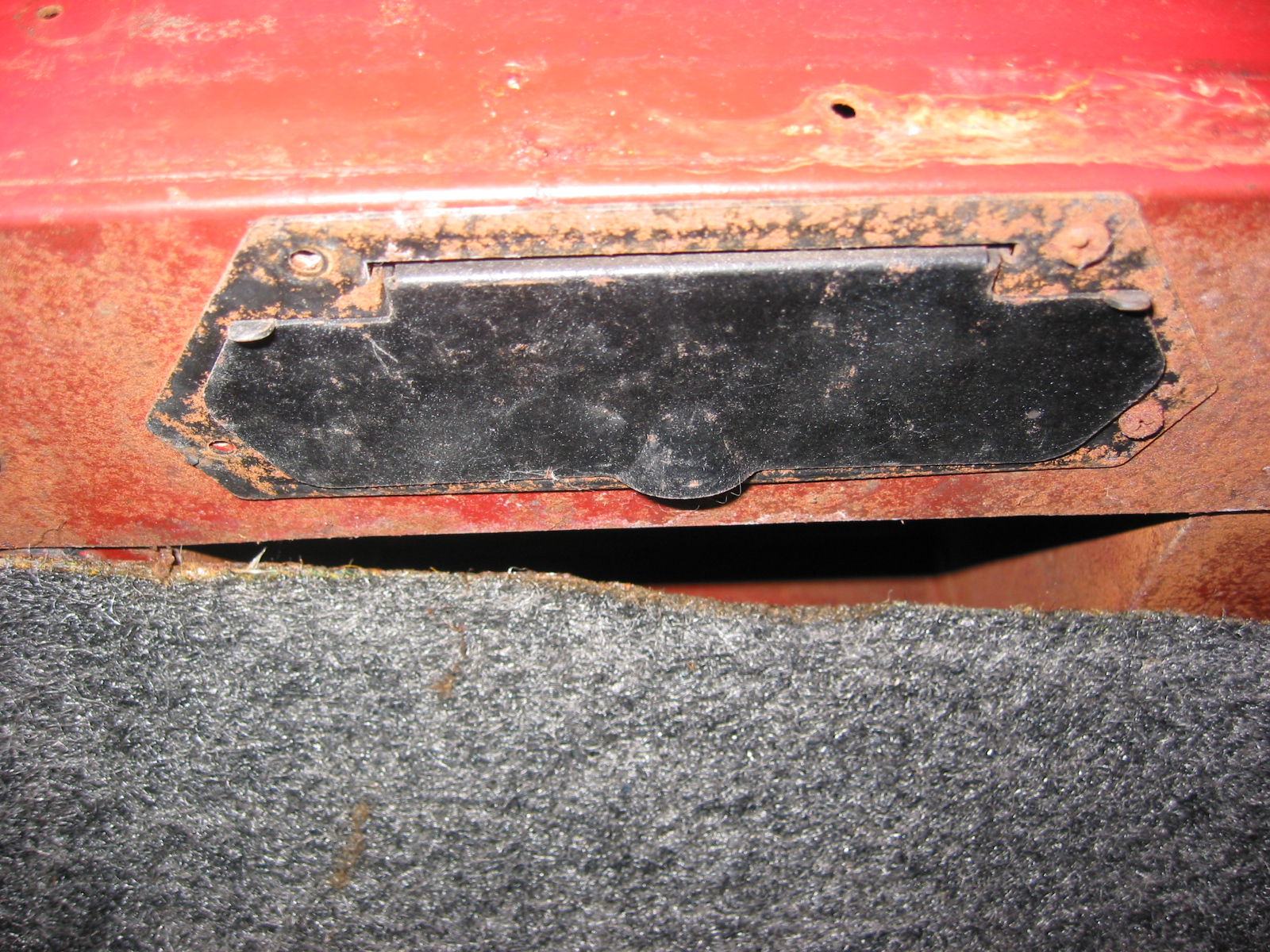
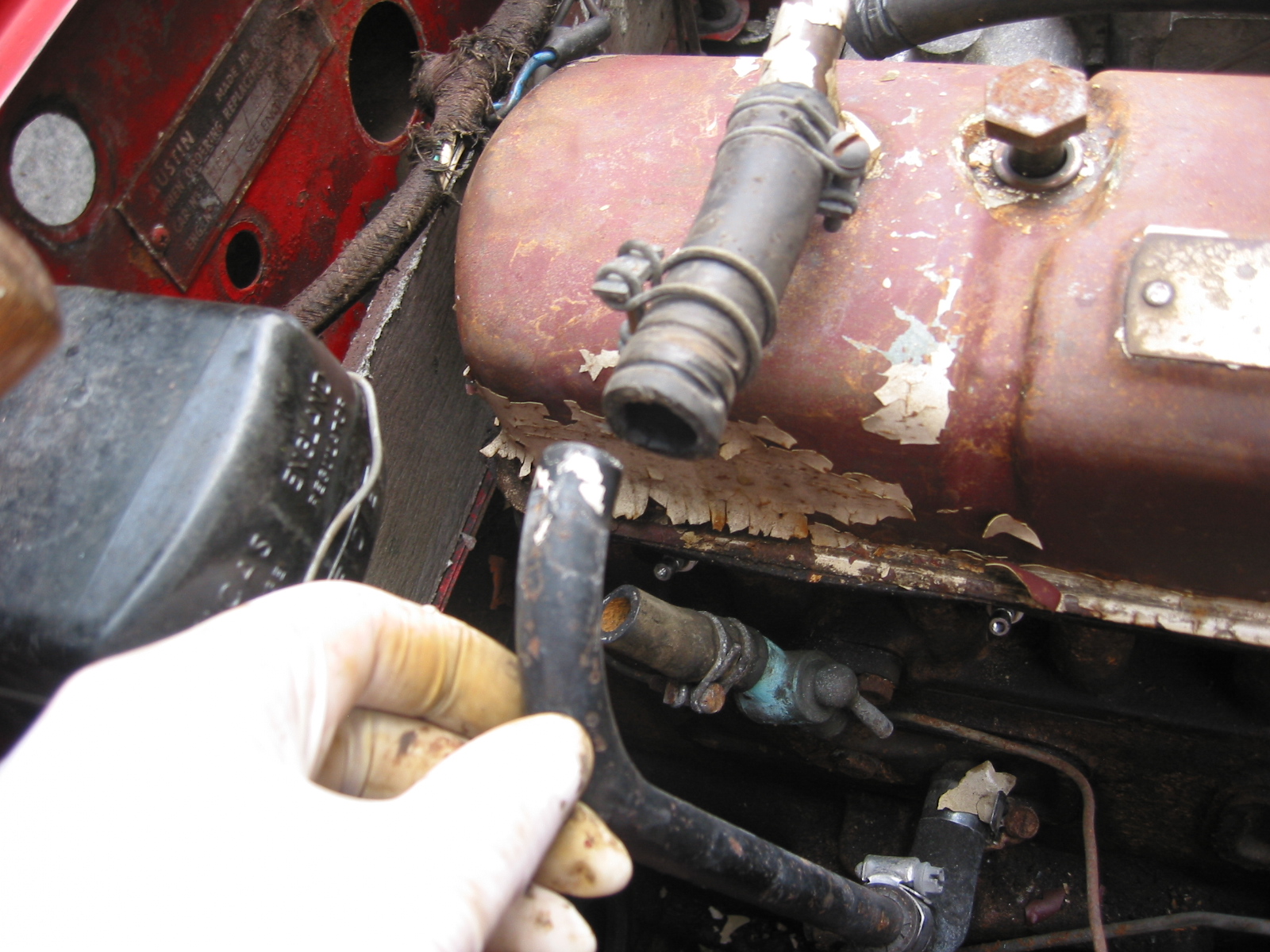
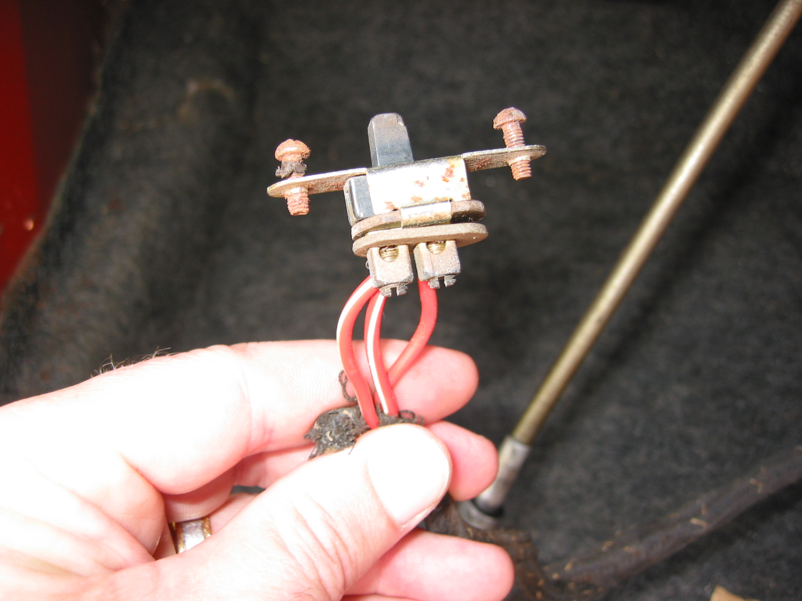
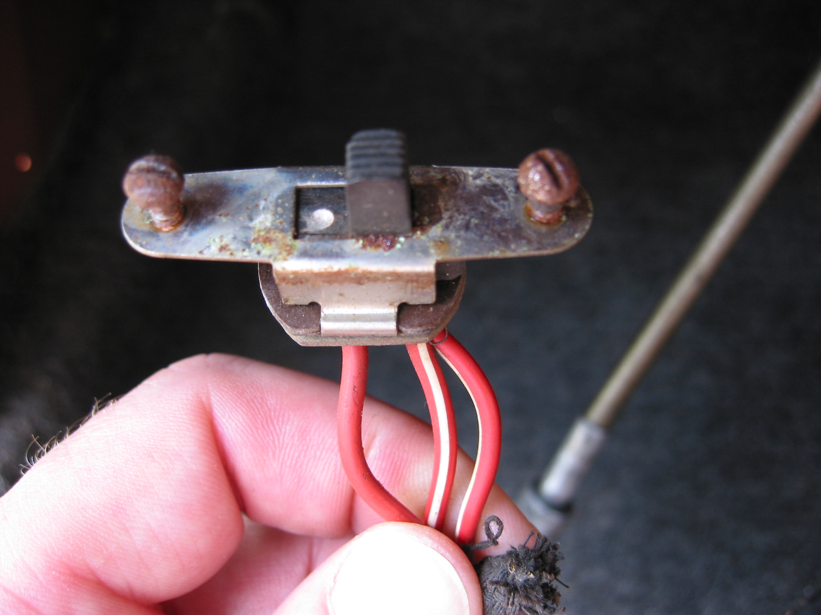
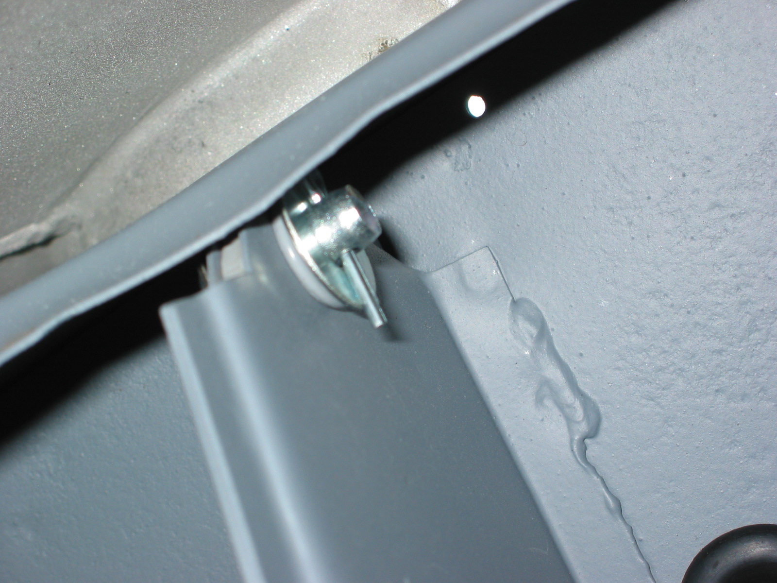
The Dip Switch and Parcel Tray – These components were also located and installed. Note the original water bottle.

Parcel Tray & Bottle
Installed dimmer switch
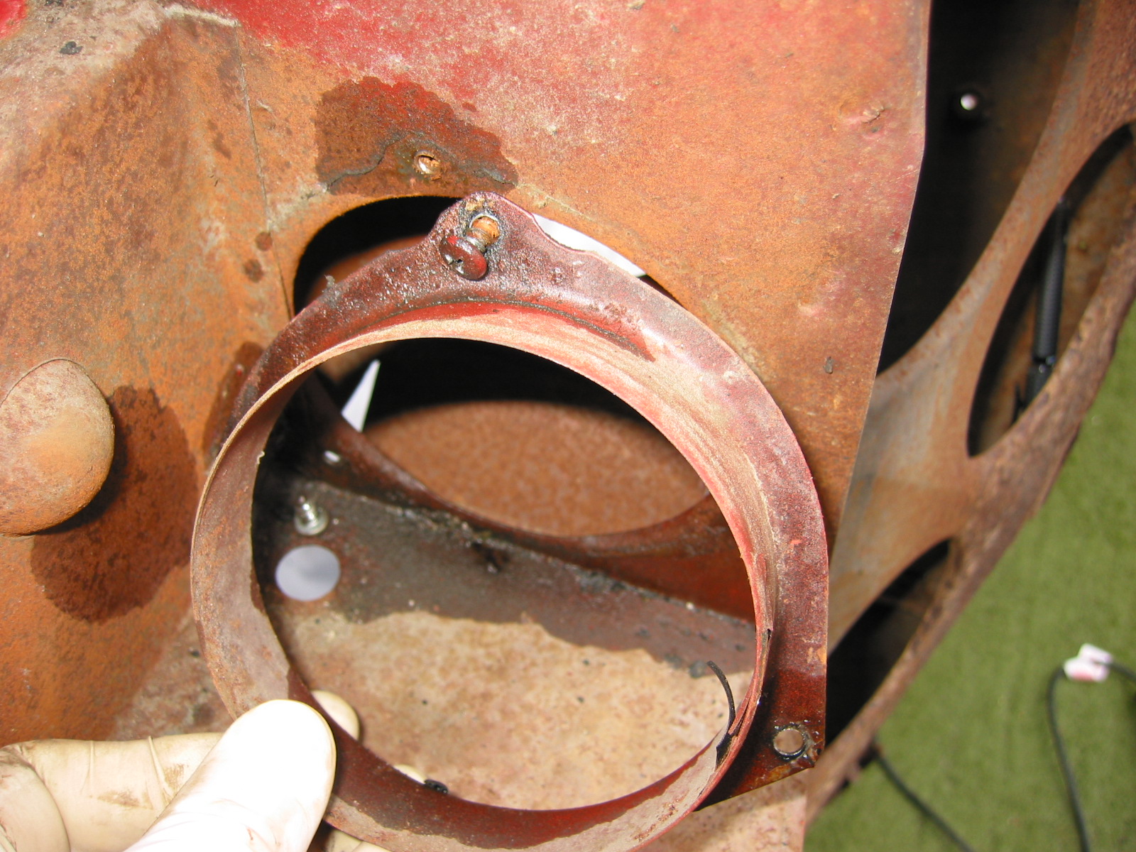
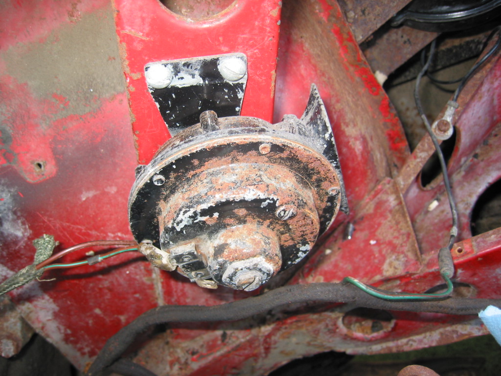
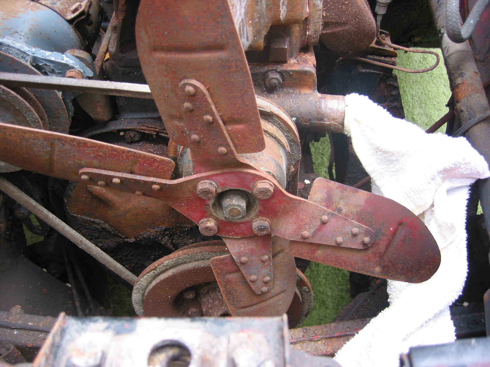
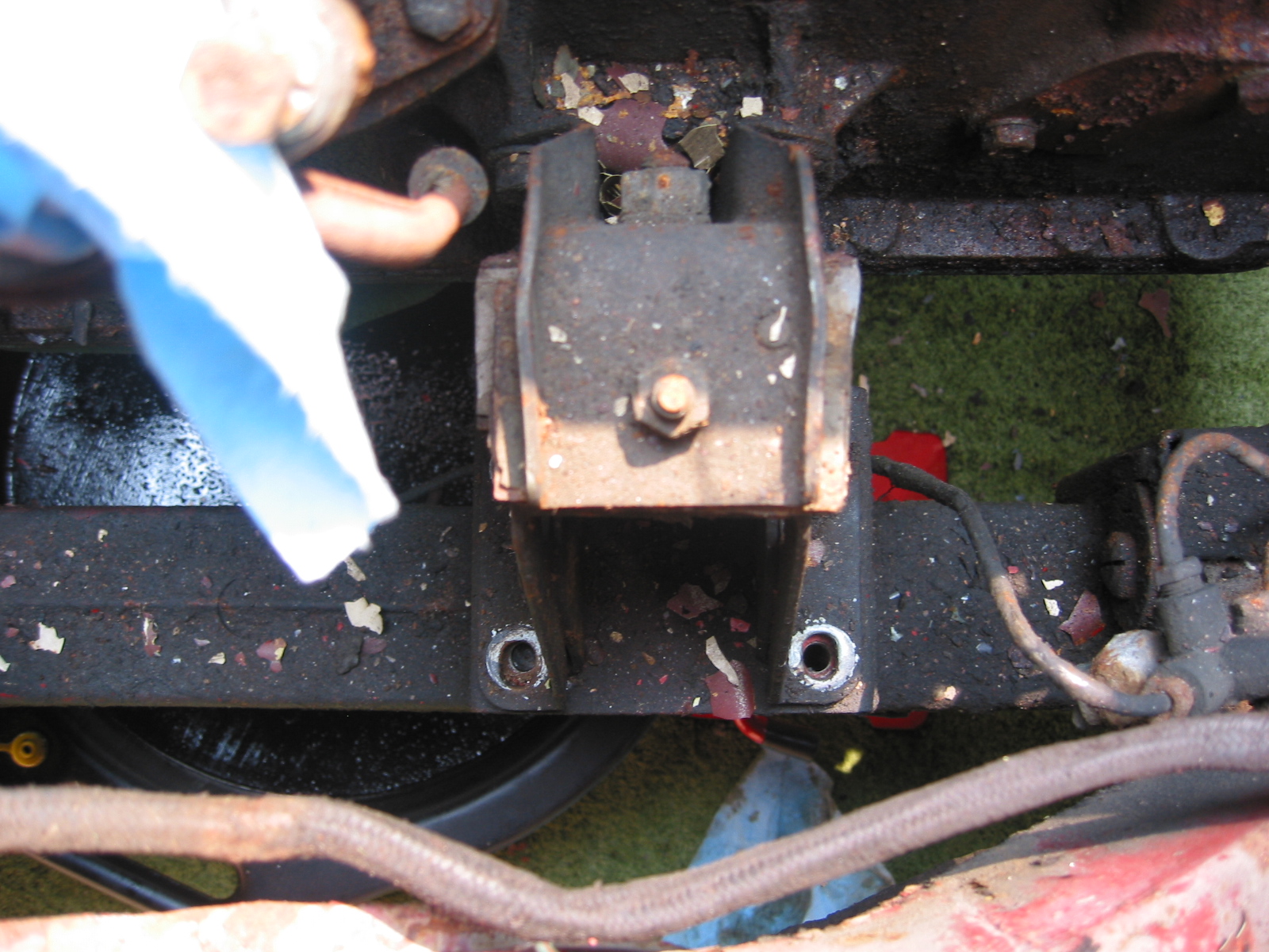
Radiator Brackets – The brackets were cleaned and painted and were installed on the crossmember, and the painted air intake flange.
Radiator Mount 2
July 23, 2003
Hardware Reassembly
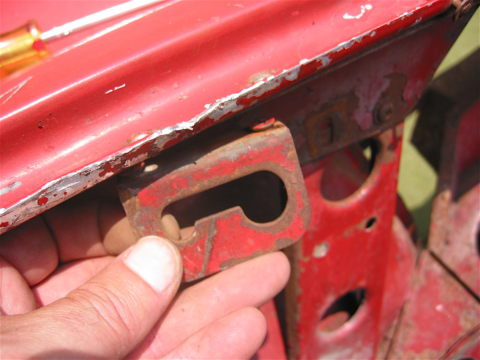
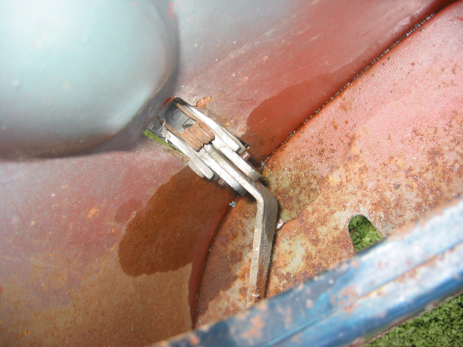
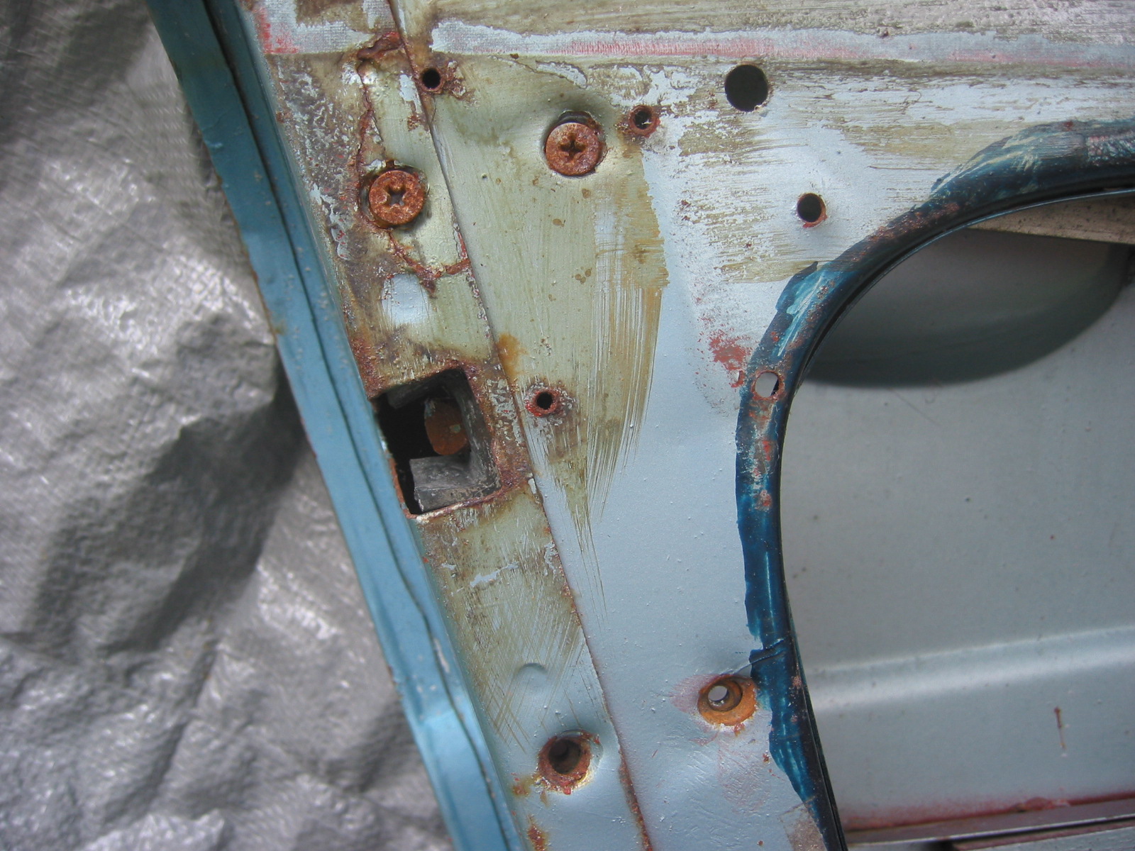
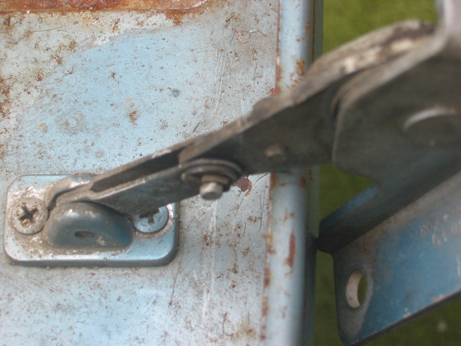
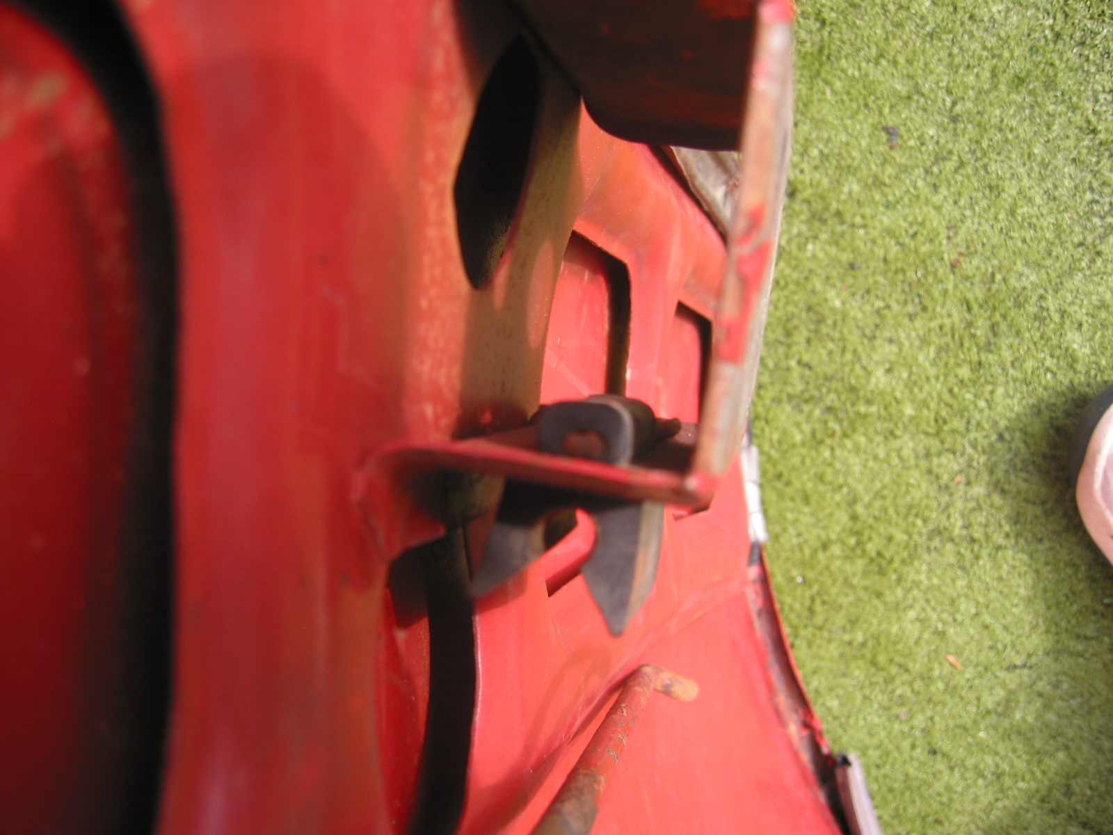
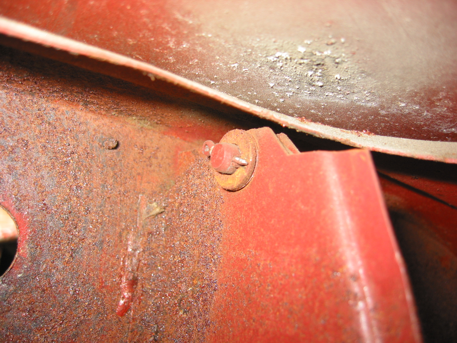
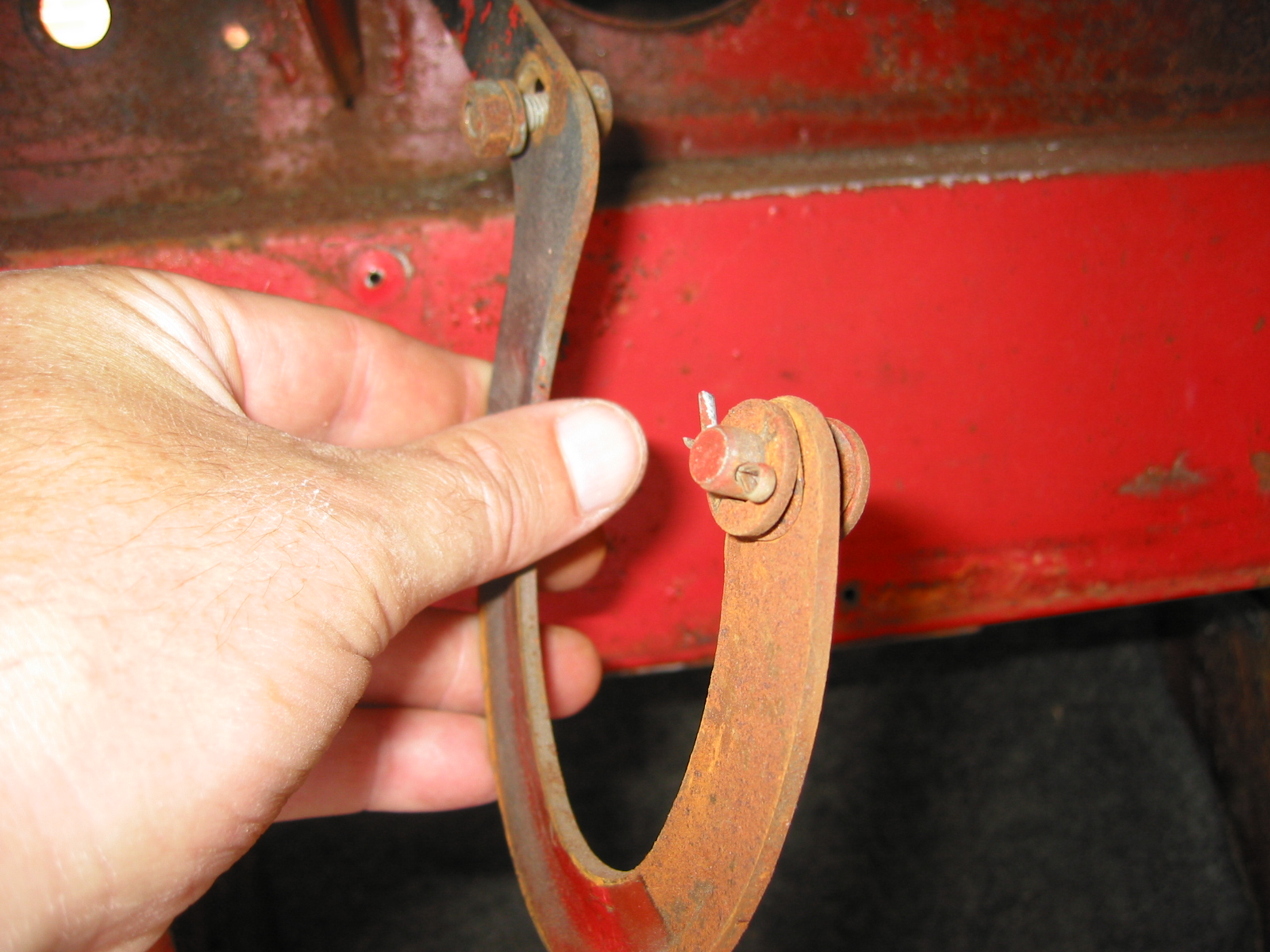
Door Staps – The original door straps (catches) were cleaned, re-zinced and installed on the door pillars.
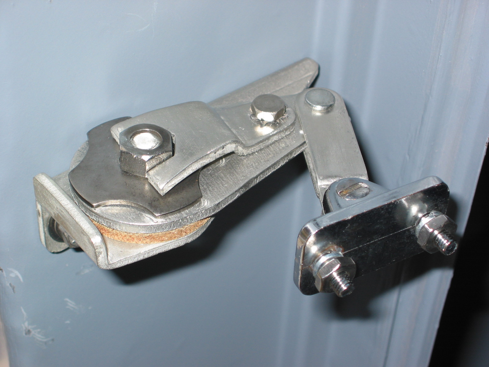
Door Strap 1
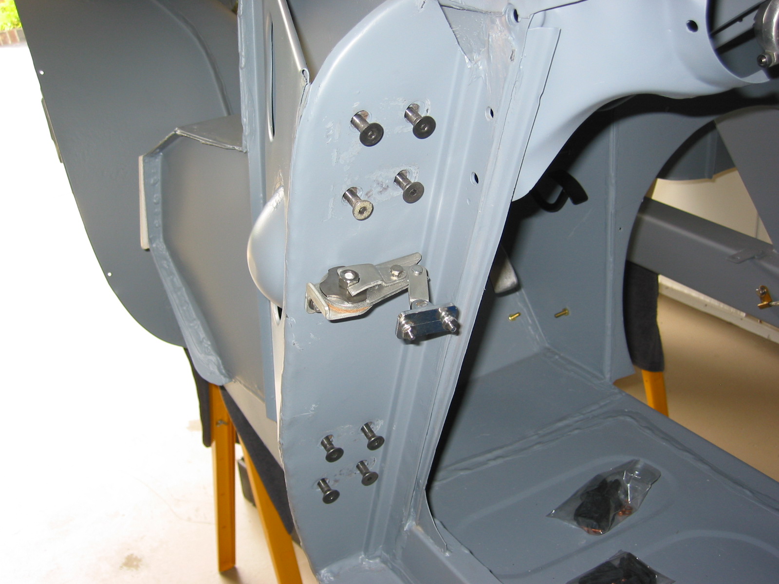
Door Strap 2
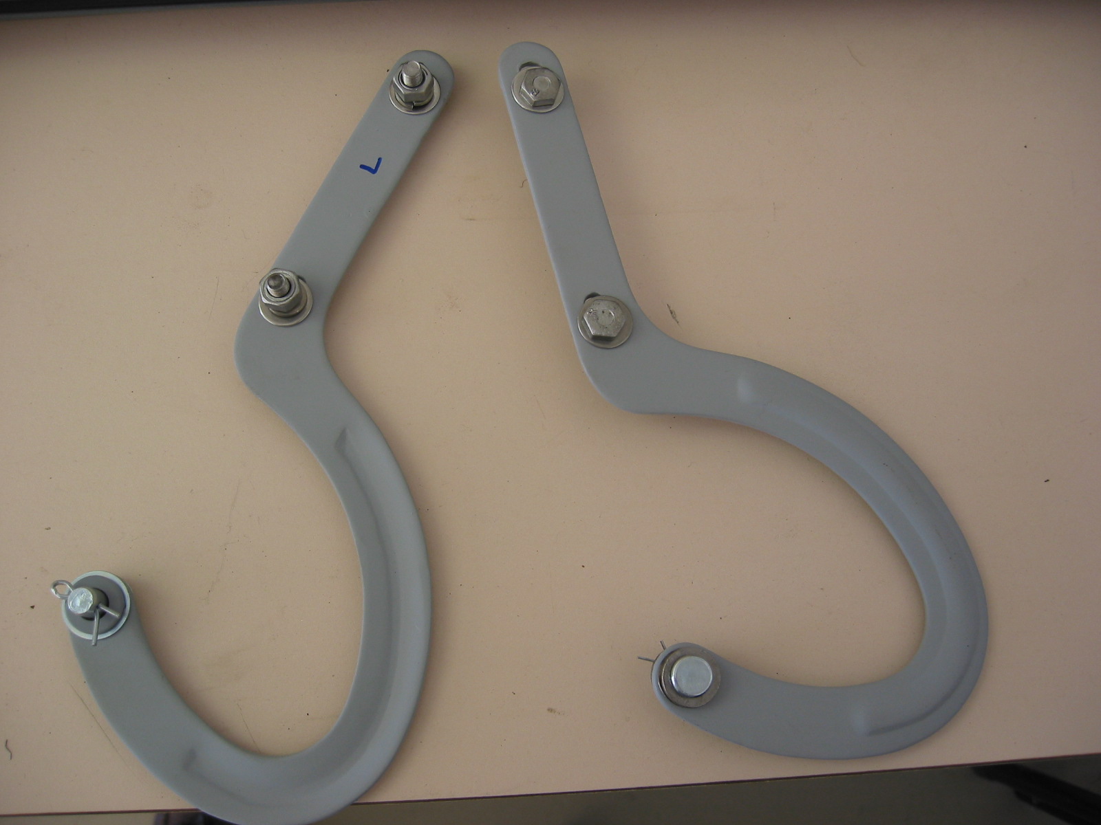
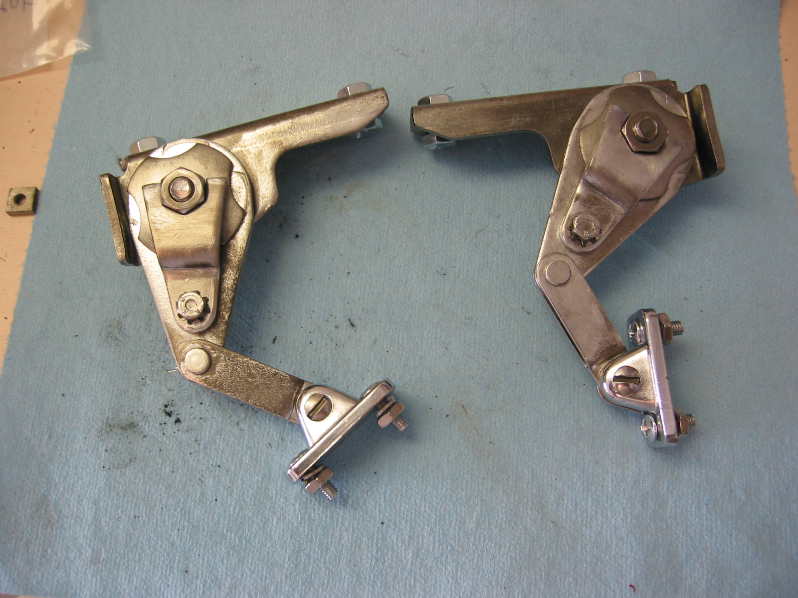
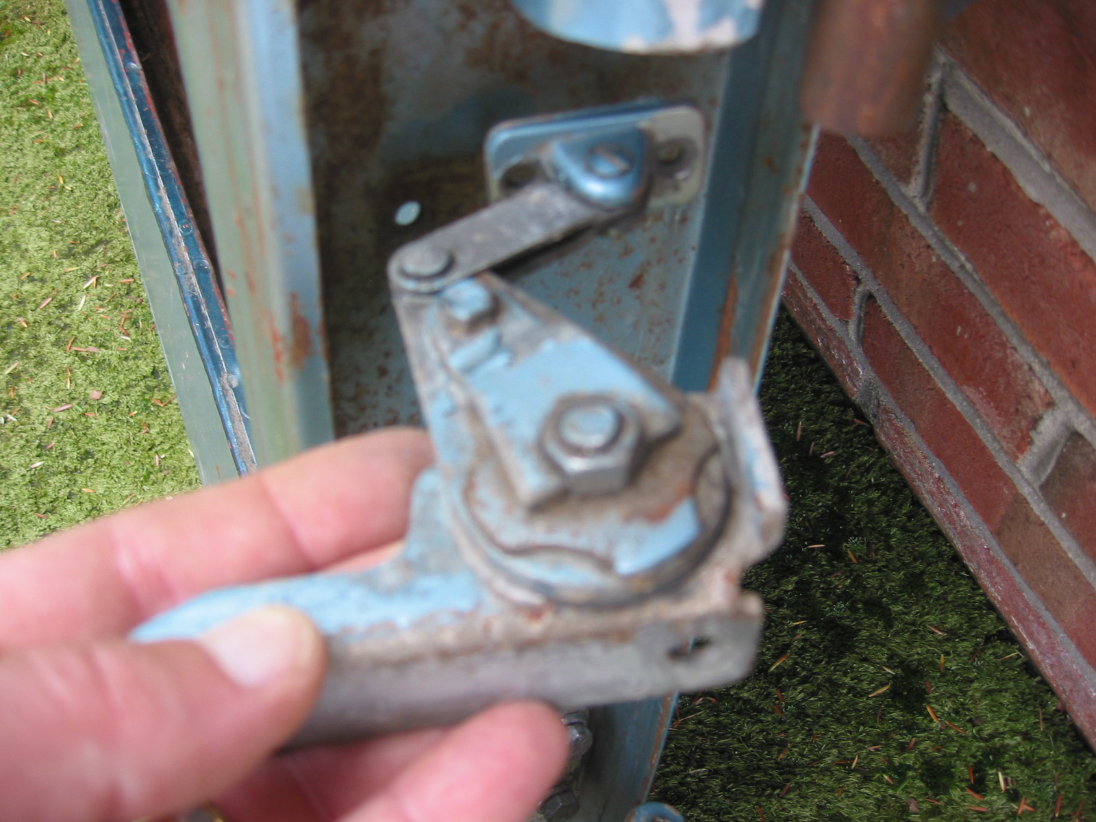
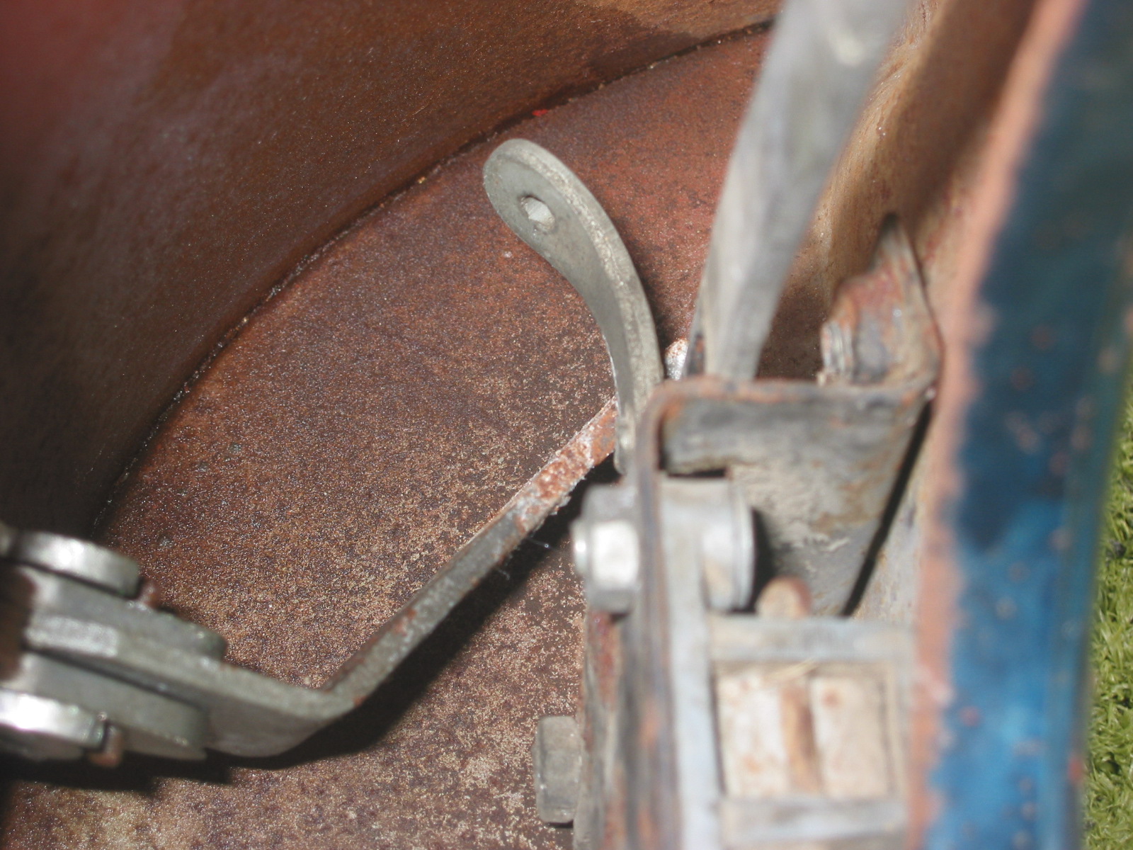
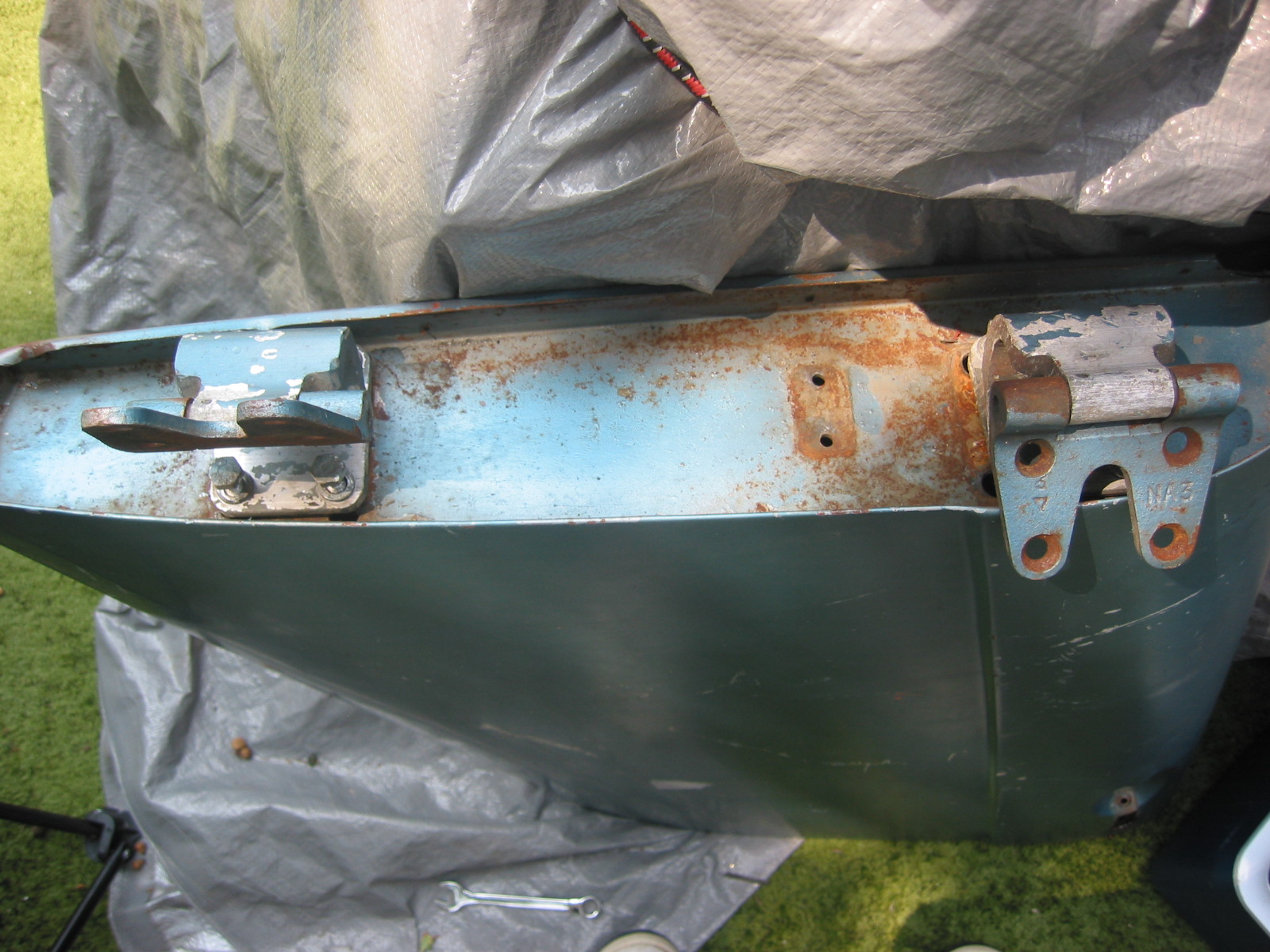
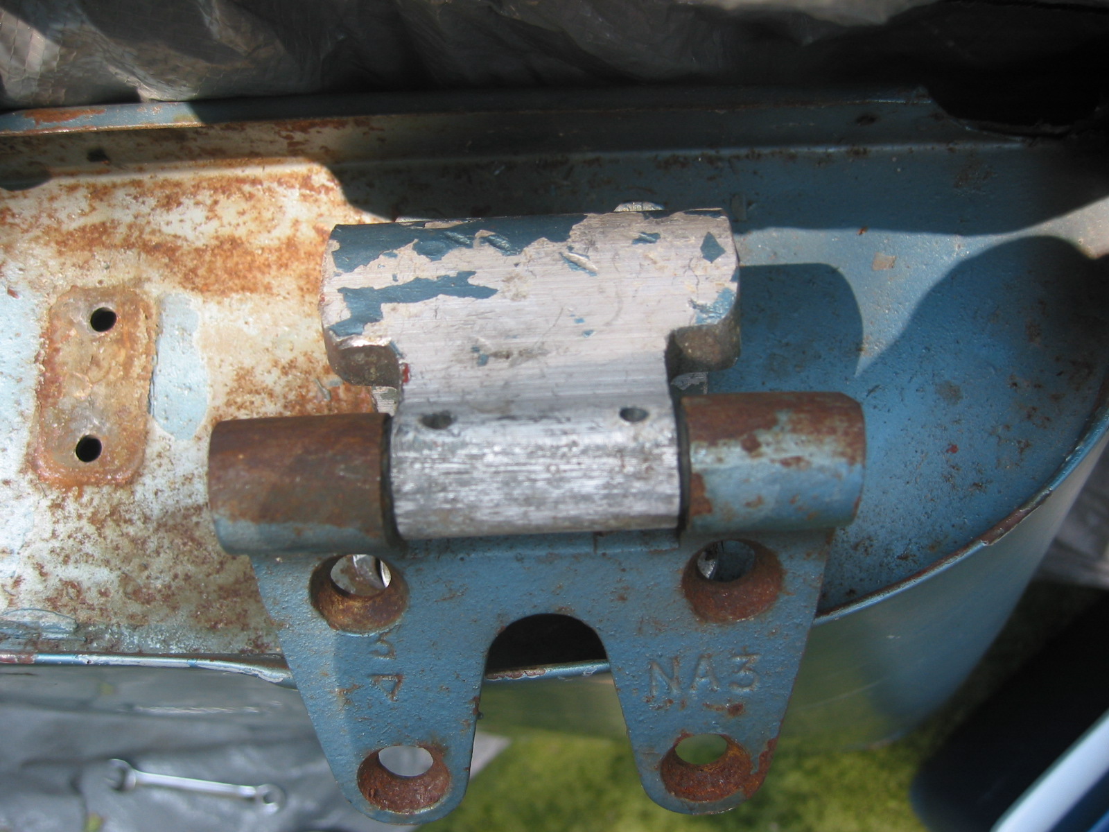
Bonnet Hinges – The bonnet hinges were cleaned, primed and new stainless hardware was installed, and then mounted to the car.
Bonnet Hinge 1
Bonnet Hinge 2
March 22, 2003
More Cleaning
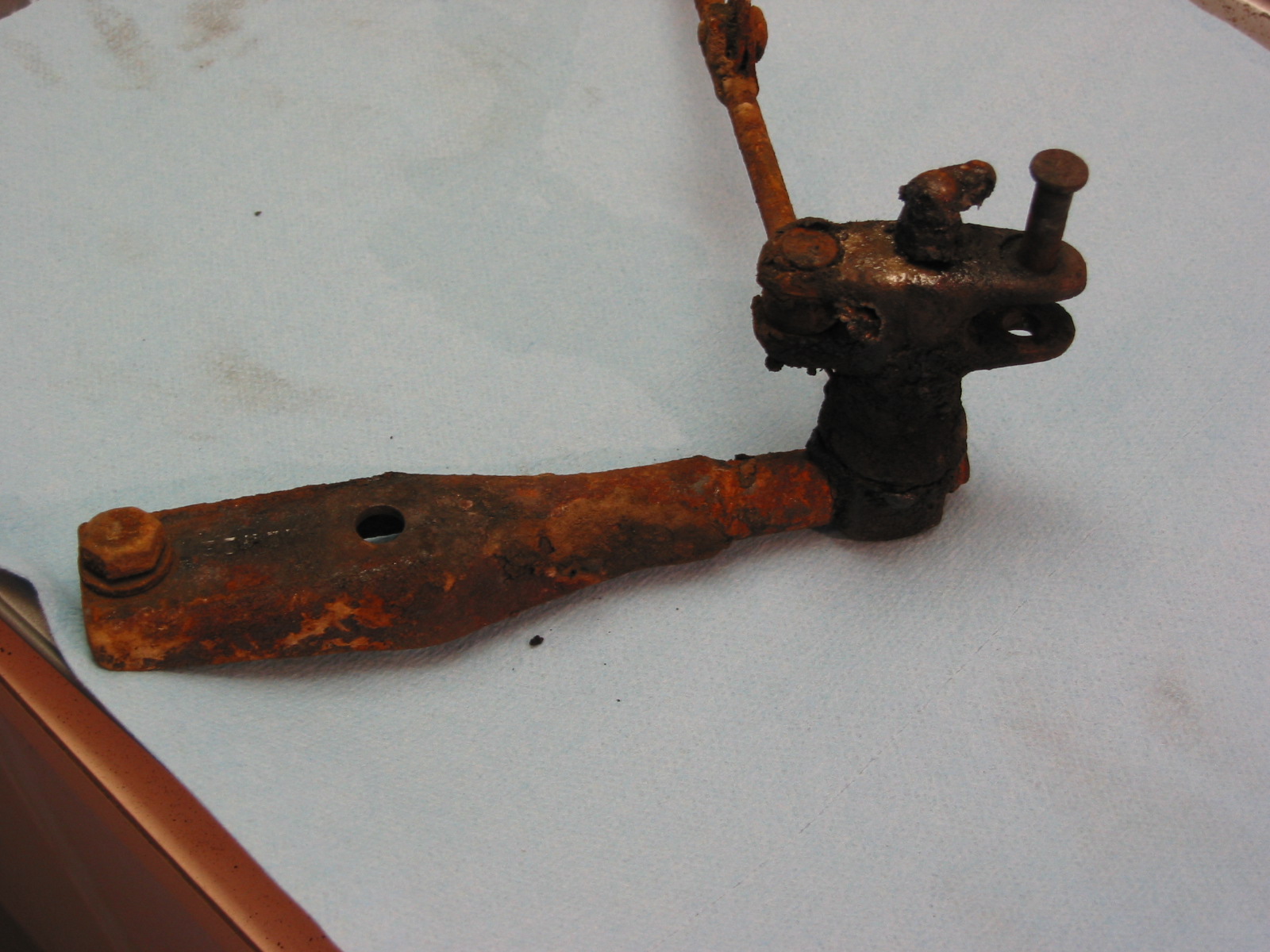
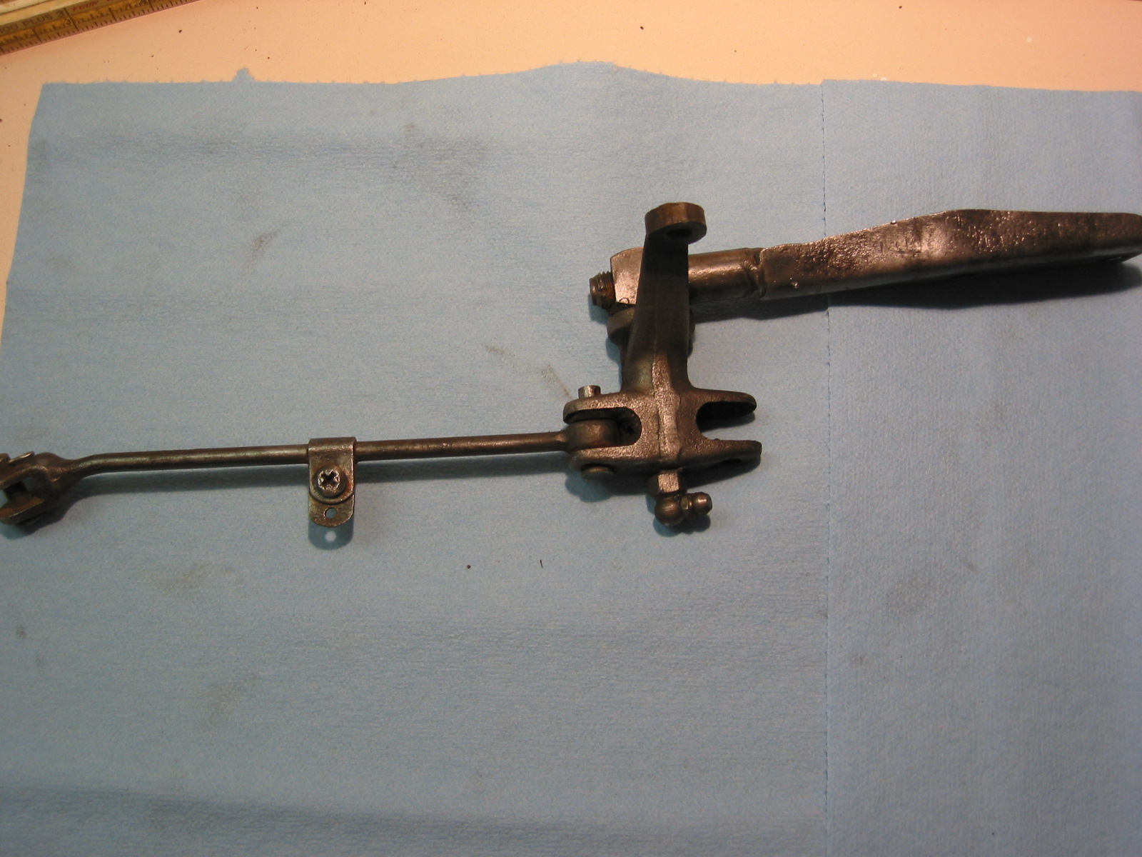
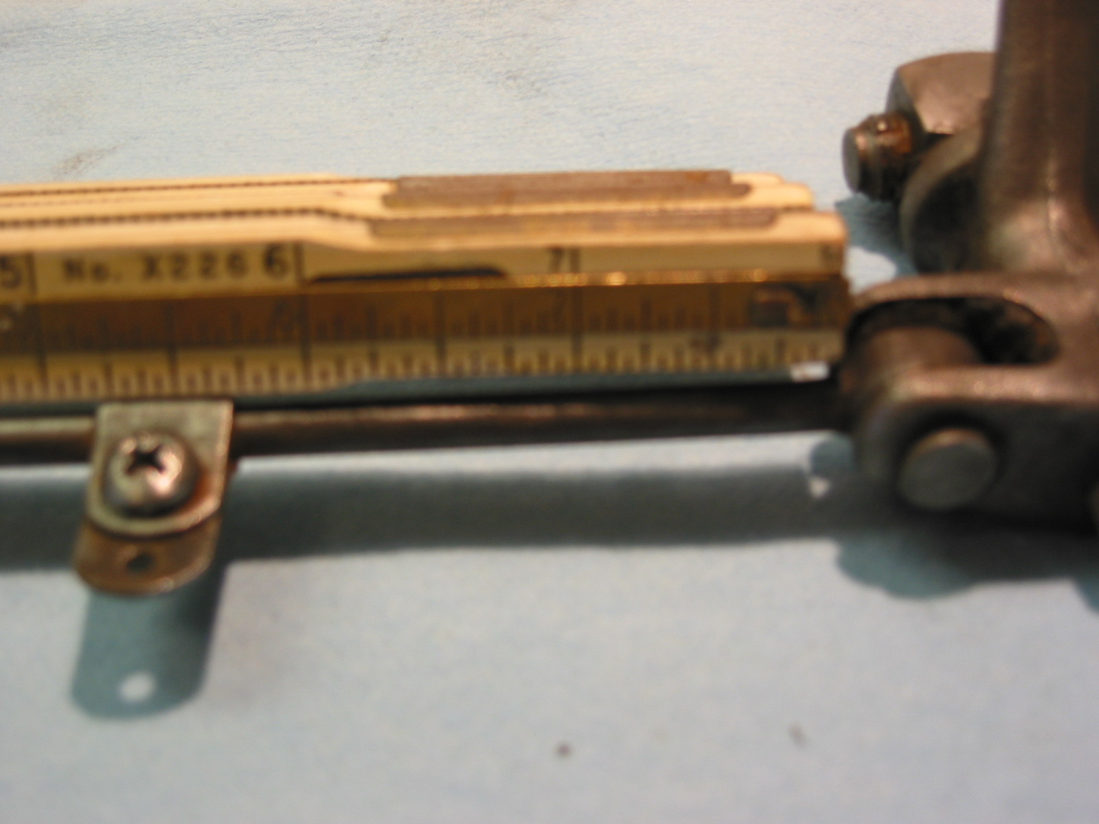
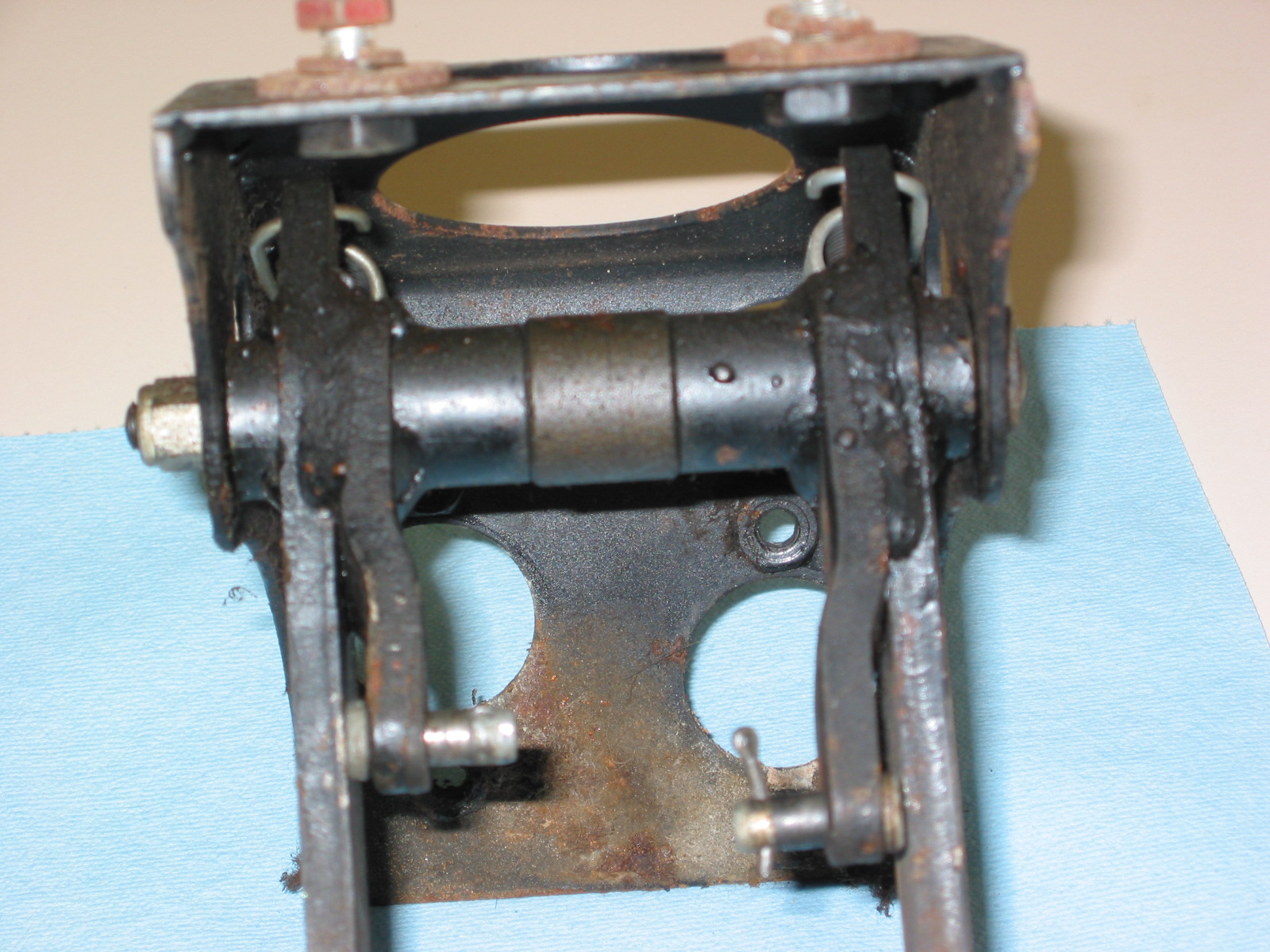
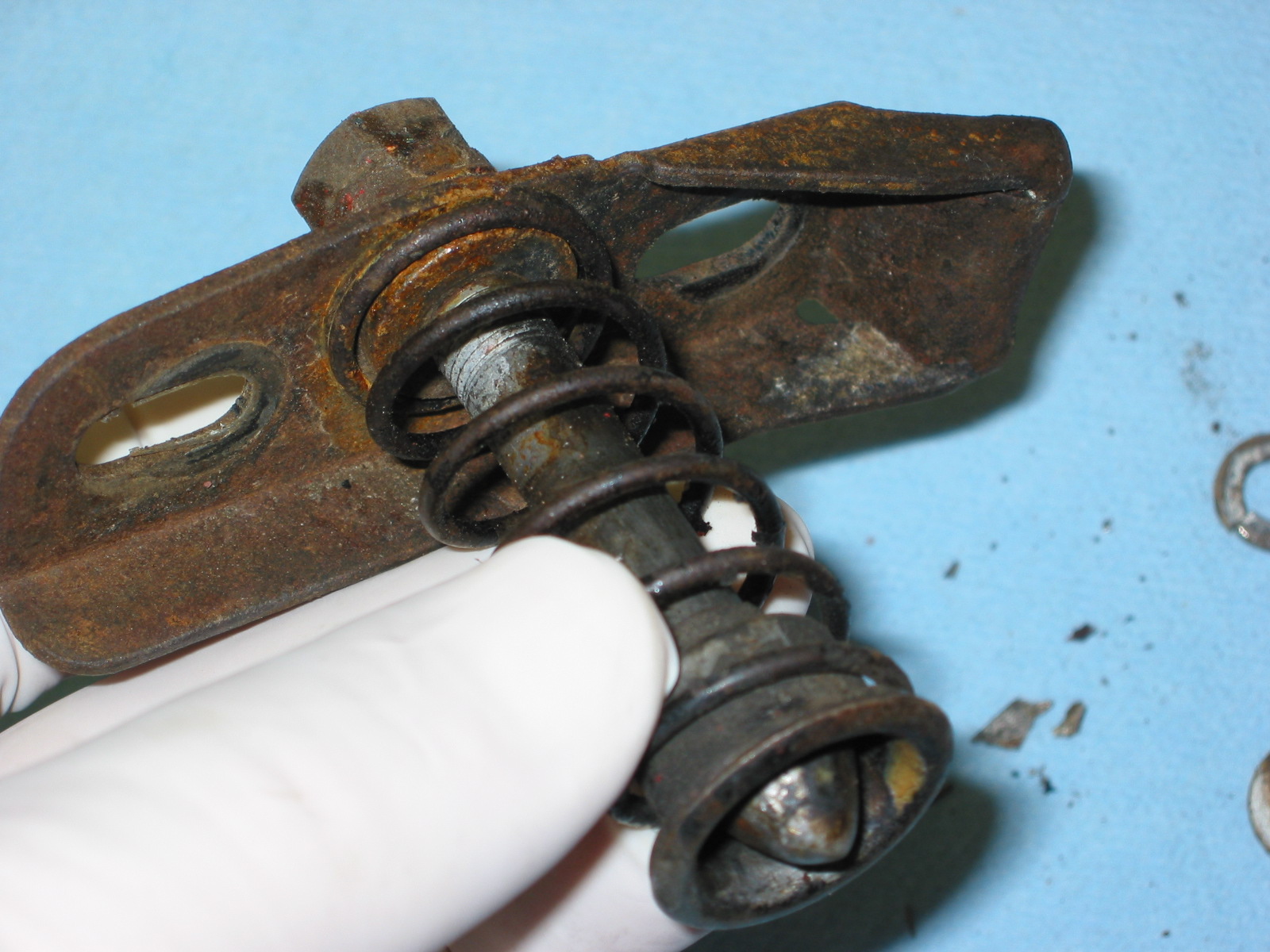
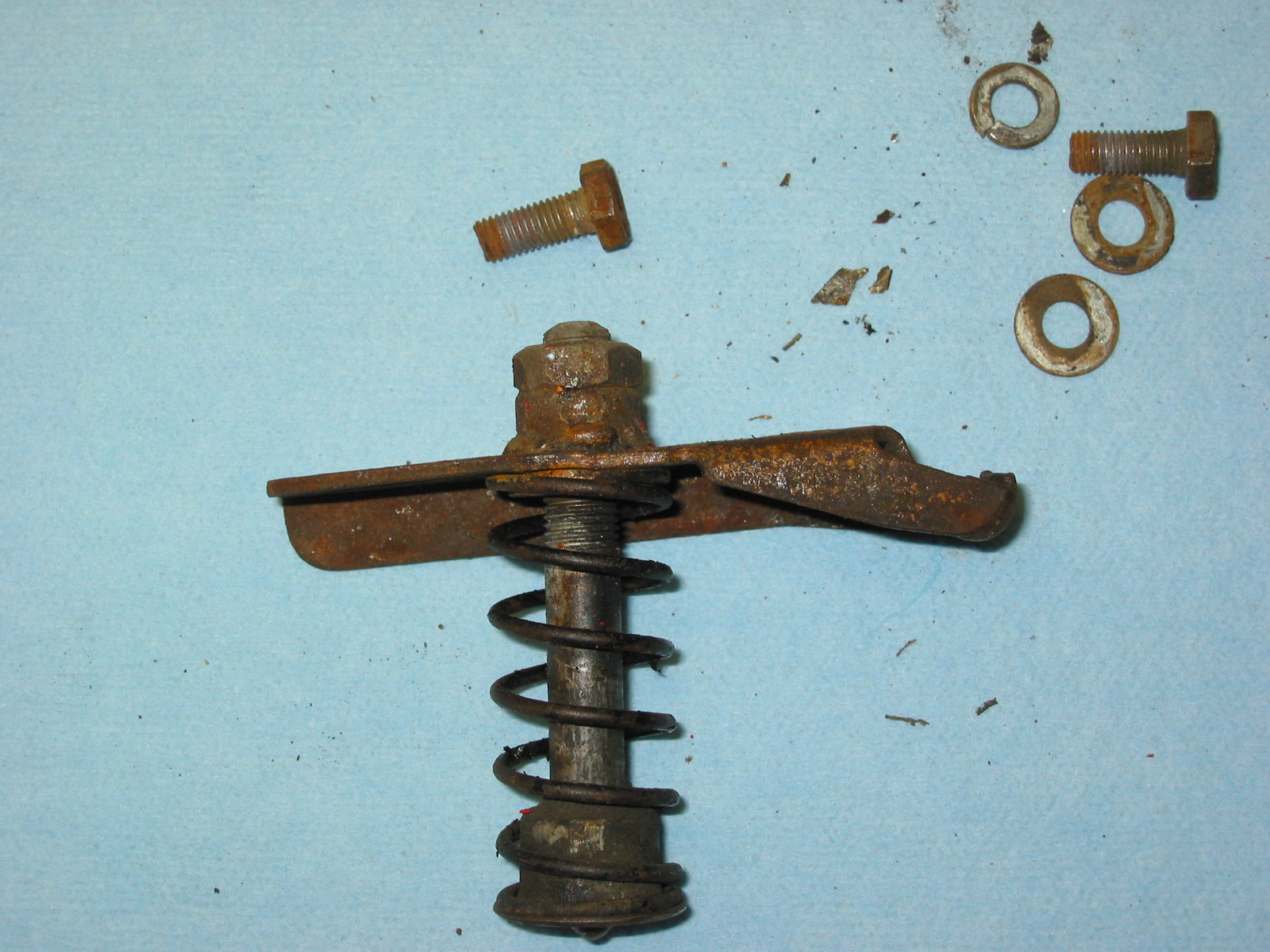
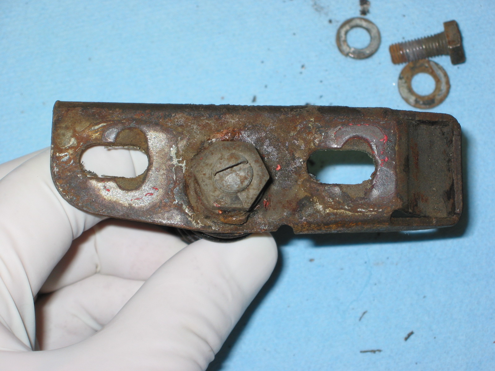
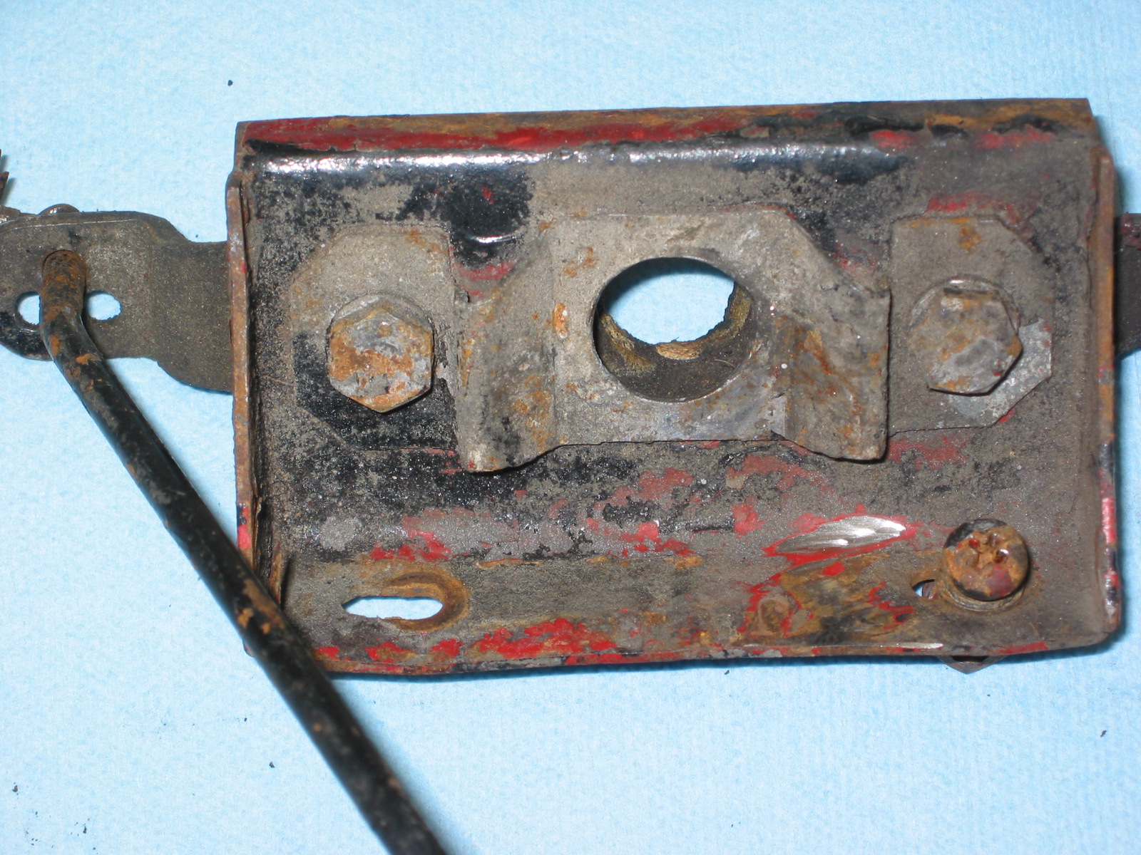
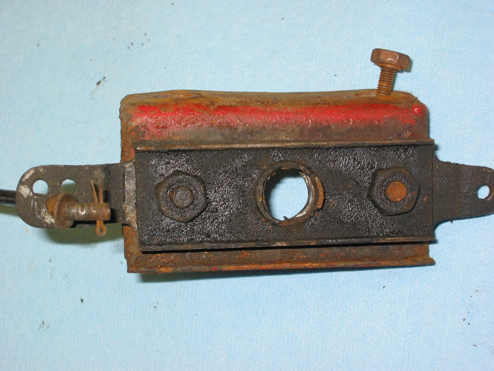
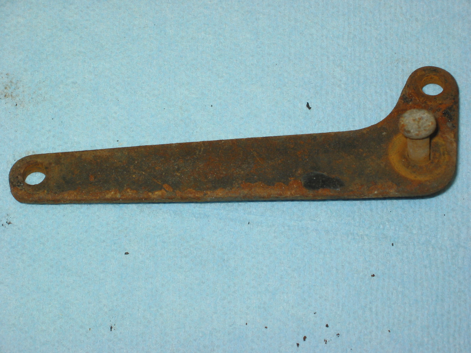
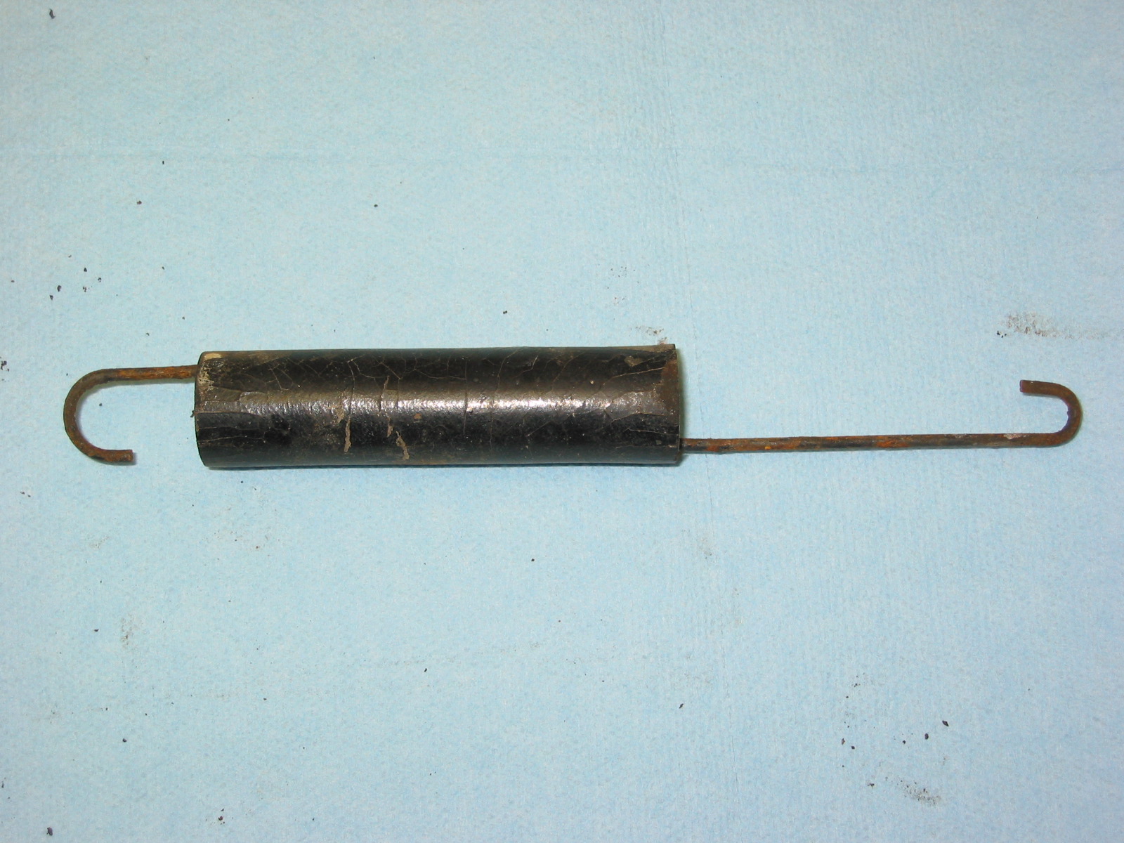
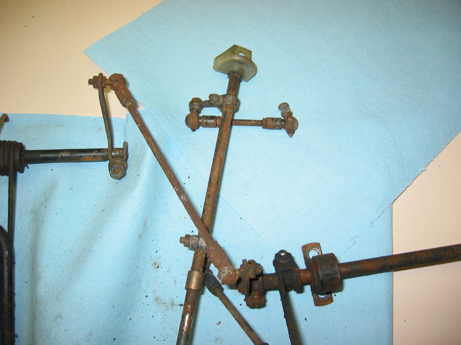
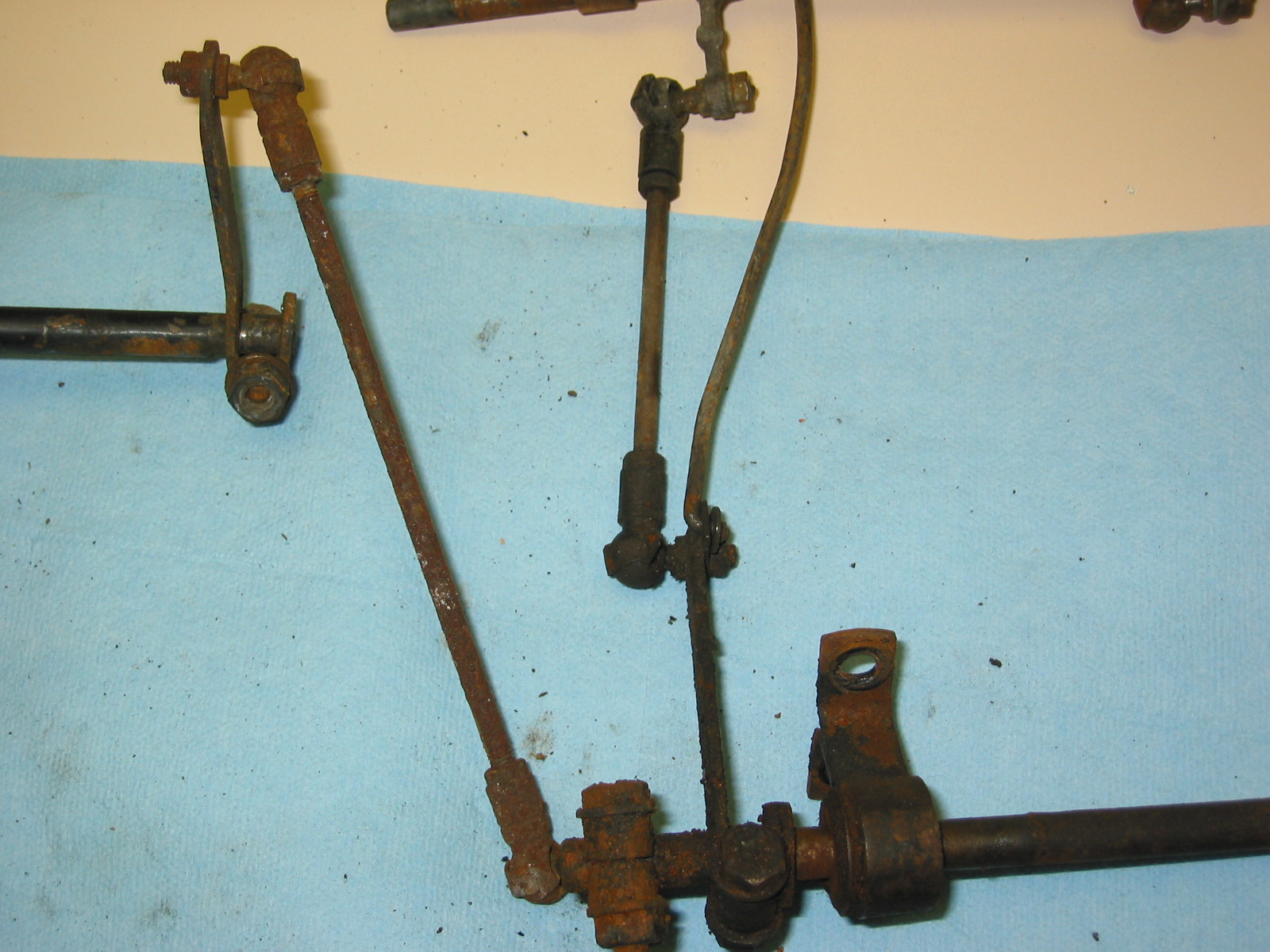
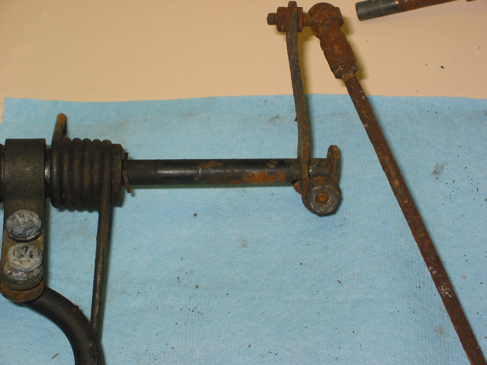
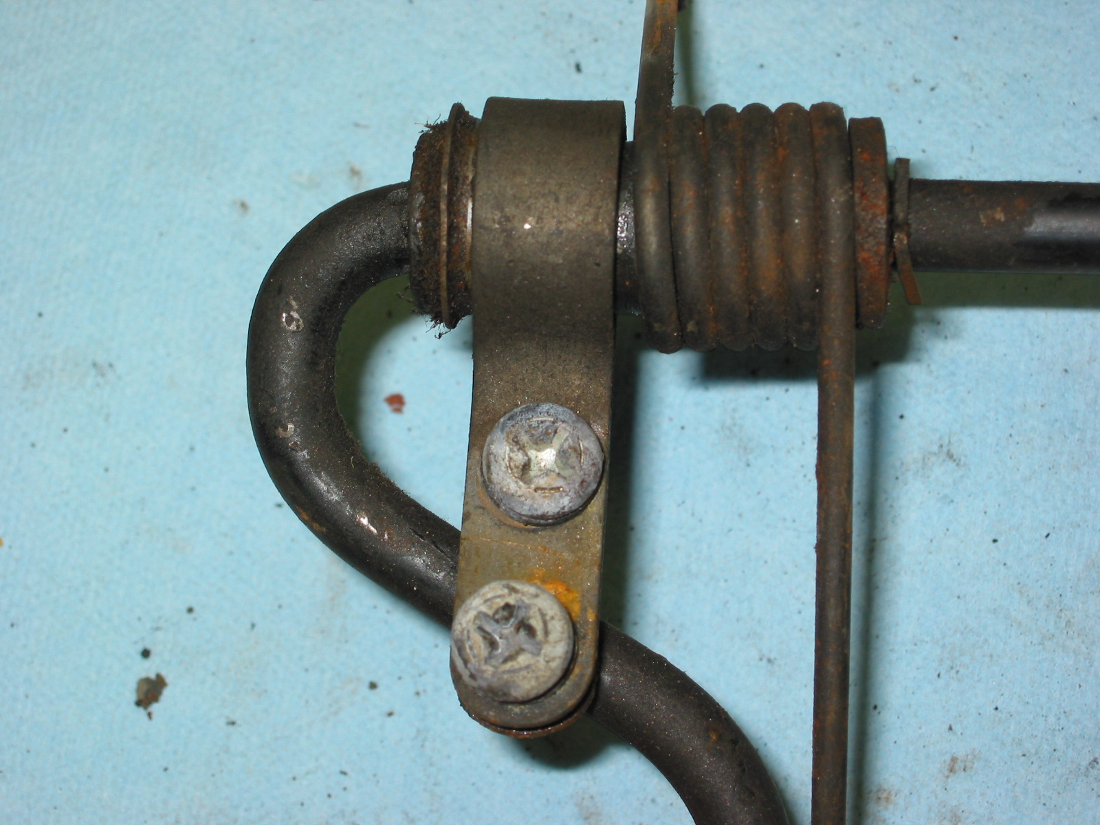
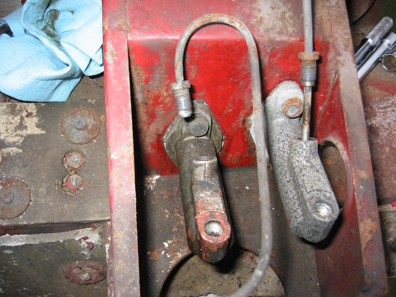
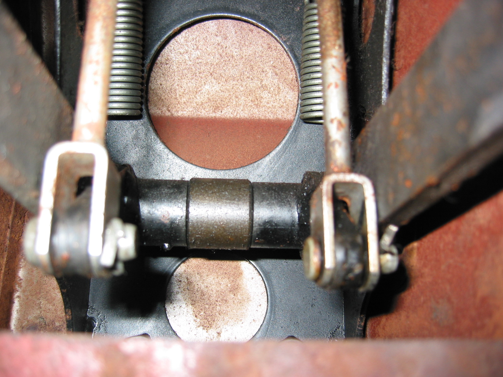
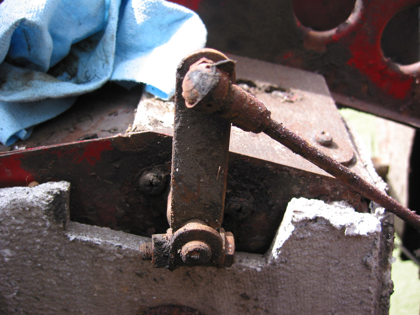
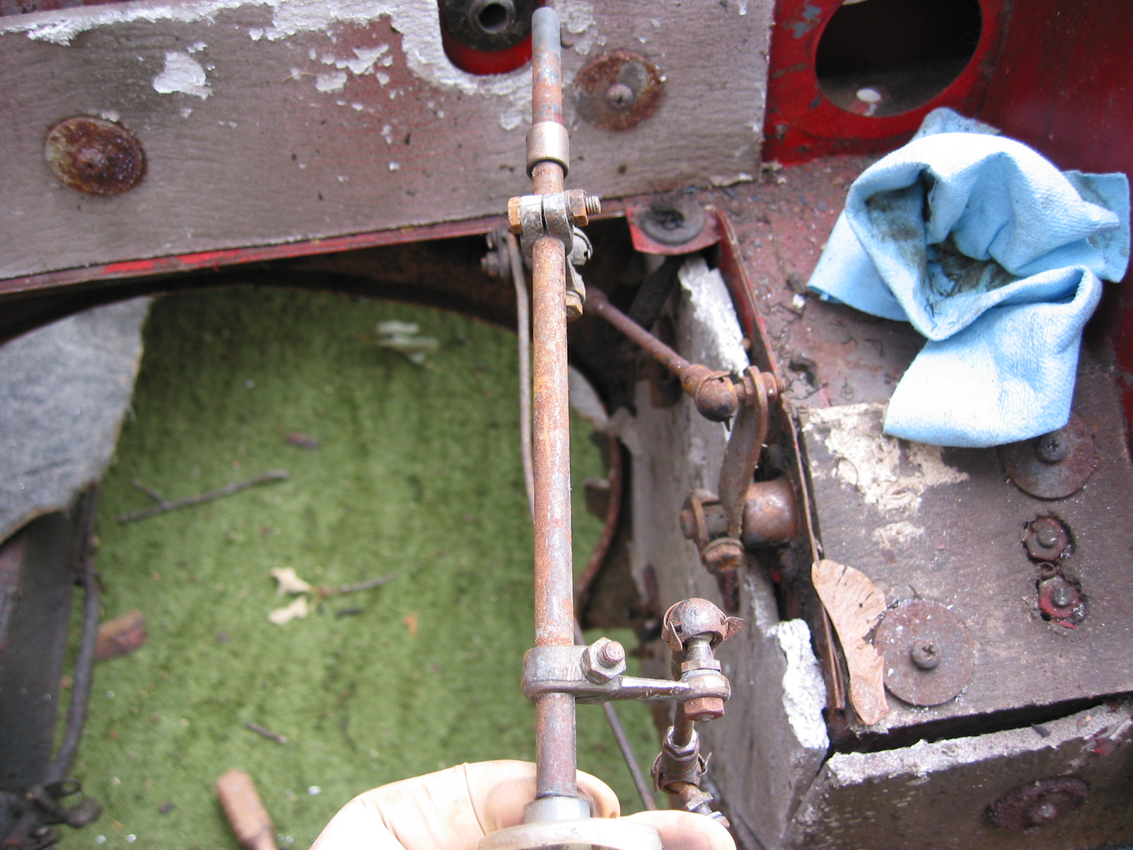
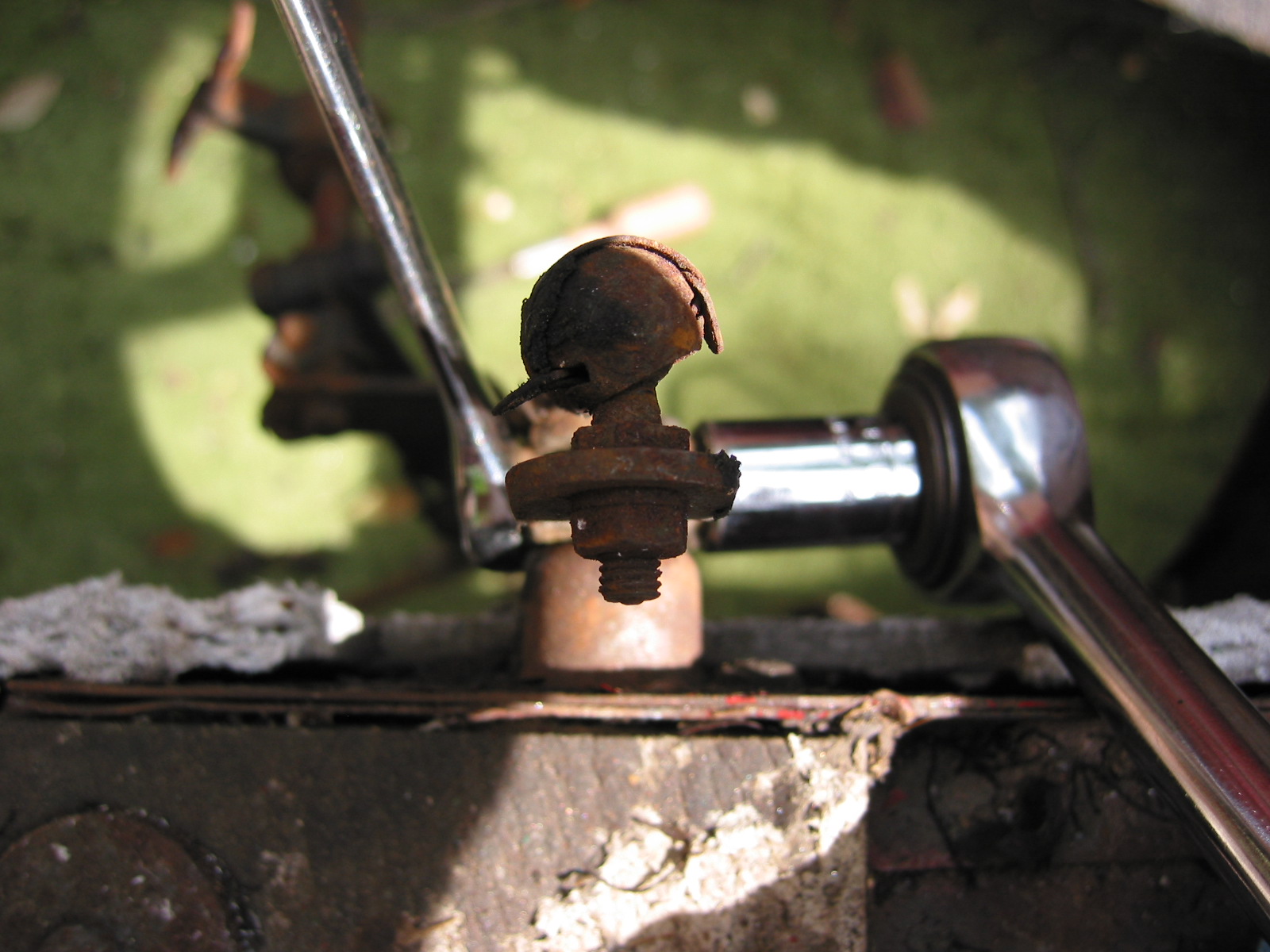
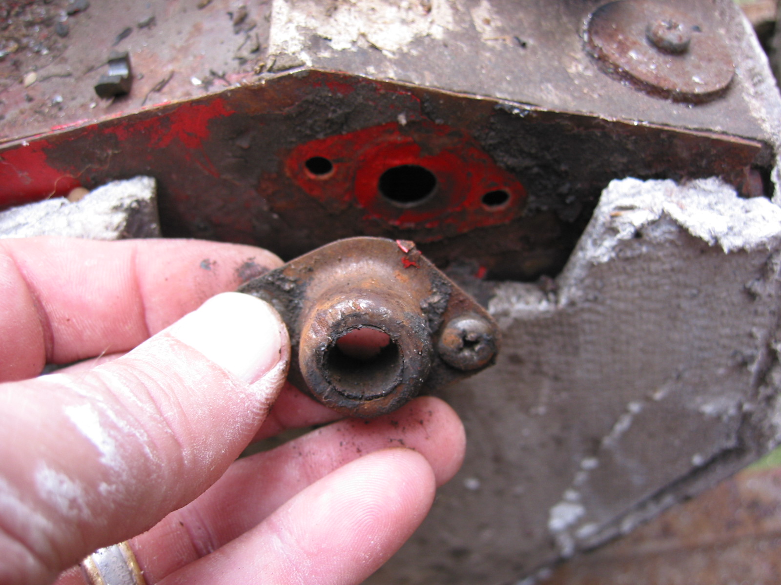
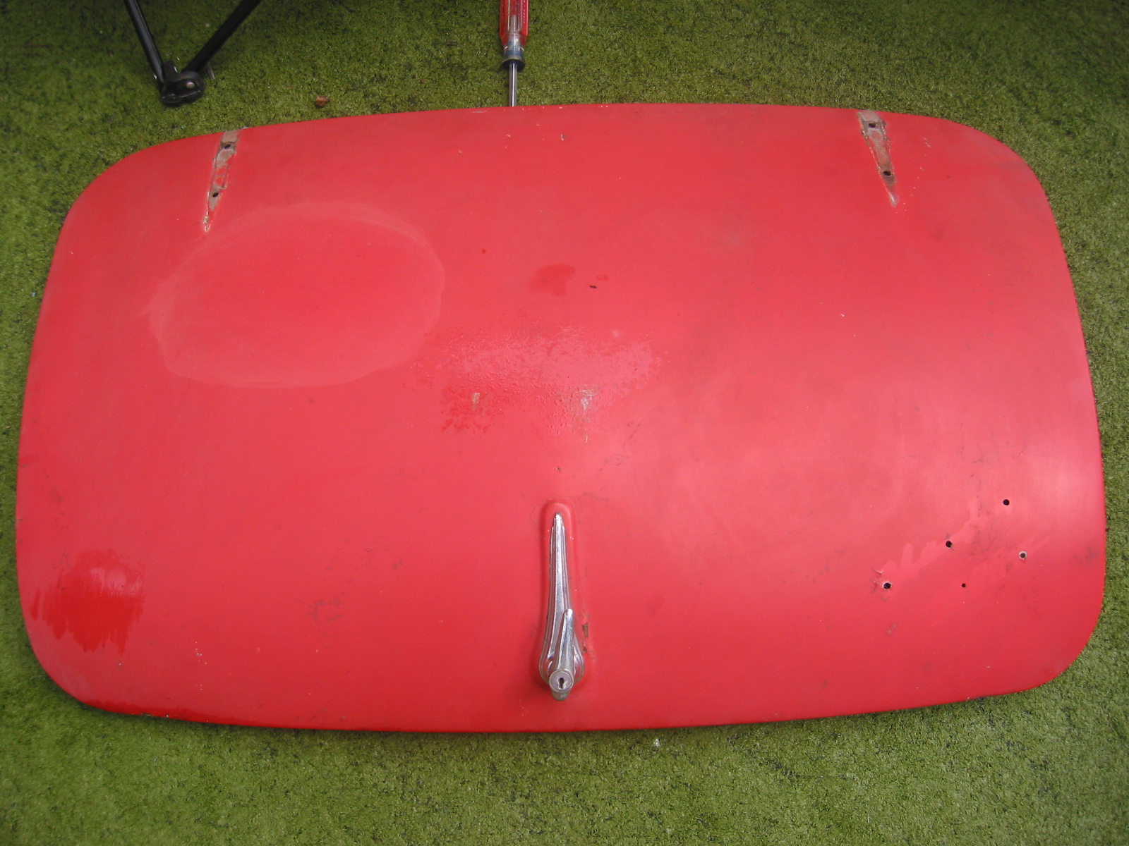
Bonnet Latch Hardware – Disassembled and cleaned the bonnet latch assembly and the bonnet opening rod assembly for Jeremy Turner to media blast and paint.
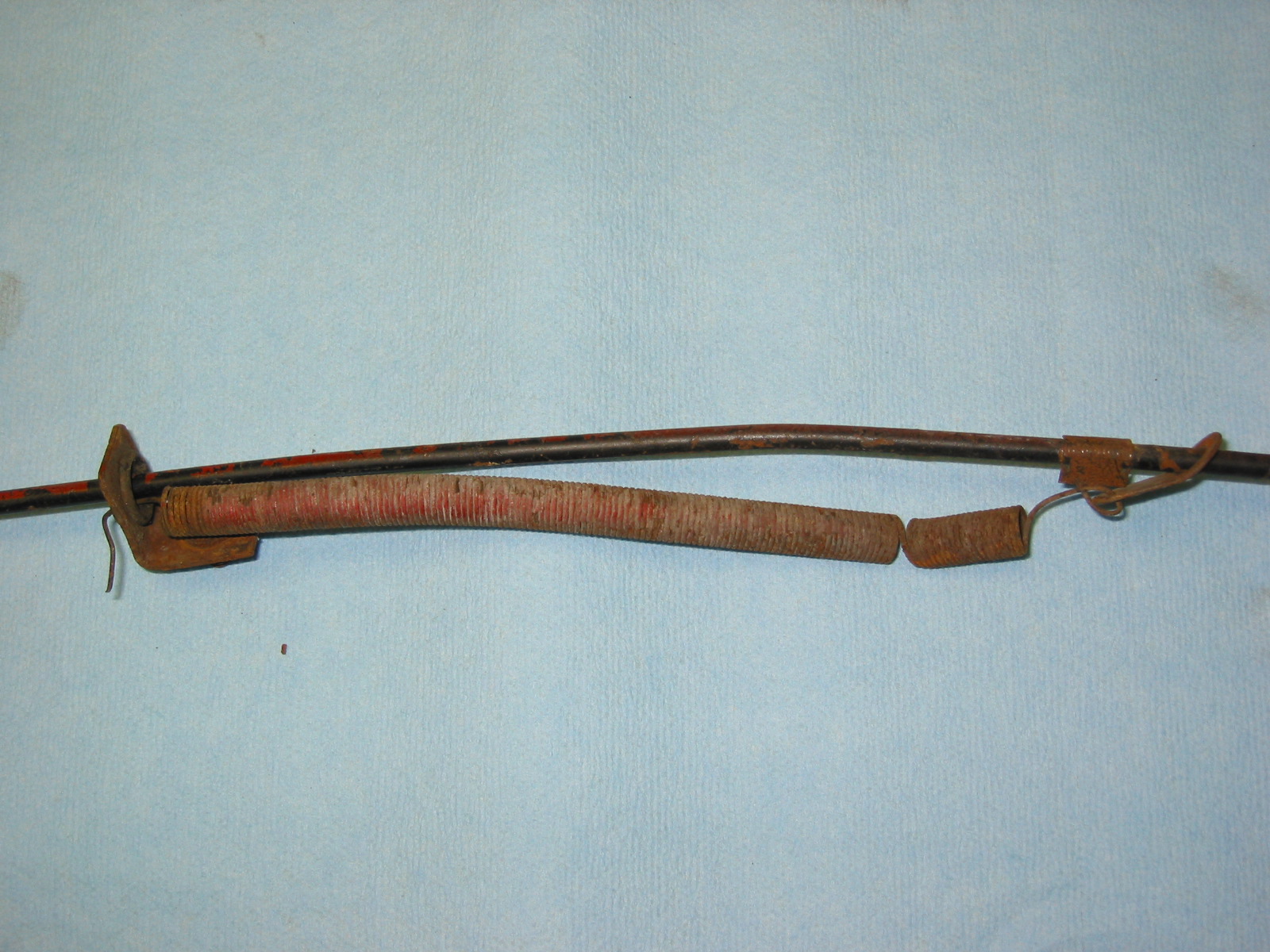
Bonnet Rod Spring
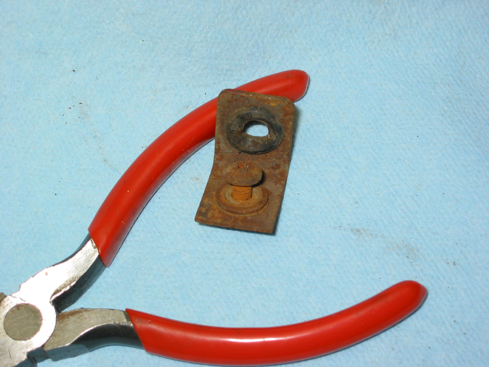
Bonnet Rod Bracket grommet
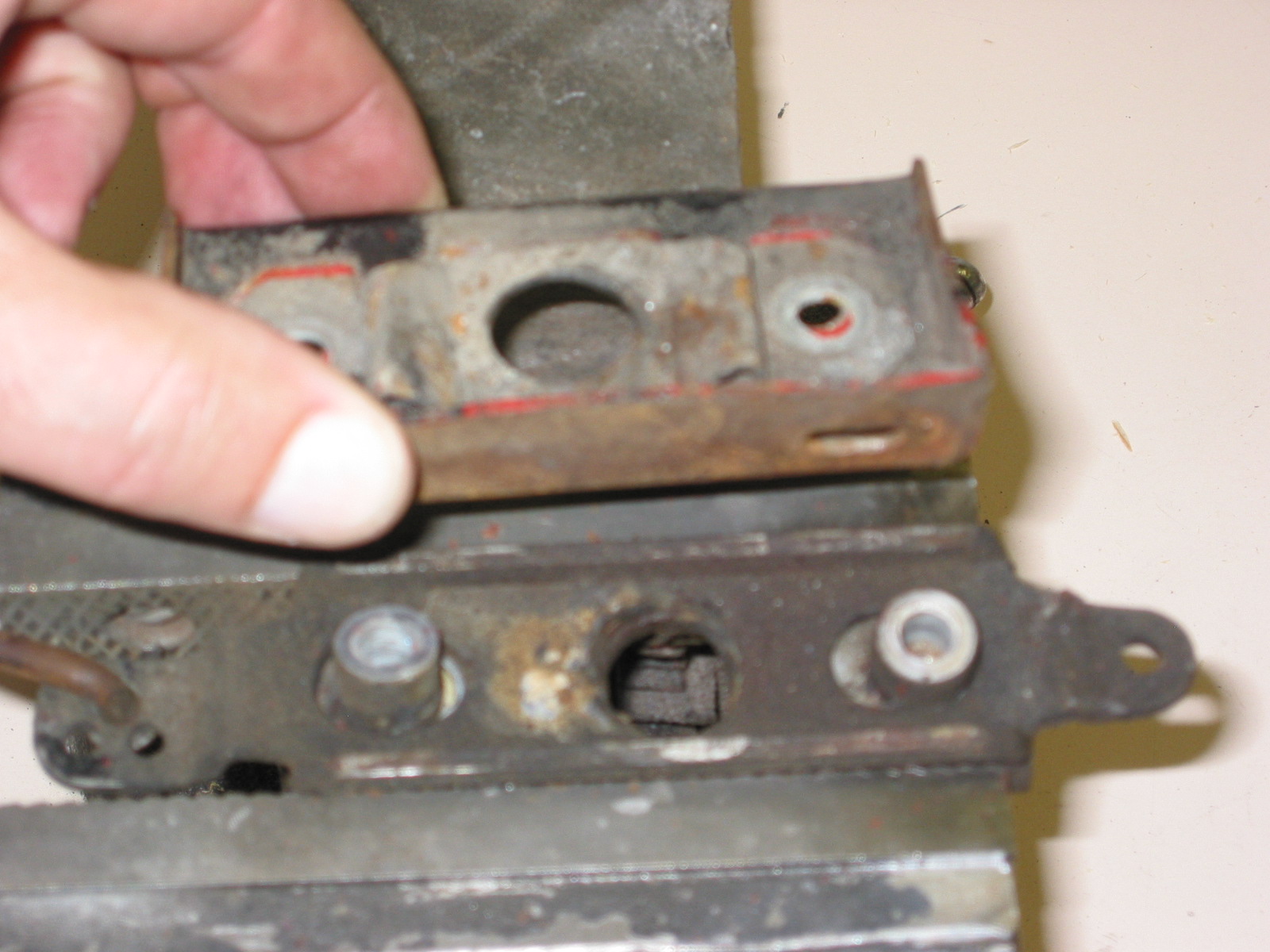
Bonnet Latch A
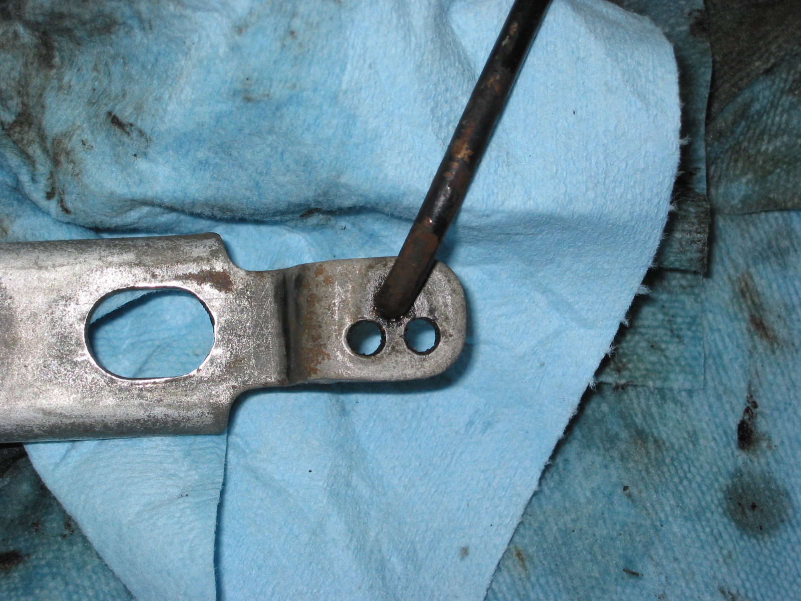
Bonnet Latch B
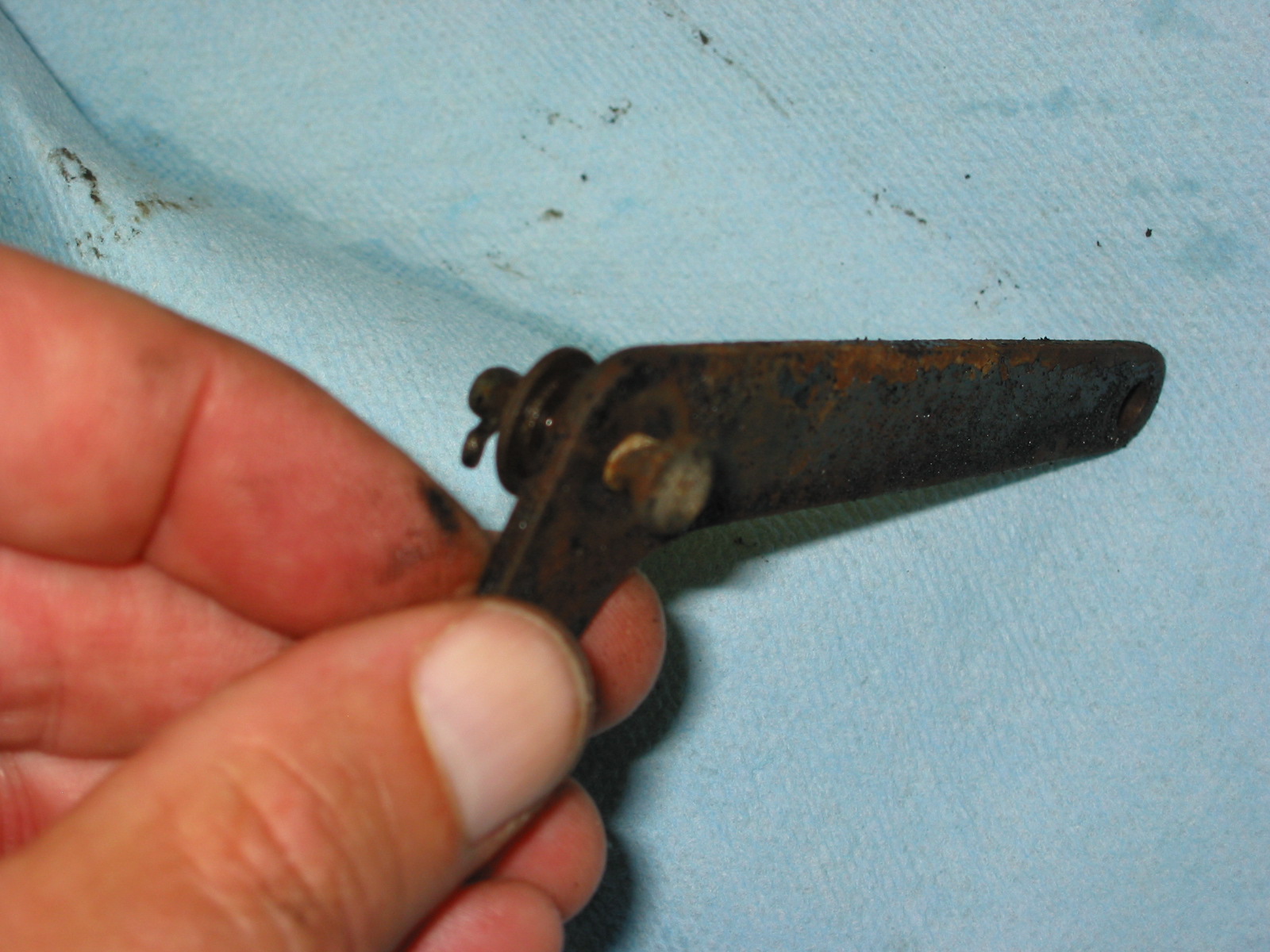
Bonnet Latch C
Also cleaned the bonnet rod clip, the catch bracket, two safety latches, the brake reservoir bracket and two shroud brackets.