Center Console Arm Rest

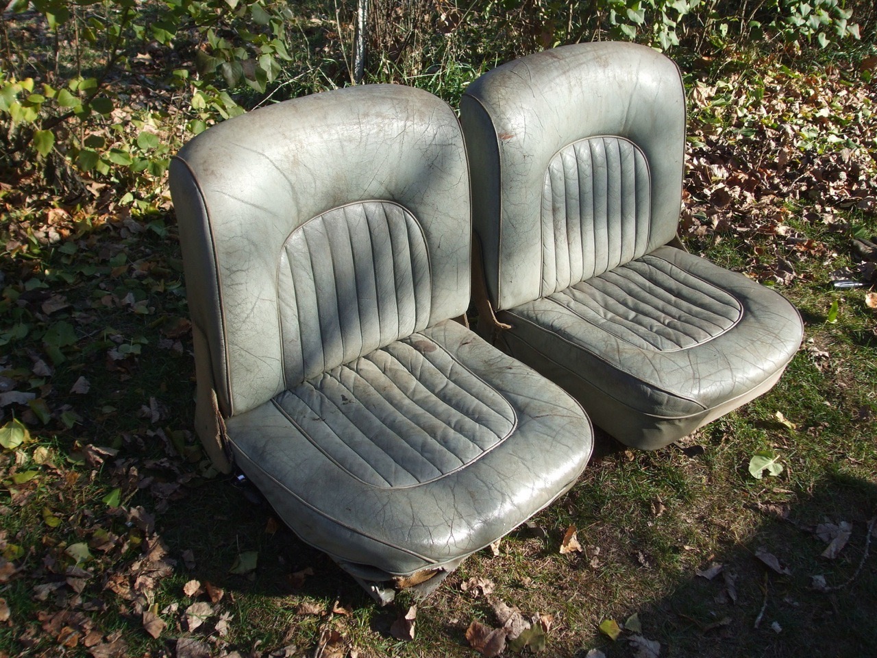
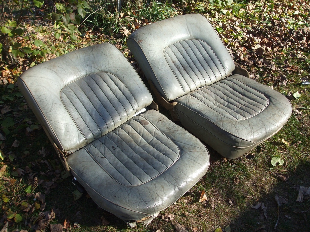
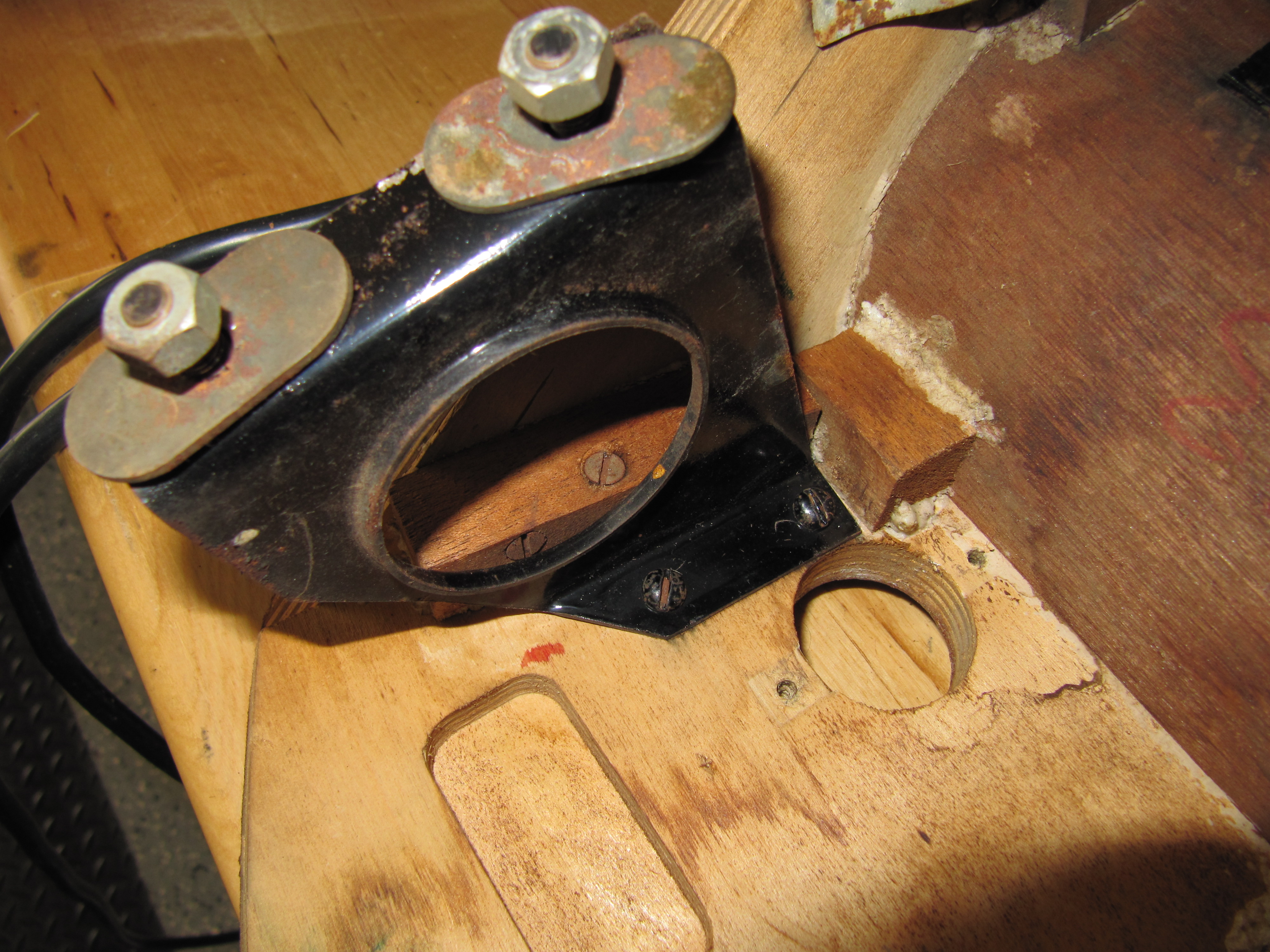
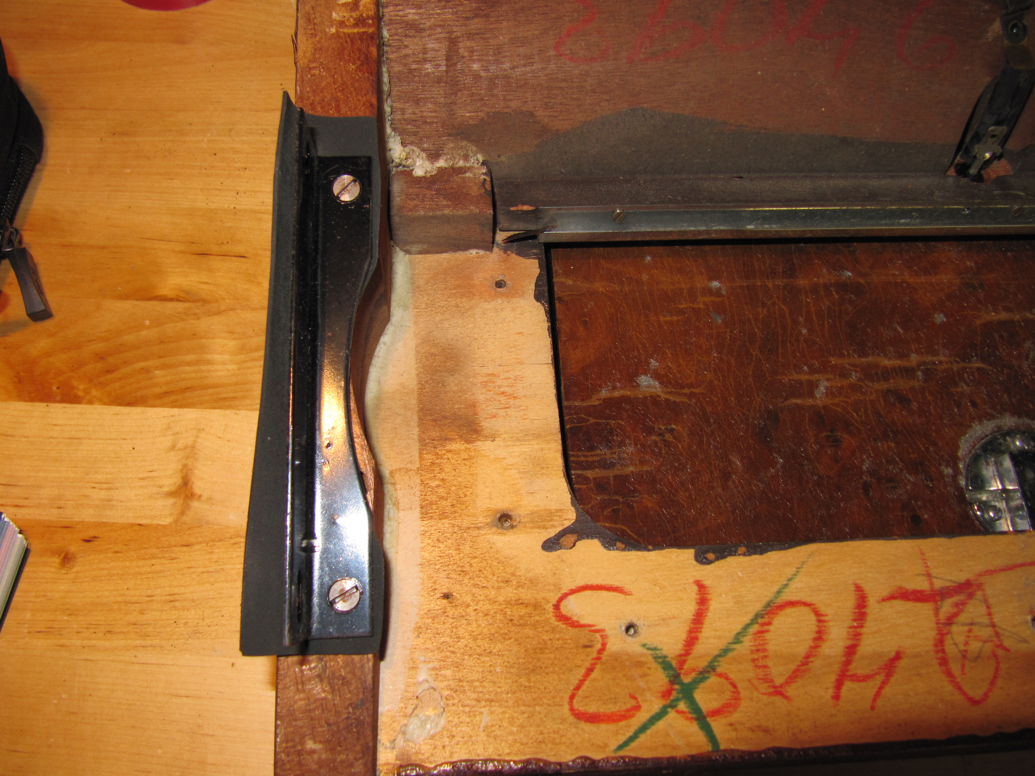
Inspired by Kevin Moore’s MK2 center console arm rest modification, I endeavored to create my own. I knew that I wanted to use an arm rest pad that would not look home-made, and that would also house the controls for the power seats and a USB dual port. These are images of Kevin’s console/arm rest:

Kevin Moore’s Console/Arm Rest

Kevin Moore’s Console/Arm Rest

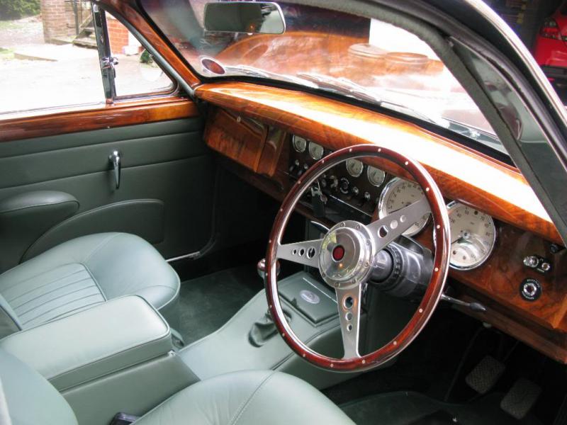
I think that Kevin’s execution is spot on and well done. I can only hope that mine turns out as well!

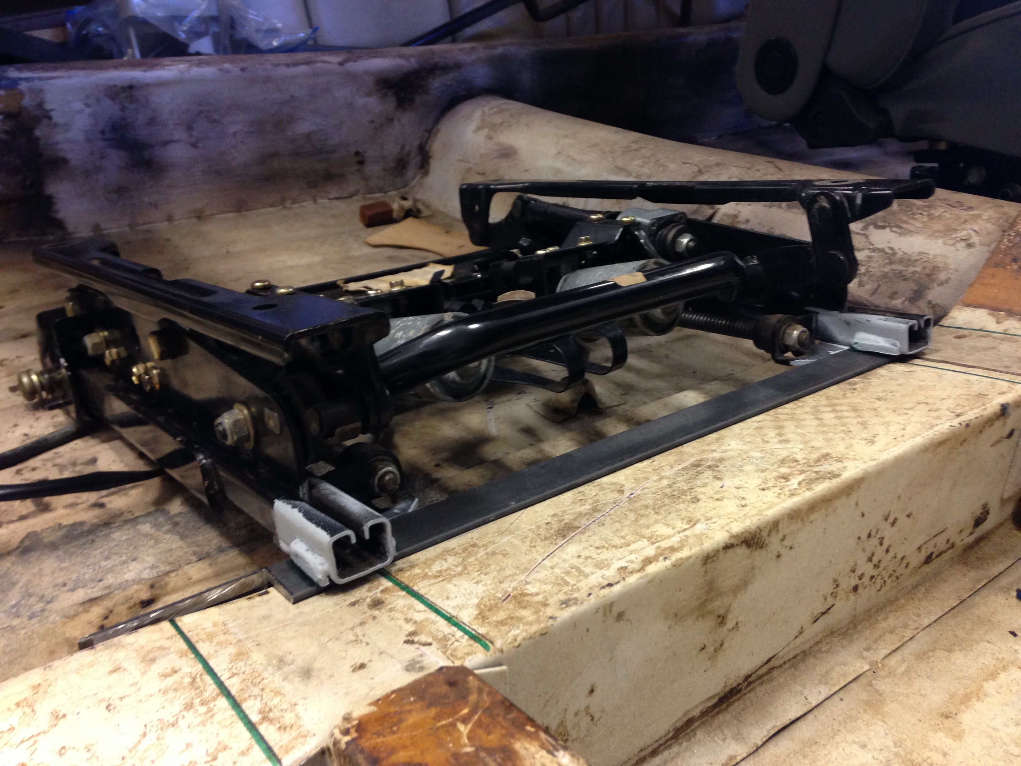
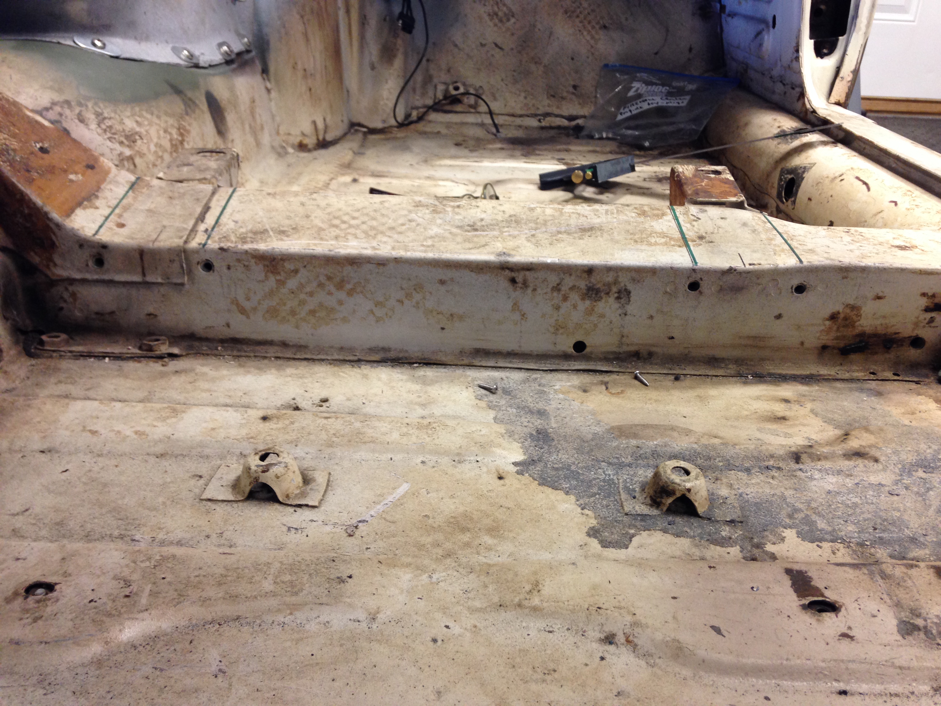
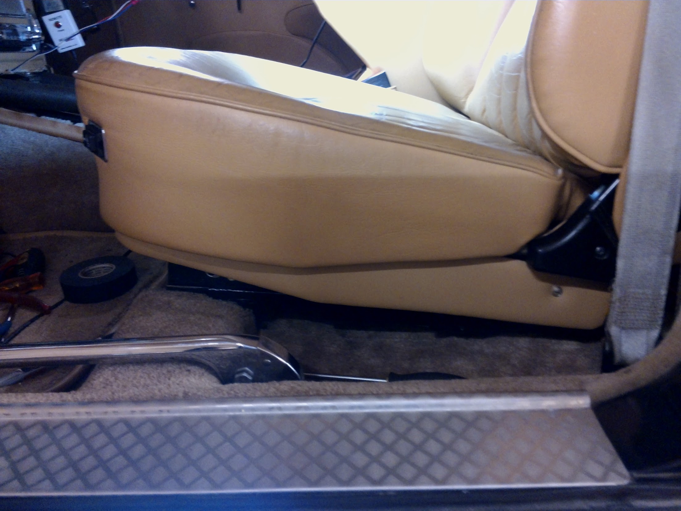
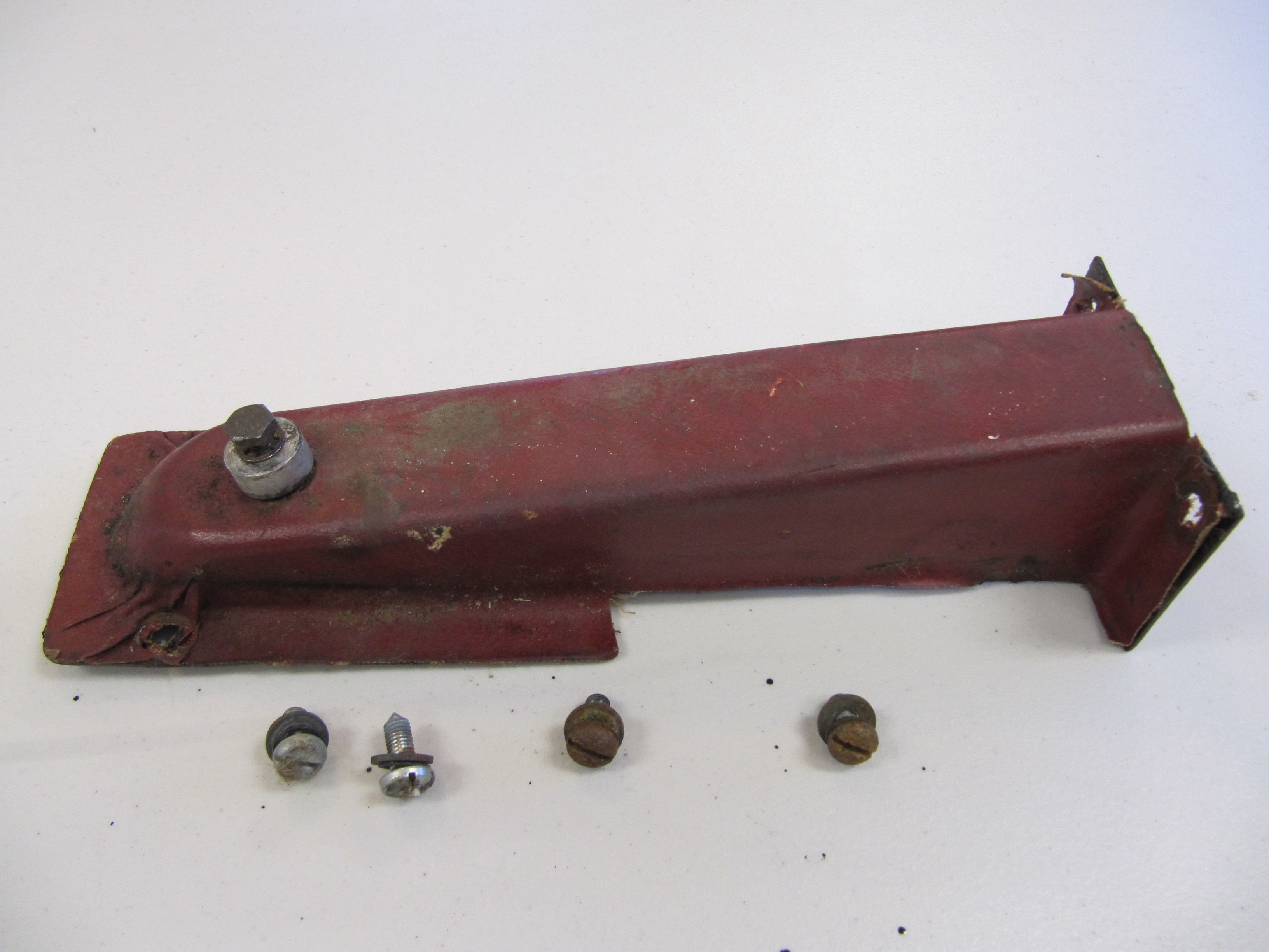
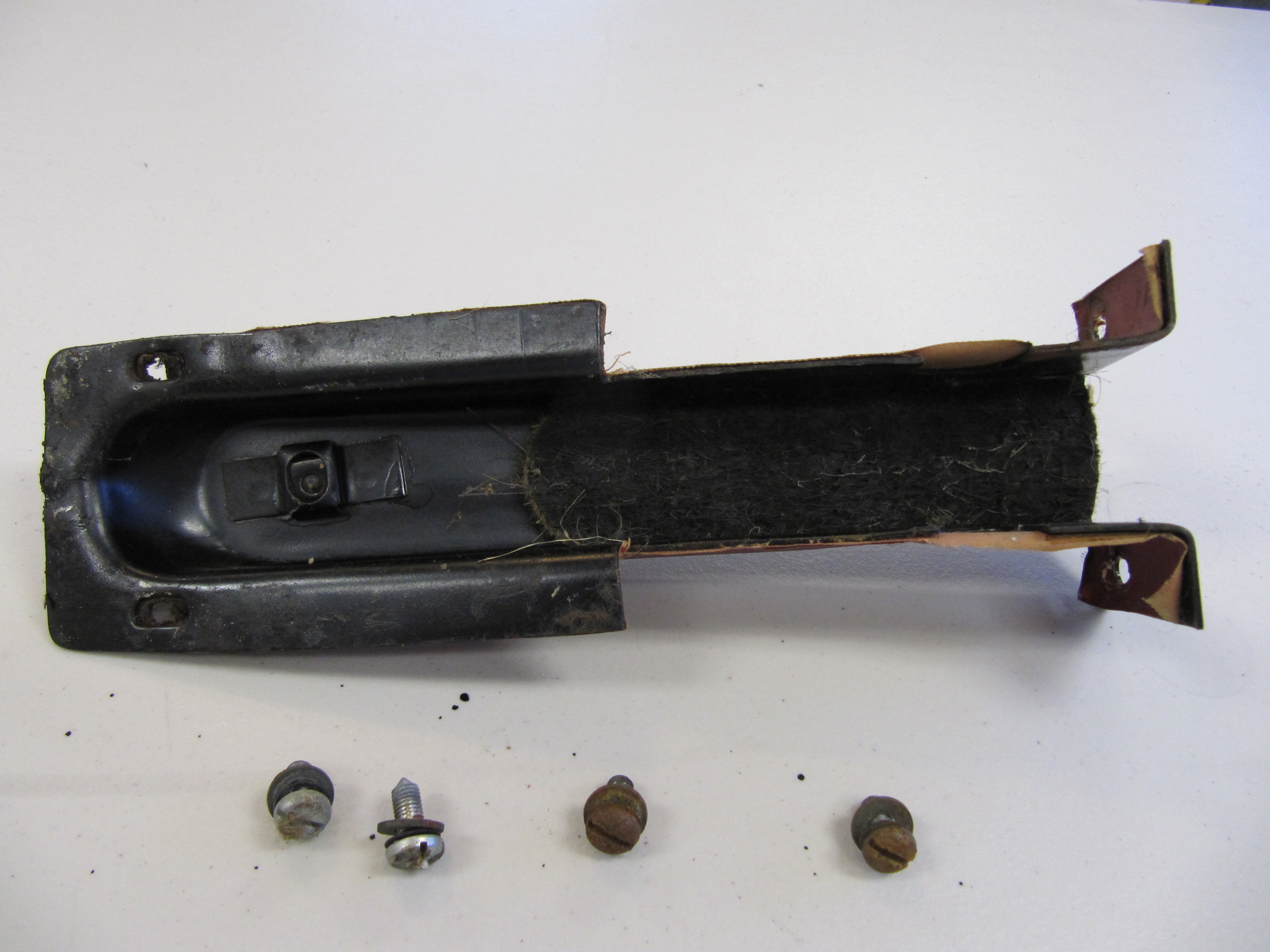
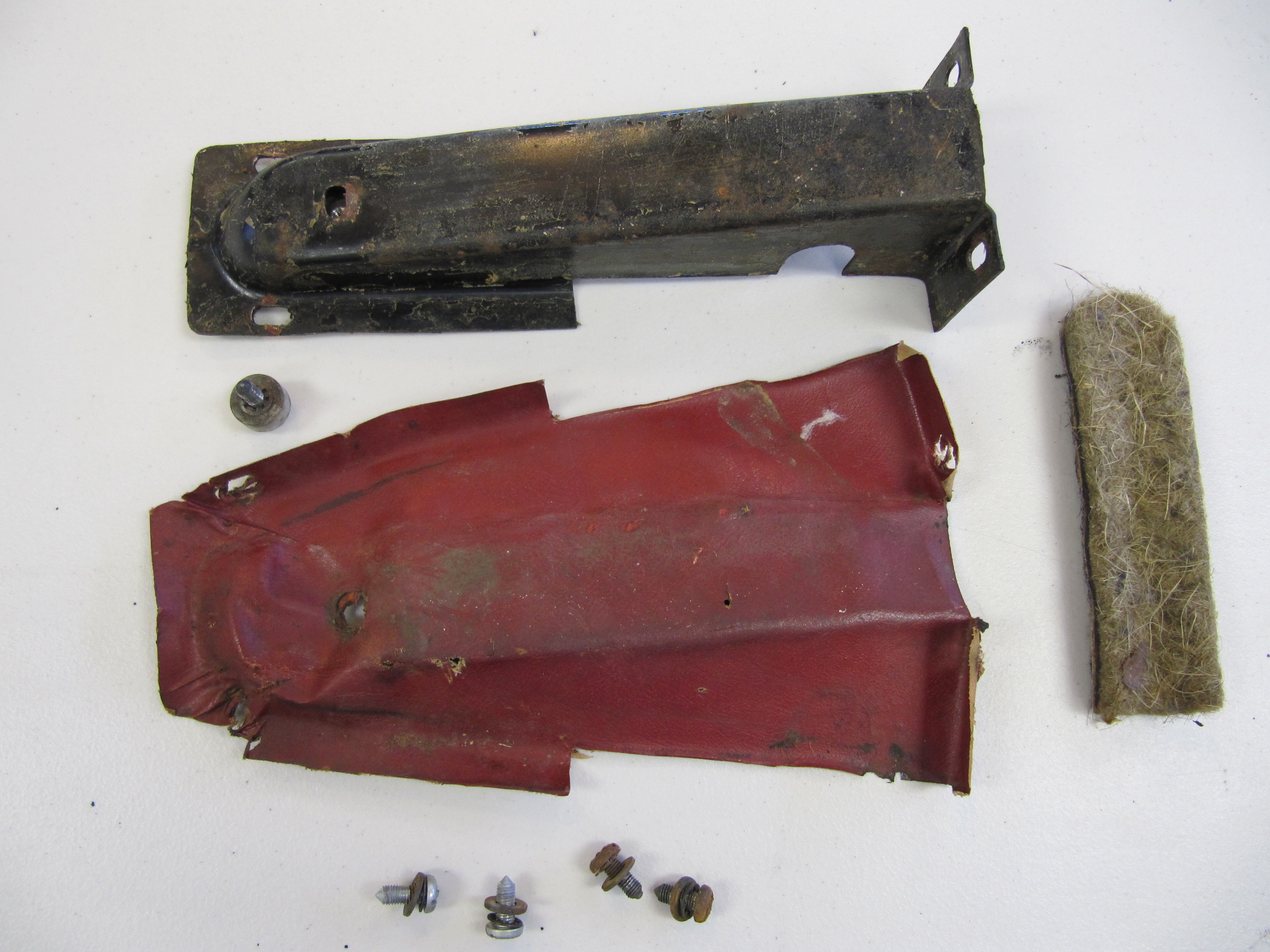
My project began with an arm rest pad/lid and storage tray that I purchased on eBay. I believe they were from a mid-eighties XJ6. The size and shape of the arm rest determined the ultimate measurements of the box I would build. The XJ40 electrically controlled power seats in my car mount slightly rearward of the original MK2 seats so I determined that I would add a couple of inches of sheet metal to the rear end of the original MK2 console/heater pipe cover. I should also mention that I am not using the heater pipes to the rear in my car. Moving the “box” rearward also gives more room for shifting the gearbox.

These are the outside dimensions of the “box” I constructed:

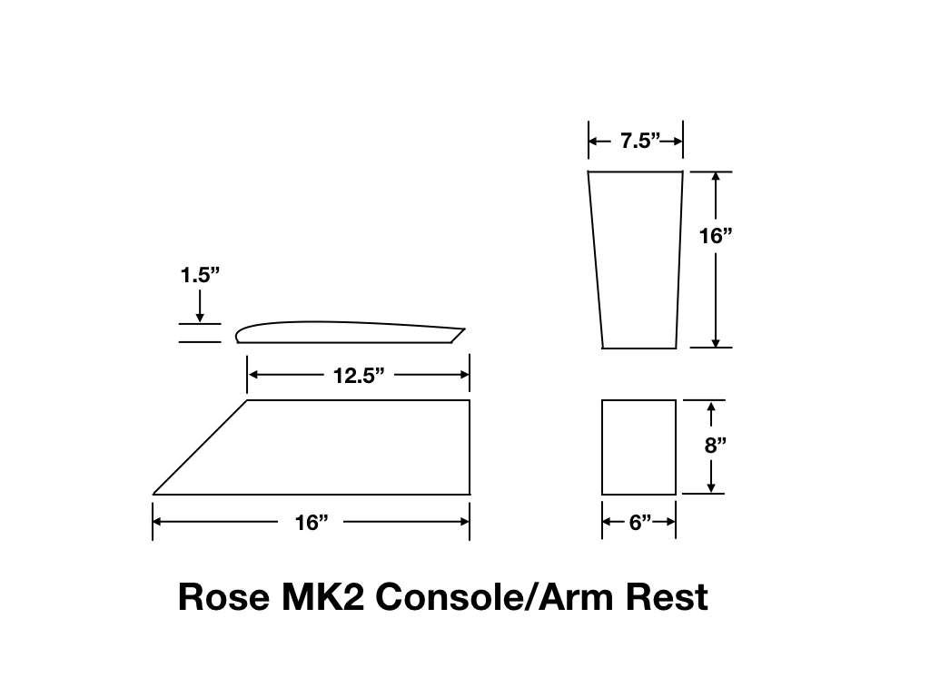
Rose MK2 Console-Arm Rest Dimensions

I constructed the “box” from a 1/2″ PVC panel. I chose the material primarily because it doesn’t absorb any moisture, but I also found that it is very easy to work with – much easier than plywood or some other composite material. A few 1-1/2″ poplar wood braces were also used for extra support. The panels of the box were all cut on a portable construction table saw, the holes for the seat switches were cut with a hand held saber saw, and the holes for the USB ports were cut using a hole saw.

My next step will be to cut matching panels from 1/8″ PVC. These will then be glued to the 1/2″ panels. This will completely cover all of the screw heads and mounting indentations and should produce a nice finished surface for the leather.  Ultimately, I will mount the “box” to the original heater pipe cover and to the prop shaft tunnel as Kevin did.

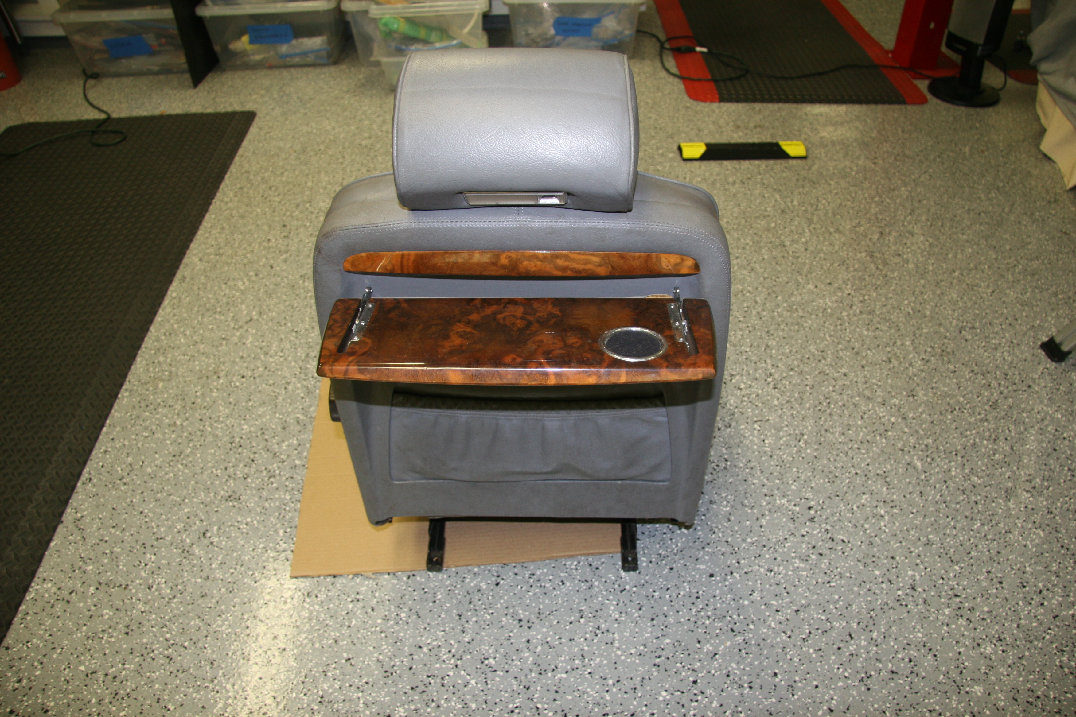
These are a few images with the “box” just sitting (not mounted) in position:

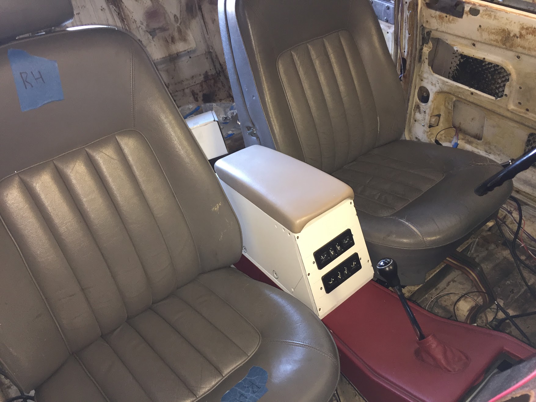
Console Arm Rest RH Front View

Console Arm Rest LH Front View

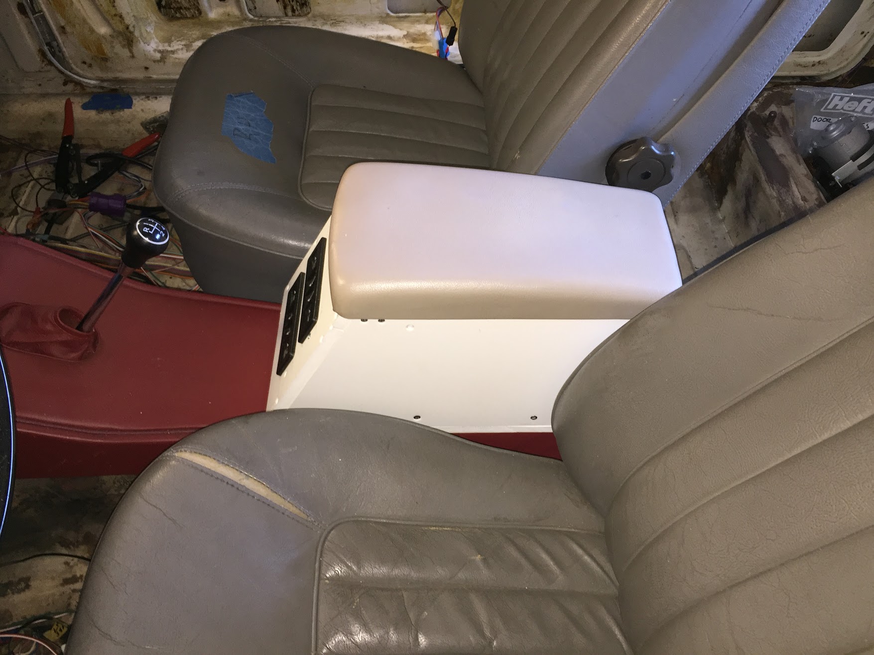
Console Arm Rest LH View

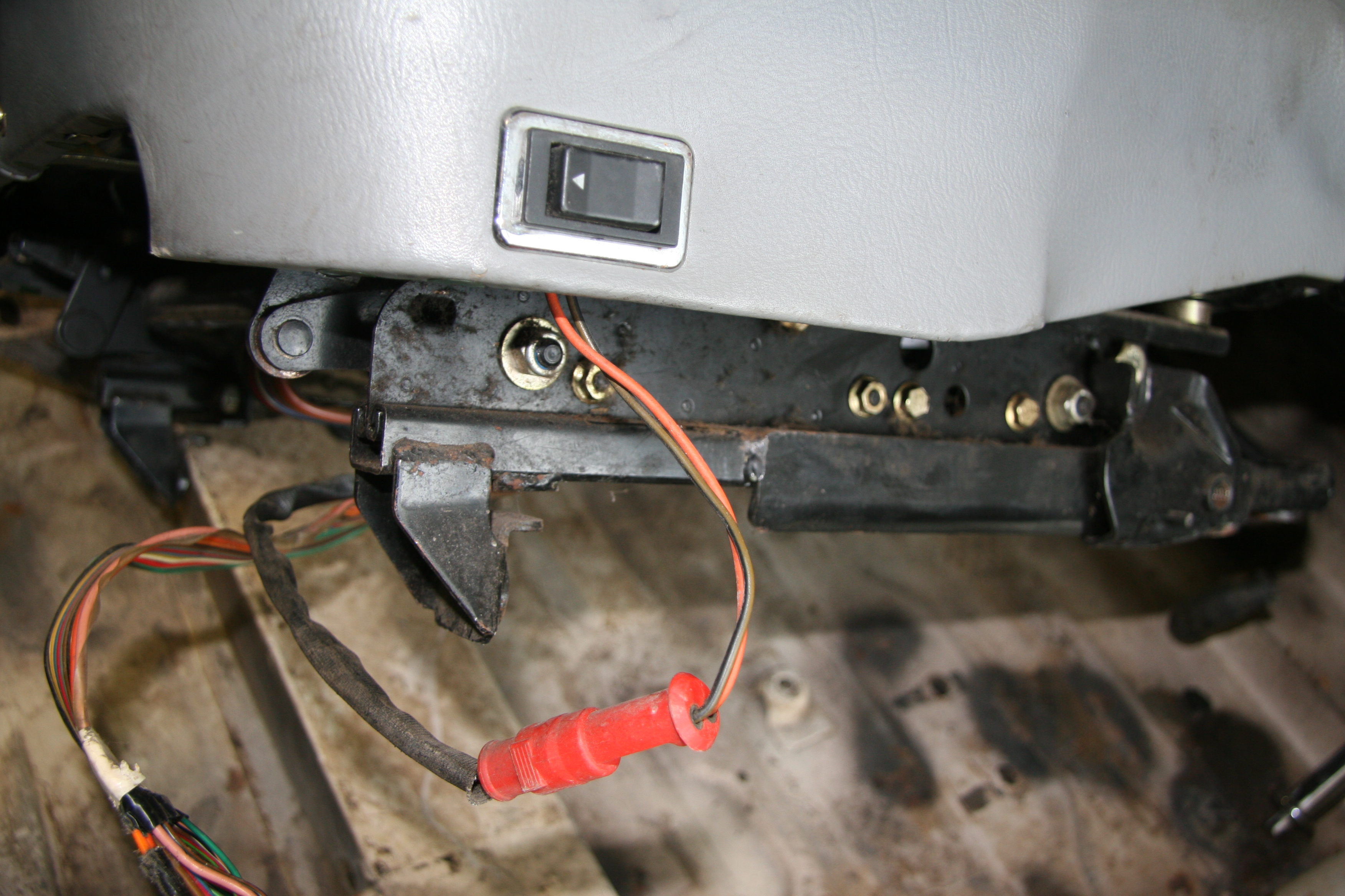
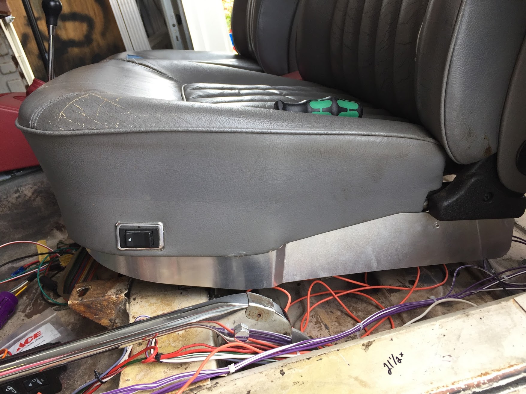
The following two images show the mounting of the electrical switches in the front and the twin USB ports in the rear. The screws in the face plate of the USB mounting bracket will be replaced with black screws. As I mentioned previously, additional sheet metal will be added to the end of the heater pipe cover so that it matches flush with the rear edge of the “box.”

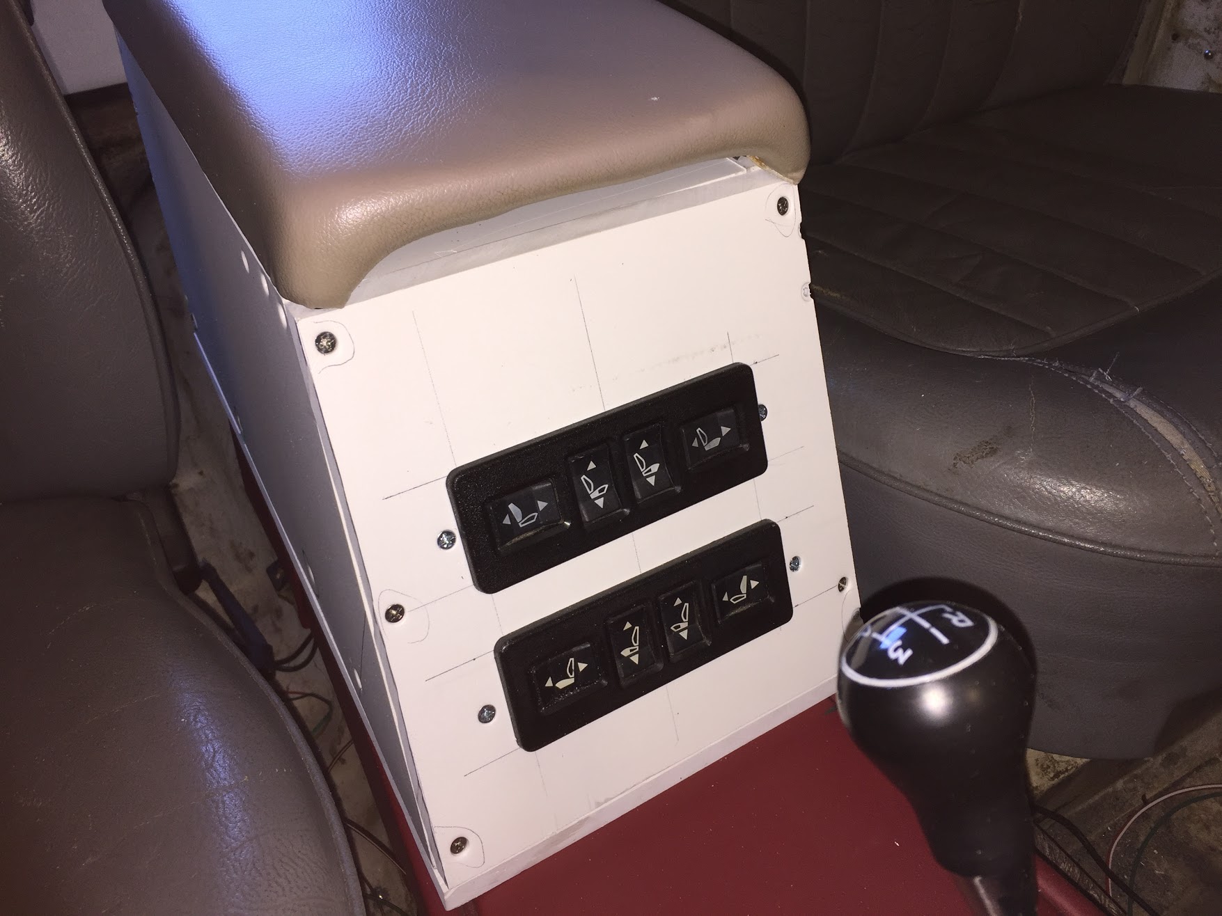
Console Arm Rest Seat Controls

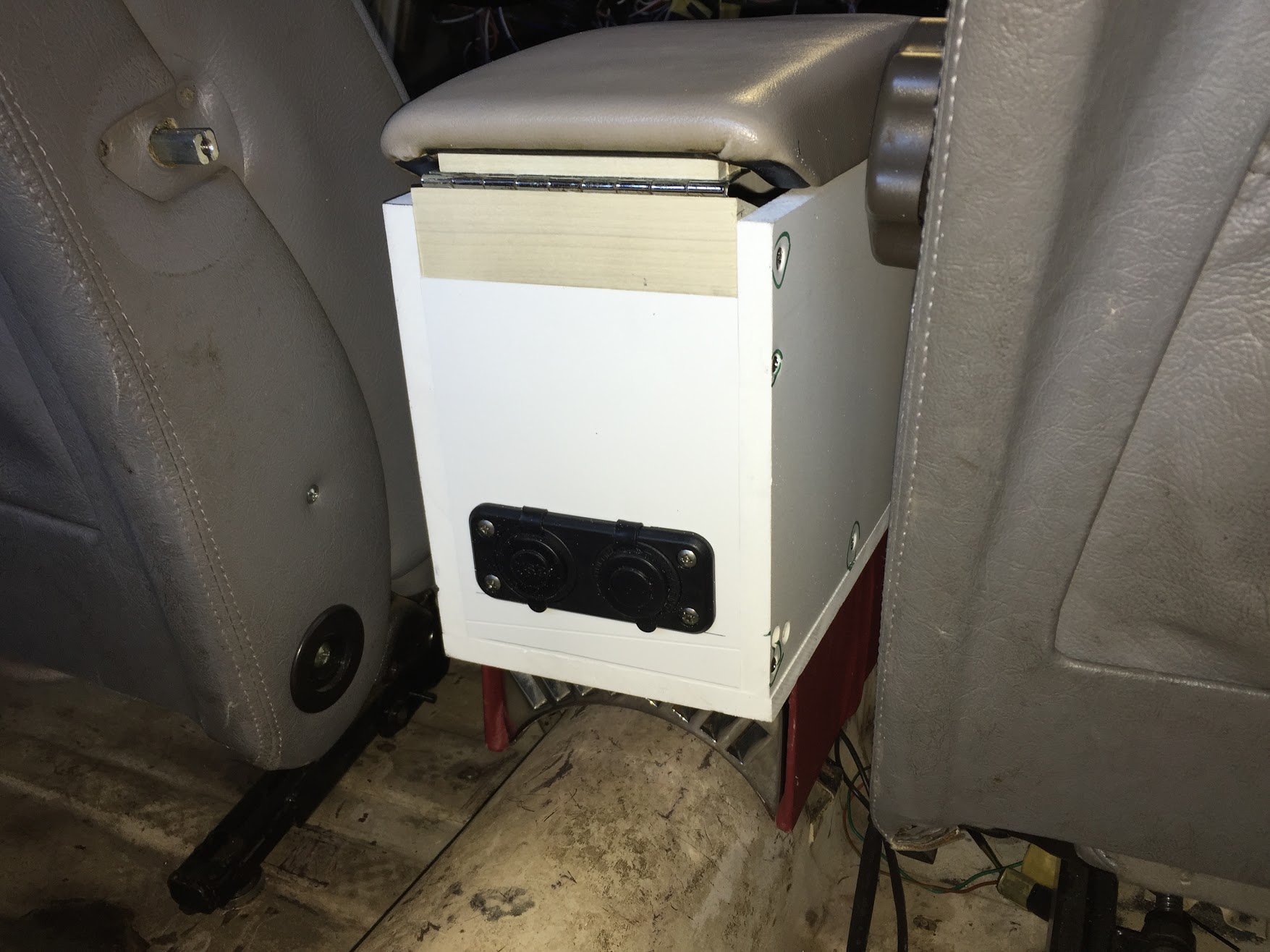
Console Arm Rest USB Ports

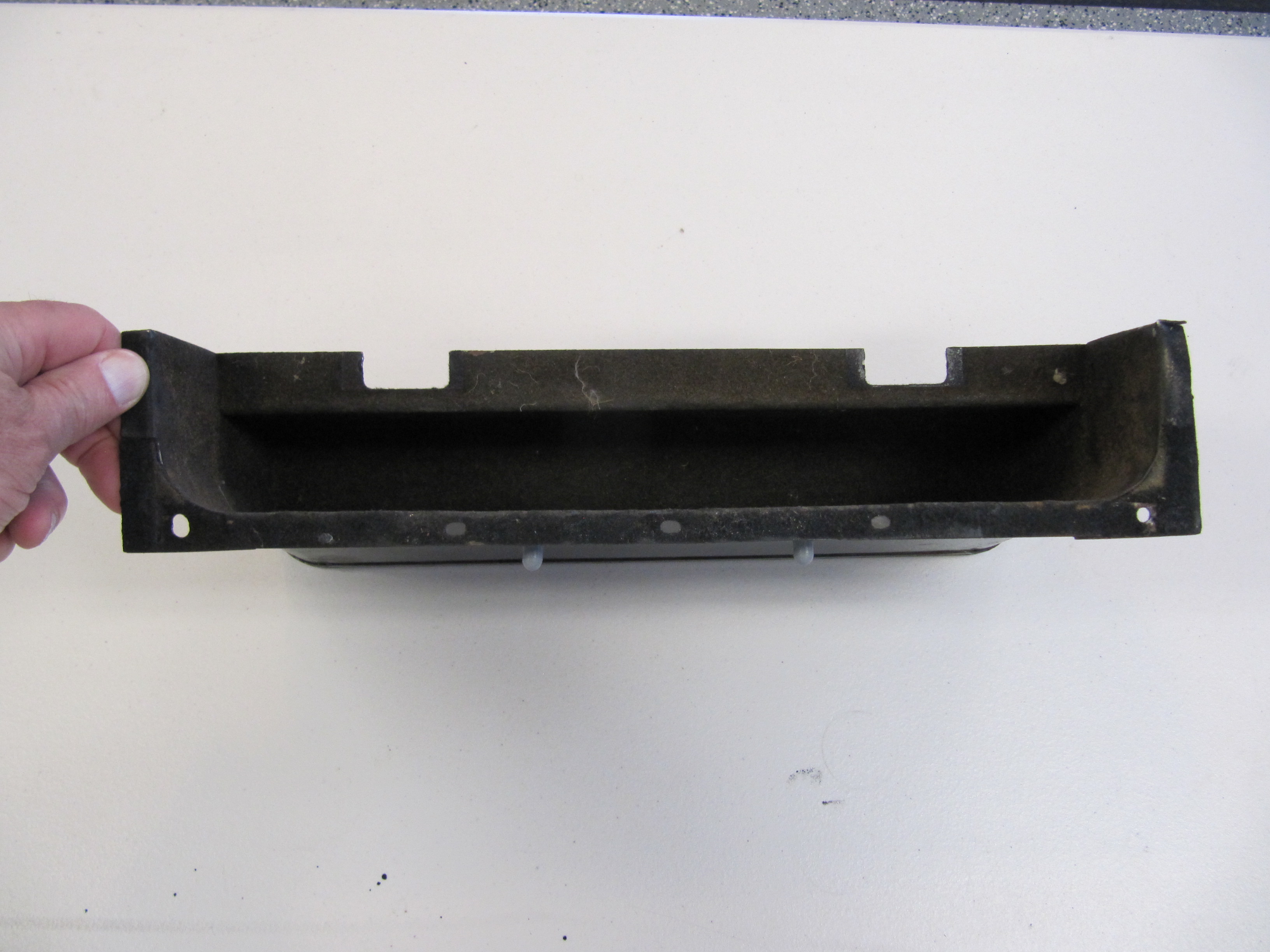
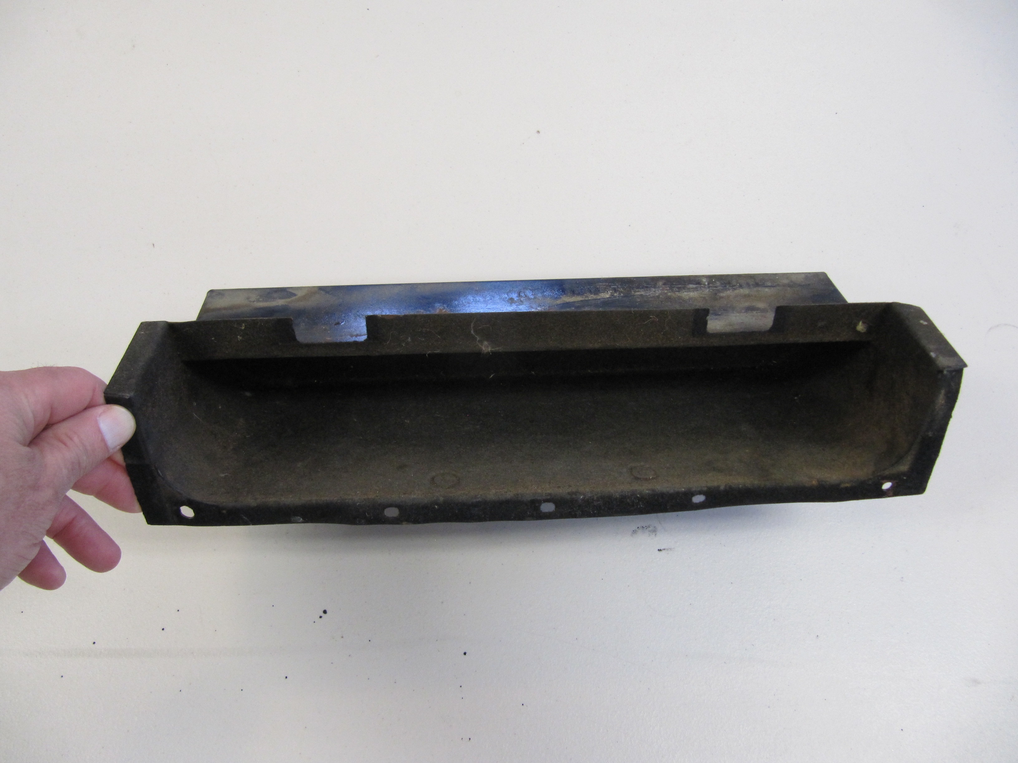
The last two images show the interior of the box with and without the storage tray:

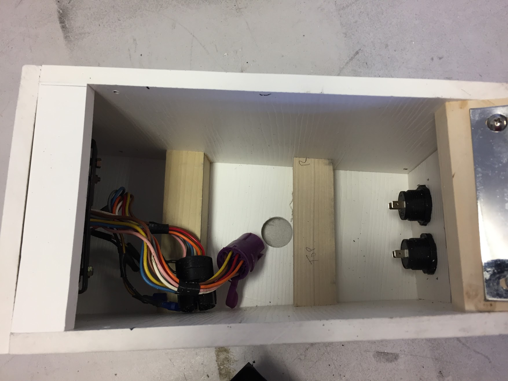
Console Arm Rest Box Interior

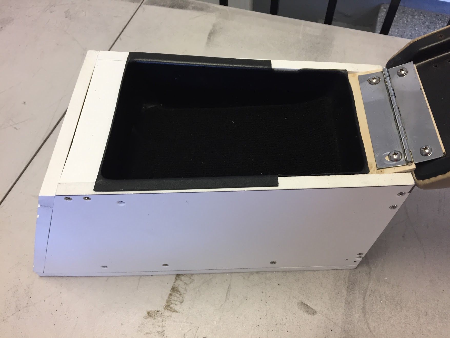
Console Arm Rest Storage Tray

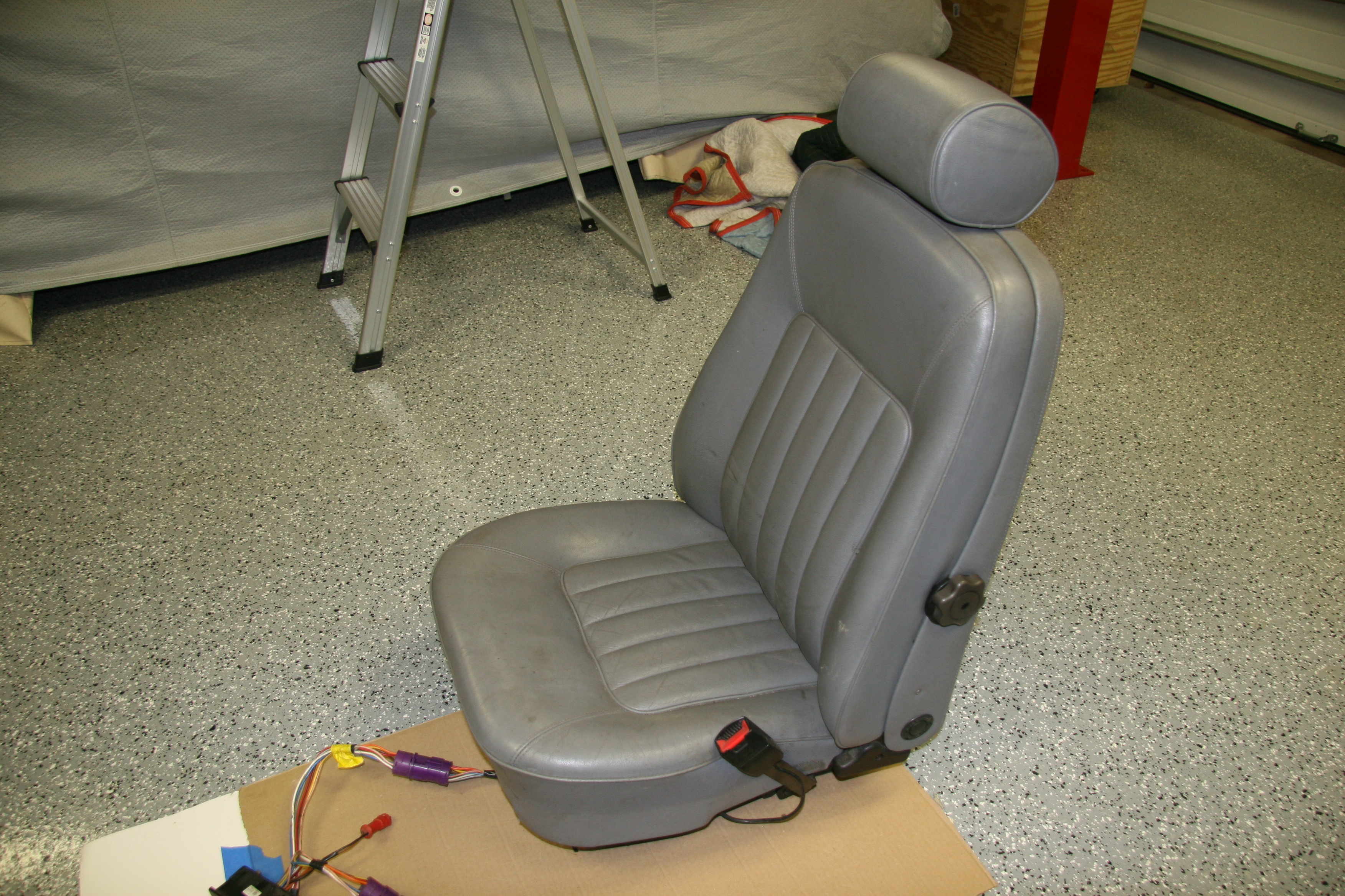
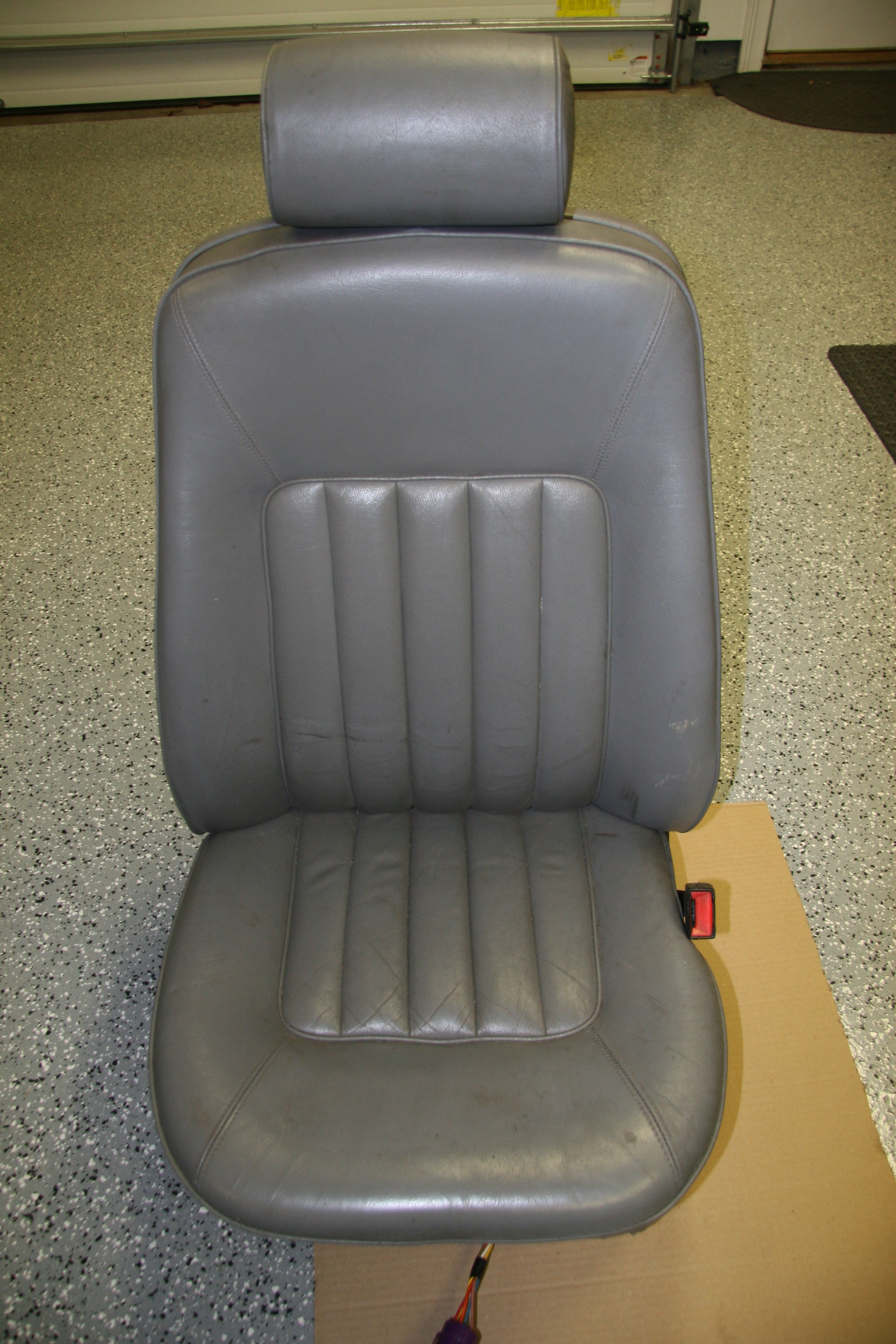
Of course, the beige arm pad, the grey seats and the red original heater pipe cover will all get reupholstered in a single color leather!


Seating

Front Seating

Following considerable thought I have decided to install front seats from a later model Jaguar in my MK2. At first I pursued the original tilting seats that were available from Jaguar as an option at the time. I actually found and purchased a pair. they were in rough shape, but the frames were just fine and that was all I was really after.

Jag MK2 Optional Tilting Seats

Jag MK2 Optional Tilting Seats

Jag MK2 Optional Tilting Seats

Jag MK2 Optional Tilting Seats

However, after seeing the installation of Daimler seats in Ton Tulleken’s restored Jaguar MK2, I decided that I must have the same seats for my restoration! Ton’s site is in Dutch but the photos work in all languages.

I could not locate any Daimler seats in the U.S. so I turned to Ton who is from the Netherlands and he was able to help me. Hendrikus Alkema who runs and owns New and Used Parts Jaguar Daimler in the Netherlands had a full set of 1990 Daimler seats available. I ordered the two front seats as well as all four headrests from the car. The seats came complete with the wiring harnesses and switches.

The seats arrived two days after the order was placed! DHL had them on my doorstep. On one of the seats the lumbar support knob was broken in transit, but Hendrikus sent a replacement to me right away.

1990 Daimler Front Seats

1990 Daimler Front Seats

1990 Daimler Front Seats

1990 Daimler Front Seats

The picnic tables on these seats are particularly nice and much more functional than the ones on the MK2 seats.

1990 Daimler Front Seat Picnic Table

1990 Daimler Front Seat Picnic Table

1990 Daimler Front Seat Picnic Table Open

1990 Daimler Front Seat Picnic Table Open

The seats I purchased are slightly different than Ton’s as my headrests are not adjustable. I will have the seats recovered over new seat foams when the time comes.

Of course, the primary advantage of these seats is their adjustability. Each seat has four motors. Two for the lower and two for the upper cushion. The seats also have seat heaters (non-functional apparently) and the driver’s seat has a memory function.

Most folks cut down the height of the floor brace in the interior to install the modern seats; however, Ton did not do that and I am going to at least try it this way before cutting them back. I like the idea of being able to go back to the original seats if I, or another owner, decided to do so in the future. As Ton did, I made a brace for the seat frames from angle iron and had them welded to the frames. I will then drill them for mounting through the original holes of the seat supports into the floor brace.

Front Foot on XJ40 seat frame

Front Foot on XJ40 seat frame

XJ40 seat frame front foot

XJ40 seat frame front foot

XJ40 seat frame front foot removed

XJ40 seat frame front foot removed

The front foot shown in the image above must first be removed.

New front mounting bracket in place with front foot removed

New front mounting bracket in place with front foot removed

The image above shows the new bracket in place prior to welding to the seat frame.

Floor Brace and seat mounting captured nuts

Floor Brace and seat mounting captured nuts

The image above shows the four holes with captive nuts in the floor brace that are used to mount the new seat frame to the floor.

The wiring had its own set of challenges. Details about the wing may be found in the “Building a Wiring Harness” post.

Ton suggested making “skirts” for the lower portion of the seats so that the seat mounting frames would not be visible when the door is opened. I followed suit. Brandon Tyree, metal welder/fabricator at Gassman Automotive, made the skirts from sheet metal for me. These will be covered with leather/vinyl when the interior upholstery is finished.

Brandon welded metal tabs to the seat frames so that the sheet metal skirts can be screwed to the tabs to mount them to the seats. These are designed so that the skirts will move with the seats when the power functions of the seats are used.

LH Side Front Seat Skirt

Locating Tabs for LH Side Front Seat Skirt

LH Side Front Seat Skirt Installed


This is an image of his finished product:

Ton Tulken’s Front Seat Skirts

Original Seat Mounting

Seat Supports

Details on the removal of the seat runner assemblies or seat supports may be found in the disassembly note, entry 45 https://valvechatter.com/?p=1803, and entry 6 https://valvechatter.com/?p=297.

Each support is mounted to the floor brace with four 1/4″ – 28 x 5/8″ pointed tip, slotted machine screws with flat and shakeproof washers. The rear mount for the seat to the seat support is a 1/4″ – 28 x 1″ hex head bolt with shakeproof washers. An insulation pad was found cut to fit under each seat support.

I removed the vinyl from each of the four supports, media blasted them  and painted with POR-15 to be covered with new vinyl later.

Seat Supports

Seat Supports

Seat Supports

Seat Supports

Seat Supports

Seat Supports

Seat Supports

Seat Supports

I media blasted the four seat supports and prepared them for painting:

Front Seat Support

Front Seat Support

Front Seat Support

Front Seat Support

Seat Supports Painted

Seat Supports Painted


Radio/Heater Control Panel

Just as a trial run – I have no leather yet! – I assembled the control panel including the radio, heater control levers, and the speaker grill. I am going to be adding locations for air conditioning control switches and I needed to take a close look at the assembled panel to identify the best spots. I will not be installing a speaker behind the speaker grill, so I will need to place a “blackout” panel behind the grill to prevent one from looking through the grill.

The control panel attaches to the bottom of the newspaper tray and to a bracket on top of the gearbox cover. It will be covered in leather/vinyl to match the interior color.

Radio Control Panel

Heater Control Lever with Fasteners, Escutcheon and Identifier Plate

I first inserted the chrome escutcheon with its identifier plate through the mounting holes on the RH side of the panel. I then placed two 5.5mm spacers on each threaded mounting post followed by the lever assembly. The collection was then secured with a shake proof washer and a 10-32 stainless hex nut on each post. The RH side lever is for the “car/screen” control. The Identifier plate is to the inside of the escutcheon. The black control lever knob can then be attached with a small #6? fillister head machine screw.

The procedure was then repeated for the air temperature control lever on the left side of the assembly. This lever has an identifier plate with “hot/cold” lettering, again placed to the inside of the panel.

Heater Control Levers in Place, Front View

Heater Control Levers in Place, Rear View

Hot/Cold Control Lever Cable Mountings

Car/Screen Control Lever Cable Mountings

Installation of the radio was next. After removing the locking nuts the face plate and the control knobs from the radio I inserted the radio into the radio control panel from the rear. I then straightened the radio on the control panel, installed the radio faceplate, and the locking nuts on each of the control knobs. The control knobs were then pushed in place with the volume on the left and the channel selector on the right.

Radiomobile Radio Installed, Front View

Radio Installed, Close-up

Radio Installed, Rear View

I still need to include the mounting of the radio support arms in this post and will do so soon.


Interior

Rear View Mirror

The parts manual does not provide much information on the rear view mirror. The assembly apparently came from Lucas and was installed as an assembly. Perhaps there is Lucas documentation available someplace, but I did not find it. My original mirror was pretty dirty and the height adjustment post would not tighten properly. A new mirror assembly is available from SNG Barratt, but I decided to use my original. I did purchase a new “Interior Mirror Mounting Clamp/Boss – C20697/1”, that addressed my sliding adjustment problem:

Mirror Mounting Clamp/Boss

Mirror Mounting Clamp/Boss

I also had my original mirror re-silvered by Tim Inman at Inman Historic Interiors www.historicinteriors.com/Resilvering.html The resilvering costs about $65 including shipping. The finished product looked like new. Reassembly is pretty easy but it does require carefully bending four tabs that secure the tensioning spring for the mirror ball joint. The image below shows the mirror casing and the spring assembly with adjustable post.

Rearview Mirror Before Assembly

Rearview Mirror Before Assembly

The image below show the installation of the post and tensioner spring with mounting plate:

Installing Rearview Mirror Components

Installing Rearview Mirror Components

The image below shows the tensioner spring plate tabs bent back to secure the spring plate:

Tensioner Spring Tabs bent into Position

Tensioner Spring Tabs bent into Position

A very fine sprung wire holds the tensioner plate to the mirror assembly as seen in this image:

Rear View Mirror Retaining Spring

Rear View Mirror Retaining Spring

The mirror casing cleaned up with some polish and hand buffing:

Polished Mirror Casing

Polished Mirror Casing

The final step was popping the mirror back into the casing to complete the job!

Resilvered Mirror Installed

Resilvered Mirror Installed

Of course, the generous use of Walnut veneered wood and supple leather hides make a Jaguar!

Wood Trim

I will have all of the wood professionally refinished. possible vendors include:

http://www.classicdashboards.com/gallery-jaguar-restoration-photos.html

Classic Dashboards is operated by Simon Lorkin who is located in France.

British Autowood operated by Saul Chaplin is in Altamonte Springs, Florida: http://www.britishautowood.com/index.htm


Leather Trim

I have not yet decided if I will have the leather and vinyl work custom stitched or if I will go with one of the primary suppliers:

John Skinner at: http://www.jaguar-trim.co.uk

or,

BAS Ltd. at: http://www.basjaguartrim.com/mk2daimler250.htm

or,

Aldridge Trimming at: http://www.aldridge.co.uk


“Cubby” Glove Box

“Cubby” Glove Box

The “Cubby” as the glove box is referred to is located on the RH side of the dash fascia.

Cubby Door

Cubby Door

It has a hinged wooden door and the box itself is a heavy cardboard material. My original is in excellent shape but unfortunately suffers from a lingering musty odor from years of damp car storage so I will not be able to use it. The image below shows the components of the glove box assembly including a newly chromed trim piece.

Cubby Box Components and Fasteners

Cubby Box Components and Fasteners

The glove box is mounted to the RH Wood Facia Board Assembly with the following components:

Cubby Box Components and Fasteners

Cubby Box Components and Fasteners

Dash

Dash Components

Air Distributor Box

Details on the box which sits below the dash can be found under the Heater post: https://valvechatter.com/?cat=103

Mounting Bracket for Radio Control Panel

This bracket shares the mounting bolts with the air distributor box, and mounts behind and above it.

Mounting Bracket for Radio Control Panel

Mounting Bracket for Radio Control Panel

Powder Coated Mounting Bracket for Radio Control Panel

Powder Coated Mounting Bracket for Radio Control Panel

Air Distributor Box Installed

Air Distributor Box Installed

Instrument Panel Assembly

While the speedometer and tachometer are placed directly in front of the driver in the MK2, the rest of the gauges and most of the switches are located in a central panel in the dash referred to as the Instrument Panel Assembly. The panel is mounted with two thumb screws at the top corners of the panel that when released permits the panel to swing out on hinges.

Information regarding the individual gauges, instruments, and switches may be found under the “Gauges, Instruments and Switches” post.

Instrument Assembly Panel

Instrument Assembly Panel

Newspaper Tray

The Newspaper Tray sits immediately below the gauge panel in the center of the dash.

Newspaper Tray

Newspaper Tray

It is secured with two #10-32 nylock nuts and two rubber washers on the mounting studs.

Newspaper Tray

Newspaper Tray

Newspaper Tray

Newspaper Tray

Newspaper Tray

Newspaper Tray

The newspaper tray has a grey flocking on the interior of the envelope. At this time I am not sure how I will replicate the flocking, but I am sure that I will figure out something. I media blasted the tray to prepare it for powder coating.

Newspaper Tray

Newspaper Tray

Newspaper Tray

Newspaper Tray

Right and Left Fascia Board Assemblies

For the purpose of testing my electrical system, gauges and instruments, I installed my yet to be refinished dash fascia boards. The driver’s side fascia board houses the Handbrake “ON” Position and Brake Fluid Container Level Warning Lamp,  the speedometer and the tachometer with internal clock. The speedometer includes warning lamps for high beams, low fuel and ignition charging. The passenger side fascia board houses

the “Cubby” glove box that incorporates a light that illuminates when the door is opened.

As the Service Manual suggests, fitting and removing the driver’s side Fascia Board is made easier (though not necessary) by dropping the steering column to the seat. The central instrument panel was already removed from the car.

Since this is not my final installation I did not install the small twisted (steady) brackets nor the top brackets for the mounting of the screen rail dash top.

Driver's side fascia board

Driver’s side fascia board

Passenger side fascia board

Passenger side fascia board

I did install the LH and RH mounting brackets to the wooden fascia as seen in the images above. The brackets were all cleaned, bead blasted and repainted before mounting to the fascia boards.

Fascia Board Refurbished mounting hardware

Fascia Board Refurbished mounting hardware

While I did not get a photograph of the wood when I reinstalled the renewed brackets one can see in this image that outside brackets for both fascia boards have studs that go through holes in the car’s body bracing and are then secured with “special” oval washers, split washers and nuts.

Driver's side fascia board outside mounting bracket

Driver’s side fascia board outside mounting bracket

The inside brackets for both fascia boards have rubber seals that I assume are to block light that might escape from behind the instrument panel. Two #10 – 32 x 1/2″ machine screws mount through the inside brackets into the car’s body.

Passenger side fascia board internal mounting bracket

Passenger side fascia board internal mounting bracket


Cubby Box Door Hinge

The Cubby Box Door Hinge is a chrome sliding hinge, being in excellent condition, I simply cleaned and polished the hinge. It is attached to the Cubby Box with four chrome slotted wood screws.