July 2, 2005
Control Head (Trafficator)
Well, I have been putting off the task of rebuilding the control head to preparte it for installation in my Moto-Lita wood rim steering wheel. I rebuilt the original control head when I was in college and I don’t recall it being a fun task. Although, back then I did so without any instruction. Today I have the benefit of helpful tips from Norman Nock, Michael Salter, Steve Byers, John Trifari and Tracy Drummond and others. The notes below and some of the images are “borrowed” from their work. Tracy’s photos were particularly helpful.
For starters I now know that the way to begin is not to pry up the bent tabs at the back of the unit! Instead, the process is much simpler but less obvious. Turns out the whole job was not as bad as I had remembered.
In my case I needed to completely rebuild my control head because the signal lever was broken and because I needed to install new wiring. I also wanted to improve the finish of the Bakelite head which had turned a bit brown with age. If one only needed to replace the wiring the suggestions from Michael Salter proved to be very helpful. That was my first step.
Read through these instructions completely before starting the disassembly!! If you don’t want to try this then I understand that Vic Wright (cv@spiritone.com) does a great job of rebuilding used units!
On the steering wheel, you will see three set screws on the steering wheel hub, forward of the spokes. Loosen (probably remove, to avoid losing them) the screws. The four wires that go to the control head need to be disconnected from the harness at the front of the car not far from where they exit the long stator tube at the steering box. The job is made easier if one simply cuts the bullet connectors off the wiring and then solders a wire or ties fishing line to the wire. Having the line attached to the wiring will make inserting the new wiring much easier than it would otherwise be. The line should just rest in the steering column until the replacement is ready to install. The control head with a short stator tube and the wiring can then be removed from the steering column by pulling straight out (not twisting). Neil Trelenberg suggests drawing a line on the stator (short and long) tube with a felt marker as a guide for realigning later.
Now to the disassembly of the control head unit:
First, carefully pry the horn button trim ring away from the bakelite head being careful not to scratch it.

Trafficator Rebuild Image 1
Once the horn button is loosened, the horn spring will be revealed. Its small diameter end faces to the bakelite head. The laminated blades of the horn switch secured by two brass screws also become evident.

Trafficator Rebuild Image 2
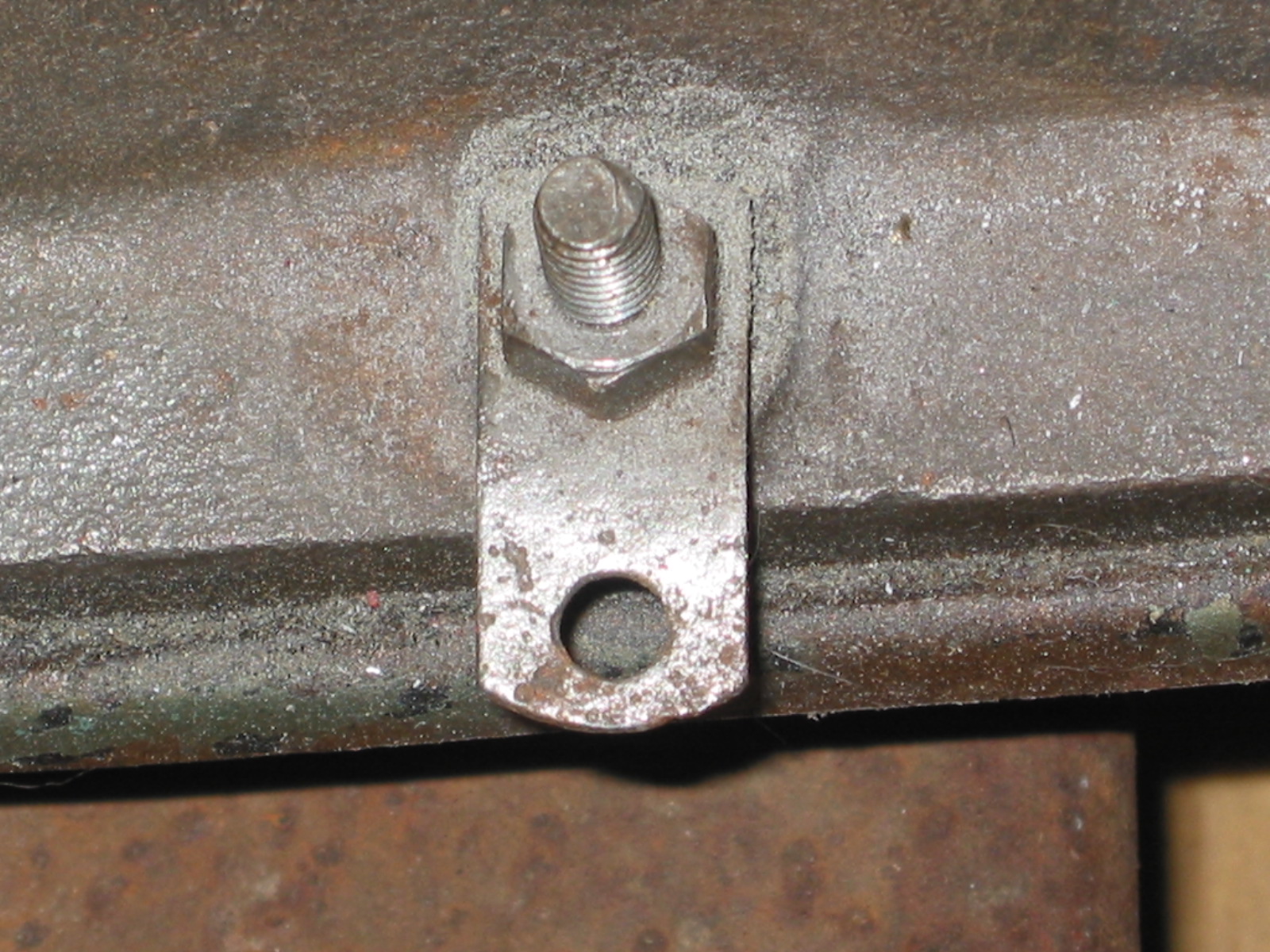
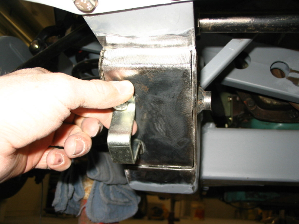
Examine the entire assembly. On the back of the unit, viewed from the side, a small tab bent down into a slot can be observed.

Trafficator Rebuild Image 3
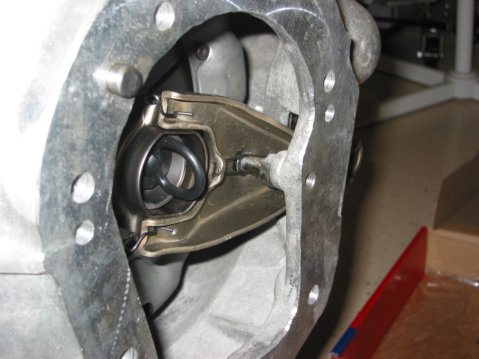
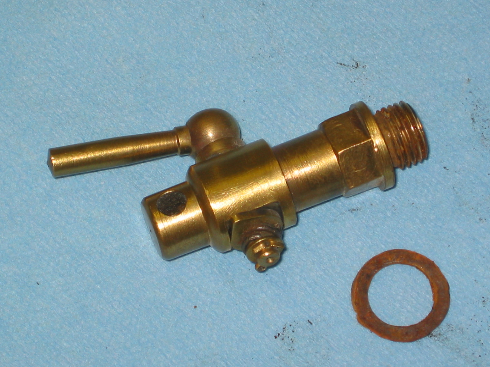
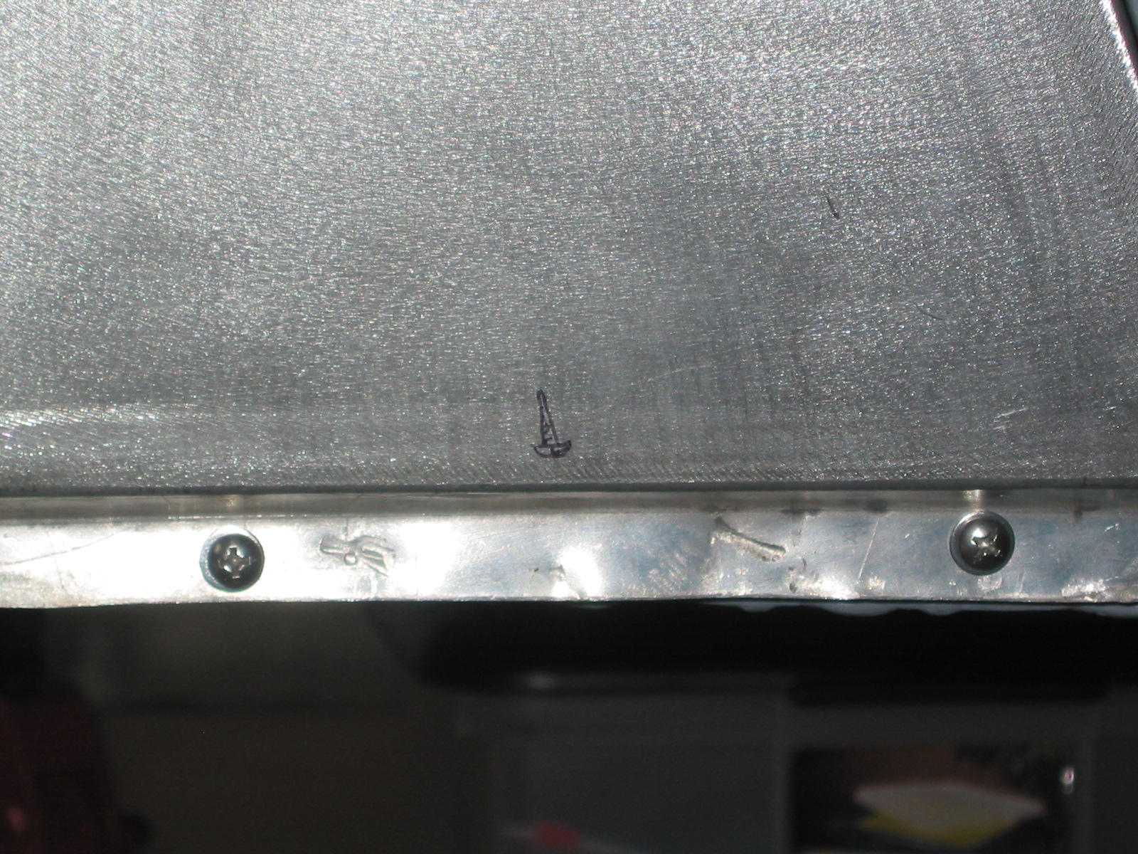
The tab can be pushed up so that it slides on the flat plate and the unit can be rotated slowly. Doing so provides access through 3 holes in the base mount plate to 3 slotted screws.

Trafficator Rebuild Image 4
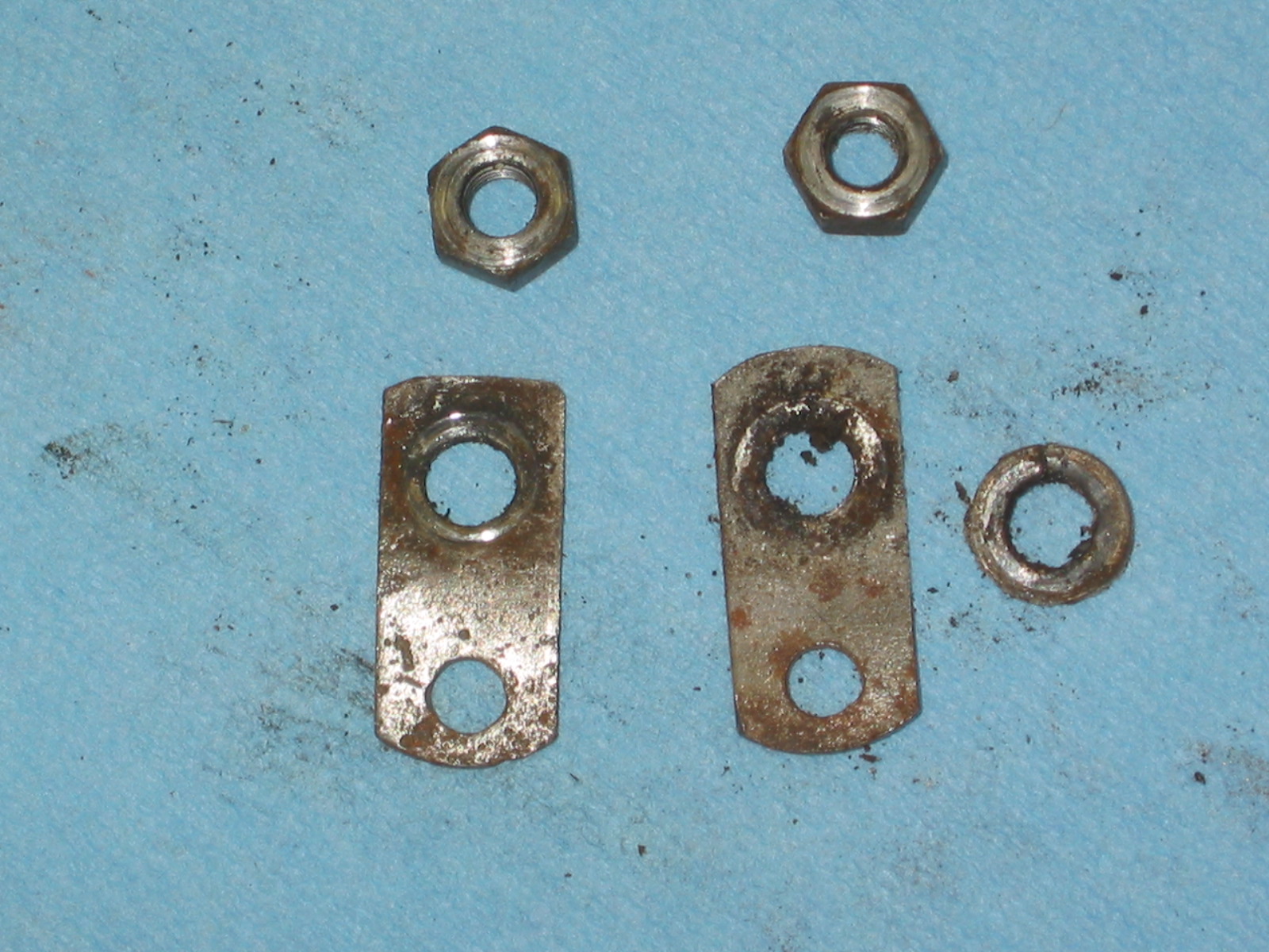
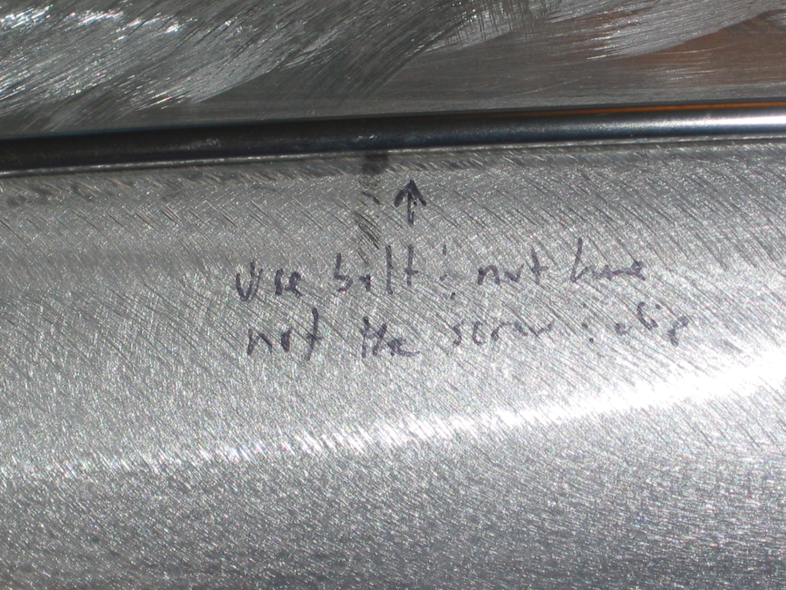
Before removing the three screws, make a note or reference mark of how the two halves of the unit secured by the three screws goes together. Then remove the screws. The correct orientation of the turn signal lever is straight up, but if the two halves are oriented incorrectly, the turn signal lever will be either pointed down, or off to the side.

Trafficator Rebuild Image 5
The stator tube, base plate, locating plate, the base mount plate and assorted washers and spring can then be separated from the bakelite mounting plate and head. This assembled unit does not need to be disassembled. It can be pulled off the wires and set aside for assembly later.

Trafficator Rebuild Image 6
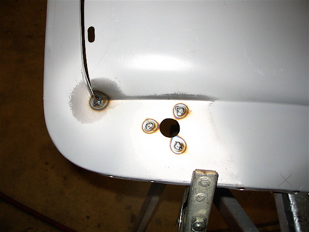
Examine the back of the mounting plate. There are six nuts visible. Three are for the turn signal switch, two are for the horn (one goes through the brass gound ring) and the one without an attached wire is to hold the head and the mounting plate together (It is barely visible in the photo under the wiring sheath). Make a drawing to illustrate the color code and where each of the wires should reconnect to its proper fitting.

Trafficator Rebuild Image 7
If your plan is to install a new wiring harness only and you do not wish to disassemble the control head to access the turn signal switch it is IMPORTANT to install the new wires onto the screws one wire at a time.
A. The screw on the right in the photo is accessed under the horn button. Hold it with a screw driver and loosen the nut holding the wire, remove the nut, change the wire, refit and tighten the nut.
B. The nut second from the right is held in place by a hex head screw recessed in the bakelite mounting plate. The turn signal lever must be moved so that it is aligned behind the screw/nut. It will hold the screw in place permitting removal of the nut and old wire, change the wire and refit and tighten the nut. Do not let the turn signal lever slip while doing this procedure or you will likely be disassembling the complete unit!
C. Reposition the turn signal lever to the center position and repeat B. above for the screw/nut located third from the right.
D. Move the turn signal lever behind the screw/nut located fourth from the right and repeat B. above.
If all you are doing is replacing the wiring you are finished. Leave the screw/nut to the far left, through the horn ground ring, alone.
Feed the wire through the base plate and the stator tube. Reinstall the three base plate screws with the trigger opposite the turn signal lever. I found it easiest to install the screws with the unit on its side. Don’t forget to then reposition the thin plate with the locating tab to the slot and push it down. Reinstall the horn button, spring and chrome trim ring. Note that the button and ring have a locating notch that matches up with the bakelite head.
I recommend cutting the bullet connectors off the wires, solder the wire or tie the fishing line left in the steering column, to the new wires and slowly pull the new wiring harness through the stator tube and out the end of the steering box. The fit of the harness in the tube is tight so it might be best to tape the wire ends together as they are pulled through. The short stator tube fits down and into the longer stator tube in the column. The tubes go together in only one orientation, directed by the dimples found on the side of the short tube.
If you are installing the control head into a non-stock wooden steering wheel you may need to install a shim (I used the plastic top of a yogurt container) inside the hub between the hub and the control head to move the control head toward the driver slightly so that the turn signal lever does not contact the wheel ring. Then reinstall the three set screws to tighten the control head to the wheel hub.
Cleaning or repairing the turn signal mechanism.
Remove the two screws holding the laminated blades of the horn switch under the horn button. The horn switch will lift out. The third screw can then be removed and the bakelite head can then be separated from the mounting plate.

Trafficator Rebuild Image 8
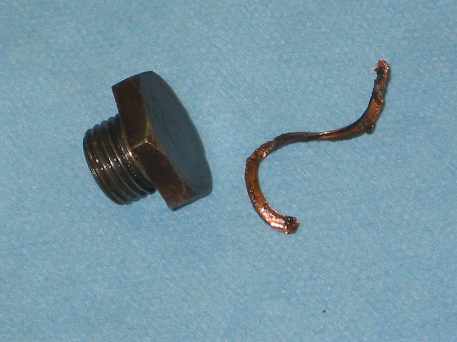
The turn signal lever is attached with one screw to the back of the bakelite mounting plate. Underneath it is a curved wire with a spring on each side of the lever.

Trafficator Rebuild Image 9

Trafficator Rebuild Image 10
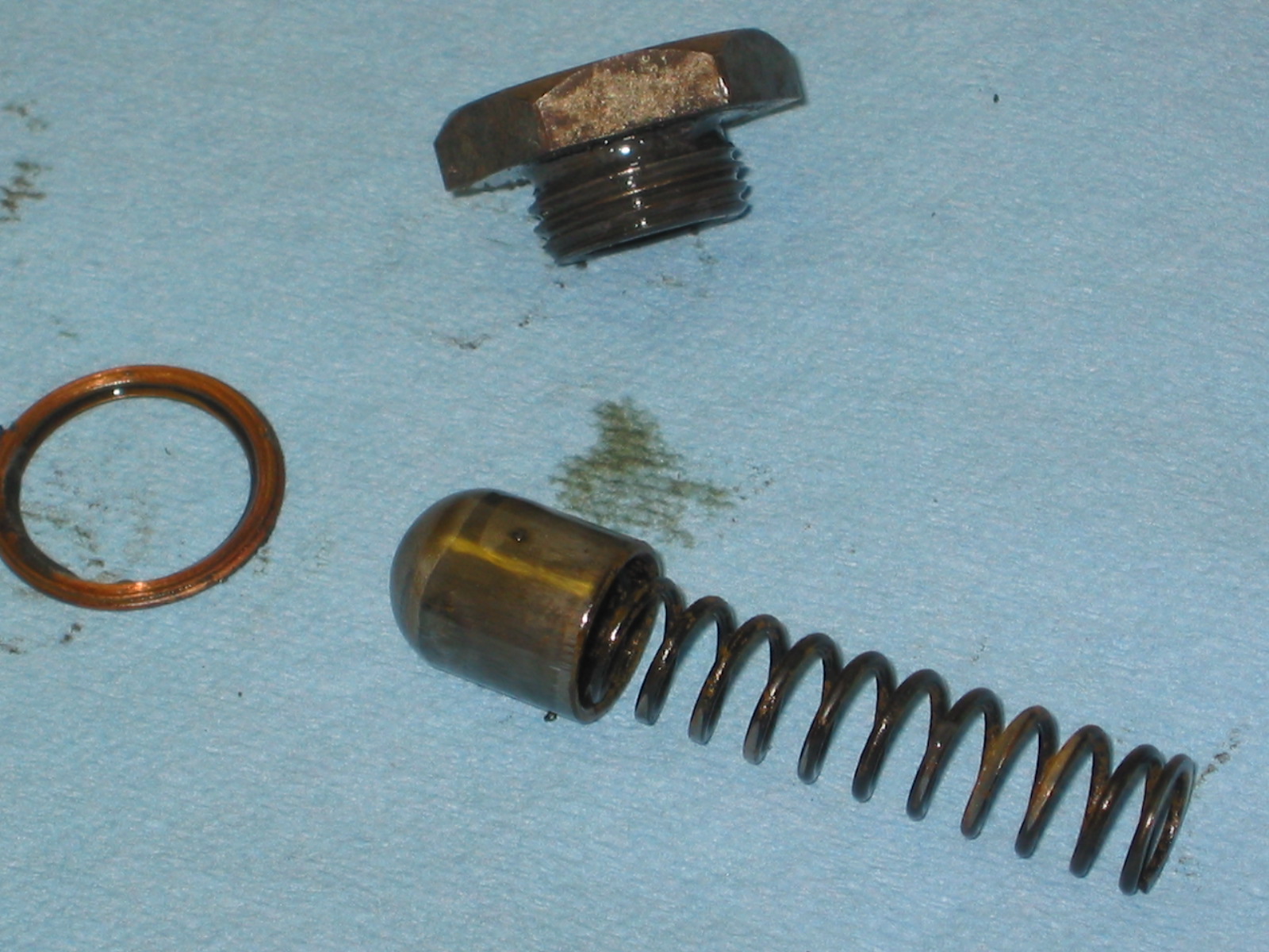
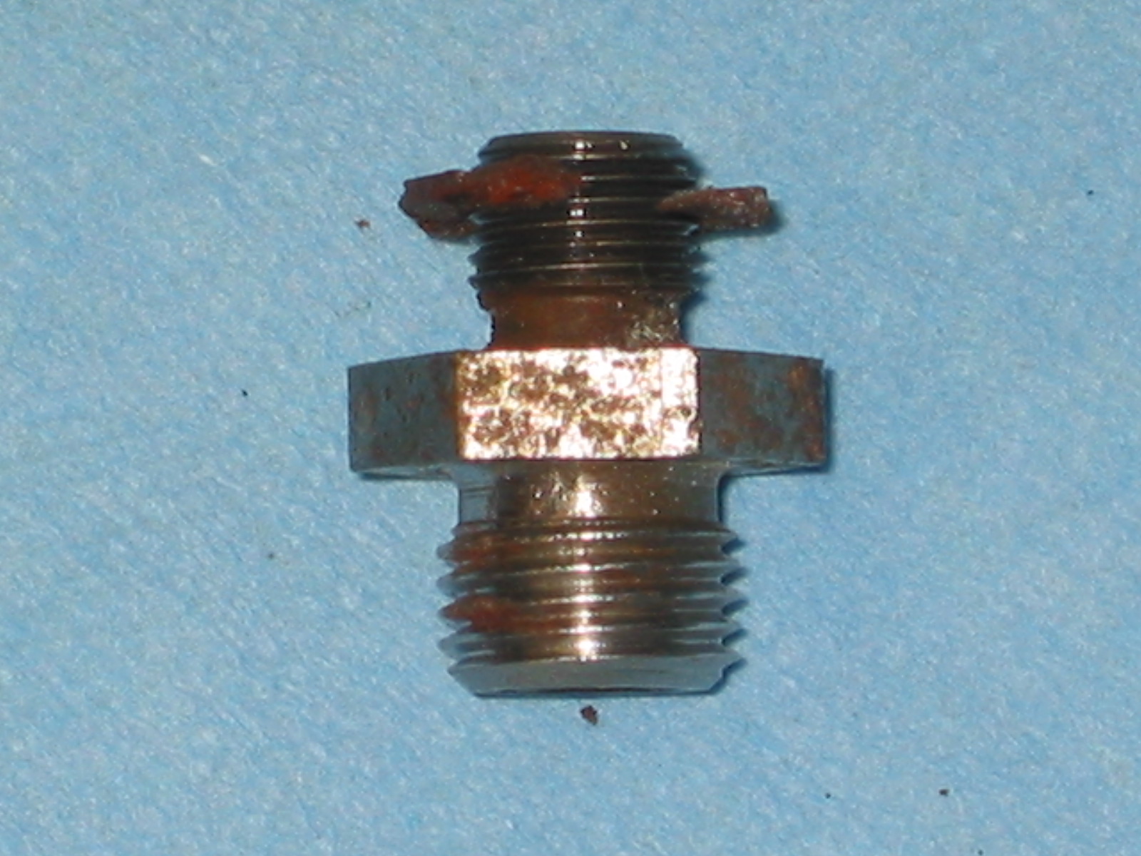
There is another little spring and ball at the bottom of the turn signal lever.

Trafficator Rebuild Image 11
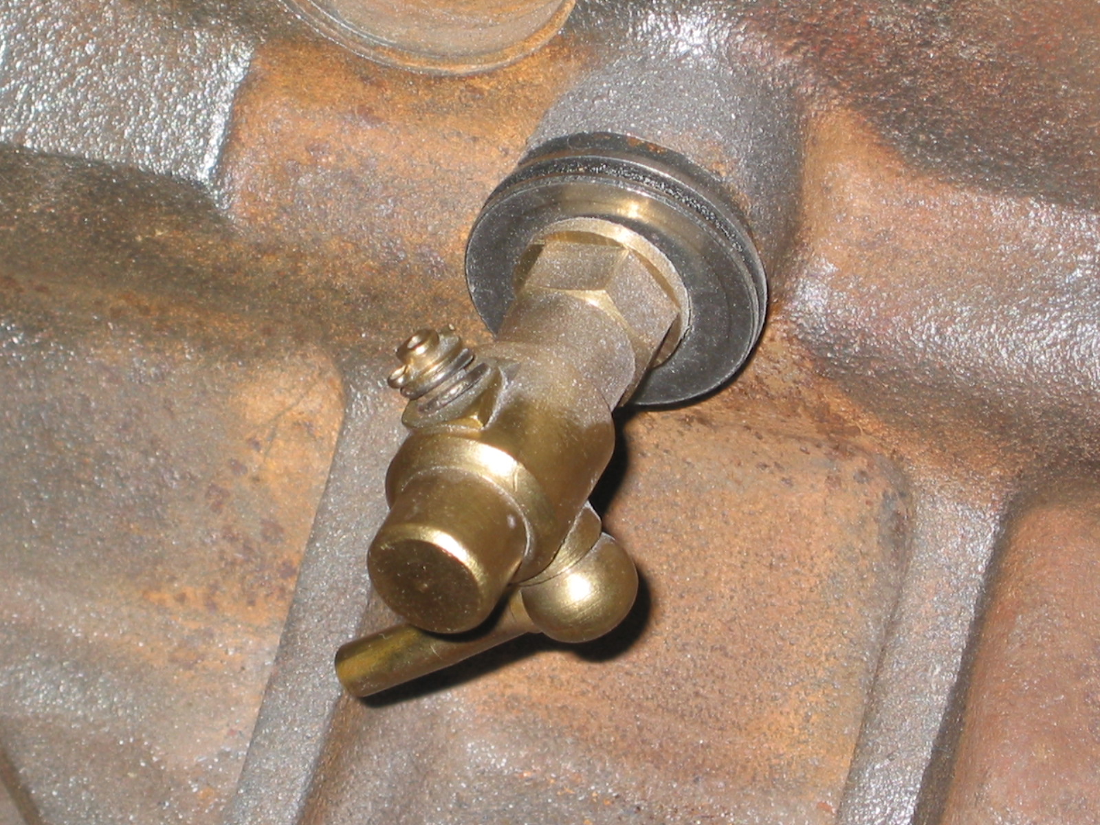
If you carefully remove the single screw to separate the lever from the assembly, the springs and small parts should stay in place. Note how they should be reassembled, then take apart, clean and lubricate with a little lithium grease.

Trafficator Rebuild Image 12
If you experience an explosion of parts, don’t be alarmed. It will all go back together! All components are identified in the photo below:

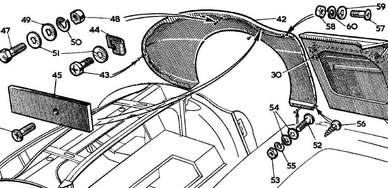
Trafficator Rebuild Image 13
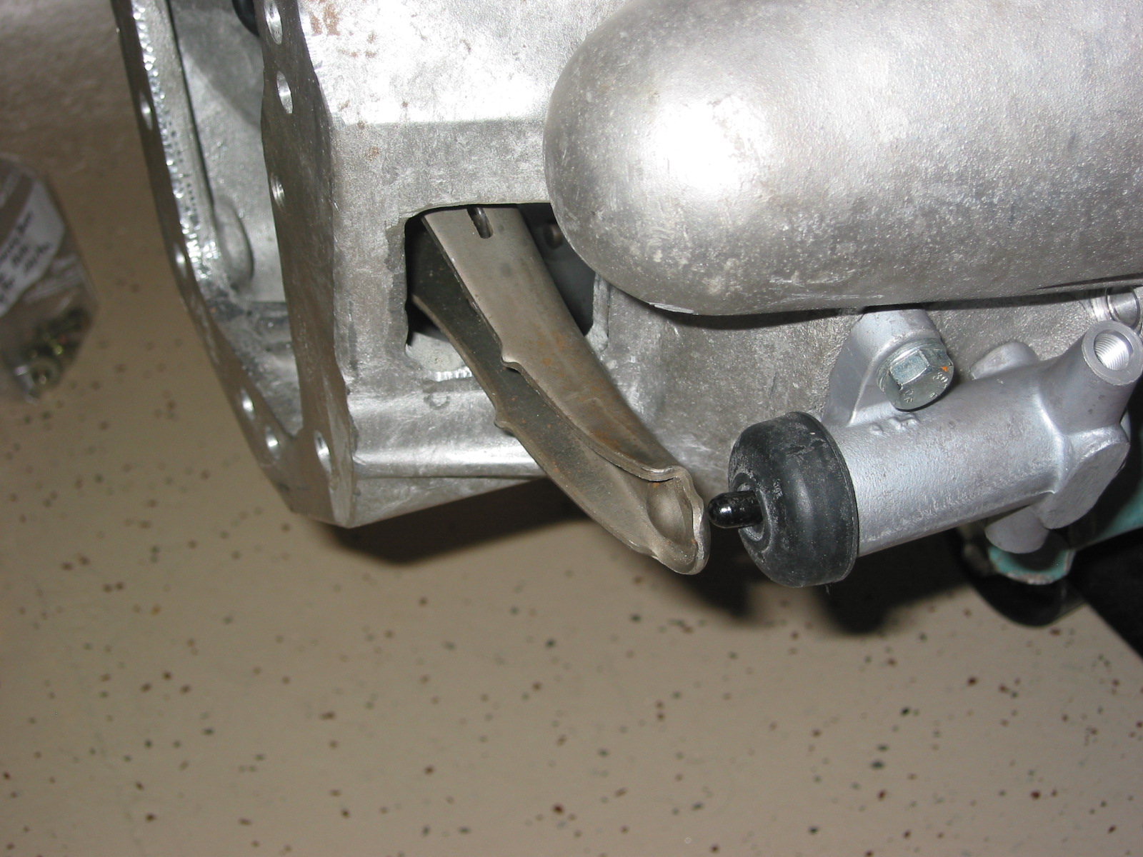
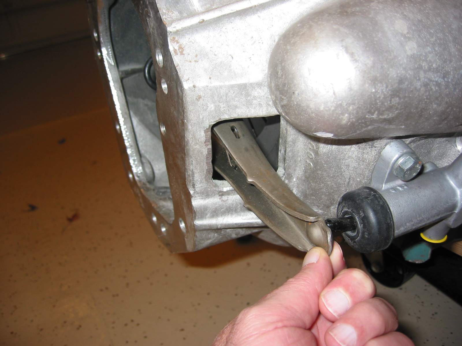
The proper positioning of the two hinges or “triggers” is important. They have angles on the end that fit opposite each other. They need to be placed as seen in the image and drawing for the canceling switch to work. Before reassembly of the complete unit, now is a good time to refinish the bakelite if it is needed.

Trafficator Rebuild Image 14
Refinishing the Bakelite Head
I have lost the source of these instructions or I would give attribution, but clean the head well and wipe with a liquid cleaner like the type used before spray painting metal. Then apply black India ink. I used two coats letting the first coat dry for about an hour before applying the second. Then use black paste shoe polish rubbed in well. Polish. Reapply paste and polish again. Finally, apply a coat of carnuba wax for protection and final shine. Be very careful to not drop the bakelite head! I recommend doing all the polishing over a carpeted floor in case the head is dropped. This should result in a control head that looks brand new.

Trafficator Rebuild Image 15
Assembly
Carefully place the head and the mounting plate together pushing the spring at the end of the turn signal lever into the mounting plate. Holding the two pieces together install and tighten the single screw and nut at the bottom of the unit. This screw/nut will securely hold the two pieces together while the horn switch screws and nuts are inserted and tightened.

Trafficator Rebuild Image 16
I recommend, based on the comments of others and my own experience, cutting the bullet connectors off the wires, solder the wire or tie the fishing line left in the steering column, to the new wires and slowly pull the new wiring harness through the stator tube and out the end of the steering box. The fit of the harness in the tube is tight so it might be best to tape the wire ends together as they are pulled through.
Steve Byers took a slightly different approach that certainly makes taking the wiring through the stator tube easier. He commented, “although I have been able to pull the harness out of the column with the connectors installed, I have never been able to put it back in no matter how tightly I taped/wrapped the connectors together. The last time I did this, I installed a new steering column harness as a part of a general re-wiring. To make it easy on myself, I cut off all the bullets from the new harness (leaving about 3/4″ of the wire attached to each), fed the harness through, and then soldered the bullets back on with a piece of heat-shrink tubing over the splice. The key is, I did not twist the wires together before soldering but soldered them together as they lay side by side. That way, next time the harness needs removing it will be easy to remove the bullets without damaging the wire, and that can be done many times without damage to the wires.”
The short stator tube fits down and into the longer stator tube in the column. The tubes go together in only one orientation, directed by the dimples found on the side of the short tube.
If you are installing the control head into a non-stock wooden steering wheel (Moto Lita, Derrington) you may need to install a shim (I used the plastic top of a yogurt container) inside the hub between the hub and the control head to move the control head toward the driver slightly so that the turn signal lever does not contact the wheel ring. Then reinstall the three set screws to tighten the control head to the wheel hub. The job is complete! Now the control head (horn and turn signal control switch) will look and work as well as the rest of your car.
Roger Moment’s tips for installing a new steering wheel or repairing the trafficator without removing the wiring.
For those who are really bold and experienced Roger Moment has informed me that it is possible to complete a trafficator repair or replace a steering wheel without having to pull the wires up through the stator tube. I have no personal experience with this approach so I cannot comment on the degree of difficulty, but if Roger says it can be done, then it can! However, he emphasized that it should only be attempted by those who are totally familiar with the disassembly of these units.
The relevant steps are:
Unclip the end of the steering column harness so that there is about 8″ or more of slack. This is accomplished by locating the clip that holds it to the cross brace in front of the radiator.
Back off the three retaining pointed screws in the steering wheel hub.
Pull out the head enough so that it can drop down across the front of the steering wheel.
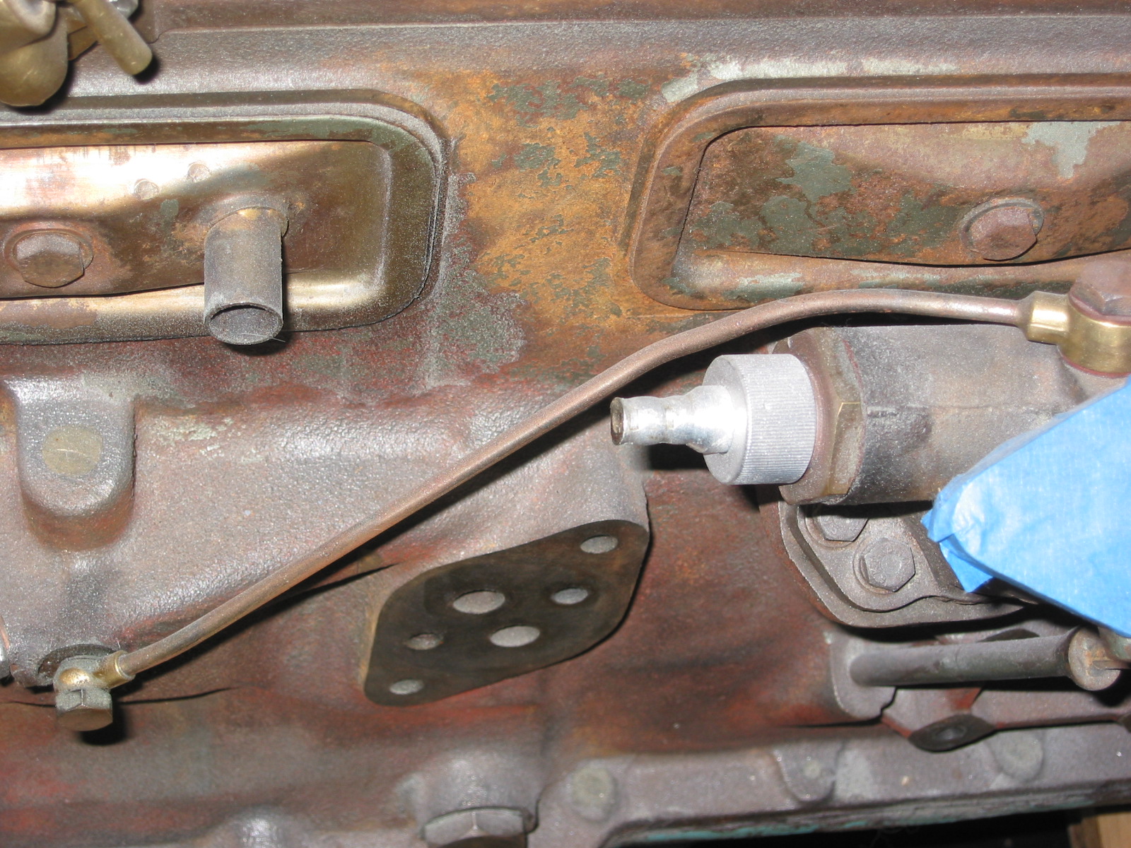
Push up and rotate the retaining tab as seen in Image #3 and below in Image 17.

Trafficator Rebuild Image 17
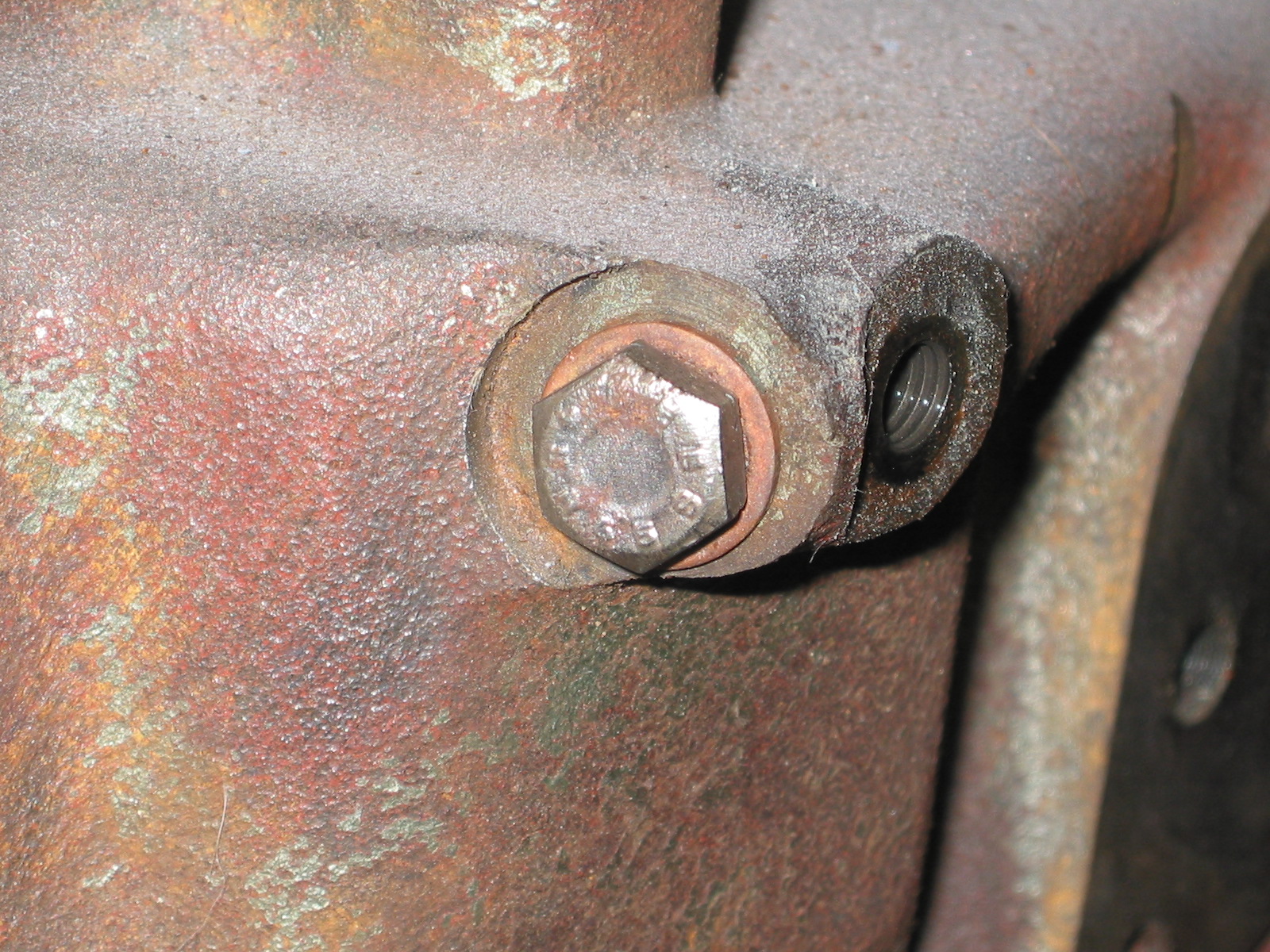
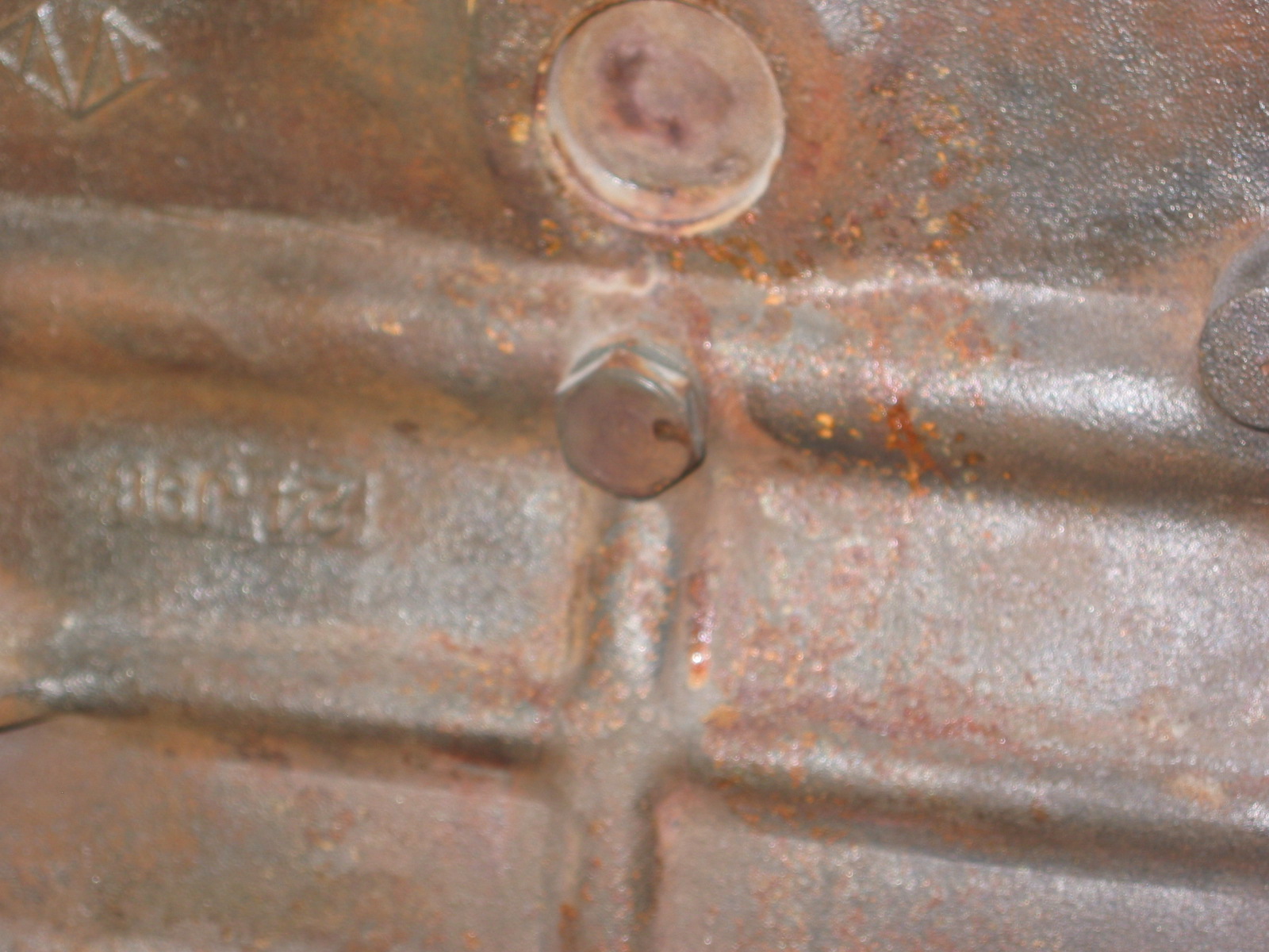
Remove the three screws securing the mounting to the backing plate.

Trafficator Rebuild Image 18
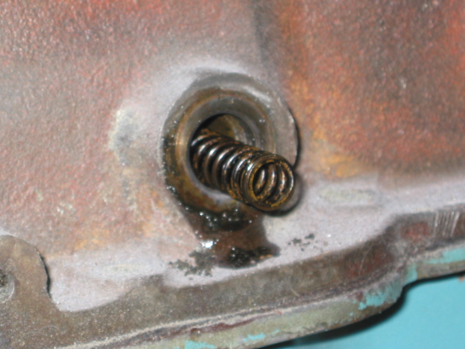
Then separate the backing plate:

Trafficator Rebuild Image 19
One can then remove the wires as described earlier in this article, using the technique with the lever to “back up” the contacts so that they don’t fall into the head. It is very important to replace the nuts immediately after removing each wire!
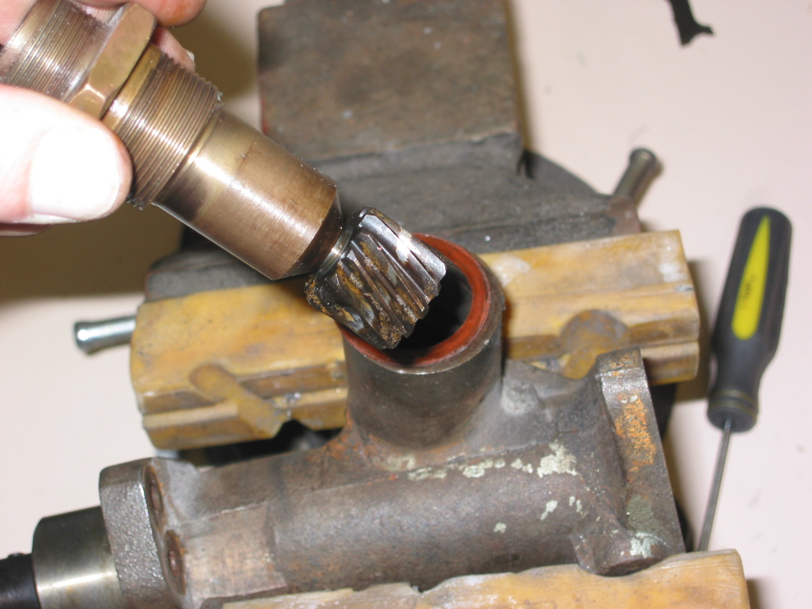
Once the wiring has been removed from the switch assembly, if you are only going to repair it you can leave the wire loom in place in the short sliding part of the stator tube. However, if you are planning on removing the steering wheel to replace it, you must first draw the wires back through the short tube. This is easily done by first folding only twoof the eyelets tightly back against the wires, leaving the other two extending straight. This creates a “package” that is compact enough to slide through the tube. Next remove the circlip and pull the steering wheel off the shaft.

Trafficator Rebuild Image 20
Roger indicates that this “in-car” method will also work on non-adjustable steering set-ups (on 100s and those few 6-cylinder cars that are equipped as such). However, here the entire stator is drawn up after loosening the clamping nut. The steering box oil will drip out around the wires at the end during the time that the tube is partially withdrawn. As soon as the wires are freed, the tube can be re-inserted and the nut re-tightened. You’ll only lose a bit of the oil and it still beats reinserting the entire tube.
Roger suggests that if you do draw out the tube, use a 3/8″ bolt with a good 1″ or so of smooth shank to re-insert into the nut and olive at the steering box to keep most of the oil from draining out. This bolt is then removed when the tube and wires are put back through.
Happy Healeying and Cheers!
Lin Rose
1960 BT7
1959 Bugeye
July 7, 2005
Revised October 2, 2005
Click this link for a pdf of the trafficator rebuild: Trafficator Repairs Low Res
This entry was posted on Tuesday, July 17th, 2012 at 4:15 pm. It is filed under Big Healey, Steering/Trafficator and tagged with Control Head, Roger Moment, Steering, Steering Hub, Tafficator