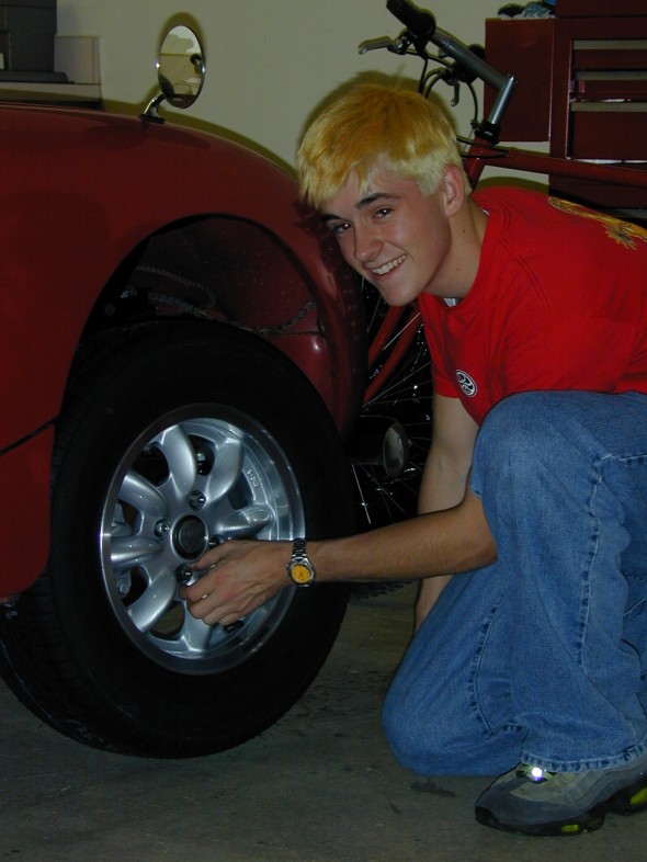
I ordered new Panasport 13 x 5″ wheels. I paid for the wheels and Dad paid for the tires – 185 x 13 70 Bridgestones. The tire selection turned out to be a mistake, they were too big and rubbed the bonnet when the wheel turned.
We ended up replacing the Bridgestones with Wynstar 185 x 13 60 lower profile tires which worked fine. Unbelievable difference in the handling for the car – it really sticks to the road now. Needed to order new lug nuts for the Panasport wheels as original equipment didn’t work with the wheels.
Hayden Electric Fan
Installed a 10″ electric fan to replace the plastic stock fan. Required fabricating some metal brackets to mount the fan, rather than using the plastic mounting screws provided with the fan. It’s better to have the fan pull rather than push air, but that won’t work with the bugeye because the fan won’t fit on the engine side of the radiator. Installed the fan with an on-off switch at the dash but will replace it with an automatic thermostat to control fan operation.
Intake Manifold
Located a used stock intake manifold. Installed it and eliminated the problem with the carbs hitting the bonnet when closed.
Conversion to Front Tilt Bonnet
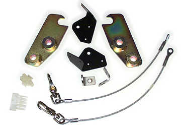
Purchased a front hinge kit from Minimania. Good kit that included complete instructions, hinges, cable restraints, brackets (although the cables were too short), and wiring. Removed original back body hinges, and latching mechanism at the front of the bonnet.Mini Mania FRONT- MOUNT HINGE KIT FOR BUGEYE SPRITE
- Clip headlight wire harness 16″ from passenger side blinker.
- Remove bonnet
- Remove telescopic bonnet catches
- Remove grill (13 retaining clips)
- Remove bonnet handle
- Remove two locating pins for bonnet
- Install support cable bonnet securing plates – 2 to bonnet installed by pop rivets and 2 on radiator mounting brackets
- Remove bonnet hinges – a long bolt and nut reached under the dash.
- Remove bonnet safety catch/latch
- Remove latch locator plate
- Install stainless steel bolts for new bonnet securing springs.
Fabricated hold-down spring brackets using a conduit clip, spring and stainless steel bolts. This approach, copied from John Carey’s web site works great and is much less visible than rubber or leather straps on the side of the body. The front hinge set-up does not permit use of the front bumper. This assembly is made from a galvanized conduit wall clip slightly bent closed and attached to a zinc plated spring. It is covered with a black plastic wiring harness cover so as not to be too obvious in the dark wheel well. The small stainless bolt is installed thru an existing hole in the bonnet (top of spring – left).
You must use nuts on both inner and outer sides of the bonnet to hold it firm in the position shown. You can crank the wheels out of the way and quickly clasp the conduit clip under the floorpan lip (lower at left) then stretch the spring up until it grabs the head of the stainless bolt. The position is perfect to hold the bonnet down and in against it’s intended rubber stops… This eliminates drilling to install and works great even in HEAVY cornering and bumping along back country roads. It is also as quick or quicker than leather buckles to open and close.
Conversion from Dynamo to Alternator
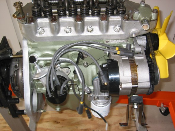
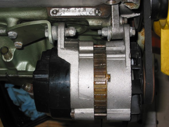
Removed the dynamo and installed a lucas alternator. Required reworking wiring and eliminated the need for the voltage control box. Referred to directions from Larry Miller and John Carey for wiring help. Seems to work well and should be a bonus if we ever add driving lights, halogens, radio and etc. A new fan belt was required for the alternator that is shorter than the belt used for the dynamo.
Removed and discarded large yellow wire from terminal D on the voltage regulator box to the dynamo. It is no longer needed.
Removed black ground wire from terminal E on the voltage regulator box to the dynamo. It is no longer needed.
Removed black wire from terminal F on the voltage regulator box to the dynamo. It is no longer needed.
Connect brown wire from alternator (middle spade) to battery post terminal.
Connect small yellow wire from speedometer warning light that originally went to terminal D on the voltage regulator box to the small spade on the alternator.
Connect large yellow wire from ignition switch that originally went to the A1 terminal on the voltage regulator box to the baby blue wire to the remaining large spade on the alternator, and to the purple wire from the fuse panel. These 3 wires are soldered together.
Collect wires and plug connector into the alternator.


