Rather than using the original Smiths heater, I am taking advantage of more modern technology and substituting a two speed heater available from Cape International. The heater unit integrates the hot water radiator as well as the fan blower. I had installed the heater unit previously and the time had come to put the demister hoses in place. These install basically as on the original.
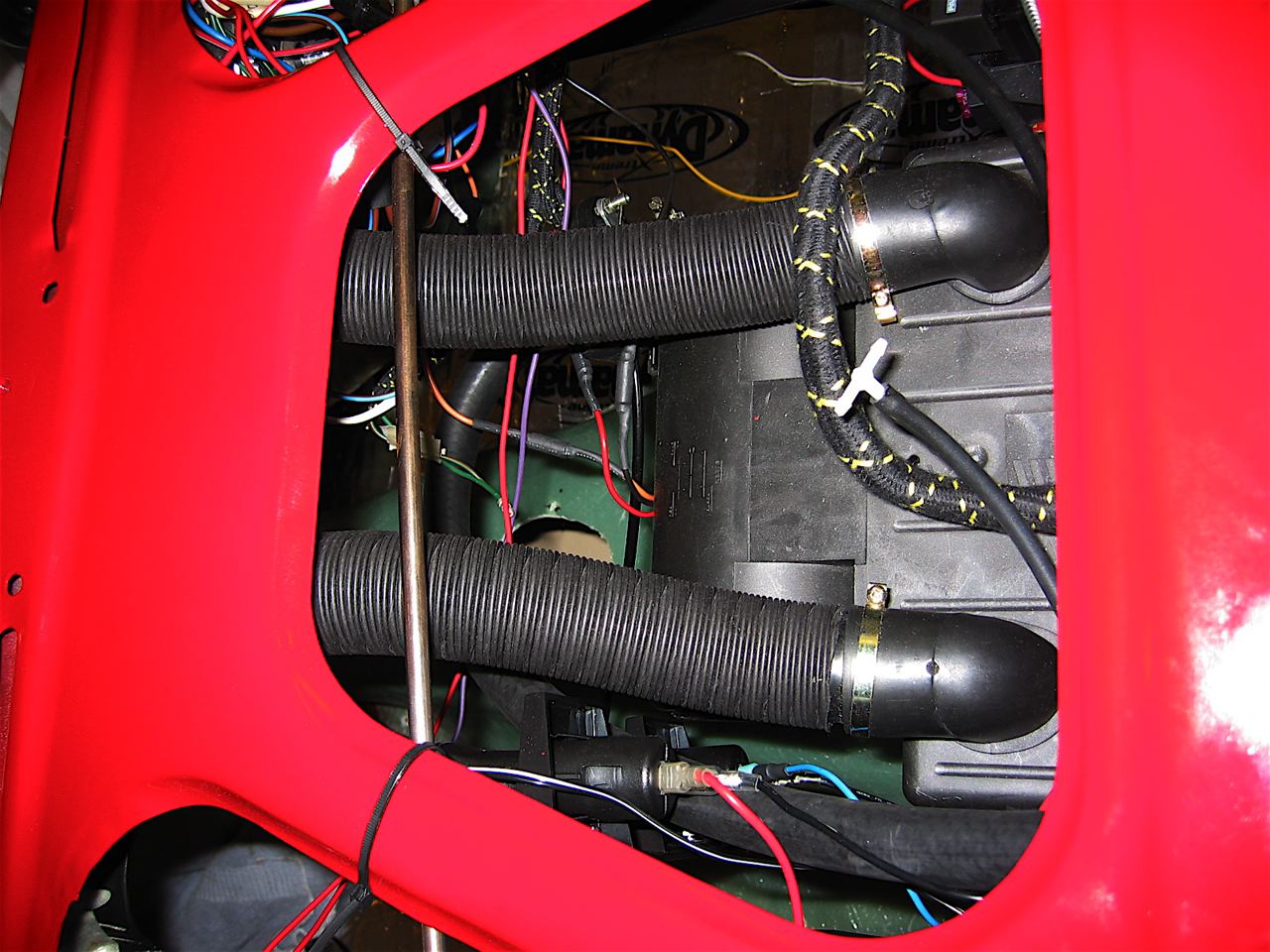
Demister hoses
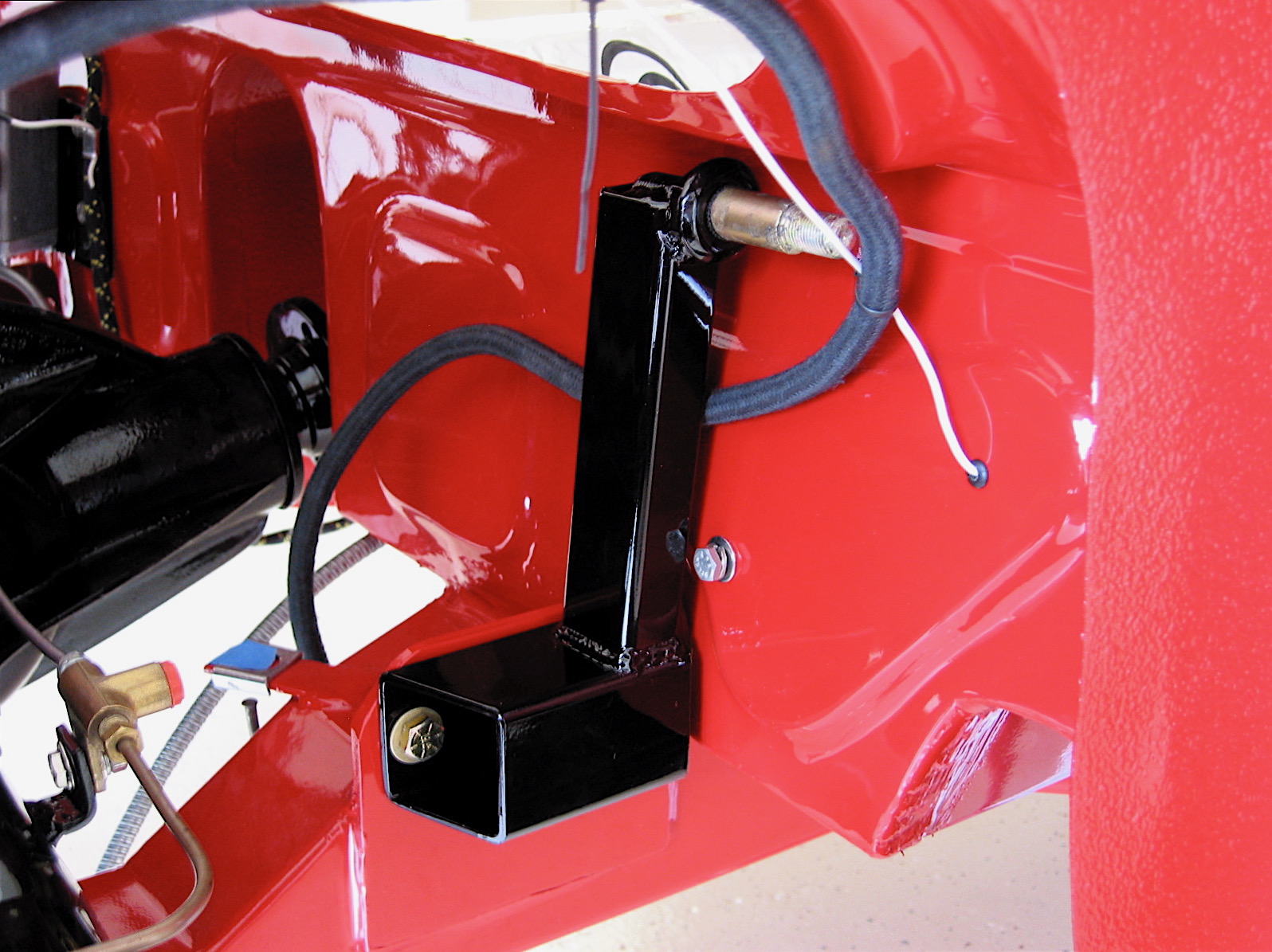
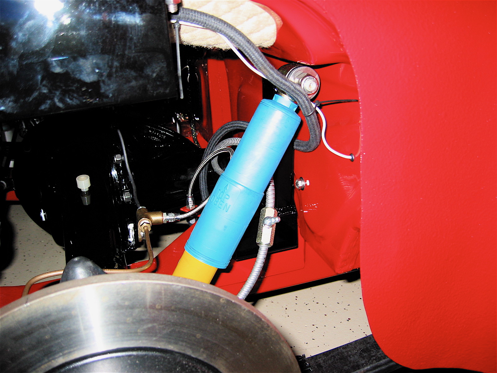
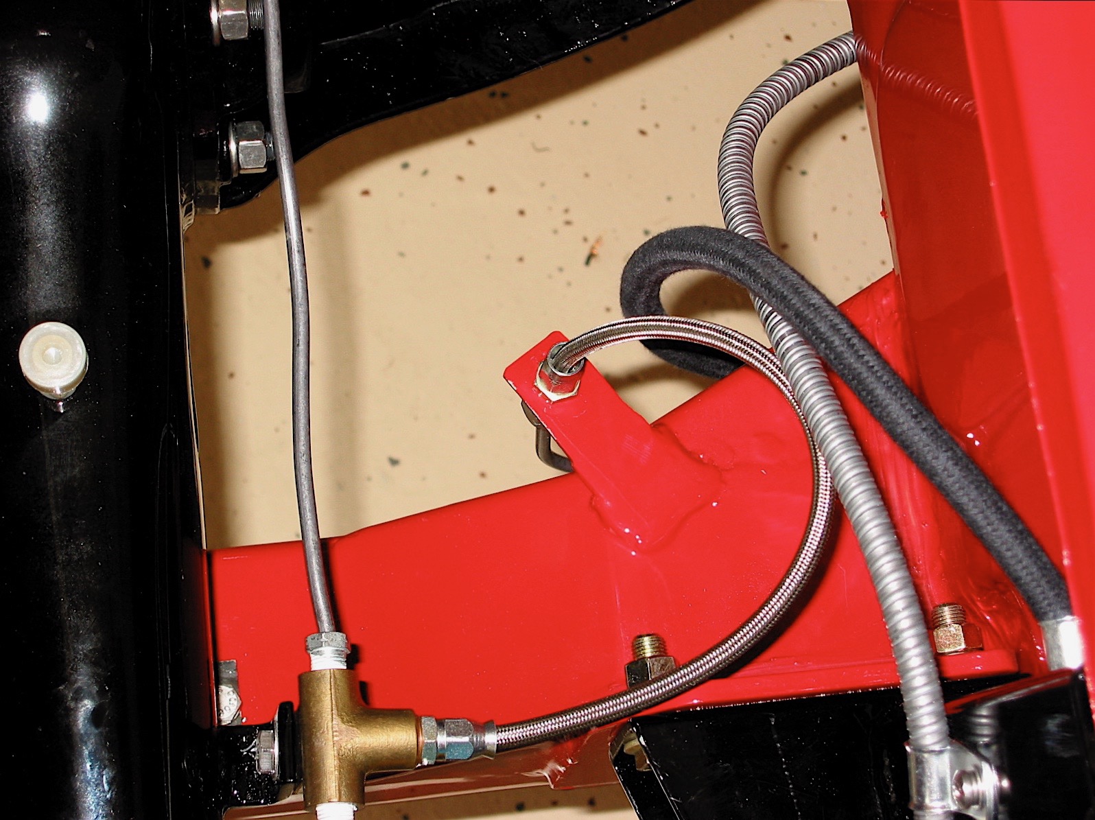
The next task was to install the hot water heater hoses. The kit is supplied with brass step down joints as the interior diameter of the hose at the heater and at the control valve is larger than the hose that connects to the heater control tap on the motor and the water return pipe.
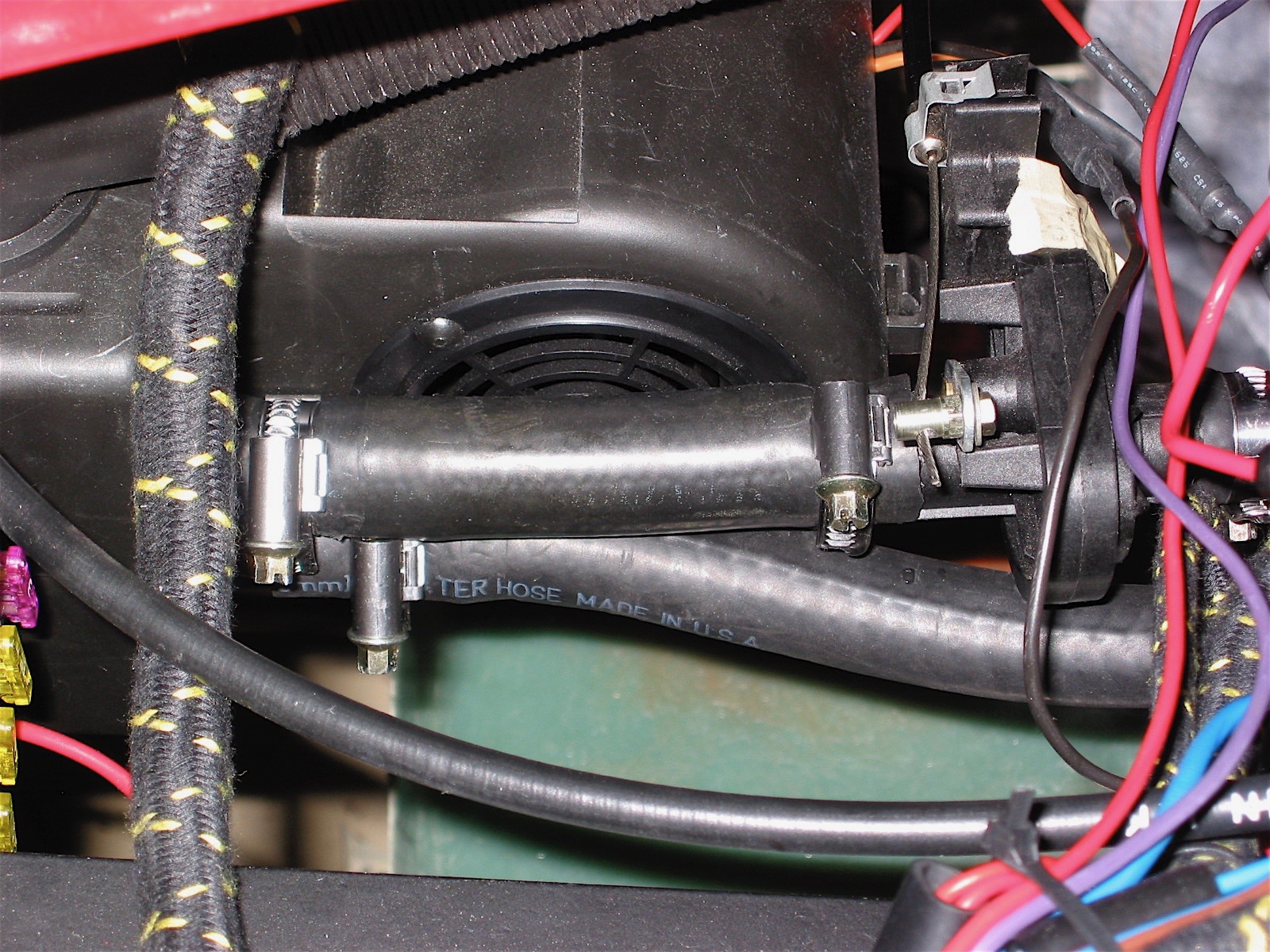
Heater hoses Step-down

Heater hoses Step-down
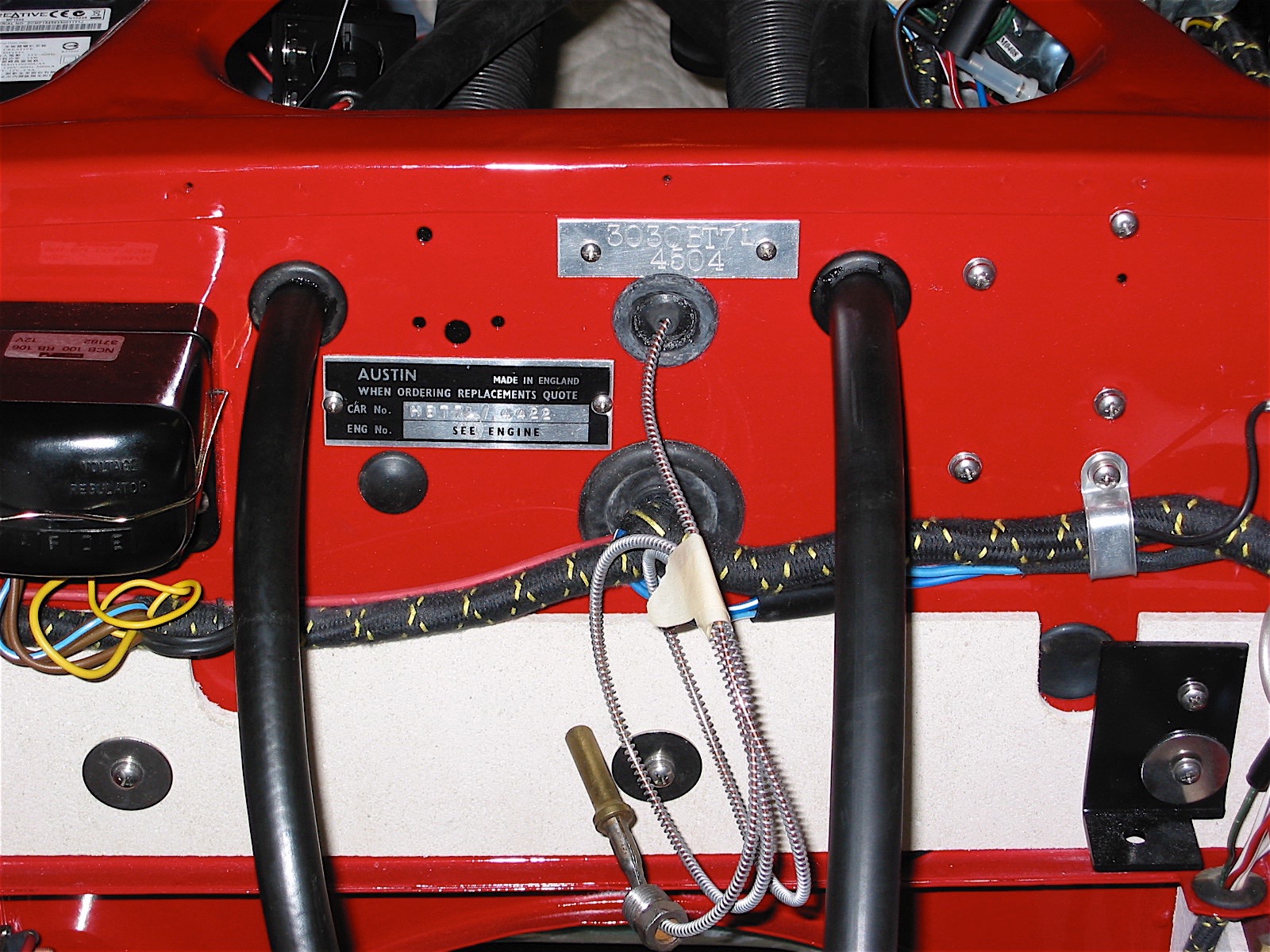
Heater hoses through Firewall
The wiring for the ground connection and the power to the two fan speeds is sadly visually obvious from the interior seating. To obscure the wiring a bit, I ran all three wires through a length of heat shrink tubing.
Then the Cape heater water control valve was connected to the original heater control panel by a short length of bicycle derailler cable. Since I am using the overdrive switch to control the two speed heater fan, the switch on the heater control panel is available to control the original Smiths blower to bring fresh air into the passenger seating area. Whether the new heater works any better than the Smiths unit, I don’t know. We will see come next winter!
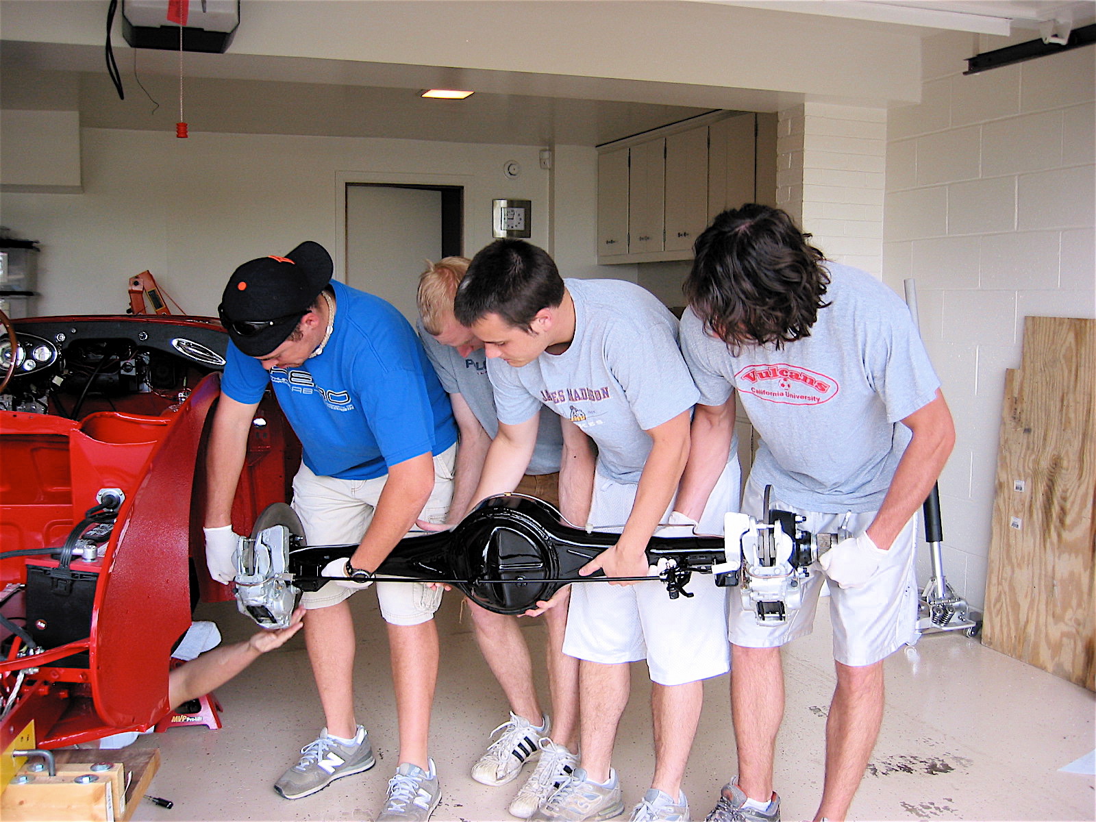
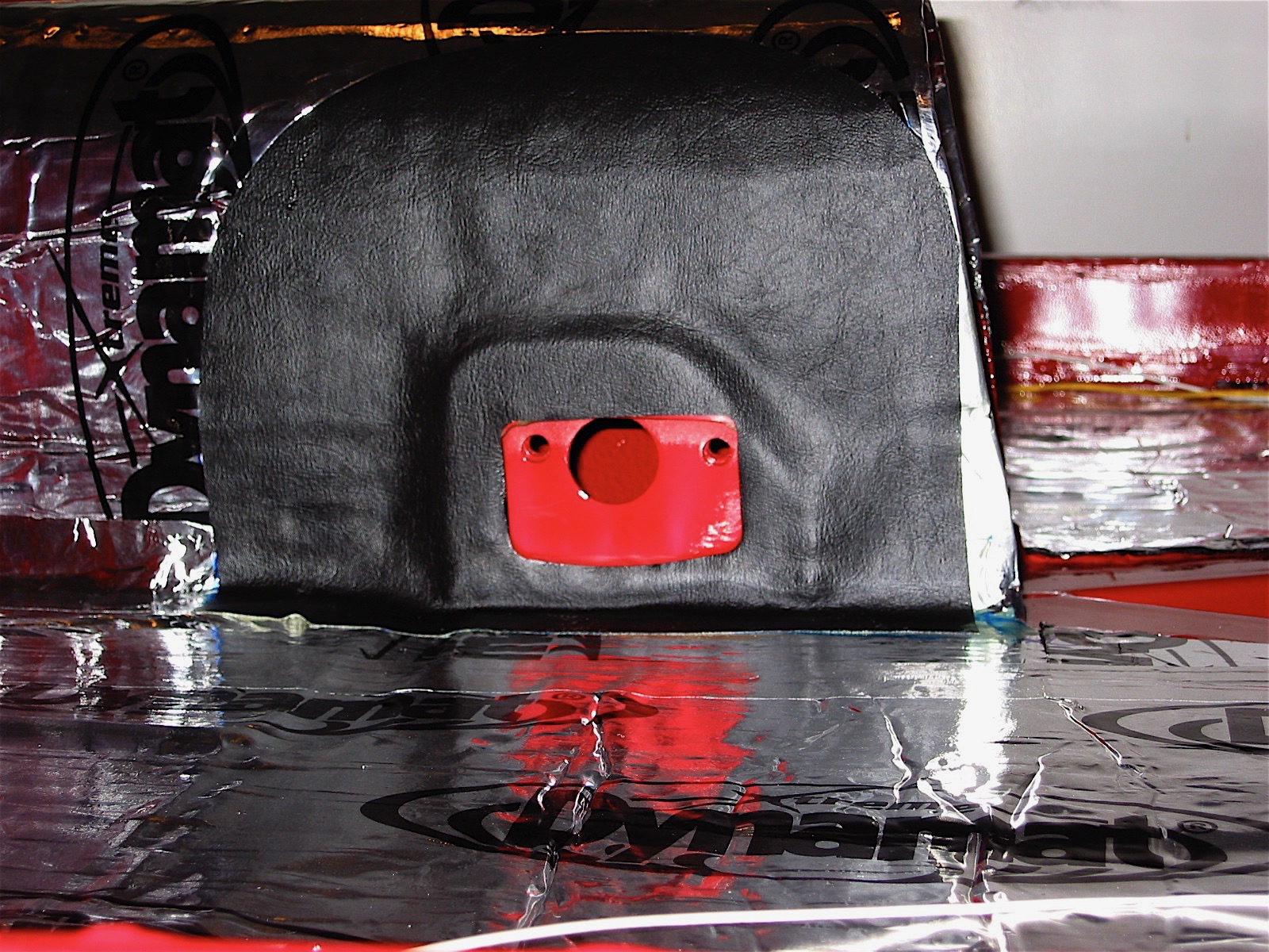
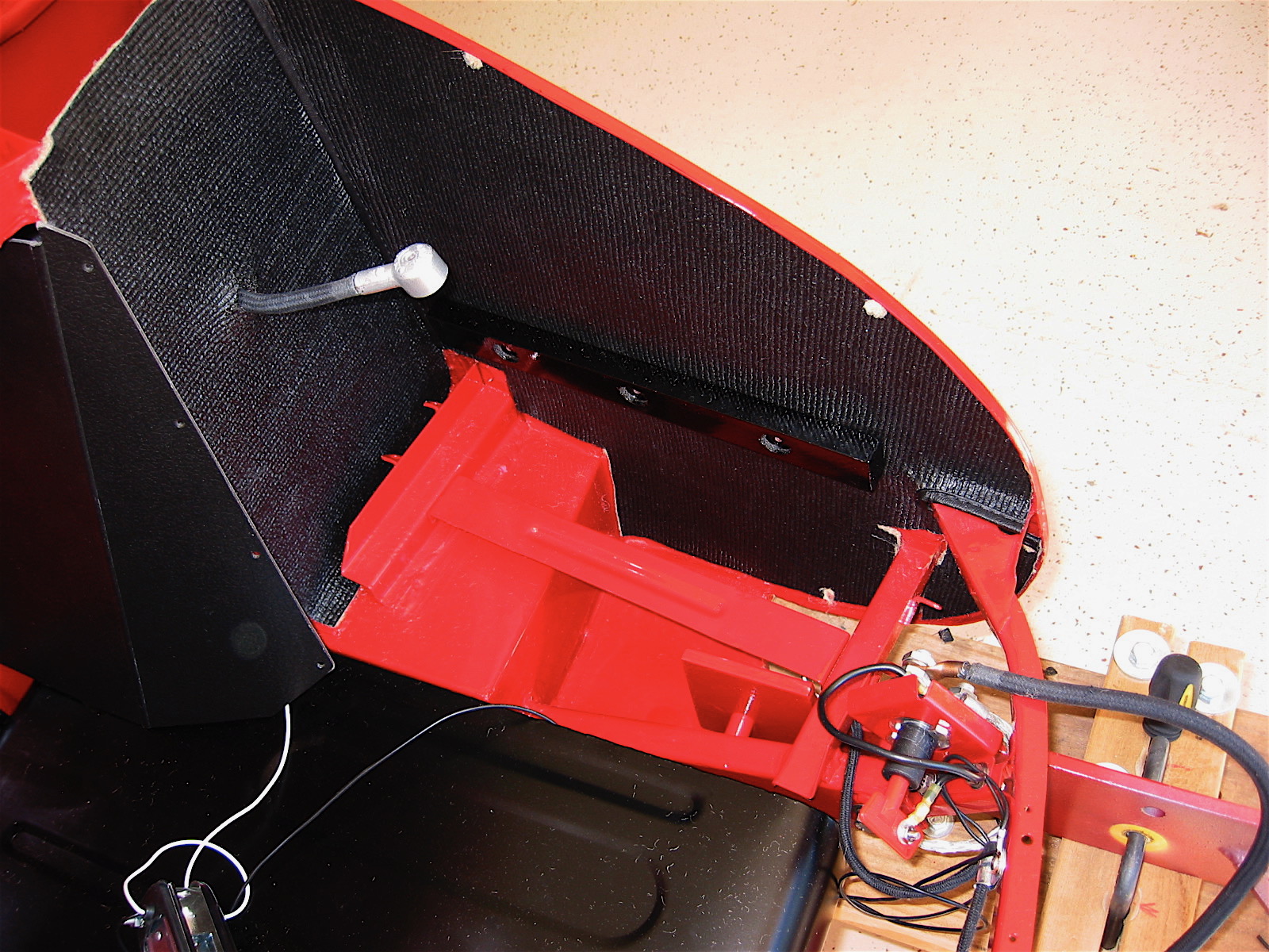
It was now time to move to the boot to install the Armacord and fuel tank. I ordered my Armacord kit from Heritage Upholstery. I began with the vertical piece through which the battery cable runs and then moved to the right and left pieces that fit the rear inner quarter panels. I brushed on Weldwood contact cement for the adhesive on the body components and used 3M spray adhesive for the back side of the Armacord.
Boot Armacord 2
Boot Armacord 5
The left rear wheel arch was difficult to cover without some minor buckling. I was not entirely satisfied, but in this case, my less than perfect fitting will be covered by the spare tire.
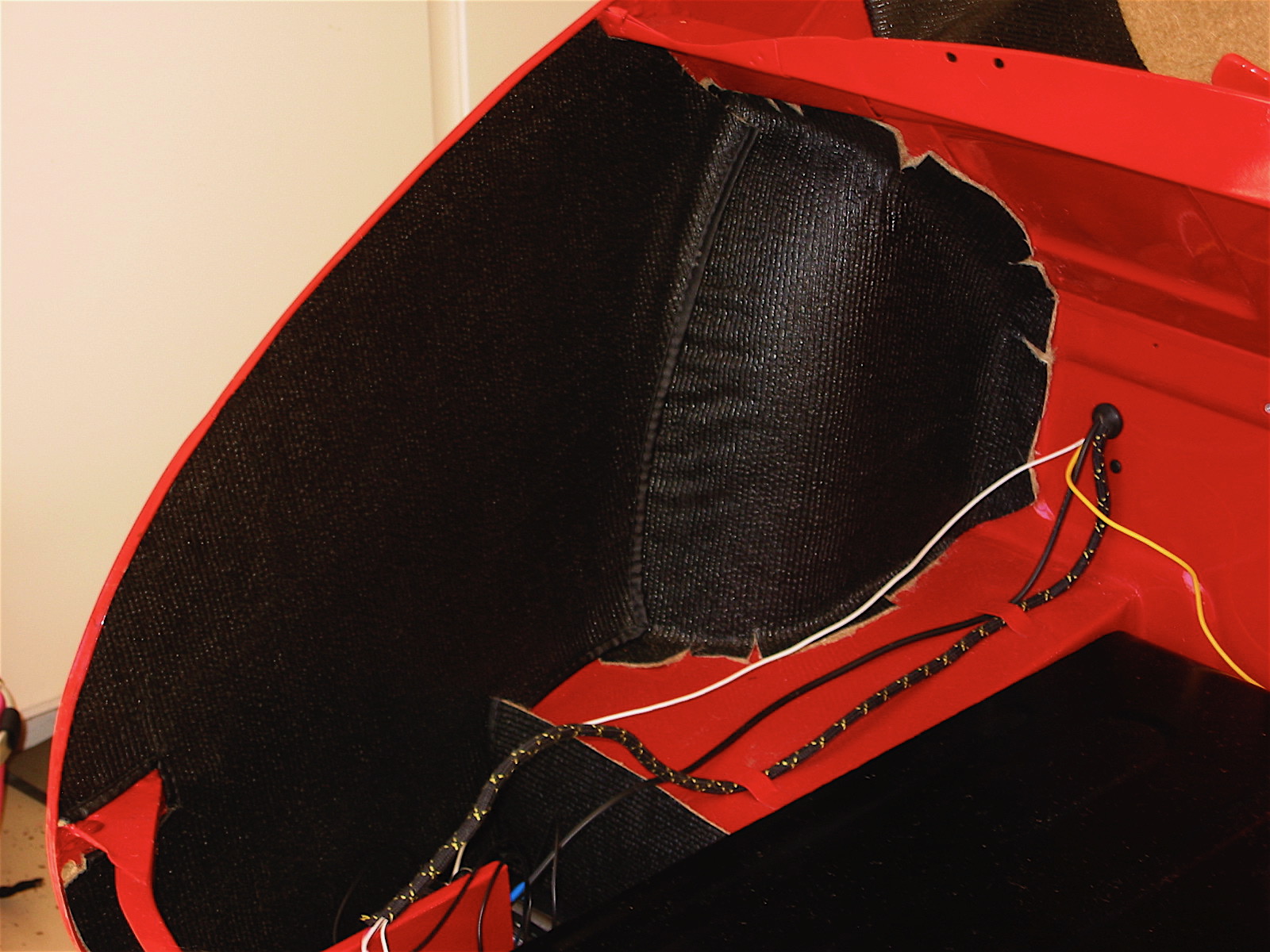
Boot Armacord 6
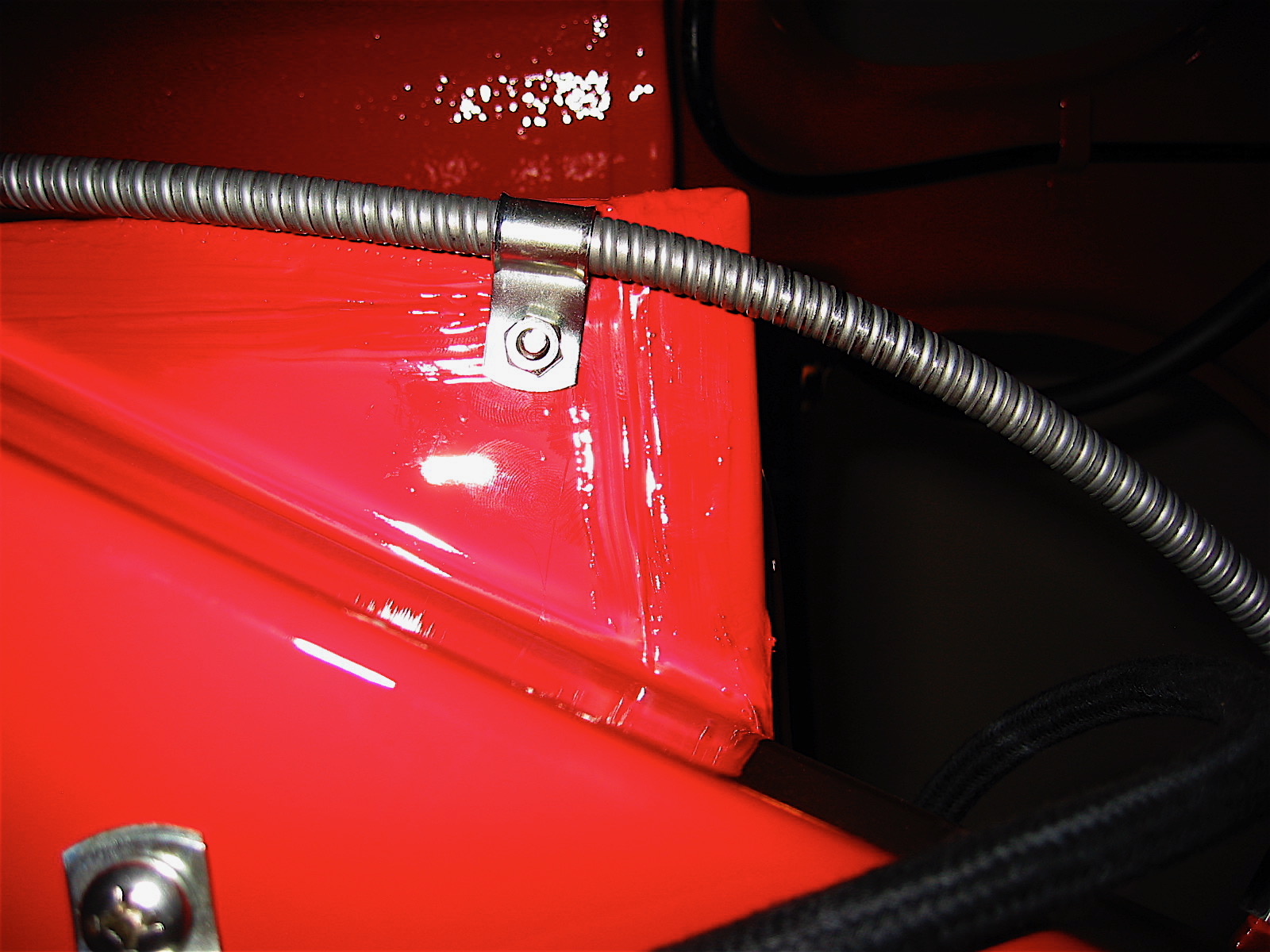
I then installed the vertical rear Armacord panel. In addition to gluing this piece in place I installed three pop rivets as original. I also installed three #8 stainless self-tapping screws and trim cups through the Armacord and into the rear bulkhead wall.
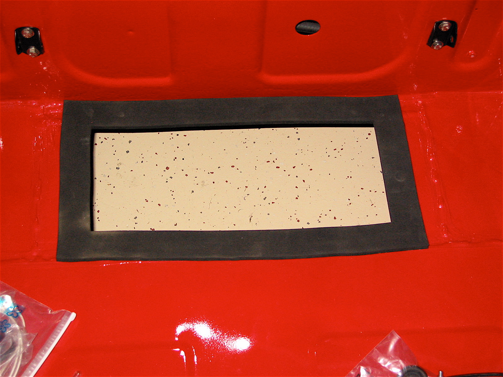
The two spare tire wood blocks and tie down hardware were then installed. I am using Michelin ZX 175 tires that required repositioning of the left quarter panel block, raising it about 1/2.” I made a new longer and thinner wooden block for the rear bulkhead so that I could continue to use the original mounting holes.
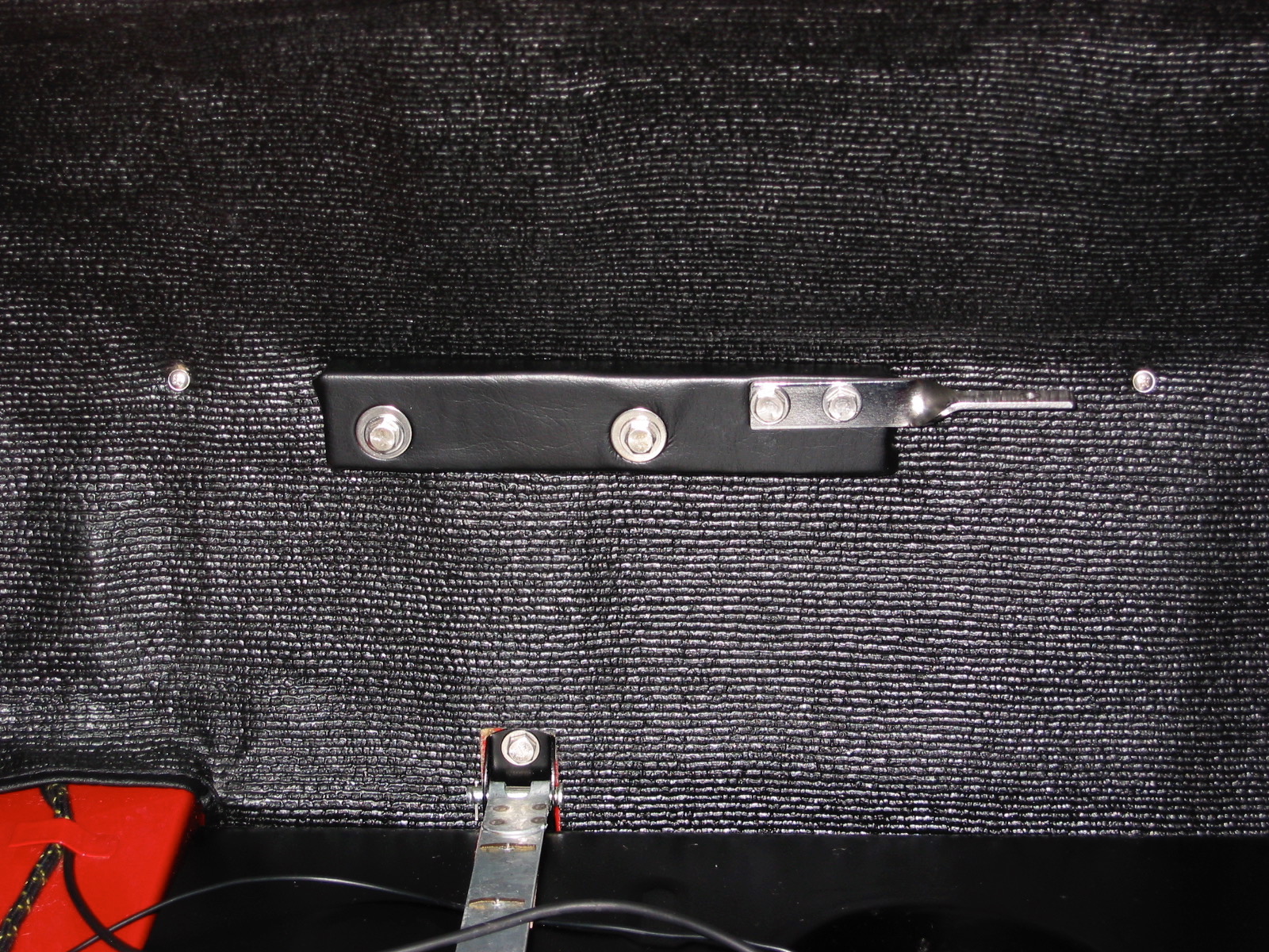
Armacord rear bulkhead
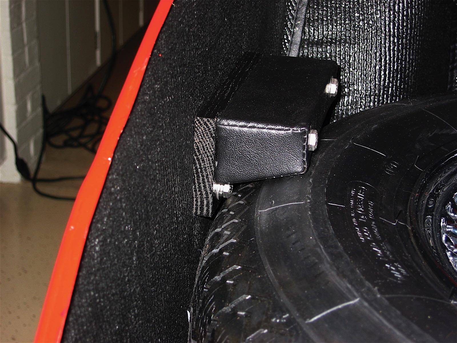
Spare Tire Stop Extension