Chapter 54 Restoration Assembly, Week Twenty-Four 5/28/2007

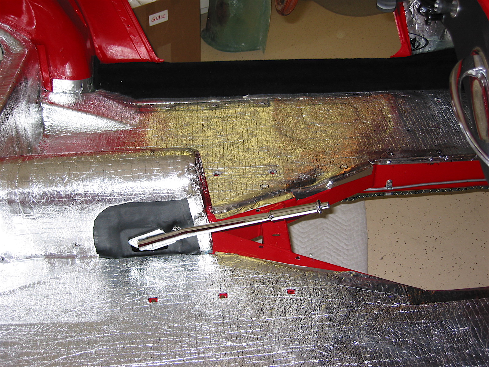
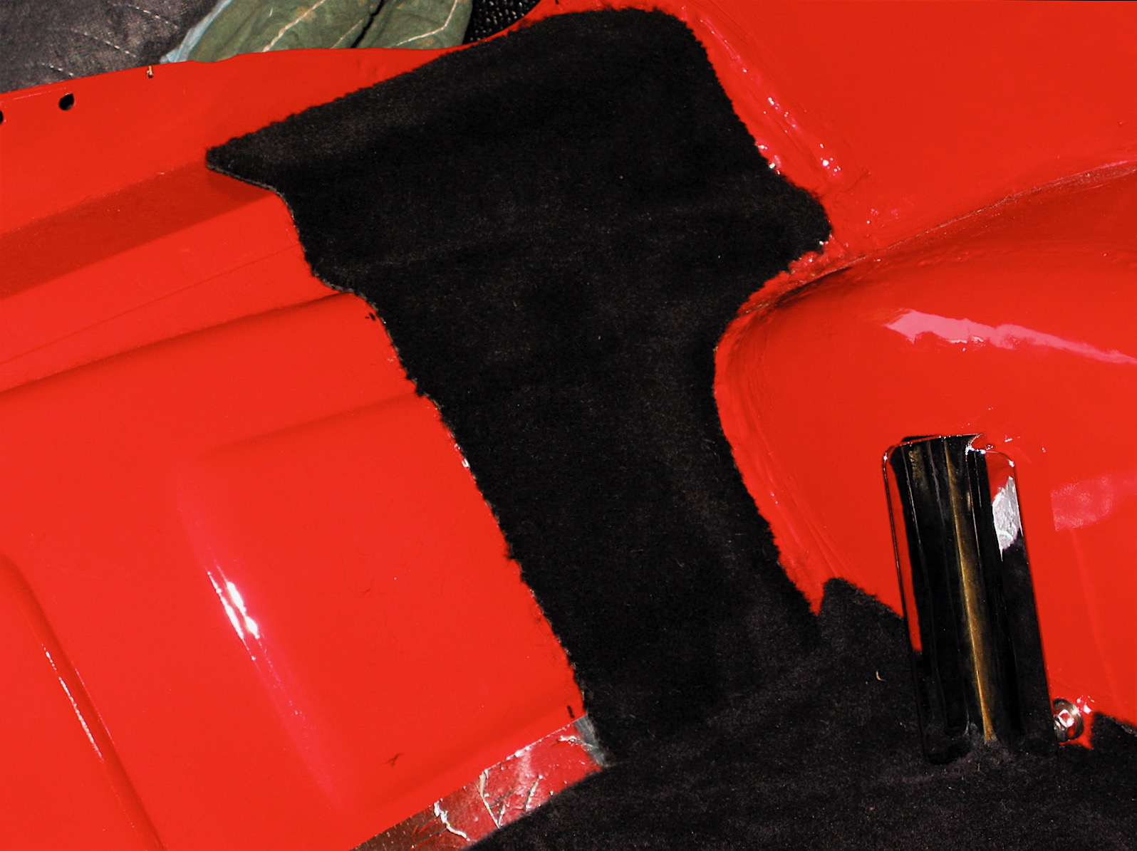
After the LH side rail was carpeted I installed the carpet piece for the driver’s side footbox toeboard. This was the most difficult piece to glue in to the car because it is a little harder to get to (as in standing on your head!) and because it is one piece for two panels. It also incorporates the vertical panel by the gearbox surround. After several iterations of fitting I was pleased with the result and glued it in place. Then on to the RH side.

RH footbox carpet

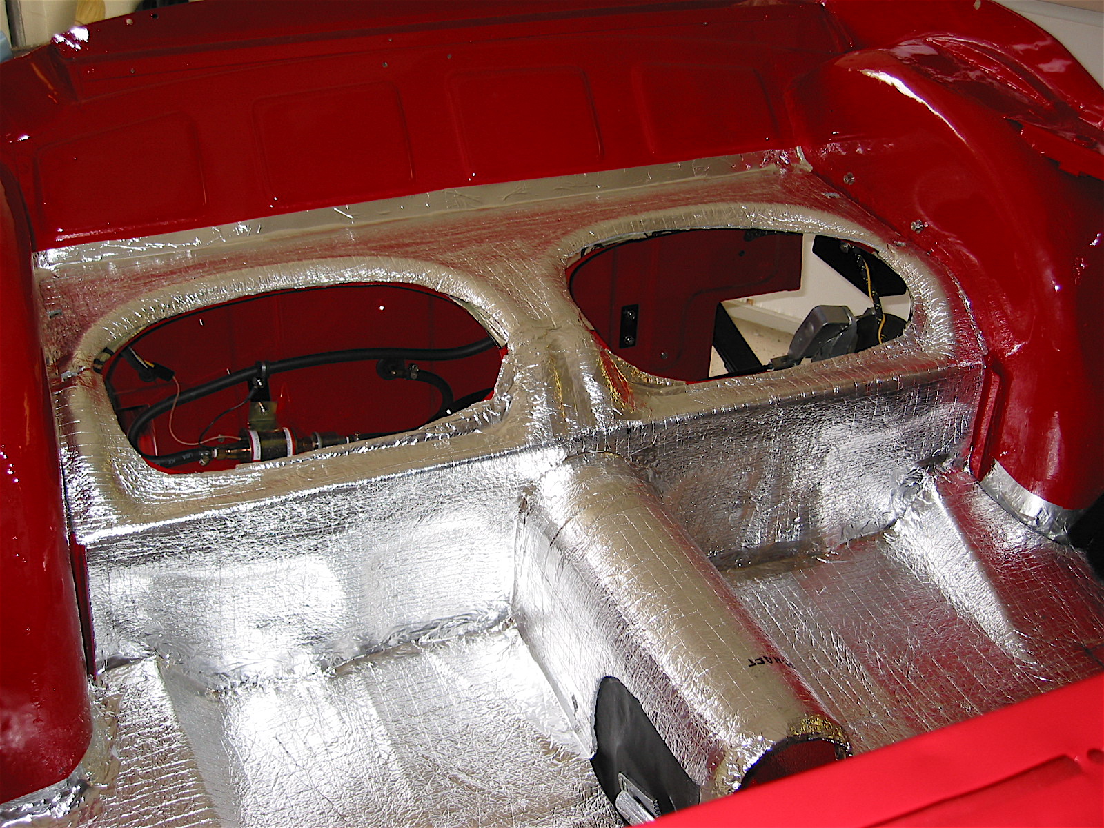
Next came the two pieces of carpet that are glued to the vertical kickboard bulkhead behind the front seats and the rear seat surround. With some minor trimming they fit nicely. I then glued the two small pieces to the LH and RH side of the rear of the car where the soft top and its frame rests when folded down.

RH rear panel carpet

LH rear panel carpet
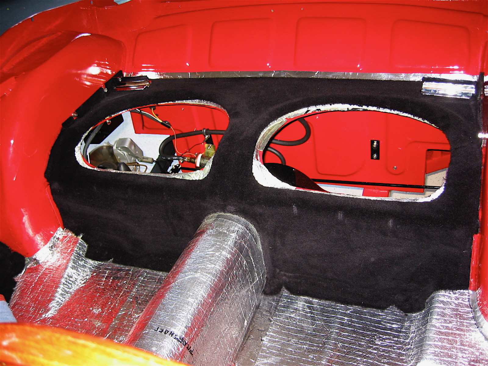
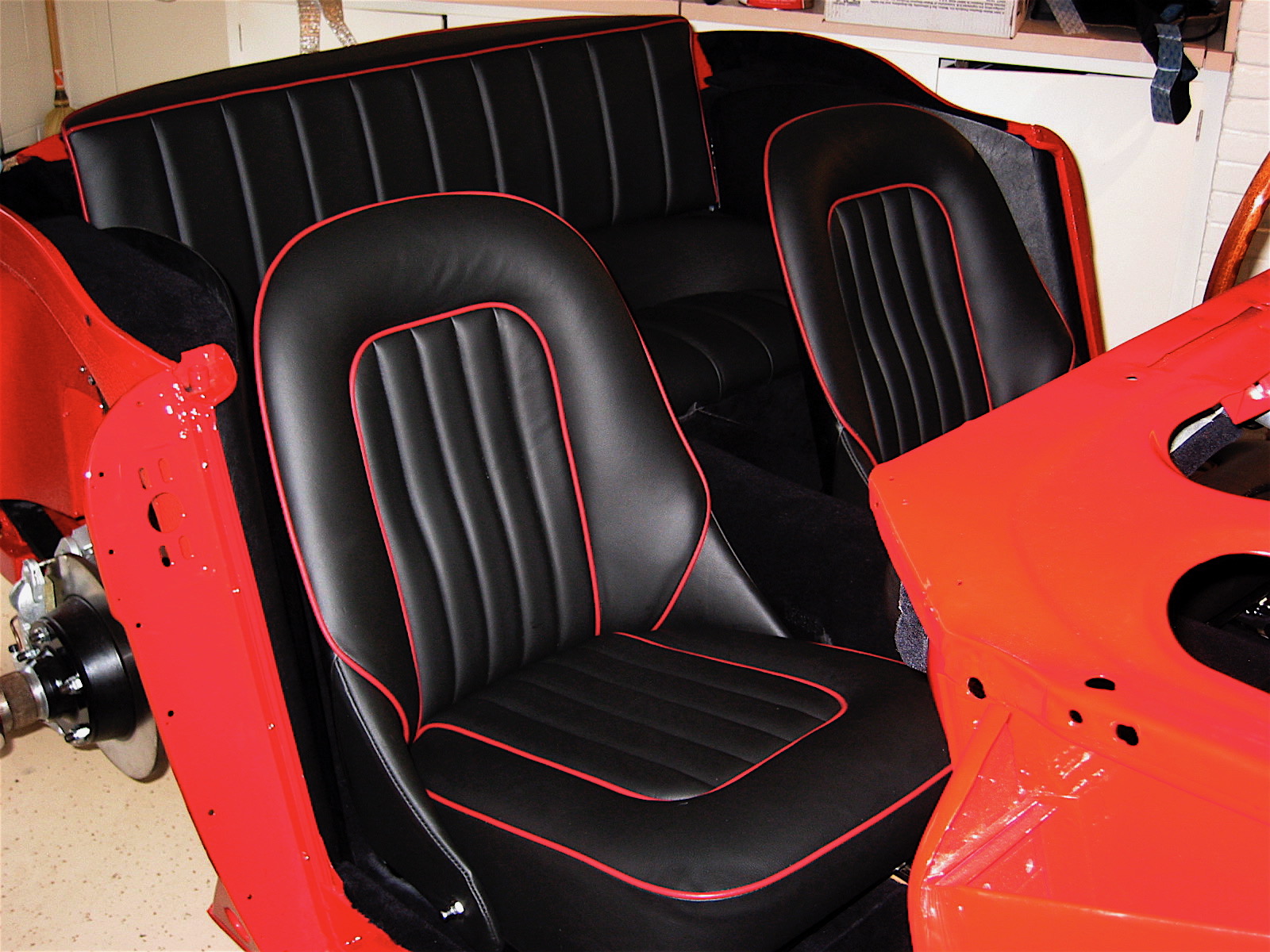
Rear seat carpet

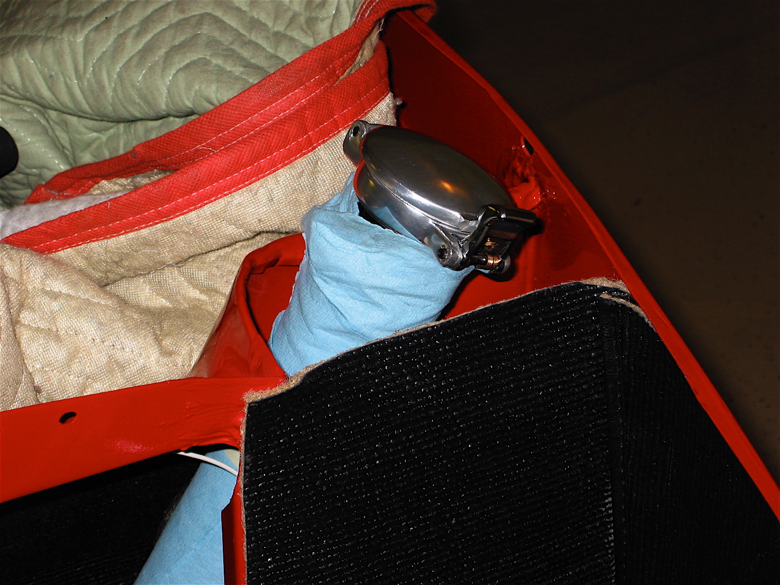
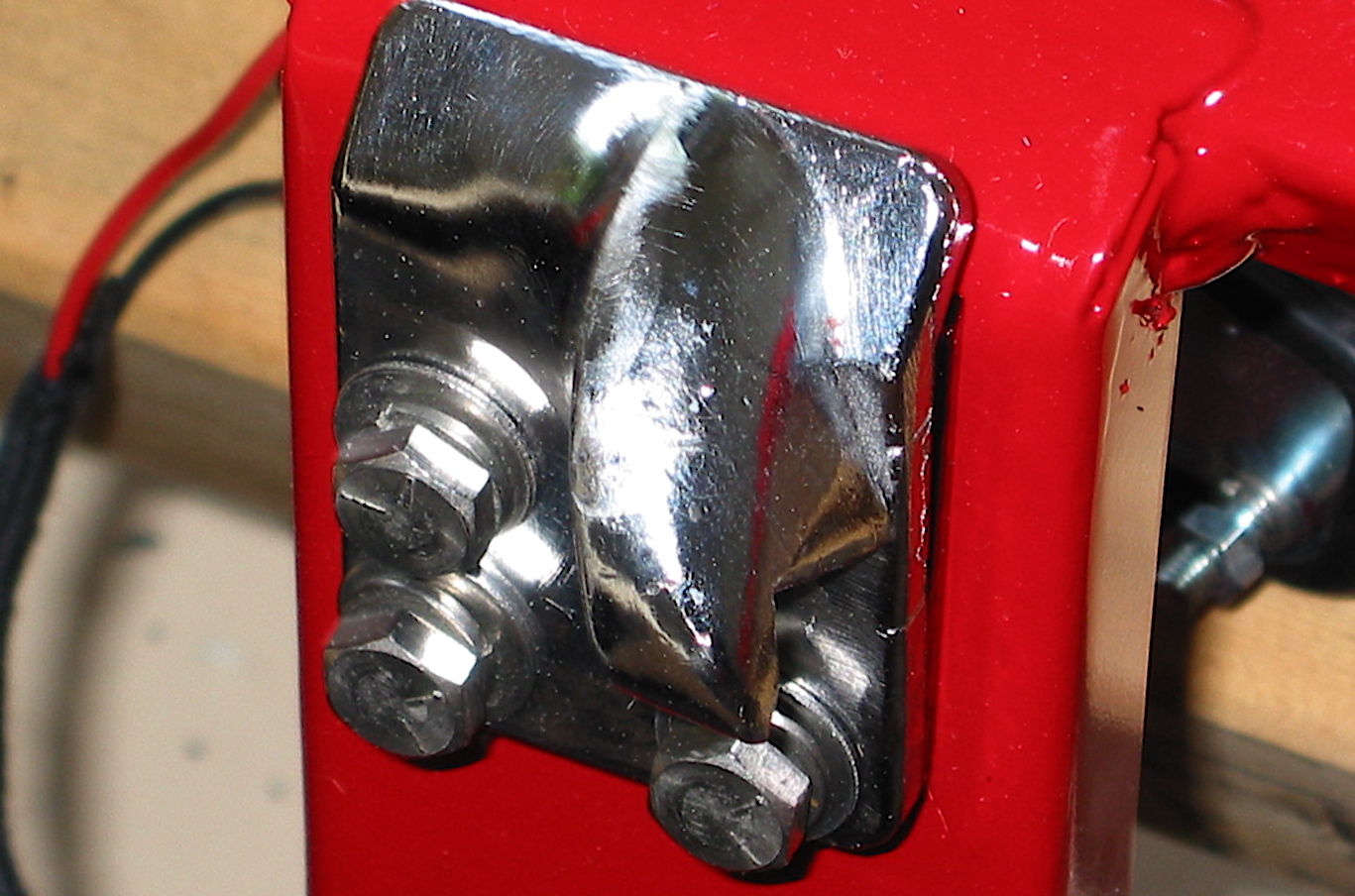
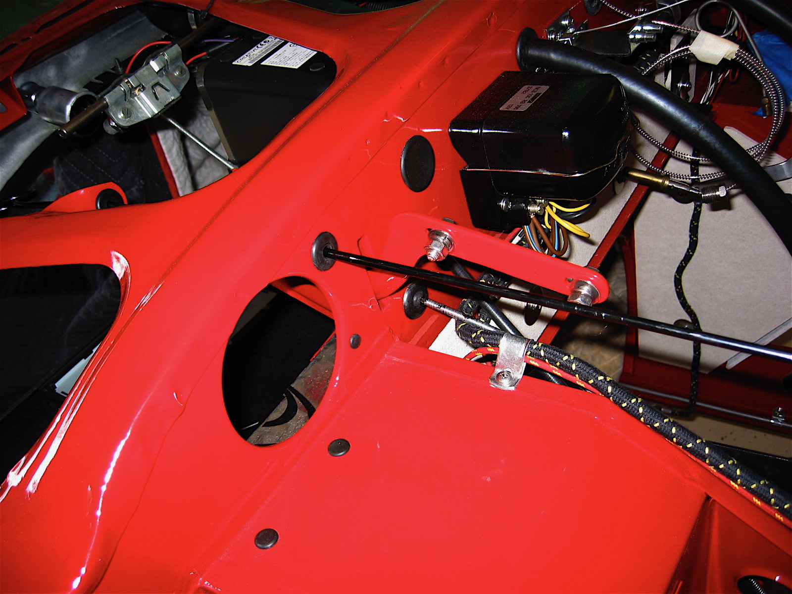
The hardware for the rear vertical upholstered panel was then mounted to the car and the panel was dropped into its position.

Rear seats

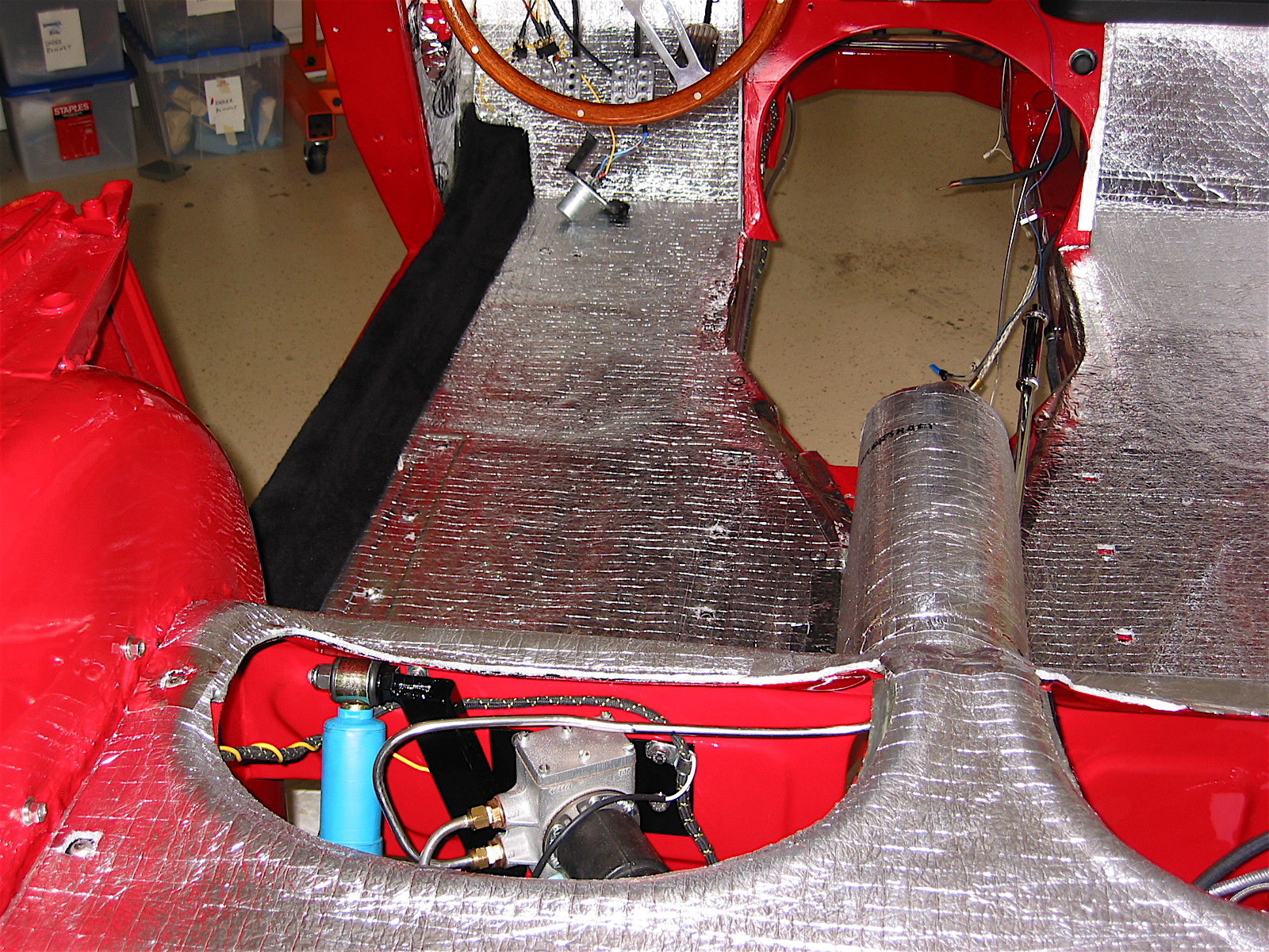
 The RH side rail carpet was glued to the rail as per the left side installation.

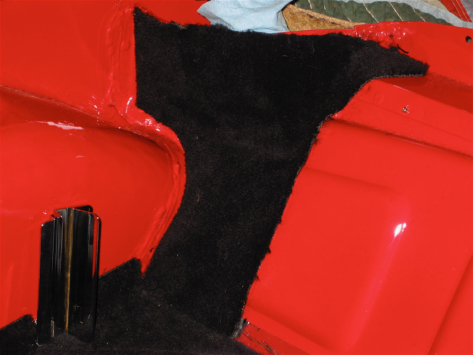
Heritage Upholstery and Trim provides a piece of vinyl (as per original) to cover the RH kickboard panel as it is an “open” piece. I wasn’t pleased with its appearance so I cut a piece of extra carpet I had to cover the opening and I was very satisfied with the results. It looks much better than the vinyl! I then carefully drilled holes through the LH and RH kickboard panels into the car superstructure and screwed them in place #6 stainless flat head screws with trim rings.
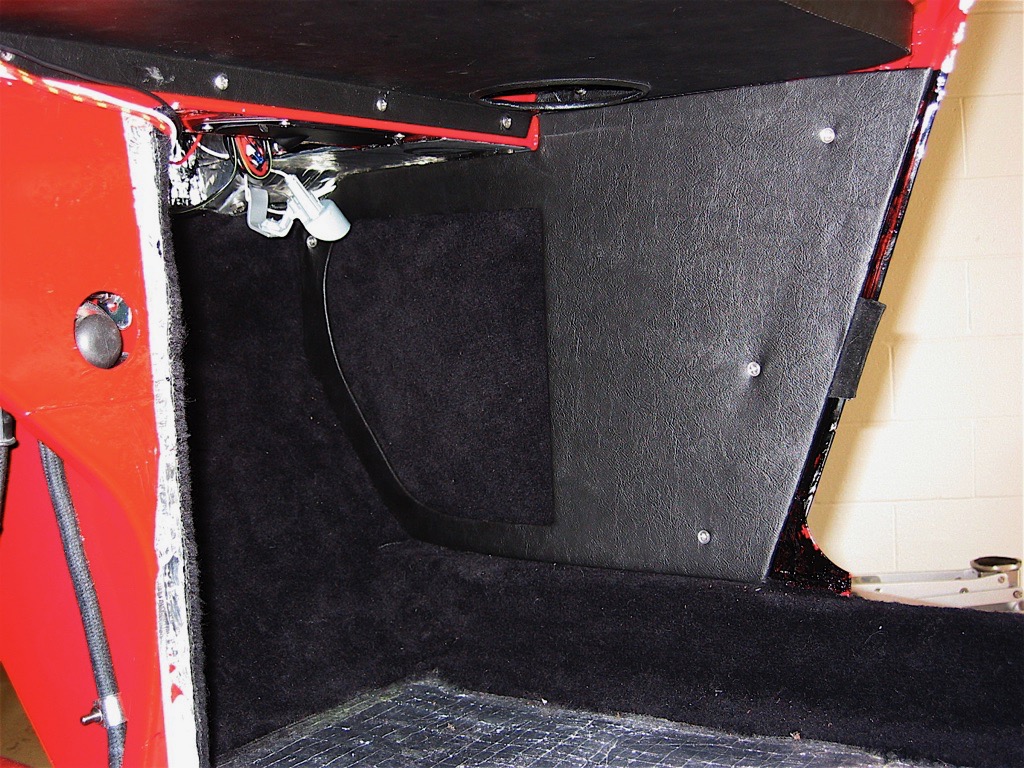
RH Kick Panel

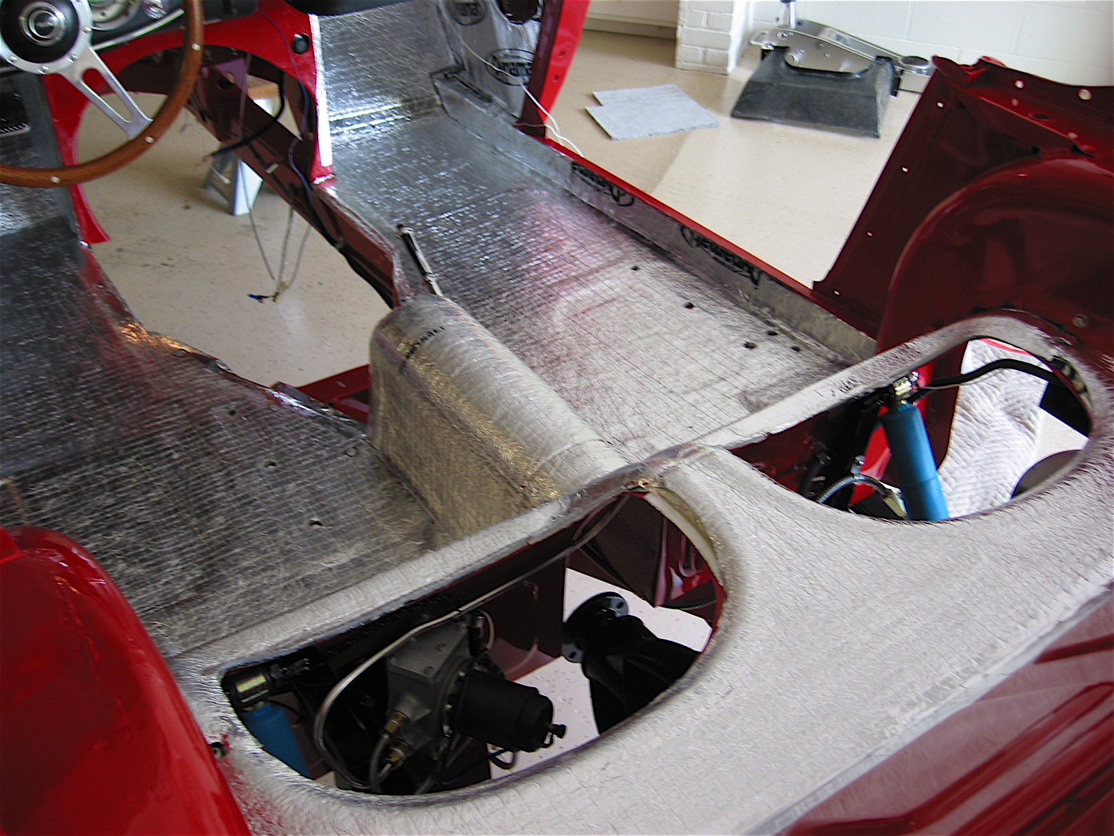
After some trial and error fitting and trimming I put the floorboard carpets in place, cutting the rear most pieces to accommodate the seat rails and their mounting strips. I am going to try using velcro for these pieces rather than snapping them in place since I would have to drill holes in the new floorboards for the snaps. I will see how the velcro works and return to the snaps if my solution is not satisfactory.

The two vinyl covered rear quarter panels were installed next. Four #8 flat head stainless wood screws were used on the vertical rails and two #6 pan head screws were used on each of the top horizontal panels. The front seats were then put in place and tightened. I installed bolt extensions on the fasteners on the driver’s seat seat rails to slightly angle (tilting rearword) the driver’s seat. This proved to offer a better driving position for me.
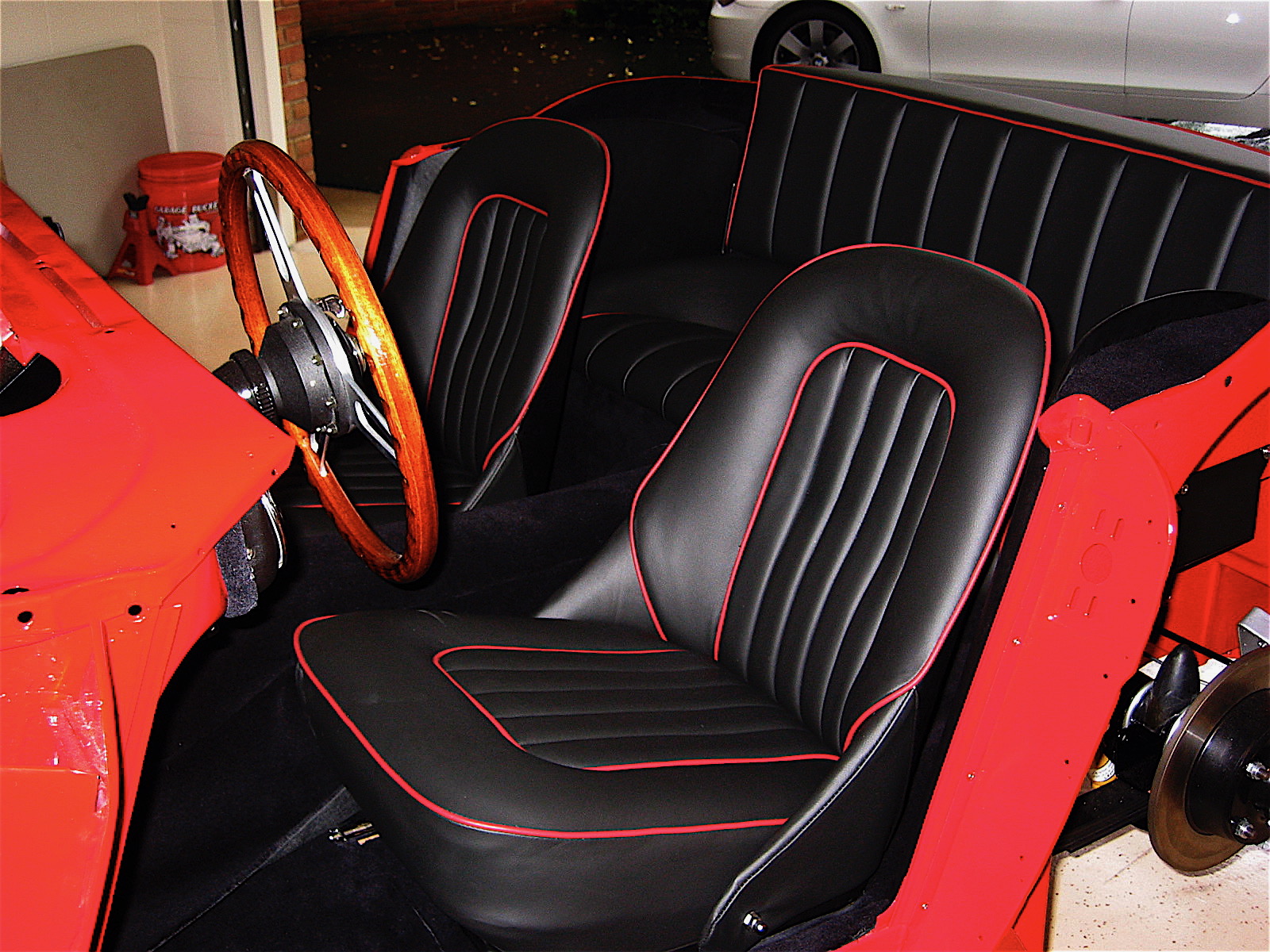
Assembled interior

Assembled interior 2

I am going to delay fitment of the gearbox extension cover and gearbox cover carpet until I have the engine and gearbox in the car just to be sure I end up with a good fit.

Chapter 53 Restoration Assembly, Week Twenty-Three 5/21/2007

My plan is to devote the next couple of weeks to getting the interior finished. This required completing the dynamat extreme application and then adding an additional layer of aluminum insulation of the type that is used around home duct work. I taped all the joints with aluminum tape which resulted in a nice looking job. Of course, looks won’t matter – all the insulation will be covered by carpet or panels, but it should result in a quieter and cooler car!

Interior Insulation 7

Interior Insulation 1

Interior Insulation 6

I was eager to get a little carpet into the Bloody Beast so I pulled out my carpet installation instructions from Rich Chrysler and the digital images from Heritage Upholstery and Trim. The two together provided all the help I needed. BT7 Carpet Install Rich Chrysler The carpet was also supplied by Heritage. I used the wilton wool option and was very impressed with the quality. The first piece in was the LH side rail. All the carpet was secured with Weldwood brush on contact cement.

Editor’s note, May 2020: Rich Chrysler’s son, Geoff, has followed in his footsteps. Geoff has his own interior trimming business named Rightway Heritage Trimming. In addition to his trimming business, he also is currently involved in the restoration of his own 1953 BN1. He keeps an on-line Blog with information about his business projects as well as his own restoration. He posted the following information which provides superb guidance on the installation of a BT7 interior. This link will direct you to a pdf file of the post. Geoff Chrysler BT7 Trimming

Interior Insulation 4

Chapter 52 Restoration Assembly, Week Twenty-Two 5/14/2007

After a few gorgeous days on at the Chesapeake Bay, I am back at finishing the boot. I glued down the left Armacord panel that covers the trough and extends to the rear shroud. I am going to wait on the right one, under the battery, until the shroud is mounted. The new aluminum fuel tank was then put in place. The pipe connection to the fuel line was made at the rear of the tank, and the two securing straps were bolted down.

At the suggestion of other British Car Forum members, I added a ground wire from the fuel sending unit to the frame and I connected the power wire to the sending unit terminal.

Fuel sender wiring

The spare tire staple was mounted to the floor of the boot with two flat head machine screws and the leather strap was inserted. I put the spare in place just to see how things would look and fit.

Spare tire staple

Spare tire installed

Next, I moved to installing the fuel filler neck hose and the filler neck (pipe). I tightened the lower clamp, but will wait until the shroud is installed to finally secure the upper clamp. The blue paper towel in the image to the right is just there to protect the paint until final assembly. The Aston fuel filler cap was screwed on and the corner cardboard cover was screwed on with six #6 screws and trim cups.

Fuel filler pipe

Aston Filler cap

The boot lid striker was then loosely attached to the rear skirt rail support with three 1/4” hex bolts. It will be tightened in place following the installation of the shroud and the rear boot lid.

Boot Lid Striker

The choke knob and cable were the next items to be addressed. The original BT7 had its choke located below the dash, but as with later cars, I decided to place mine on the dash fascia. Because my only option was to drill a round hole in the fascia, rather than the stamped hole on the later cars with a “flat” at the top of the hole to hold the cable unit when tightening the nut on the back side, I improvised with a chrome nut on the front of the fascia as well. I actually made it by cutting off the back of an extra side curtain bezel. It fit perfectly and won’t be recognized by the untrained eye.

Choke Knob 2

Since I am using 2” HD8 carbs instead of the stock HD6 carbs, I also used the BJ8 choke control body bracket mounted on the firewall. Other Healey owners have reported problems with the return mechanism on the choke, so I drilled the remote control cable block and tapped the holes for two #4 stainless screws to secure the carb cables in their fittings.

Choke Control Body Bracket

Choke Cable Block

The LH fresh air intake assembly was then installed, and the control cable was attached.

Air Control Assembly 1

The bonnet latch remote control rodwas the next item to install. While it wasn’t a problem, it would have been easier to install before the dash fascia was affixed!

Hood latch remote control rod 1

Hood latch remote control rod 2