
Accelerator Pedal Assembly
The accelerator pedal assembly was in good shape. I replaced the rubber pad on the accelerator pedal with a new one. I left the set screw restricting the pedal travel as it was found, as well as the two felt washers located at each side of the pedal boss.
The bracket assembly was cleaned and painted with POR 15. It is secured to the floor with four pointed 1/4″ – 28 x 5/8″ hex head bolts with split washers. The pedal is connected to the bracket with a 1/4″ fulcrum pin, flat washer and 1/4″ – 28 nylock nut.

Accelerator Pedal Assembly

Bracket Assembly, Mounting Accelerator Pedal to Floor
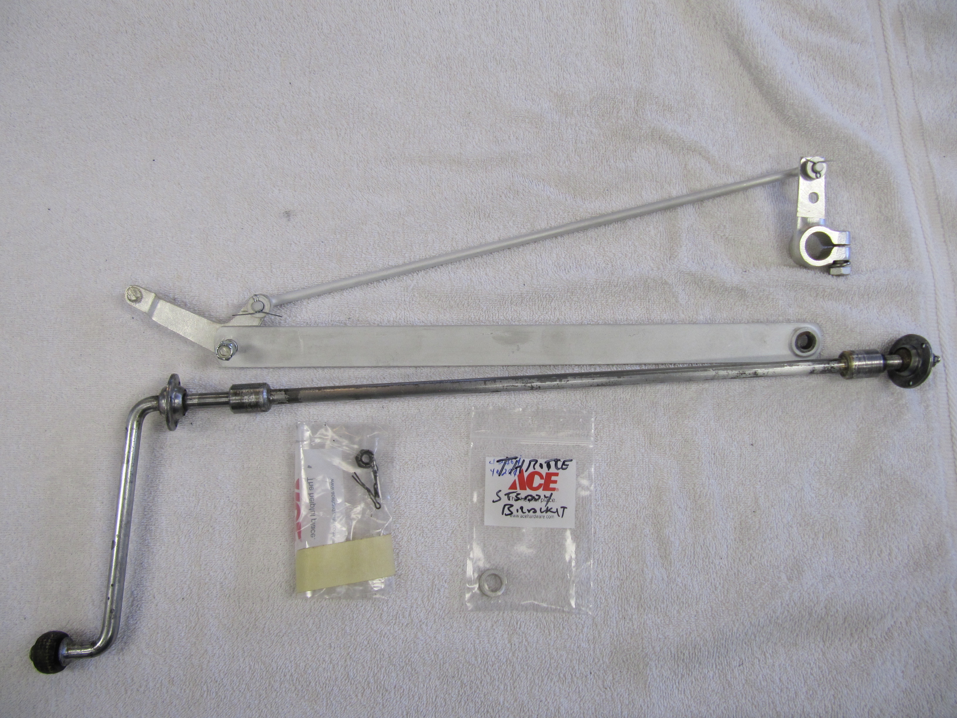
Accelerator Shaft Assembly
The image below depicts the components of the accelerator shaft assembly:
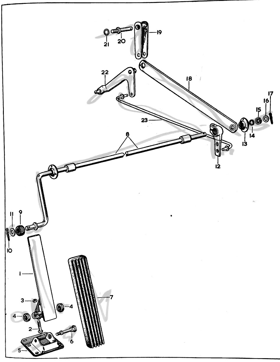
Accelerator Pedal Shaft Assembly Graphic
The shaft was slightly bent so I straightened, cleaned and polished it. The spherical bearing assemblies will be lubricated and reused and will be installed with new pop rivets to the body. The throttle lever, screws, spring washers and flat washers; the steady bar between the cross shaft housing and the connecting link; the bell crank lever assembly; and the control rod assembly were all cleaned and clear cad plated.
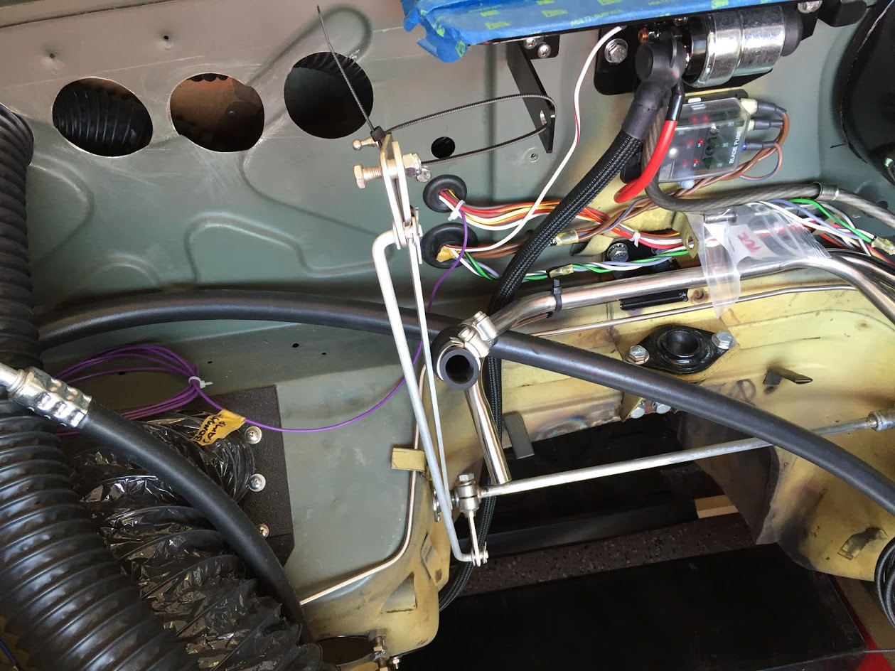
Accelerator Controls
In anticipation of installing the engine into the car for testing, I installed the accelerator shaft assembly into the car. This would be more easily done prior to the installation of the steering column, but I was able to successfully work around it.
Having removed the split pin, flat washer, spring washer and the RH spherical bearing from the shaft, I inserted the accelerator shaft from the driver side into the engine compartment.
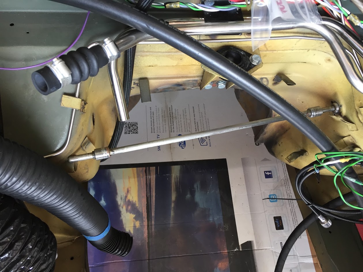
Installing the Throttle Shaft Assembly
I then installed the throttle lever, the steady bar (with the bell crank lever, and the control rod assembly, linking the cross shaft lever and the bell crank lever), the RH spherical bushing onto the shaft and and slipped the shaft into the mounting hole on the RH side of the car.

Pedal Shaft Assembly
Because I am only temporarily installing the throttle assembly in the car, I used #4 machine screws with flat washers, lock washers and nuts to hold the spherical bearings in place at both mounting points. Upon final assembly, pop rivets will be used.
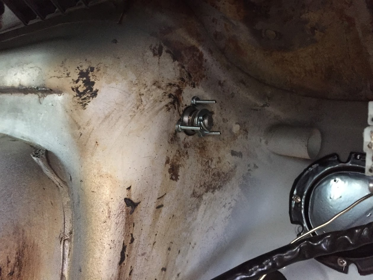
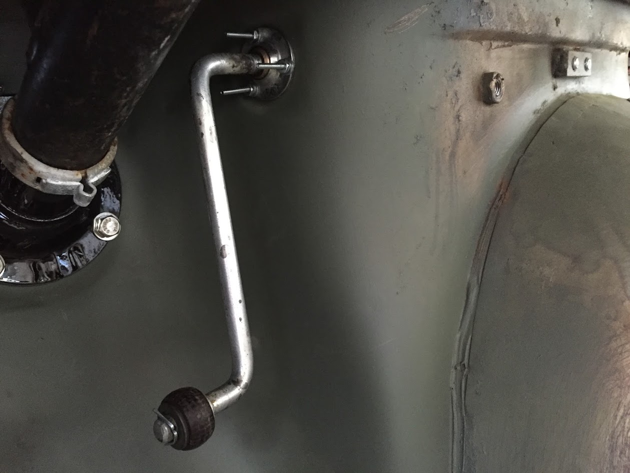
RH Spherical Bearing in Place
In the passenger side (RH) footwell, I then slid the distance piece, spring washer, and flat washer onto the shaft followed by a split pin to secure the shaft assembly.
The assembly was then zip tied out of the way for engine install.
Accelerator Shaft Assembly
This is the LH side of the assembly prior to installing the accelerator pedal.
Accelerator Pedal Shaft Assembly and LH Spherical Bearing and Pedal Shaft Roller
Finally, the pedal assembly described earlier was mounted to the driver’s side floor with four 1/4″ – 28 x 1/2″ hex head bolts with lock washers. These bolts are fastened into captive nuts welded to the floor underside.

Accelerator Pedal Assembly Mounted to Floor