
Engine Cooling
Water circulation is assisted by an impeller type pump mounted on the front cover of the engine, the system being pressurized and thermostatically controlled.
The Cooling System
Water Pump and Pulley
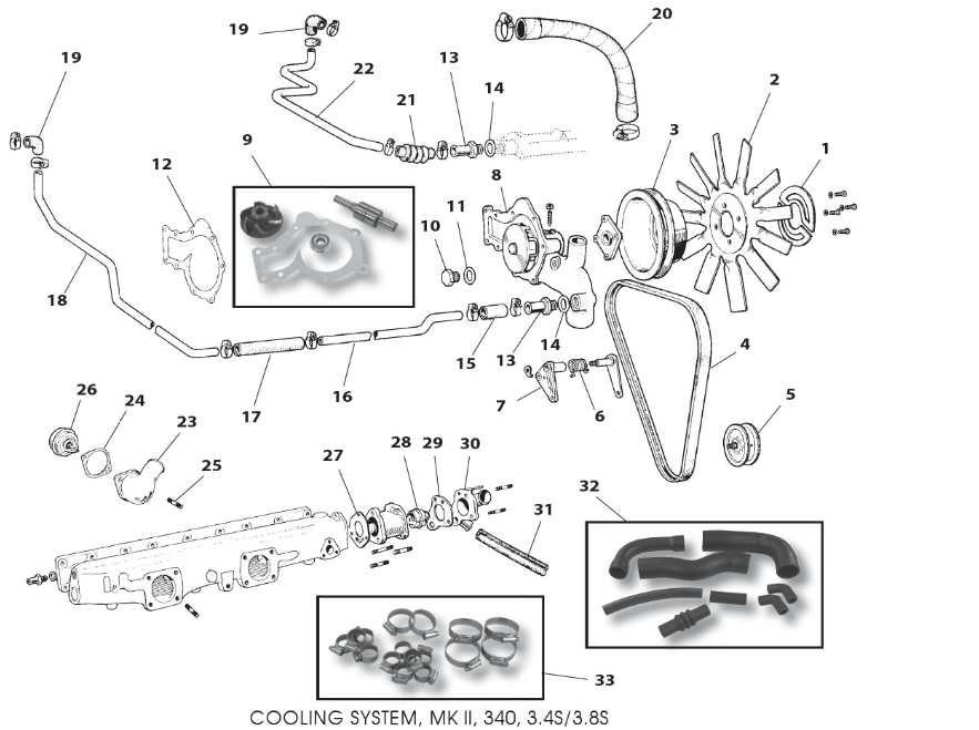
I replaced the original water pump with a new “upgraded” unit sourced from SNG Barratt.
Water Pump
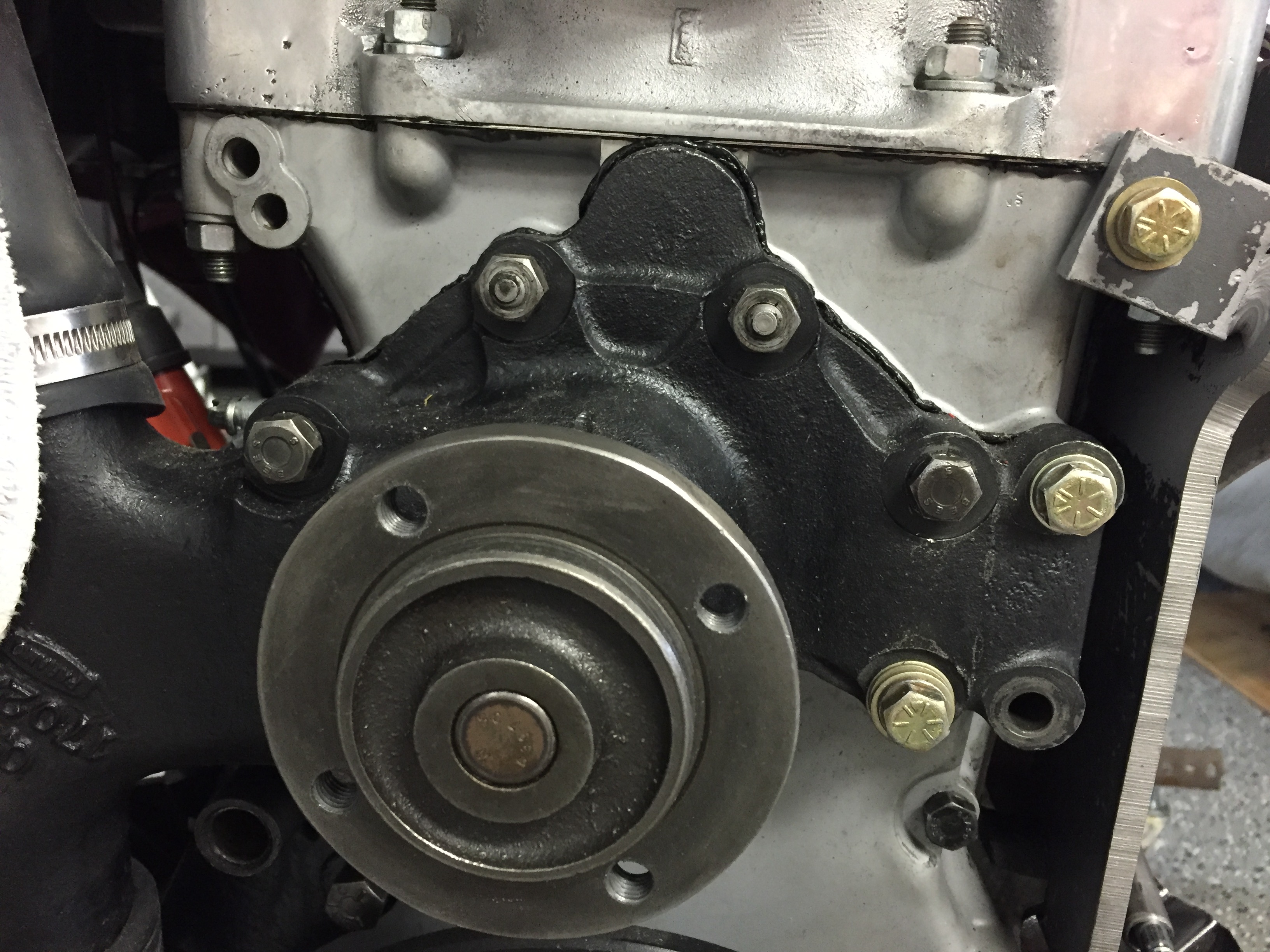
An alloy “V” belt water pump pulley was purchased with the air conditioning components from RetroAir. It measures 5.65″ in diameter and is secured to the pump with four 5/16″ – 24 x 1-1/4″ hex bolts
Water Pump Pulley
Belt, Driving Fan
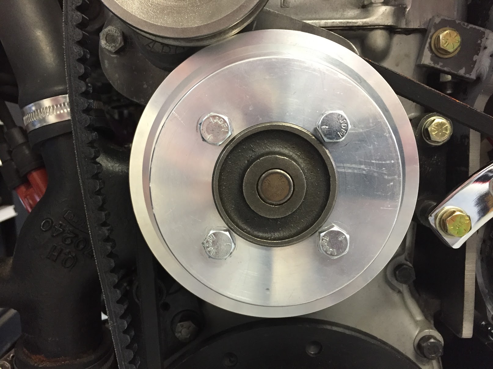
I used a 1/2″ “V” belt ordered from Advance Auto Supply. I like to get expendable items like these at a common auto supply house when possible so that if the belt breaks I can easily pick up a new one. The belt in the image below is NOT the one that I ended up using. The belt rides on the crankshaft, water pump and alternator pulleys and it is a DAYCO 17415 13A1055 that is 41.5″.
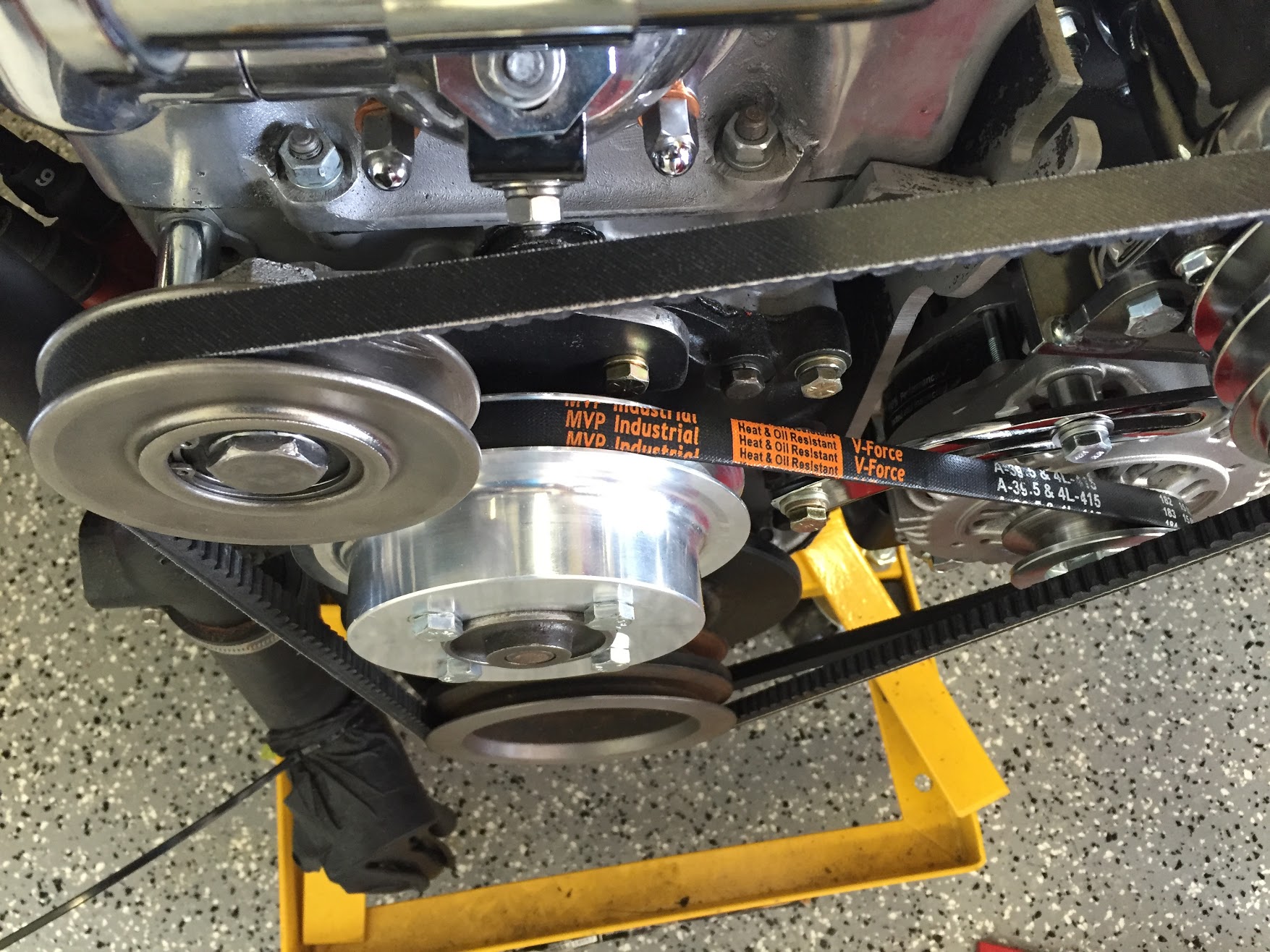
Classic half inch V Belt 39.5 Inside Measurement and 41.5 Outside
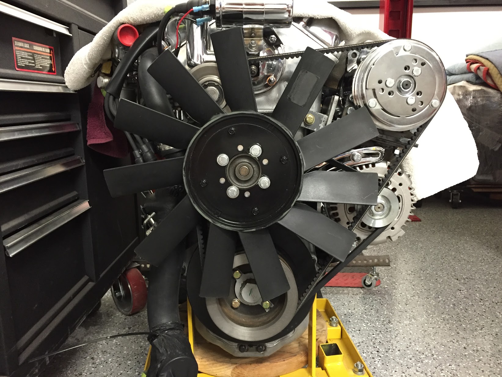
Fan
I installed a higher performance fan than the original. I purchased it from Guy Broad in the U.K. It is some form of plastic/nylon and each blade has a greater angle to catch more air than the original. Unfortunately, I found that to accommodate the air conditioning compressor without conflict, it was necessary to trim an 1/8″ off each fan blade. This was accomplished fairly easily. I will check, and adjust if need be, the balance of the fan before final installation.
Guy Broad Fan
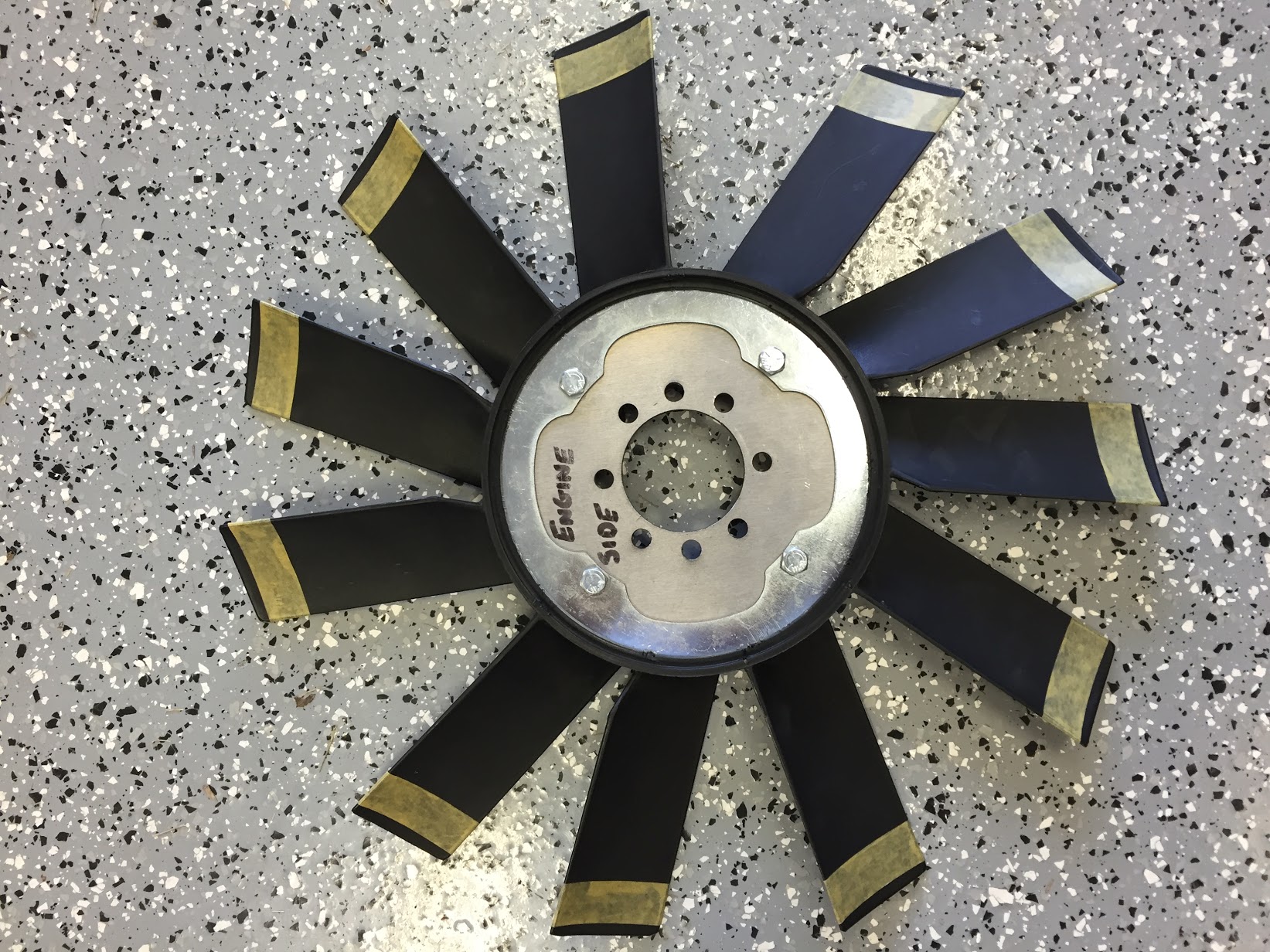
Guy Broad Fan Trimmed to Fit
Adding the belt tensioner pulley for the air conditioning also created a clearance problem with the fan blades. I installed four 1/4″ bushings/spacers between the fan and the water pump pulley to move the fan slightly forward.I used a very small amount of dum-dum to hold the spacers in place as I mounted the fan to the water pump pulley.
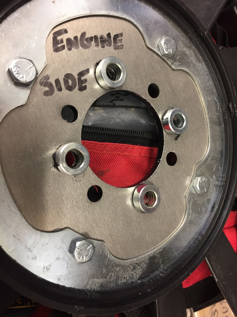
Fan Spacers with dumdum
Moving the fan forward the 1/4″ did not create an issue with the radiator! Because of adding the spacers I changed the original fan mounting bolts to 5/16″ – 24 x 1 1/4″ hex head bolts with flat and shakeproof washers.
Tensioner Pulley and Fan Blade Clearance
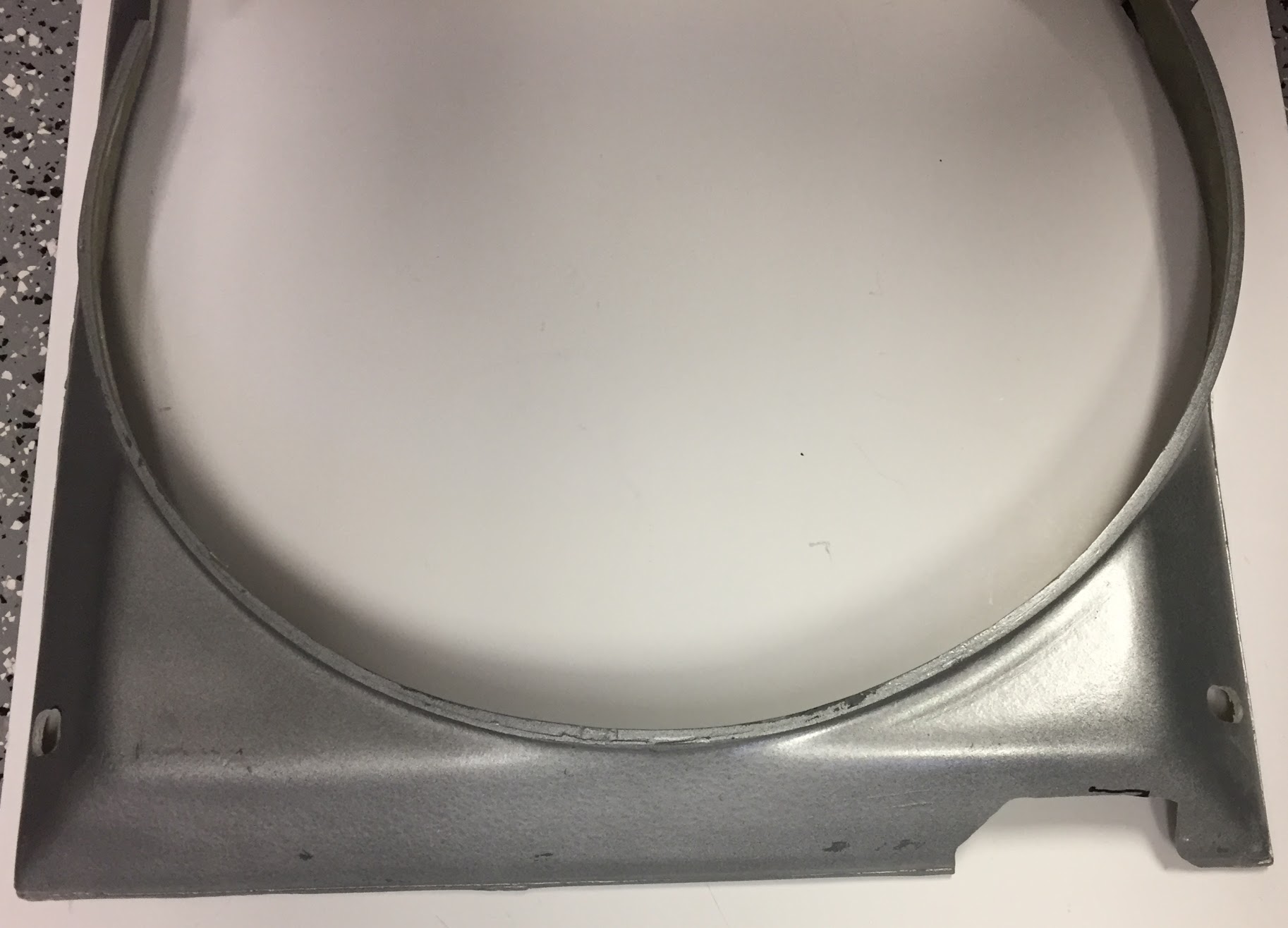
Radiator Fan Shroud
New fiberglass fan shrouds can be purchased from SNG Barratt. I found it necessary to modify the shroud slightly to provide clearance for the air conditioning compressor, the lower radiator tank hose fitting and for the crankshaft pulley.

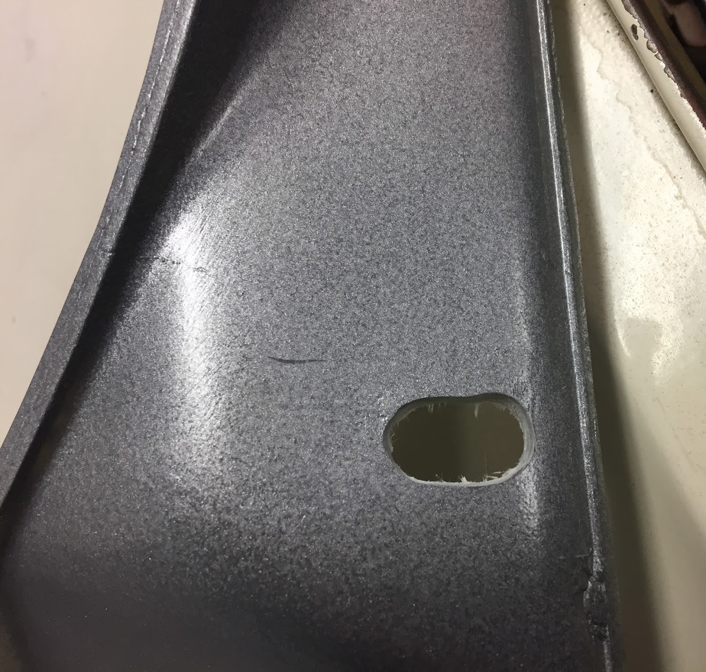
Fan Shroud Opening Modification to accommodate the Sanden Compressor
Fan Shroud Opening Modification for the lower radiator hose fitting
The shroud is secured to the radiator by fastening it to four 5/16″ – 24 studs on the radiator using stainless flat washers, shakeproof washers and hex nuts. the slots cut into the shroud from the manufacturer were not sufficiently large to fit properly so each of the four mounting holes was somewhat enlarged using a dremel tool.
Enlarged Fan Shroud Mounting Holes
After a trial fitting of the shroud I found that I did not like the original silver/grey color of the shroud and painted it gloss black to match the upper radiator tank.
Radiator
I had chosen to replace the original radiator with an aluminum unit made by Wizard to improve cooling and assist with the air conditioning system. I purchased the radiator from RetroAir with my other air conditioning components. It looked beautiful!
I ended up not using the Wizard unit because it did not fit properly. It sat too high, contacting the bonnet, and because of the wider upper tank it did not allow sufficient space for the wiring harness that travels across the front of the radiator from the LH valance to the RH valance. A sad and expensive lesson. I could have modified the aluminum unit to fit but could not solve the wiring harness problem to my satisfaction.
I decided to return to my original radiator but had it recored by Blue Sky Radiator with a modern cooling matrix. I painted the sides of the assembly and the lower tank with POR-15 after using their metal prep product. I then used progressively finer sandpaper to prepare the upper tank surface and then painted it with a Duplicolor self etching primer (three coats) and Duplicolor Engine High Temperature Gloss Black spray paint (also three coats). I just lightly dusted the front of the core with the high temperature paint as I wanted to avoid affecting the heat radiation properties of the radiator to the extent possible. I did not paint the rear face of the core. I was pleased with the results:
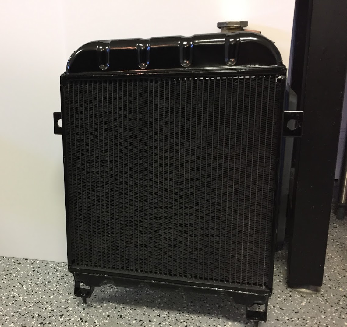
Painted and Recored Original Radiator

Painted and Recored Original Radiator
Installing the Radiator and Shroud
After the fan is mounted to the water pump pulley, it is necessary to loosely position the shroud over and behind the fan.

Fan Shroud in Position for Radiator Install
LH and RH rubber pads and distance tubes for mounting the radiator block to the car need to be located in the mounting holes in the frame.
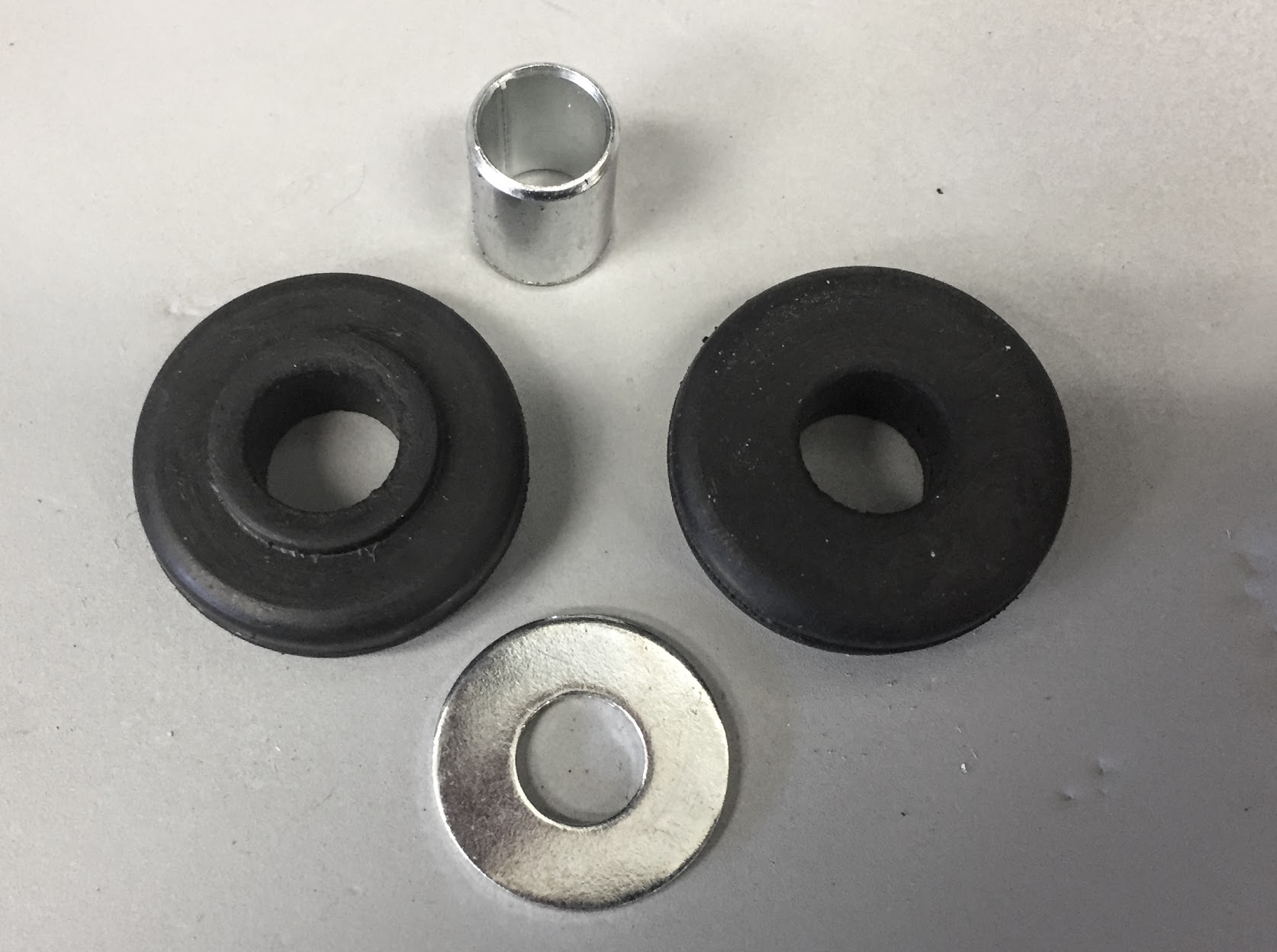
Radiator Mounting Rubber Pads, Distance Tubes, and special washers
One can then carefully manipulate (not quite as easy as it sounds) the radiator downward as the fan blade is turned by hand. The radiator lower mounting studs need to fit into the rubber pads and distance tubes and then through the frame. Once the radiator is in place, another rubber pad, the special washer and a 3/8″ nylock nut can be loosely secured to the mounting stud. The shoulders on the rubber pads need to face the hole in the frame.
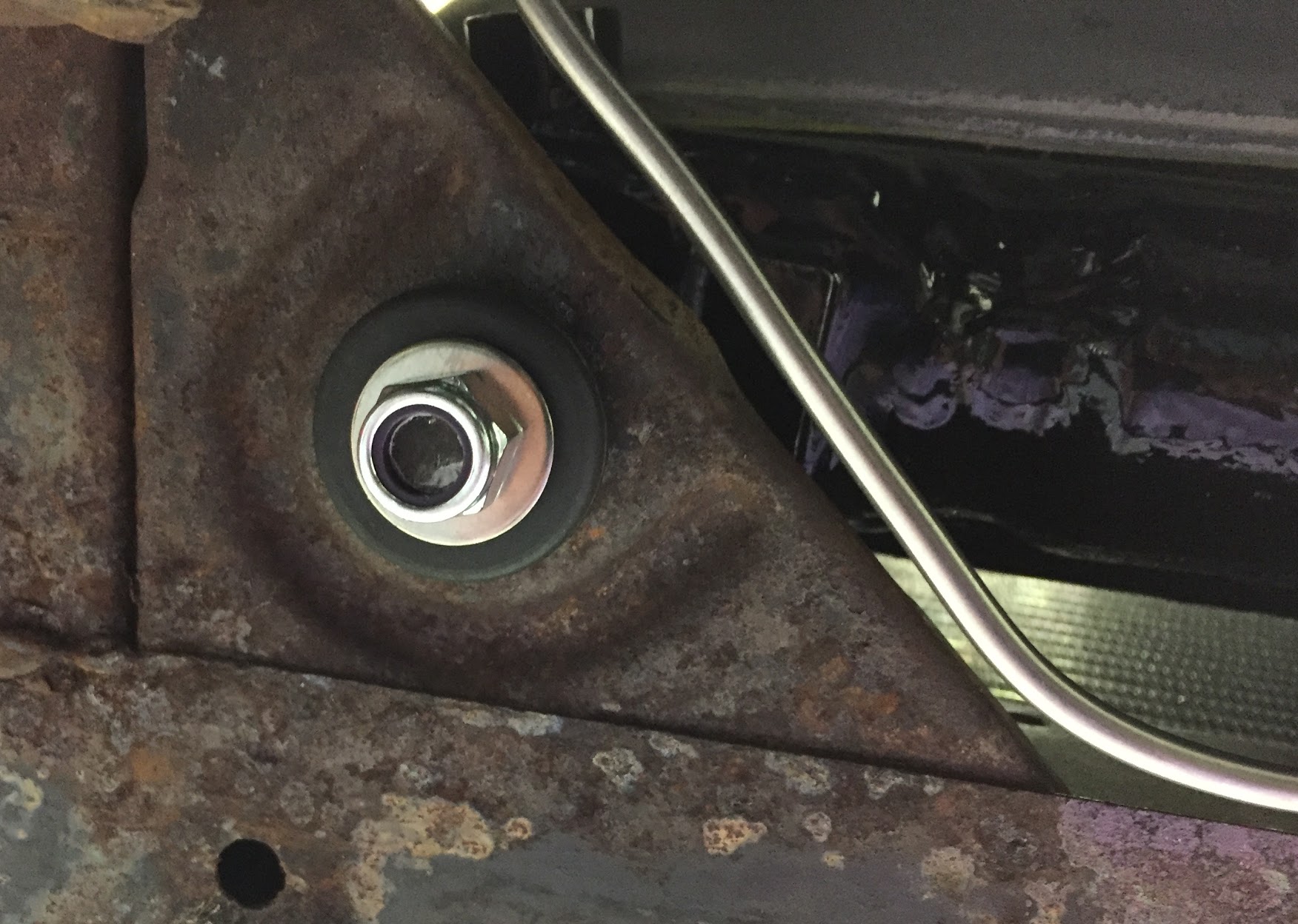
Rubber Pad, Distance Tube, Special Washer and 3/8″ Nylock Nut Lower Radiator Mount
Once the lower mounting hardware is fastened, the two upper mounts on the LH and RH sides of radiator can be secured using the special 3/8″ – 24 bolts, rubber pads and distance tubes. I had cleaned these special purpose bolts and had them zinc plated.
With the four radiator mounting points all secured, the fan shroud can then be mounted to the four radiator studs using flat and shakeproof washers with 5/16″-24 hex head nuts. I then back-tracked and tightened down all the fittings.
Both the upper and lower radiator hoses can then be fitted to the radiator and Jubilee Clips tightened.
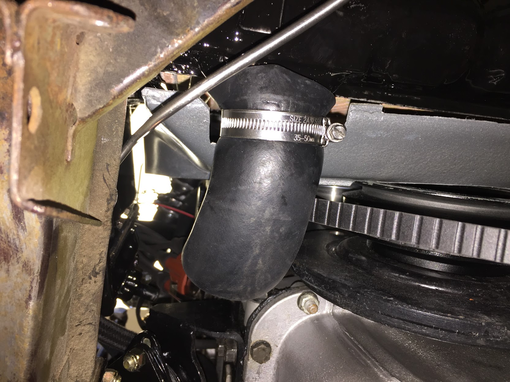
Hose from Bottom of Radiator Block to Water Pump with Size 2A Jubilee hose clip
The images below show the radiator assembly with the black fan shroud mounted in the car:
Radiator, Fan Shroud and Upper Hose in Place
As can be seen in the image above, Jaguar provided an overflow outlet from the radiator neck. I attached and clamped a 5/16″ drain hose from the outlet. For the moment I have it draining to the ground as I am not sure if it will be needed. I plan to use Evans Waterless Coolant in my car. The Evans product supposedly produces very little pressure. This is a subject I will address in greater detail later. Should I find that the drain is needed I will find a place SOMEWHERE for a collector bottle. The image below shows the drain hose and clamp used.
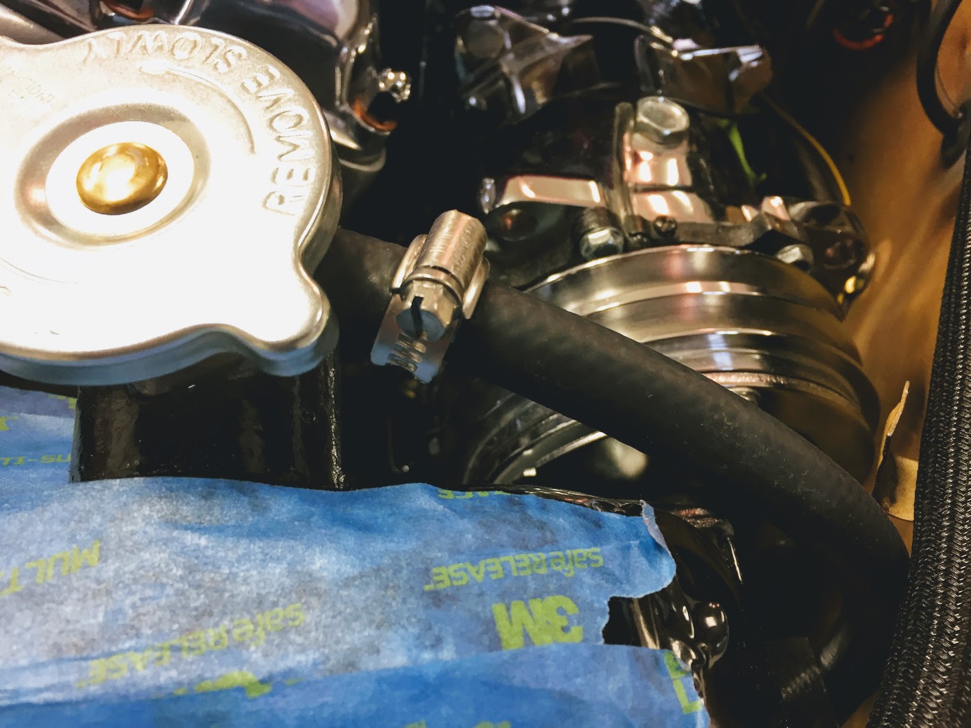
Radiator Coolant 5/16″ Drain Hose
Radiator Drain Tap
I disassembled the brass drain tap and after cleaning and lubricating I reinstalled it in the refurbished radiator. I did not have a fabric washer that fit so I used a rubber “O” ring. The drain tap is not installed in the radiator until AFTER the radiator is mounted in the car. Otherwise it becomes an obstacle in mounting the radiator.
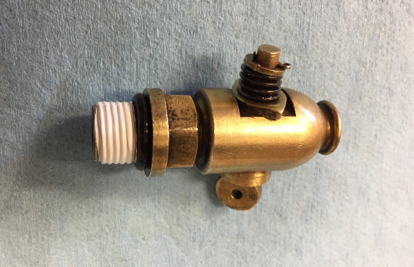
Drain Tap for Radiator Block with rubber O ring
As originally configured, Jaguar provided a proper remote control for the drain tap, allowing the owner to open the drain valve by simply turning the control rod rather than crawling under the car. See the image below. Unfortunately, I am unable to use this control rod because its mounting bracket contacts the air conditioning compressor. I will just have to crawl under the car an operate the drain tap by hand!

Hoses and Temperature Sender
I replaced all rubber in the car including the heater and engine cooling hoses. Here are the three primary coolant hoses with new Jubilee clamps. The top water hose, from radiator block to water pump, the hose from the bottom of radiator block to water pump, and the by-pass water hose.
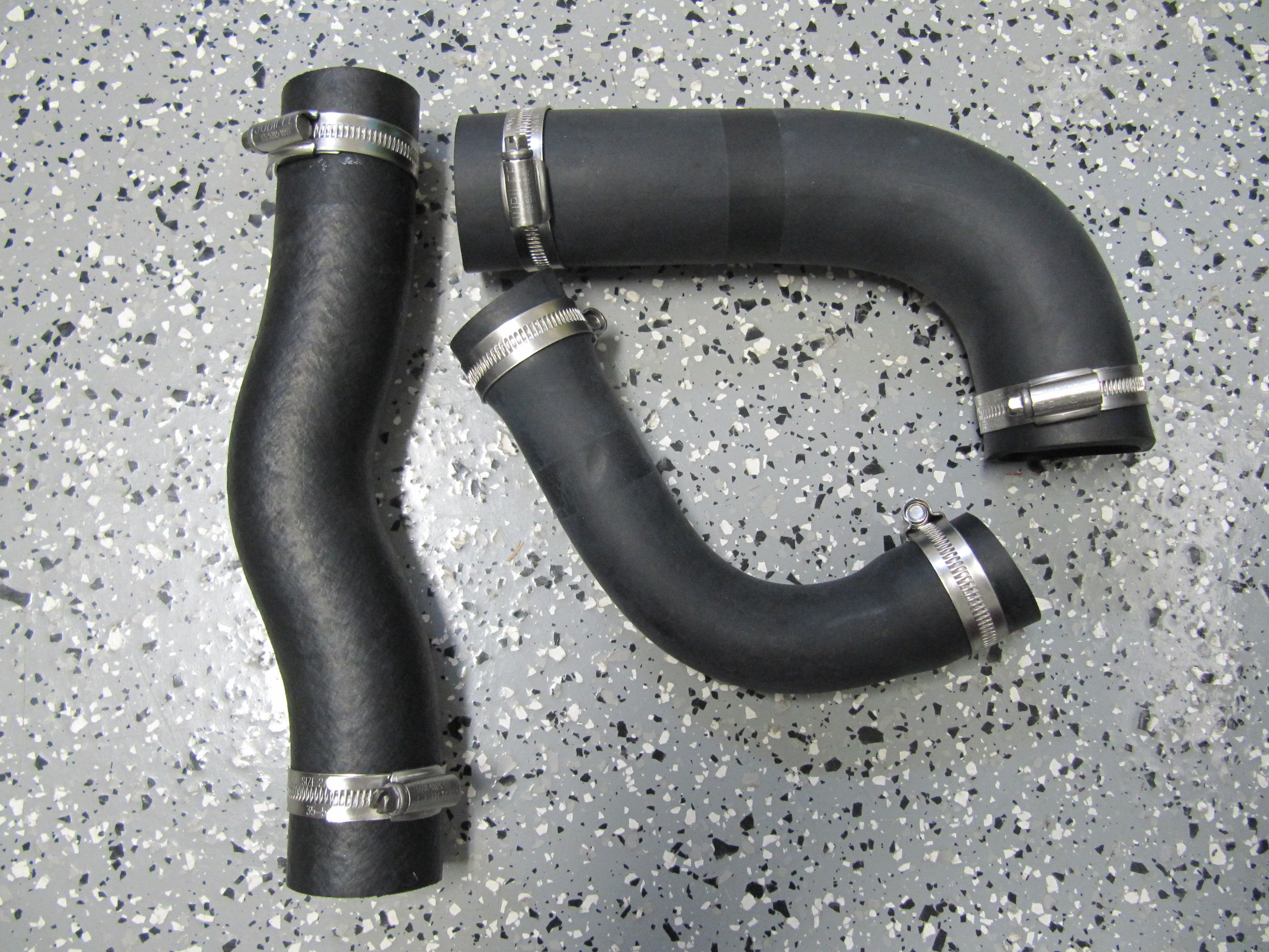
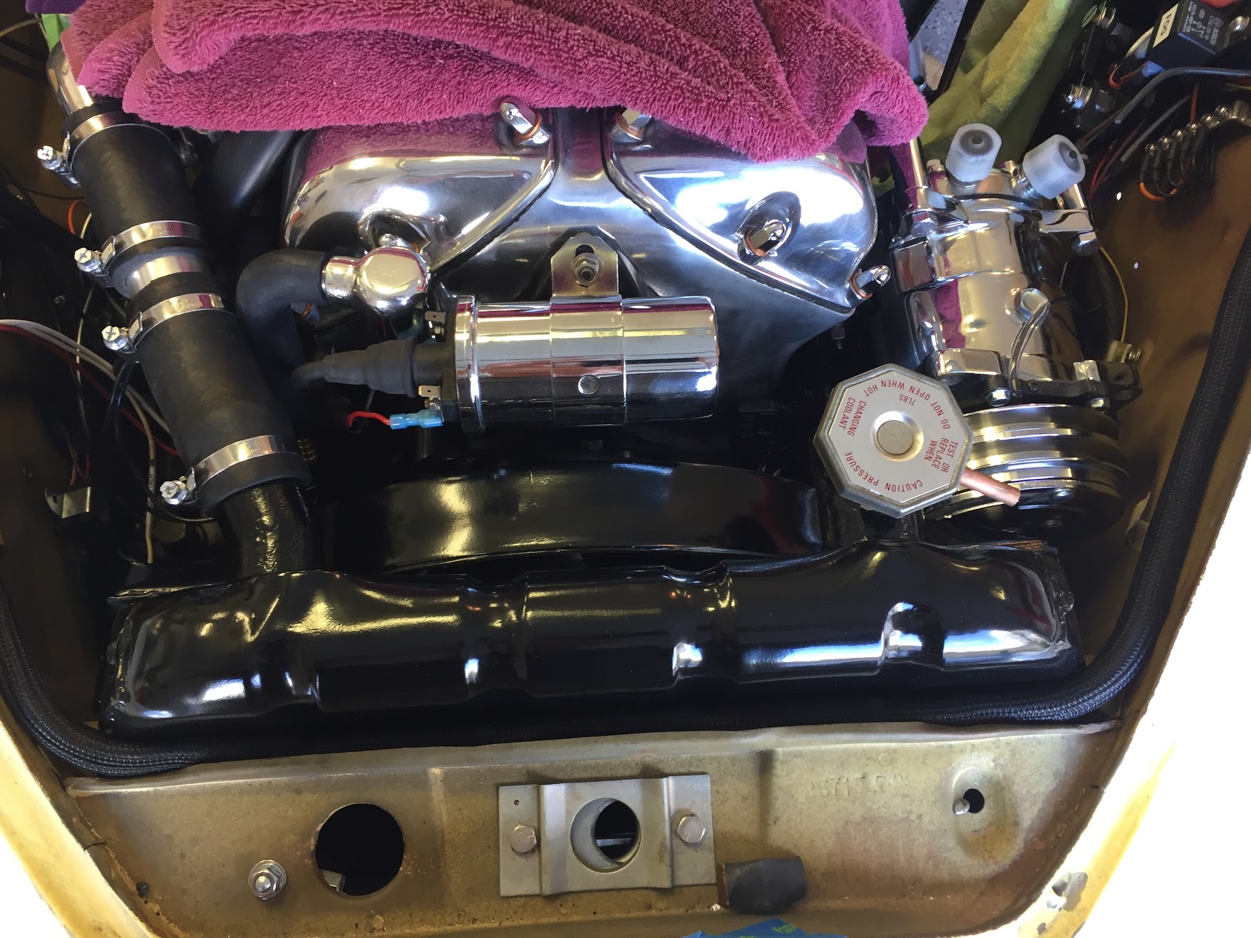
Primary Coolant Hoses
I debated for some time about where to install the water temperature sending unit to control the operation of the electric fan. These are typically placed in the engine, on the lower radiator tank, the upper radiator tank, or in an especially designed coupler inserted into the upper radiator hose. I decided against modifying the original radiator and ultimately chose to use a hose coupler. I cut the upper 1-1/2″ hose and inserted the coupler. The clamps are 32-50mm.
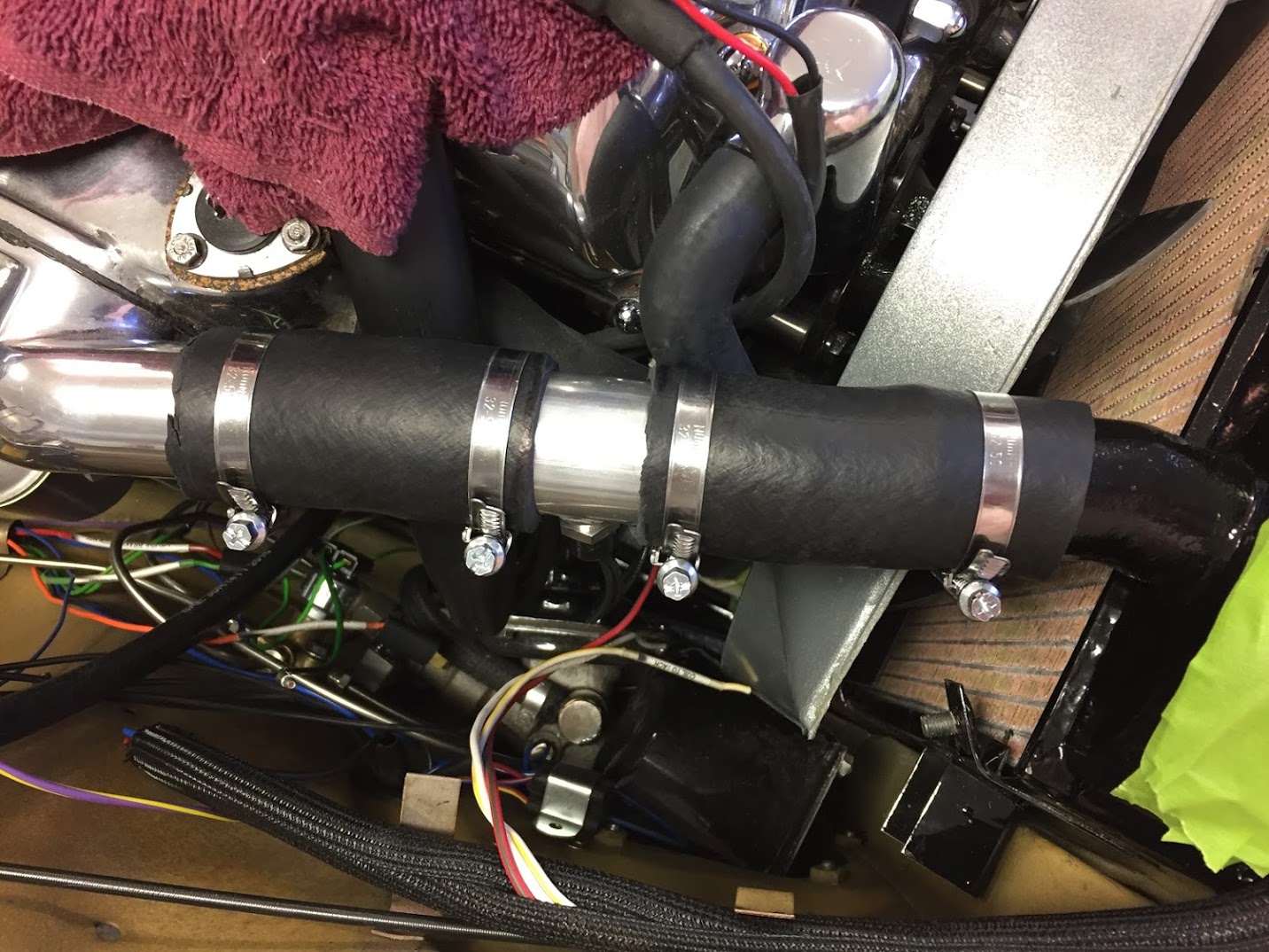
Fan Thermo Switch in Hose Coupler
I used a SPAL Automotive USA IX-185-2TS Fan Sending Unit purchased from Summit Racing Equipment https://www.summitracing.com/search?SortBy=BestKeywordMatch&SortOrder=Ascending&keyword=SPU-IX-1852TS. It threads into the coupler with a 3/8″-18 NPT thread and turns off at 165 degrees F., and turns on at 185 degrees F. I liked this switch because it has a separate wire to ground rather than relying on the body of the switch for ground. The aluminum coupler was purchased on ebay: Radiator Sensor Tube Adapter Water temperature Gauge 1-1/2″ OD 3/8″ NPT (141025992422).
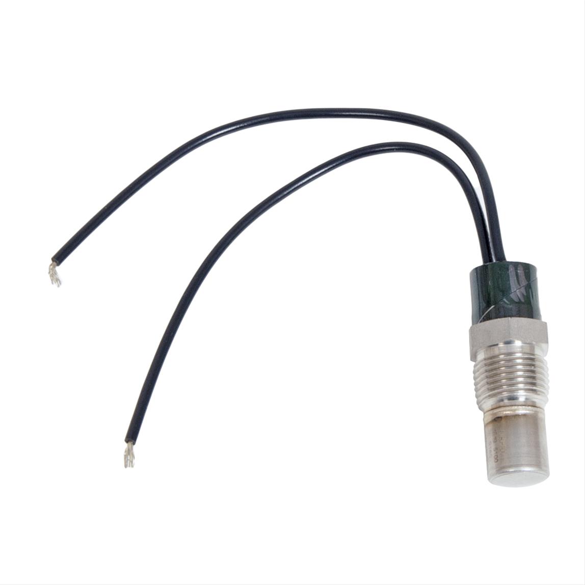
SPAL Thermo Switch
The Adaptor, In Inlet Manifold, For Water Feed to Heater Unit
The original Adaptor, In Inlet Manifold, For Water Feed to Heater Unit was corroded badly, so I replaced the adaptor with a new one sourced from SNG Barratt, including a new fiber washer.
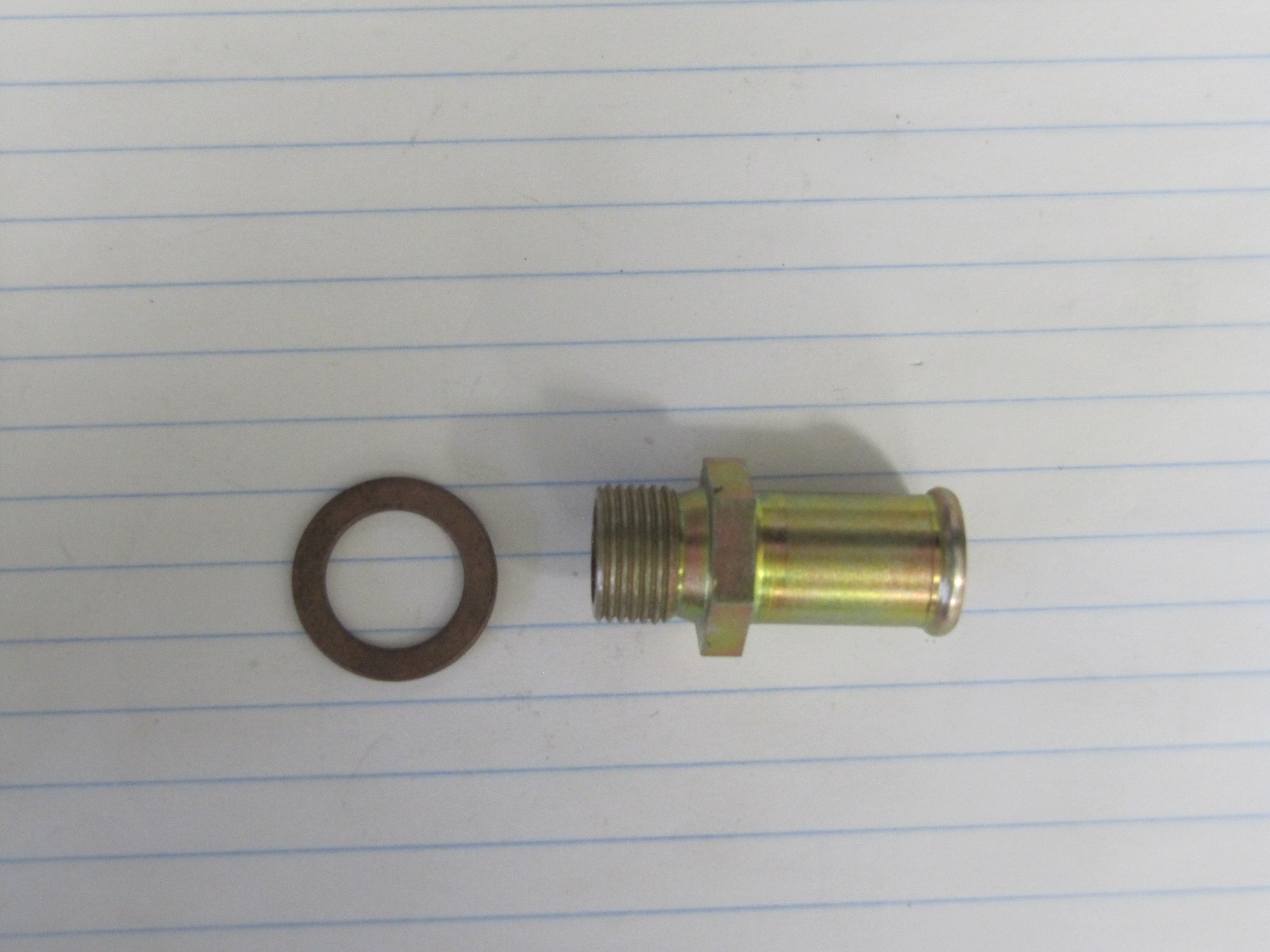
Adaptor In Inlet Manifold for Water Feed to Heater Unit
Radiator Cap
The MK2 used a 4 lb. cap originally and may have gone to a 7 lb. cap later in production. I am not sure. I sourced a new 7 lb. cap from M&C Wilkinson in the U.K. for my MK2. It is important to get the proper length cap so as to achieve the right seal in the radiator neck.
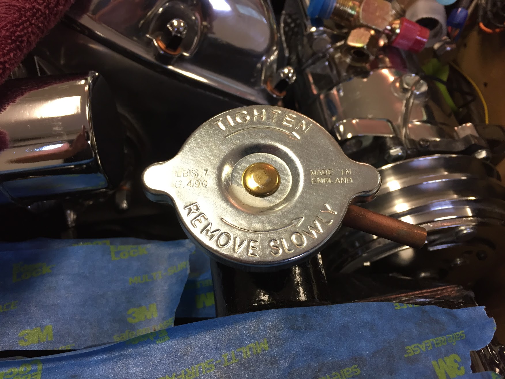
7 lb. Radiator Cap