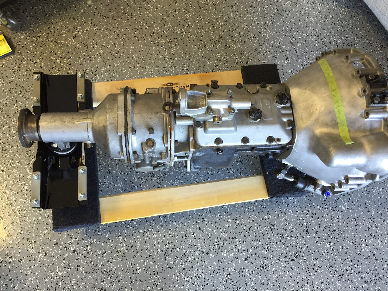
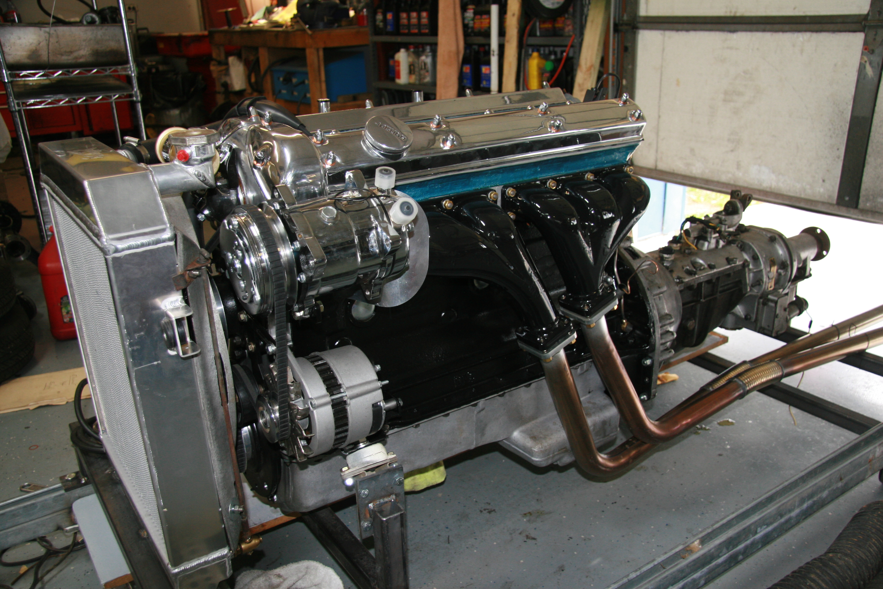
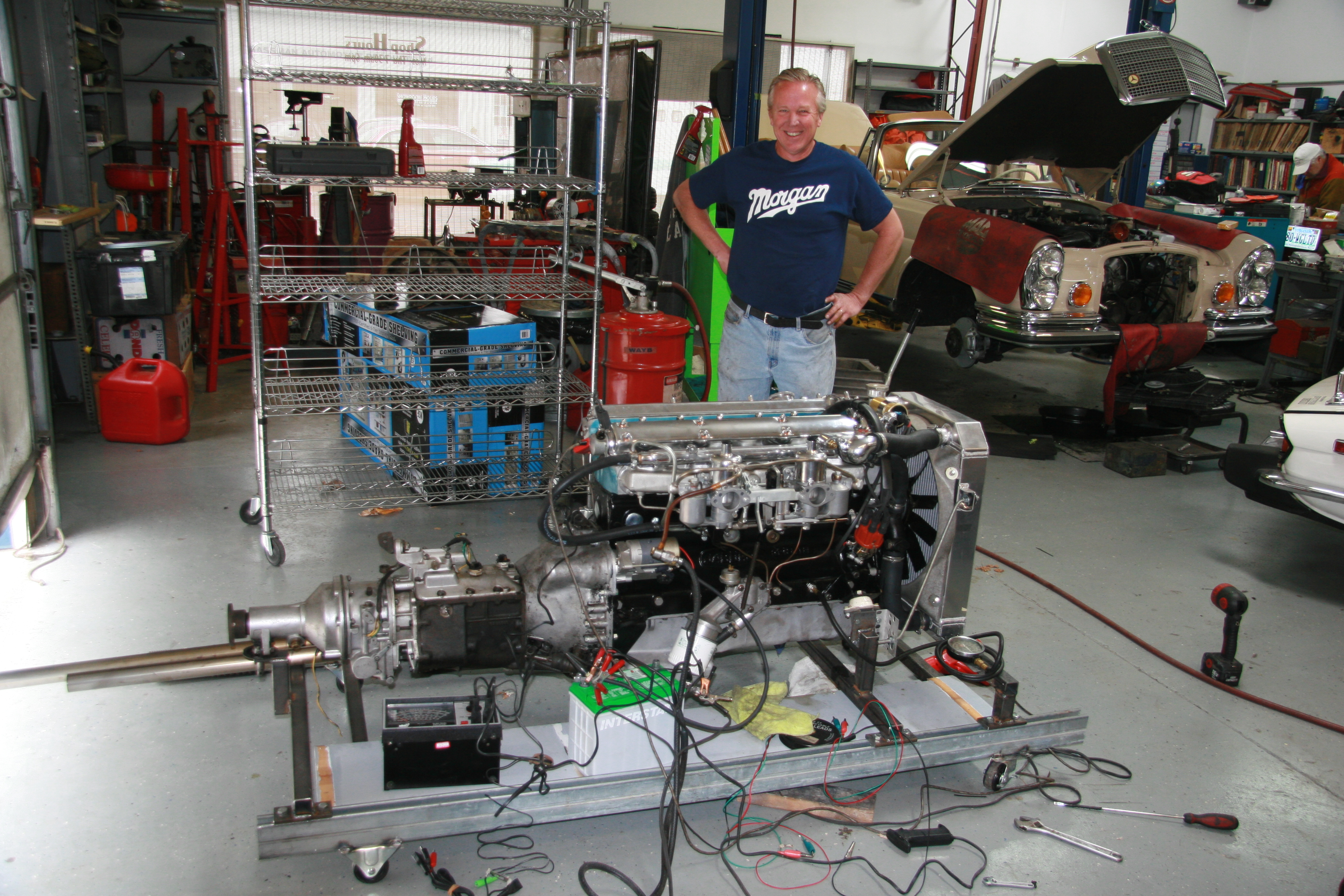
Having just installed my engine and gearbox into the car chassis, I thought it might be useful to keep track of the various related installations and connections that need to be made before one turns the ignition key and hits the starter button to fire-up the refreshed engine. I will try to journal this check list of items in the sequence that they are addressed, though I may find that I need to modify the chronology as things unfold.
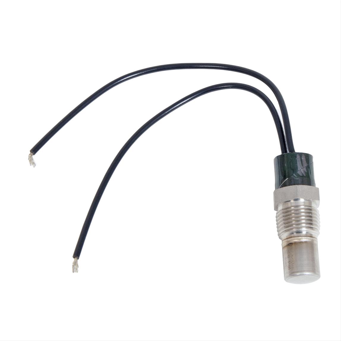
1. Water temperature sensor wire:
Water Temp Sensor Wire at Intake Manifold
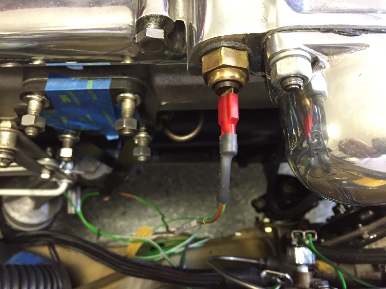
2. Oil Pressure Sensor Wire:

Oil Pressure Sensor Wire
3. Dip Stick – I discovered that the placement of the electric steering pump interfered with the free travel of the dip stick. I found it to be easier to shorten the dipstick than to move the pump!
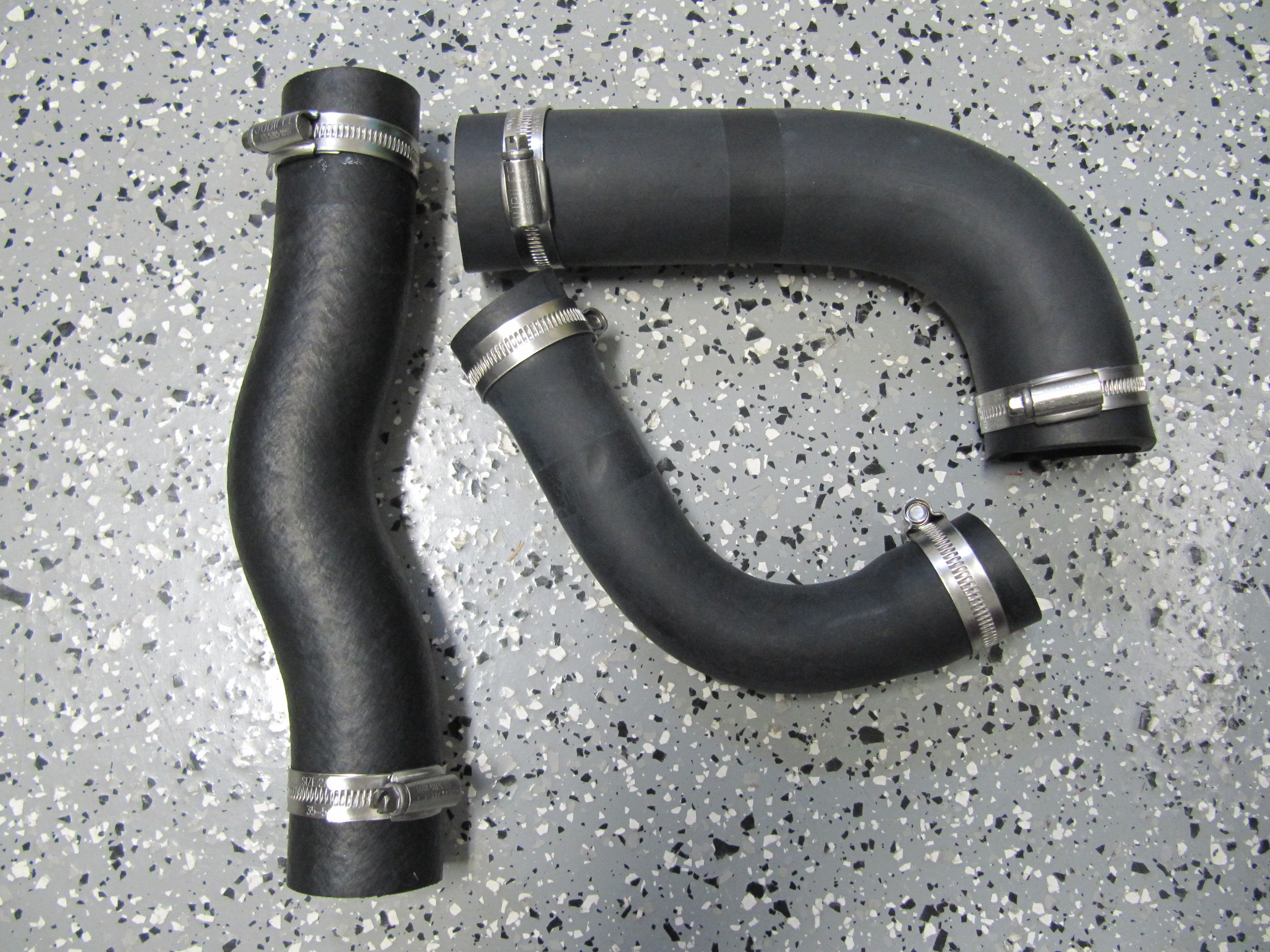
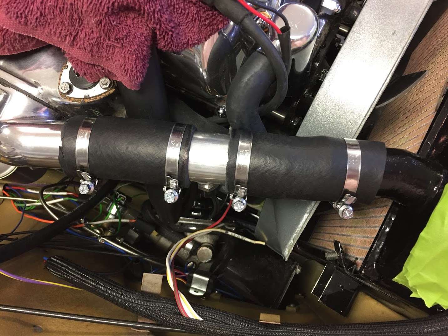
4. Heater Feed Pipe Hose Connection to Intake Manifold:

Intake Manifold Feed Hose to Heater
5. Heater Return Pipe Hose Connection to the Front Return Pipe at the Side of the Cylinder Head – the XK’s Unlimited stainless pipe does not fit well so I have ordered and offset hose to hopefully compensate for the poor fit.
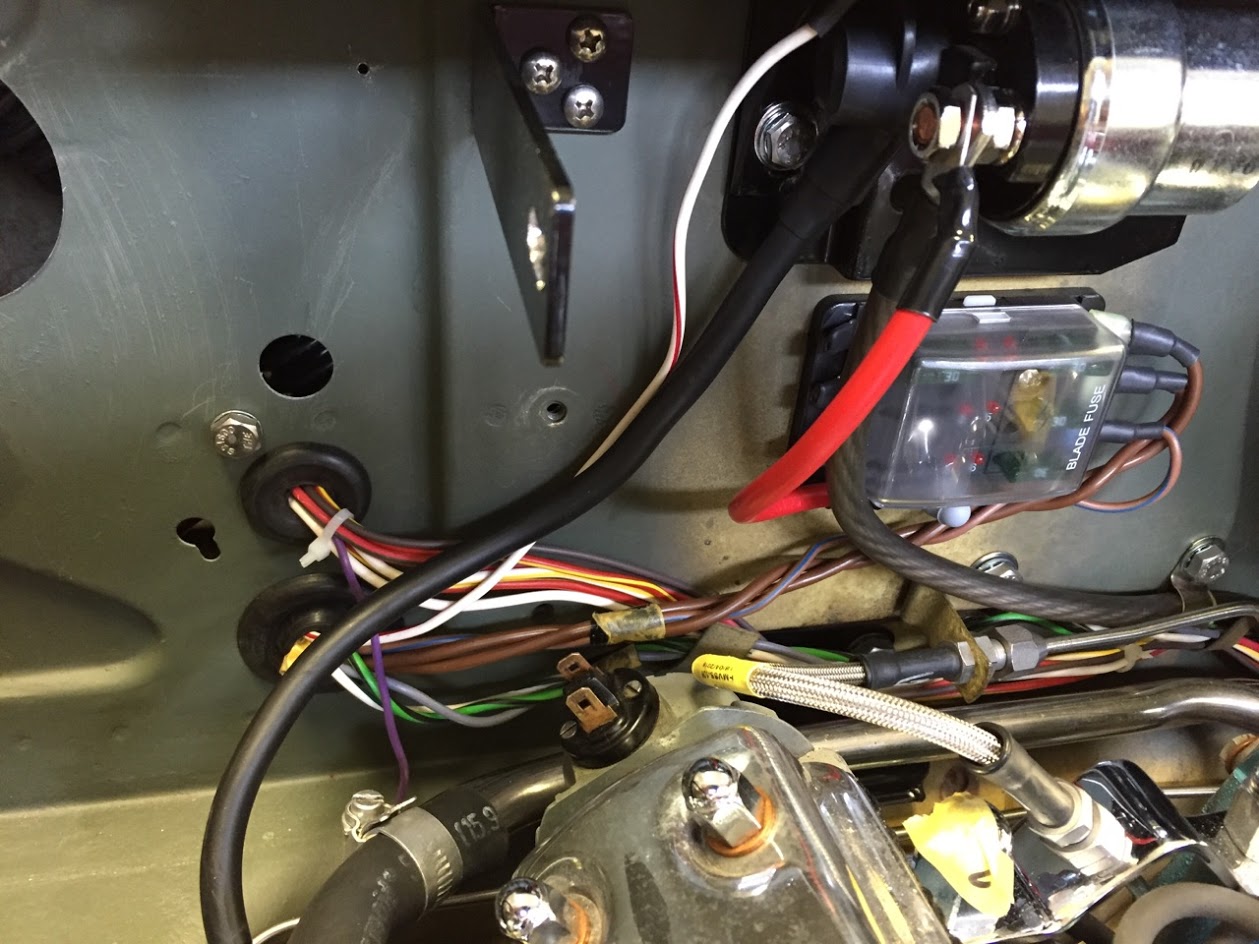
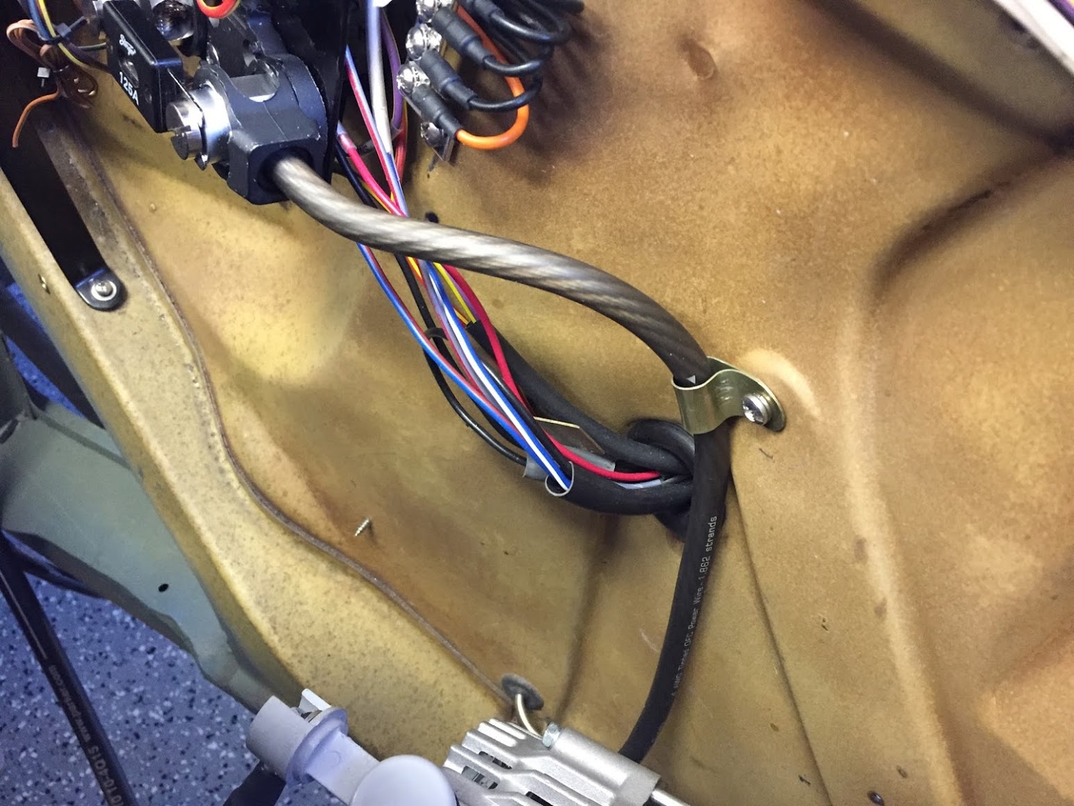
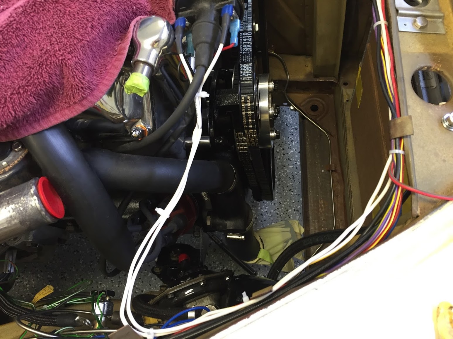
6. Checked the firewall wiring Ground Strap to Chassis path to make sure all of the wiring is routed under the heater pipes, clutch hydraulic pipe and hose and the alternator cable, note the position of the clips. On final assembly the loose wiring will be in a wire look cover:
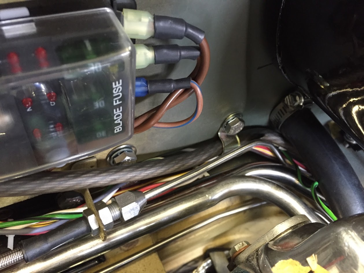
Firewall Wiring
7. Wiring Clips below the heater. Two yellow zinc clips, one for the alternator cable, and the other for the collection of smaller gauge wires:
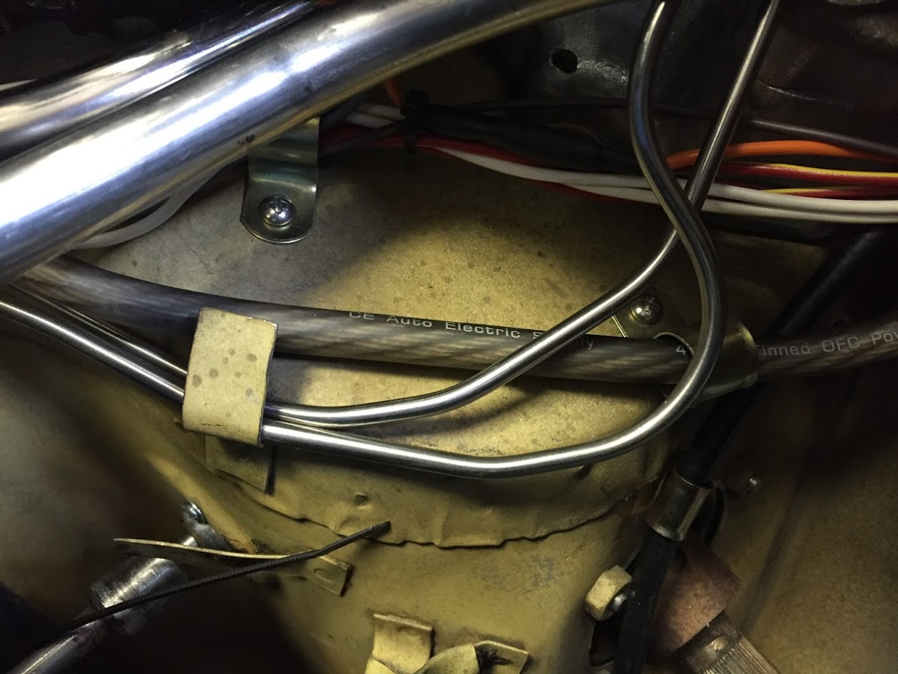
Yellow Zinc Wiring Clips Installed
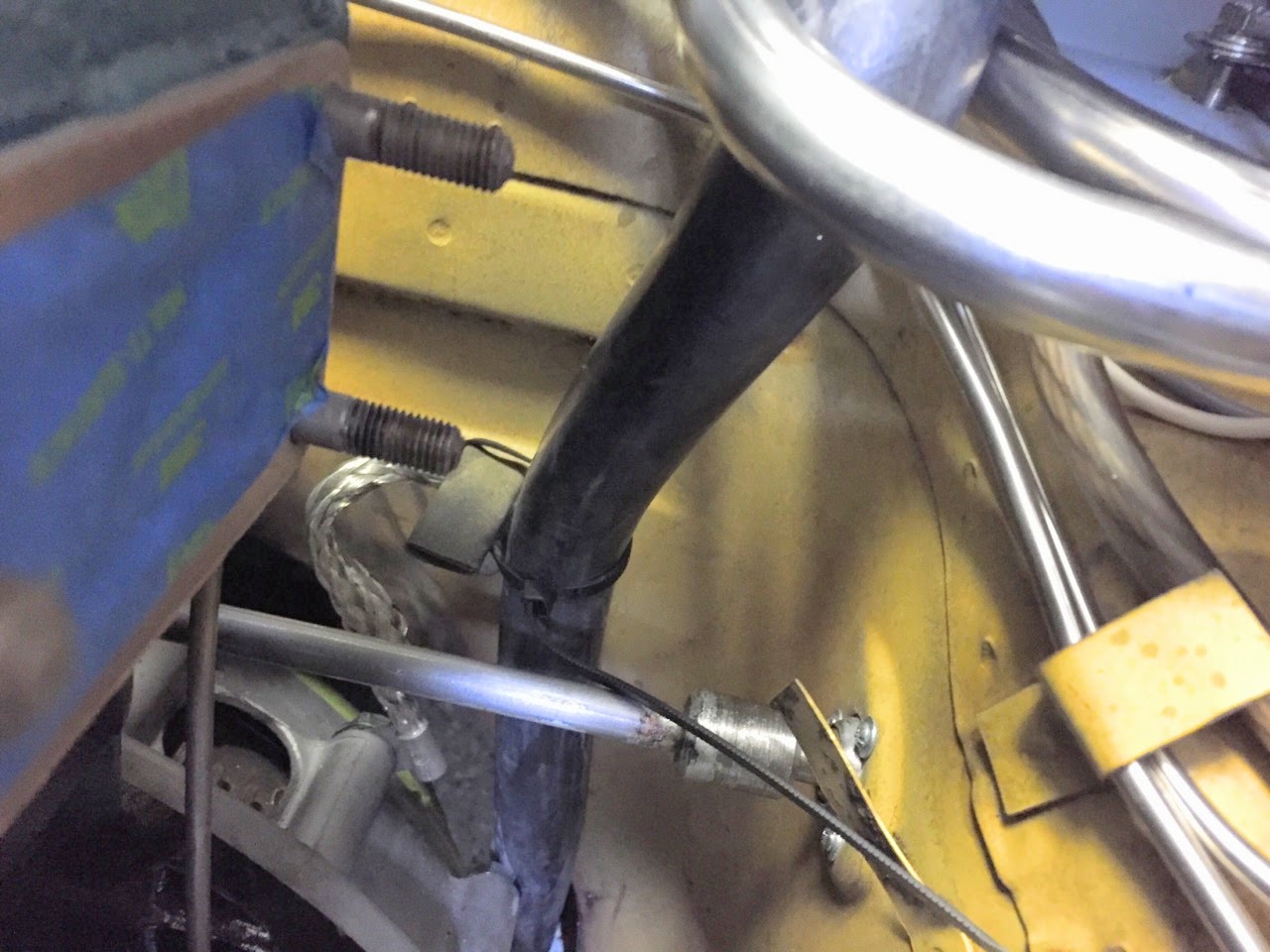
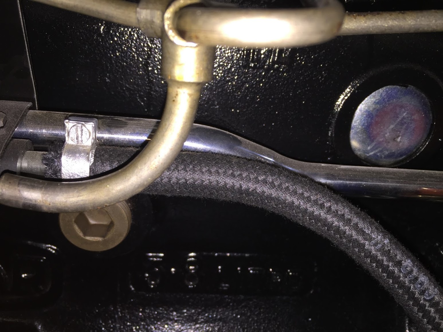
8. Flexible Hydraulic Stainless Steel Hose at rear of the cylinder head:
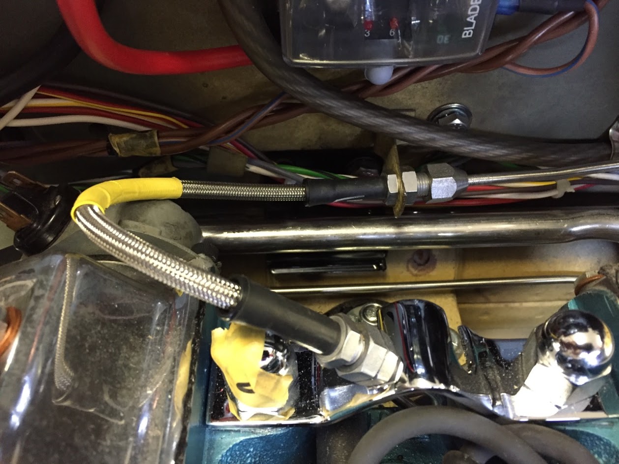
Goodridge Flexible Clutch Hose
9. Starter Cable – The cable was previously connected to the starter. The other end was routed to the rear lug of the starter solenoid and secured with a rubber boot over the connection:
Cable from Starter to Solenoid on Firewall
10. Ground (Earth) Strap – Connected to the firewall with a 5/16″ shake proof washer and a 5/16″ – 24 x 1/2″ hex head bolt:
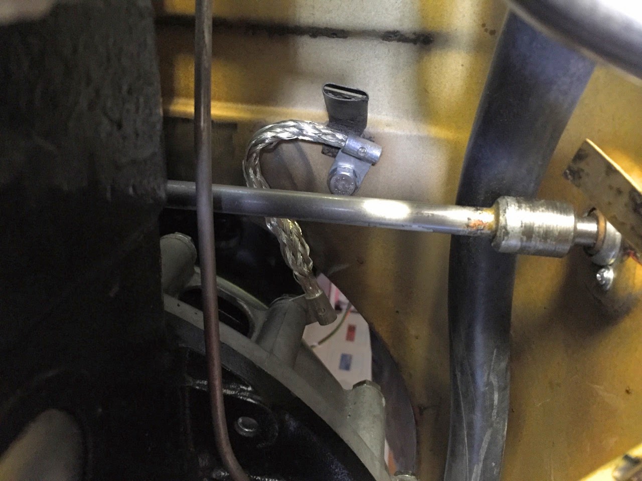
Ground Strap to Chassis
11. Plenum drain hose – The drain hose was secured to the plenum pipe at the firewall with a hose clamp and routed between the chassis and the transmission, behind the throttle linkage. I zip-tied it to the ground cable at the firewall to make sure that it did not rub against the throttle linkage:
Plenum Hose clamp at Firewall and wiring below pipes
Plenum Drain Hose zip-tied to Ground Cable
12. Installed the alternator and its primary cable from the ANL Fuse on the LH engine bay valance. I took advantage of a captive nut already located on the valance as a place to install a yellow-zinc clip to secure the alternator cable.

Alternator to ANL Fuse Cable Installed
Alternator Cable Valance Clip
13. Alternator Pig Tail wiring leads:
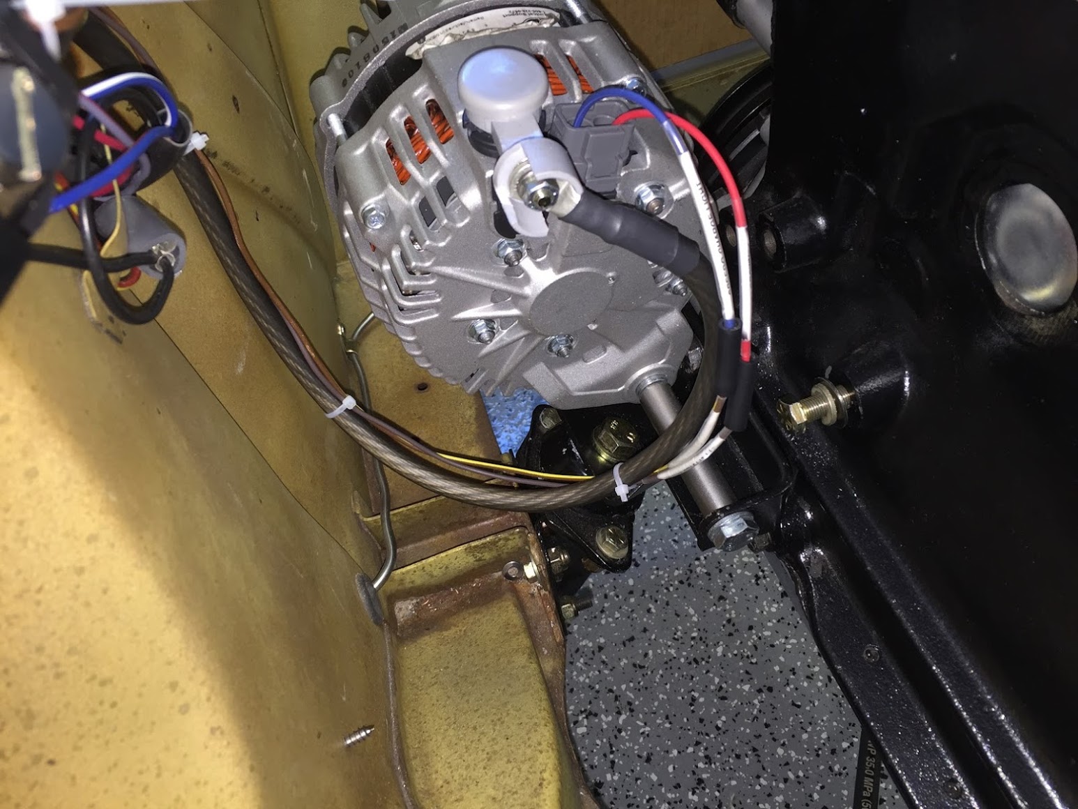
Alternator Cable and Pigtail Installed
14. Compressor – connected the black wire from the compressor with the black wire from the air conditioner drier.
Compressor Wiring to Valance
15. Coil wiring – white wire from ignition, fuse position #6 to positive terminal at coil; and white/yellow wire from tachometer to negative terminal at coil:
Coil wiring Installed Tach to – terminal FP6 to + terminal
16. Reservac Tank Vacuum Hose – from brake servo reservac tank check valve to the vacuum line at the RH side of the cylinder block:
Vacuum Hose from Reservac Tank Installed
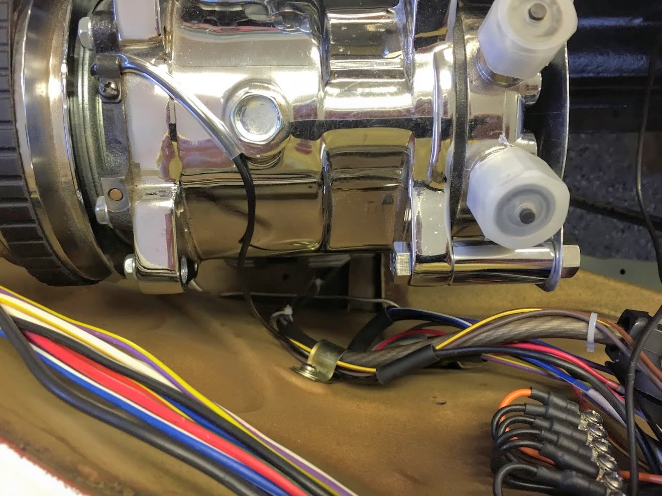
17. Reverse and Top Gear Switch Wiring at Gearbox – Rather than routing these wires as Jaguar did (through the gearbox tunnel) I decided to install a rubber grommet in the tunnel and run the wiring to the interior of the car. Each wire was then connected with two-way snap connectors and will be hidden by the central console:
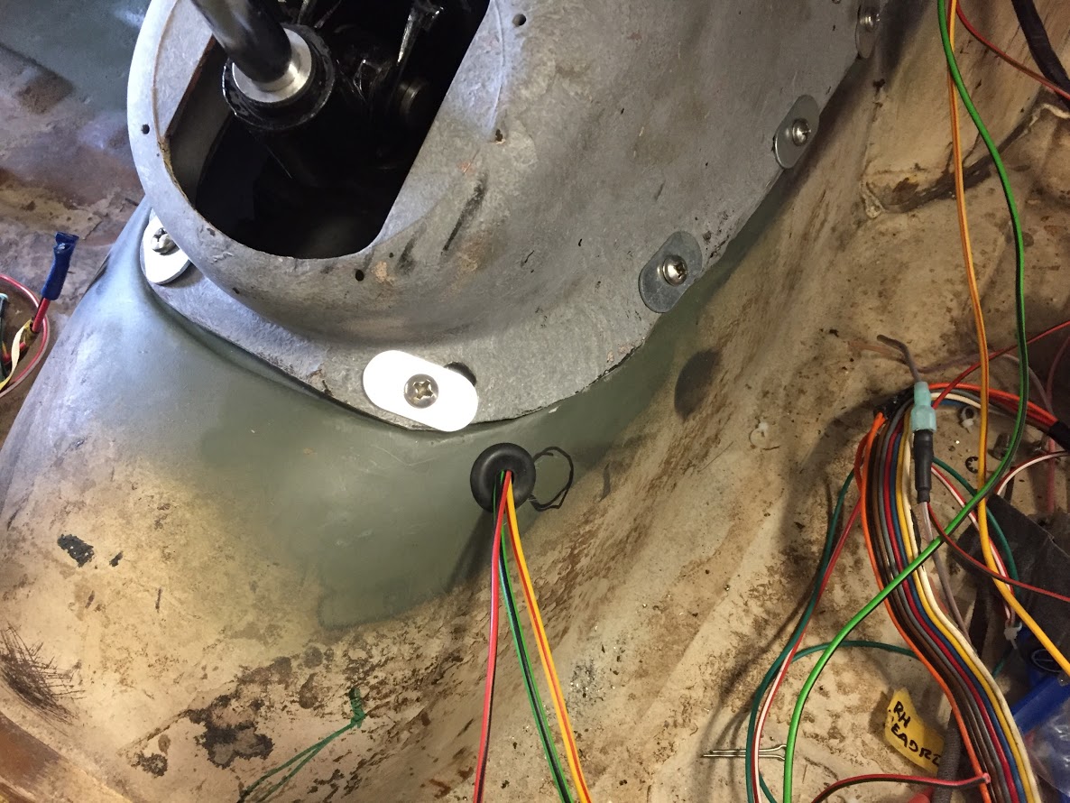
Grommet for Reverse and Top Gear Wiring

Reverse and Top Gear Wiring at Gearbox Cover
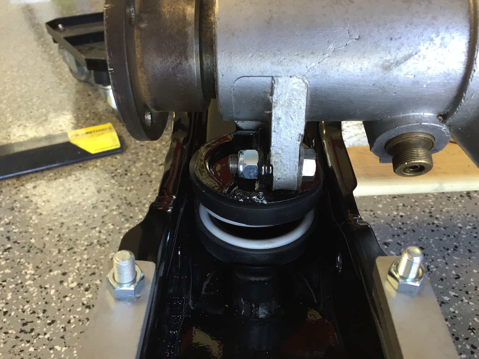
18. Change Speed Lever, Rubber Grommet and Retaining Ring – I removed the lever knob and slid the grommet over the lever shaft ( a little petroleum jelly doesn’t hurt), punched holes in the grommet with an awl and installed the ring and grommet with four #4 x 1″ chrome slotted finishing self-tapping screws.
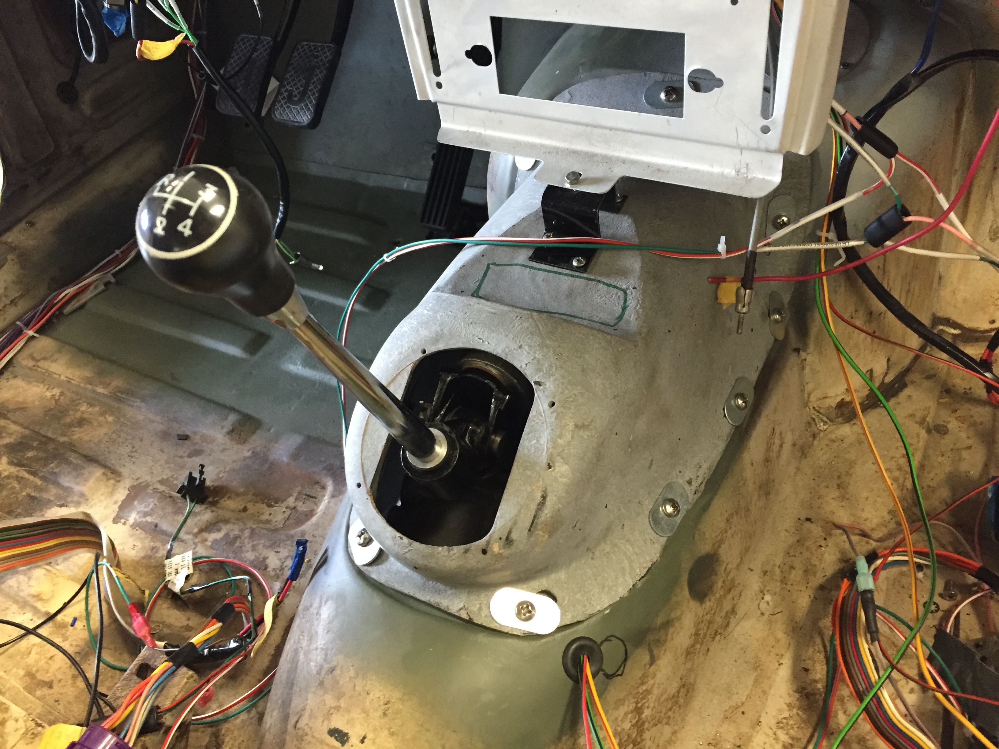
Gear Selector Installed
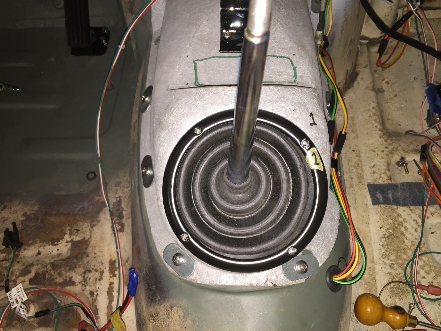
Rubber Grommet on Gearbox Cover for Change Speed Lever
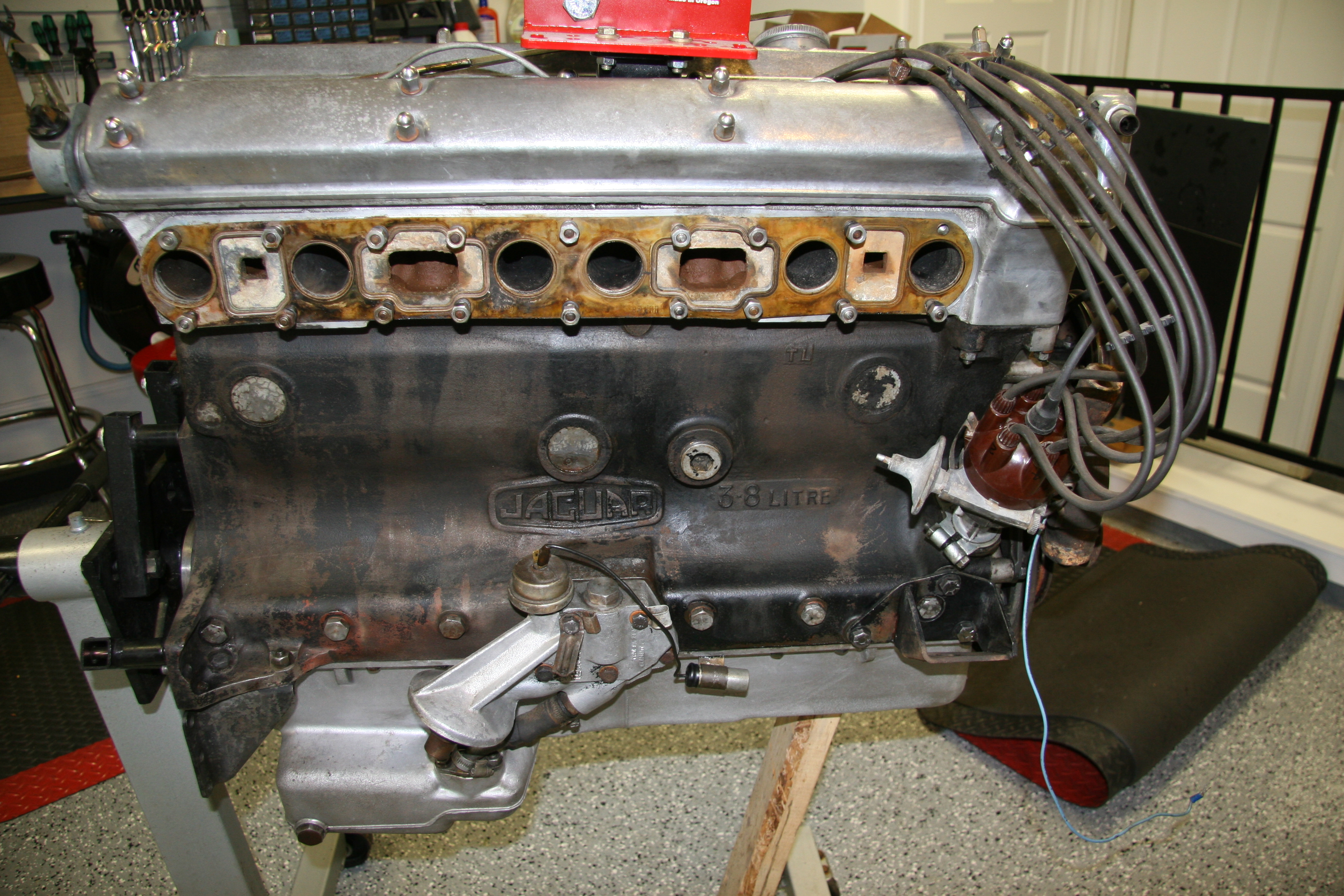
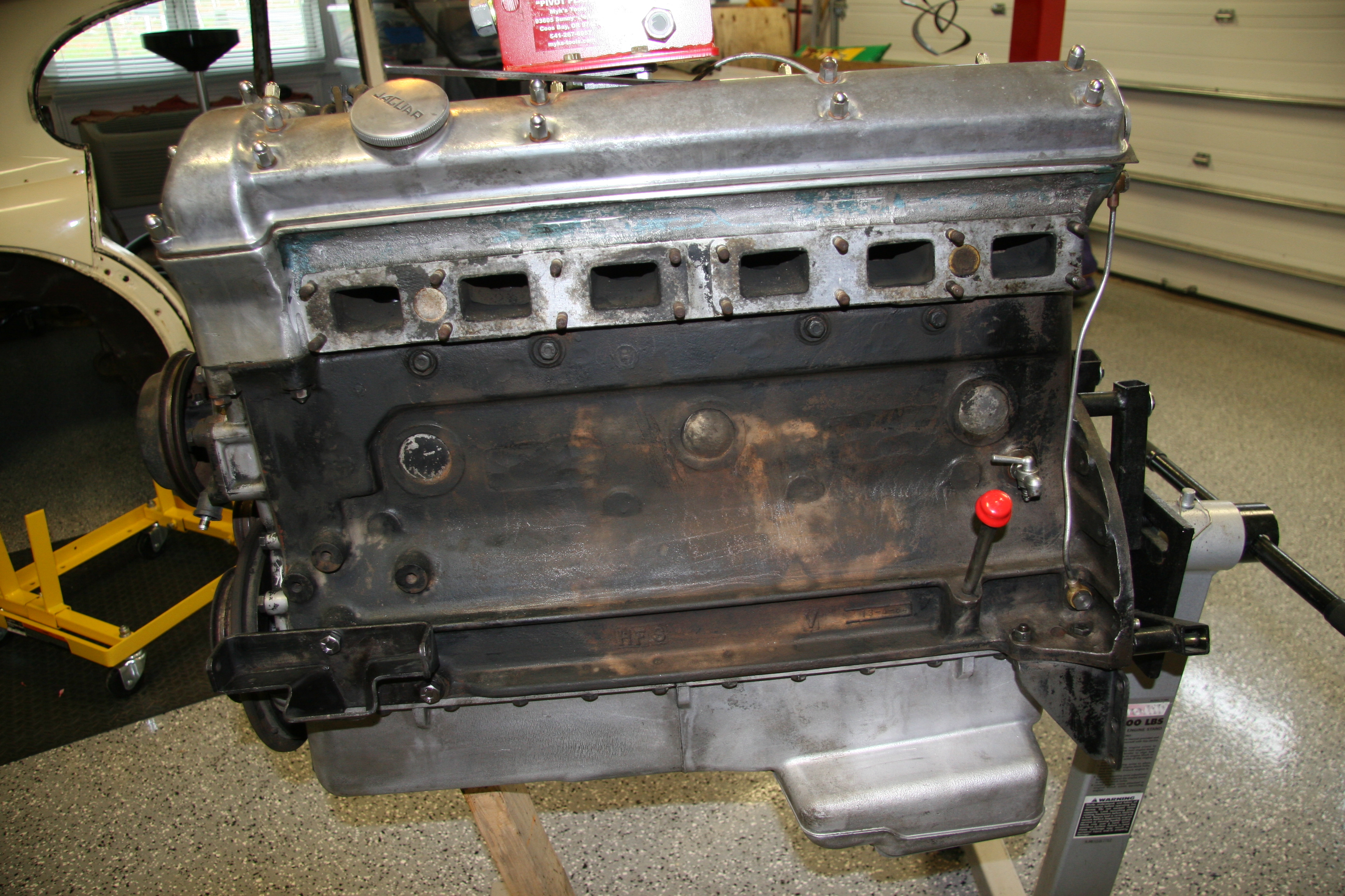
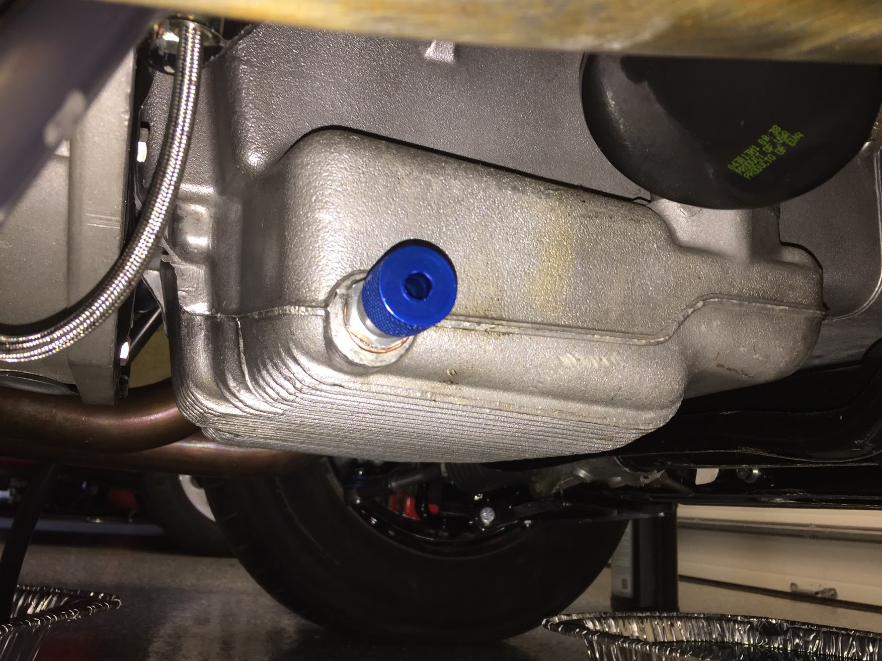
19. Breather Assembly – The breather hose/pipe for the engine originally routed to the air cleaner where the mist would be recirculated into the carburetors. In my case, I am not using the original air cleaner and I did not want to recirculate the emissions from the breather pipe to the fuel system anyway.
I chose to use a catch can manufactured by Mishimoto. The can is a very clever design.
Mishimoto Compact Catch Can
Mishimoto Compact 2 Port Catch Can
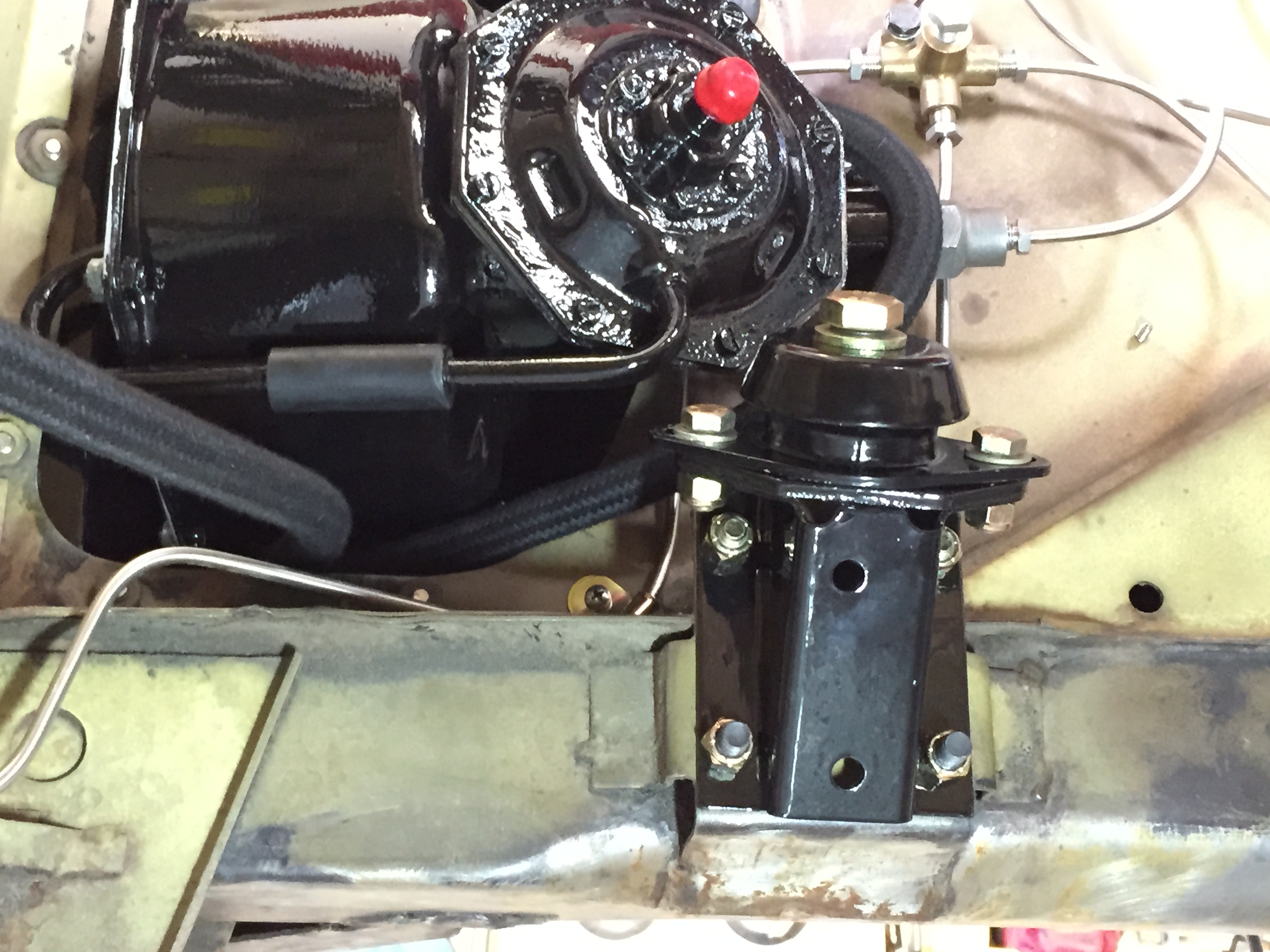
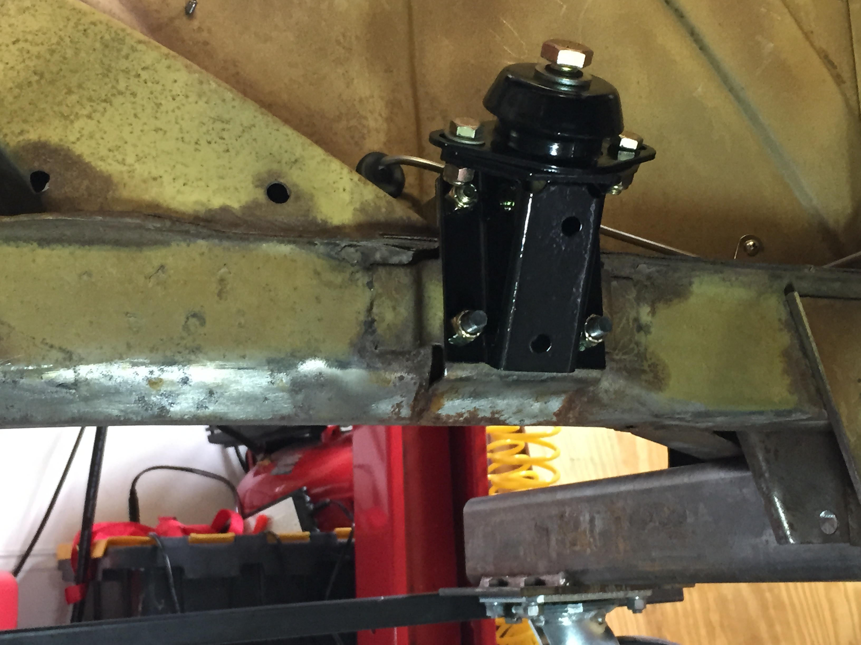
Of course, a Jaguar owner cannot have a product with a Japanese name on it visibly mounted in the engine bay, (never mind that many of the newer parts used in the restoration probably were produced in China!) so I chose to mount the can on the front suspension crossmember. At this location it is very easy to access to check accumulation. I also used a K&N Filter for the outlet port.
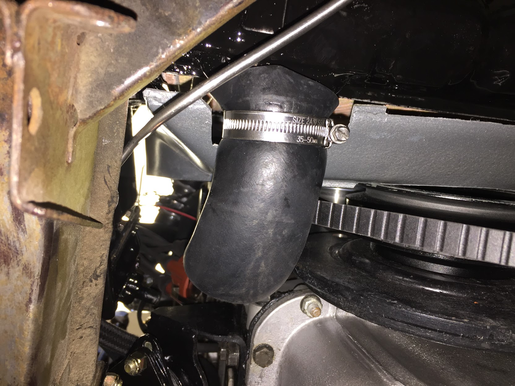
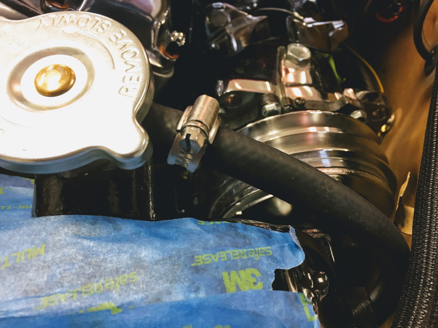
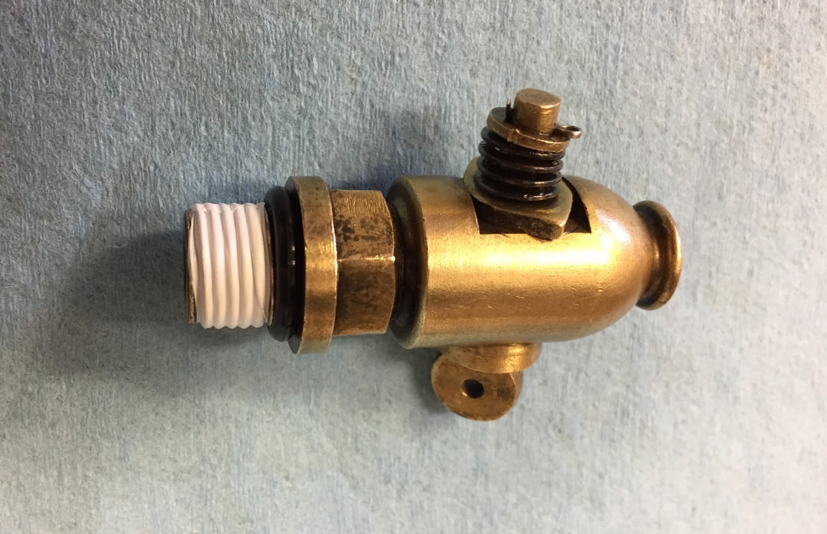
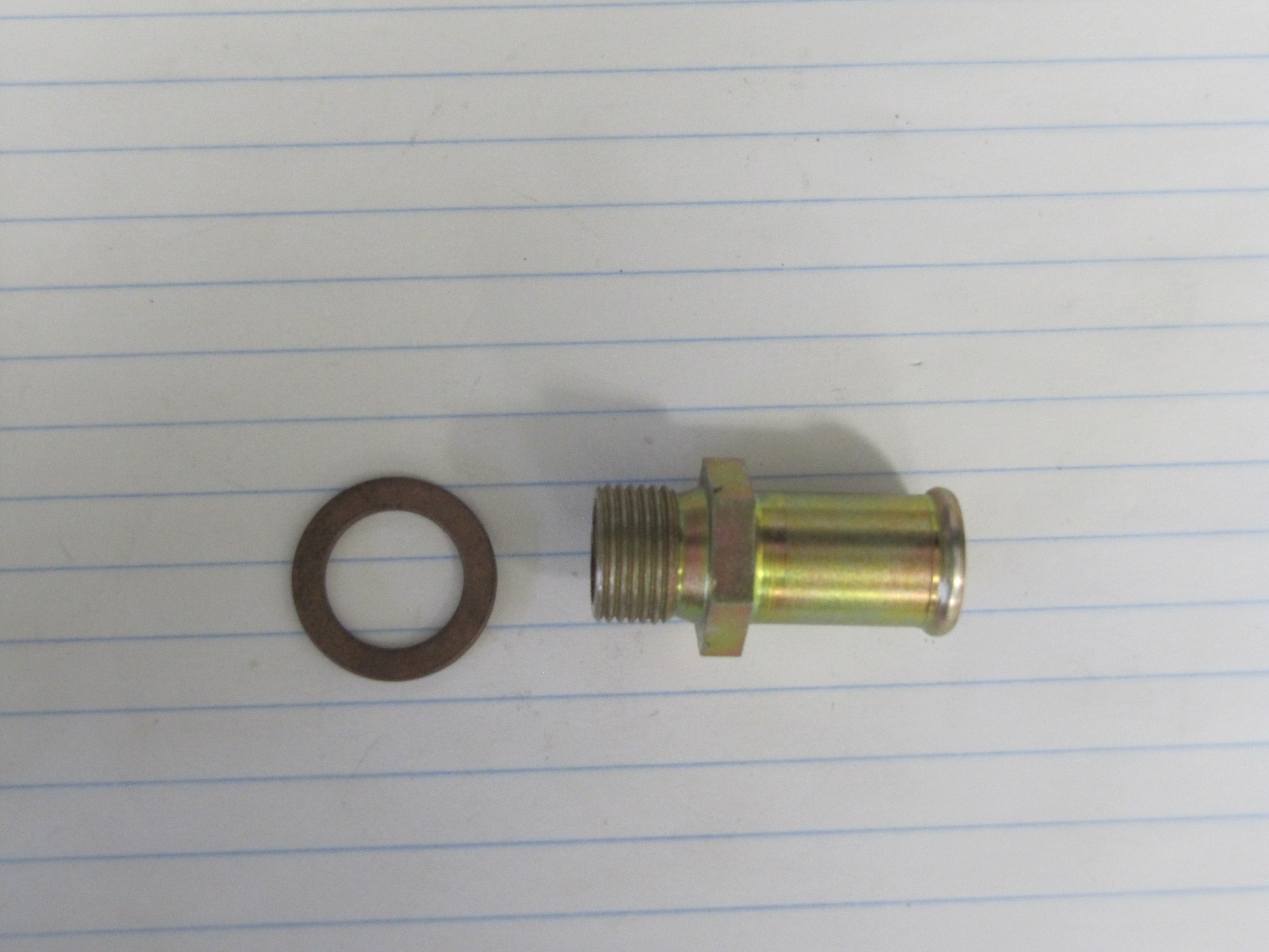
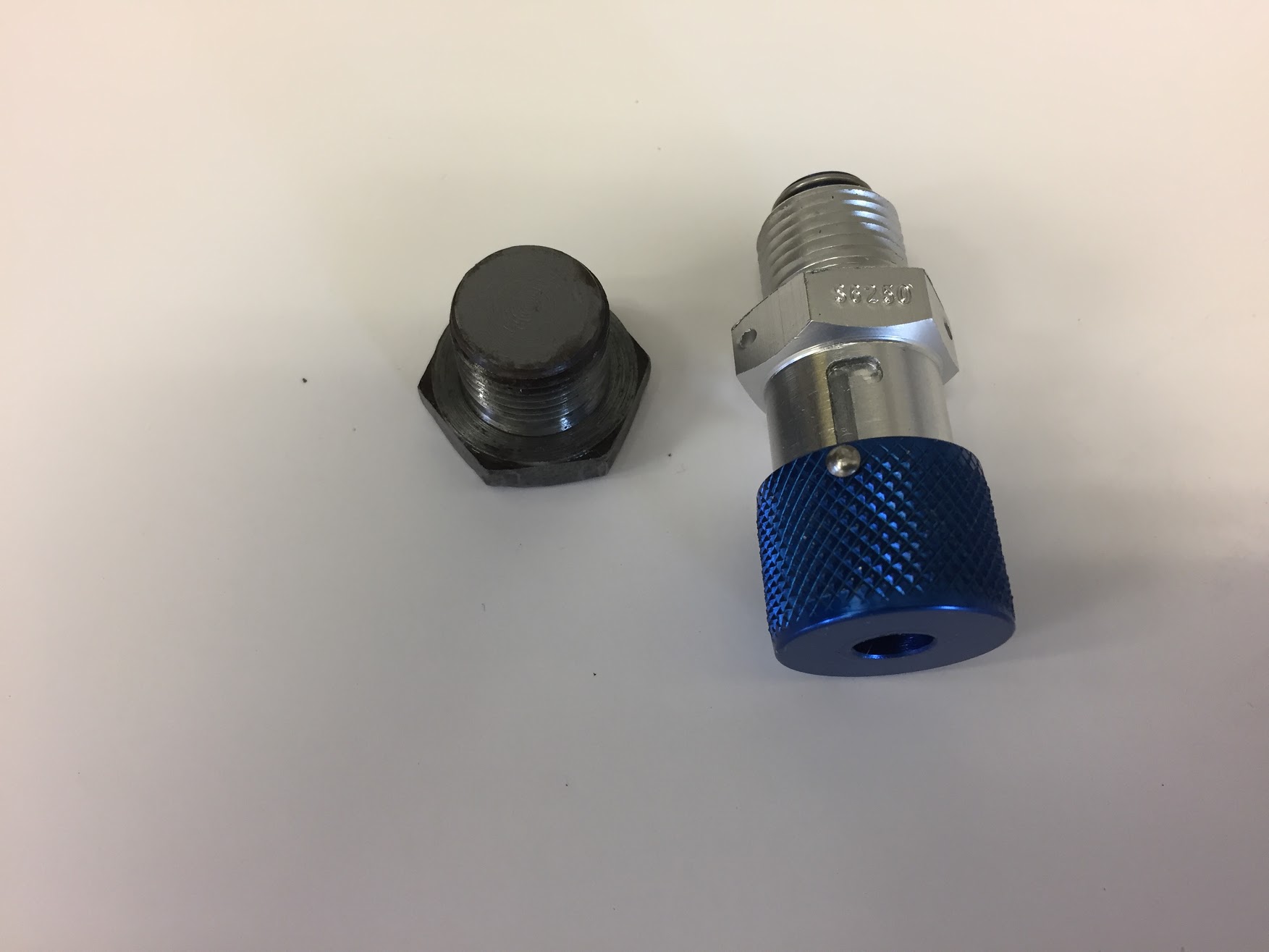
The elbow hose from the breather port on the engine is a 5/8″ I.D. but the fitting on the catch can is a 3/8″” barb so I used a barbed brass step down fitting between the 5/8″ hose and a 3/8″” hose. The straight emissions hose runs from the elbow almost straight downward, and parallel to the servo breather hose, to the catch can.
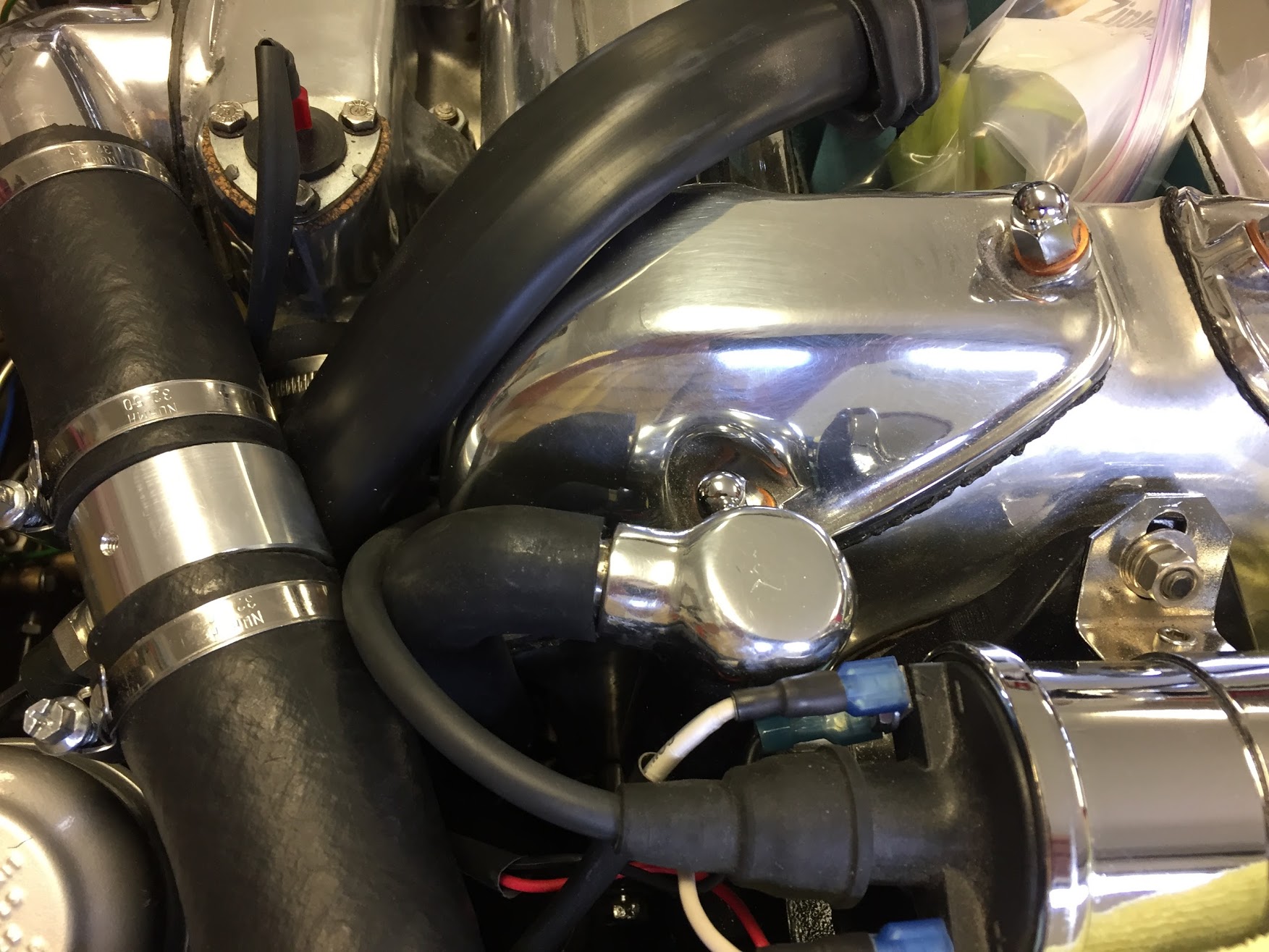
Breather Elbow Hose

5/8″ to 3/8″ Brass Step Down Fitting for Breather
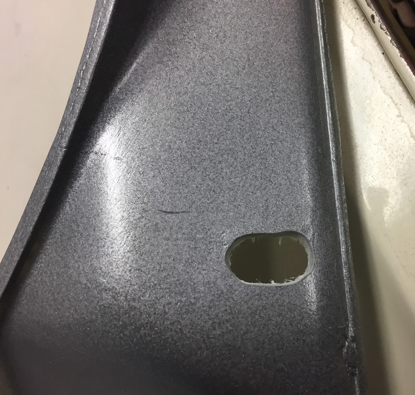
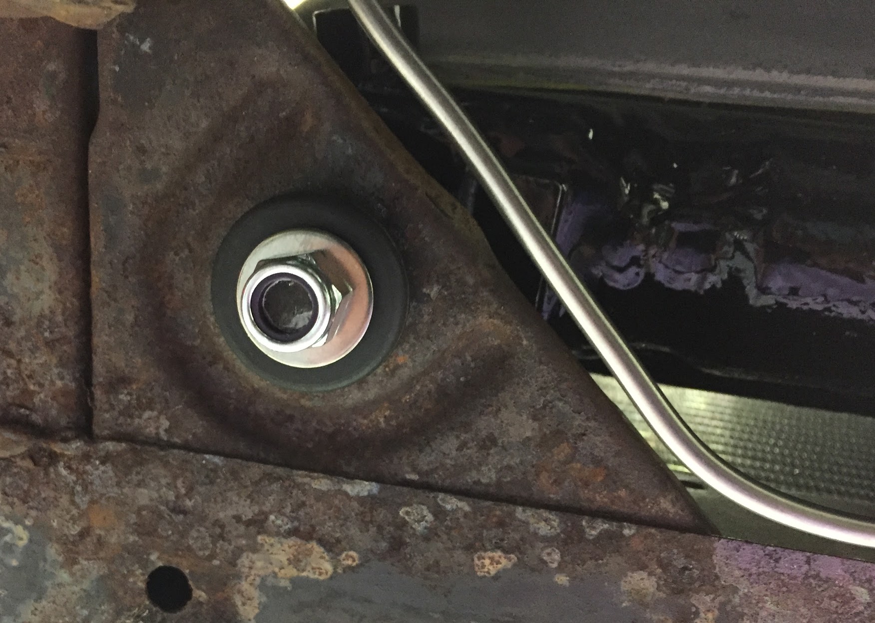
These photos are dark and it is a challenge to see the mounting of the can. I was able to use a hole that was already in the front crossmember so it was not necessary to drill any holes to mount the catch can. Always a pleasing outcome!
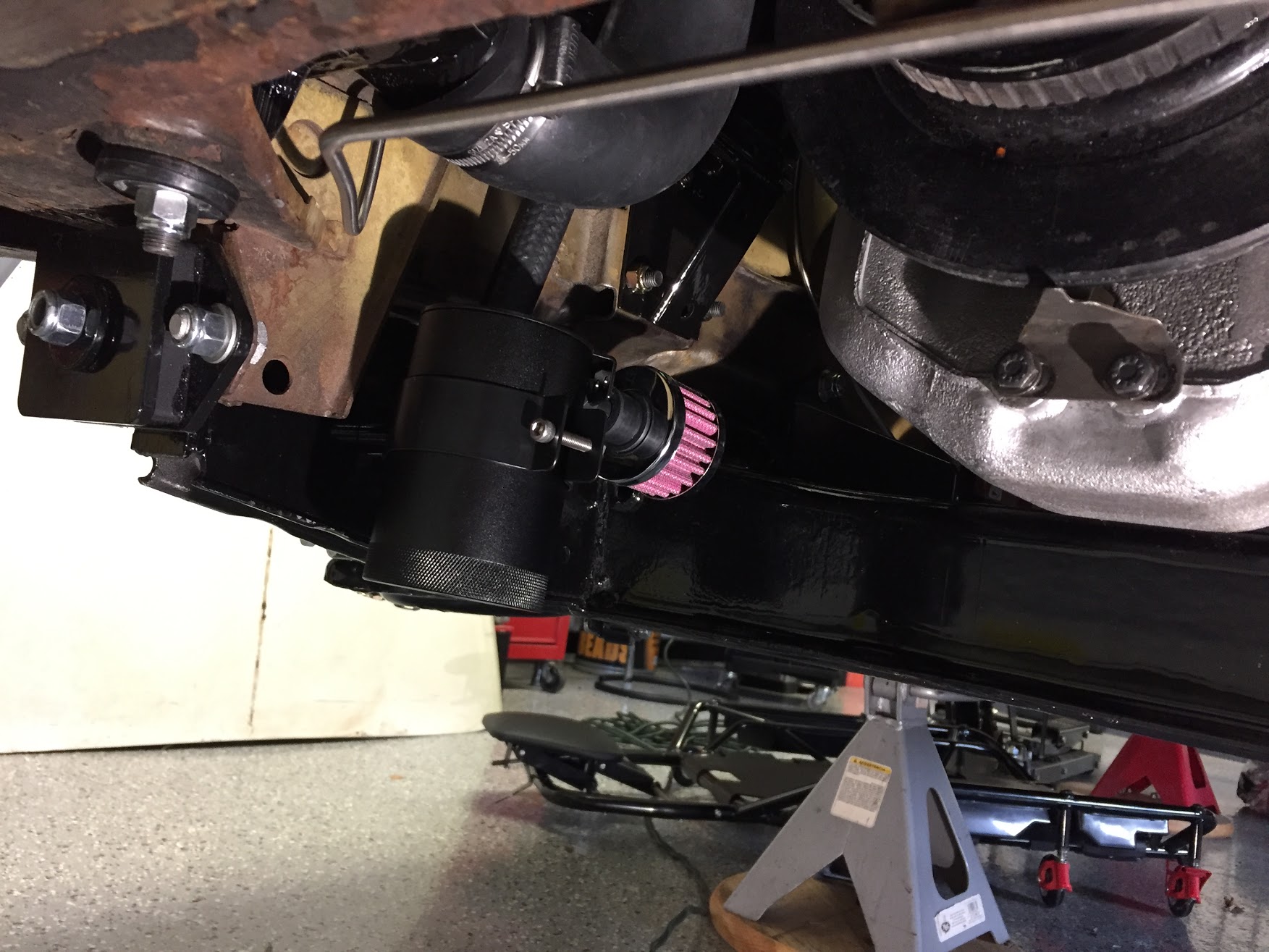
Mishmoto Catch Can Mounted on Front Suspension Crossmember
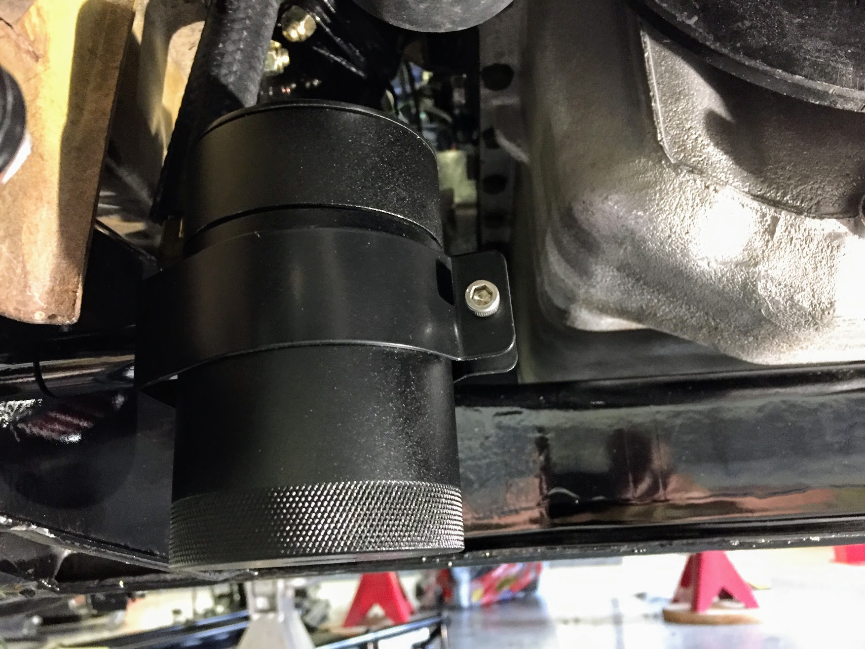
Mishmoto Catch Can Mounted on Front Suspension Crossmember
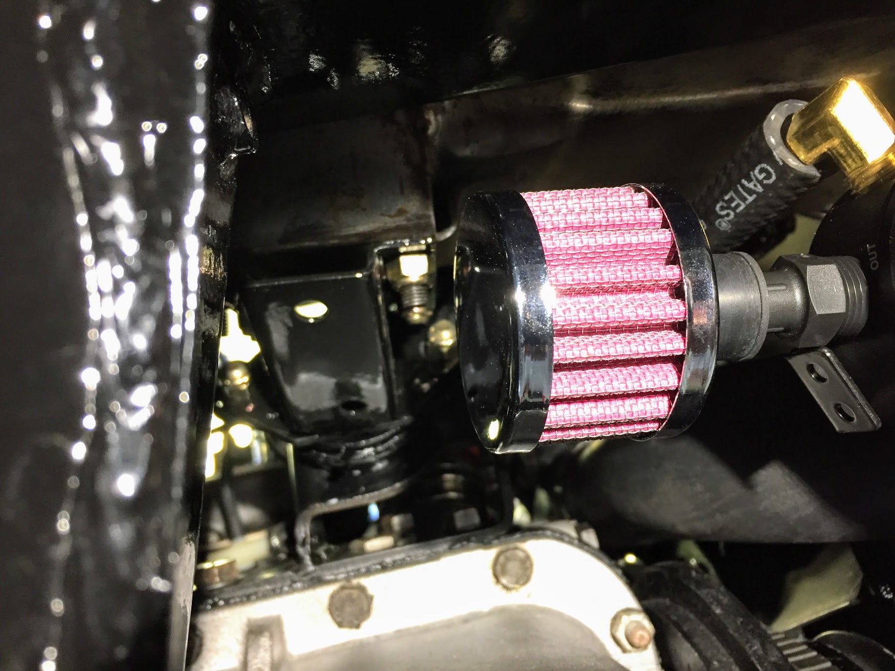
K&N Filter on Catch Can Outlet Port