Navigating The Jaguar MK2 Project Site

Site Organization and Navigation

The site for the Jaguar MK2 restoration was initially divided into three parts:

  1. Disassembly,
  2. Restoration and Fitting, and
  3. Reassembly.

However, I have removed all of the posts related to the “disassembly” phase of the project. The “restoration and fitting” or trial assembly of the renewed and new components is detailed. Major sections of work, generally following the Jaguar MK2 Models Service Manual, are journaled. I have assumed that the reader will find this approach more useful than a sequenced chronology.

I have sold this car before completion. My wife and I have downsized and relocated to Florida. Garage space is now more limited and so something had to go! Mike Gassman of Gassman Automotive in Waynesboro, VA now has the car to complete for a future owner.

To be redirected to project entries, or posts, for the Jaguar MK2 Project, just click on the burgundy rectangular navigation box in the upper right corner of this site. 

Please click photos once for larger images or twice for even larger detailed images. Images will open in a new window.

I am interested in your comments about the content and presentation, so please email me or comment on any individual entry. I will be happy to respond.

Lin

New Wiring Harness Connectors

Relay/Fuse Panel Location

As I have already indicated, my wiring harness design is very similar to Eric’s and I give him all the credit for thinking through the logic of the approach. However, we do differ in some respects.

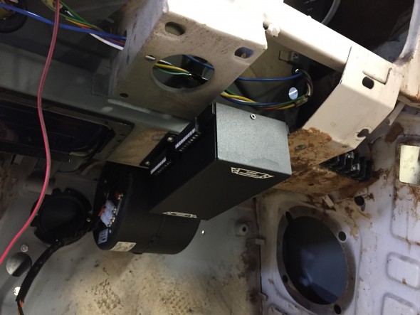
I decided to mount my Classic Technologies Relay/Fuse Panel below the right side of the dash fascia, in front of the RH passenger seat. While in this photo it appears that its location would be obtrusive, it really is not.

Mounting of the Classic Technologies Fuse Panel

Mounting of the Classic Technologies Fuse Panel

This will require the modification of the finish panel below the dash, but then that was going to have to happen anyway to accommodate the blower and vent for the air conditioning. Moving the relay/fuse panel to this location also eliminated a significant amount of wire from the engine bay.

As will be described below, the interior placement of the fuse panel also allowed me to use the original Jaguar fuse panel mounting assembly as a screen for three barrier blocks used in the engine bay for the high beams, low beams, horns, fog rangers, side lights, and ground connections.

Wiring Connections 

As has been stated previously, I am “building up” this car to the point of being able to test the electrical system, drive train, air-conditioning, power assisted rack and pinion, upgraded brakes, motor, gearbox, overdrive and etc. I will then “take it down” again for paint, and then have a final reinstall of all components. I would not do this if I was truly restoring the car, but this is a mild rest-mod and I simply feel better testing everything in advance of paint.

Although it could well be properly classified as anal, I prepared a spreadsheet of basically every electrical connection in the car. I did this to use in conjunction with wiring diagrams. The diagrams alone just don’t give enough information about wire routing that the spreadsheet affords. The spreadsheet is still a work in progress. It needs some “cleaning” and I am sure I missed a few things, but I will modify as I go and will revise the spreadsheet as changes are made. I anticipate that this spreadsheet will be helpful when I reinstall the wiring in the car after paint.

Again, a disclaimer is appropriate: The spreadsheet is provided as guidance for those who might wish to do something similar, but it should not be duplicated or utilized without careful inspection and  approval by a certified automotive electrician.

This alphabetical listing of components is provided to help quickly identify items in the electrical system. A spreadsheet line number(s) associated with the component is indicated.

Rose Jaguar MK2 Electrical Connections Alpha listing

This is the spreadsheet showing all connections:

Rose Jaguar MK2 Wiring Spreadsheet Modified 6-14-17

The Central Gauge/Instrument Panel

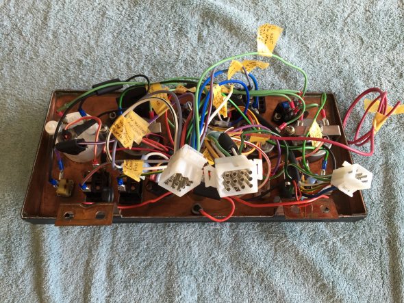
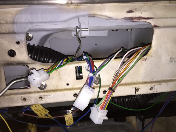
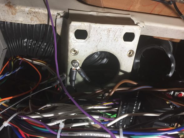
The instruments/gauges and switches included in the Instrument Panel Assembly are detailed in the post “Gauges, Instruments and Switches.” I wanted to make the panel truly modular so many of the wires emanating from the gauges and switches on the instrument panel assembly are routed through three Molex connectors. It is now possible to disconnect the three connectors and remove the Instrument Panel Assembly from the car. The wires associated with each of the Molex connectors are routed through a bracket with a large rubber grommet. From that point wires travel either through one of the ports on the firewall or to one of the barrier block terminals under the dash.

Two twelve station Molex connectors and one six station connector are utilized in my wiring plan.

Of course, the tape will disappear later and the wiring will have a little housecleaning.

Gauge Panel with Molex Connectors

Gauge Panel with Molex Connectors

Molex Connectors for Central Gauge Panel Assembly

Molex Connectors for Central Gauge Panel Assembly

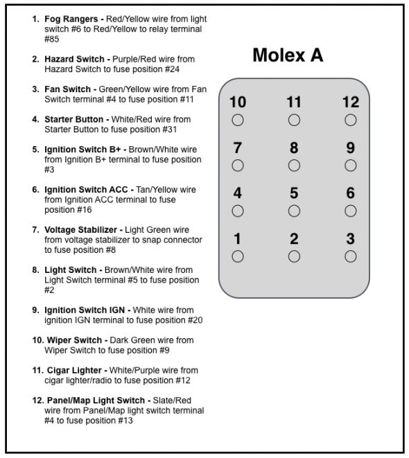
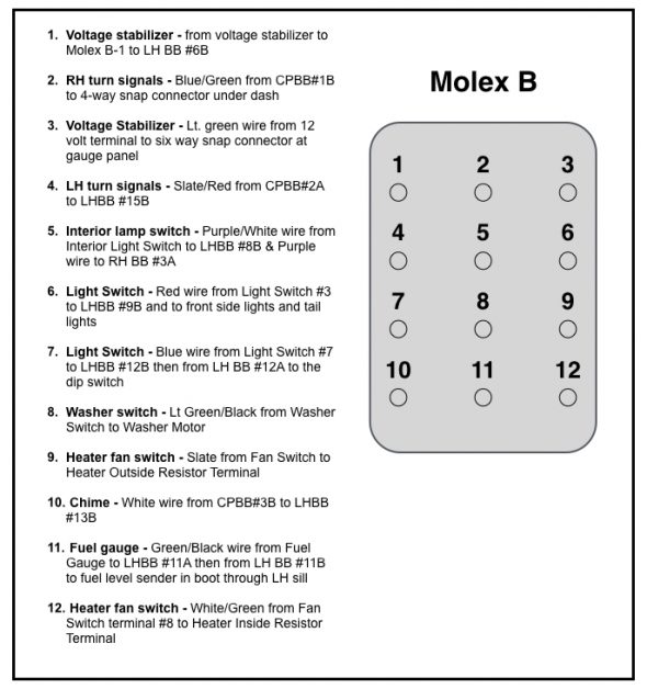
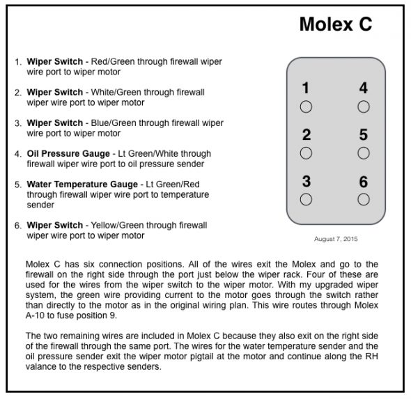
I refer to these Molex Connectors as “A,” “B,” and C.” The individual wiring connections are shown below:

Rose Jaguar MK2 Molex A Connections

Rose Jaguar MK2 Molex A Connections

Rose Jaguar MK2 Molex B Connections

Rose Jaguar MK2 Molex B Connections

Rose Jaguar MK2 Molex C Connections

Rose Jaguar MK2 Molex C Connections

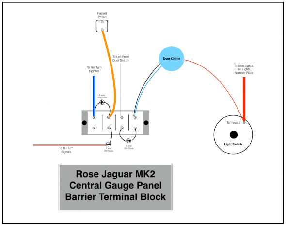
As suggested by Eric, I also used one small barrier terminal block behind the central gauge panel. This is used to accommodate our new hazard flasher system and the alarm chime to remind the driver upon exiting the car that the headlights are still on. The image below shows the eight position terminal block as originally conceived.

Jon Langley, a fellow restorer who has also elected to design his own electrical system for his MK2, pointed out that with this configuration opening any of the four doors would sound the alarm chime. So,… 

Rose Jaguar MK2 Central Gauge Panel Barrier Terminal Block

Rose Jaguar MK2 Central Gauge Panel Barrier Terminal Block

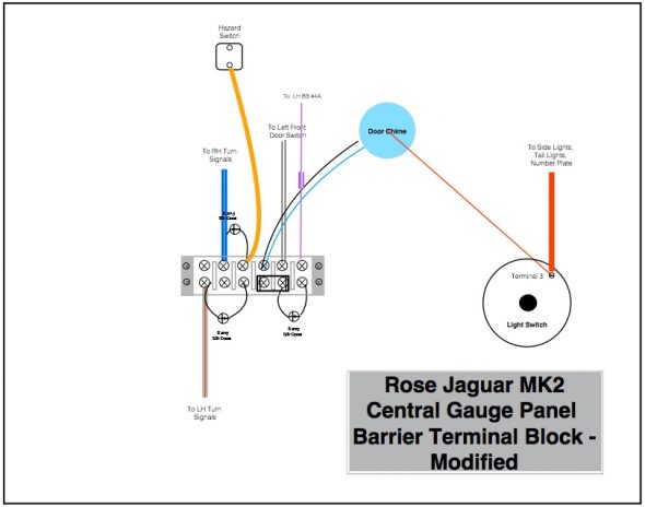
He recommended the use of a twelve position terminal block and with this modification only the driver’s door will activate the chime.

Rose Jaguar MK2 Central Gauge Panel Barrier Terminal Block – Modified


Wiring Distribution throughout the Car

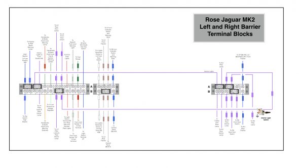
As I have already mentioned, I used barrier terminal blocks as connection points for the wiring distributed throughout the car. The LH blocks are located below and behind the steering column and the RH block is located to the right of the Classic Technologies Relay/Fuse Panel below the Cubby Box. This diagram illustrates the connection points and routes for the LH and RH terminal blocks. Clicking the image twice will make the diagram more readable!

Rose Jaguar MK2 Left and Right Barrier Terminal Blocks

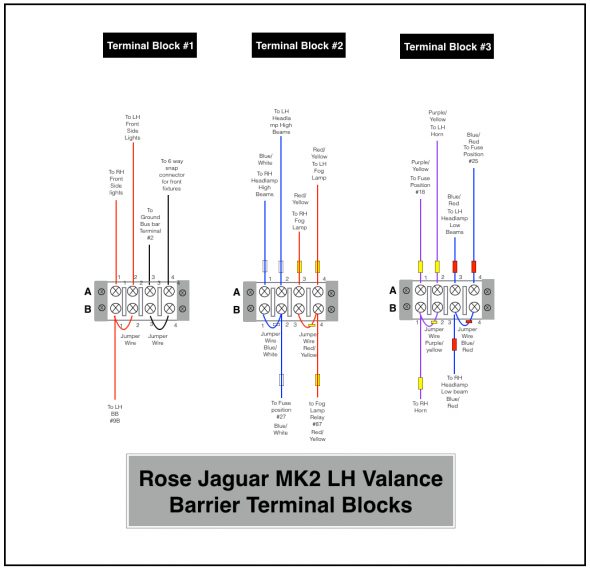
There are three 4-gang barrier blocks mounted in the engine bay on the left hand valance under the original fuse panel. Each of the blocks have clear plastic covers. They provide connection points for the headlights, with low and high beam; the Fogranger fog lamps, the horns and the side lights. The image below provides a wiring diagram:

LH Valance Barrier Terminal Blocks

LH Valance Barrier Terminal Blocks

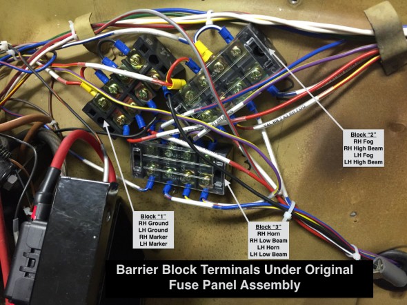
In addition, the photo below shows the three blocks installed.

Things may look a bit chaotic, but the three blocks are arranged the way they are so that they could be covered by the original fuse panel.

Barrier Block Terminals Under Original Fuse Panel Assembly

Barrier Block Terminals Under Original Fuse Panel Assembly

Of course, in my final harness the zip ties won’t be there and the wiring will be covered!

Grounding Bus Bar

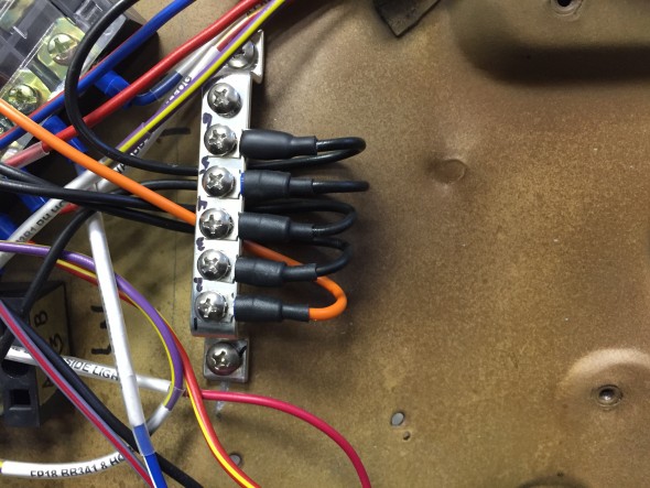
To try to bring some order to the ground connections required by various components in the electrical system, I used bus bars with six terminal mounts in four locations throughout the car. There is one bus bar on both the LH and RH engine bay valance as well as one under the steering column and one under the console on the transmission/propshaft tunnel. These eliminated the need for individual ground connections scattered about the car.

This will provide for much easier tracking of ground connections.

Ground Bus Bar

Ground Bus Bar


Doors and Windows

Doors and Windows

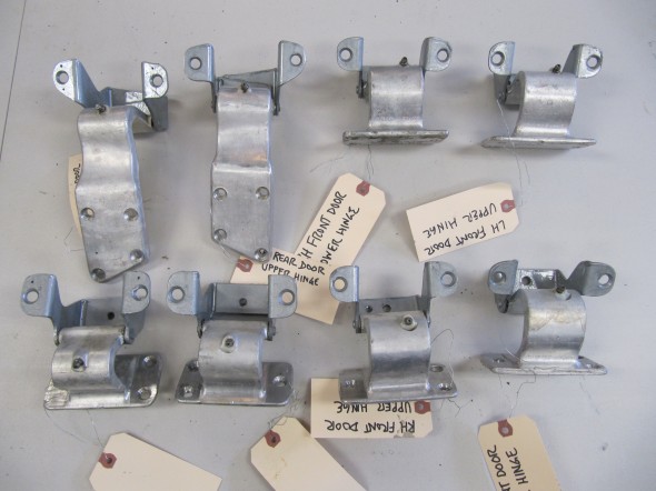
Door Hinges

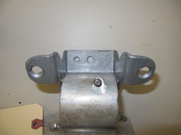
I decided against removing the hinge pins to “restore” the hinges. All the hinges were free moving but nice and tight with no discernible excess play. The door side of the hinge is aluminum while the body pillar side of the hinge is unpainted steel. It appeared that the hinges were painted while mounted on the car.

I removed the paint with paint remover, painted the bare metal side of the hinge with silver POR-15 (since I was leaving the hinges assembled, I could not zinc or cad plate the bare metal pieces), greased the hinges and tried them all for good fit with new bolts and screws sourced from SNG Barratt.

All of the adjustment in the door hinges is on the door side mounting. The hinges are fixed in place by captive nuts in the “A” and “B/C” pillars.

The hinges are now ready for assembly to the car when the time comes.

Cleaned Door Hinges

Painted with POR-15 Silver

Door Check Arm Assemblies

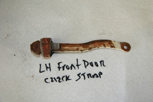
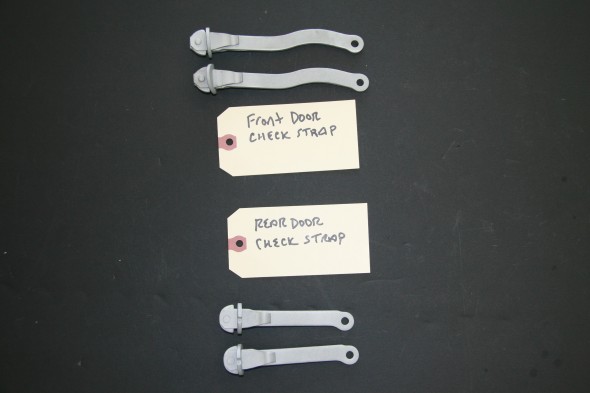
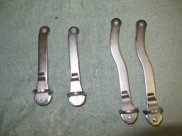
Each door has a check arm with a rubber buffer. The rubber buffer or stop is not available from the typical sources so I search for a suitable replacement material to use. I was unable to find anything that had the fabric rubber combination in the original stops. I media blasted each check arm and will have them zinc plated.

LH Front Door Check Arm Assembly

Front and Rear Check Arm Assemblies

Rezinced Door Check Straps

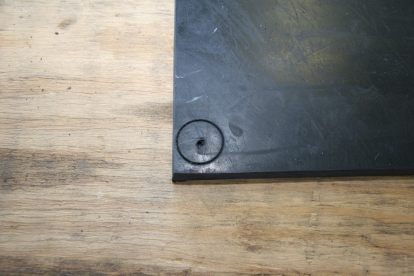
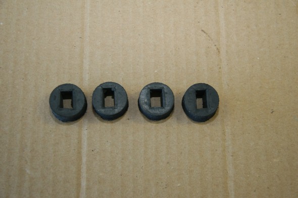
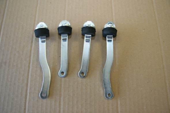
I ended up purchasing a 1/2″ thick Neoprene pad from Grainger and cut out the stops with a 1 1/8″ hole saw in my drill. Then using a 3/8″ and 5/8″ chisels I cut out the rectangular opening in each rubber stop. I will coat the circumference of the rubber with black silicone to provide some protection from moisture. I tried the stops on the check arms and installed one of the rear door check arms with the stop in a door. Everything seems to work well. Hopefully the new neoprene stops will hold up.

One and one eighth inch hole saw cut in half inch neoprene

Neoprene Rubber stops for Door Check Arms

Front and Rear Door Check Arms with Neoprene Rubber Stops

I am not yet at the point where I am ready to install door seals; however, I came across some photos and installation instructions on the Jag-Lovers web site that may prove helpful later. This is a link to the page:

http://www.jag-lovers.org/snaps/snap_view.php3?id=1354948688

Door Hinge Shims

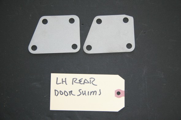
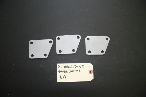
The rear doors had hinge shims on the upper hinges. The LH with two shims and the RH with three. I media blasted the hinges and will then zinc plate them. All of the shims were the same thickness.

LH Rear Upper Shims

RH Rear Upper Shims

Installing the Mk2 Doors

I knew from other car restorations that door mounting is never fun, nor easy. I decided that I would practice mounting the MK2 doors a couple of times before doing the real thing after fresh paint had been applied!

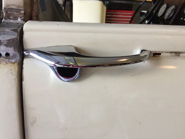
First, I installed the exterior door handles on each door, because these become impossible or nearly impossible to access once the windows and there frames go into place. Additionally, this gives the person holding the door for mounting something comfortable and convenient to grasp while holding the door. Each handle has two #10-32 mounting studs with a flat washer, shakeproof washer and nut. The front of the handles had what appeared to be leather or fiber pads between the handle and the door when I removed them from the car. I replaced these with neoprene pads that I cut to shape. Once finally mounted, these can be cut to shape with a sharp razor knife.

Exterior Door handle with Neoprene Cushion

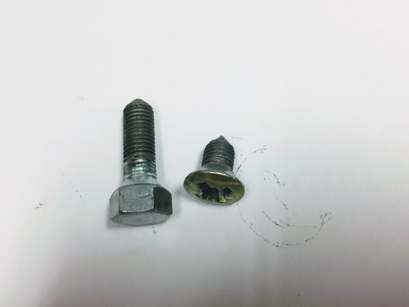
After wrestling with the door installation quite a bit, I finally concluded that the best approach is to first, bolt the hinges to the doors with the bolts barely started in the captured threaded plates. Then lift the doors to the car ( a second person, or a special purpose jack designed for the job, is particularly helpful here!) and then start the pozi-drive screws through the hinges into the “A” pillar or “B/C” pillar. Again, everything its barely started, nothing tightened. After all of the pozi-drive screws are mounted, it is then time to install the 5/16-24 x 1 hex head bolts through the center of the hinges into the pillars. The front door hinges also have the two 5/16-24 interior lights switches that need to be started and these are located in the center of the lower hinges.

Door Fasteners

After all of the fasteners are started, it is then a matter of tightening the screws and bolts until they start to “hold” the door, but with adjustment (movement) still possible. Door gaps can then be manually sorted until you end up with what you want. This is a slow process requiring patience. I did all of this without the lock strikers installed. To simulate where the rear shut lines should be I rolled up some tape and then taped it to the door jam to buffer the closing of the door – the job that the seals will ultimately do.

Once the doors are where you want them, the door strikers can be installed. On my car, each of the door strikers had a shim. The strikers have quite a bit of adjustment and like the doors require a fair amount of “fiddling” until you end up with a door closure that you are happy with. More information about the door handles and locks can be found in this post: https://valvechatter.com/?p=6027

Window Regulator Installation

The front and rear regulators are different designs but the same procedures for installation apply. I found it easiest to compress (by turning the winding crank) the mechanism to its smallest size. Insert the mechanism into the door and then crank the winder the other direction to spread the regulator and align it with its mounting holes in the door. One can then loosely start the mounting screws to support the mechanism in the door. This process is best demonstrated in a video. The is the installation in a rear door of the Jag.

It is a fairly easy process once you get the hang of it.

As shown in the video, and in the image below, the rear door regulator mounts with six slotted 1/4″-28 x 5/16″ pan head machine screws.

LH Rear Door Window Regulator Mount and Lock remote Control

While the front door regulator mounts with four slotted 1/4″-28 x 5/16″ pan head machine screws as seen in the image below:

RH Front Door Regulator Mount with Four Screws

And, the spring/crank end of the regulator on the front door also mounts with four slotted 1/4″-28 x 5/16″ pan head machine screws:

RH Front Door Regulator Spring Mount with Four Screws

LH Front Door Window Regulator with all eight Mounting Screws

Installing Window Glass and the Window Frame

Before the window frames are installed, the four clips securing the weatherstripping to the interior side of the outside edge of each door need to be  pushed onto the door. The image below shows the clips when I removed the window frames from the car:

Four Clips to Secure Weather Strip to Outer Door Edge

This image shows a section of the the weatherstripping in place and secured to the mounting clip:

Door Weather Strip and Mounting Clips

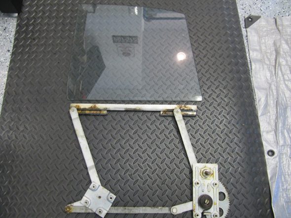
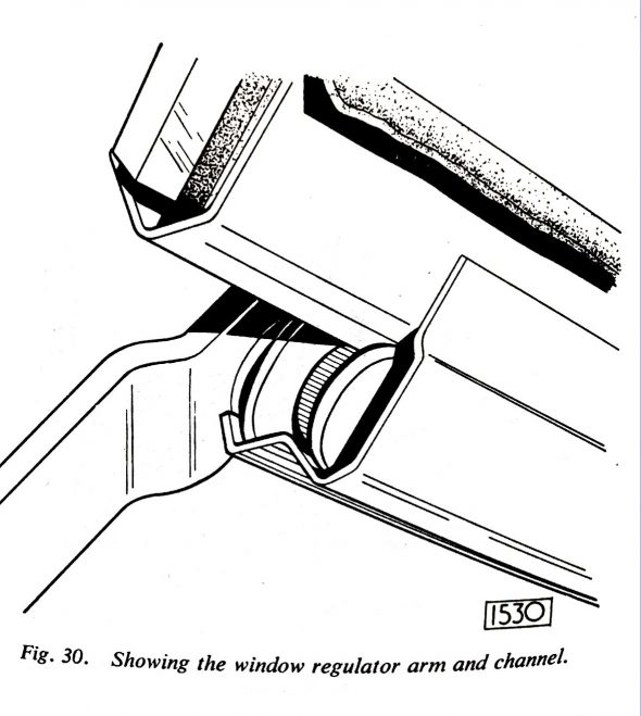
The image below shows a front window glass with the regulator “wheels” in the window channels 

Front Window Glass and Regulator

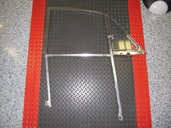
The image below shows a front window frame with the lower mounting points on the legs of the frame:

Front Window Frame

This process is also best described with a short video:

With the front window the procedure is the same except that the tracks are initially in front of the regulator rollers and one pushes the window rearward to advance it onto the rollers. This graphic shows the window frame sliding into the regulator:

Window Mounting to Regulator

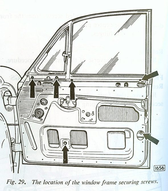
The Service Manual has a nice graphic illustration that shows the window frame securing points once you have the frame positioned in the door.

Window Frame Securing Screws

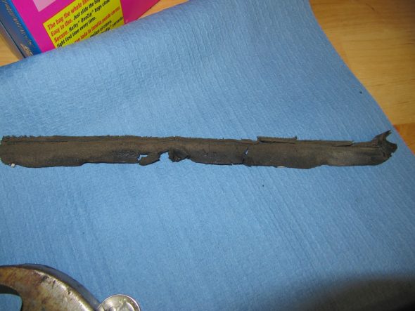
Before the window frames are secured to the doors, the Service Manual indicates that a layer of sealing compound should be placed on the door frame just below the  front and rear ventilators. I refer to this material as dum-dum made by 3-M. I will use a home made rubber gasket probably combined with dum-dum to help seal the area and keep water out. This is an example of what I found upon taking the window frames out of the car:

Dum Dum Sealer Below Window Frame

Dum Dum Window Frame Sealer


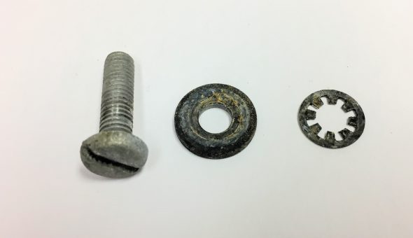
Each of the four door window frames is secured at the top of the door with four slotted #10-32 x 3/4″ pointed pan head machine screws. The mounting points for the rear doors are slightly different than the front doors as shown in the graphic, but all doors use the same number of screws. The window frames can also slightly slide rearward or forward for proper fitment. These screws should be loosely fitted to the door and window frame, but not tightened yet.

Window Frame Mounting Screws #10-32 x 3/4″

Front and Rear Adjustment of Window Frame

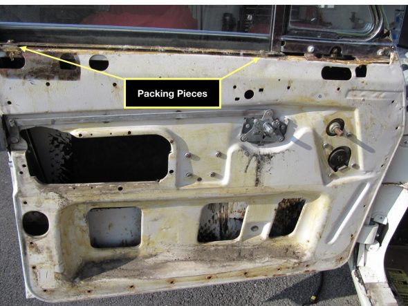
The height of the window frame is adjusted with the insertion of special shims, or packing pieces as they are called in the Service Manual, as needed. On my car, two sizes of shims were used. 

Window Frame Mounting Shims

Window Frame Packing Pieces

LH Front Door – Rear of window used one packing piece; the front of the window used two packing pieces of different sizes.

RH Front Door – Rear of window used two packing pieces of the same size; the front of the window used two packing pieces of different sizes.

LH Rear Door – Rear of window used one packing piece; the front of the window used one packing piece.

RH Rear Door – Rear of window used one packing piece; the front of the window used one packing piece.

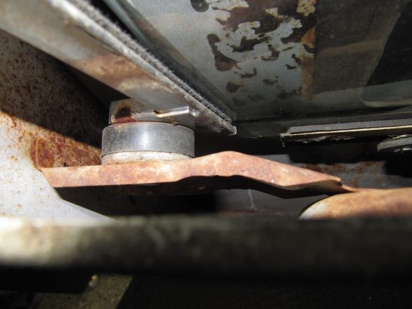
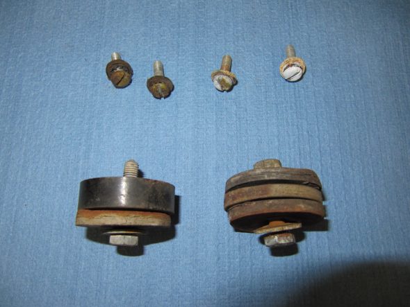
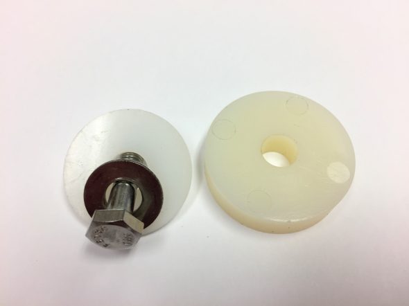
Once the window frame height seems to be right, the two lower securing points are fastened with a single 1/4″-28 x 1-1/4″ hex head bolt with a serrated washer and plain washers. Originally wooden discs or “packing pieces” were used at the lower leg fastening points to tilt the top of the window frame inward toward the rubber door seal. My car actually had a combination of wood and some hard rubber packing pieces. My wooden packing pieces were deteriorated and I will be using 1-1/2″ diameter nylon spacers with 1/4″ diameter center holes as replacements.

Once the window frame is in the proper position front to back ( “The window frame should clear the front screen pillar by 1/16”), the Service Manual instructs that the window frame post lower mount, with its packing pieces, farthest away from the door hinges should be tightened first. Then refit and tighten the front lower mounting point. Finally tighten the four pan head screws at the window frame top mounting points.

Original Window Lower Packing Pieces and Mounting Point

Original Window Frame Upper Mounting Screws and Lower Spacers with Bolts

Modern Window Frame Lower Spacers and Mounting Bolts

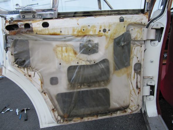
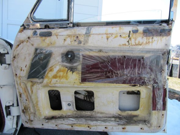
After the regulators, window glasses, window frames, weather stripping, and sealants are installed and the frames are properly adjusted the next to last step of the process will be to reinstall vinyl around the doors moving parts and to apply plastic sheeting to keep water inside the door and not in the interior! These photos show the original application:

Rear Door Plastic Sealer Sheet, Vinyl Anti-rattle Cushions

Front Door Plastic Sealer Sheet, Vinyl Anti-rattle Cushions


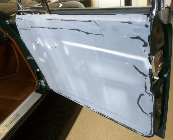
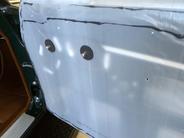
Eric Kriss provided an excellent explanation of this process on his Jaguar MK2 Restoration site. http://fairislepress.com/WP/?p=10706 He suggests that Jaguar placed the vinyl protectors to keep the window and door lock mechanism from fouling the plastic sheet. As Eric did, I will make some new ones using the old as patterns and glue them to the doors. Eric used a 4 mil plastic sheet with 3M 08621 Window-Weld 5/16″ Round Ribbon Sealer to fix the plastic sheets to the doors. Having used this material before I know that it is pliable, very sticky and reversible. Eric applied the ribbon sealer to the door and then pressed the plastic sheet to it using a rubber roller. I will do the same. This is a photo taken from Eric’s site: 

Eric’s Door Plastic Seal Sheet

The next step is to install the foam rubber cushions that fit to the window cranks and door handles before the casings go on. Again, this photo is from Eric’s site.

Foam Rubber Buffers at Handles

Finally, it is a matter of installing the door trim casings and the window crank handles and the door handles.

I will post more about this later. But for now I just want to record that it looks like I will need about 75″ of window channel track felt for each of the rear door windows and about 80″ for each of the front door windows.


Remote Control Door Locks

Particularly since the MK2 is a four door sedan (saloon) I want to add the modern convenience of centrally operated electric door locks and while I am at it I might as well add a keyless entry feature.

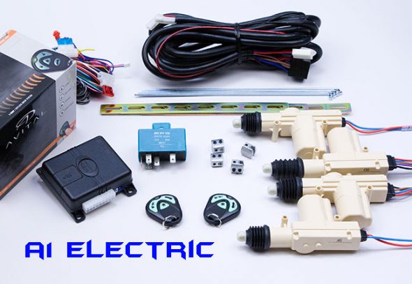
These kits are quite inexpensive and I purchased mine from A1 Electric. https://www.a1electric.com/Merchant2/merchant.mvc?Screen=PROD&Store_Code=AEOS&Product_Code=W02F-712T This kit includes most everything that is needed. The locking part of the kit is advertised as being Swiss made.

This is an image of the contents of the kit:

W02F MES Central Door Locking Kit with Keyless Entry

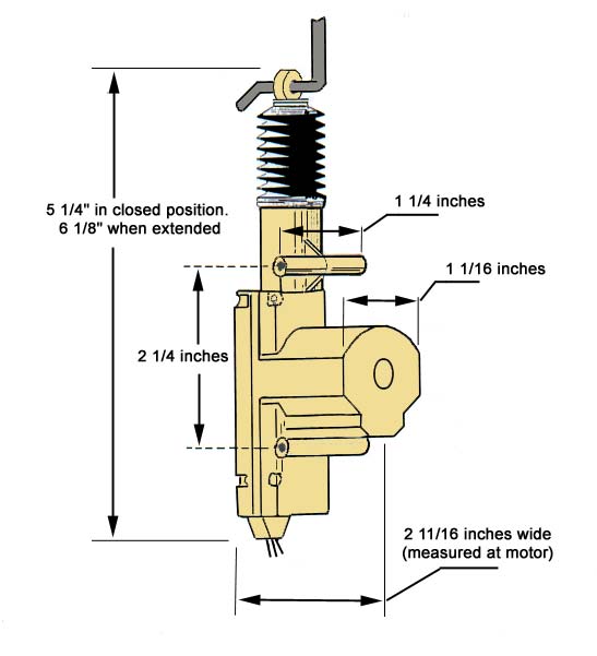
This image illustrates the dimensions of one of the actuators:

Actuator Dimensions

These are the installation instructions provided with the kit:W01F & W02F MES Central Door Locking Kit Installation Instructions

Mounting the Actuators to the Rear Doors

I began the installation of the four lock actuators with the RH rear door. Because the door window and lock hardware were not mounted to the door, I first installed these components. I did so to be sure that the actuator did not conflict with the operation of the window. Information on the installation of the window and lock components is provided in the “Door Handles and Locks” website entry https://valvechatter.com/?p=6027 and the “Doors and Windows” website entry https://valvechatter.com/?p=5485

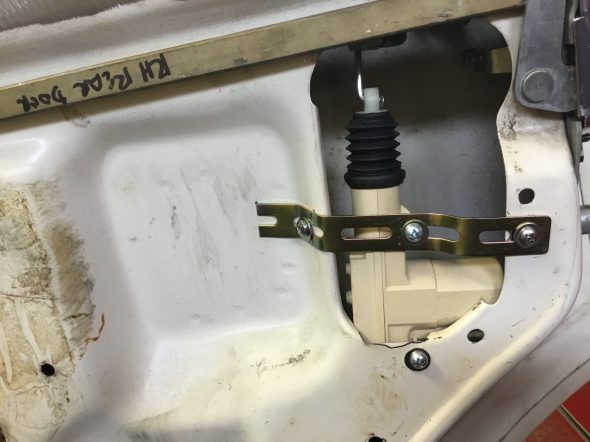
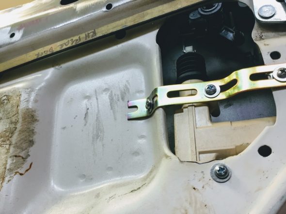
The kit incorporates mounting hardware including a yellow zinc bendable strap and the necessary screws. These images show the location of the rear door actuators (both doors are the same).

Lock Actuator RH Rear Door

Lock Actuator RH Rear Door

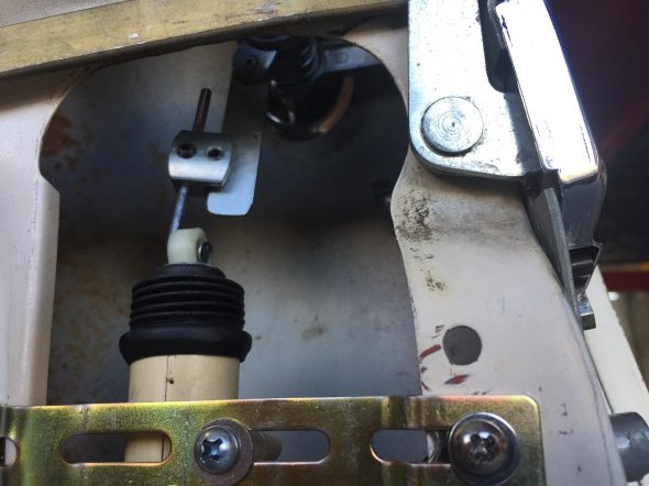
It was necessary to drill three holes in the door: two for the strap and one for the actuator body.

Connecting the Actuators to the Rear Door Locks

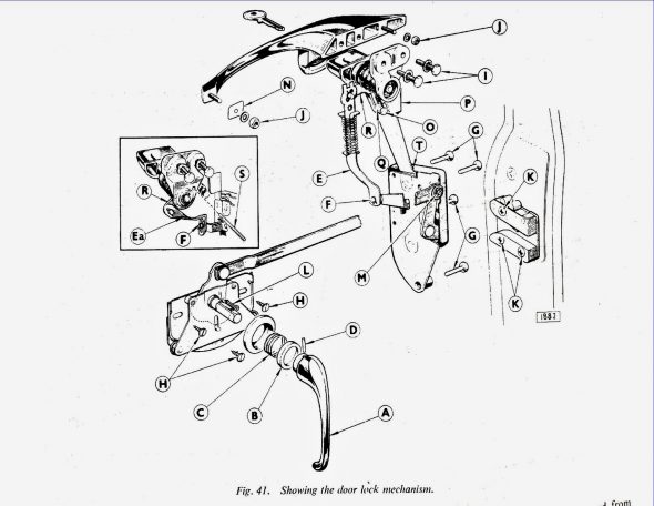
Connecting the actuator to the door lock is not difficult, but it is a little complicated to explain. The schematic diagram provided in the Service Manual on page 450 N.24 is helpful.

Jag MK2 Door Lock Mechanism Schematic

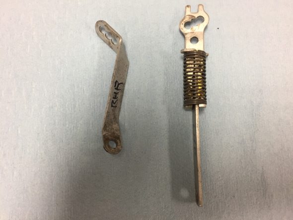
While most of the mechanism for the front and rear door are the same, there are some distinctions. The rear door components are shown in the small enclosed box in the diagram above. The connecting link (E) with a spring in the diagram is for the front door and the connecting link (Ea), without a spring, shown in the box and in the image below is for the rear doors.

Lock Connecting Links Front and Rear

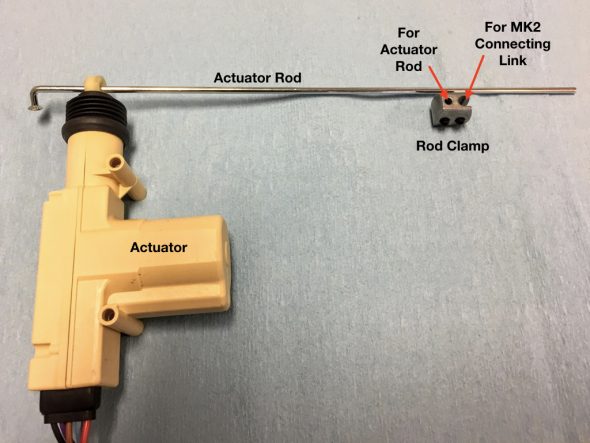
These connecting links do what their name implies: they connect the door handle locking mechanism and the remote control to the door lock and striker plate.I use the connecting links for both front and rear doors to connect the actuator rod, supplied in the kit, to the car’s locking mechanism. This is accomplished through the use of a small rod clamp that is provided in the kit.

Actuator Rod Clamp

The clamp has two set screws – one to attach the block to the connecting link (The factory lock rod in the diagram) and the other to connect to the actuator’s rod.

Actuator, Actuator rod and Rod Clamp

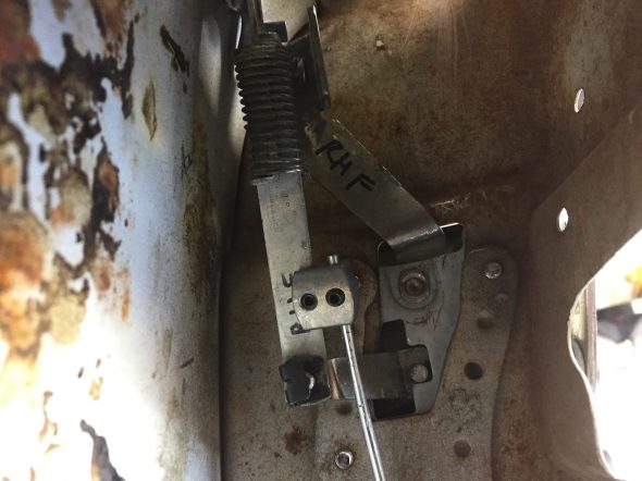
For the rear doors, to facilitate connection of the components without interference with the window frame, I chose to disconnect the connector link at the dowel (F) shown in the diagram at the top of the page. This will mean that the rear doors will not be locked and unlocked using the door handles which is of no matter to me since the actuators will be doing the job.

I then straighten the connecting link (removed the bends) and used it for the new connection to the connector block. To make the connection, the Actuator Rod needed to be bent slightly.

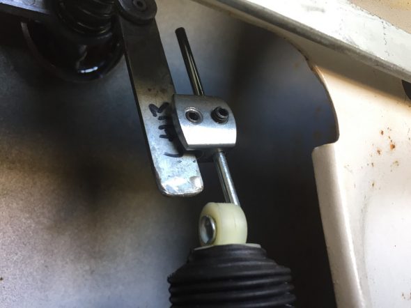
After installing the actuators in both rear doors, I tested them with a power source and was satisfied that they both operated effectively. The photos below show where the rod clamp attaches to the rod and to the connecting link. The position will be important when final assembly occurs.

LH Rear Door Lock Connecting Link

RH Rear Door Lock Connecting Link Position

Mounting the Actuators to the Front Doors

Because the door window and lock hardware were not mounted to the door, I first installed these components. I did so to be sure that the actuator did not conflict with the operation of the window. Information on the installation of the window and lock components is provided in the “Door Handles and Locks” website entry https://valvechatter.com/?p=6027 and the “Doors and Windows” website entry https://valvechatter.com/?p=5485

The front doors are a bit more of a challenge when contrasted with the rear doors.

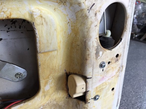
To keep the actuator in a vertical position, I decided to open a hole in the door interior face. The hole can be seen in the following image:

RH Front Door Modification for Actuator


As with the rear door actuators, the front actuators are mounted to the door with two, kit provided,  1″ self tapping screws.

Connecting the Actuators to the Front Door Locks

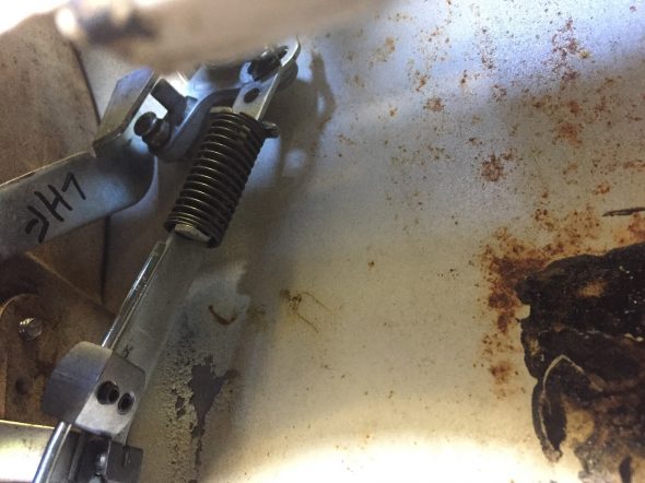
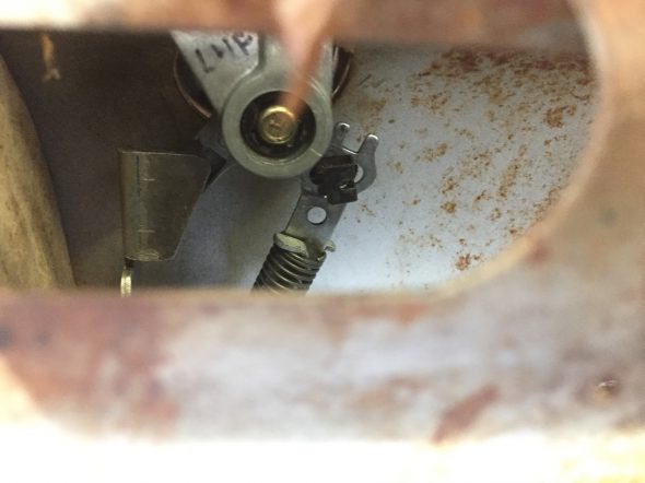
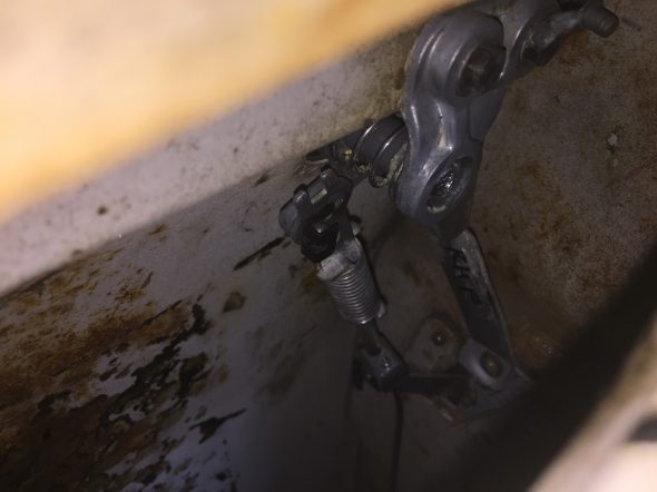
Unlike the rear doors, I want to use the interior door handle to activate the lock/unlock mechanical mechanism so I kept the original connecting link secured to the lever on the dowel on the door lock (F) in the schematic above. As suggested in the Service Manual I mounted the connecting link in the center position. But, after some experimentation. I found that the most forward position of the three worked best in my case. The photos below show where the rod clamp attaches to the rod and to the connecting link. The position will be important when final assembly occurs.

The kit directions make the following point: The alignment of the front door actuators (5 wire) on the MES lock kit is very important to proper operation. If the actuators are not properly aligned and centered it will cause the system to rapidly lock and unlock the doors or not allow you to lock or unlock the doors.

LH Front Door Lock Connecting Link

LH Front Door Lock Connecting Link Mounting Position

RH Front Connecting Link Mounting Position

RH Front Door Lock Connecting Link Forward Mounting Position


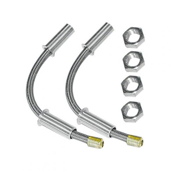
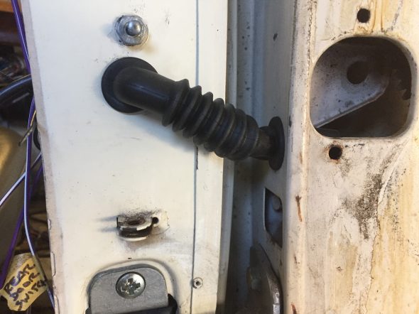
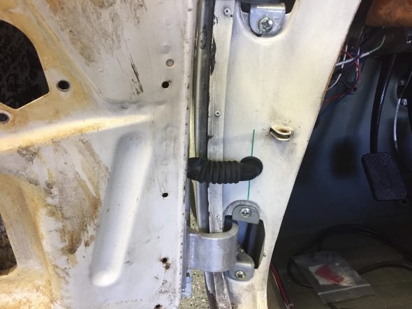
It is necessary to drill holes in the “A” pillar, the rear face of the “B/C” pillar and in the face of each of the doors to facilitate the travel of the electrical wiring for the operation of the actuators. To protect the wiring and to yield a finished look, some type of wiring loom or boot is needed. I searched for some time trying to find a product that I liked. Hot Rodders often use a stainless loom such as the pair in the image below:

Stainless Door Wiring Loom

In reality, these are quite large and in my opinion just don’t look proper on the Jaguar. I was also concerned about these making a rubbing noise inside the doors when they were operated.

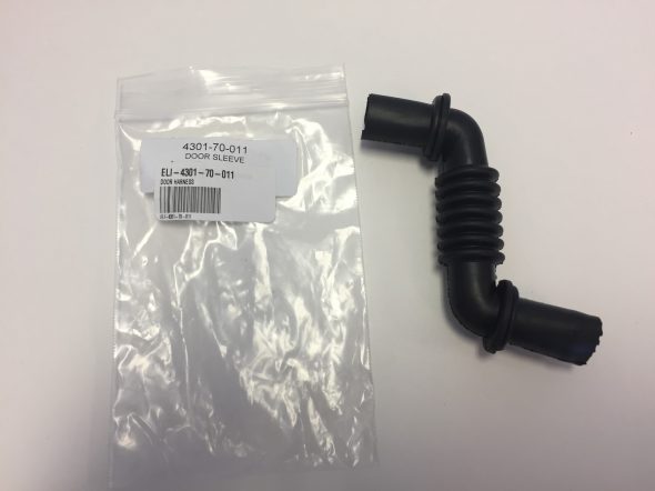
I never did find anything that was totally satisfying; however, I did locate some soft rubber looms that seems to offer the best option for me. They are very flexible and will compress and extend nicely. These came from Summit Racing but are produced by Electric-Life Power Windows and Accessories: https://www.electric-life.com/product/4301-70-011-58-diameter-flexible-inclined-rubber-tuber/  part number – 4301-70-011 5/8″ diameter Flexible Inclined Rubber Tube. To install it was necessary to drill a 3/4 hole in the pillar and the door at each location.

Rubber Door Loom

Rear Door Rubber Loom Installation

Front Door Rubber Loom Installation

Wiring

The electrical control circuit for the power locking system is comprised of two components. The first is the MES central locking system that will function properly without the addition of the wireless entry unit. In fact, the directions specify full installation and system testing of the MES central locking system alone. Only after the MES central locking system is functioning as it should, does one then add the keyless entry unit.

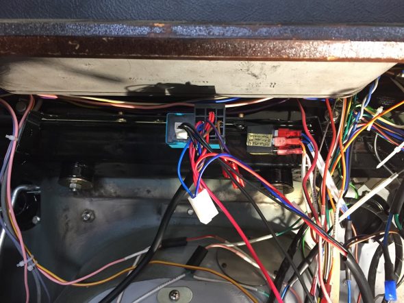
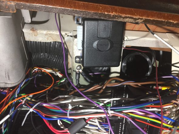
The MES control module is the turquoise blue box in the photo at the top of this post. A five way relay and a spade connector for ground wires is incorporated into the control module. I decided to mount the control module below the newspaper shelf and behind the radio. I installed several nutserts into the brace below the newspaper shelf to mount relays. The MES control module is secured with one #10-24 x 1/2″ machine screw and shake proof washer.

MES Control Module Mounting

I chose to locate the AVITAL 2101/712T keyless entry module on the chassis brace behind and below the cubby box. This location is also directly above where I chose to locate the Classic Technologies Fuse Box. The AVITAL unit has four mounting tabs; however, it weighs next to nothing so I used only two of the mounts with two #10-24 x 1/2″ machine screws and shake proof washers. 

I apologize for the wiring mess in the photo. I will clean all this up upon final installation.

Nutserts installed to mount keyless entry module

AVITAL keyless entry module mounted

The actual wiring circuit for the central locking/keyless entry system may be found at the “New Wiring Harness Circuits” web site entry: https://valvechatter.com/?p=8114

The wiring for this project is fairly easy to install, however, because of the connections that must be made between the MES central locking system and the AVITAL keyless entry component, the schematic for the wiring does appear to be fairly complicated.

After installing the four door actuators and rod linkages, the two control modules, and all the wiring I energized the system and everything worked beautifully. I anticipate that this is one feature that I will enjoy. Having to lock and unlock the rear doors by reaching into the car and adjusting the handle could be a bit of a nuisance. Modern cars have spoiled us (me).

Center Console Arm Rest

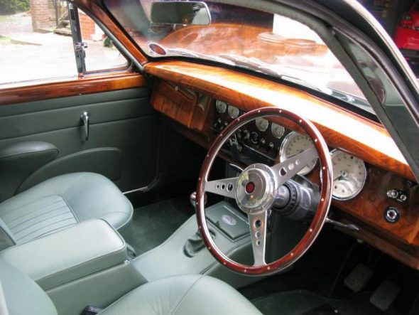
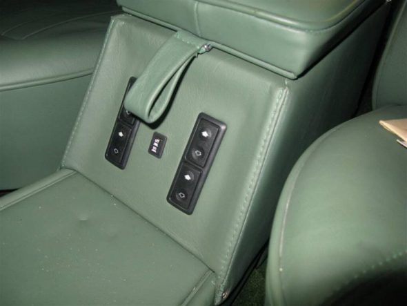
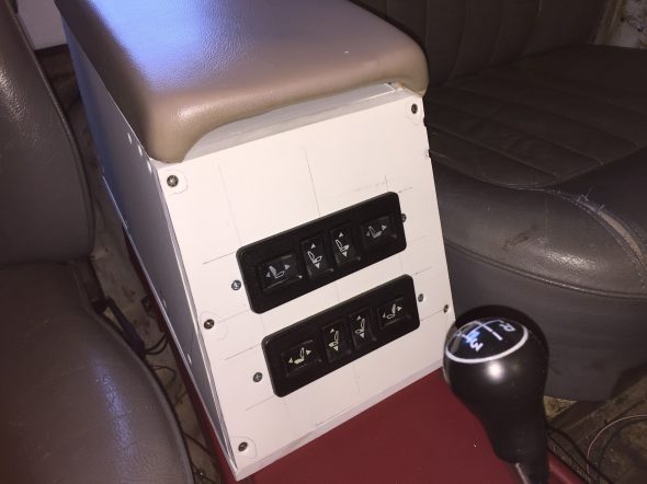
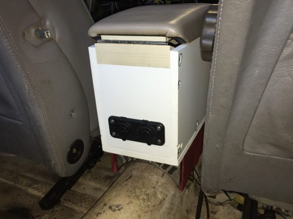
Inspired by Kevin Moore’s MK2 center console arm rest modification, I endeavored to create my own. I knew that I wanted to use an arm rest pad that would not look home-made, and that would also house the controls for the power seats and a USB dual port. These are images of Kevin’s console/arm rest:

Kevin Moore’s Console/Arm Rest

Kevin Moore’s Console/Arm Rest

I think that Kevin’s execution is spot on and well done. I can only hope that mine turns out as well!

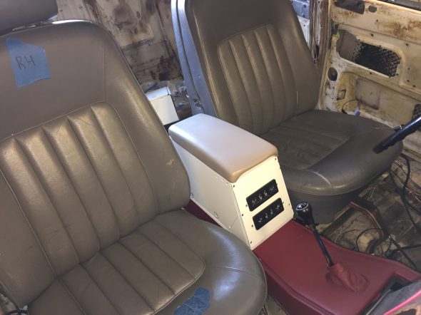
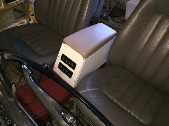
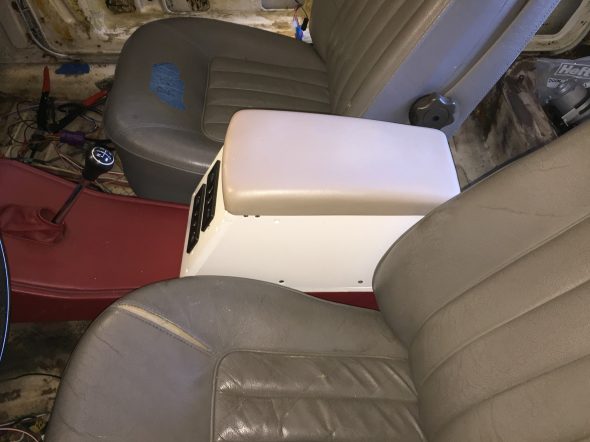
My project began with an arm rest pad/lid and storage tray that I purchased on eBay. I believe they were from a mid-eighties XJ6. The size and shape of the arm rest determined the ultimate measurements of the box I would build. The XJ40 electrically controlled power seats in my car mount slightly rearward of the original MK2 seats so I determined that I would add a couple of inches of sheet metal to the rear end of the original MK2 console/heater pipe cover. I should also mention that I am not using the heater pipes to the rear in my car. Moving the “box” rearward also gives more room for shifting the gearbox.

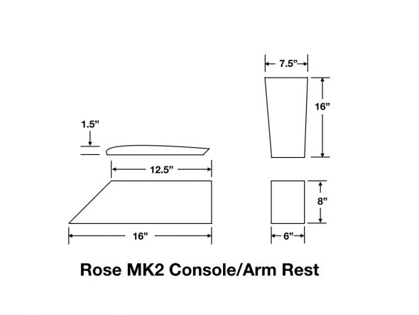
These are the outside dimensions of the “box” I constructed:

Rose MK2 Console-Arm Rest Dimensions

I constructed the “box” from a 1/2″ PVC panel. I chose the material primarily because it doesn’t absorb any moisture, but I also found that it is very easy to work with – much easier than plywood or some other composite material. A few 1-1/2″ poplar wood braces were also used for extra support. The panels of the box were all cut on a portable construction table saw, the holes for the seat switches were cut with a hand held saber saw, and the holes for the USB ports were cut using a hole saw.

My next step will be to cut matching panels from 1/8″ PVC. These will then be glued to the 1/2″ panels. This will completely cover all of the screw heads and mounting indentations and should produce a nice finished surface for the leather.  Ultimately, I will mount the “box” to the original heater pipe cover and to the prop shaft tunnel as Kevin did.

These are a few images with the “box” just sitting (not mounted) in position:

Console Arm Rest RH Front View

Console Arm Rest LH Front View

Console Arm Rest LH View

The following two images show the mounting of the electrical switches in the front and the twin USB ports in the rear. The screws in the face plate of the USB mounting bracket will be replaced with black screws. As I mentioned previously, additional sheet metal will be added to the end of the heater pipe cover so that it matches flush with the rear edge of the “box.”

Console Arm Rest Seat Controls

Console Arm Rest USB Ports

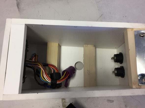
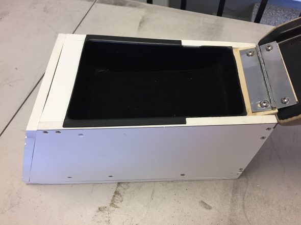
The last two images show the interior of the box with and without the storage tray:

Console Arm Rest Box Interior

Console Arm Rest Storage Tray

Of course, the beige arm pad, the grey seats and the red original heater pipe cover will all get reupholstered in a single color leather!


Power Steering Pump Cover

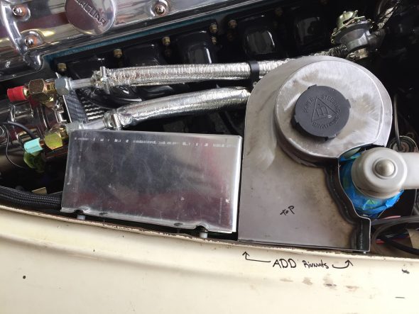
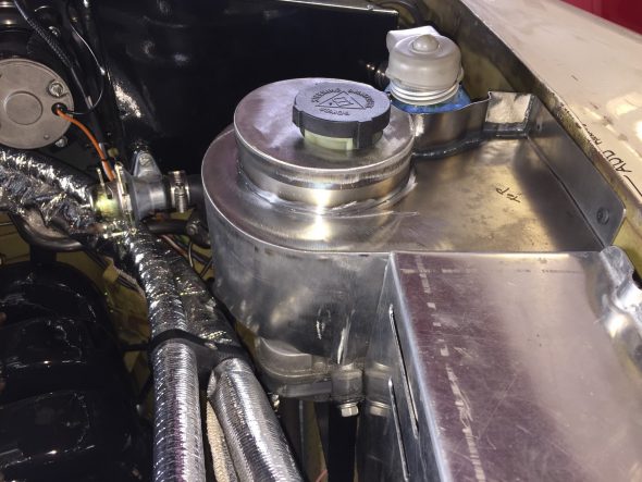
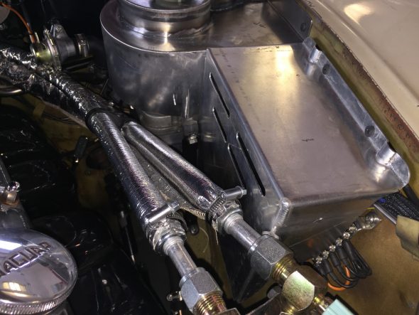
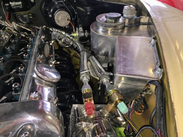
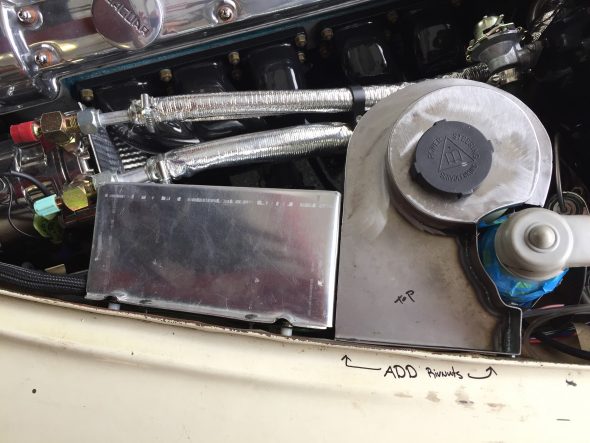
Although my MK2 could have had power assisted steering from the factory, it did not. I elected to add an electric power steering pump and rack and pinion steering to my car. The kit was purchased from M&C Wilkinson in the UK. http://www.mandcwilkinson.com The kit uses a combined power steering pump and reservoir that is mounted in a supplied bracket. It is frankly a bit unsightly sitting next to the polished cam covers and porcelain exhaust manifolds of the 3.8 Jag power plant! However, I was resigned to leaving it as it was until Mike Gassman, owner of Gassman Automotive http://www.gassmanautomotive.com, convinced me that a cover should be made.

Make and his welder/fabricator Brandon Tyree designed and fabricated the cover seen below. It mounts to the LH engine bay valance with only two 10-24 x 1/2″ machine screws. One simply unscrews the two screws and removes the reservoir cap then lift away the cover. It will be painted gloss black to match the heater box.

I have to say that as usual Mike was correct and Brandon’s cover came out quite nice in my view! 

Electrical Connections Box and Power Steering Pump-Reservoir Cover

Power Steering Pump/Reservoir Cover

This is a short video showing the removal and installation of the cover:


Seating

Front Seating

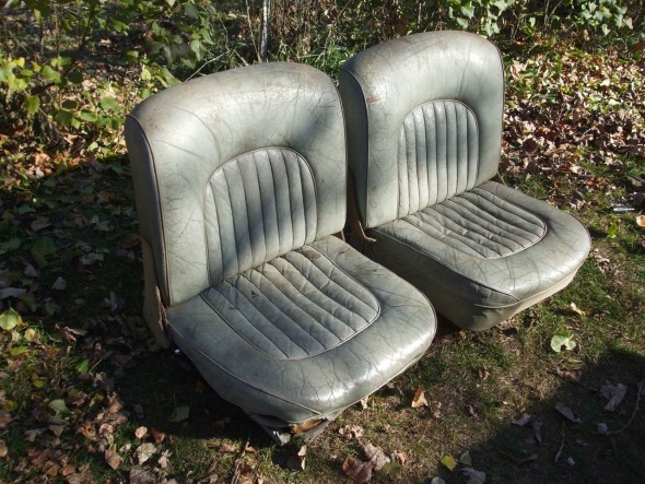
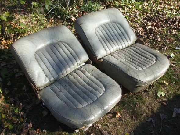
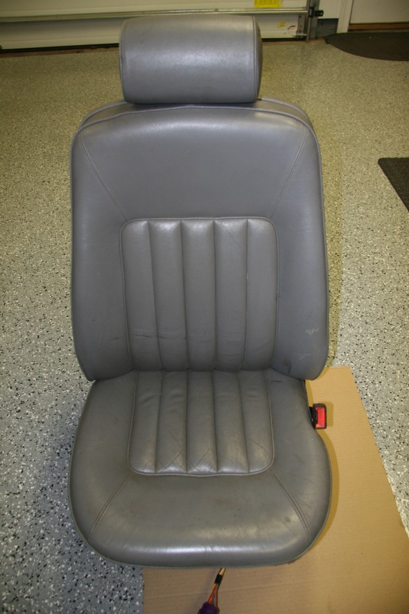
Following considerable thought I have decided to install front seats from a later model Jaguar in my MK2. At first I pursued the original tilting seats that were available from Jaguar as an option at the time. I actually found and purchased a pair. they were in rough shape, but the frames were just fine and that was all I was really after.

Jag MK2 Optional Tilting Seats

Jag MK2 Optional Tilting Seats

Jag MK2 Optional Tilting Seats

Jag MK2 Optional Tilting Seats

However, after seeing the installation of Daimler seats in Ton Tulleken’s restored Jaguar MK2, I decided that I must have the same seats for my restoration! Ton’s site is in Dutch but the photos work in all languages.

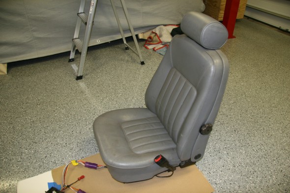
I could not locate any Daimler seats in the U.S. so I turned to Ton who is from the Netherlands and he was able to help me. Hendrikus Alkema who runs and owns New and Used Parts Jaguar Daimler in the Netherlands had a full set of 1990 Daimler seats available. I ordered the two front seats as well as all four headrests from the car. The seats came complete with the wiring harnesses and switches.

The seats arrived two days after the order was placed! DHL had them on my doorstep. On one of the seats the lumbar support knob was broken in transit, but Hendrikus sent a replacement to me right away.

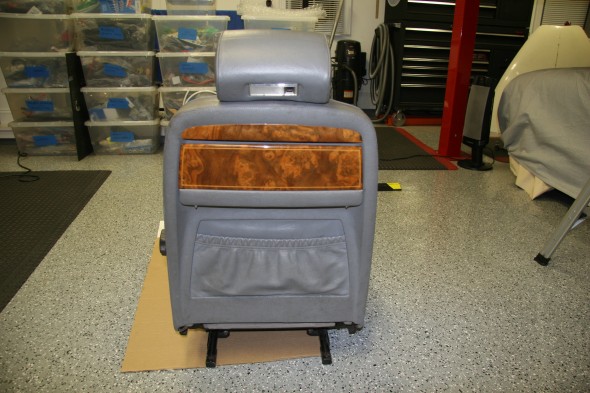
1990 Daimler Front Seats

1990 Daimler Front Seats

1990 Daimler Front Seats

1990 Daimler Front Seats

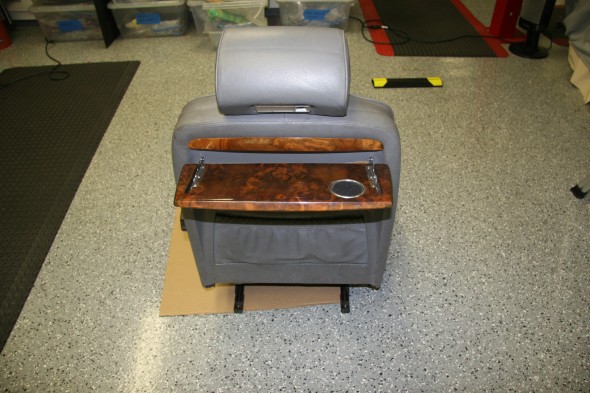
The picnic tables on these seats are particularly nice and much more functional than the ones on the MK2 seats.

1990 Daimler Front Seat Picnic Table

1990 Daimler Front Seat Picnic Table

1990 Daimler Front Seat Picnic Table Open

1990 Daimler Front Seat Picnic Table Open

The seats I purchased are slightly different than Ton’s as my headrests are not adjustable. I will have the seats recovered over new seat foams when the time comes.

Of course, the primary advantage of these seats is their adjustability. Each seat has four motors. Two for the lower and two for the upper cushion. The seats also have seat heaters (non-functional apparently) and the driver’s seat has a memory function.

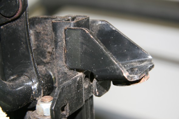
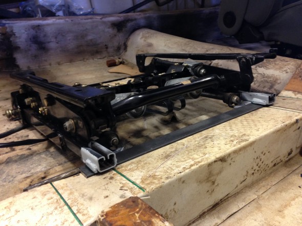
Most folks cut down the height of the floor brace in the interior to install the modern seats; however, Ton did not do that and I am going to at least try it this way before cutting them back. I like the idea of being able to go back to the original seats if I, or another owner, decided to do so in the future. As Ton did, I made a brace for the seat frames from angle iron and had them welded to the frames. I will then drill them for mounting through the original holes of the seat supports into the floor brace.

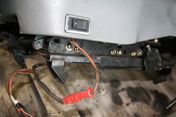
Front Foot on XJ40 seat frame

Front Foot on XJ40 seat frame

XJ40 seat frame front foot

XJ40 seat frame front foot

XJ40 seat frame front foot removed

XJ40 seat frame front foot removed

The front foot shown in the image above must first be removed.

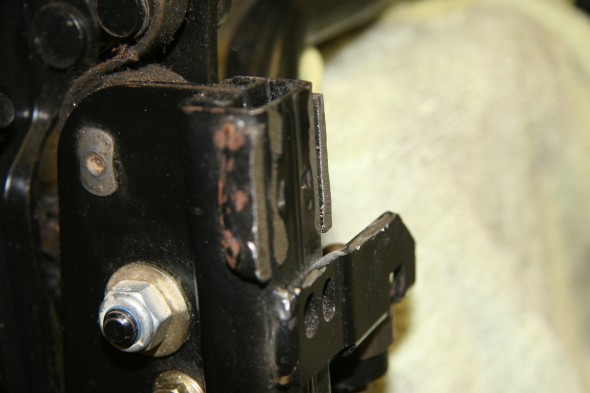
New front mounting bracket in place with front foot removed

New front mounting bracket in place with front foot removed

The image above shows the new bracket in place prior to welding to the seat frame.

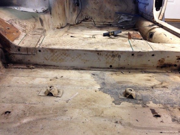
Floor Brace and seat mounting captured nuts

Floor Brace and seat mounting captured nuts

The image above shows the four holes with captive nuts in the floor brace that are used to mount the new seat frame to the floor.

The wiring had its own set of challenges. Details about the wing may be found in the “Building a Wiring Harness” post.

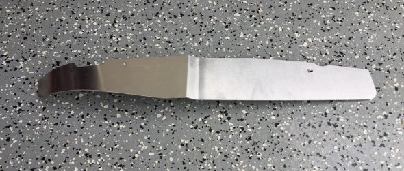
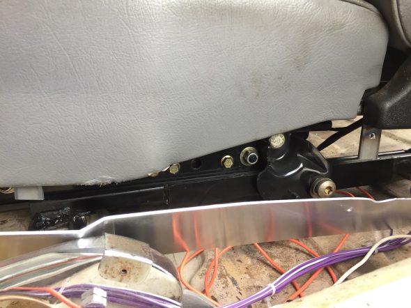
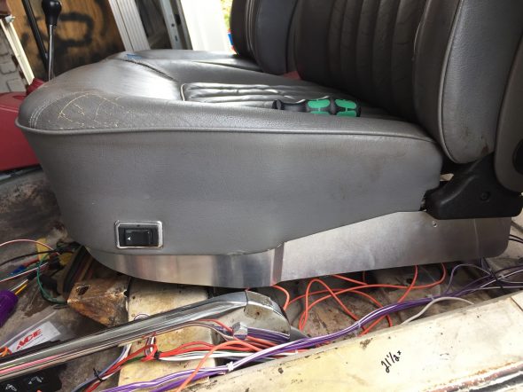
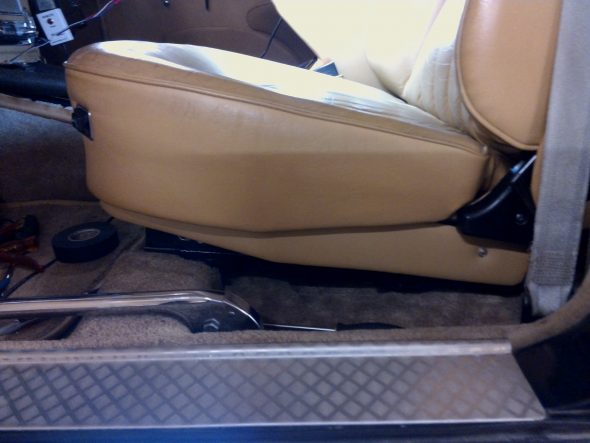
Ton suggested making “skirts” for the lower portion of the seats so that the seat mounting frames would not be visible when the door is opened. I followed suit. Brandon Tyree, metal welder/fabricator at Gassman Automotive, made the skirts from sheet metal for me. These will be covered with leather/vinyl when the interior upholstery is finished.

Brandon welded metal tabs to the seat frames so that the sheet metal skirts can be screwed to the tabs to mount them to the seats. These are designed so that the skirts will move with the seats when the power functions of the seats are used.

LH Side Front Seat Skirt

Locating Tabs for LH Side Front Seat Skirt

LH Side Front Seat Skirt Installed


This is an image of his finished product:

Ton Tulken’s Front Seat Skirts

Original Seat Mounting

Seat Supports

Details on the removal of the seat runner assemblies or seat supports may be found in the disassembly note, entry 45 https://valvechatter.com/?p=1803, and entry 6 https://valvechatter.com/?p=297.

Each support is mounted to the floor brace with four 1/4″ – 28 x 5/8″ pointed tip, slotted machine screws with flat and shakeproof washers. The rear mount for the seat to the seat support is a 1/4″ – 28 x 1″ hex head bolt with shakeproof washers. An insulation pad was found cut to fit under each seat support.

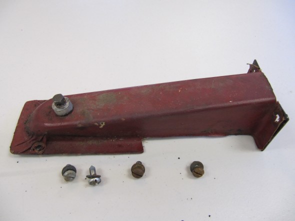
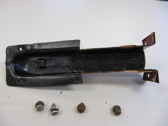
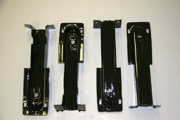
I removed the vinyl from each of the four supports, media blasted them  and painted with POR-15 to be covered with new vinyl later.

Seat Supports

Seat Supports

Seat Supports

Seat Supports

Seat Supports

Seat Supports

Seat Supports

Seat Supports

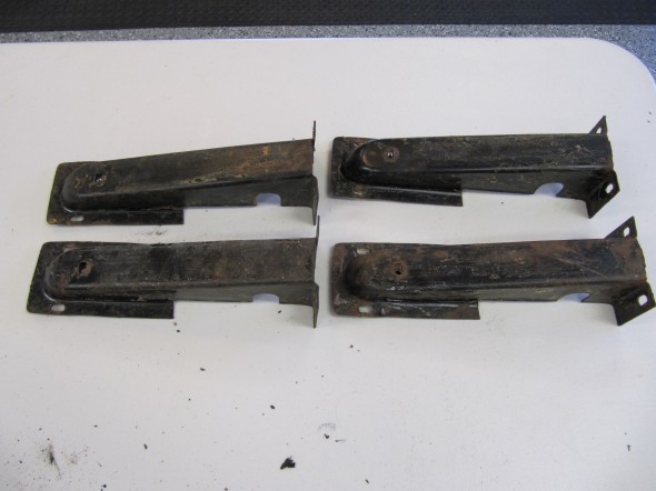
I media blasted the four seat supports and prepared them for painting:

Front Seat Support

Front Seat Support

Front Seat Support

Front Seat Support

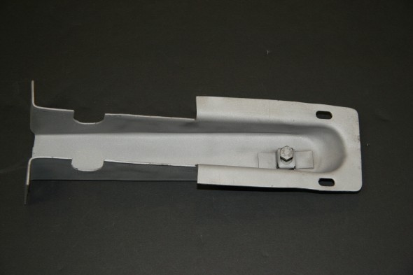
Seat Supports Painted

Seat Supports Painted


Original Fuse Box Modification

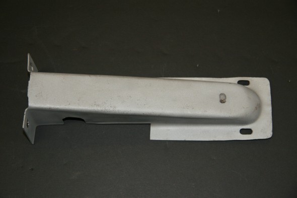
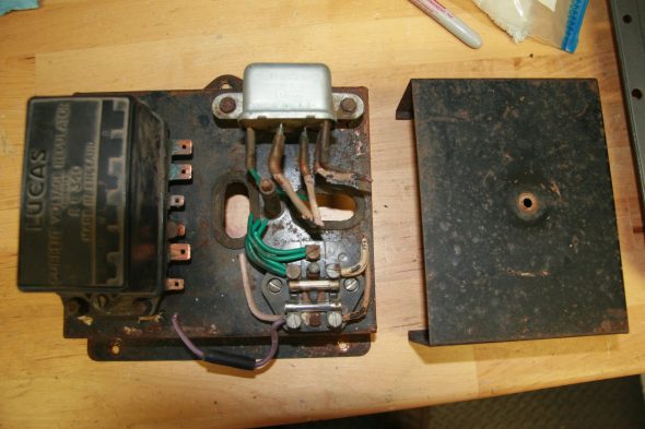
The original electrical system on them MK2 was protected by two fuses. The fuse block was located on the control box bracket assembly mounted on the LH engine bay valance. The voltage regulator and the horn relay were also located inside the control box. The bracket assembly had a metal cover secured by a thumb screw that protected the electrical connections to the relay and fuse block.

Original Control Block, Bracket Assembly and Cover

As explained in other electrical system entries to this website, I am using the Classic Technologies fuse/relay panel that provides for 15 fused circuits with 34 pin connectors, 7 relays including horn, ignition power, fog lights, high beams and low beams headlights, starter and accessory power and 2 flashers for the turn signals and hazard lights. The Classic technologies Fuse Box is located under the dash fascia on the RH side of the interior.

Classic Technologies Fuse and Relay Box

In my revised wiring system I used the bracket assembly as a cover for three barrier blocks used for wiring runs to the front of the car. I know the terminals and wiring appear a hodgepodge but it was necessary to configure them in this fashion to hide them all under the bracket assembly!

Barrier Block Terminals Under Original Fuse Panel Assembly

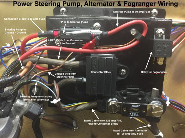
The top of the bracket assembly was then used to mount a number of other electrical connections:

Power Steering Pump Alternator Fogranger Wiring on Bracket Assembly

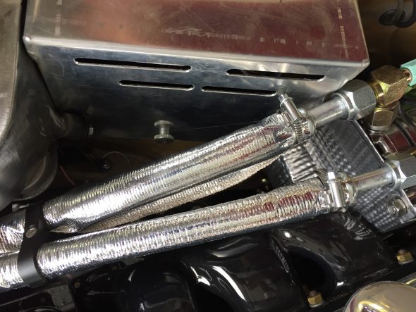
The original control box cover would no longer cover, nor fit, the bracket assembly. I turned to Brandon Tyree, welder/fabricator at Gassman Automotive http://www.gassmanautomotive.com to fabricate a new electrical connections box cover. The images below show the cover. In final form it will be painted gloss black to match the heater box. The box is mounted to the valance with two 10-24 x 1/2″ machine screws and the original thumb screw slightly repurposed. Four slots were designed into the face of the box to permit heat to escape. The box sits very close to the exhaust manifolds and I did not want it to collect the heat.

Electrical Connections Box and Power Steering Pump-Reservoir Cover

Electrical Connections Box and Power Steering Pump Cover

Electrical Connections Box and Power Steering Pump-Reservoir Cover

Electrical Connections Box Cooling Vents


Fuel System

Petrol Filter

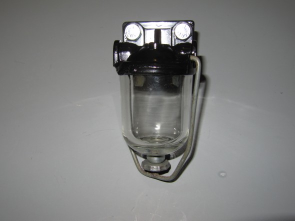
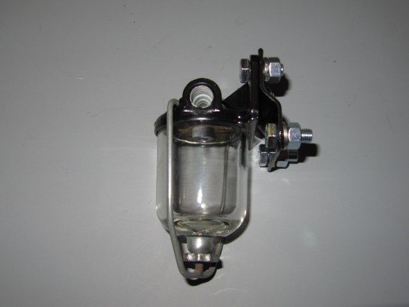
AC supplied the fuel filtration device for the Jaguar. My early version includes a filtration screen, but newer versions have a paper filter in the bowl.

The filter is bolted to a mounting bracket with two 5/16″ – 24 x 3/4″ hex head bolts, split washers and hex nuts. The bracket and filter are then mounted to the RH wing valance with two 5/16″ – 24 x 3/4″ hex head bolts, split washers and hex nuts.
Petrol Filter
Petrol Filter

Petrol Filter & Bracket

Petrol Filter & Bracket

I trial fit the fuel filter and fuel pipe to the RH valance.
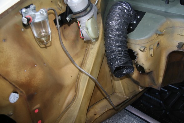
Fuel Filter and Fuel Pipe Installed

Fuel Filter and Fuel Pipe Installed

Fuel Lines

I am replacing the hard brake lines, but the original hard fuel lines were in very good shape. I just cleaned them before reinstalling.
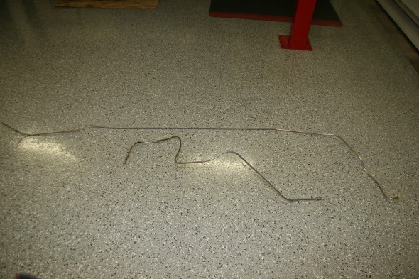
Cleaned Fuel lines


The hard fuel lines run along the RH frame rail. Rather than using the original mounting clips, I used a double stainless steel clip that permitted running the fuel and brake pipe in parallel on one side of the clip and the battery cable in the other. Information and photos of the fuel line installation can be found here” https://valvechatter.com/?p=6627.

Petrol Tank Filter

I ordered a new filter for the tank.
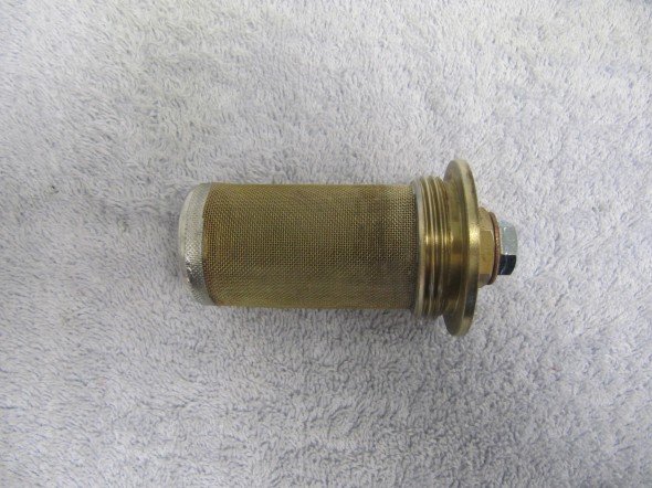
Petrol Tank Filter

Petrol Tank Filter

Petrol Pump

I ordered a new SU electronic petrol pump to replace the old, but still functioning unit.
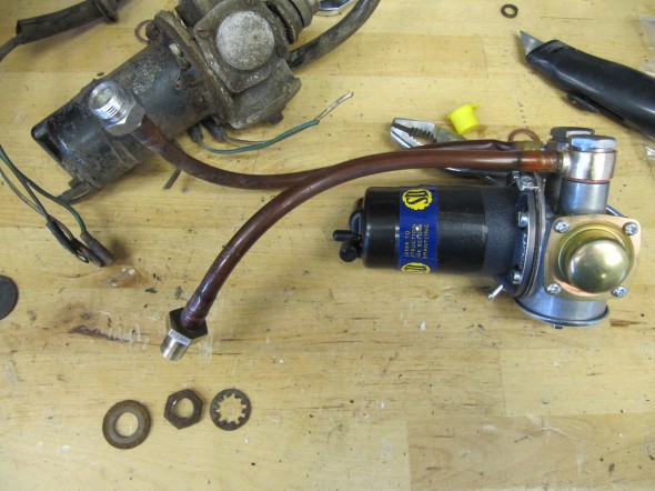
SU Electronic Petrol Pump AZX1308EN

SU Electronic Petrol Pump AZX1308EN

As part of the trial fitting process, I installed the two rubber grommets with their metal “distance tubes” in the boot. Pushing the grommets into place is no easy task. I placed them in boiling water for a few minutes to soften them and it did seem to help. Also put a little vaseline on the mounting plate to which they are affixed.
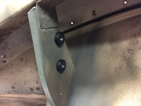
Petrol Filter & Bracket

Petrol Filter & Bracket

A black 14 AWG wire is used as the ground for the pump and it attaches to the mounting plate via a #10 – 32 x 1/2″  machine screw, flat washer, split washer, and nut. A spade connector is located on the pump for the other end of the wire.
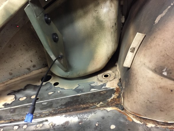
Ground Wire Mounting for Fuel Pump

Ground Wire Mounting for Fuel Pump

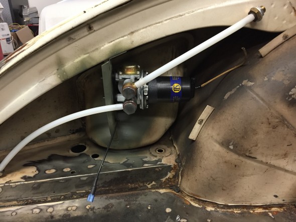
I cut the new nylon hoses, sourced from SNG Barratt, to length using the originals as patterns, and pressed them onto their pump fittings. I then installed the pump by inserting the pump mounting studs through special large washers (to evenly compress the rubber grommets) and then fastened in place with lock washers and nuts.
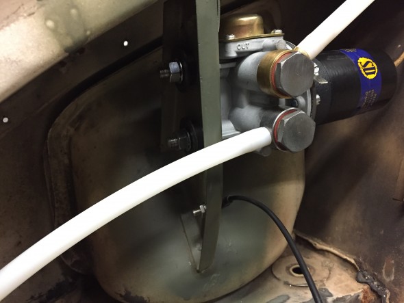
Fuel Pump Mounting Studs, Special Washers and nuts
Fuel Pump Mounting Studs, Special Washers and nuts

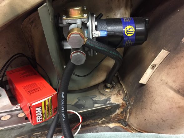
Installed Fuel Pump with Nylon Hoses

Installed Fuel Pump with Nylon Hoses

Petrol Hoses

New petrol hoses were purchased for installation. I had purchased the hard nylon tubing from SNG Barrett as shown in the image above, but have since decided to use rubber fuel hose. The rubber hose is easier to work with. I did not want to use the fuel tank for the fuel source for  a test start-up of the engine, so I plumbed the fuel pump, including the relocated fuel filter, and will use a five gallon plastic fuel can sitting in the spare tire well.
Fuel Pump Hose Fittings 5/16″ Rubber Fuel Hose
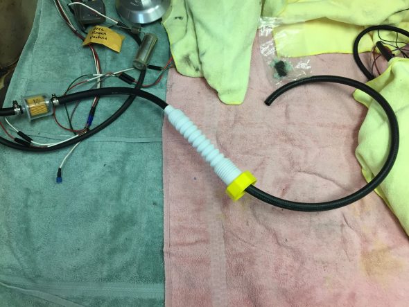
Fuel Hose with Filter to Temporary Fuel Source


The petrol hose fittings from the petrol pump were cleaned and clear cad plated for re-use.
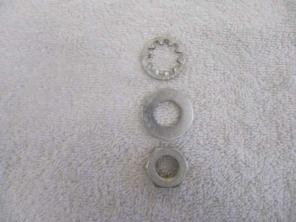
Fasteners for Petrol Pump Hose

Fasteners for Petrol Pump Hose

The image below shows these fasteners securing the fuel hard line that travels to the front of the car from the fuel pump. The image was taken from the floor, looking up to the underside of the boot.
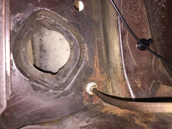
Fuel Connection From Pump to Pipe to Engine Bay

Petrol Tank Element Unit

The unit is secured to the tank with six set screws and 12 copper washers and a cork seal. The unit is positioned in the tank so that the float is toward the front of the car. I did check the fuel gauge with my multimeter and found it to be functioning properly. The swing motion of the Petrol tank Element Unit float arm worked just fine and the interior of the units seemed to be clean and without damage so I just cleaned up the exterior of the mechanism and got it ready to reinstall when the time comes. I ordered a new seal.
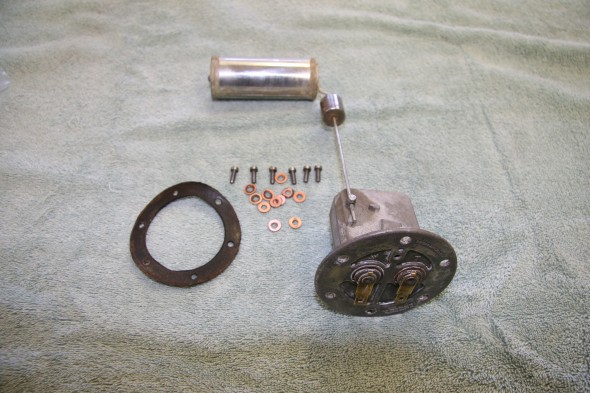
Petrol Tank Element Unit, Seal and Fasteners

Petrol Tank Element Unit, Seal and Fasteners

Throttle Link Rod Assembly on Trunnion

I just media blasted this throttle controls component to zinc plate for reuse.
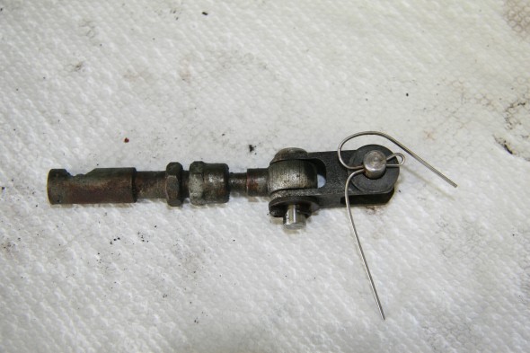
Throttle Link Rod Assembly on Trunnion
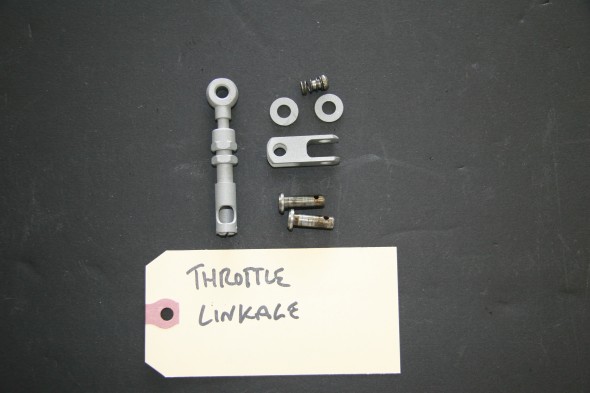
Throttle Link Rod Assembly on Trunnion

Throttle Link Rod Assembly on Trunnion

Throttle Link Rod Assembly on Trunnion

SU HD6 Carburetors

I am using the original HD6s used on my 3.8 motor. The carbs and all of the hardware were cleaned and inspected by Joe Curto and rebuilt by Mike Gassman. Mike tuned for the run-in, but I will re-tune after the engine is in the car and operating with load. These are tuning instructions located on the Moss Motors website:

SU Carb Tuning

Carburetors Fuel Feed Pipe

I am not using the original “pancake” air cleaner designed for the 3.8 MK2. I just cannot cover up the beautiful twin cam engine with a big ugly air cleaner, so I will be using small air cleaners located at each carb. This does create a few logistics problems. For starters, the original carb fuel feed pipe junction fitting and flexible line to the fuel filter on the RH engine bay valance conflict with the front air cleaner. This image illustrates the problem with fitting individual air cleaner using the original fuel feed pipe.
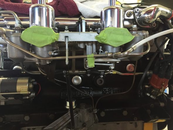
Original Fuel Feed Pipe to Carbs

Original Fuel Feed Pipe to Carbs

I had a new fuel feed pipe made using the original fittings with a relocated junction to avoid the problem.
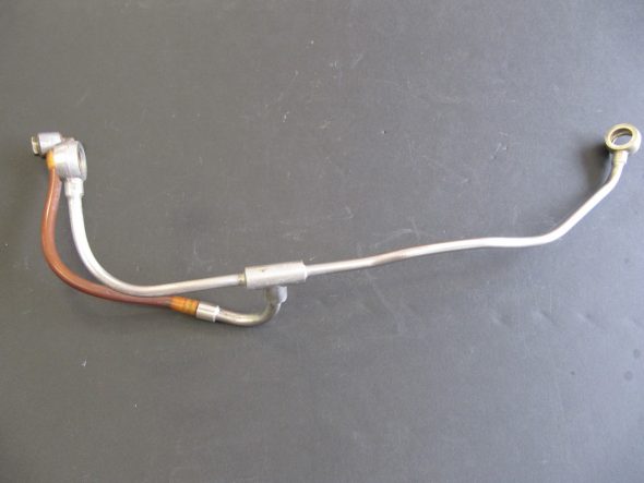
Original Carb Fuel Feed Pipe & Fittings
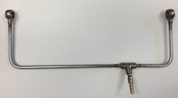
Original Carb Fuel Feed Pipe & Fittings

Modified Carb Fuel Feed Pipe

Modified Carb Fuel Feed Pipe


The Auxiliary Starting Carburetor – Otter Switch

The auxiliary carburetor is an enrichment device to make starting the car easier. The unit is actuated by a thermostatic switch (Otter Switch). These switches are notorious for failure; however, Mike Eck, best known for his Jaguar clock repair, upgrades the original Otter Switch by by putting a sealed thermostatic module inside it, so it looks the same as it did originally but works reliably.  At the time I had his improvement fitted he charged $45 for the modification.
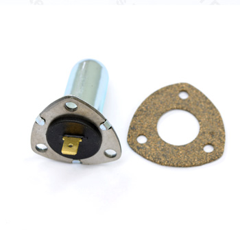
Otter Switch

Otter Switch

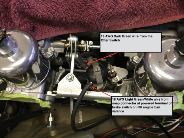
The electrical connection from the otter switch to the solenoid of the enrichment carb is achieved with a dark green 18 AWG wire in a rubber sleeve. 
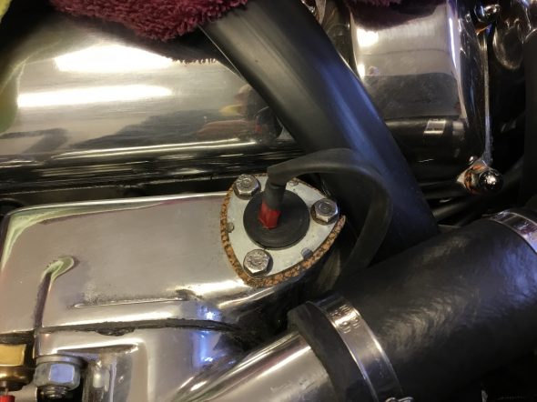
Otter Switch Electrical Connection to Auxiliary Starting Carb

The thermostatically controlled enrichment caburetter is actuated by a solenoid. The additional electrical connection for the solenoid comes from a four way snap connector on the RH engine bay valance. The connector joins the 18 AWG light green/white from the enrichment carb solenoid with the wire emanating from fuse position #22 to the brake switch. In other words, the starting carb gets its power from the powered side of the brake switch located on the RH engine bay valance.
 

Trial Installation Update

Carburetor Mounting

I installed the carbs as an assembly. I loosened the couplings between the connecting rod and the throttle spindles, fully closed each butterfly and then secured the couplings. In my case because I am not using the original air cleaner, I had to remove the dowel bolts that connects the throttle stop bracket between the front and rear carbs. I replaced the dowel bolts with 5/16″-24 x 1″ hex head bolts and nuts. After the carbs were mounted to the inlet manifold I removed the two nuts and the 1″ hex head bolt was then used for the installation of the air cleaner.

Before mounting the carb assembly on the inlet manifold I first installed one gasket (c.7221), then an insulator block (C.8486) and then another gasket (C.7221) on the four 5/16″-24 inlet manifold studs for each carburetor.
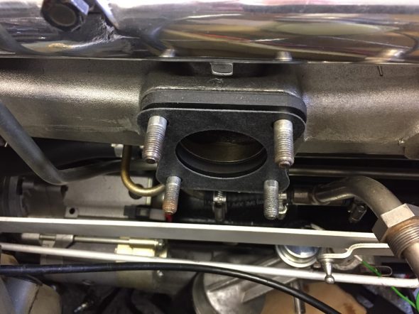
Gaskets and Insulator Blocks between Carb Bodies and Inlet Manifold

I then mounted the assembly and securely tightened split washers and nuts on each of the eight studs. Before tightening the two nuts/washers on the lower studs of the front carburetor, I reinstalled the bracket assembly for the throttle return spring anchorage. I cleaned and painted the bracket but this is what it looked like prior to “clean-up.”
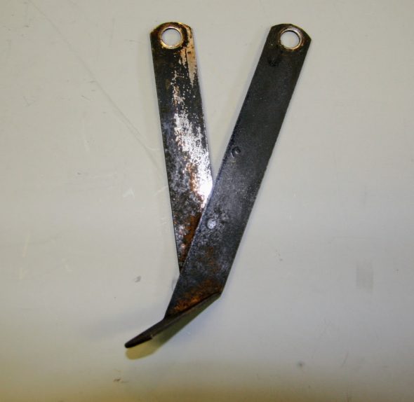
Bracket Assembly on Front Carburetor

Fuel Delivery

After the carburetor assembly is mounted on the inlet manifold, the starting pipe assembly is connected with two short pieces of neoprene fuel hose requiring four Jubilee Hose Clips. I don’t have a good photo of the staring pipe full assembly, but these are the three components that screw into the underside of the inlet manifold.
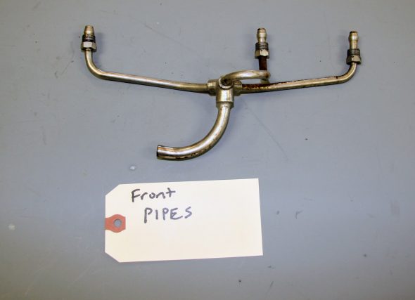
Front Manifold Starting Pipe Assembly
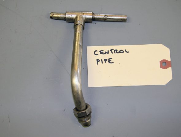
Center Manifold Starting Pipe Assembly
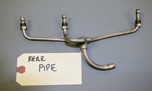
Rear Manifold Starting Pipe Assembly

The neoprene hose connections are not simply made and must be done from below the car. These can be seen in the photo below, although they are somewhat difficult to ascertain. The photo was taken from below the car.
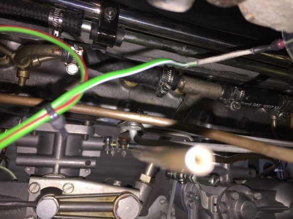
Manifold Starting Pipe Assembly Fuel Hose Connections

I have decided to move the fuel filter from the engine bay. 

I am sure that the original design is perfectly fine, but I was never fond of Jaguar’s placement of the fuel filter on the RH engine bay valance. The filter has a glass bowl that is functional permitting easy viewing of fuel flow and any sediment caught by the filter, but I am leary of fuel in glass in an engine compartment. With no insulation, the fuel is also subject to “boiling” after the engine has been run and then parked due to residual engine heat. 

Eliminating the original AC fuel filter from the engine bay also gives me some much needed room under the bonnet. With my modifications including air conditioning, power steering, and carb mounted air cleaners among other items, space in the engine bay is at a premium.

Jaguar located the petrol pump in the LH side of the boot and I decided to do the same with the fuel filter. I will install a Fram G-2 opaque plastic filter  between the fuel tank and the fuel pump.
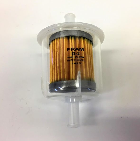
Fram G-2 Fuel Filter

I cut the long 5/16″ steel fuel line that travels along the RH frame rail from the rear of the car to the front slightly above, but near the oil filter. I installed a ninety degree elbow female compression brass fitting to the end of the fuel line. Holyoke P/N 70-54, 5/16 compression to 1/4 NPT. The elbow is attached to a male 1/4″ NPT to 5/16″ barb fitting.  I then ran a 5/16″ ethanol resistant rubber fuel hose from the barbed fitting to the barbed fitting on the carburetor fuel delivery pipe. Used two 11-16mm jubilee hose clamps.
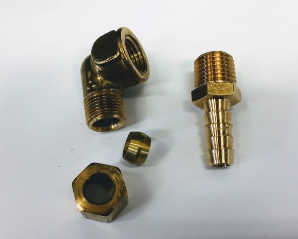
Brass Connection Hardware from Fuel Pipe to Rubber Fuel Hose
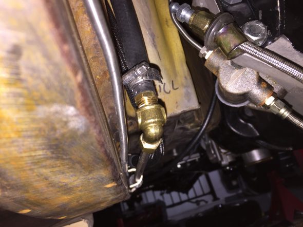
Fuel line from tank is connected to the rubber fuel hose that is routed to the Caburetters

A Jubilee Hose Clip is used to tighten the hose on the barbed fitting.

The image below shows the new rubber fuel hose running from the head fuel line under the car to the carburetor fuel feed pipe.
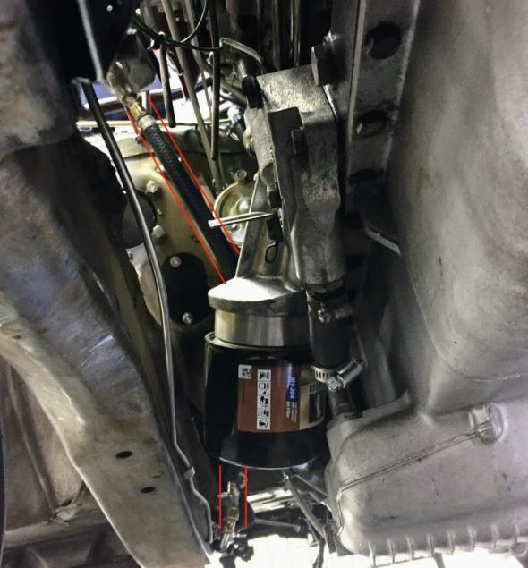
Fuel Hose from Carb Fuel Feed Pipe to Hard Pipe from Tank

Throttle Return Springs

With all of the fuel delivery hose connections made, I then attached the throttle link rod assembly on trunnion – part #81 in the schematic to the bell crank lever assembly from the accelerator controls and tightened the securing screw holding the ball joint together.
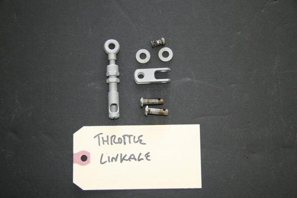
Throttle Link Rod Assembly

I then moved onto the throttle return springs. The shorter spring is the return spring from the lever on the front carburetor to the anchor bracket mounted below the front carburetor (photo shown above). The longer spring is the return spring from the linkage to the Bracket on the Oil Cleaner.
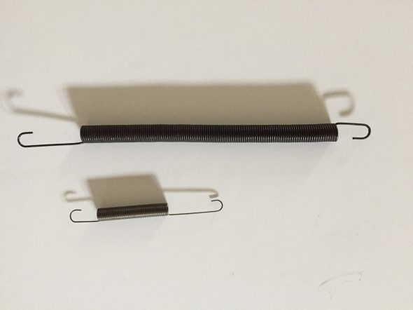
Throttle Return Springs

My next step was to loosen the two float chamber overflow pipes at the float bowls so that the pipes could be aligned and routed through the clip near the oil filter.

Air Cleaners

As previously mentioned, I am using carb mounted air cleaners rather than the original contraption that I am confident worked well but completely covered up the beautiful twin cam engine. After experimenting with a number of options, I settled on air cleaners sourced from Advanced Performance Technology (APT) http://www.aptfast.com. These air cleaners use K&N Filters.
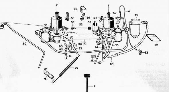
Carb and Fuel Connections Schematic

The “intermediate throttle lever from throttle link to stop bracket” – part# 82 in the diagram – on the  MK2 carb set up is offset to the rear of center. This requires a comparable offset in the air cleaner mounting to avoid the throttle lever striking the air cleaner casing as it travels its logical path.

I used filters that are 1-3/4″ tall. The rear cleaner is offset upward and is part number: SD24-318 for HD6 SUs. The front cleaner is center mounted and is part number SD4-318. The air cleaner casings are actually highly polished. The blue tint in the image below is a plastic protective coating that easily peels off.
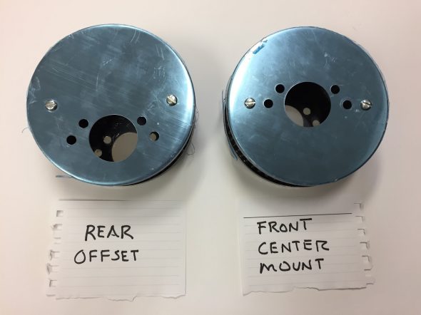
APT K&N Air Filters

A gasket is placed over the mounting studs for the air cleaners and then the back plate of the air cleaner is installed and secured. I used a 5/16″-24 x 3/4″  and a 5/16″-24 x 1″ for each air cleaner. The longer bolt is needed where it must also travel through the throttle stop bracket.
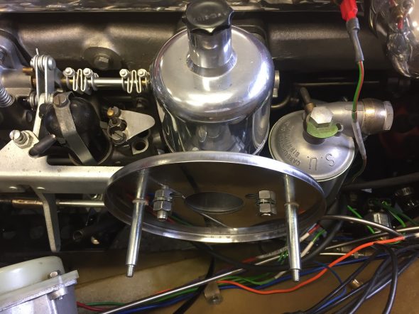
Air Filter Rear Plate Mounted

The K&N oiled filter is then installed followed by the cover plates secured by shake proof washers and acorn nuts on the studs.
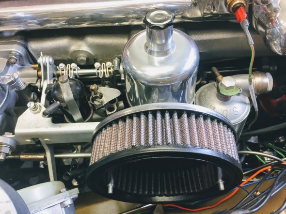
K&N Air Filter Element Installed
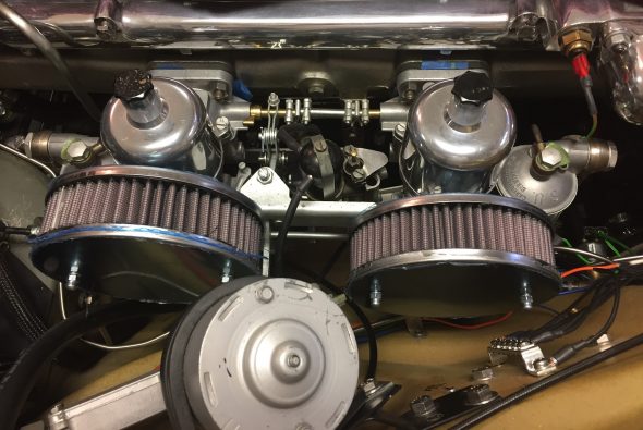
APT K&N Air Cleaners Temporarily Mounted

Air Cleaner Update – Cold Air Box

Well, after the time devoted to researching the ideal air cleaner solution and the expense of ordering the K&N offset filters, I became convinced that an air box delivering cool air to the carbs is the way to go. I recently saw several approaches to these “boxes” on some of the Jag Forums, and Mike Gassman of Gassman Automotive convinced me that the cold air delivery system would be a good modification to make to assist with expected heat problems under the bonnet. I anticipate that my air conditioning system will add more heat to an already “hot” situation. Mike has a very talented welder/fabricator on his team, Brandon Tyree, who designed, fabricated and installed the “box” – I am going to call it a “pipe.” I don’t know why “they” call these  things “cold air” boxes – they do not deliver cold air, but instead, ambient air from outside the engine bay to the carbs. A “pipe” also has all smooth and rounded surfaces which would seem to promote better air flow than a “box.”

This topic deserves a separate post and it may be found at: https://valvechatter.com/?p=9163
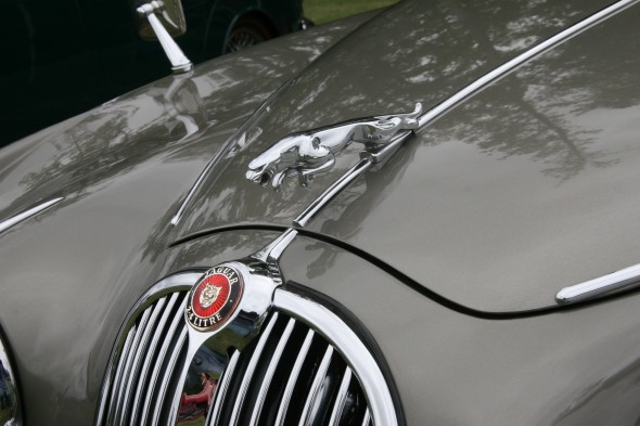
Coombs Rear Fender Skirts

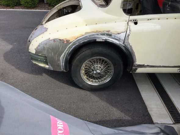
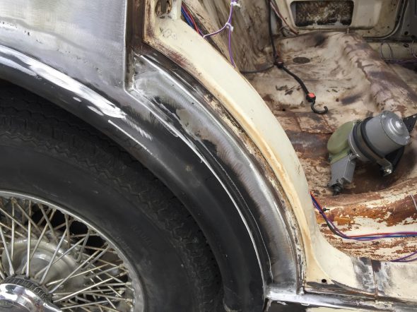
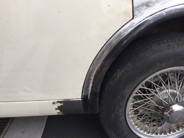
I purchased the Coombs rear fender skirts, or spats, some time ago from XKs Unlimited. The skirts are mounted to the body with a rear bracket, a clip in the middle, and Duz-type fasteners at the front. They do not fit particularly well and can shift about. John Stefanik, who did some masterful metal work on the car previously, had done some preliminary fitting of the skirts when he had the car in Pennsylvania.

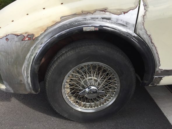
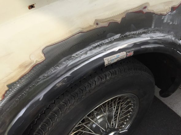
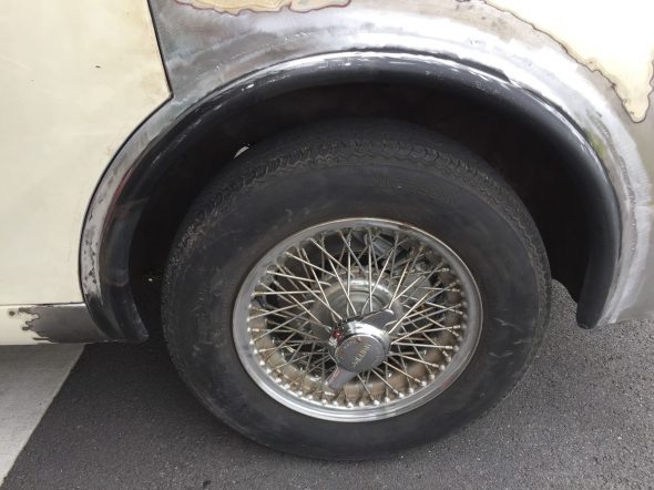
However, after seeing a number of fellows on the various Jaguar MK2 Forums weld these to the body rather than mounting as per usual, I was inspired to do the same. In my opinion once all of the bodywork is complete this will yield a much smoother and pleasing appearance. The rubber gasket that is typically used and visible is eliminated.

The original Coombs MK2s did not, in fact, use a skirt or spat, but accomplished the same effect by welding in a rod around the wheel opening to create a fender bead or roll similar to the front of the car. This, of course, also provided much easier access to the rear wheels/tires when racing. Reference is made to the rear wheel opening modification in the Coombs brochure of the time:Coombs Specifications for Jaguar MK2 (2)
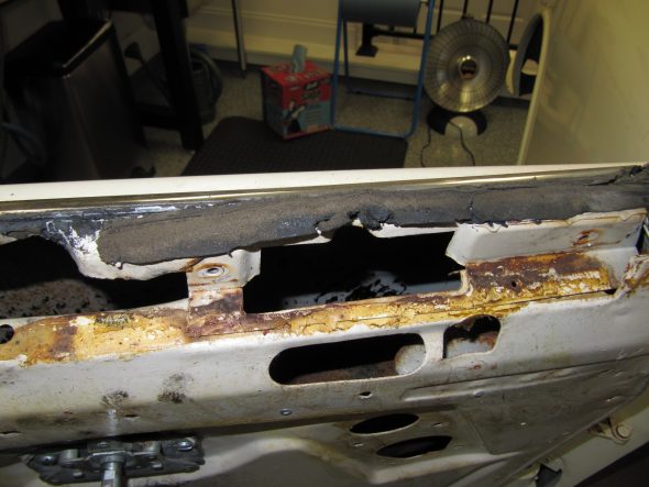
These skirts are available in steel as well as fiberglass. I had purchased the steel variant.

Brandon Tyree, welder and fabricator extraordinaire, at Mike Gassman’s Gassman Automotive shop http://www.gassmanautomotive.com did the welding work for me. All of the finishing touches will be handled when the car is returned for bodywork and paint.
Here are a few images of Brandon’s work:

Coombs Rear Wheel Skirts Welded

Coombs Rear Wheel Skirts Welded

Coombs Rear Wheel Skirts Welded

Coombs Rear Wheel Skirts Welded

Coombs Rear Wheel Skirts Welded

Coombs Rear Wheel Skirts Welded