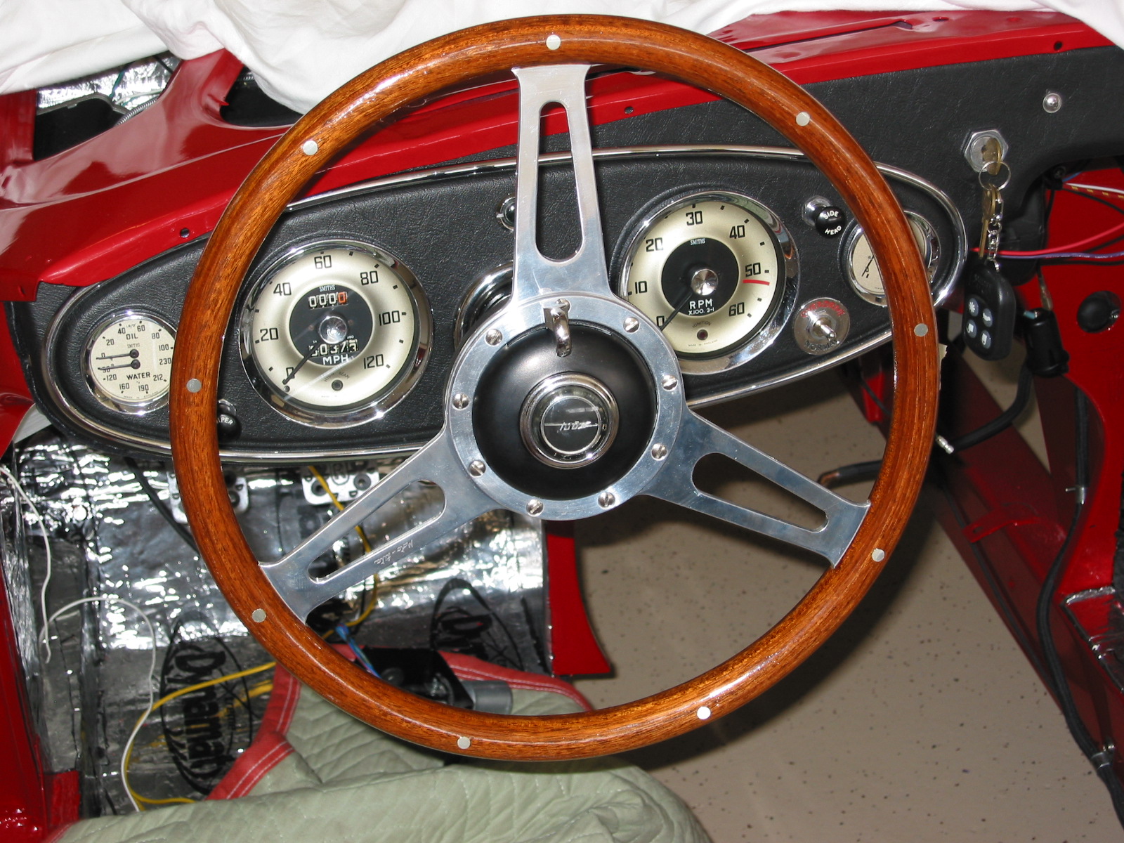
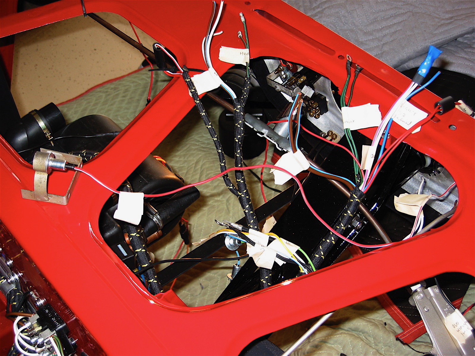
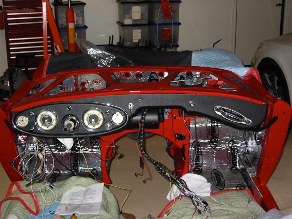
I began the wiring of the dash instruments, gauges and switches with the water temperature and oil pressure gauge and moved across the face of the dash from left to right with the exception of the speedometer and tachometer which were left until the end. The openings for these two instruments provide access to the back of the dash.
Spaghetti
The gauges/instruments were all rebuilt by MOMA and they did a beautiful job.
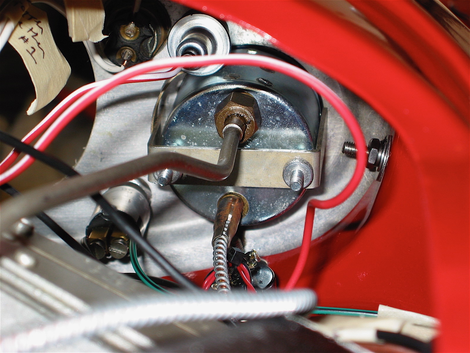
Before connecting the oil pressure gauge I inserted a new small leather washer that prevents oil from dripping on the driver’s leg! The washer was available from British Car Specialists.
The following is a summary of the wiring connections I made. Although this worked successfully for me, in no way do I suggest that this listing is a substitute for the diagram in the workshop manual. Anyone wiring their own vehicle should consult the manual for proper direction.
Ignition Switch #22 – Brown/Blue wire to right terminal #1; two white wires to the left terminal #2, twist together.

Ignition wiring
Tachometer – Yellow and White wires to the tach light bulb; black double wire is the ground for the tach.
Fuel Gauge #32 – Two solid green wires to terminal B; one green/black wire to the T terminal; red/white wire to fuel gauge light bulb.
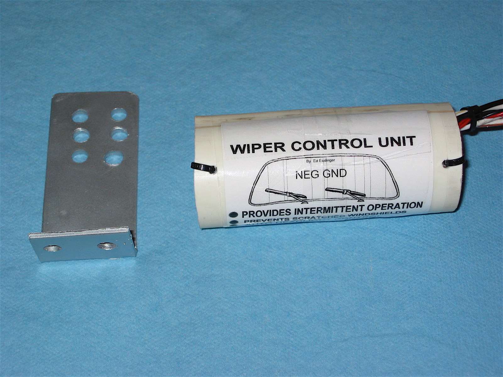
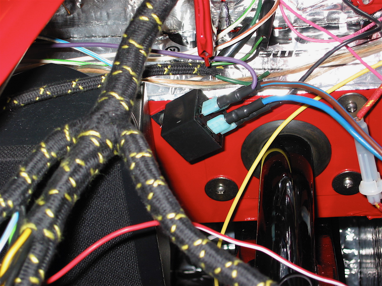
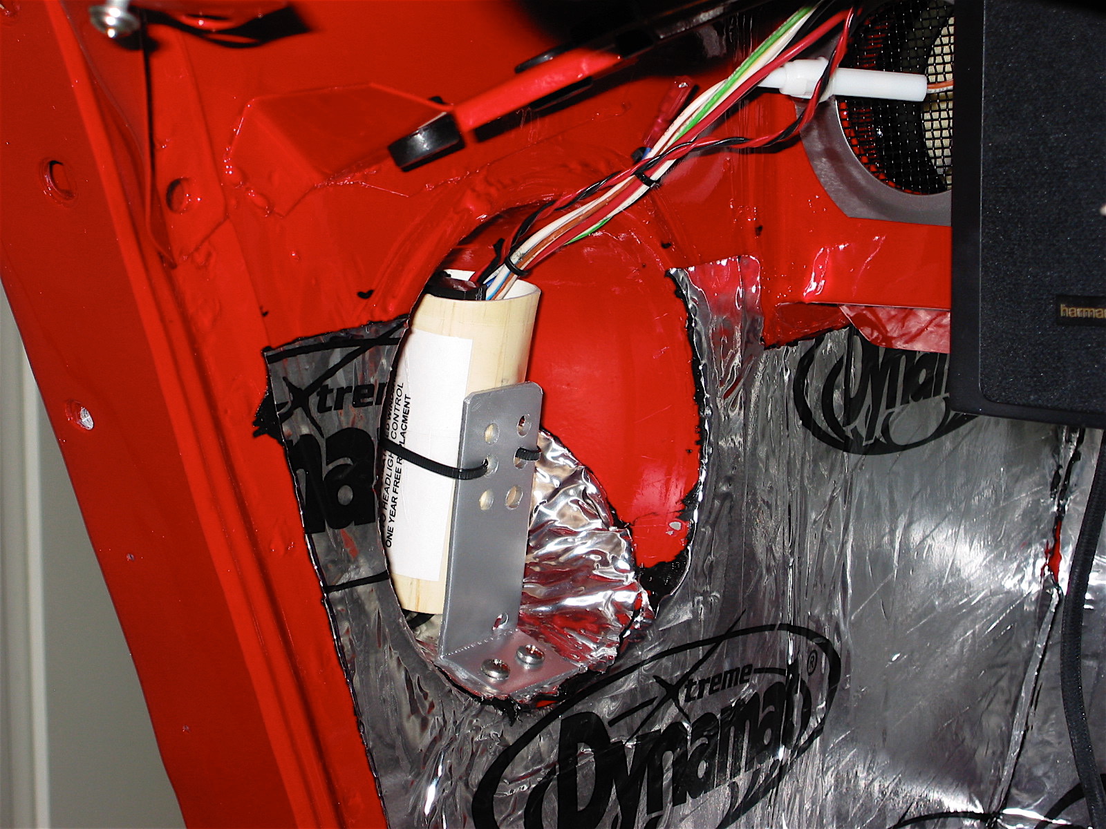
Light Switch #25 – Blue wire to the S2 terminal; two brown/blue wires to the A terminal twisted together. The wiring to this switch was modified to permit the intermittent wiper control module to also turn on the lights when the wipers are activated. This simply required running a blue wire from the module’s relay to the S2 terminal, and running an additional brown/blue wire from the relay to the A terminal on the light switch. Details on this assembly were provided in the week eight blog installment. I also installed an in-line fuse into the red wire leaving the S1 terminal.
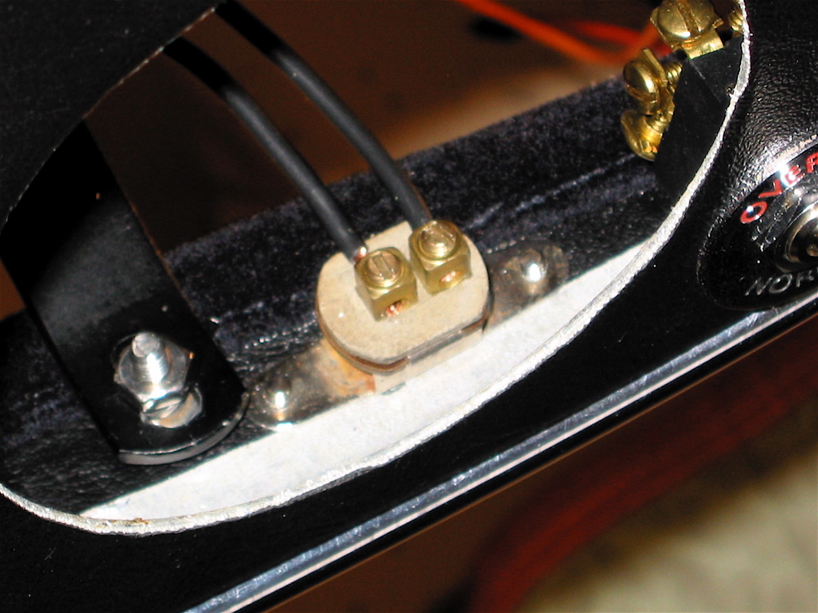
Overdrive Switch #39 – See the details in Heater switch below.
Flasher Warning Light #24 – Light green wire bulb
Speedometer #30 – Light blue/white wire light bulb. Two black wires to ground.
Wiper Switch #27 – These connections are modified to accommodate the intermittent wiper control. The white/yellow wire from the wiper control module is connected to terminal #1 on the dash wiper switch (replacing the black/green wire.)
The black wire from the wiper control module is twisted together with the black wire from the wiring harness and connected to terminal E of the wiper switch.
Starter Button #23 – two white wires twisted together to terminal #1; one white/red wire to terminal #2.
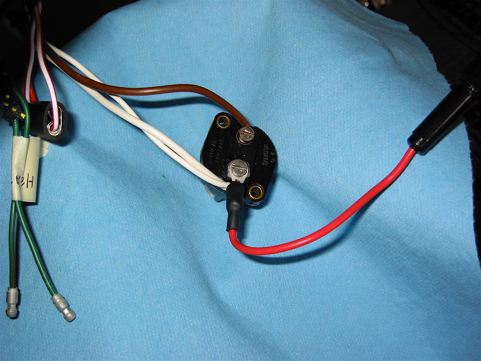
Water/Oil Pressure Gauge – red/white wire light bulb
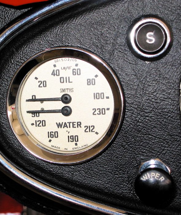
temp & oil pressure gauge

temp and pressure gauge
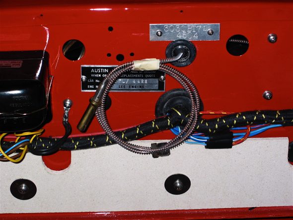
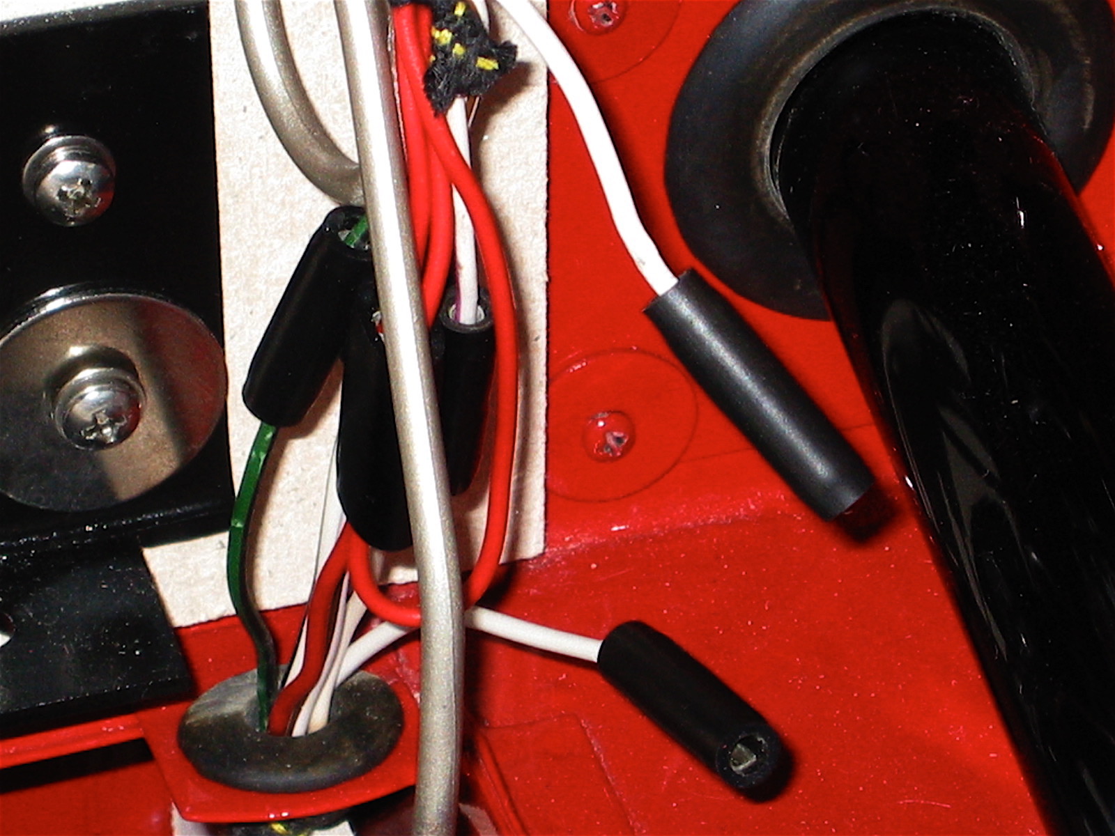
capillary tube for water temperature
Panel Lamp Switch #34 – I decide to leave the panel lights on all the time which made the panel light switch available to be used to control the auxiliary driving lights.
Panel Switch 2
The single red and double red/white wires originally screwed to the panel light switch were connected together with bullet connectors and a double rubber connector sleeve.
panel lights linked
The ground is used in the auxiliary light wiring system to complete or break the circuit. A black wire from the relay is connected to the panel lamp switch and then a black wire is connected from the other terminal on the panel lamp switch to a ground connection on the firewall.
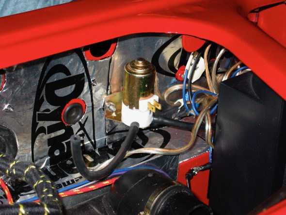
Heater – I am using a “modern” heater to replace the Smith’s unit under the dash. The new unit was available from Cape International. It uses a two speed fan that is internal to the unit. The Overdrive Switch is not used for that purpose on my car since I am using a Smitty conversion Toyota 5-speed gearbox. Therefore, I replaced the switch with a DPDT switch and used it for the heater control. The red wire (high speed) was fastened to one terminal of the switch, the orange wire (low speed) was fastened to the terminal on the other side of the switch, and the yellow wire from the supplementary fuse panel was connected to the central terminal on the switch to provide power to the unit. So I ended up with a convenient heater control without having a change in appearance of the dash or locate a switch in some hidden place.
Smith’s Heater Blower Fan – Since the new heater contained its own fan, the Smith’s Blower was available to be used as a blower for fresh air to the passenger (right side) compartment. I will discuss it further when I come to the installation of the new fresh air supply components.
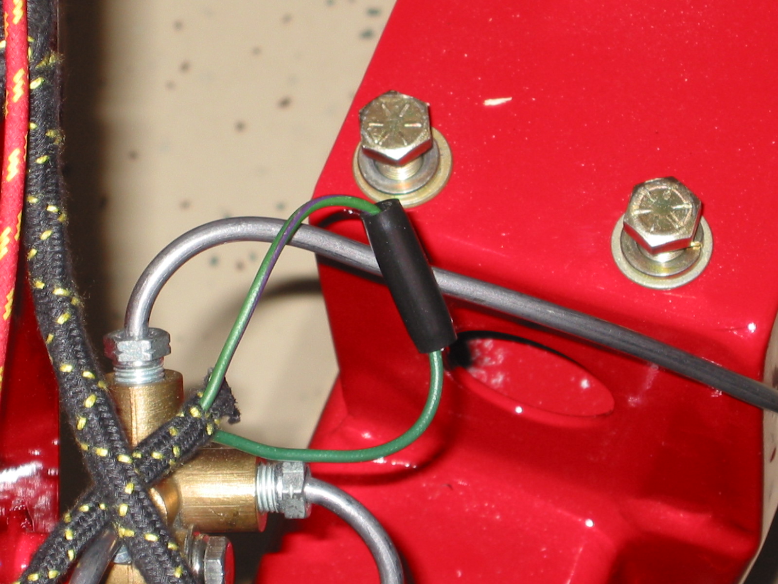
Heater Switch #26 – The green/brown wire to the black bullet wire connector on the switch. The green wire to the black bullet wire connector on the switch.
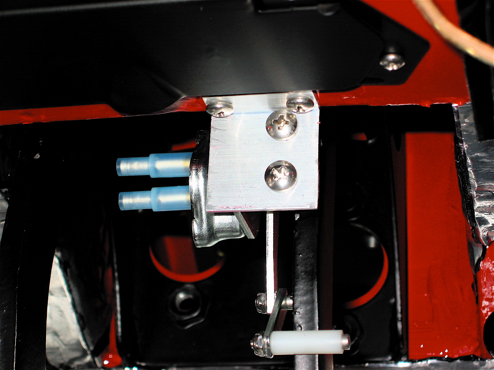
Windscreen Washer Pump – I read a technical article by Stu Brennan, an owner of a Sunbeam Tiger, who had converted his hand activated pump windscreen washer to an electric washer. I like the idea because he put the electric switch in the aluminum canister thereby eliminating the need to install an additional switch somewhere. Since the washer in the Tiger is the same as the one in the Healey, I decided to give it a try. These links provide Stu’s instructions for his car and my interpretation for the Healey. The fused red wire is connected to the purple switched wire from the supplementary fuse panel. The other red wire from the washer canister connects to the washer pump. Elect Washer Pump Comp and Rose Elect. Washer Pump Comp.
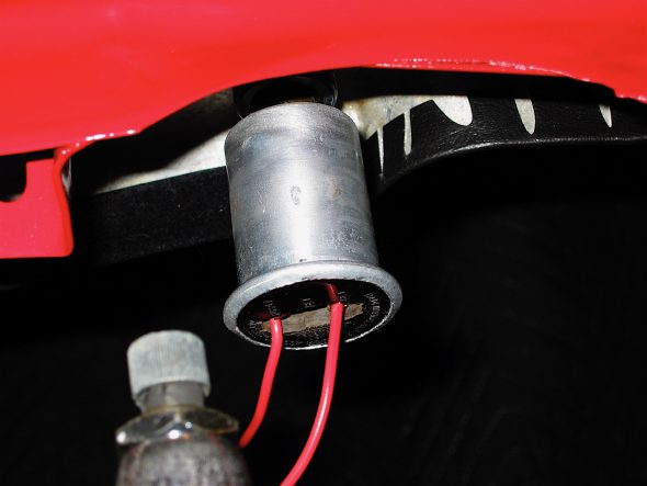
electric windscreen washer 2
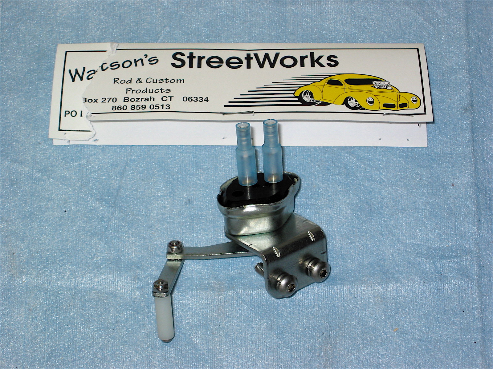
Washer Pump
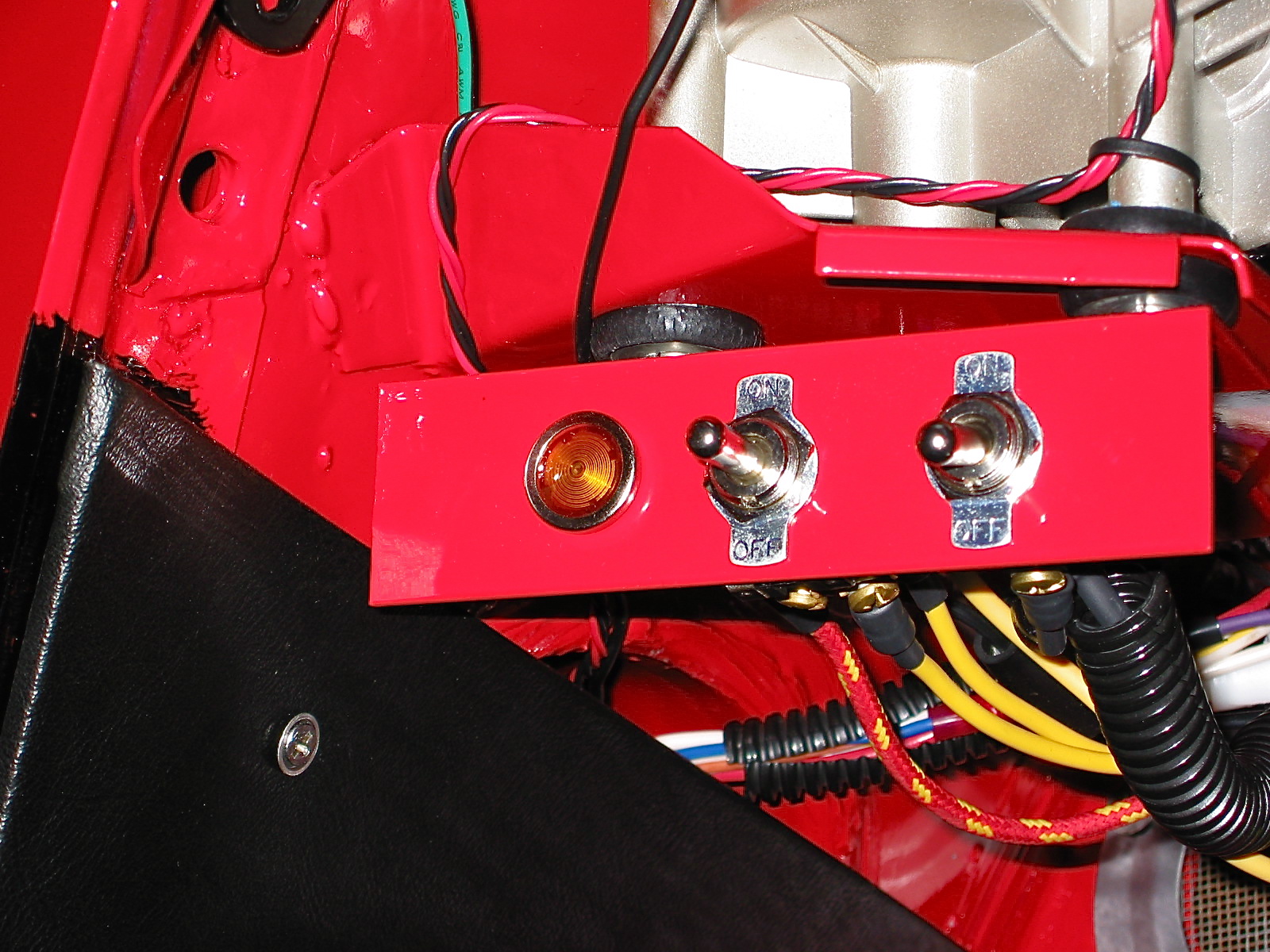
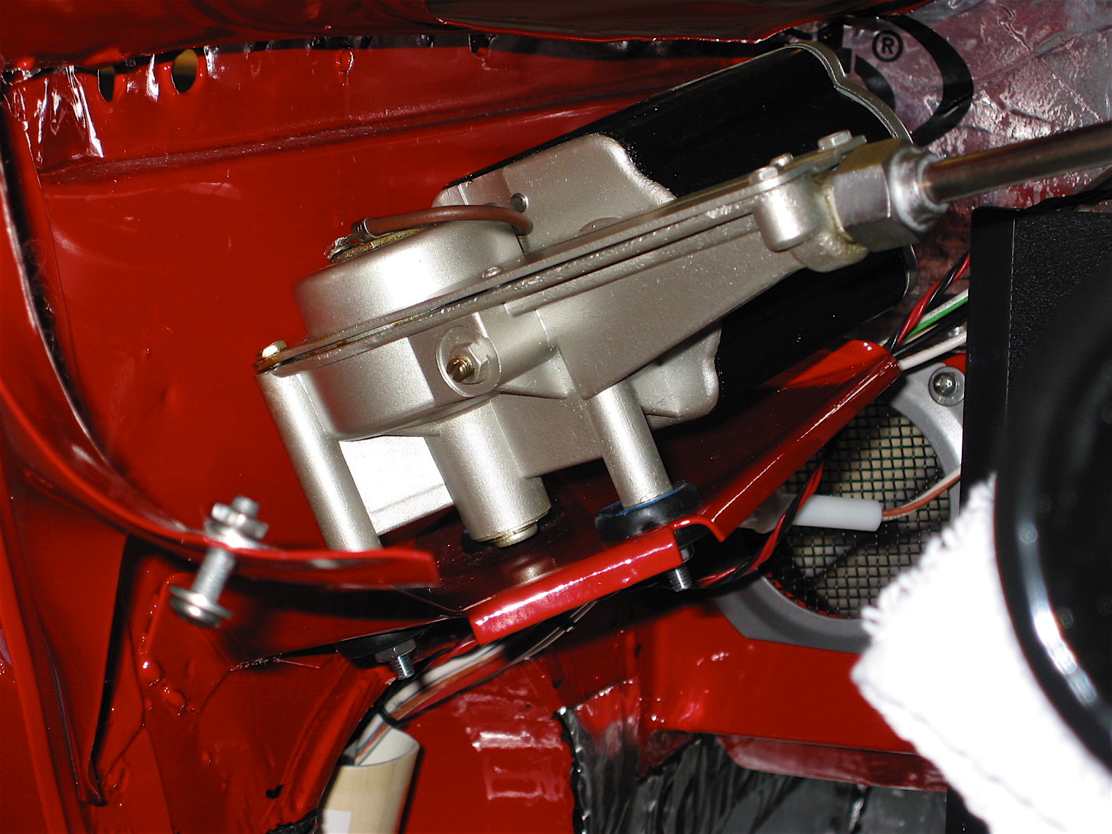
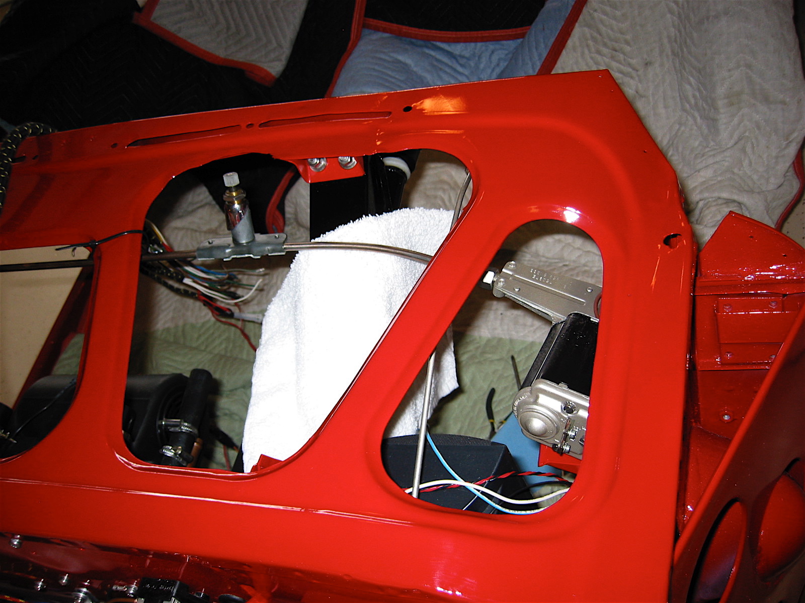
Toggle Switch Panel – Try as I did, I could not find enough places to provide switch controls in original mountings (overdrive switch and panel lamp switch as examples) for every accessory or modification that I wanted to add, so I made a small panel out of aluminum stock (1 1/4″ L stock) to house two toggle switches and an indicator light for the auxiliary lights.
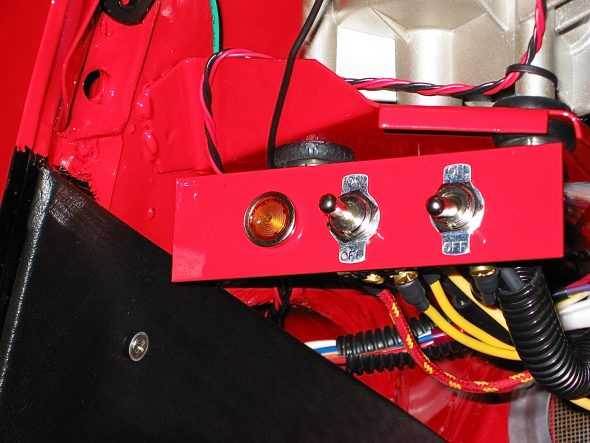
Toggle switch plate
I mounted the switch panel to the front two screw posts for the wiper motor. I will still successful in mounting the switches without drilling any new holes in the car! The bracket is painted red to make it less obvious, although it is concealed pretty well anyway.
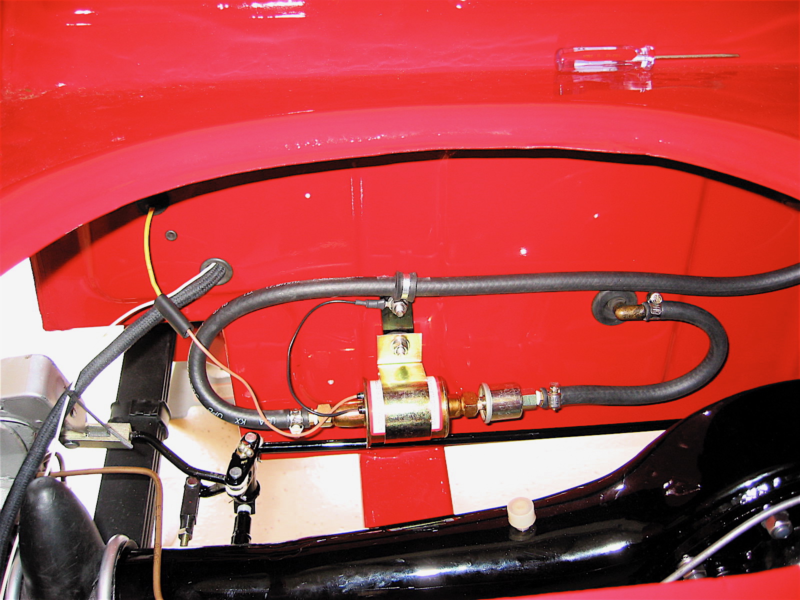
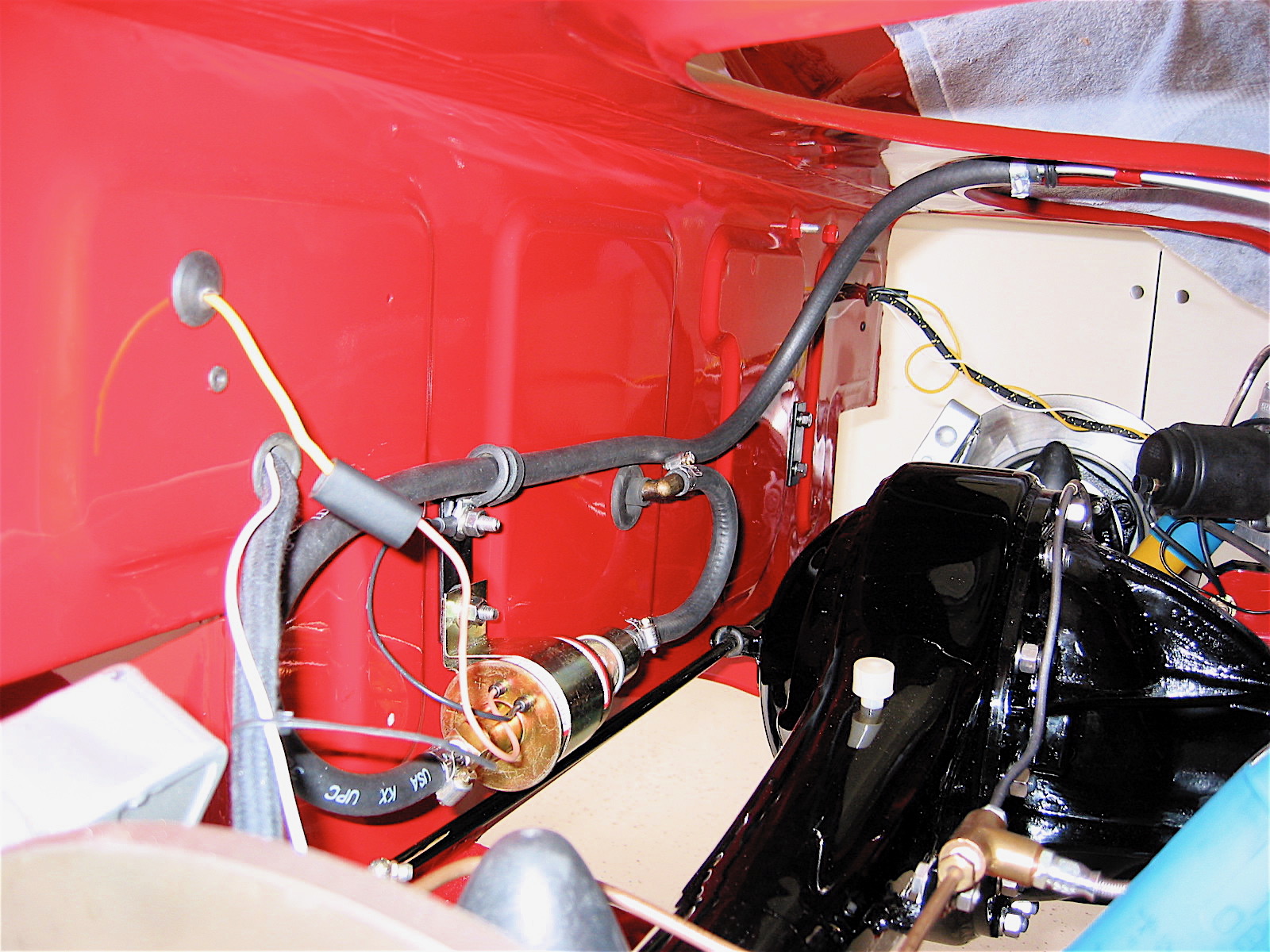
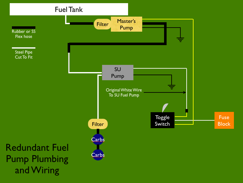
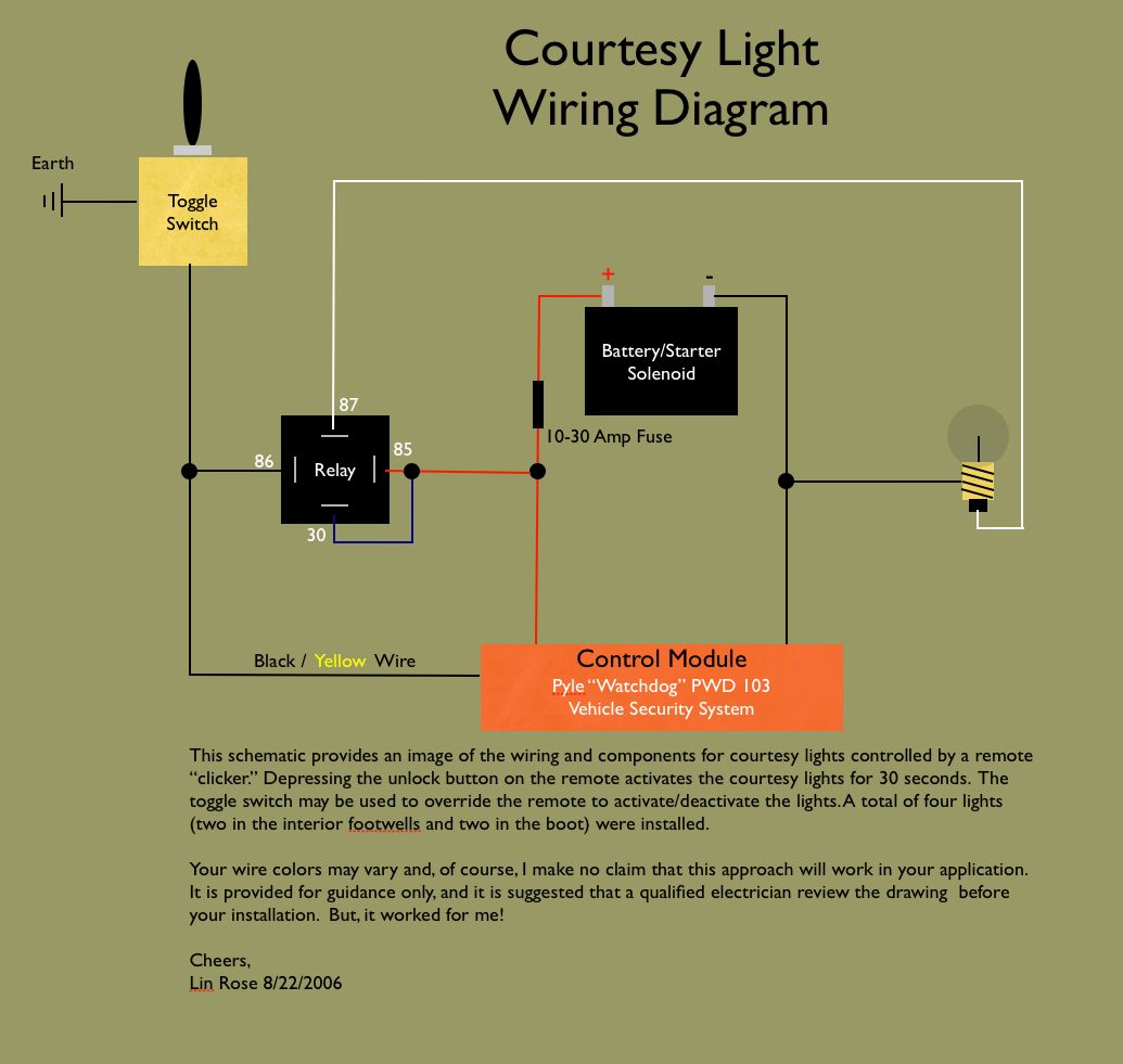
One of the toggle switches will be used to override the remote control for the interior/boot courtesy lamps. Using the remote “clicker” the lights stay illuminated for only 40 seconds, but the toggle switch can be flipped “on” to leave the interior lights on until flipped “off.” The second toggle switch will be used to activate the redundant fuel pump when needed. In the “up” position the original-type SU pump is activated. In the “low” position the second Carter pump is activated. In the center position neither pump is activated – a good ani-theft device!
Finally, an alert lamp is include in the panel that notifies the driver that the auxiliary driving lights are on.
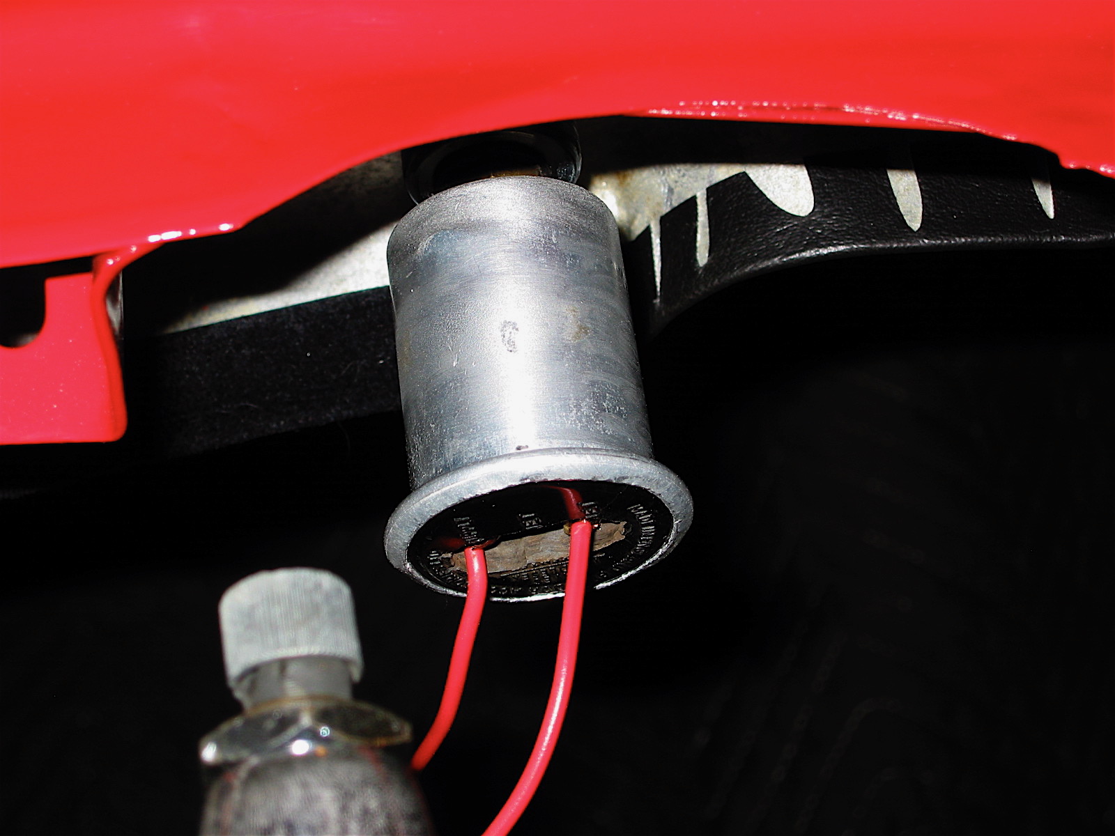
Interior Courtesy Lamps – Purists will get another chuckle out of my addition of remote control courtesy lamps in the footwells of the interior and in the boot. Again, I did not want to drill any holes in the car for door jam switches so I thought, “why not use electronic remotes used in modern cars to unlock doors, open boots, and set off alarms to activate the lamps?”

Courtesy light right
The remote control system I acquired from Pyle was about $40.00. It included two remote “clickers,” the control module, and the wiring. I grossly underutilized all that the Pyle system makes possible, but I was after simplicity. I just cut off all the extra wires, but I can imagine a few other very practical uses. The button on the remote typically used to unlock the car (obviously not needed on a BT7 roadster) is now pushed to activate the interior/boot lamps. As I approach the car at night, I can click the remote and my interior lamps will come on for 40 seconds and they extinguish on their own with not other action required. As noted above, a toggle with is also wired-in to control the lamps.

Courtesy Light Install
The lamps are some fairly primitive incandescent fixture purchased from Victoria British, part #15-642, but sine they are not easily seen I was not too concerned about their physical appearance. I made some simple brackets and mounted them in the footwells on each side of the car, along with the control module and its relay. Again, placement of the lights was determined by available mounting points so additional holes in the car were not required. A boot light adapted from a period license plate illumination lamp was also installed.
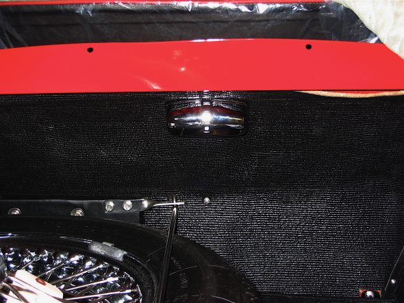
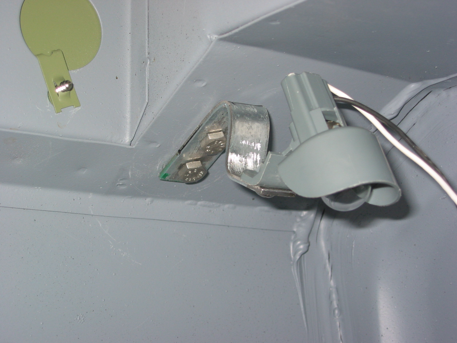
Boot light
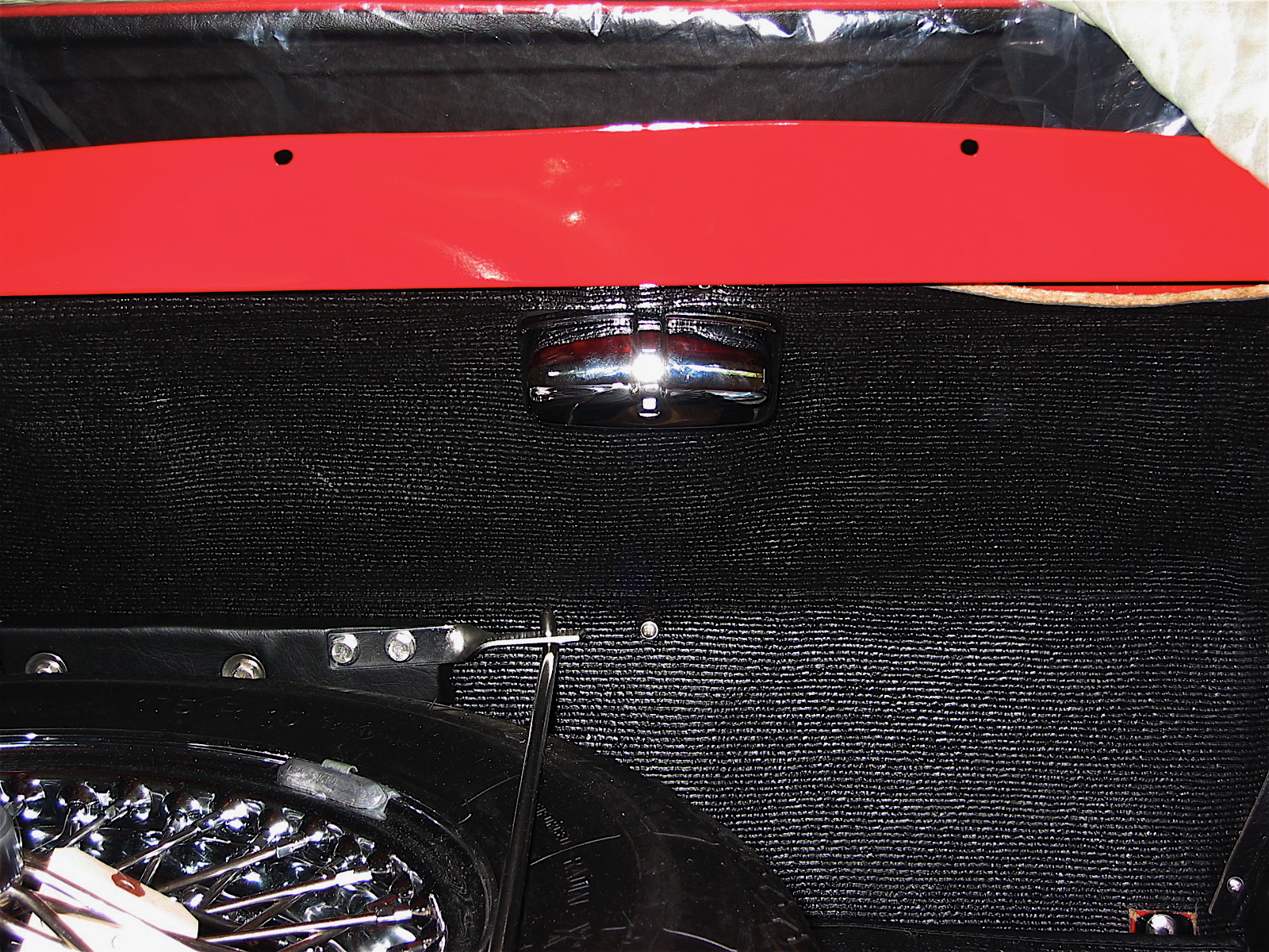
dash fascia