Steering Wheel
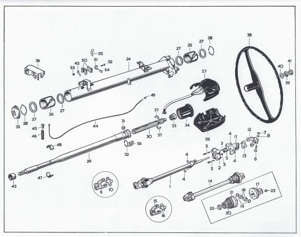
This is a diagram showing steering column components.
The disassembly procedure I followed is outlined below:
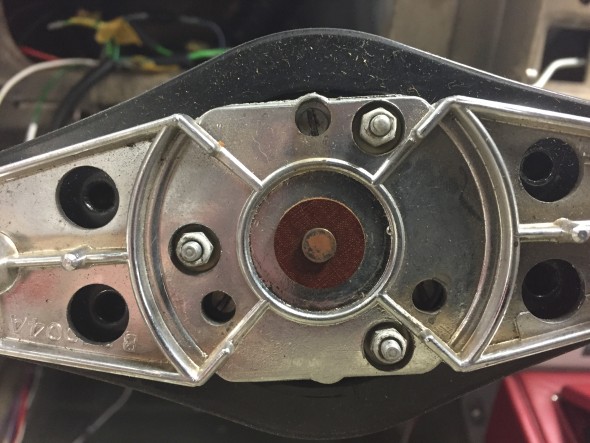
First I removed four slotted set screws from behind the steering wheel this enables the horn ring cover to be removed along with the horn push and return spring.
The horn ring assembly is held in place by three small nylock nuts (#6?) on studs. These nuts were removed and behind each nut was a nylon shouldered washer. The horn ring assembly is spring loaded so when the third nut is removed one needs to be careful not to lose the springs behind the assembly. After the three nuts and washers are loosened the horn ring can be lifted away.
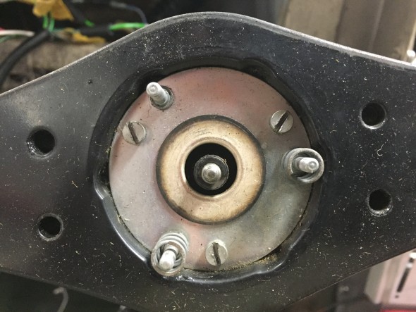
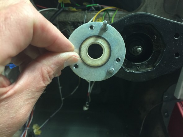
This reveals springs on two of the studs and a mounting plate held in place by three cheesehead machine screws. The springs were set aside and the three screws and slit washers were removed allowing the subsequent removal of the mounting plate with its three studs.
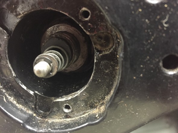
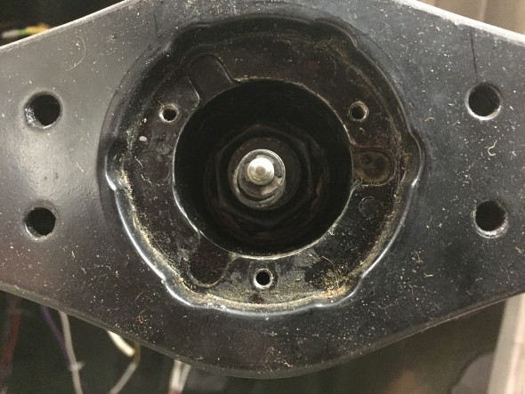
This revealed the horn button wire which contains the contact button, a spring, a small flat washer and a circlip holding the assembly together. a tubular black insulation piece is behind the wire assembly and slips into the shaft. It is NOT necessary to disassemble this horn contact wire in order to remove the steering wheel.
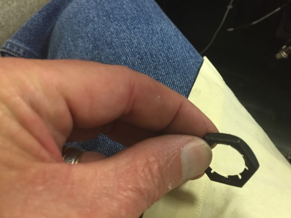
Also revealed was a locking Palnut on the steering shaft that was removed with a 15/16″ socket.
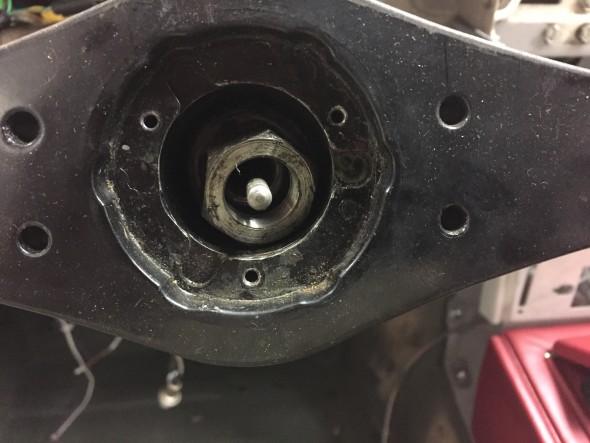
After removing the Palnut, the nut and special washer securing the steering wheel to the inner column shaft can be seen and removed. A 1 1/16″ socket was used. The steering wheel could be then be removed from the shaft.
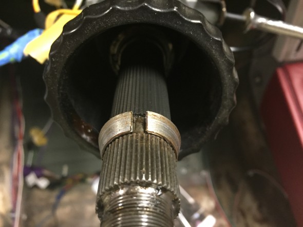
Care must be taken to not lose the two-piece split cone that seats the steering wheel on the shaft. These are revealed following removal of the steering wheel.

