The Big Healey Ten-Year Renewal Blog – last update 12/10/2020

Featured

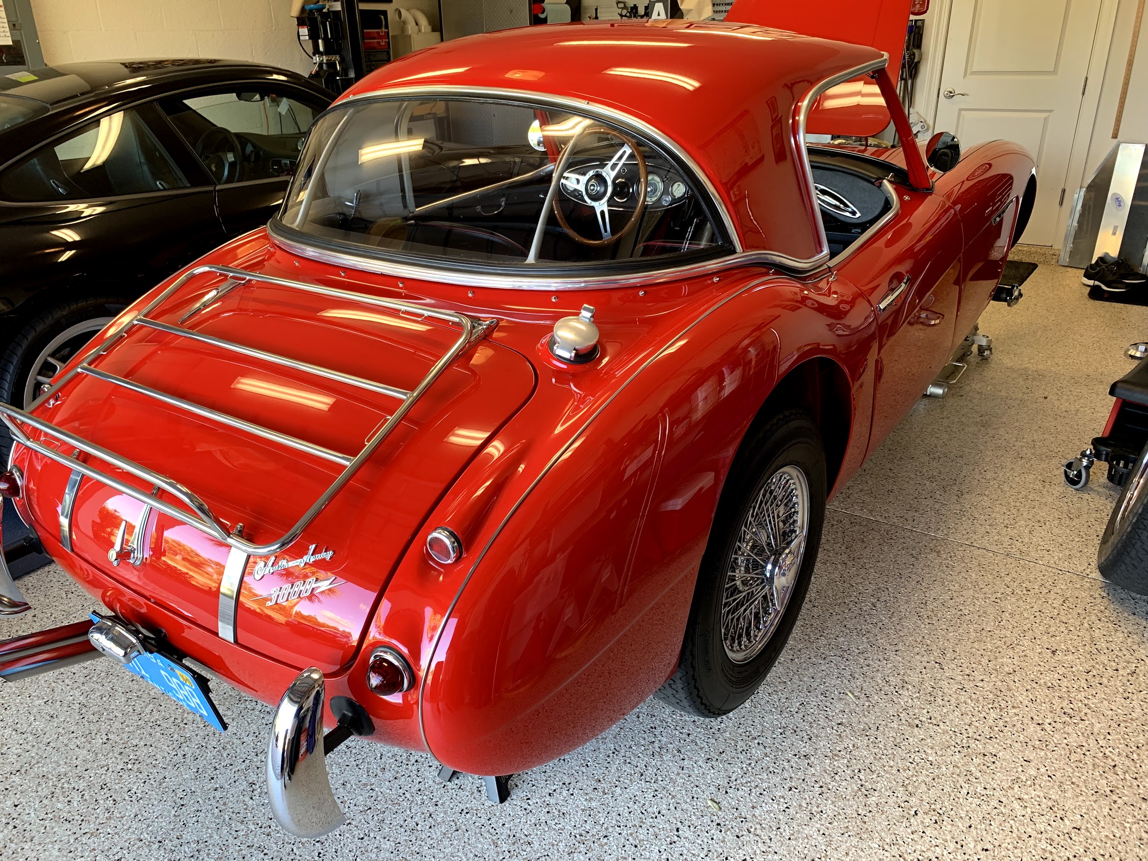
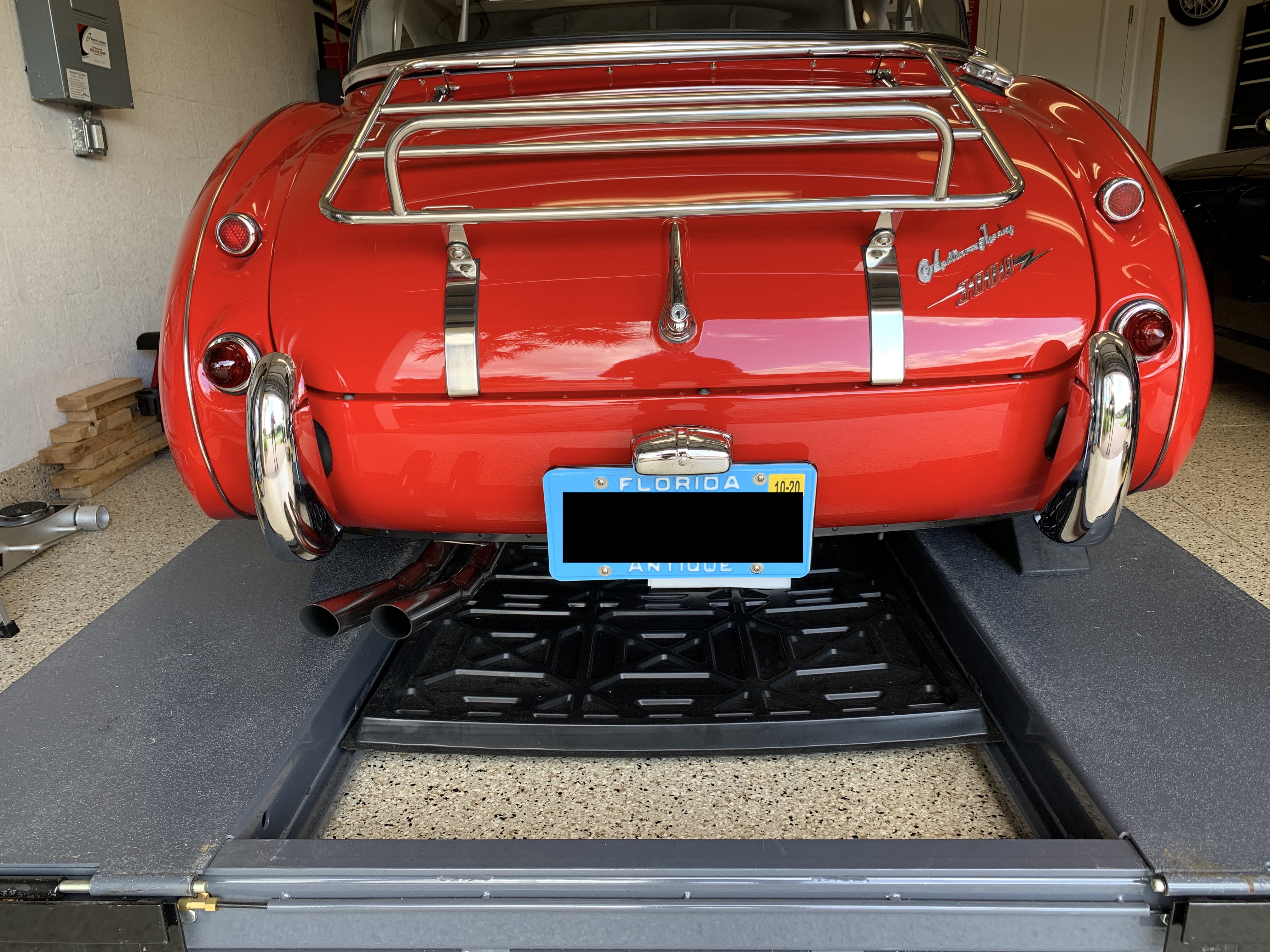
If you scroll down to the October 2018 entry to this Blog you can read about the motivation for what I then called the Ten-Year Renewal Project for my 1960 Austin-Healey BT7. True to my history with this car, everything takes longer than expected! While the care and maintenance of a classic car never ends, now in October 2020 I am going to proclaim that the Renewal Project has come to its conclusion.

The good news is that I have accomplished quite a lot and I am pleased to say that the Bloody Beast is running better than it has ever run while in my ownership, and that covers forty-nine years!

This website has a separate entry for all of the major renewal efforts, so one does not have to read through everything in order to obtain more information about a particular project. However, in no particular order, the following is a summary of all that has been accomplished in the past two years:

  • Greased all suspension, steering and handbrake grease zerks.
  • Installed a fresh smear of white lithium grease on door locks, bonnet catch and boot lock.
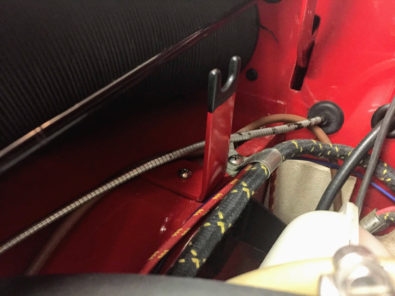
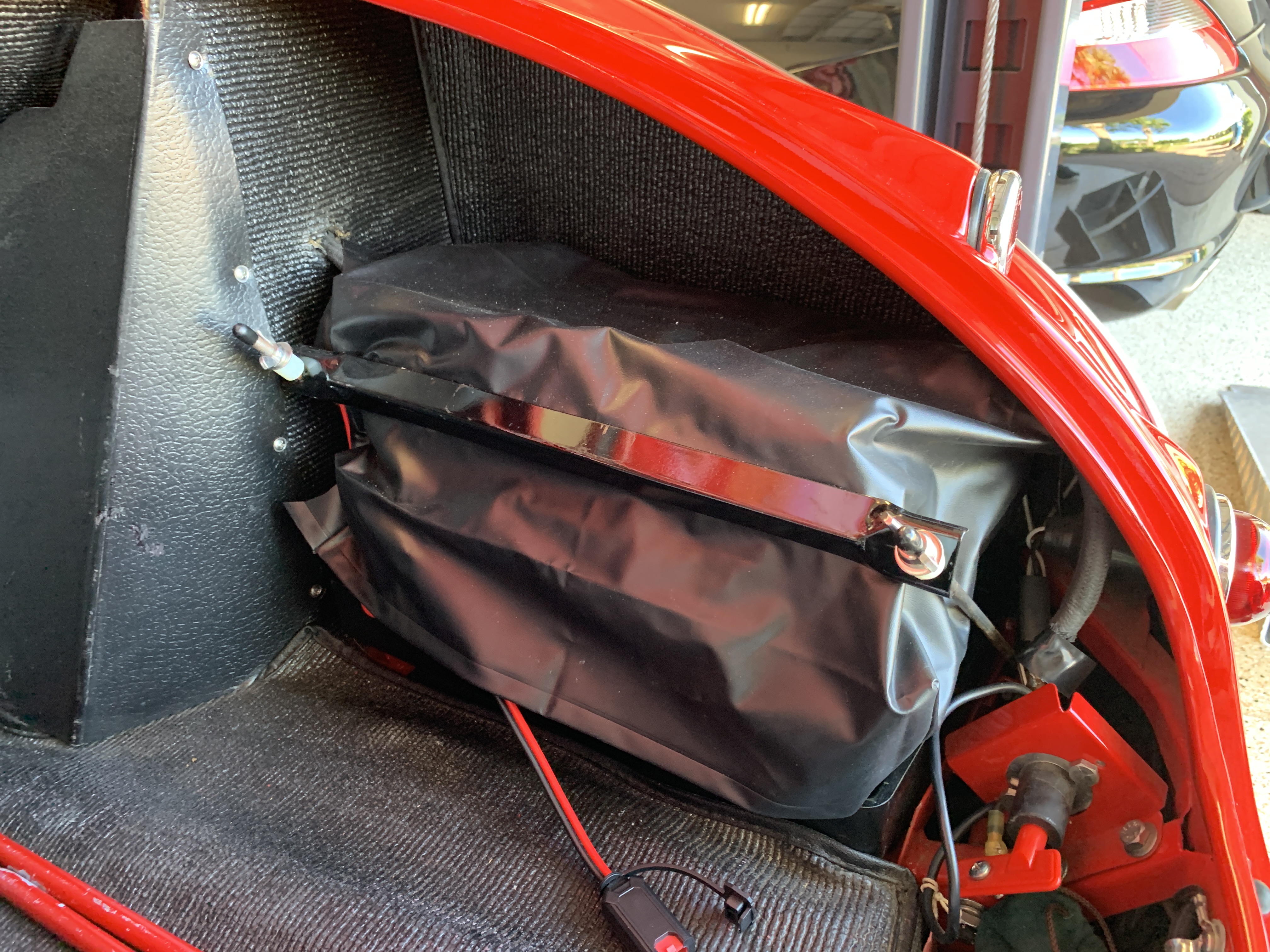
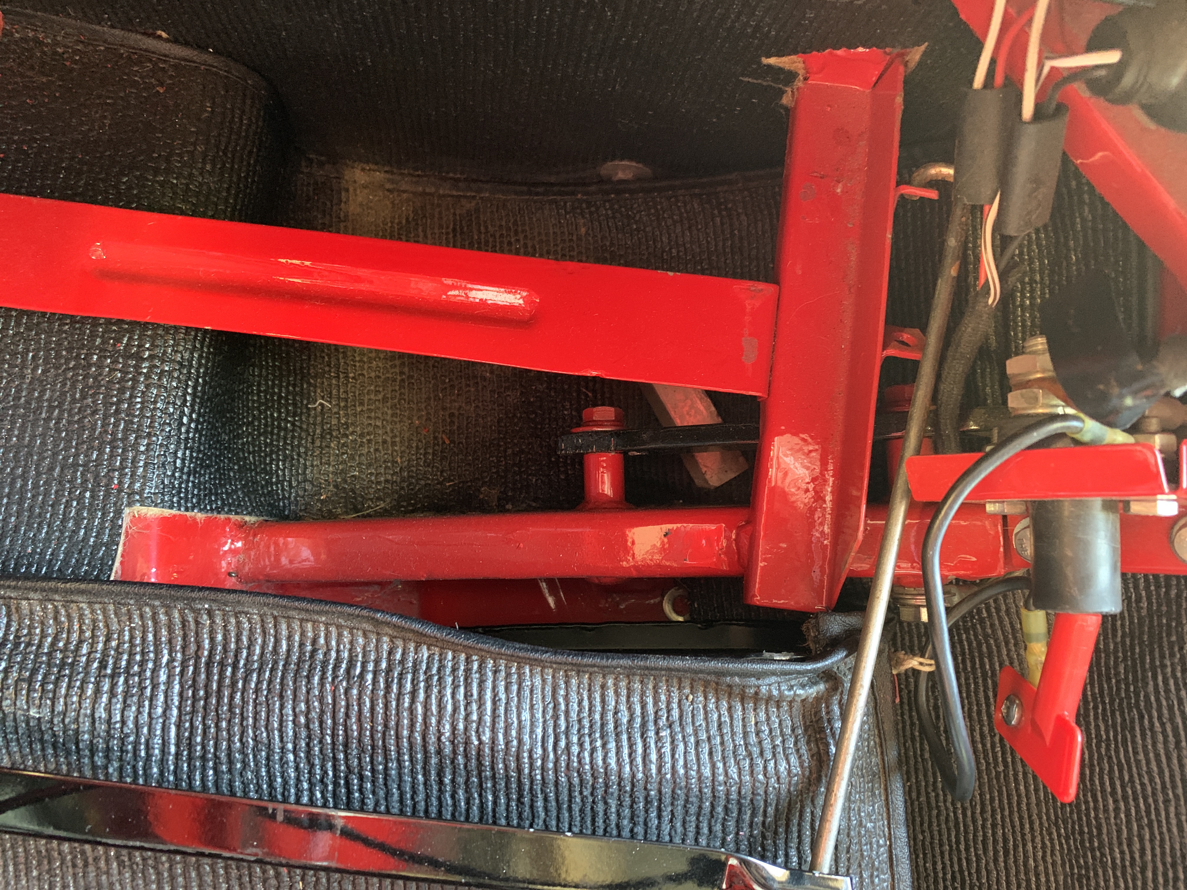
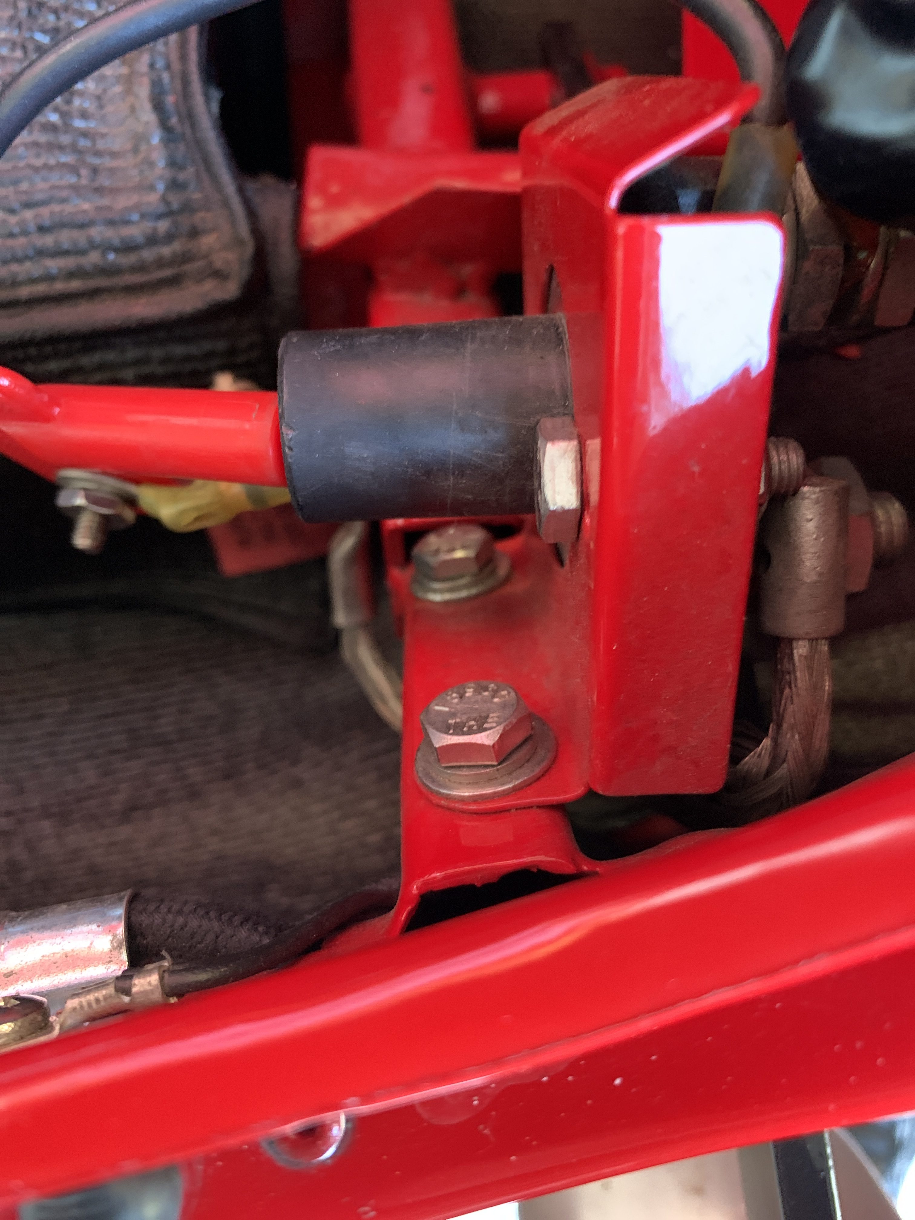
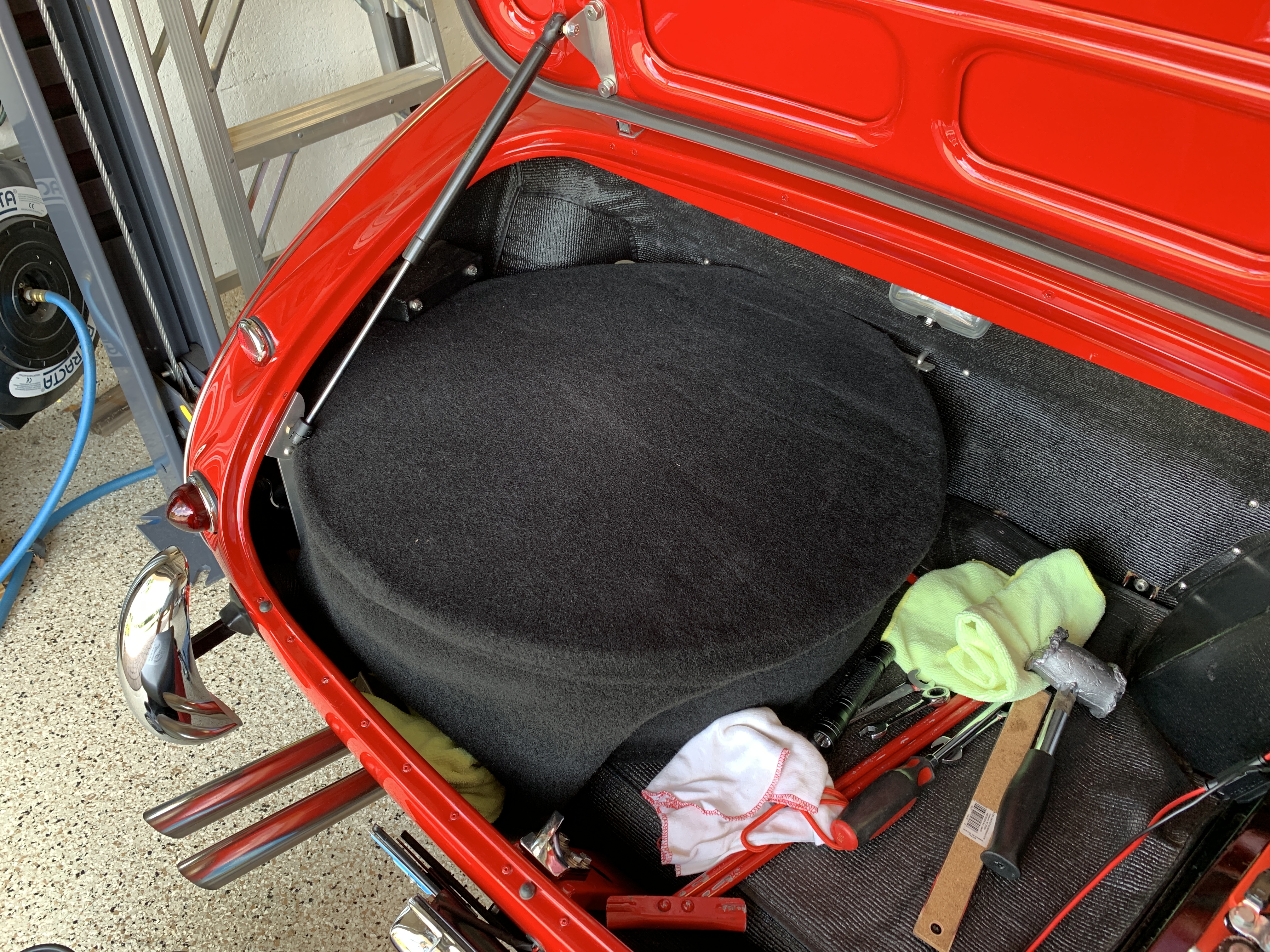
  • Checked the ground strap in the boot for tightness.
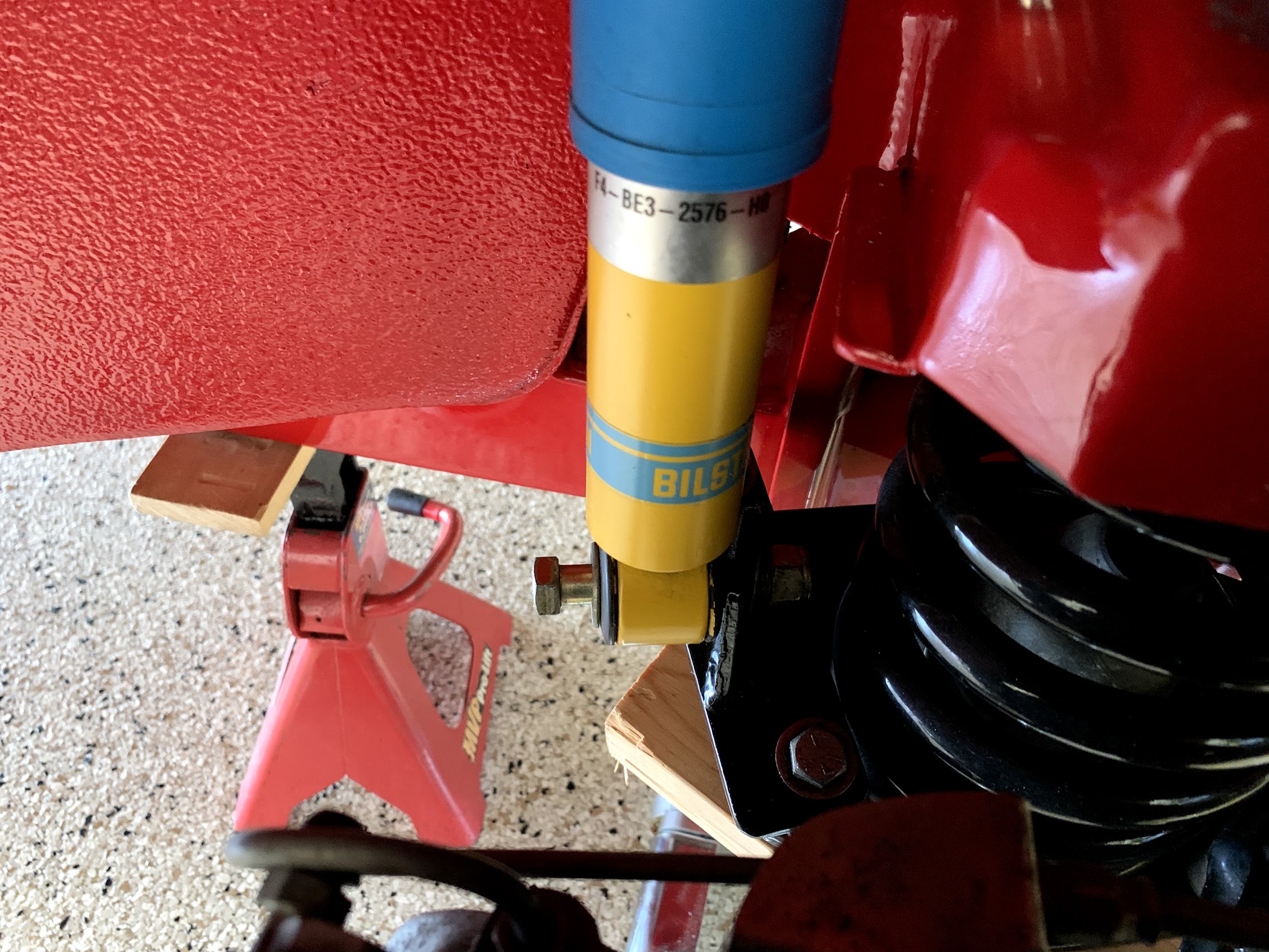
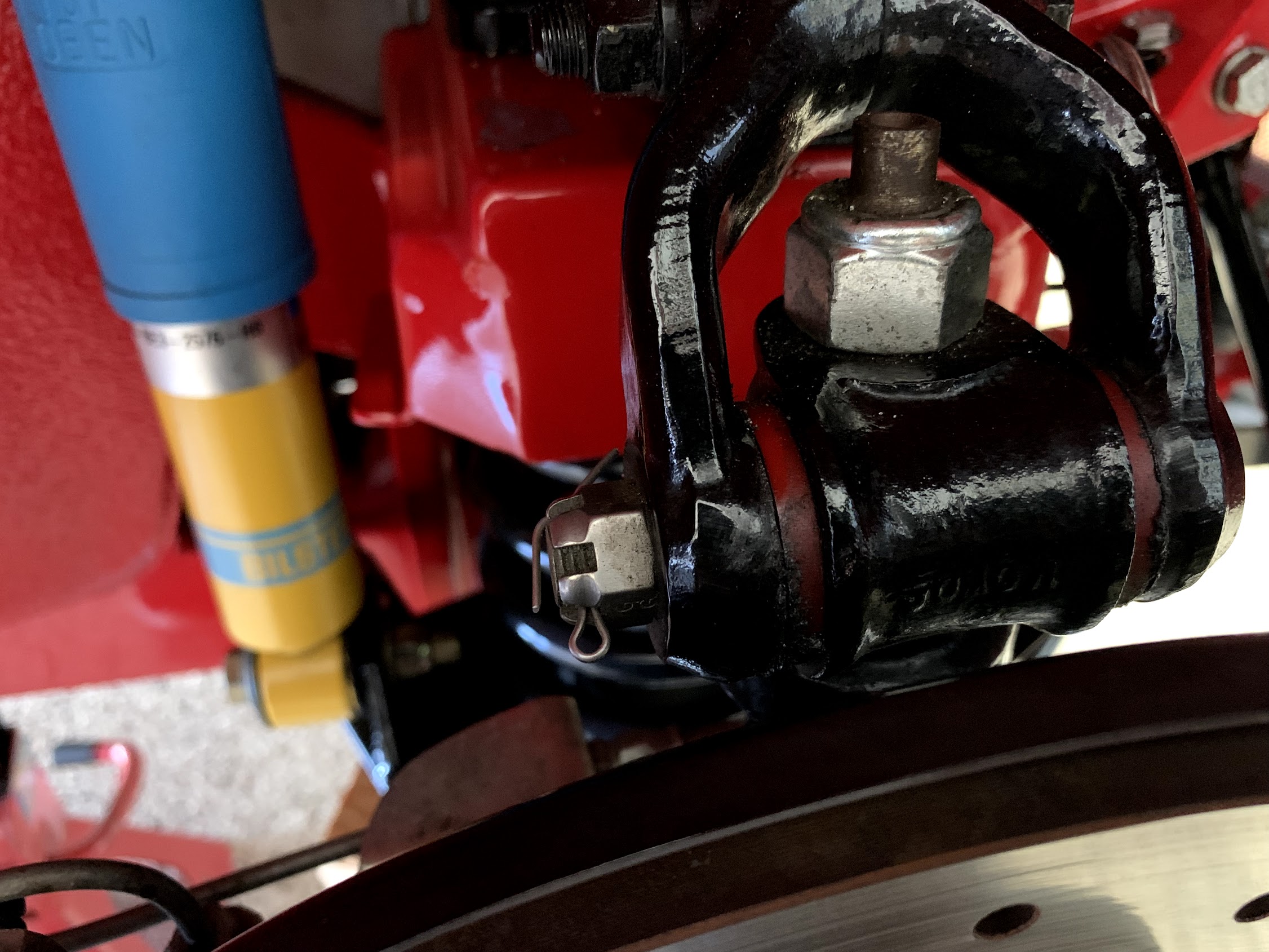
  • Checked tightness of engine mount and shock damper bolts.
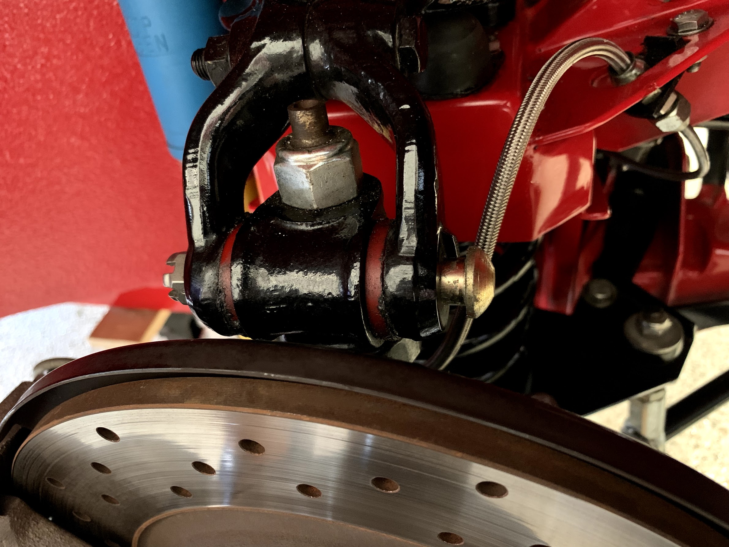
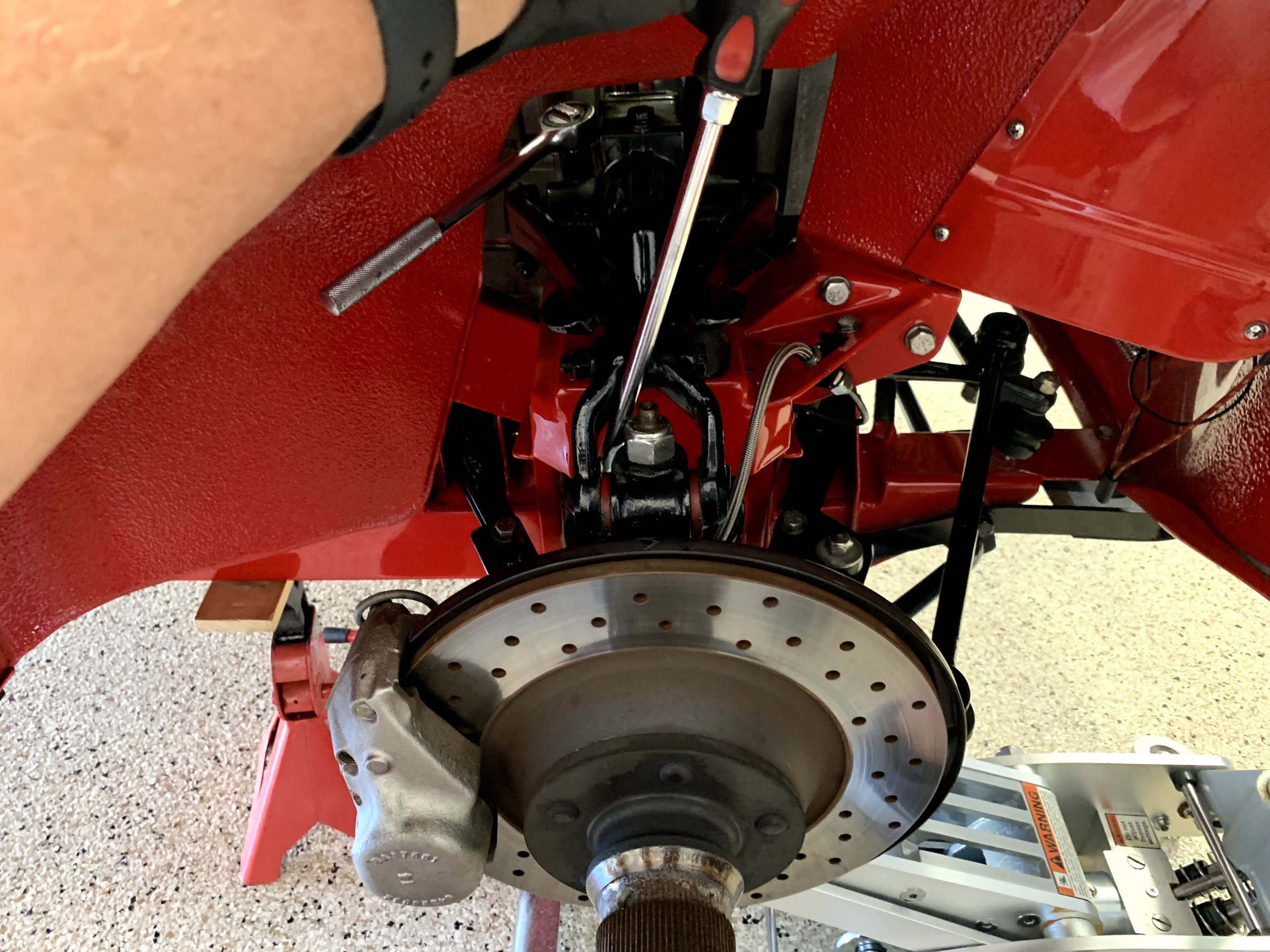
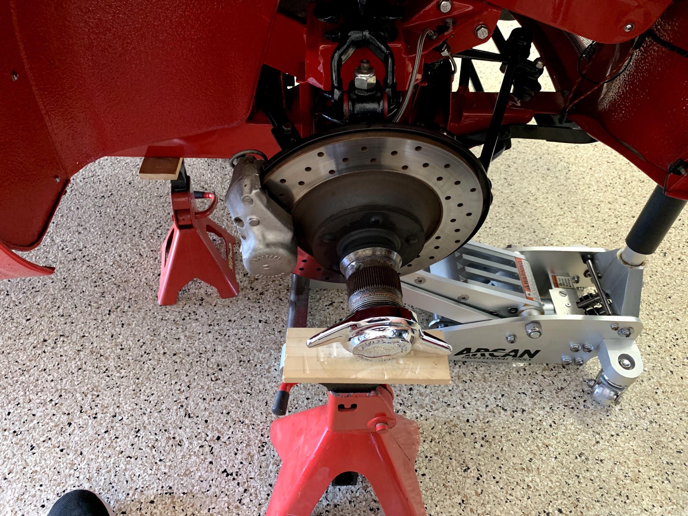
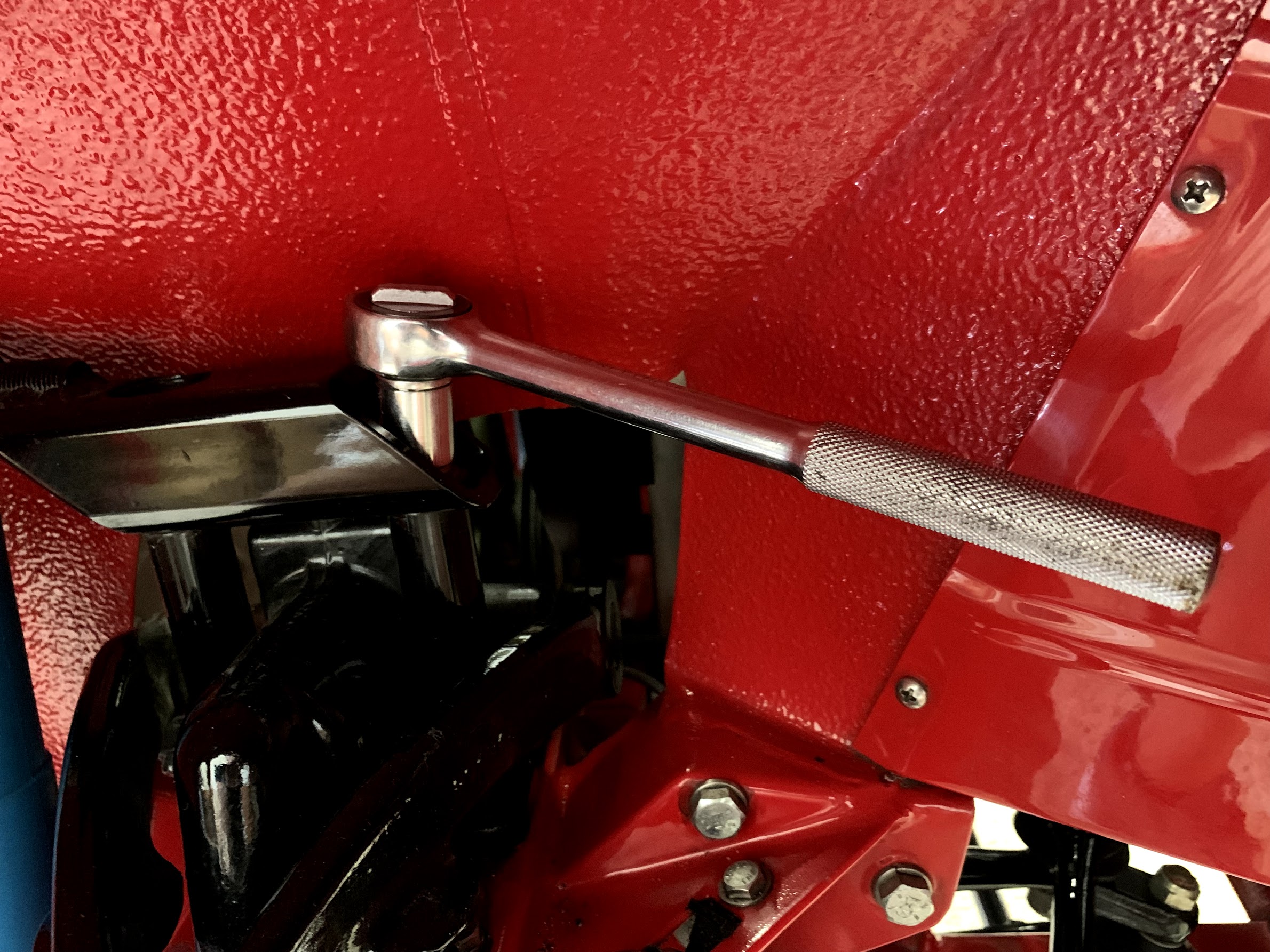
  • Checked rubber boots on on suspension ball joints.
  • Checked king pin wear.
  • Replaced fluids in gearbox, engine, hydraulic system, cooling system, rear differential. Replaced the Penrite oil in the steering box and idler with John Deere Corn Head grease to help prevent leaks.
  • Checked all dash lights for functionality.
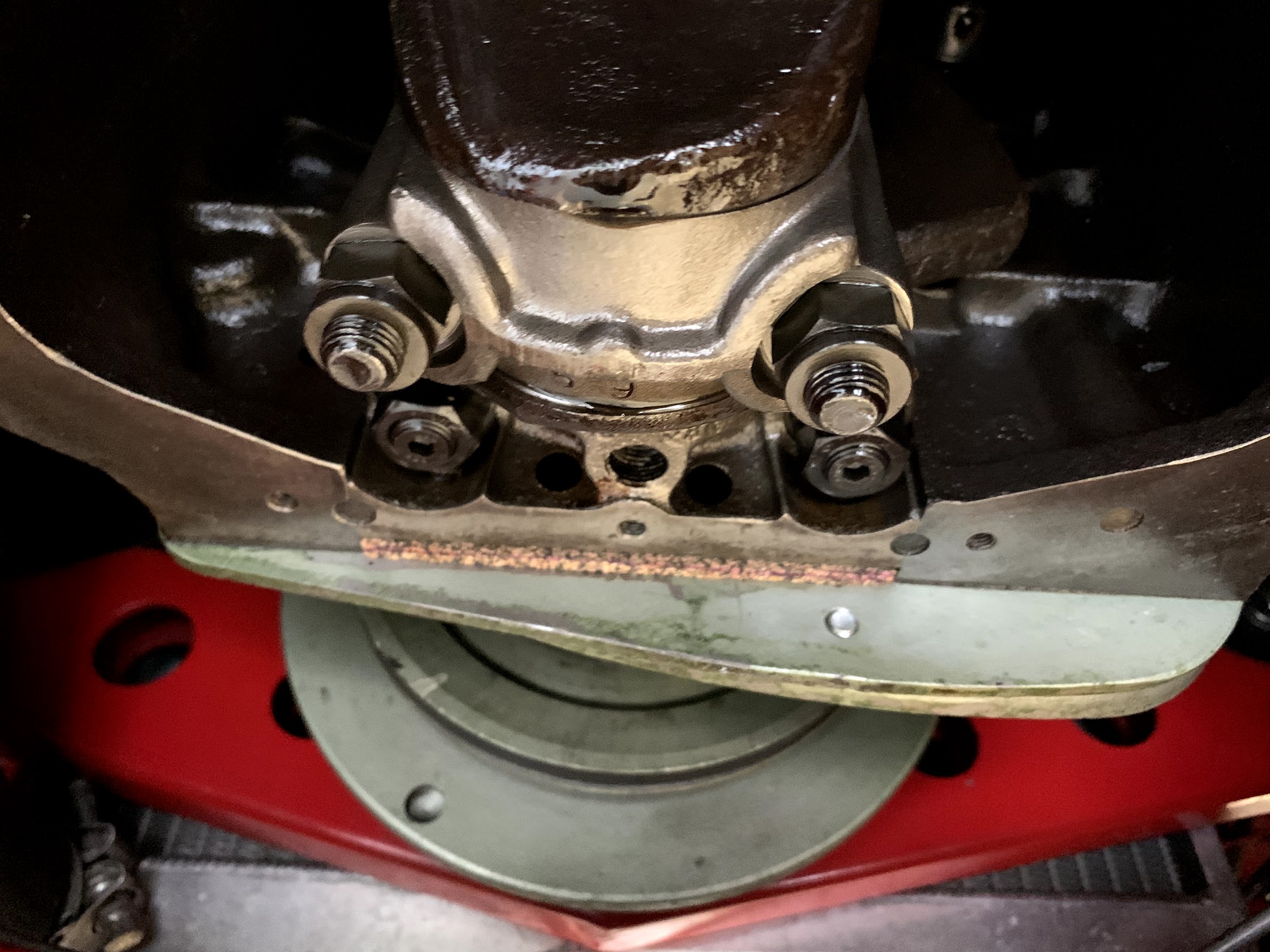
  • Checked tightness of prop shaft bolts/nuts at both ends of the shaft.
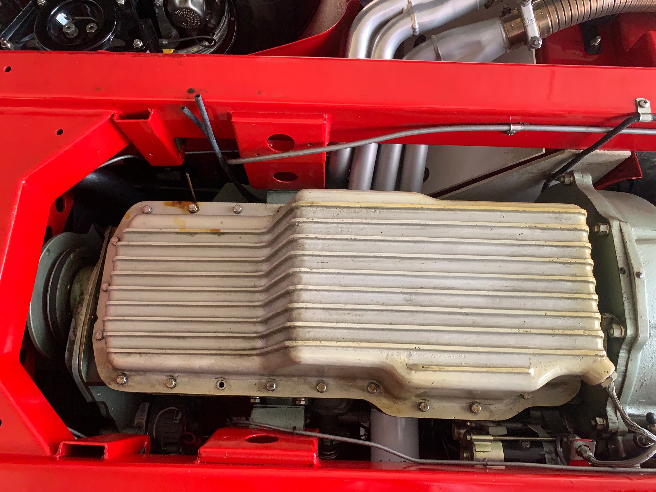
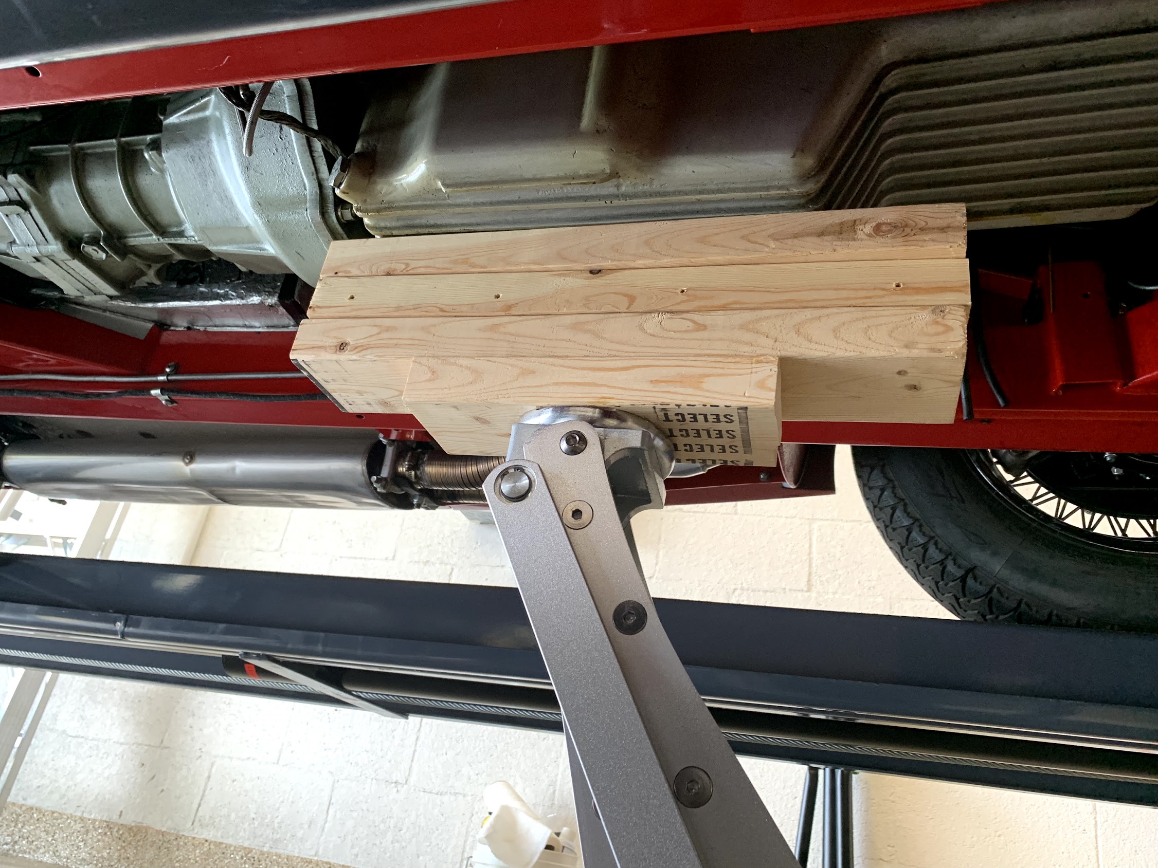
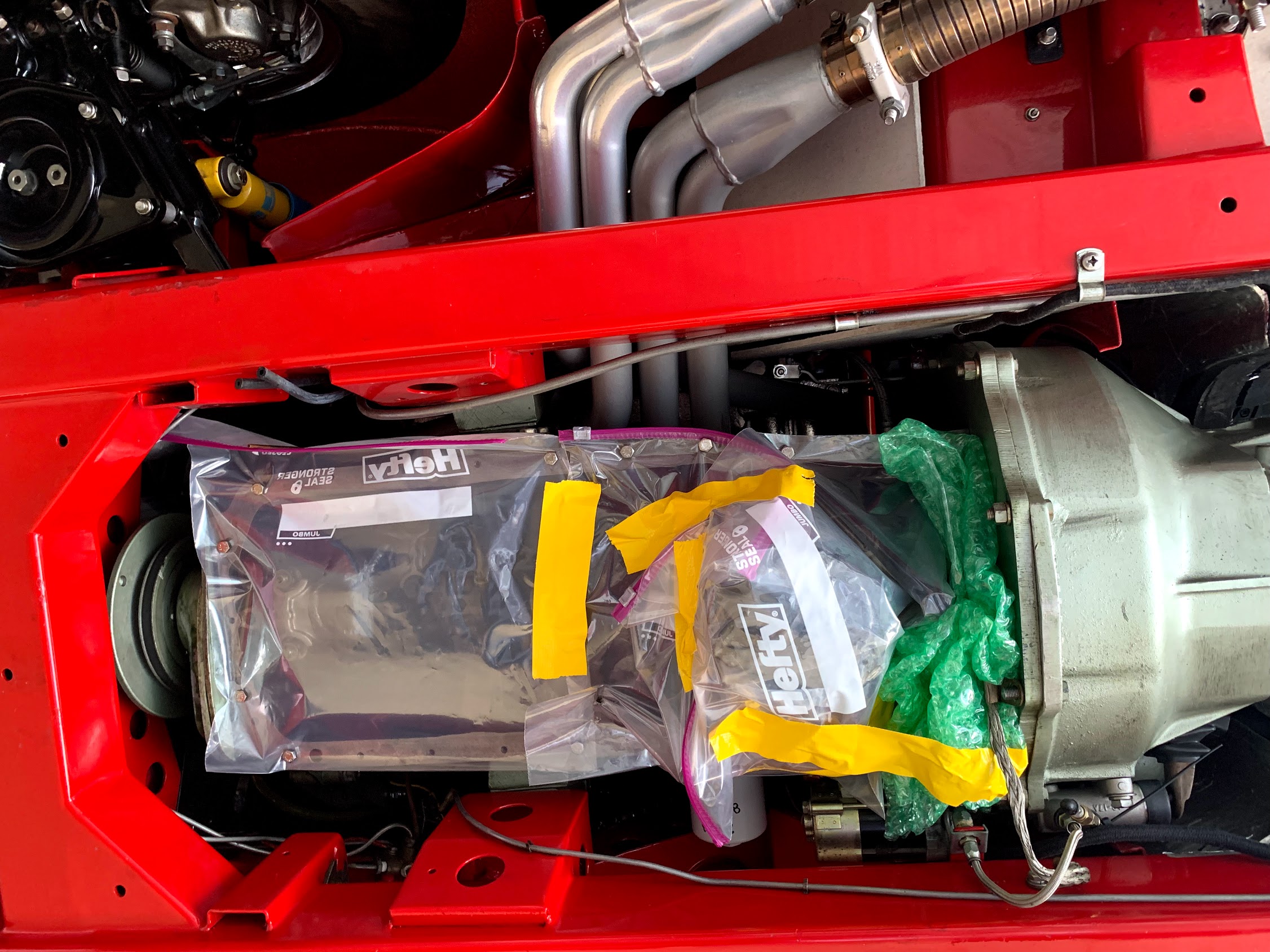
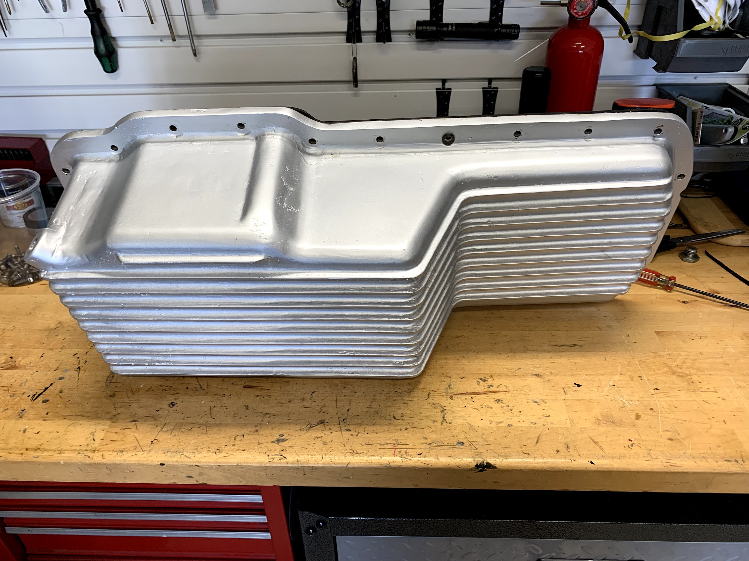
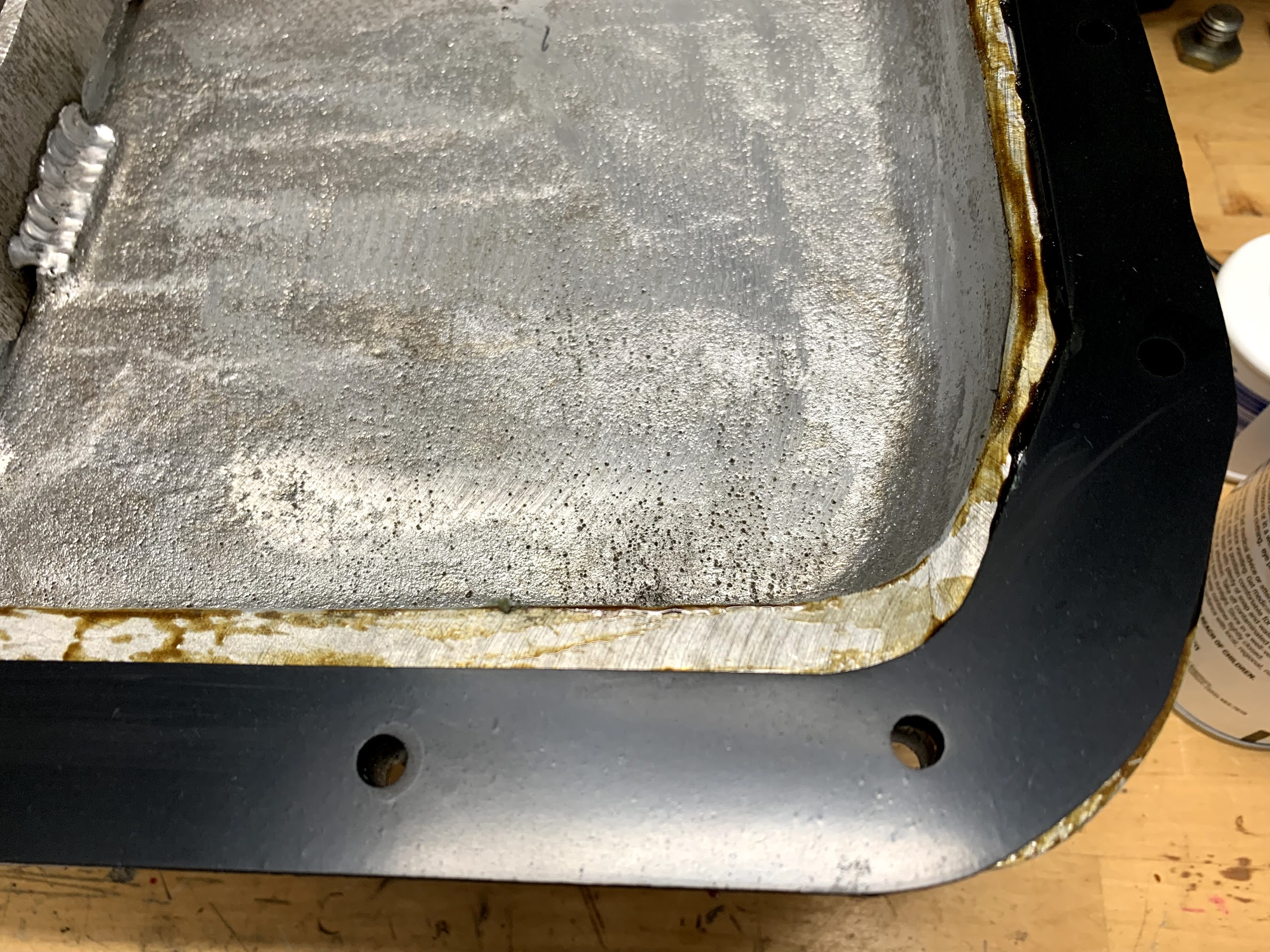
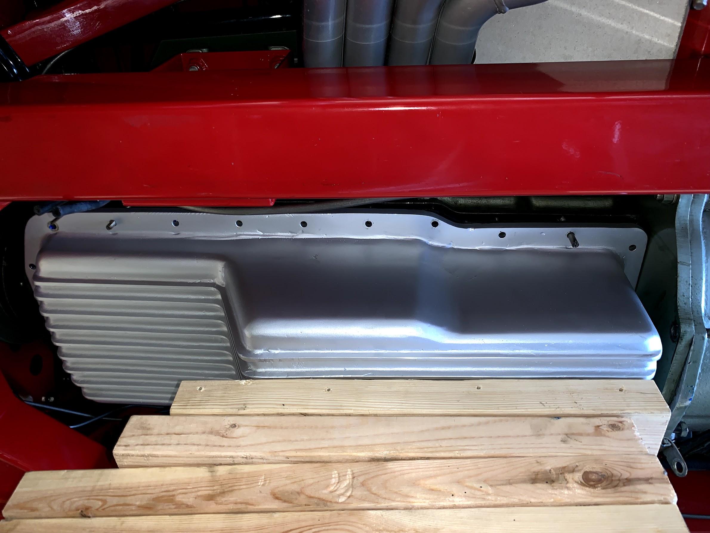
  • Replaced the oil sump gasket with a neoprene gasket from Tom’s Imports and ceramic coated the aluminum sump.
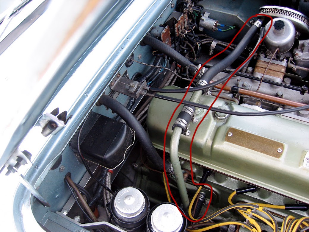
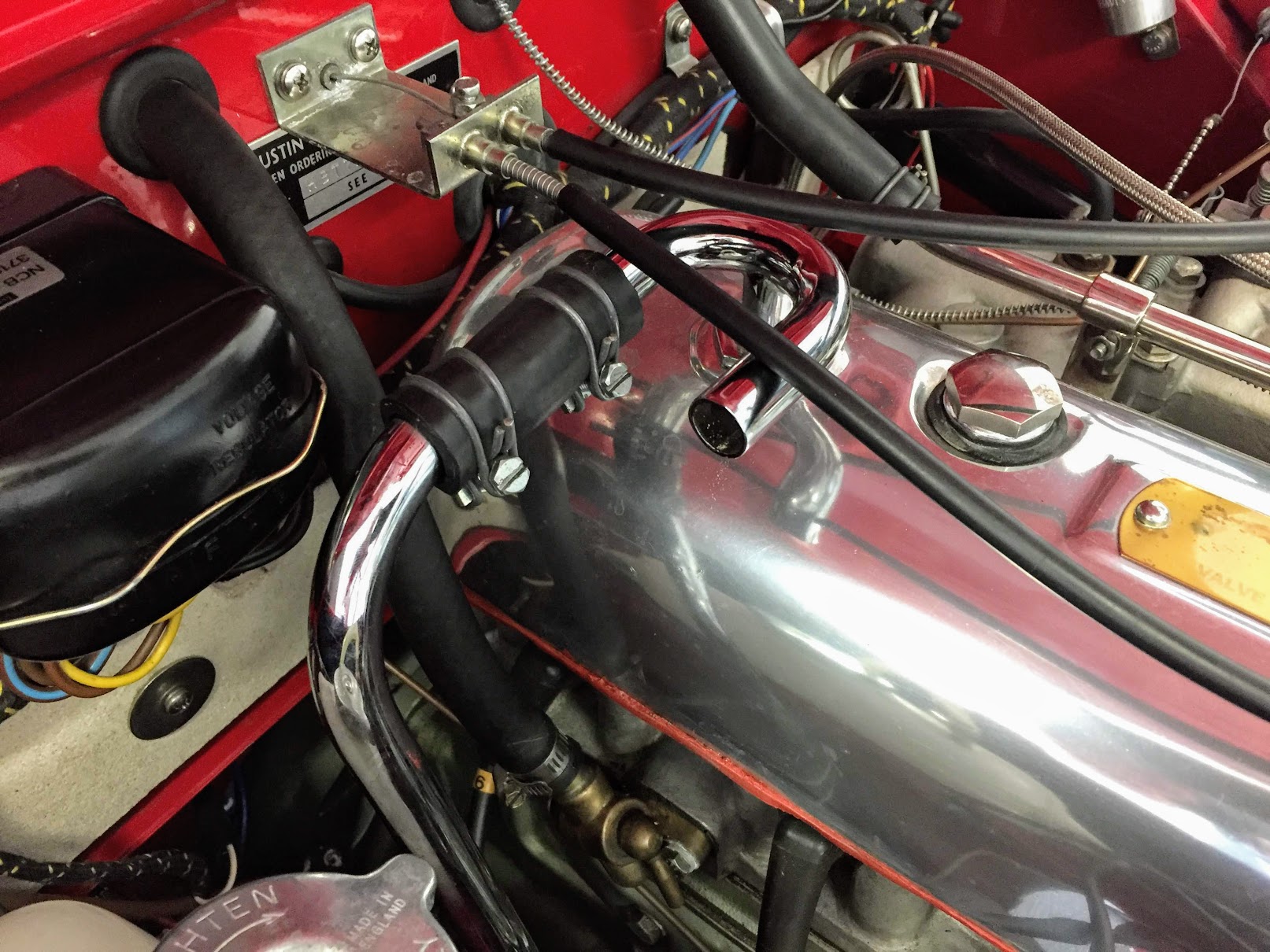
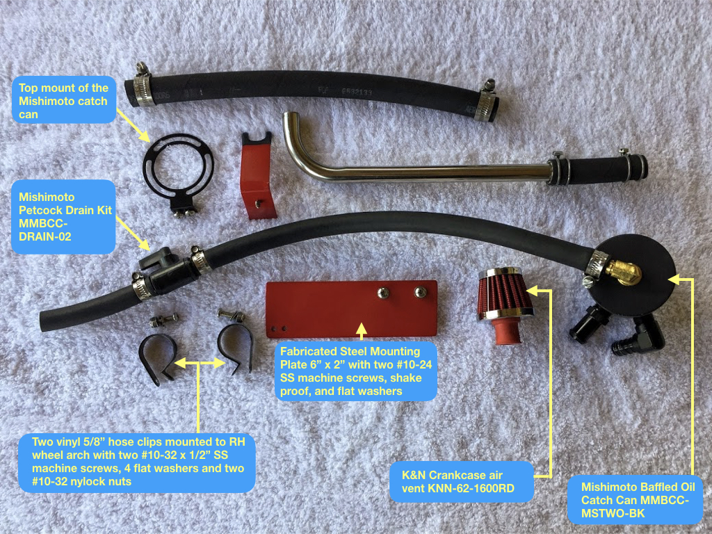
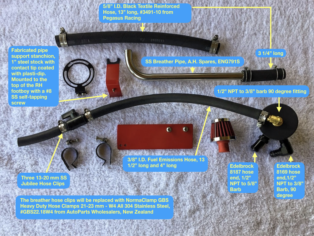
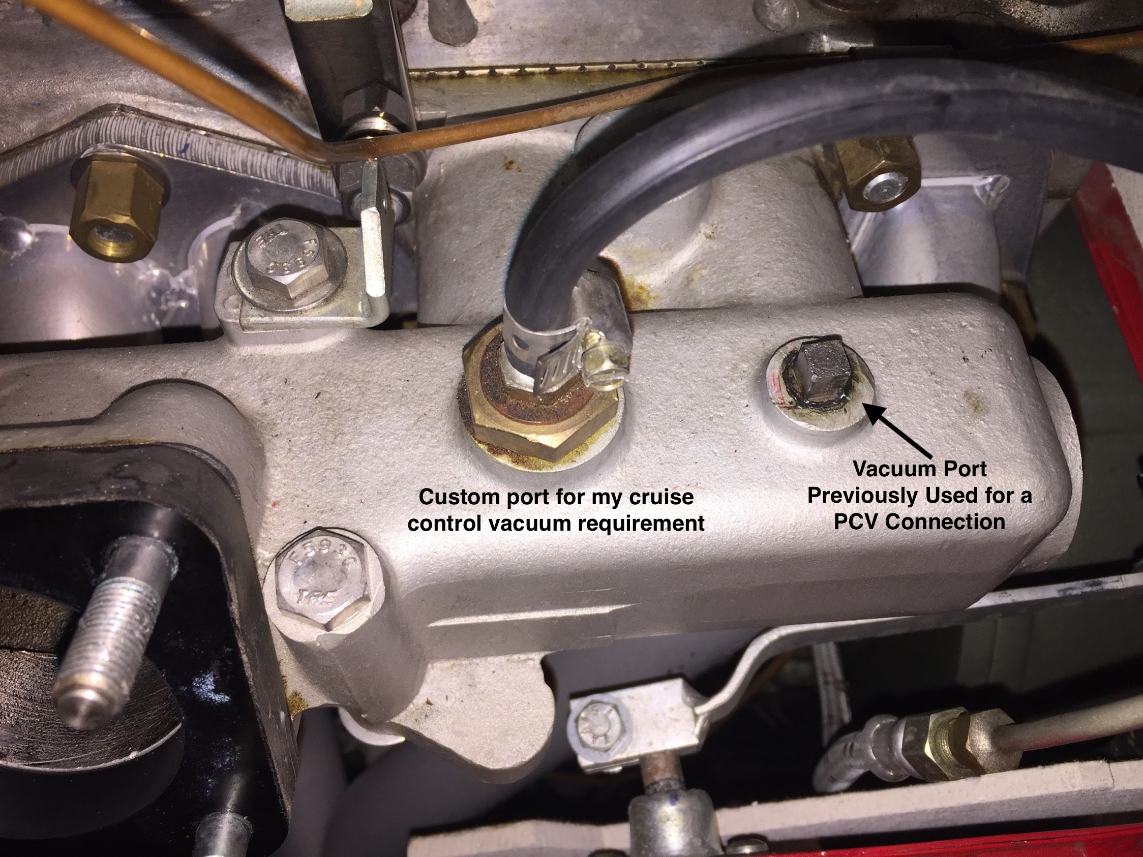
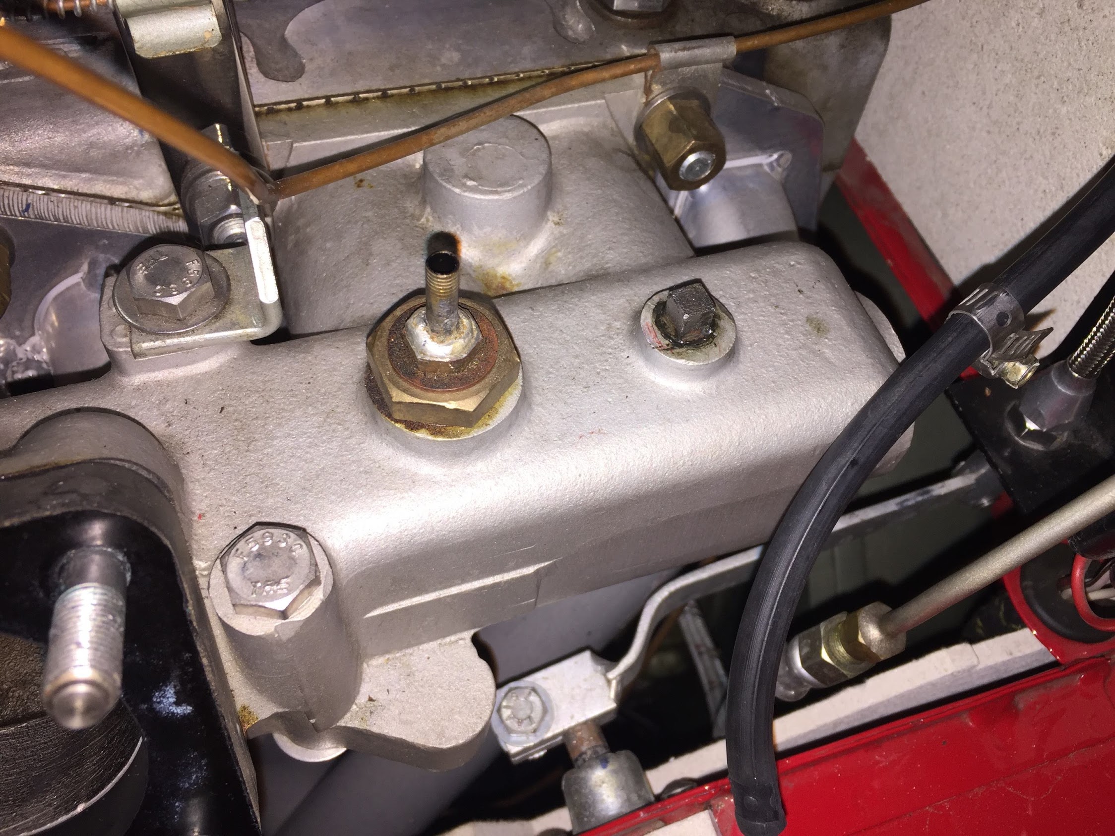
  • Removed the PCV system components and installed an oil catch can system.
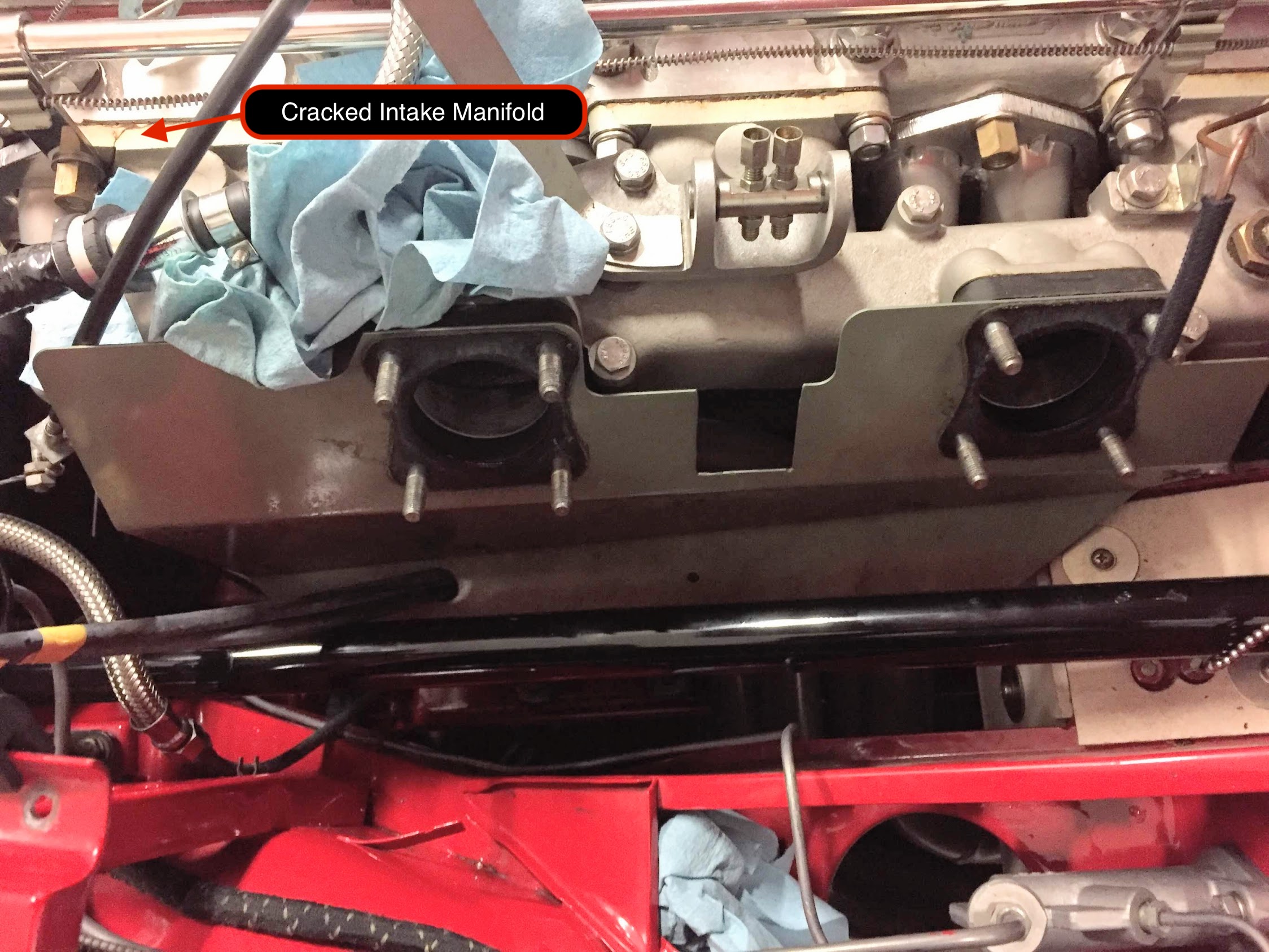
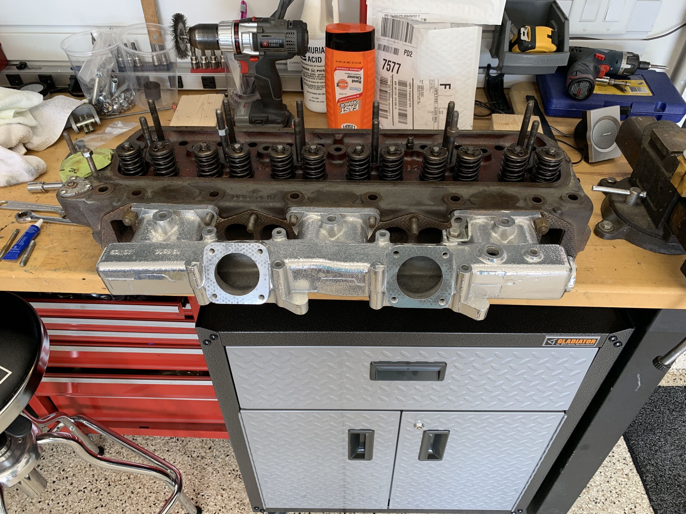
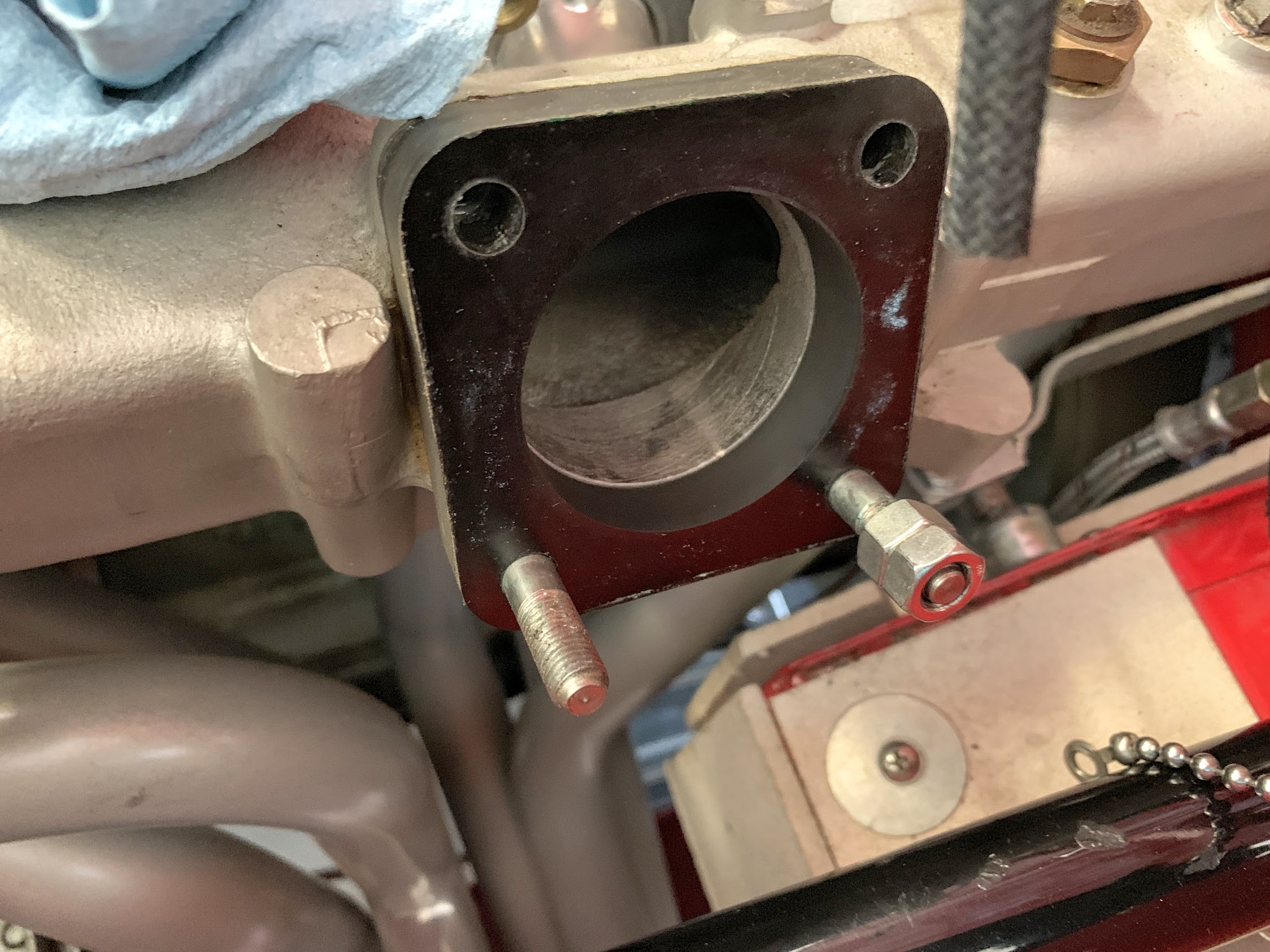
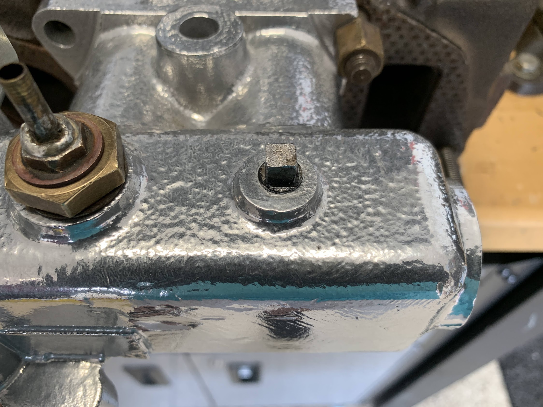
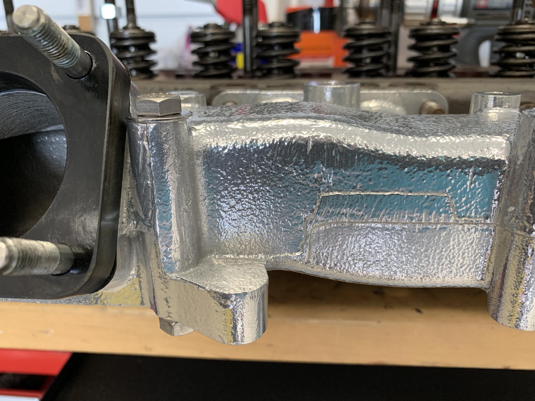
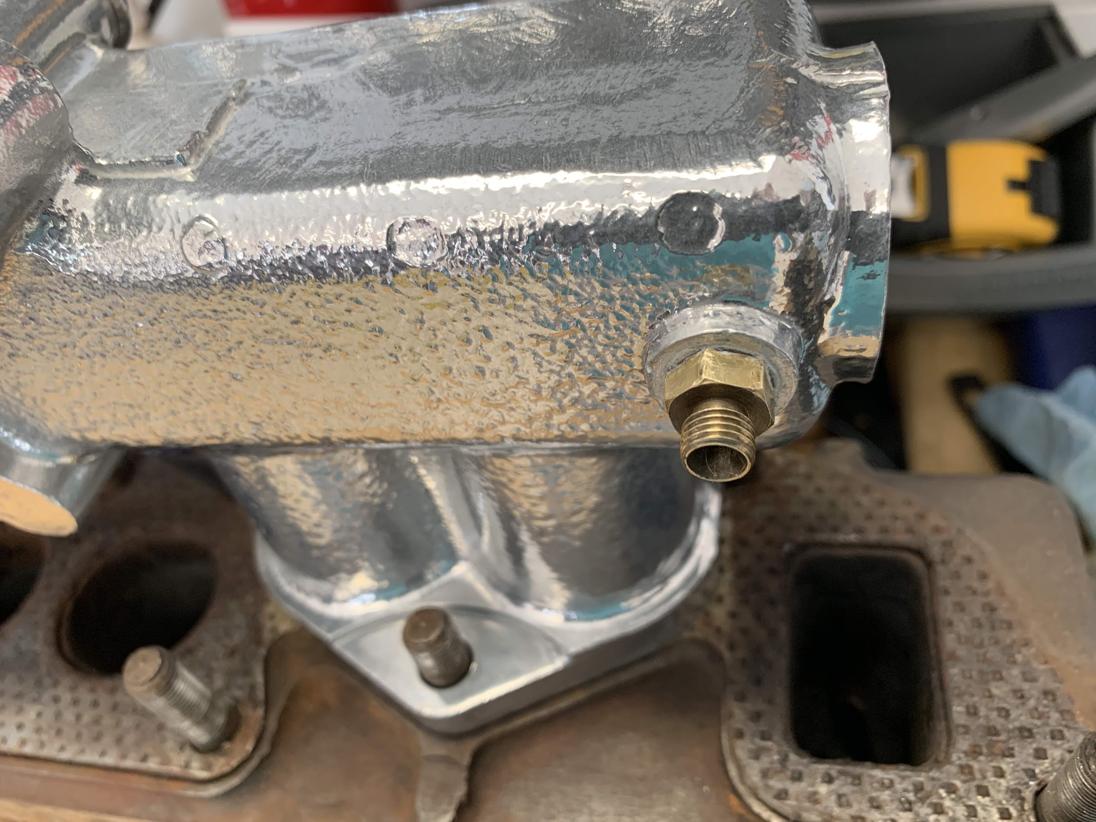
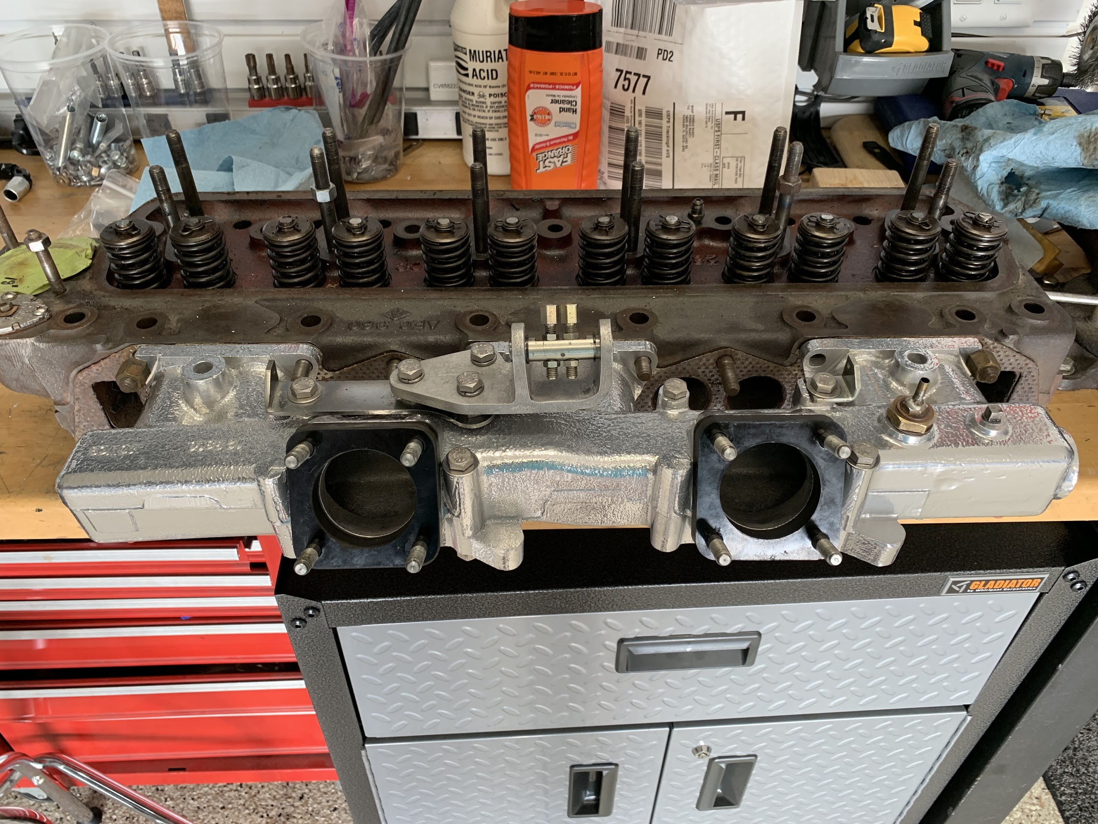
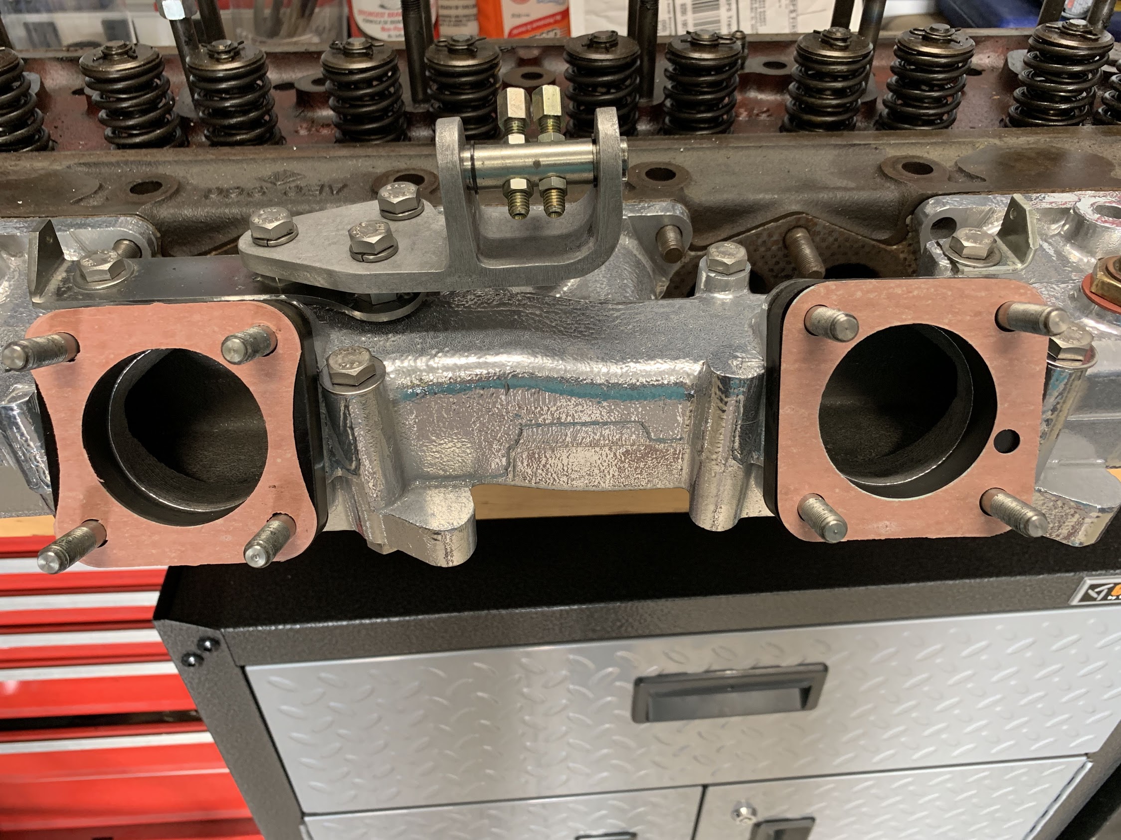
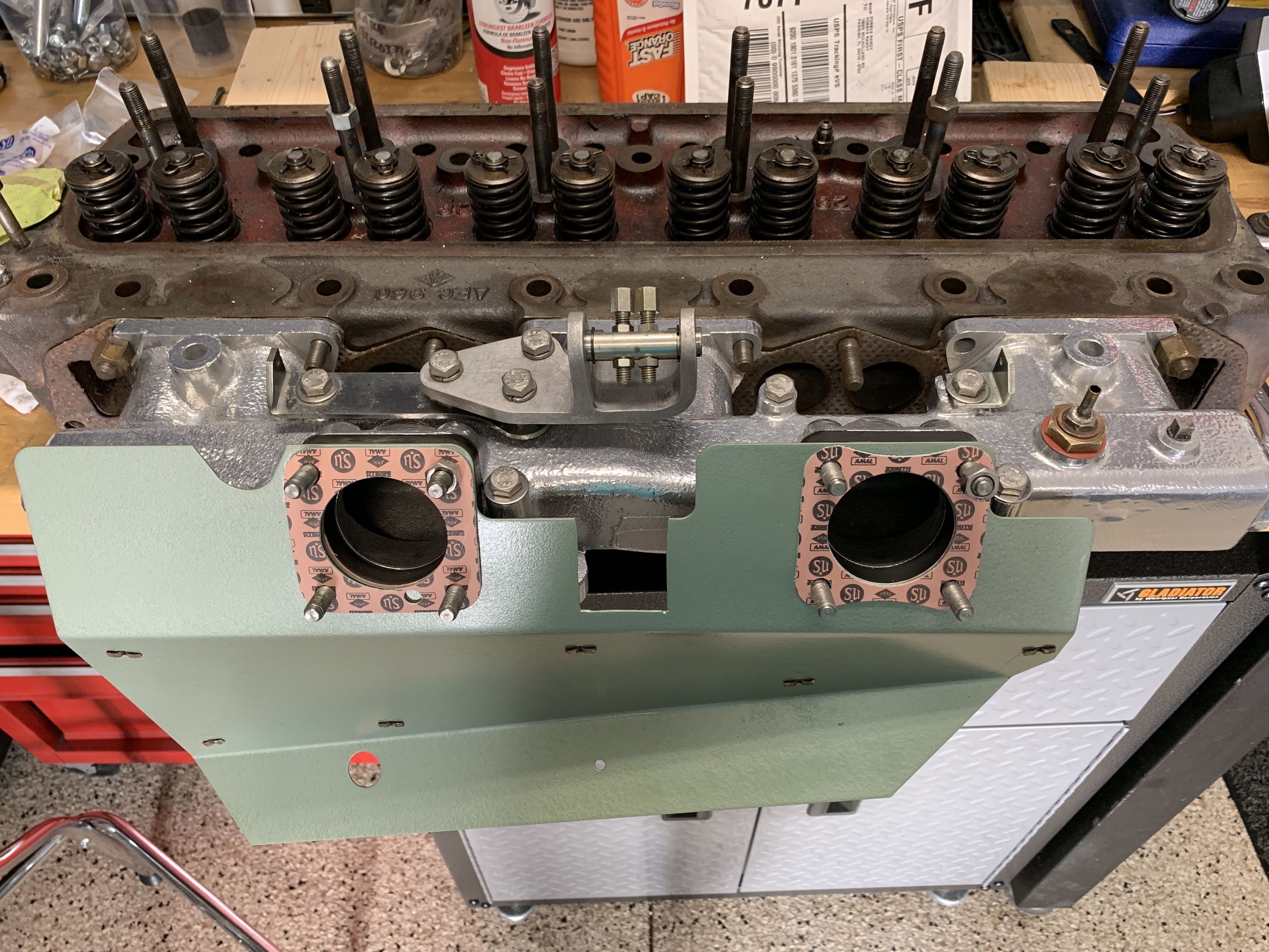
  • Replaced my intake manifold, which had two broken mounting ears due to improper installation, with another good, but used unit, sourced from Michael Salter. Jet-Hot coated the manifold before installation.
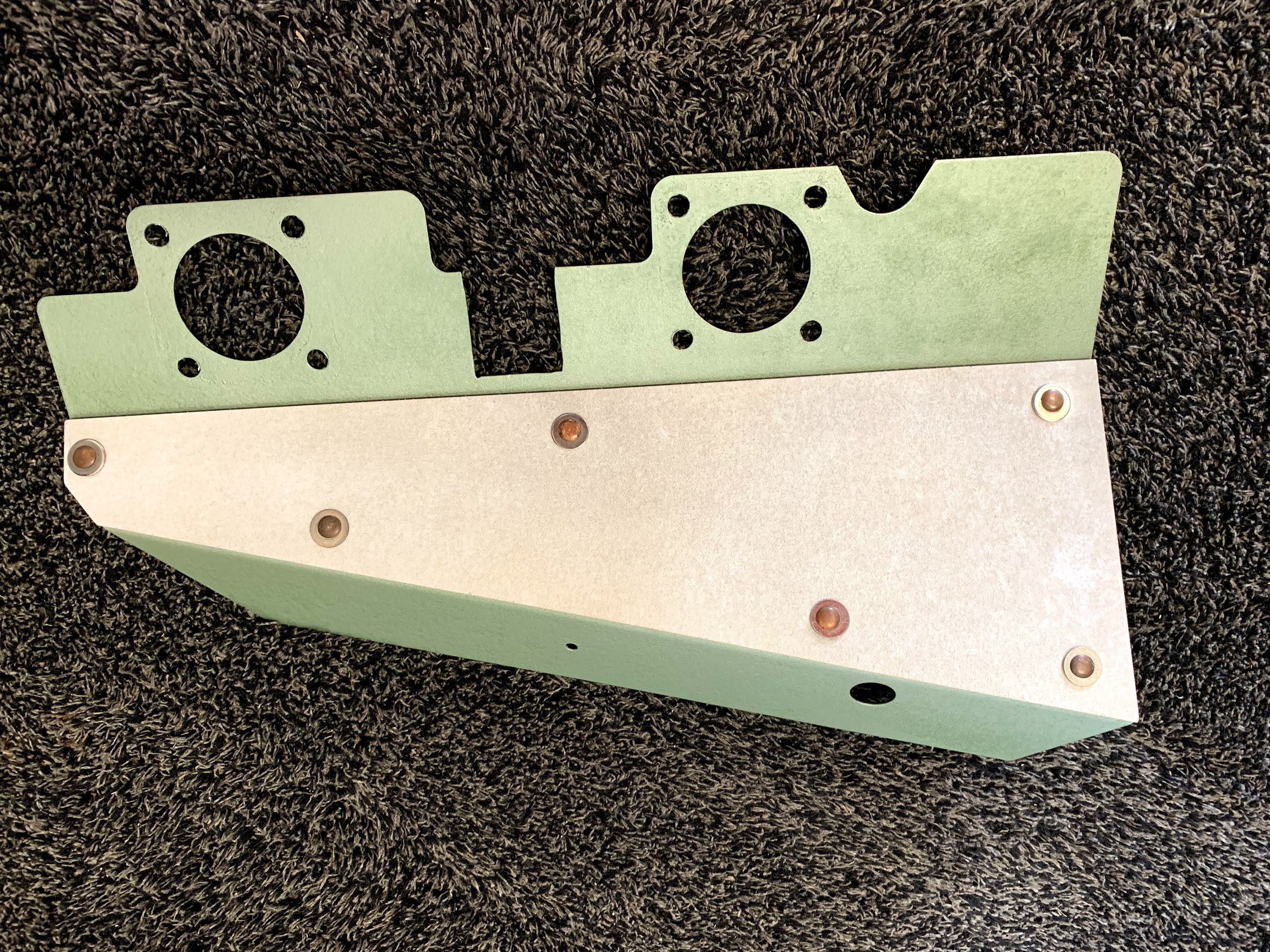
  • Cleaned and repainted the carburetor heat shield and refreshed the insulation.
  • Replaced the chromed “Austin-Healey” front shroud badge with a new component as the paint had chipped away on mine.
  • Replaced a leaking RH front Armstrong damper with a newly rebuilt unit from World Wide Auto Imports.
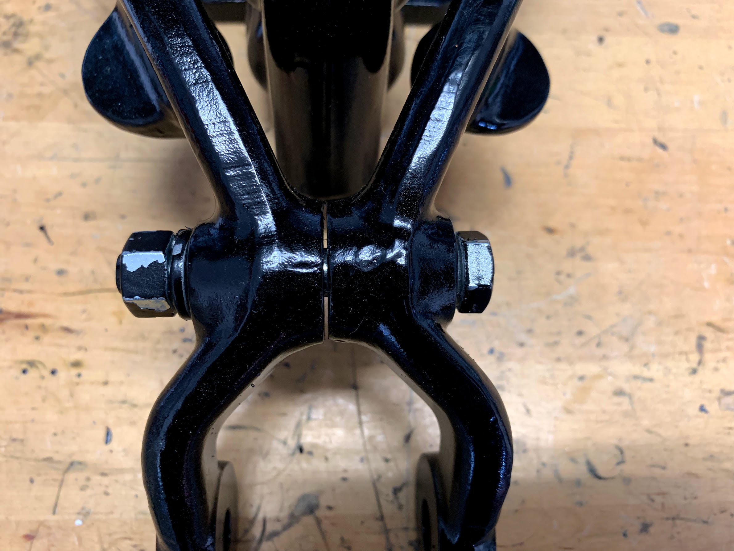
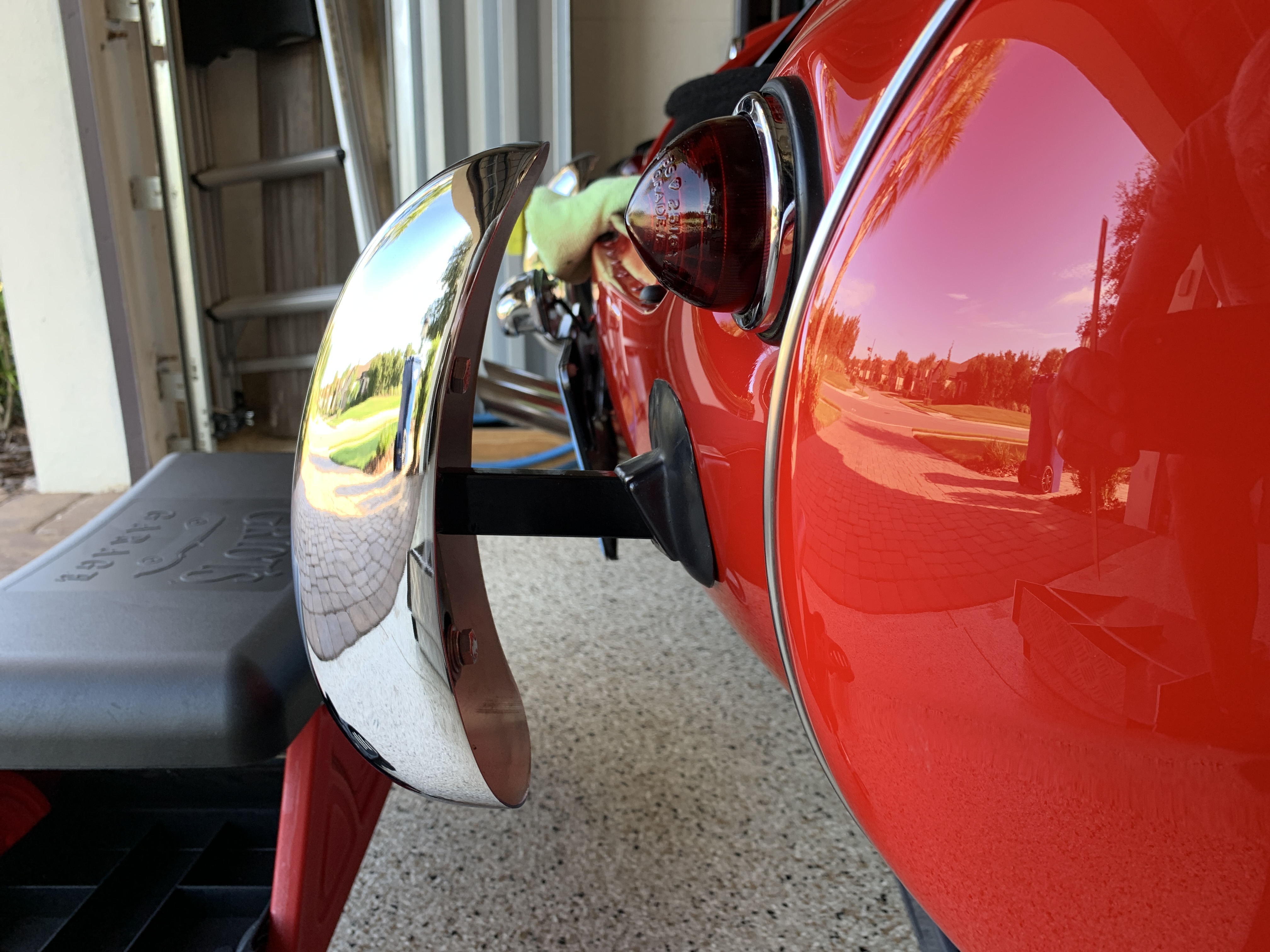
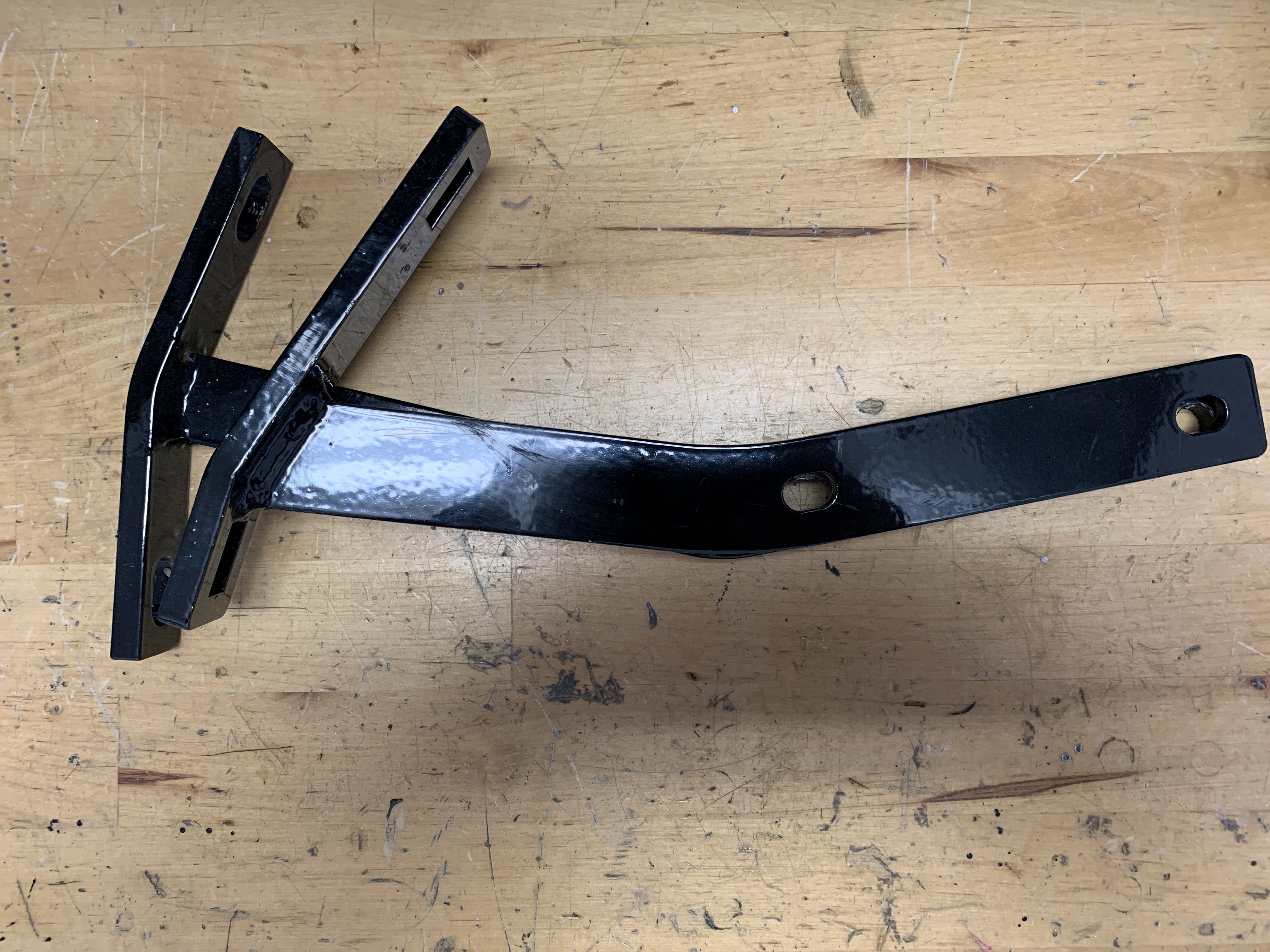
  • Replaced ill-fitting rear rally bumper irons with proper irons sourced from AH Spares. The first set had the bumperettes sitting too far from the rear shroud.
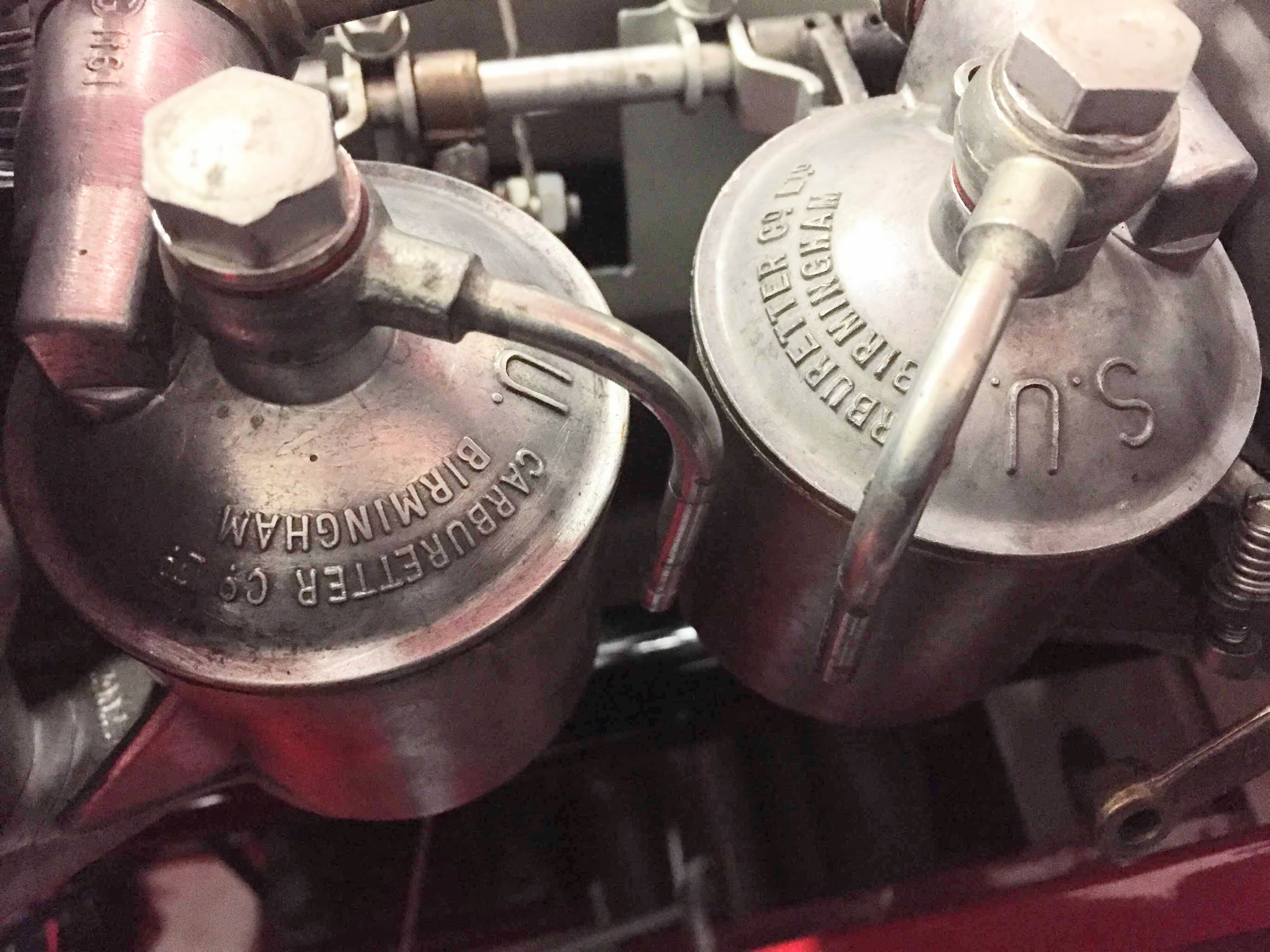
  • Had the HD8 SU carburetors rebuilt with delrin bushings installed by Thomas Bryant. Replaced both fuel bowl floats with nitrophyl floats. Added fuel bowl “Kouzies” from Joe Curto to insulate fuel bowls from exhaust heat and prevent vapor lock.
  • Sealed a persistent oil leak at the rear differential drain plug.
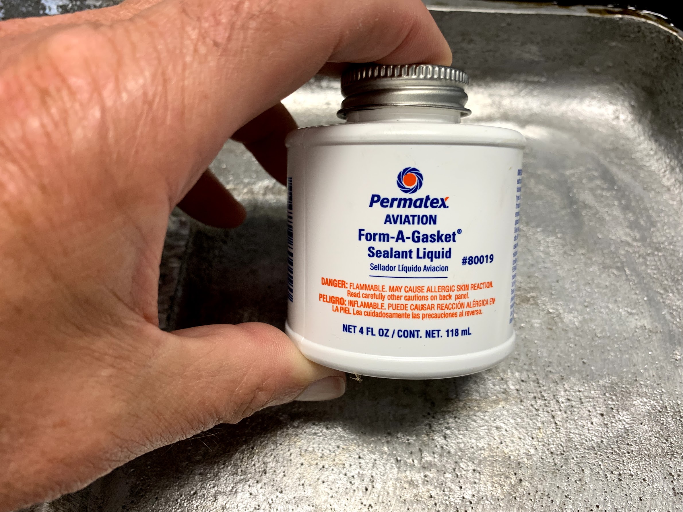
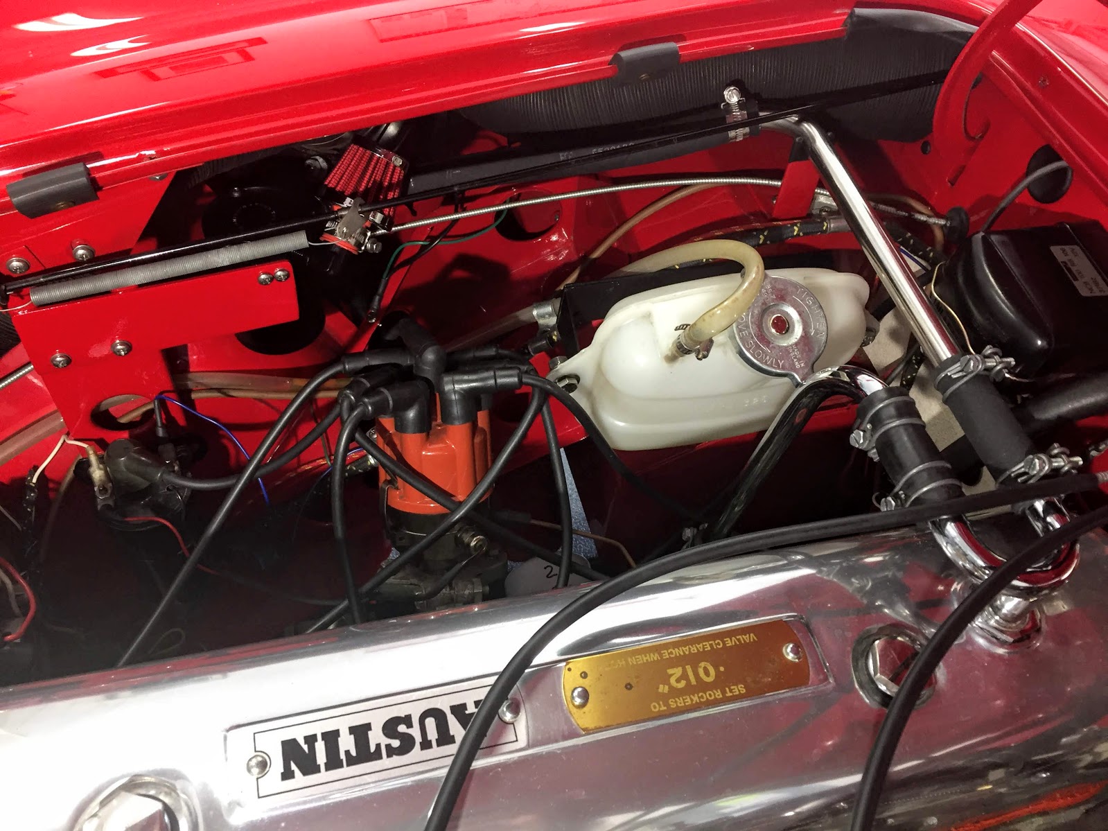
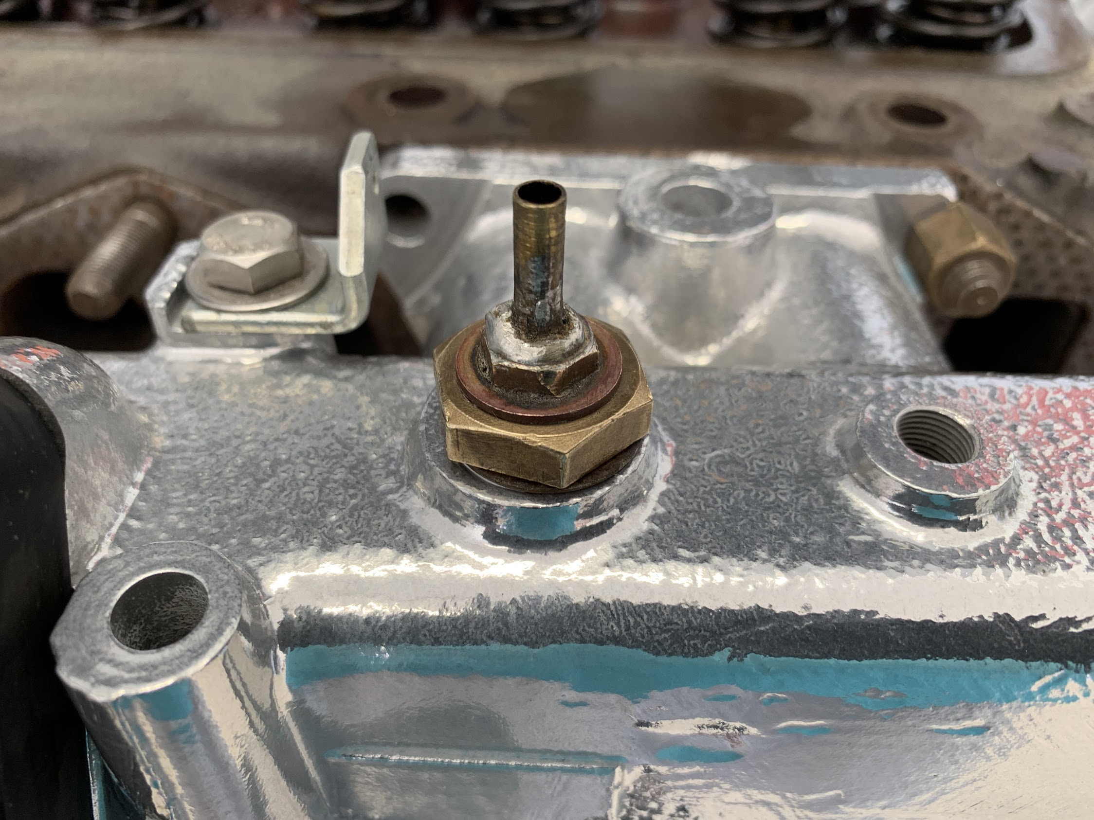
  • Adjusted valve clearances to spec. and sealed the cylinder head stud holes to prevent oil leaks.
  • Replaced the plastic (nylon?) breather fitting on the rear axle with a brass unit sold by Land Rover.
  • Replaced the clutch and brake master cylinders. Inspected the clutch slave cylinder and left it in place. Replace fluid and bled the system.
  • Installed a remote clutch slave cylinder bleeder hose from Ol Phartz Parts.
  • Replaced the original fuse panel with a seven fuse/fourteen terminal unit sourced from Charlie Hart.
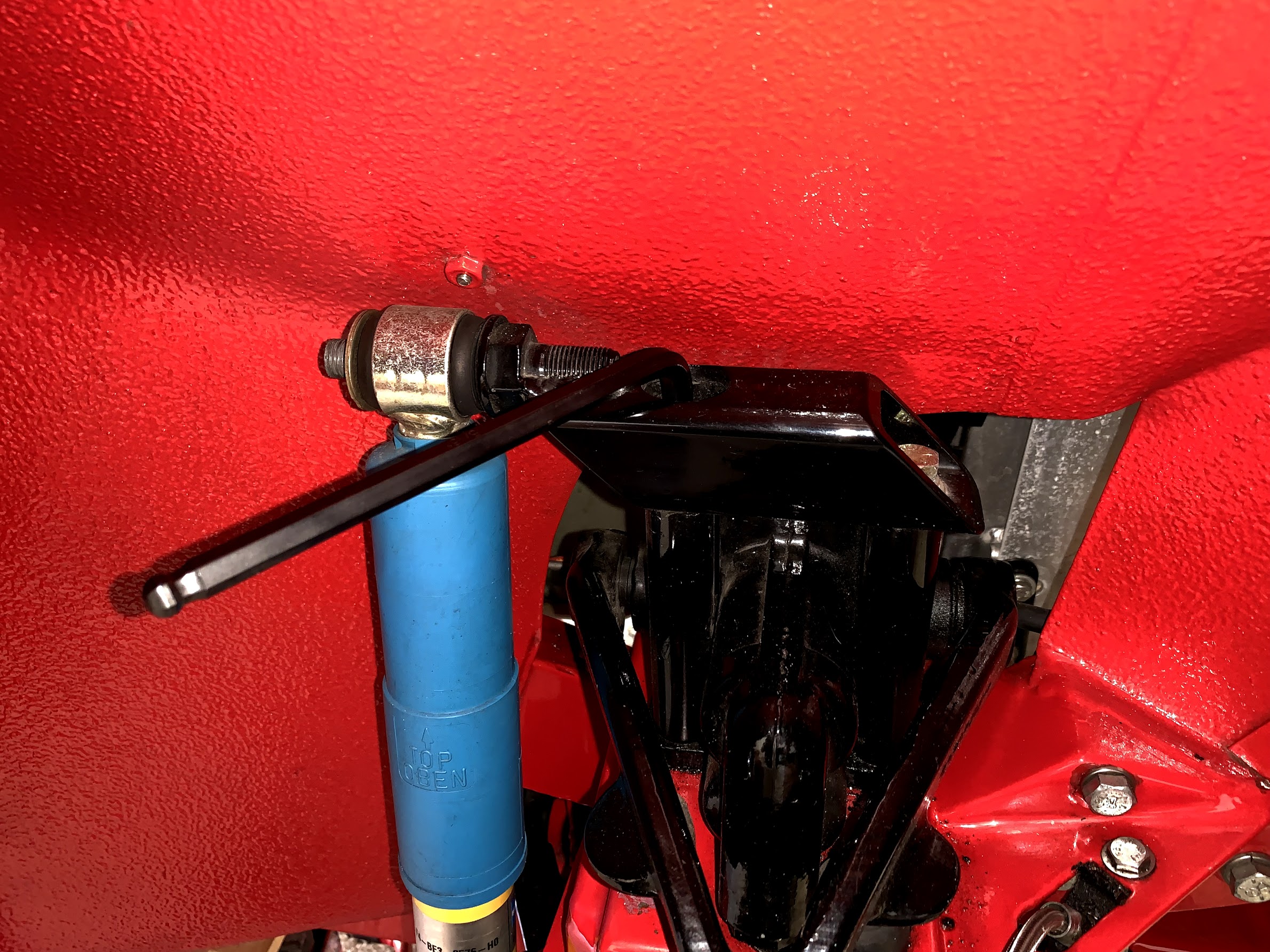
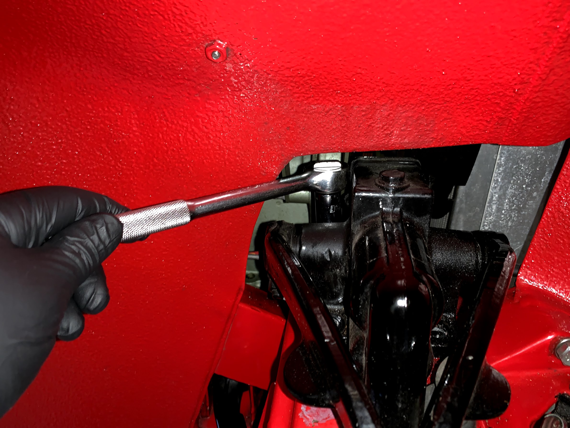
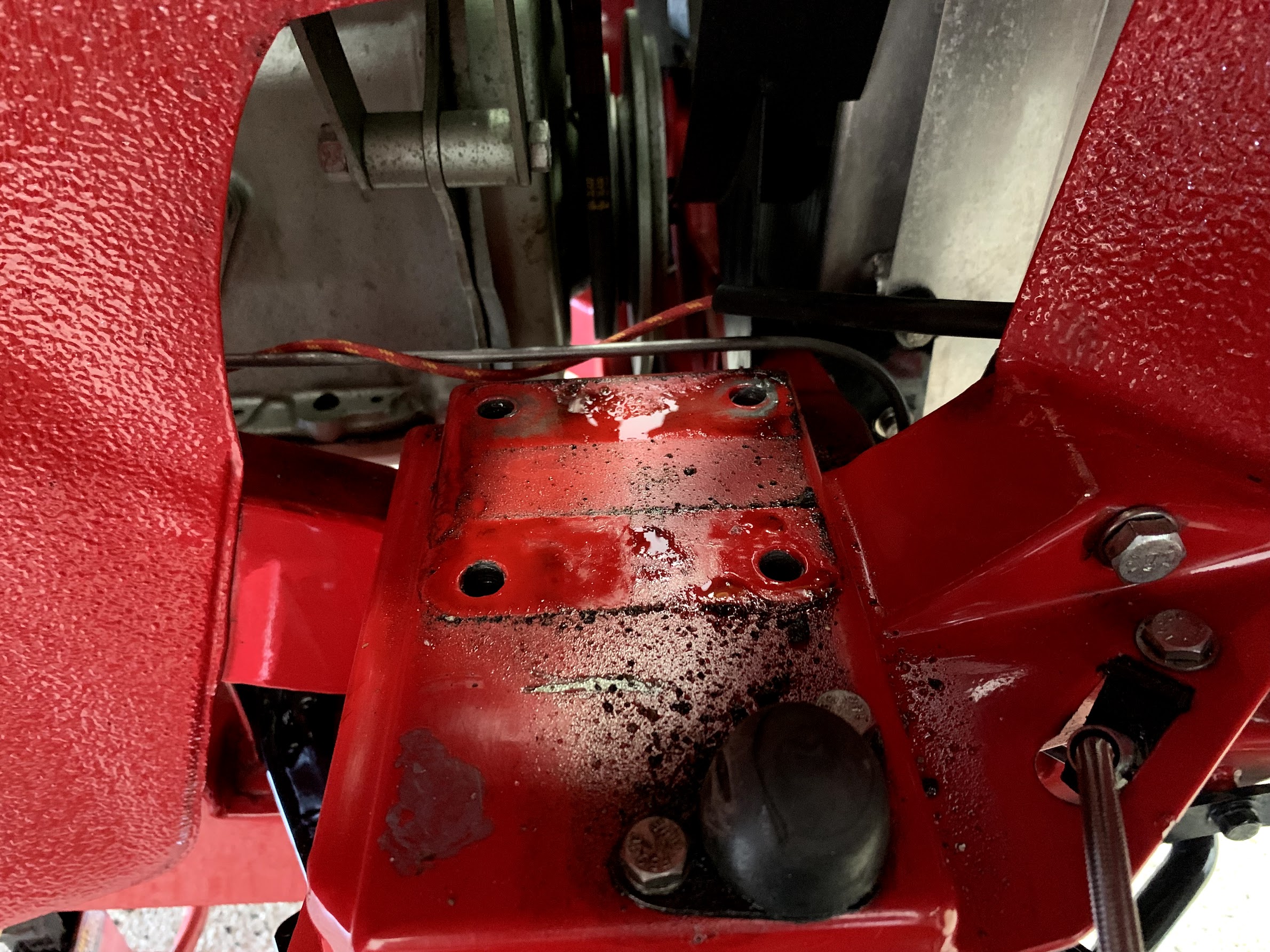
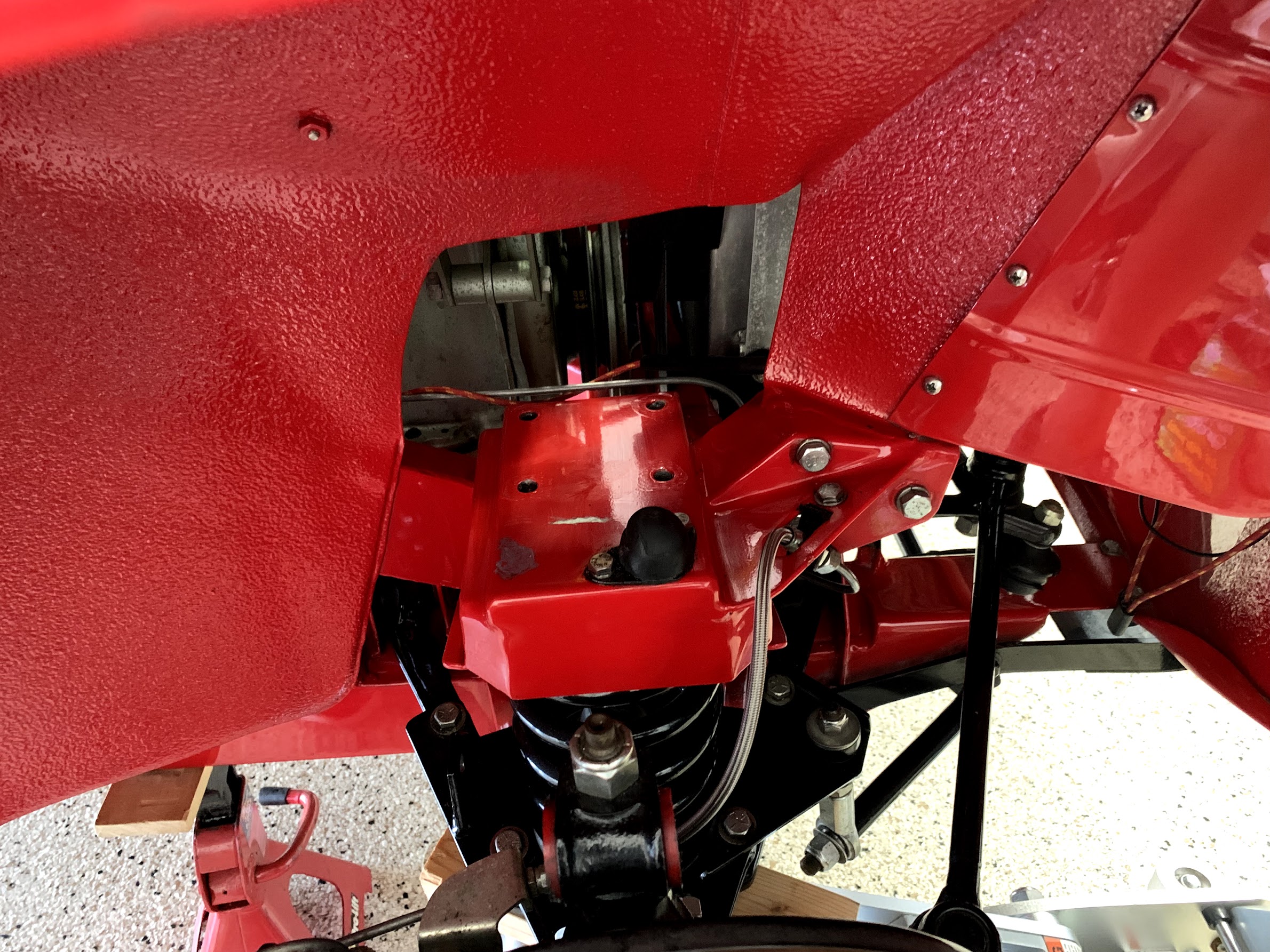
  • Fabricated and installed a rear main drip tray below the engine backplate/gearbox to catch oil leaks.
  • Replaced the front cylinder block cover gasket to eliminate an oil leak.
  • Replaced the alternator with a “new” rebuilt unit.
  • Replace the Halogen sealed beam headlights with aftermarket Lucas PL 700 headlights.
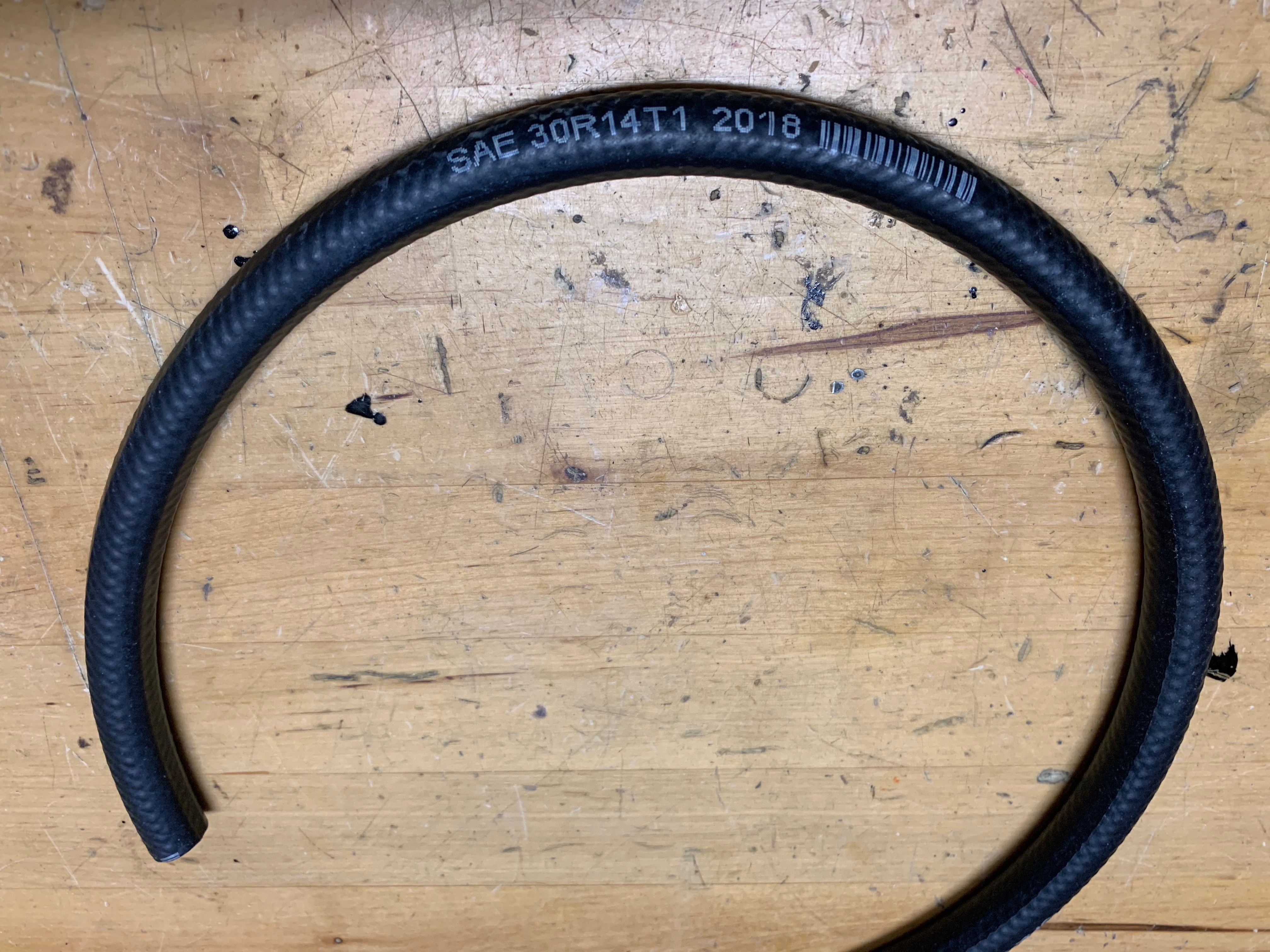
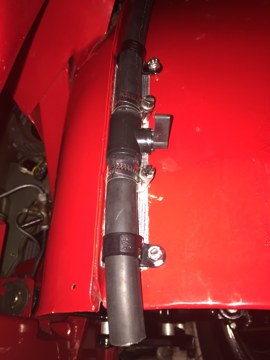
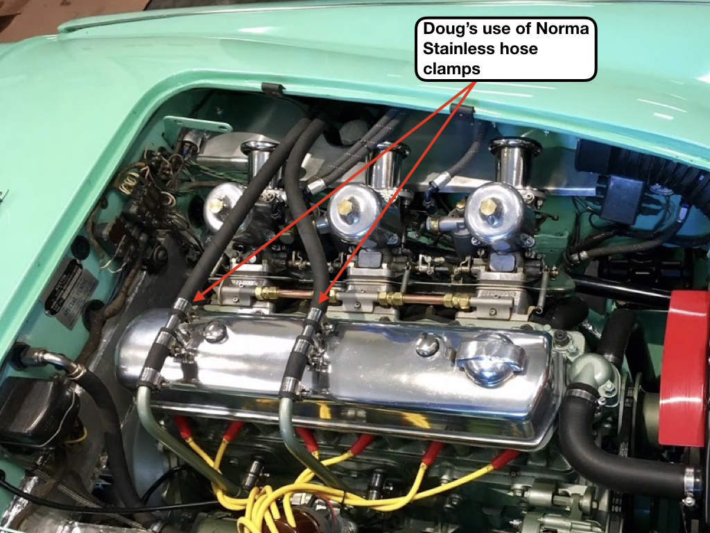
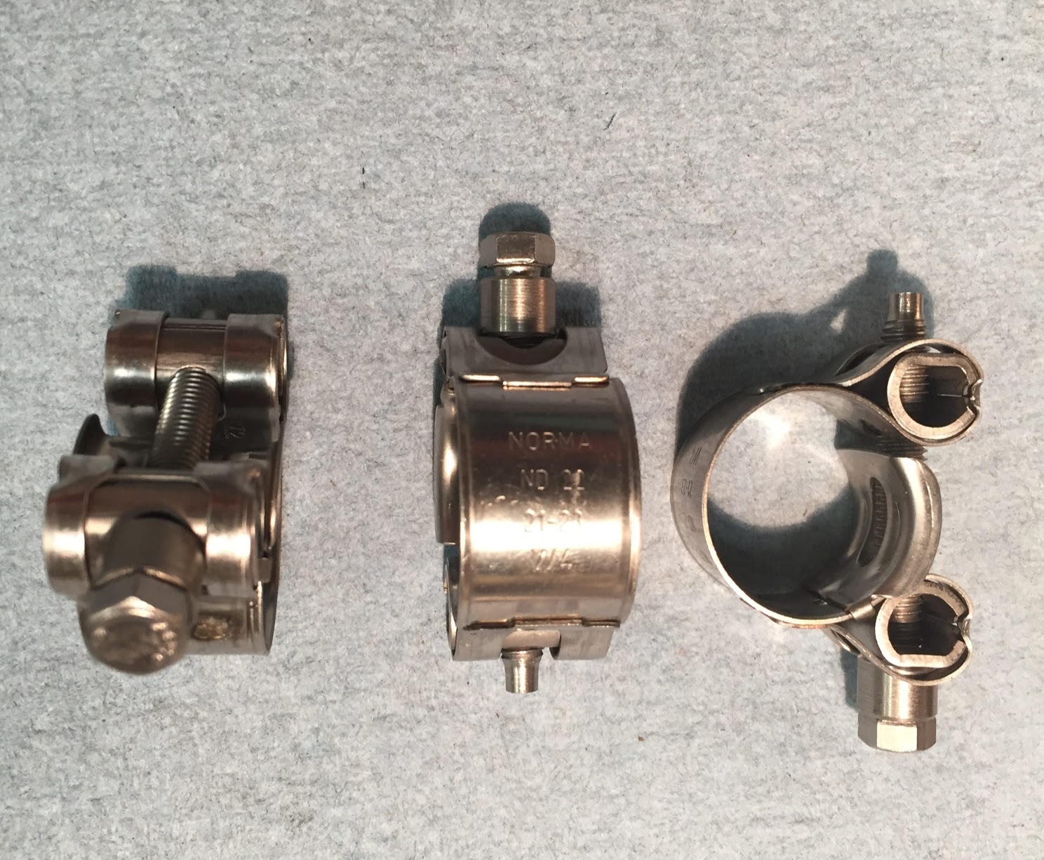
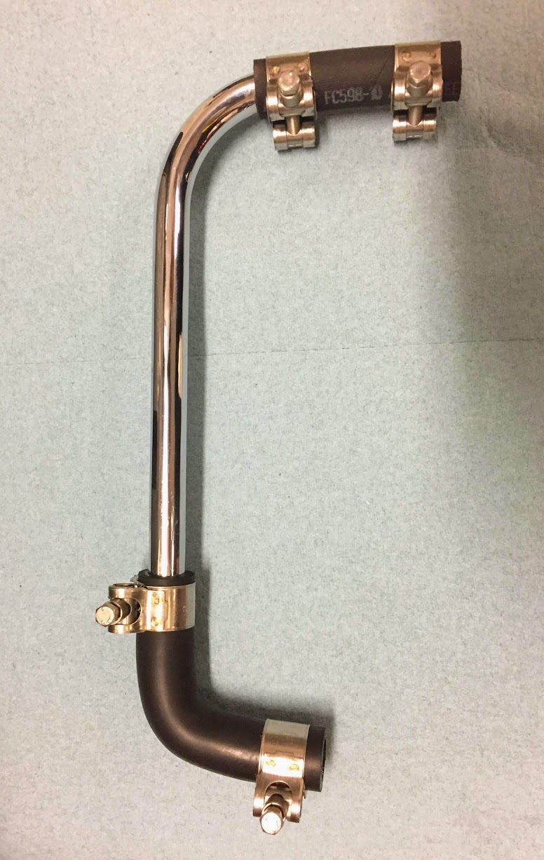
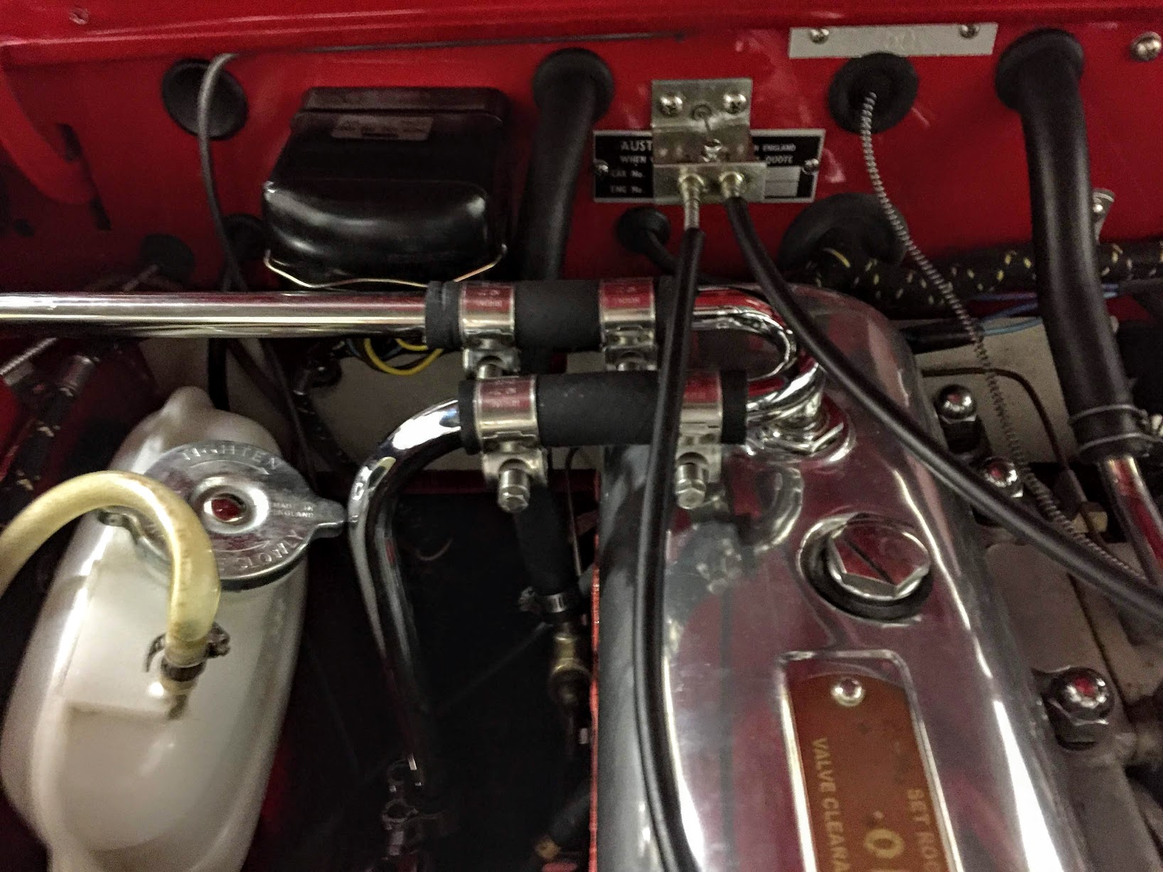
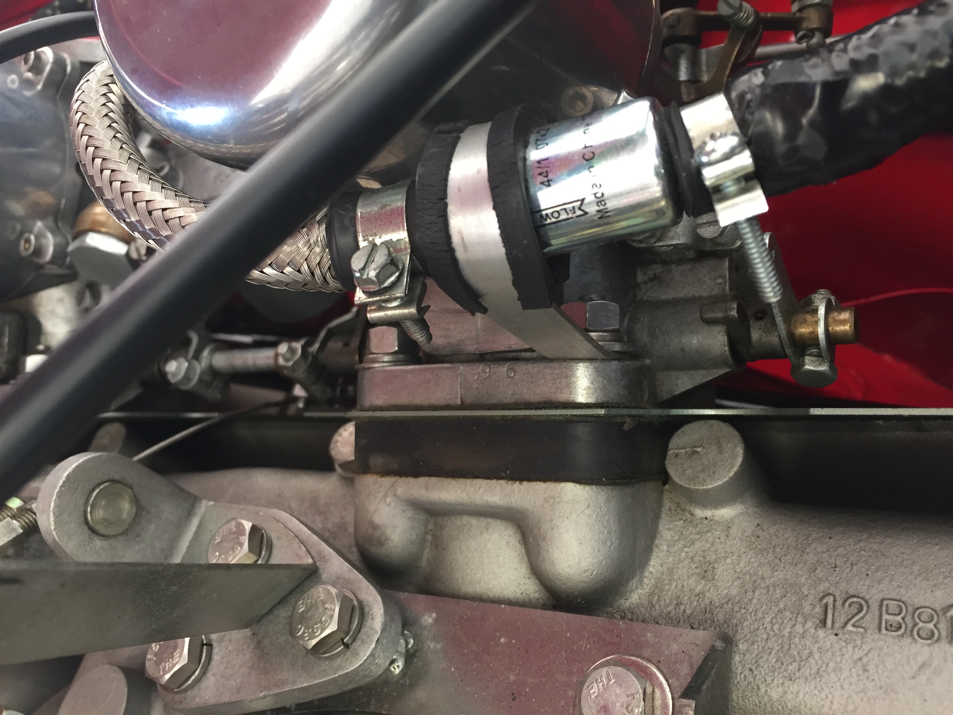
  • Replaced the original fuel hose delivery system from the hard fuel line to the carbs with a new design and fittings.
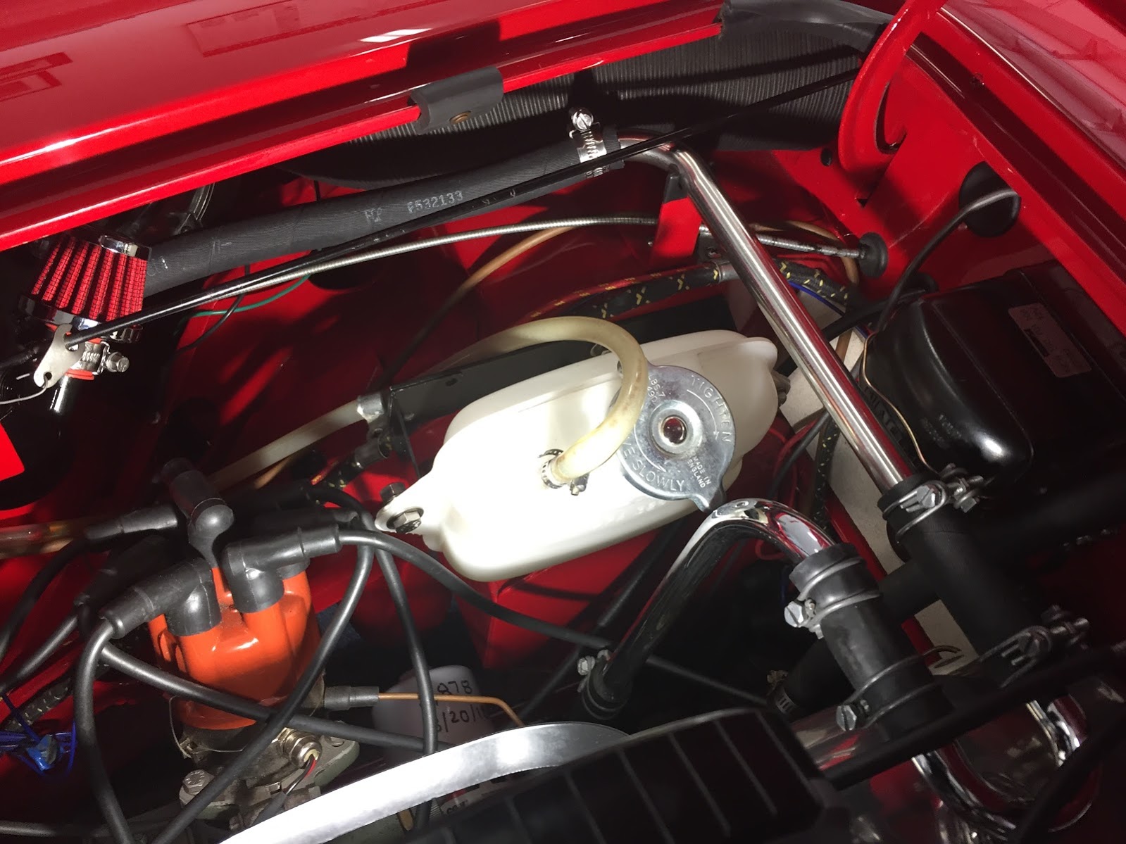
  • Added carburetor ram pipes and ITG air filtration socks.
  • Added an electric pusher fan in front of the radiator.
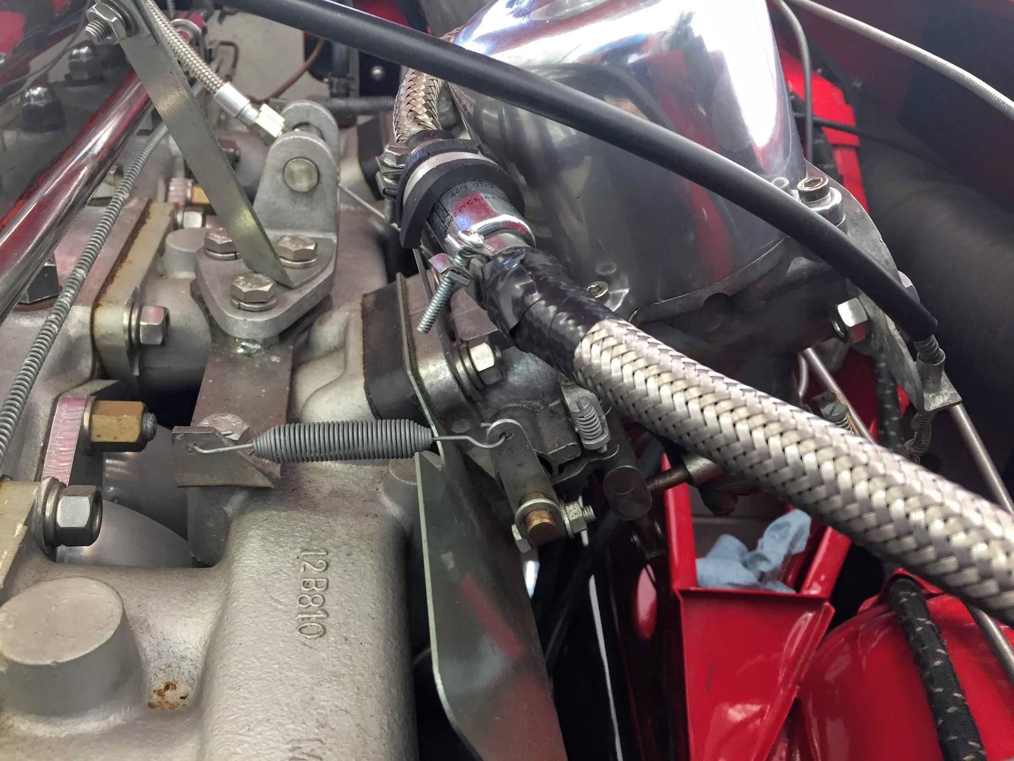
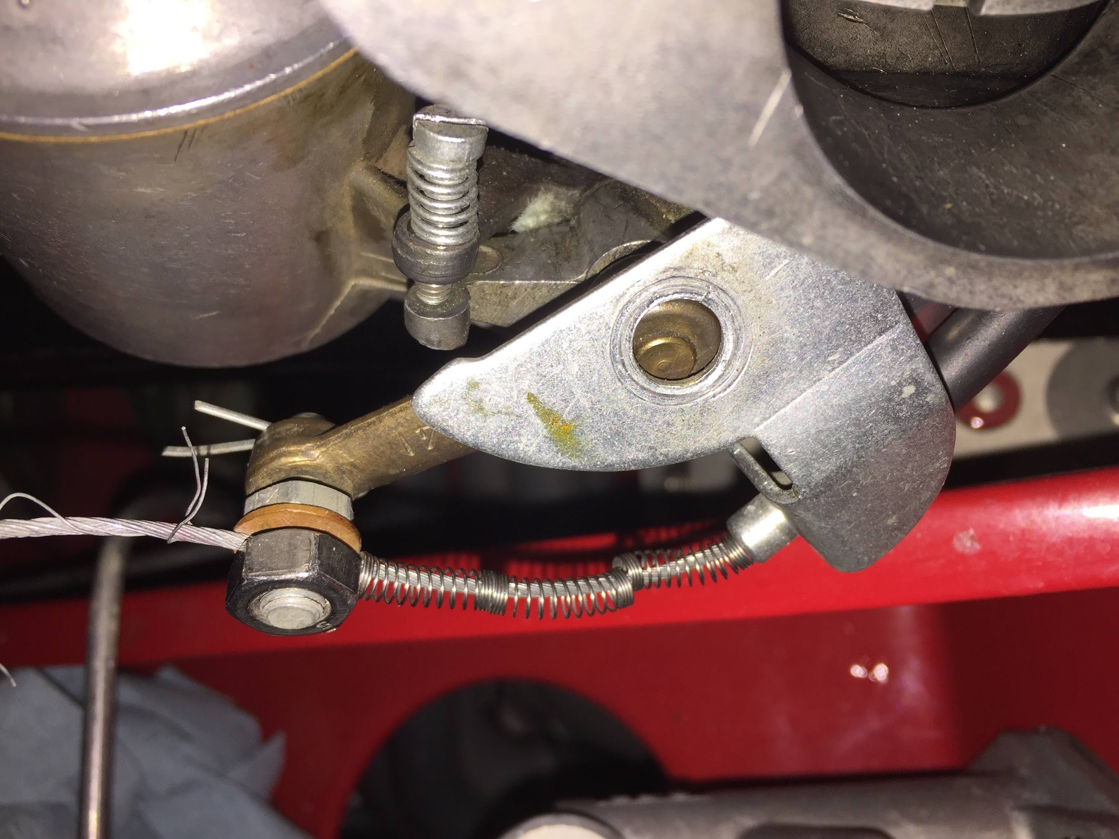
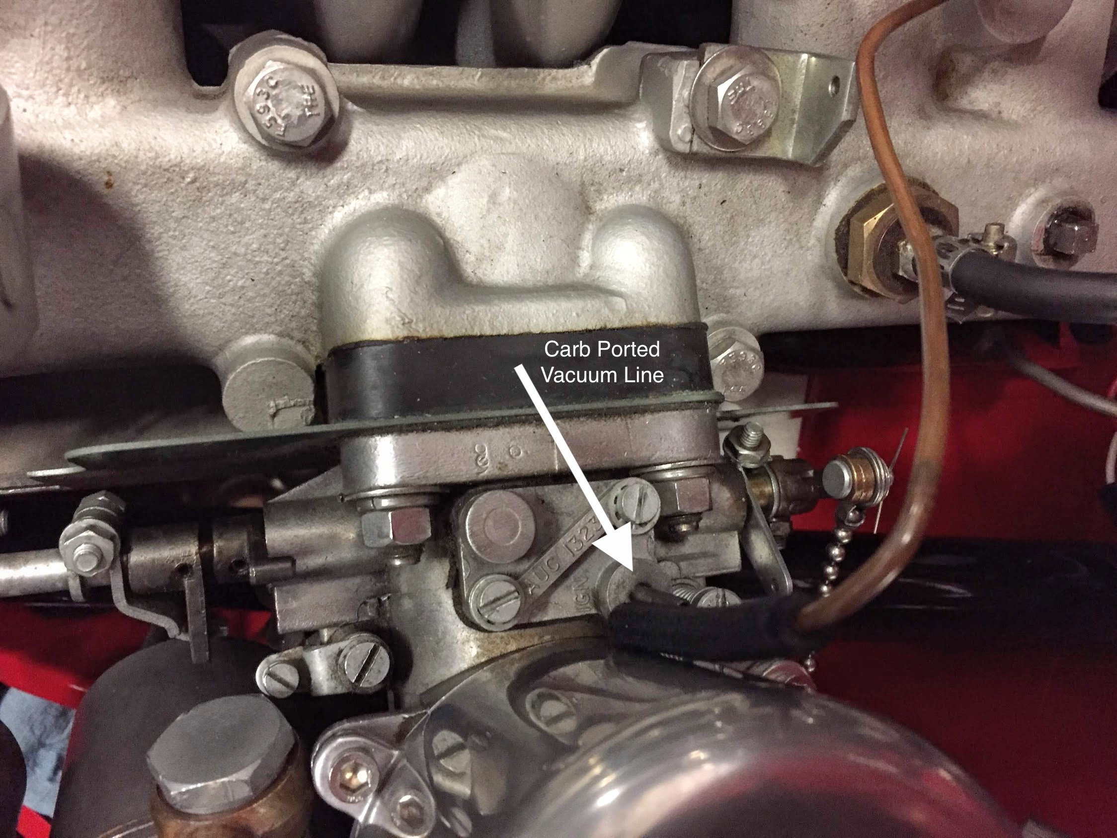
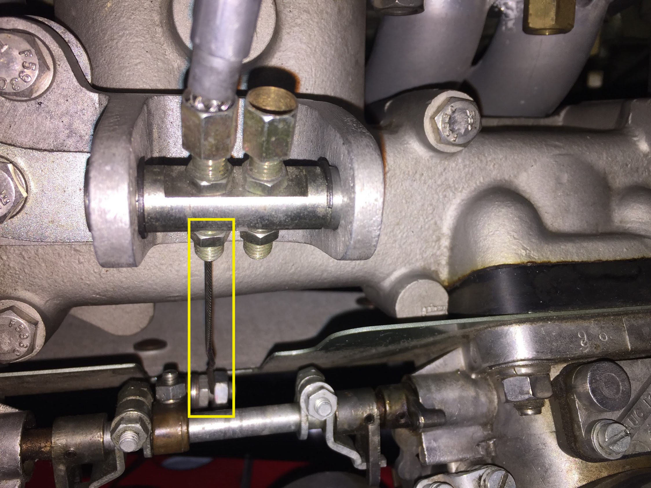
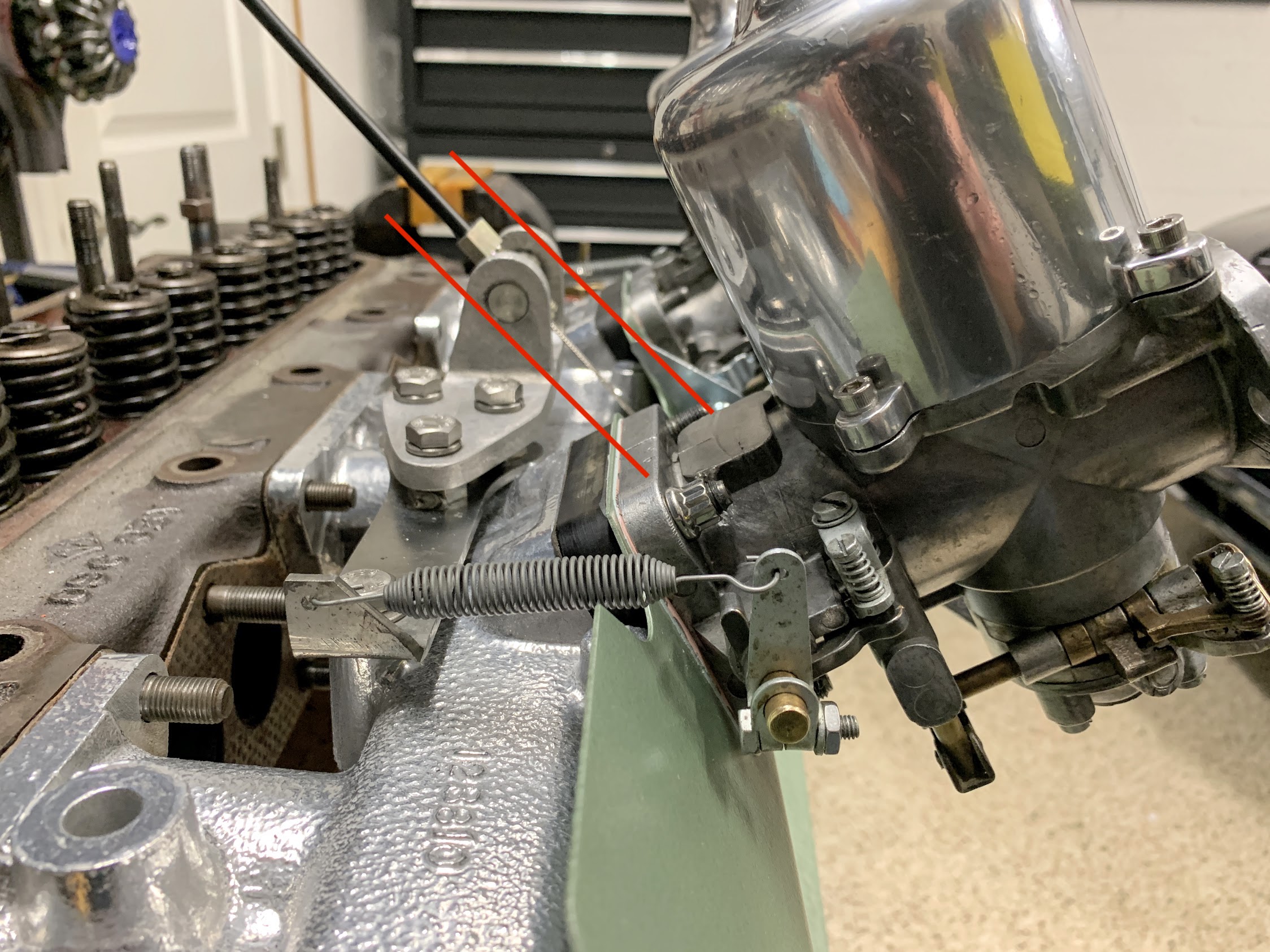
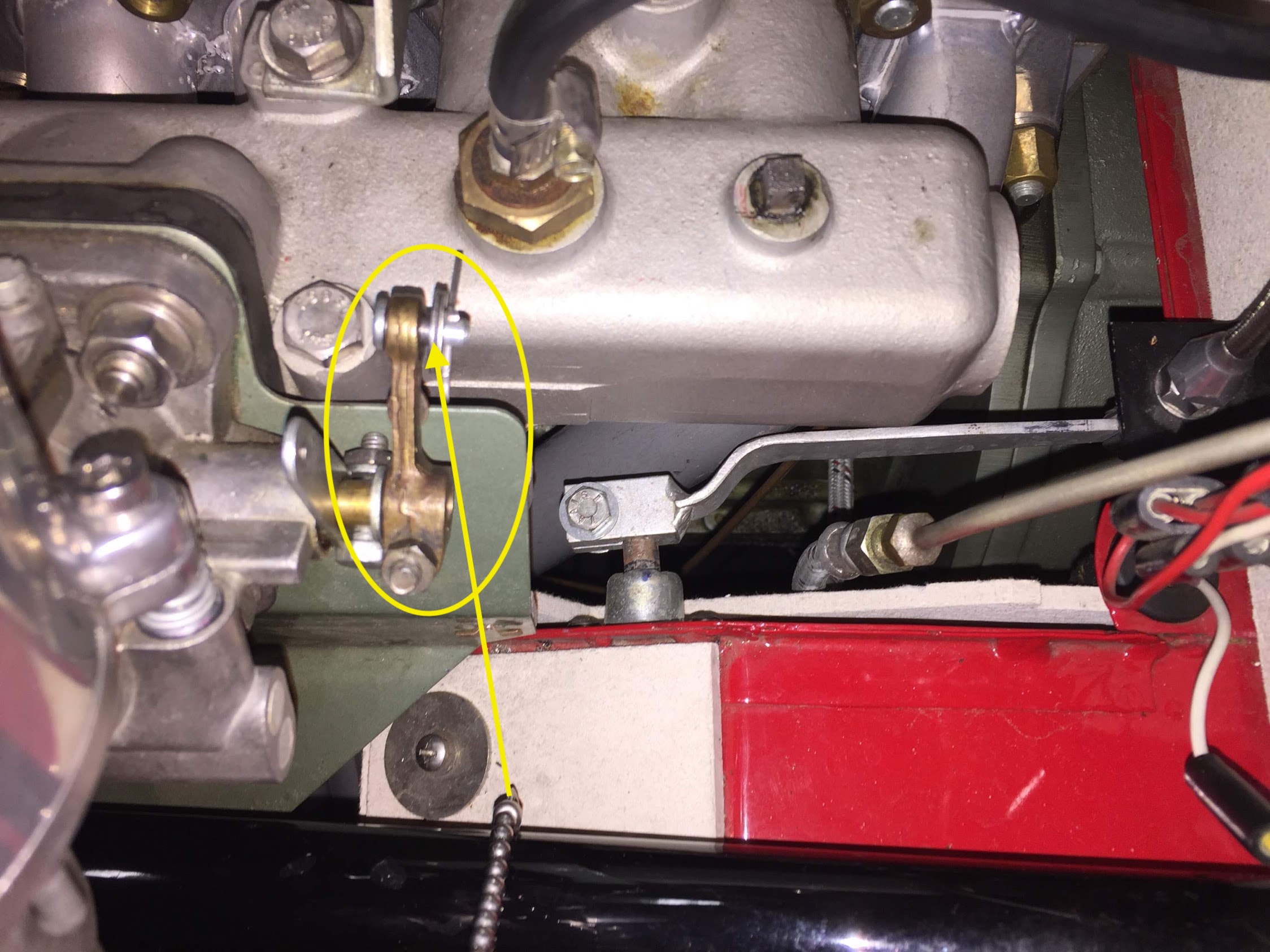
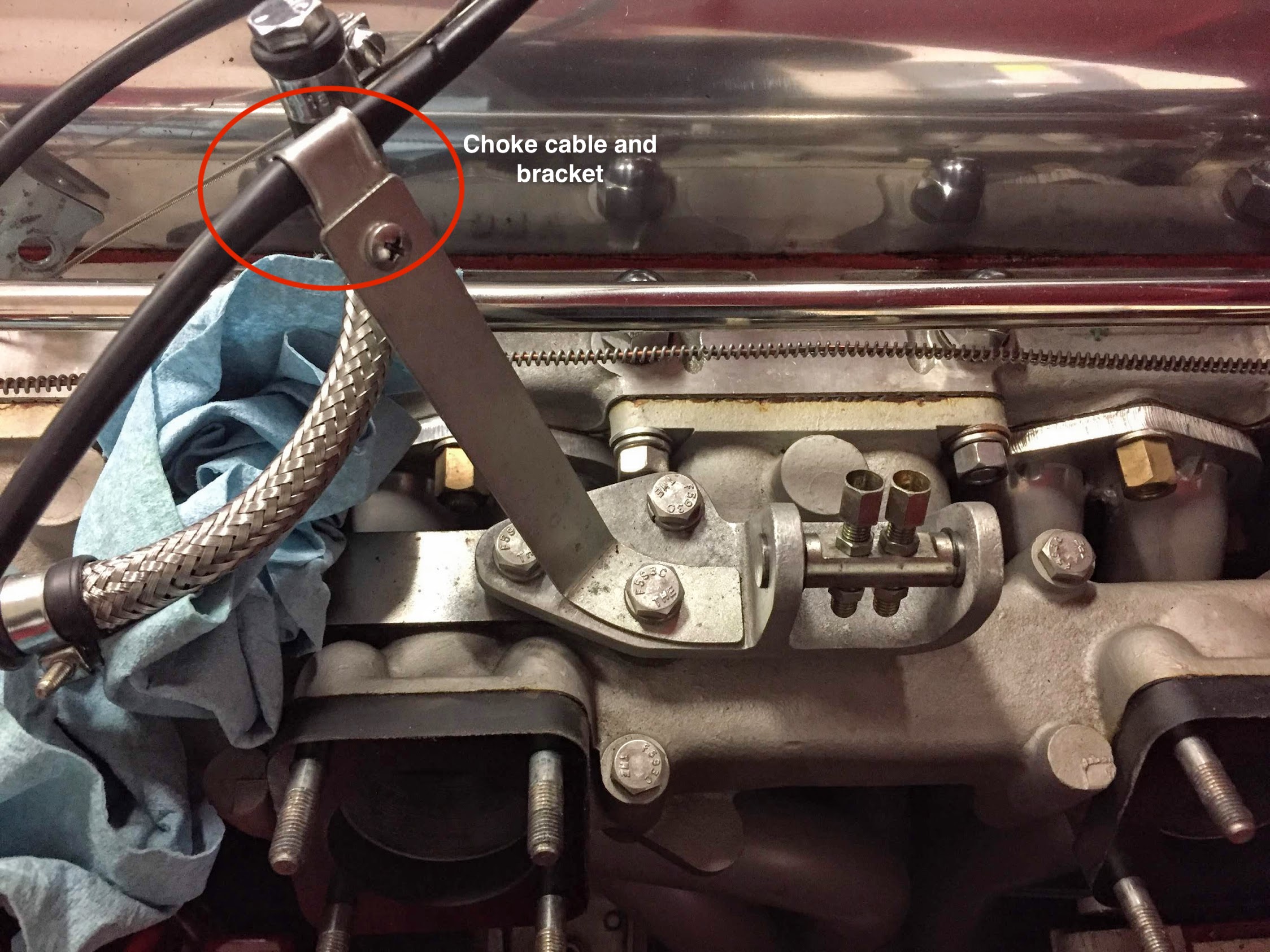
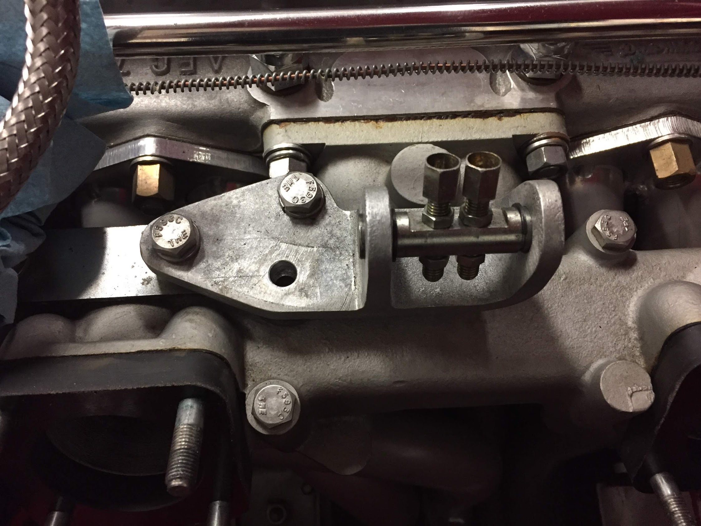
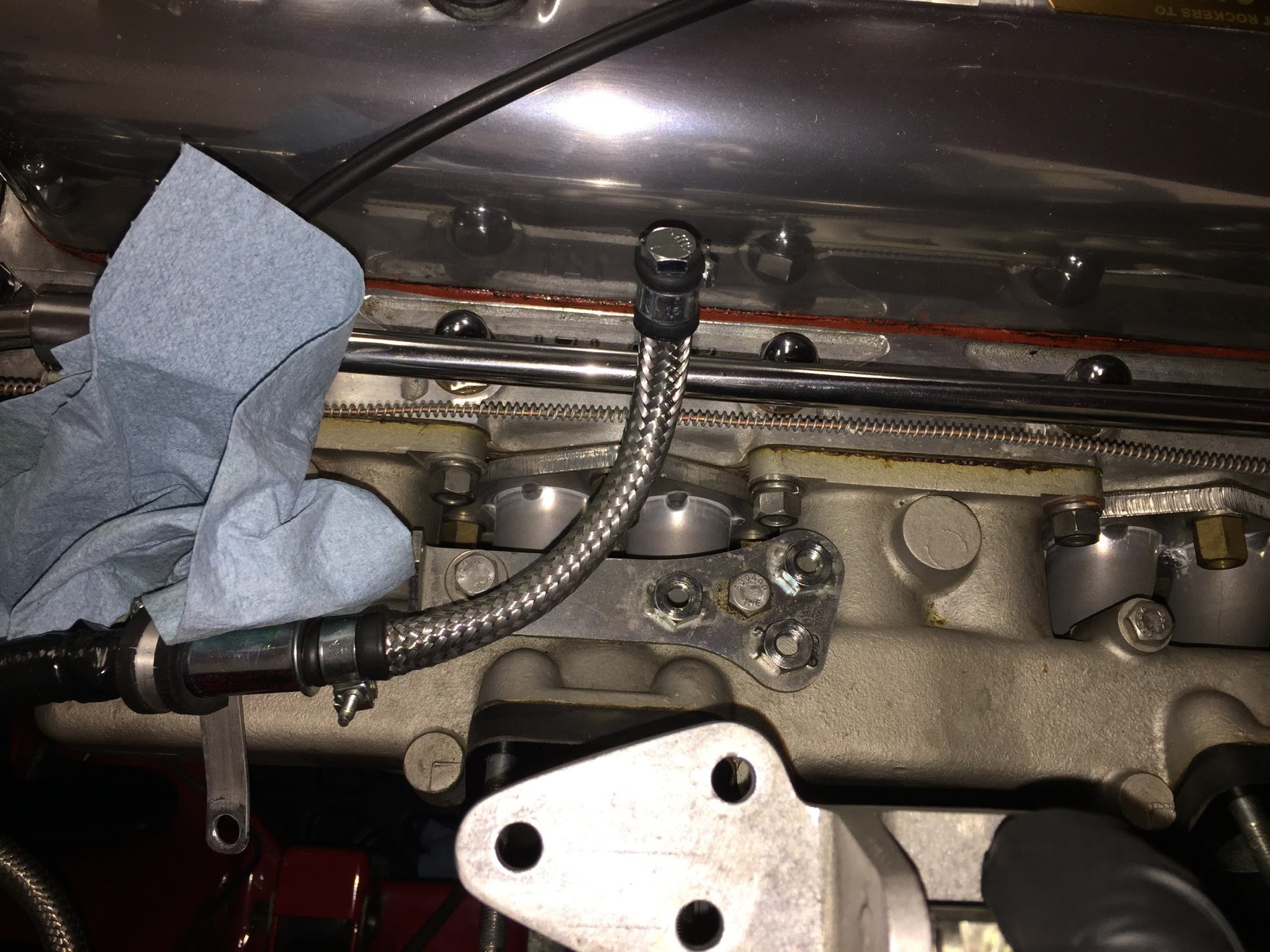
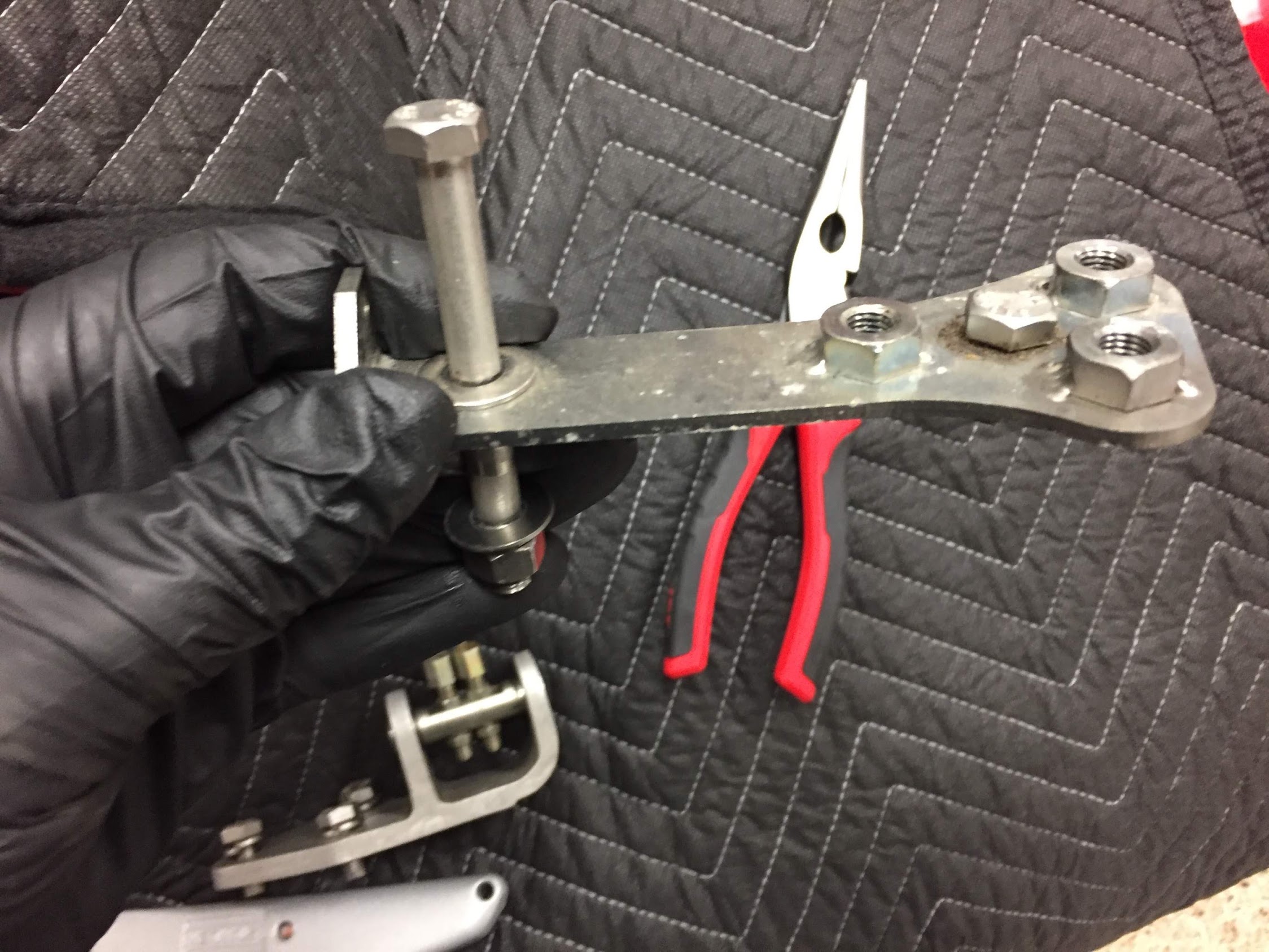
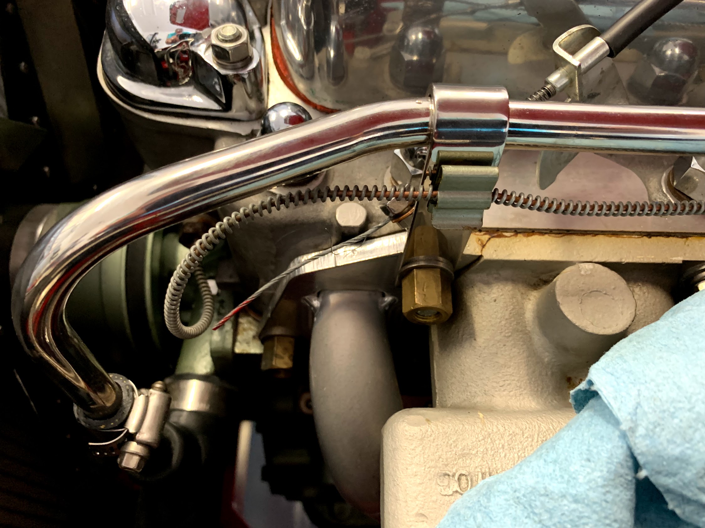
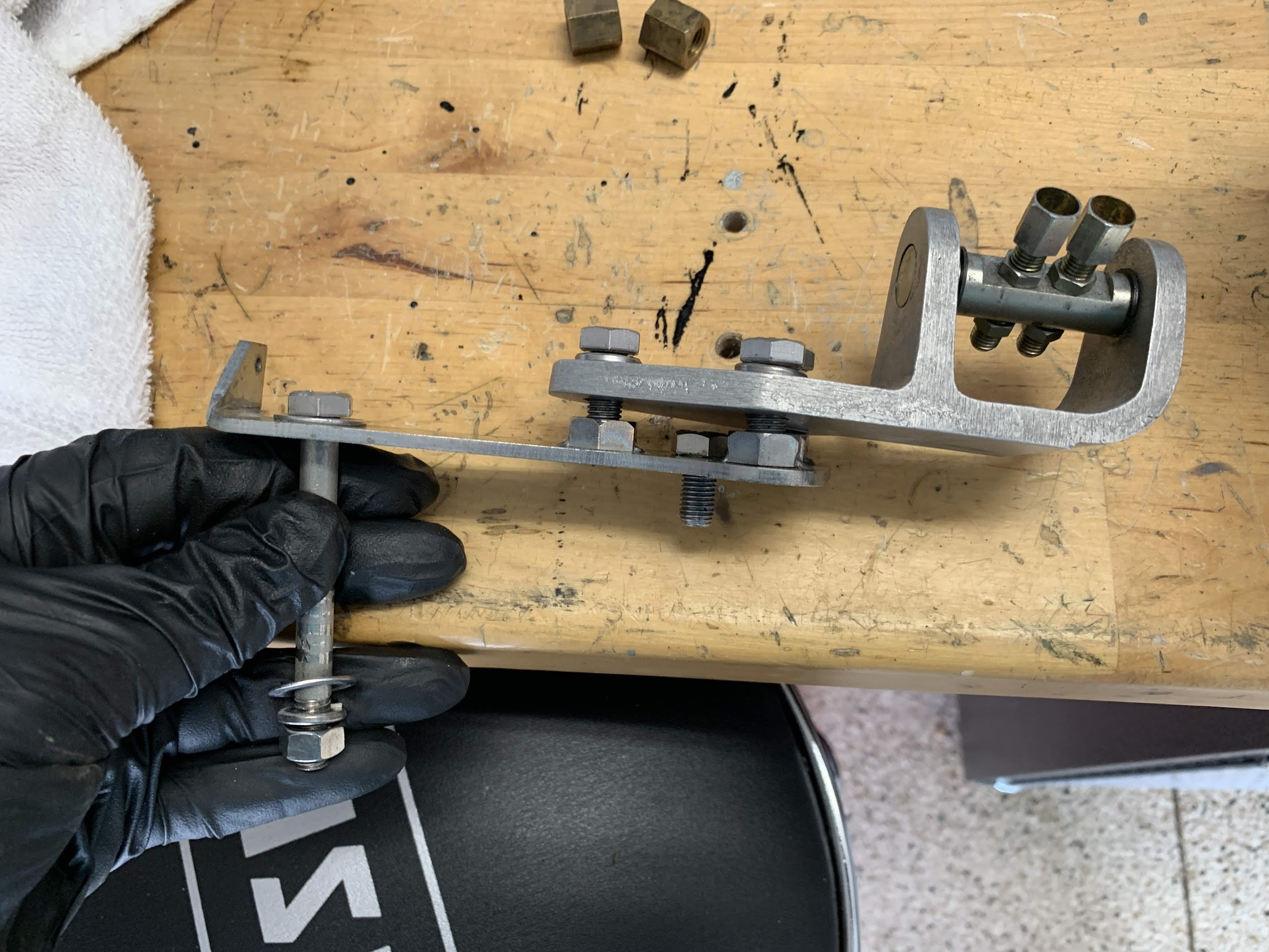
  • Modified the design of the throttle cable routing to the carburetors from the accelerator pedal.
  • New vinyl for the RH door shut face finisher panel side. Will replace the LH side at a later date.
  • Installed new ignition wires, rotor, and distributor cap and checked the ignition timing.
  • Added a bell housing drain hole for oil leaks from the rear main bearing.
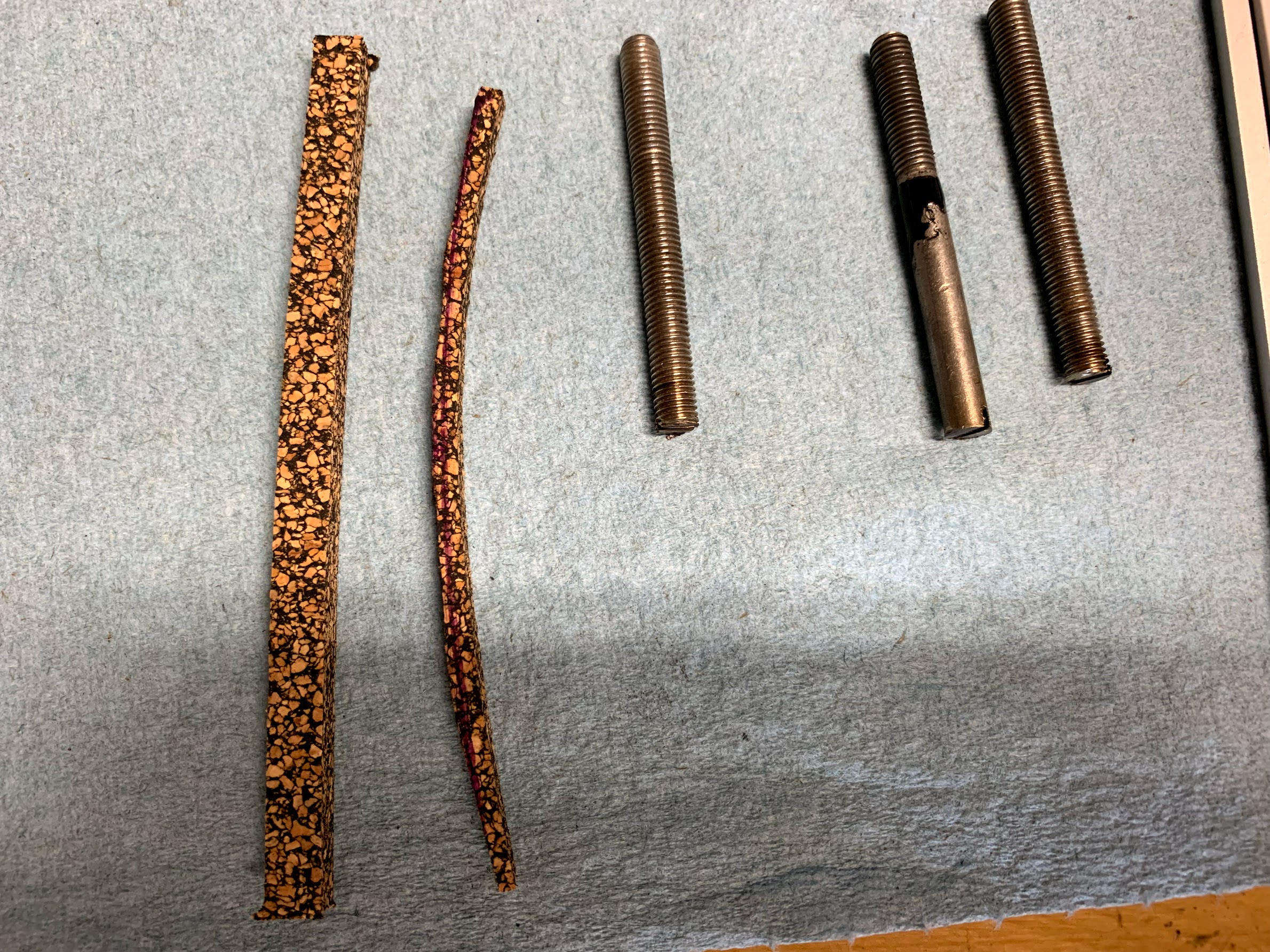
  • Replaced the water pump, mounting studs and gasket, fan belt, and upper and lower radiator hoses. Replaced the stainless steel flex fan with an asymmetric yellow plastic (nylon) fan sourced from AH Spares to reduce noise.
  • Replaced the 195 degree thermostat (for Virginia) with a 160 degree sleeved thermostat (for Florida) sourced from British Car Specialists.
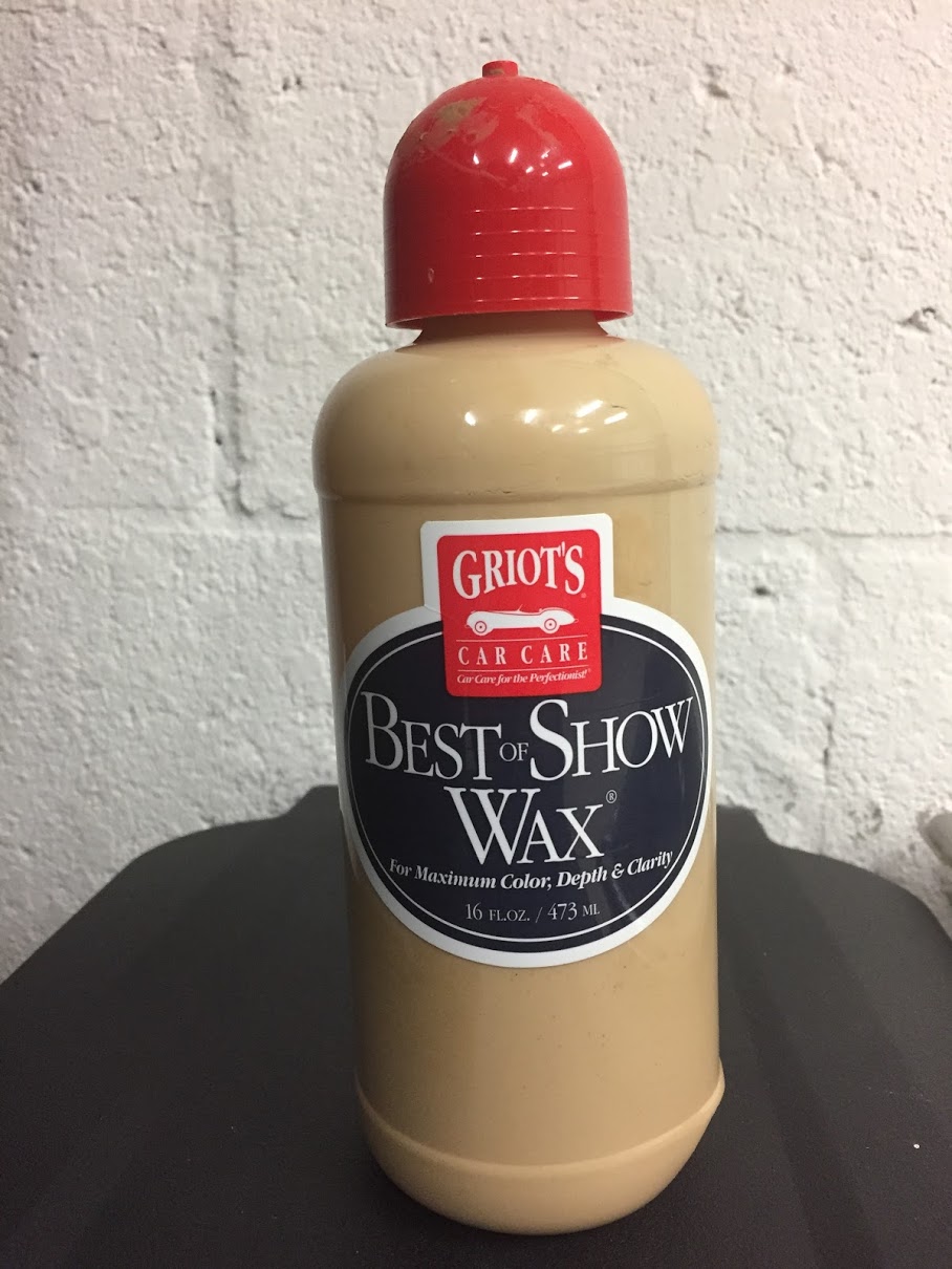
  • Washed, clayed, compounded, polished and waxed the car.

A few things yet to do:

  • Replace rubber in wiper arms.
  • Replace bristle flex draught excluders (door seal) – will complete when hardtop is off the car.

October 2018

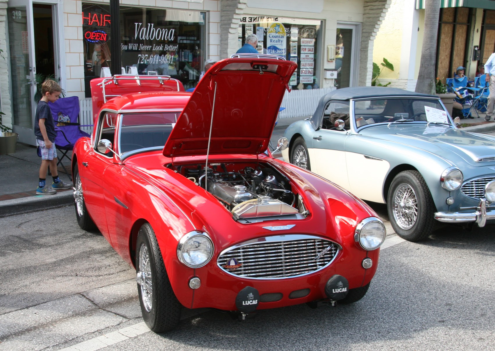
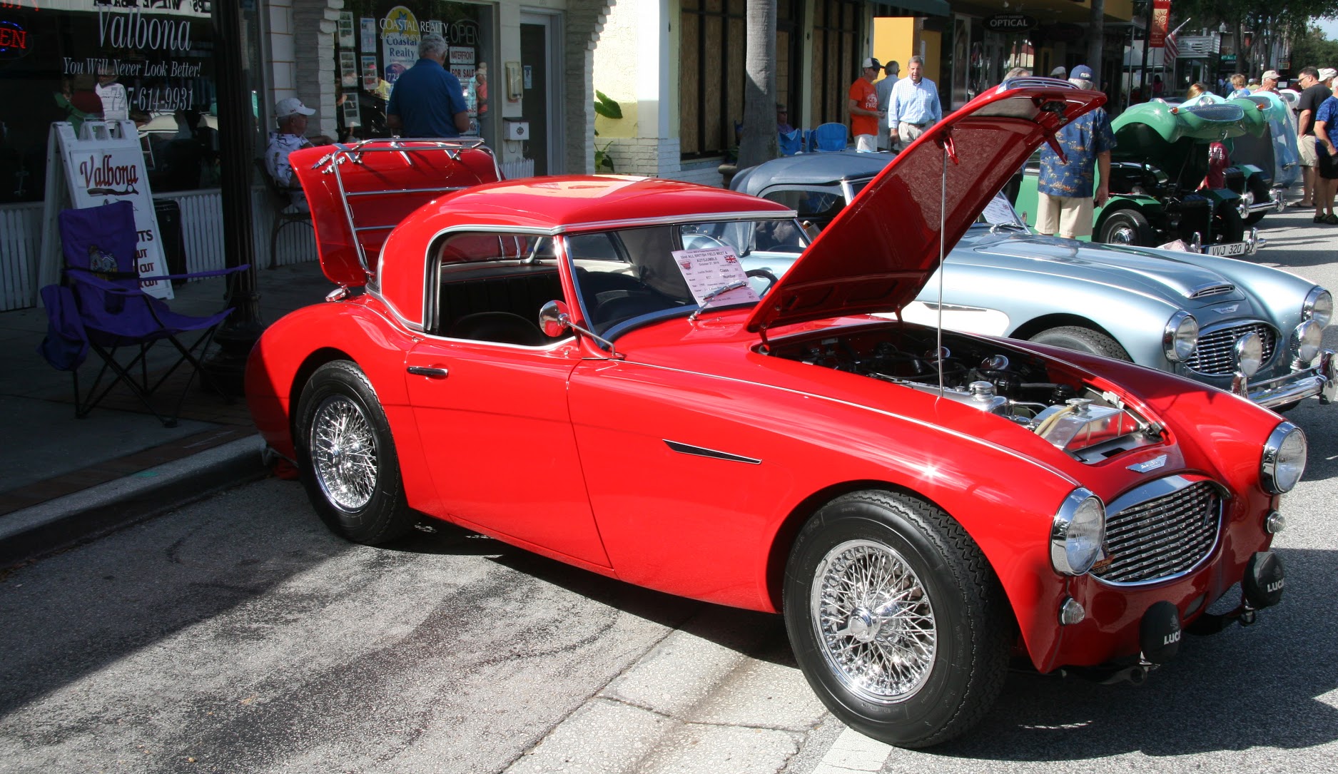
It has been approximately ten years since I wrapped up (if you ever really complete a restoration of a Healey) the restoration of the Bloody Beast. He has weathered the ten years quite well – better than me, that is for sure! I have taken good care of the Beast and completed periodic maintenance as one should. There have been a few things along the way that have required attention, such as the failure of the brake master cylinder that led to the replacement of both masters and the clutch slave cylinder while I was at it. However, for the most part, it has simply been fluid changes, tire replacements and etc.

I am sad to report that I have not driven the Healey as much as I should have during the time since I finished the restoration. About a month after I completed the restoration work I drove the Bloody Beast 8,000 miles in a cross-country trip from Rehoboth Beach, Delaware to California, up the coast to Victoria, BC and then back to Harrisonburg, VA. Between helping my son with his Bugeye, restoring a 1964 Jaguar MK2, and maintaining the 1987 Alfa, a 1969 MB 280SL and the Porsche in addition to the daily drivers there just wasn’t much time to drive! I am ashamed to say that I only put an additional 2,878 miles on the Healey in the ensuing nine-plus years. Driving, however, is the whole point of having a sports car and that is certainly true for an Austin Healey roadster. My son has now taken the Bugeye to his home. I have sold the Jaguar and the Mercedes. I now intend to spend more time driving the Bloody Beast!

After almost ten years I thought it might be healthy to go over the car carefully and examine the condition of components, check tolerances, and replace items that typically wear – even though they might be in operable condition at the moment. I will be making myself a list of items, that will probably not be in any particular order, and I will undertake some of the work as the list is added too over time. I will gradually need to accumulate parts for the work to be done.

For those who read this post, I hope you will contribute through your comments and make suggestions about anything, but particularly about items that should be added to my ten year renewal list. To be clear, an item on the list, an oil change for example, doesn’t mean that it is only to be done every ten years. I will make entries on this post chronologically as items are accomplished. I will keep a ten year renewal checklist as a separate post and add to it as I think about items to address. I will organize this list based on the categories of the Workshop Manual.

So, lets start this project! The most recent actions are listed first: Ten Year Renewal Blog

Fuel Hose Replacement

I have two fuel pumps installed in the Bloody Beast so that I have a back-up at the ready should one fail. I used a combination of steel pipe and rubber fuel hose to plumb the system between the tank, the fuel pumps and the hard fuel line to the front of the car. 

Rubber fuel hose doesn’t last forever and particularly with the introduction of ethanol fuels (I try to avoid ethanol fuel unless I have no choice) which can apparently break down rubber hose more quickly than non-ethanol fuel, I decided that as part of my ten year renewal process it was time to replace the hose.

I used what Moss Motors calls an “ethanol proof” 5/16 rubber hose, part #434-451 as the replacement hose. When I inspected the old hose once off the car it was definitely getting stiff and harder, but seemed to be in pretty good shape and didn’t show any signs of interior deterioration. Nevertheless, it is good to have new hose installed.

Minor job, but one more item on my checklist accomplished!

Ethanol Proof Fuel Hose

Car Show Preparation

The Tampa Bay Austin Healey Club hosts an annual British Car Show held in Safety Harbor, FL. The 2018 Show will be held on October 27 so I side-stepped my ten-year maintenance project and gave some attention to cosmetic issues to get The Bloody Beast ready for the show.

I had clayed, polished and waxed The Beast not too long ago, so this time I just washed and waxed her. I always use Griot’s Garage Best of Show wax. I think it is a great product. Super shine and very little residue. I apply with an orbital buffer (also Griot’s Garage) and remove with a micro-fiber cloth.

Best of Show Wax

The brightwork was cleaned and polished with Meguiar’s All Metal Polish. It produces a great finish. I use it on the stainless steel grill, the chrome and stainless steel wire wheels and on the body chrome.

Meguiar’s All Metal Polysh

I like to use SprayWay Cleaner for the glass. You need to make sure the glass is completely dry after using the cleaner but if you do it results in a clean and streakless appearance. 

SprayWay Glass Cleaner

In the interior I use Griot’s Garage interior cleaner on all of the vinyl surfaces and Lexol Leather Conditioner on the leather seats. I have used Lexol’s conditioner since the upholstery was new and it still looks that way! I wrapped up the interior with a good vacuuming.

Lexol Leather Conditioner

The tires were cleaned and then treated with Griot’s Tire Cleaner. This dressing provides a nice clean and smooth look without an “over-done” glossy shine.

Griots Vinyl & Rubber Dressing

The surfaces under the bonnet were in pretty good shape, but I used some of the Meguiar’s polish on the rocker cover, carb dashpots, and the aluminum radiator upper tank.

While under the bonnet I changed out the spark plugs. The used plugs were sootier than I like and I will address this issue later by examining the timing and carburetor richness. The plugs are gapped to .03″

NGK BP6ES Spark Plug


The Bloody Beast looked quite good for the show and her paint received many compliments. We brought home the Best in Class award. Not bad for a nine-year old restoration!

The Bloody Beast – 1960 AH BT7

The Bloody Beast – 1960 AH BT7


Oil Sump Oil Leak Repair

The cork gasket between the engine block and the oil sump (oil pan) has deteriorated and needs to be replaced. It appears that the gasoline flow from the intake manifold overflow pipes contributed to the problem. The oil sump is an aftermarket cast aluminum piece, not the original pressed steel pan. The sump was painted silver just before installing ten-eleven years ago. While it is off the car, I am going to have it blasted and ceramic coated to make it easier to keep clean. The coating is being done by a local firm, C2 Powder Coating in Bradenton, FL.

The first step was to drain the oil from the sump. While I will replace the oil with fresh, I decided to leave the K&N filter in place as it has only been on the car ten months and has only about 350 miles on it.

To remove the oil sump, I lowered the car on my lift to the lowest brake stop setting. This allowed me to access the sump while on the floor below the car with my floor jack and a few 2x4s. I removed all of the mounting bolts except four to support the sump on the block.

Twenty-two of the twenty-four mounting hex head bolts are 1/4″-28 x 1,” the two additional bolts are 1/4″-28 x 1 1/2″ and these are used to secure the clips used to route the intake manifold copper drain pipes. These two bolts require a nut to hold the clips. Each of the twenty four bolts use a flat washer and a split washer. Tom, at Tom’s Import Toy, recommends using internal star lock washers rather than split washers as the split washers require  greater torque to tighten them down than is required for the bolts. Others have suggested to me that 6-8 lbs. of torque is sufficient for the cork gasket.

Cast Aluminum Oil Sump Before Clean Up

Oil Sump Supported for Removal with Floor Jack

All but four Bolts Removed

I found that I needed to remove the ground strap connected to one of the bell housing/engine backplate bolts so that the sump would clear to fall free.


Ground Strap Interference

It will take about a week to have the sump coated so I sealed the bottom of the block to keep things clean.

Sealing the Block

C2 Powder Coating did a great job with the oil sump. It looks new and bright now rather than stained and tired.

Ceramic Coated Oil Sump

Steve Gerow posted that Tom’s Import Toys https://tomsimport.com/category/new-parts/gaskets/ sells nitrile oil sump gaskets as a modern replacement for the original cork gaskets. Since I was waiting for the ceramic coating anyway I decided to order the nitrile gasket and I was very pleased with the product. I am sure that it will hold up much better than the cork. I used Permatex Aviation Form-A-Gasket Sealant Liquid to seal the nitrile gasket to the oil sump.

Permatex Form A Gasket

After waiting a little while for the sealant to set and get tacky, I placed the gasket on the sump and used the bolts that mount the sump to the engine block to line up the holes for mounting later.

Nitrile Gasket

Nitrile Gasket Up Close

There are some fairly narrow cavities at the front and rear of the block. I had new cork gaskets to go into the slots, but they required some trimming before installation.

Cork Gaskets trimmed

Cork Gasket Installed

I made some guide screws from longer bolts by cutting the heads off and then slotting the new screws with a Dremel.

Fabricated Mounting Screws

Once lifted into approximate position using the floor jack, I then screwed the guides through three gasket/sump holes to line up the sump for mounting to the block. This worked quite well.

Oil Sump In Place For Mounting Bolts

I then secured the oil sump to the block with approximately twenty-five 1/4″-28 x 1″ machine bolts. A small clip with a rubber grommet is used to steady the front intake manifold copper overflow pipe. At this location a 1 1/12″ bolt is used with the accompanying washer and nut. I tightened the bolts securely but not so tight as to deform the nitrile gasket. After some use, I will inspect the seal and retighten if required.

To conclude the project, I installed the oil sump drain plug with a new copper crush washer and refilled the engine with seven quarts of oil. 

Oil Catch Can Installation

Our Austin Healeys did not come equipped with oil catch cans but they did have a method of addressing combustion “blow-by.” The image below, with the components outlined in red, depicts the components of the system.

A contaminated air/oil/fuel mix leaks down from an engine’s combustion chamber, around the piston and into the crankcase, where a build up of pressure occurs. This gaseous mix is vacated from the crankcase through a fitting on the middle tappet cover to a ninety degree rubber hose and metal tube, another short rubber hose and into the “T” pipe fitting on the top of the rocker cover. The other side of the “T” pipe fitting on the rocker cover uses a rubber hose to direct the gaseous mix to the rear carburetor where it can then be recirculated through the rear carb into the intake manifold.

Original Crankcase Breather Design

The consequence of the “blow-by” mix being reintroduced to the combustion chamber and spraying the mix onto the top of the pistons, spark plugs and the intake valves could be carbon build up leading to pre-ignition. In other words, while we go to great lengths to use high quality filtered fuel and oil, the Healey’s system introduces dirty waste products back into the engine. That just doesn’t seem like a desirable situation!

Properly designed oil catch cans address the problems cited above. The oil catch can has an input hose (or more) to collect the contaminated gas and through a system of baffles/filters separates the liquid from the gas. The clean vapor exits the catch can through an air filter and into the atmosphere. Again, if properly designed, this air is relatively clean. The dirty liquid mix works its way to  the bottom of the catch can where it is collected and periodically drained off. 

So, if this is such a good thing to do for our engines why don’t all cars have catch cans? You usually only see them installed as aftermarket items on performance vehicles or collector cars. The answer is probably as simple as extra cost to the manufacturer and the creation of one more maintenance factor (draining the collected oil/fuel mix) for the vehicle owner.

After only forty-seven years of ownership I decided to “fix” this issue! There are many catch cans on the market, some demonstrate pretty sophisticated engineering while others don’t do much more than “catch the oil” as the name suggests. One more example of you get what you pay for.

I decided to go with a universal oil catch can designed and manufactured by Mishimoto, Model # MMBCC-MSTWO. I ordered it directly from Mishimoto. I like this unit because of its diminutive size, easy mounting, and great filtering design. Other catch cans will work equally well, I am sure.

Mishimoto Universal Catch Can

Mishimoto’s black anodized aluminum mid-size can has two baffles to minimize oil slosh and a 50 micron bronze filter to release clean air to the environment. The can is 3.8″ tall and has a diameter of 2.5″. The inlet, outlet and drain plug holes are all 3/8″ NPT. It holds two ounces of liquid and is easy to take apart to clean with soap and water. It comes with two plastic 1/2″ barbed hose fittings. Mishimoto also markets a Petcock drain kit for this can that I also purchased.

Mishimoto Drain Petcock Kit


Once the catch can decision was made my attention turned to the plumbing required to make the system work in an already very tight Austin-Healey engine bay. I have never been fond of the appearance of the rubber hose exiting the rocker cover to the rear carb. Cape Sport International came up with the solution to my esthetic concerns – all a matter of personal taste.

Their product is part number AEC2041CSF2 and it offers an alternative to the original “T” pipe fitting. Their “U” pipe fitting allows one to easily route to outlets from the rocker cover to the right side of the engine bay. The piece is nicely made and is chromed. It looks like this once installed:

Capesport “U” Breather pipe

These are the components used in my catch can system for the Bloody Beast:

Bloody Beast Catch Can System, Part One

Bloody Beast Catch Can System, Part Two

I used the brass fitting on the bottom of the can because I had it. Apologize for the variance from the black aluminum.

I will substitute a chrome crankcase breather pipe for the stainless steel pipe when I have the chance to get one chromed to match what I have in the car now.

So here is the final installation of the Mishimoto Catch Can and all of its related plumbing. Pay no attention to the hose clamps. They will all be changed when my new clamps arrive from Australia! See note and reference below. As you can see in the image below the catch can is tucked behind the shroud support and under the RH fender. I simply turned a second crankcase breather pipe horizontally to route the emissions rubber hose to the catch can to avoid a rubber hose lying haphazardly across the right hand side of the engine bay.

Catch Can Mounting Bracket and Pipe Stanchion

Pipe Stanchion

Hose and Pipe Routing to Catch Can

Hose and Pipe Routing to Catch Can 2

Drain Hose and Valve

The Norma hose clamps look great. I saw these on Doug Escriva’s Healey 100-6 race car and had to duplicate the look – no way to duplicate the car! These clamps are apparently made in Germany but the only place I could find to source them was in Australia- go figure! http://www.norma.net.au/products/hose-clamps/norma/normaclamp-gbs-heavy-duty-hose-clamps/normaclamp-gbs-heavy-duty-hose-clamps

Doug Escriva Norma Hose Clamps

I received the Norma GBS Heavy Duty Bolt Clamps 21-23 mm W4 – All 304 Stainless Steel hose clamps, part #GBS22/18W4, from Auto Parts Wholesalers in Australia and they met expectations! In addition to being very functional and easy to use, they also look great. So here they are on the Bloody Beast:

Norma Clamps 21-23 mm 


Crankcase breather pipe hose and norma clamps


Norma Stainless Clamps Installed


Carb Removal and Intake Manifold Replacement

So, here is a step-by-step of the process from tear down to completion. More than anyone (except me) would want to know. I first removed the air cleaner that I have been using for ten years from the carbs. Next was removal of the throttle return springs with a note about orientation of the springs on the lever and the intake bracket:

I had installed a fuel filter in the fuel line to the front carb. I removed the nut securing the filter bracket to the intake stud and then loosened the clamp at the front carb banjo and lifted the fuel line out of the way:

Front Throttle Return Spring

Then the hose connecting the two carbs could be removed:

Fuel Hose Filter Mount

Banjos and Connecting Hose

I then removed the choke brackets from each of the Carburetters and loosened the cable retaining nut on each of the chicken levers, so that the cables were free. There are three (3) ballpoint pens springs in the cable to make the cable retract. I left the spring-loaded cable in tact.

Rear Choke Cable and Bracket

The rubber hoses from the overflow pipes at the float bowls were then removed. The float bowl banjo nuts are removed with a 1/4 inch Wentworth wrench. The hoses run through a hole in the insulated het shield.

Overflow tubes removed from float bowl drain pipes

I then disconnected the vacuum line at the rear carburetor that connects to the distributor.

Carb Ported Vacuum Line

The next step was to disconnect the throttle cable from the throttle lever located between the carbs.

Throttle Cable and Lever

Throttle Cable and Lever Orientation

The cruise control chain was then disconnected from its throttle shaft lever. The relative clock location of the cruise control lever and the throttle shaft lever were noted.

Cruise Control Lever and Chain

With all of those components disconnected, it is then possible to remove the carbs from the intake manifold. This is done by loosening and removing eight 5/16″-24 hex head nuts, flat washers and lock washers from the manifold studs. By the way, getting to the lower studs can be a challenge! Before lifting away the carbs and float bowls check to see if the float bowls are empty of fuel.

Carbs removed from eight intake studs

It is then possible to remove the heat shield from the manifold. There is a gasket on each side of the heats shield between the carb and the heat shield and between the heat shield and the manifold. 

My intake manifold had a crack in the front mounting ear. It can be seen in the upper left of the image above. I located another used manifold from Michael Salter. I had the manifold Jet-Hot coated which gave it an almost chrome appearance. So while the carbs were being tended to, it was the perfect time to go ahead and replace the manifold. Several steps are needed to remove the manifold.

First was to detach the vacuum hose from the rear port on the intake that is used for the cruise control.

Vacuum Port for Cruise Control

Custom Vacuum Port for Cruise Control

I then removed the front choke cable from the throttle bracket on the intake manifold.

Choke Cable and Bracket Mount to Intake Manifold

The next step is to remove the remaining two bolts that hold the throttle cable bracket to the intake manifold. This will reveal the lower bracket which has two mounting bolts to the intake manifold.

Upper Portion of the Throttle Bracket

Lower Portion of Throttle Bracket

Then remove the two bolts holding the lower bracket. Lift away the lower bracket. The rear bolt is only about a half inch long. But the front bolt extends through the intake manifold and has a nut on the reverse side.

Lower Portion of Throttle Bracket Removed

The water pipe for the heater is mounted in two locations and these must be loosened to permit the removal of the intake manifold. This requires loosening the clamp on the radiator hose extension. You lose a little coolant, but not too much. The pipe can then be lifted aside allowing access to the manifold. I also unclipped the water temperature sensor cable from its clips. In the image below it is easy to see the crack in the manifold ear.

Front Heater Pipe Mount

Rear Heater Pipe Mount

The nine nuts, flat washers and lock washers could then be loosened and removed allowing the removal of the manifold. The front and rear mounting points for the intake share a brass nut fixing the exhaust headers to the head. I noticed that the exhaust header mounting plate is not quite as wide as the intake mounting plate which probably stressed the aluminum intake ear, hence the crack. On the newly prepared intake manifold, I filed the forward and rear mounting ears down so that they aligned nicely with the exhaust headers. This should prevent cracks in the future.

I had saved my original iron cylinder head and it came in handy on my workbench for setting up the intake manifold and carbs. The weight of the head supports everything and makes mocking up everything and adding intake components much easier than working in the car!

Original Iron Head with Newly Prepared Intake

I double-nutted and removed the carb mounting studs from the old manifold and installed them in the new manifold after chasing all of the threads to clean them out. I used compressed air to blow out all of the stud mounting points.

Removing Studs from Old Intake Manifold

After installing each of the studs into the intake manifold I placed one gasket and then the spacer block on the manifold.

Studs, Gaskets, and Spacer Blocks Installed

I removed the fitting for the vacuum used for the cruise control from the old manifold and reinstalled it in the new manifold with thread sealant and a new copper crush washer.

Vacuum Fitting for Cruise Control Installed

And, then replaced the rear vacuum port plug that screws into the threaded hole in the manifold.

Rear Vacuum Port Threaded Plug

I then transfered the two 5/16 inch bolts that go through the intake manifold and originally mounted to the exhaust manifolds. Since my car uses exhaust headers these mounting points or not used, so I simply install bolts and nuts into the car holes.

Unused Mounting Bolts to Original Exhaust Manifold

The original intake manifold design incorporates two fittings for fuel drain lines. I used both for the past ten years, but I decided to plug the rear drain hole with this rebuild. I really don’t know if there will be negative consequences to this or not. I did this because the rear drain line was extremely close to the rear header pipe. I just didn’t like that little copper pipe being so close – less that 1/8″ – from a hot exhaust pipe. 

I am aware that some after market intake manifolds do not include the drain line fittings so I hope that this suggests that these drain lines may not be required? The image below shows the brass pipe fitting installed in the manifold.

Intake Manifold Drain Fitting

I then remounted the Dennis Welch Throttle Cable Bracket to the manifold.

Dennis Welch Throttle Bracket

Dennis Welch Throttle bracket Installed

During some down time in this process I cleaned up the heat shield and repainted it.

Refurbished Carb Heat Shield

I then put two new gaskets on each of the inlets in the manifold for the mounting of the heat shield.

Heat Shield Gaskets Installed on Intake Manifold

I then mounted the heat shield and added two more gaskets for the carburetors.

Heat Shield Gaskets to Carbs

At this point, I was ready to install the rebuilt carburetors to be described in the next post.

Front Shroud Badge Replacement

They just don’t make them like they used to! The shroud badge I mounted on the Healey around 2008 started to lose its color (enamel?) this year. I think the problem was that the entire badge was chromed and then the enamel was applied. It is hard for anything to stick to chrome indefinitely. So, my 2008 badge wasn’t as good as the original.

Shroud Badge Losing Enamel

But…the badges available now are not as nice as the ones that were available when I did the restoration. I had to return one vendor’s badge that wasn’t very good at all. I then ordered one from AH Spares, part # BAD-107, and while the metal is thinner than the one it is replacing, it does have the curvature of the shroud and the lettering and enamel look pretty good. We will see how long the enamel holds up on this badge! The badge has two studs and came with the fixing washers and nuts – a 5/16″ wrench is used.

Replacement Shroud Badge

Replacing leaking RH Lever Shock

I use Bilstein tube shocks on my car having installed Udo Putzke’s mounting kit when the the car was restored. Details may be reviewed on a previous post https://valvechatter.com/?p=3365 regarding the front and rear suspension. The kit uses the original lever shocks without the pistons as the upper “A” arm of the front suspension. The right front shock was leaking oil. 

I returned the shock to World Wide Auto Parts run by Dave Caldwell. Dave had rebuilt my shocks about ten years ago. In spite of the time that has passed, Dave honored the lifetime warranty and sent a fresh rebuild to me. Amazing!

To replace the shock, I first placed the car on four jack stands and then removed the right front wheel.

On Jack Stands for Shock Replacement

I then placed a floor jack under the spring pan and raised the pan until the shock arm was free of the rubber rebound pad.

Floor Jack to go Under Spring Pan

I then loosened the top mount for the bilstein tube shock using a 3/4” wrench and loosened the lower mount for the bilstein tube shock with 5/8” wrenches.

Bilstein Shock Lower Mount

I then removed the split pin on the castle nut securing the fulcrum pin.

Split Pin in Castle Nut

I then progressively loosened the castle nut and used it to tap out the pin with a soft hammer.

Gradually Knocking the Fulcrum Pin Out

Then using a drift I tapped out the bolt all of the way, leaving the drift in its place.

Fulcrum Pin Removed

Using a large screwdriver I levered the trunnion for the king pen off of the shock absorber.

Screw Driver as Pry Bar

It won’t move far, but I put a large jackstand under the hub to prevent any stress.

Jack Stand Supporting the King Pin and Trunnion

Using a 9/16” socket and ratchet I loosened and remove the right front shock bolt to chassis.

Loosening Front Shock Bolt

Then using an Allen wrench through the access hole in the bracket, I loosened and removed the left front shock bolt to chassis.

Allen wrench to Remove Left front Shock Mount

I then removed the left-hand rear and the right-hand rear shock bolts to the chassis with a 9/16 inch deep socket and ratchet.

Removing Rear Shock Mount Bolts

I was then able to lift the shock away from the car. It was immediately obvious that the shock had been leaking!

Obvious Oil Leak

The next step is to clean up the mounting area before installing the new shock.

Clean and Ready for New Shock

I then loosened the shock arm bolt/nut 9/16” wrench to make it easier from the arms to go over the trunnion bushings.

Loosen Shock Arm Bolt

The next step is to install the new shock to the chassis by first screwing in both of the engine side (rear) bolts. These are grade 8 3/8”-24 x 1 1/4”. This is made easier with some long extensions and a universal joint before the socket.

Long Extension and Universal

In this case, the completion of the installation really is the reverse of the removal process!


Rear Rally Overrider Modification

I have never been happy with the Rally Overrider brackets I installed during the restoration process for the Bloody Beast. I ordered the brackets from Cape International and while they fit (I guess), the Rally Bumpers protruded too far from the rear shroud.

Cape International Rally Overrider Brackets

I had resigned myself to finally solve the problem with some cutting and welding. However, I met a new Healey enthusiast who was just finishing up his restoration and he mentioned to me that he had purchased his Rally Overrider brackets from AH Spares and that he was pleased with them. He showed me a few photos and I was sold. I ordered a pair of the brackets from AH Spares for $73.00.

It was immediately obvious upon inspection that the AH Spares brackets were shorter and the angle of the brackets where they mount with the Overrider was also considerably different. The AH Spares bracket is laying on top of the Cape International bracket in the photo below. The much sharper angle on the AH Spares bracket tucks the rally bumper up and under the shroud nicely, paralleling the shroud curvature.

Old and New Brackets

I decided to replace the RH side bracket first. The initial step in the replacement process was to remove the battery and just to make things a little easier I also removed the master ground switch near the battery. This provided access to the two 3/8″ bolts that secure the bracket to the frame of the car.

Battery and Master Ground Switch

With the battery removed one can see the forward bolt for the bracket mount:

Battery Brace and Forward Bracket bolt

To get to the rear-most bracket bolt I removed the master ground switch:

Master Ground Switch

It was then just a matter of bolting the rally bumper to the bracket and sliding the assembly into place. I then tightened all of the bolts, replaced the battery and tray as well as the master ground switch. I then moved to the left side of the boot.

Of course, to access the LH bracket one must remove the spare tire!

Spare Tire Removal

I then installed the LH bracket and rally overrider as I had done the RH side and replaced the spare tire and cover. While I was at it, I checked the air pressure in the spare and found it to be 11 pounds so I topped that up to 30 and was glad for the reminder to check spare air pressure!

I am quite happy with the finished product. The rally overrider bumpers now fit as they should and I think it is a much better look.

Rally Overrider with AH Spares bracket

New Overrider brackets Installed

Rear View of New Rally Overrider Install

One more task completed and checked off the list!


Engine Oil Change

A pretty simple and straightforward first step. I have a spin-on oil filter adapter and use a K&N HP-2009 Filter with a little under 7 quarts of Hick’s Oils Collector’s Choice 20W-50 motor oil. A fresh copper crush washer was used under the oil sump drain plug. The drain plug on my aluminum sump requires an 11/16″ wrench for removal.

I ordered the oil from Moss Motors and the filters directly from K&N. You don’t need a filter removal tool for the K&N filter as the canister comes complete with a 1″ wrench fitting! 

K&N HP-2009 Oil Filter


Hick’s Oils Collector’s Choice 20W-50