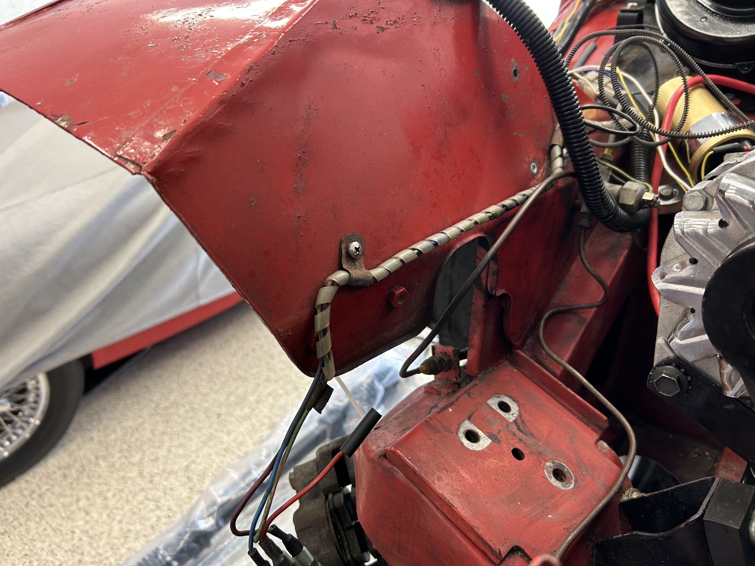
Steering Rack – Our next step is to remove the steering rack. We are going to replace the old rack with a new one from AH Spares. The tie rod ends were previously disconnected from the steering arms so this was just a matter of disconnecting the steering columns and removing the two aluminum brackets that secure the rack assembly to the chassis crossbar. To get to the rack we did have to remove the coolant overflow tank from the LH inner finder valance that was fastened to the inner fender with 1/4″ – 28 x 1/2″ hex head bolts and nuts.
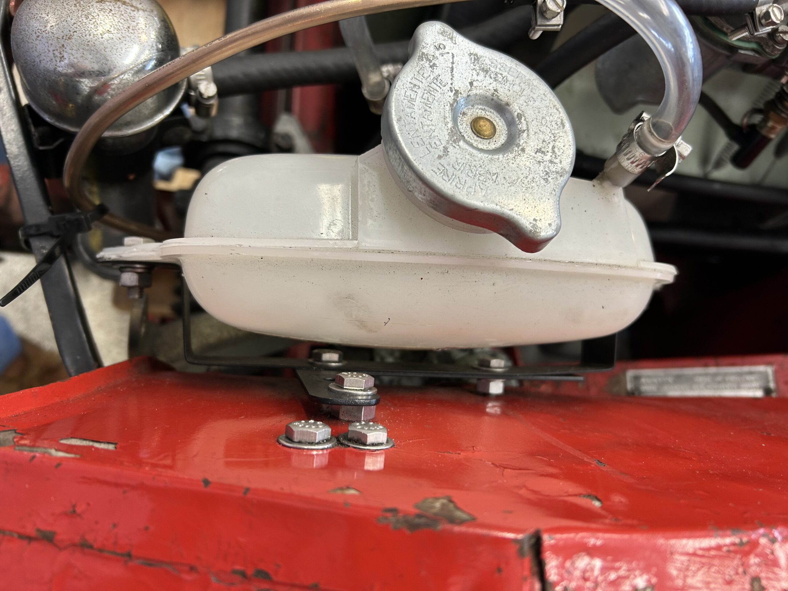
Coolant Expansion Tank
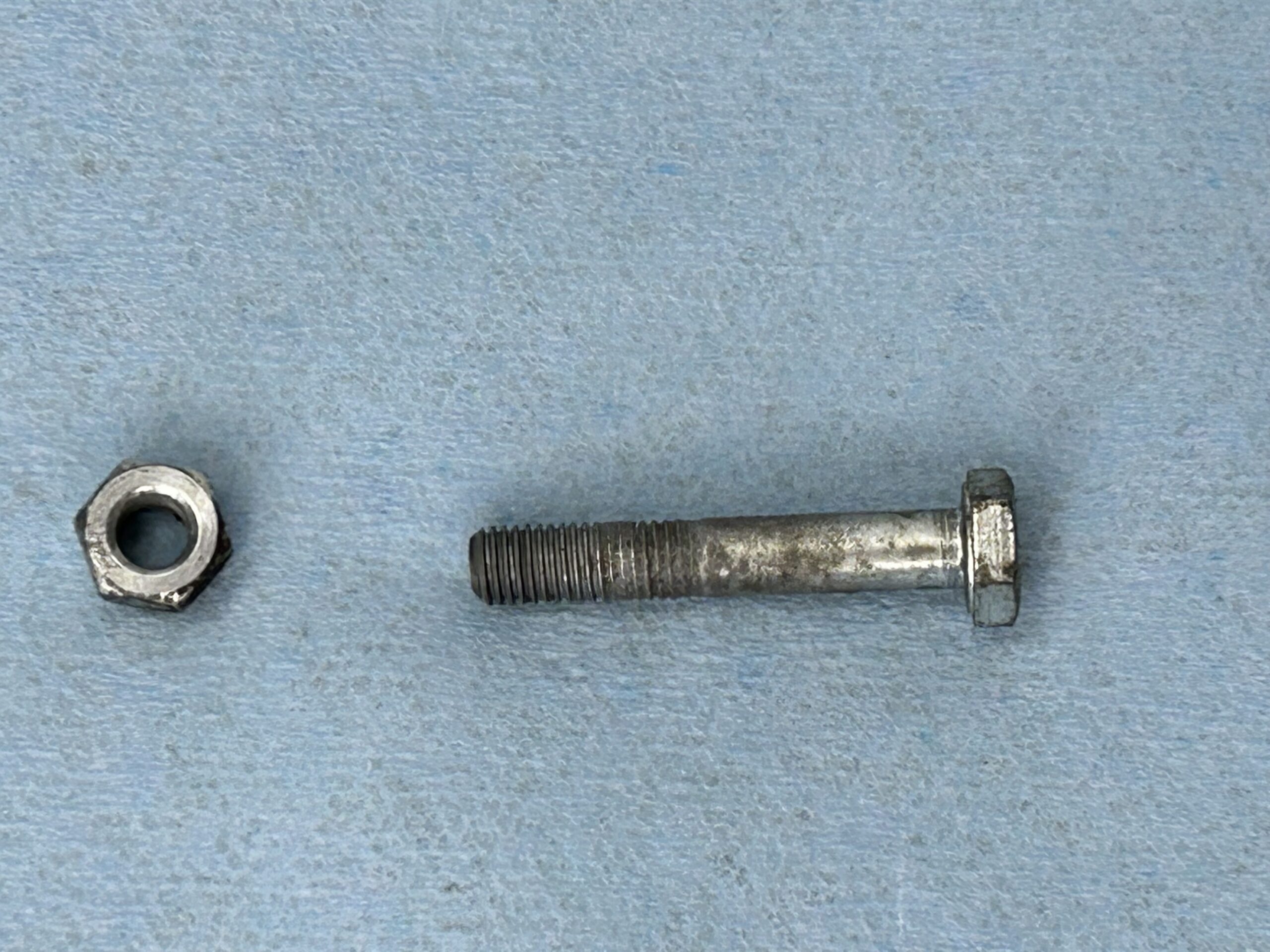
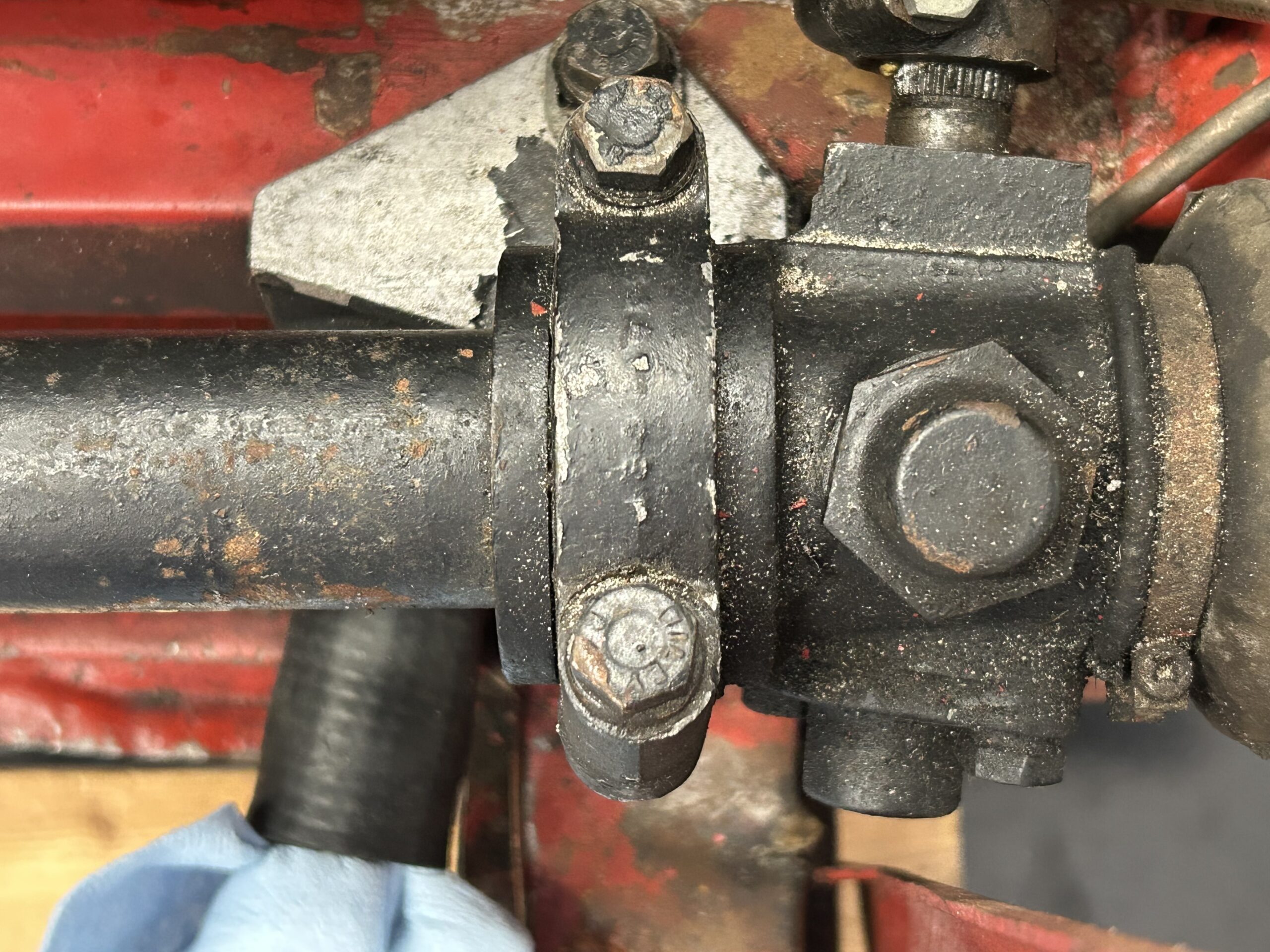
The steering column was then disconnected from the steering rack by removing the special pinch bolt and nut from the column. Note that the bolt fits through the indentation groove in the steering shaft.
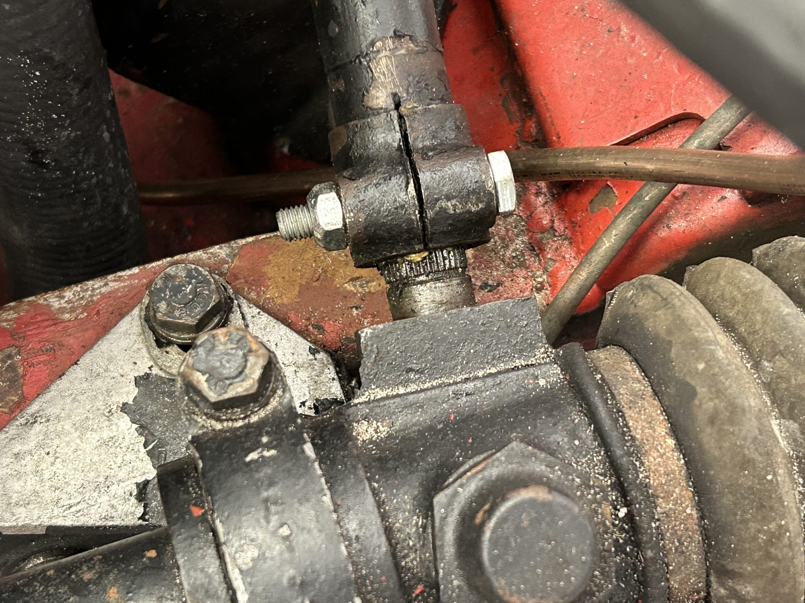
Steering column Pinch Bolt to Rack
Steering column pinch bolt
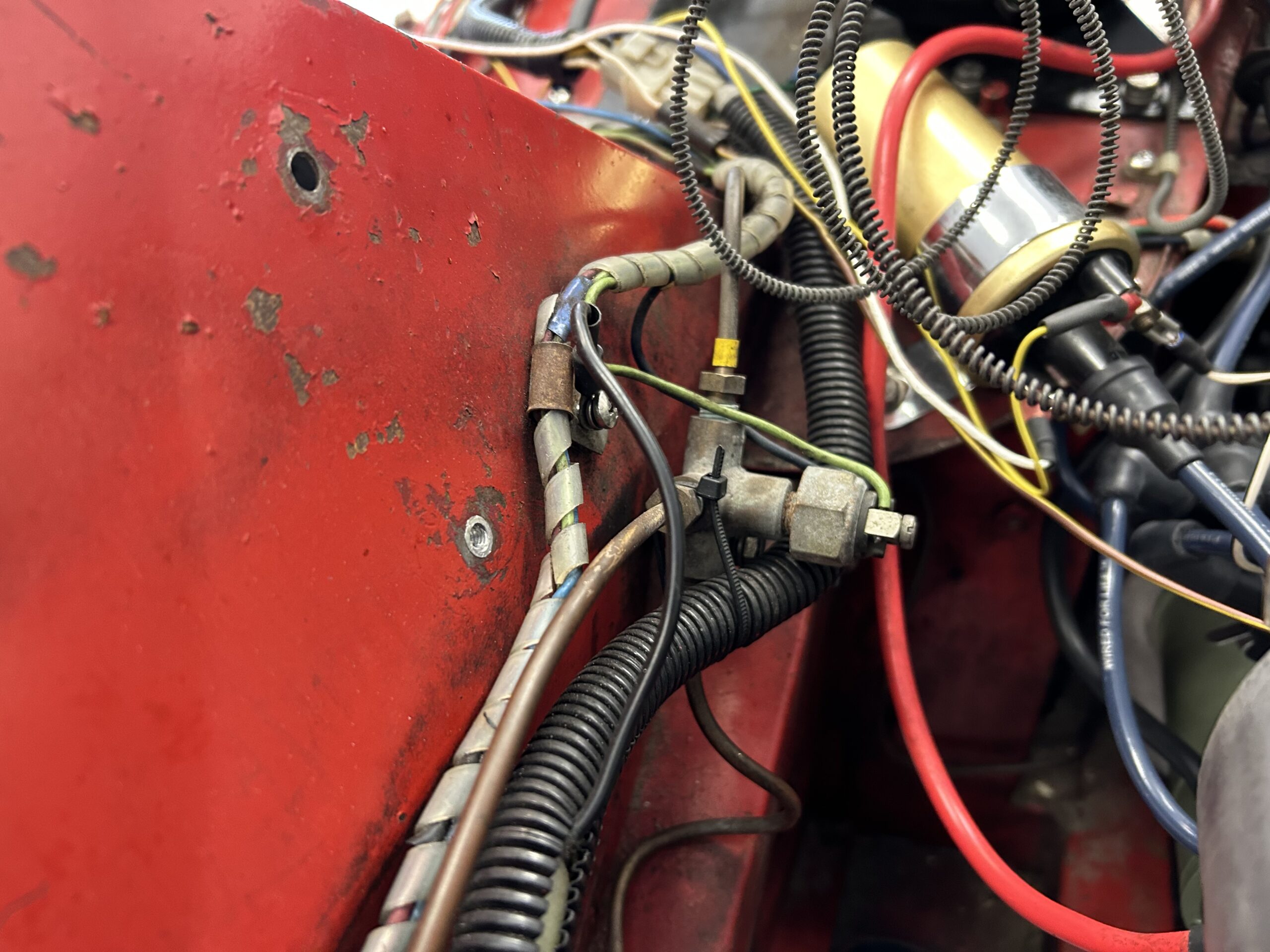
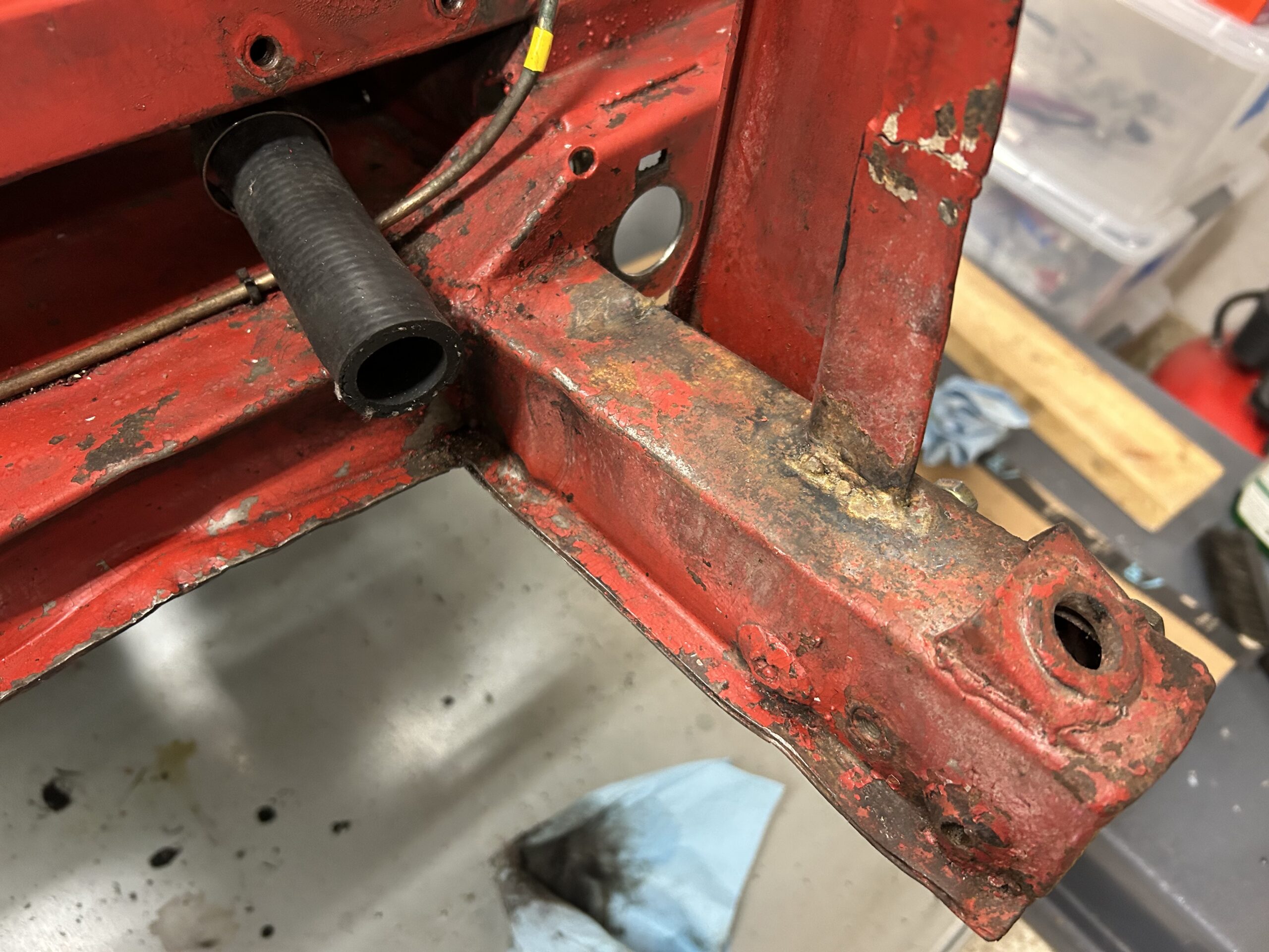
The steering rack brackets are aluminum and consist of a lower piece with a cap. Once the caps were removed, the steering rack assembly could be lifted away.
LH Steering Rack Bracket
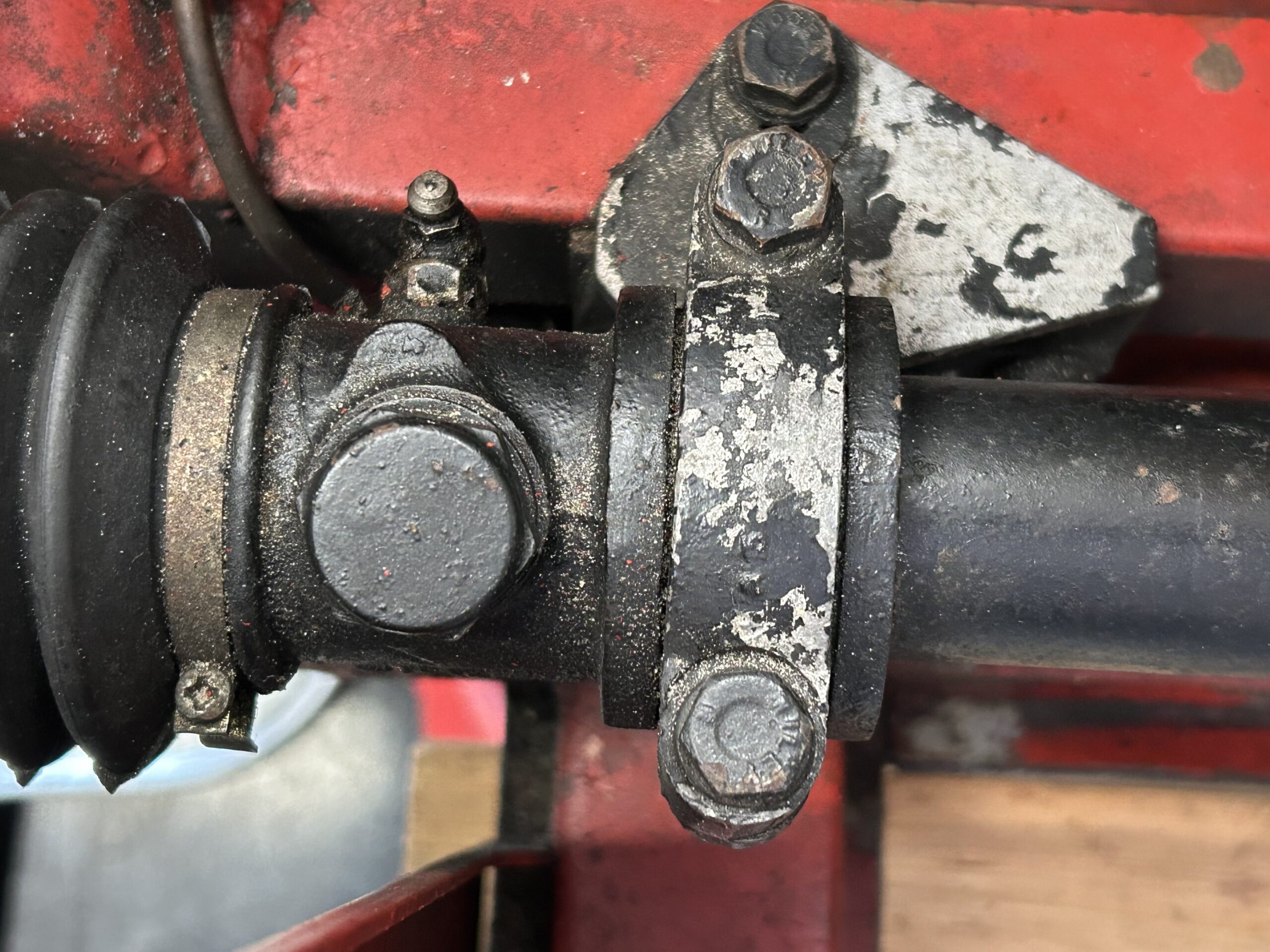
RH Steering Rack Bracket

Steering rack bracket caps
LH Steering Rack Lower Bracket

RH Steering Rack Lower Bracket
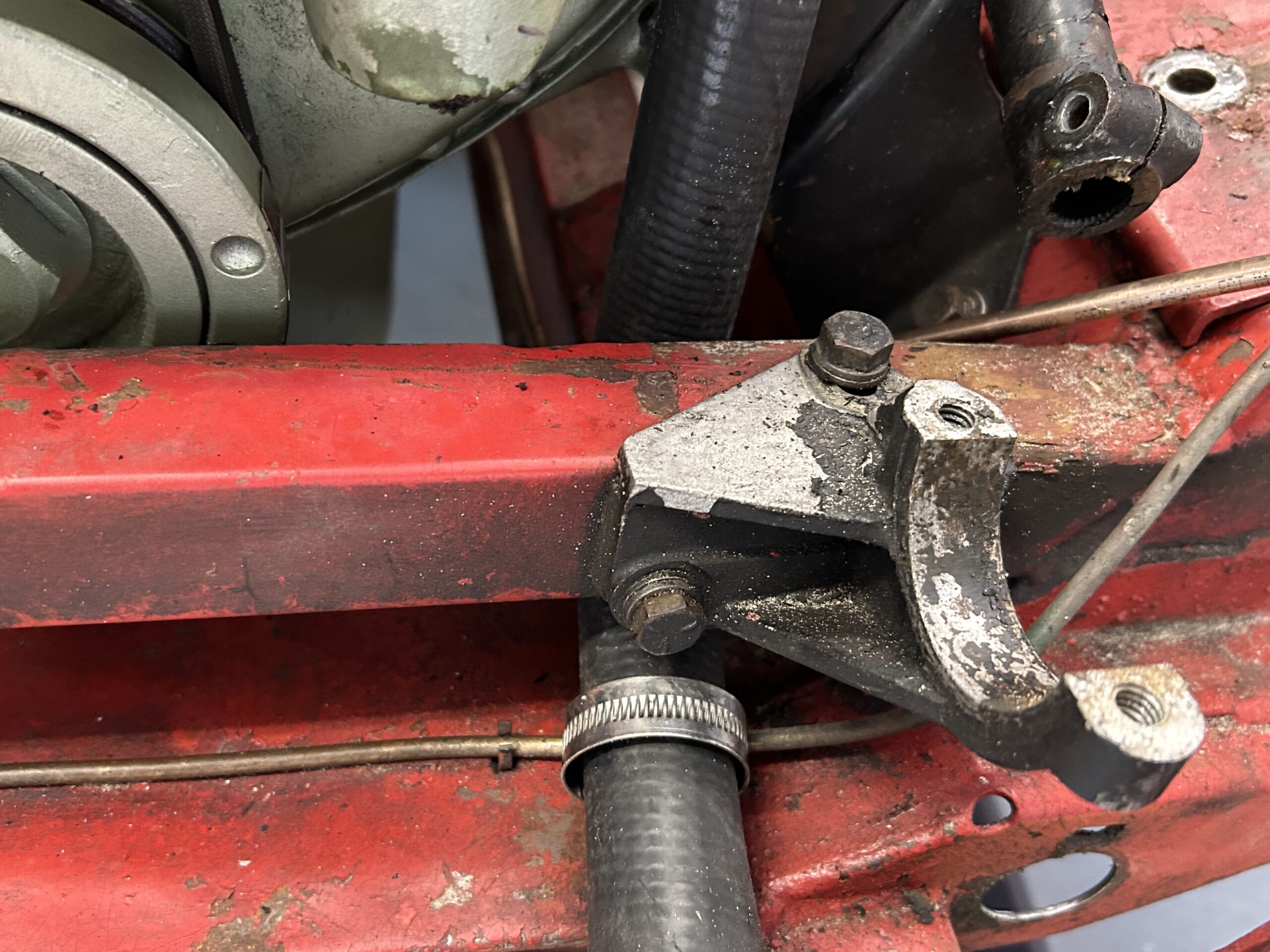
On a left hand drive car, there is supposed to be a shim on the lower right hand bracket and we did find that to be in place. To our surprise there were two aluminum shims on the left hand lower bracket. These were apparently installed to compensate for the damage to the chassis crossbar. This will need to be investigated further at a later time.
RH Steering Rack bracket with one steel shim
LH Steering Rack Bracket with two aluminum shims
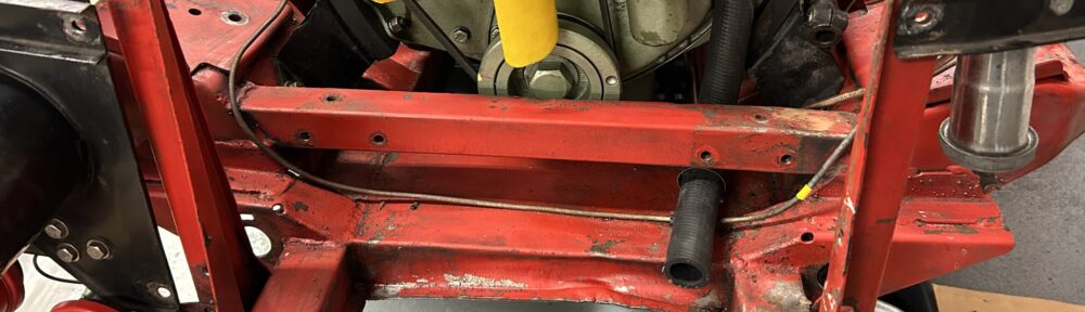
With most of the front suspension components removed and out of the way, it is time to clean up the front of the chassis and get rid of the grease and grime. This looks much better than it did!

Cleaned Chassis crossmember
Video Episode Twenty-nine shows the removal of parts and the clean-up of the front of the chassis. The front shocks, the steering rack and its mounting brackets are removed. The rebuilt front shocks from World Wide Imports are received and painted. The fresh air intake and its mounting braces are removed. The horn wiring harness is disconnected from the horn relay and horns, and the horns are removed from the car. The location of the horn wiring harness clips is shown. Unfortunately, some damage to the front chassis is discovered and pointed out.
https://vimeo.com/791725643/86659de9f0
The following steps are addressed in the video:
0:00 – Front shock removal
0:20 – Steering rack removal
0:46 – Steering column pinch bolt
1:02 – Steering rack chassis brackets
2:25 – Steering rack chassis crossbar damage
3:20 – Rebuilt front shocks
4:33 – Front of chassis clean-up
5:35 – Fresh air intake removal
6:00 – Horn relay wiring and wiring harness
7:48 – Chassis/Inner finder brace removal
8:22 – Horn removal
9:12 – Horn wiring harness and clips
9:48 – Lights and electric radiator fan wiring harness
10:15 – Front of chassis clean-up complete
The front shocks were rebuilt by Jane and Peter Caldwell at World Wide Auto Parts. They do a great job with refurbishing the lever shocks. We are going to revert to these and give them a try before possibly reinstalling the front Bilstein tube shocks.
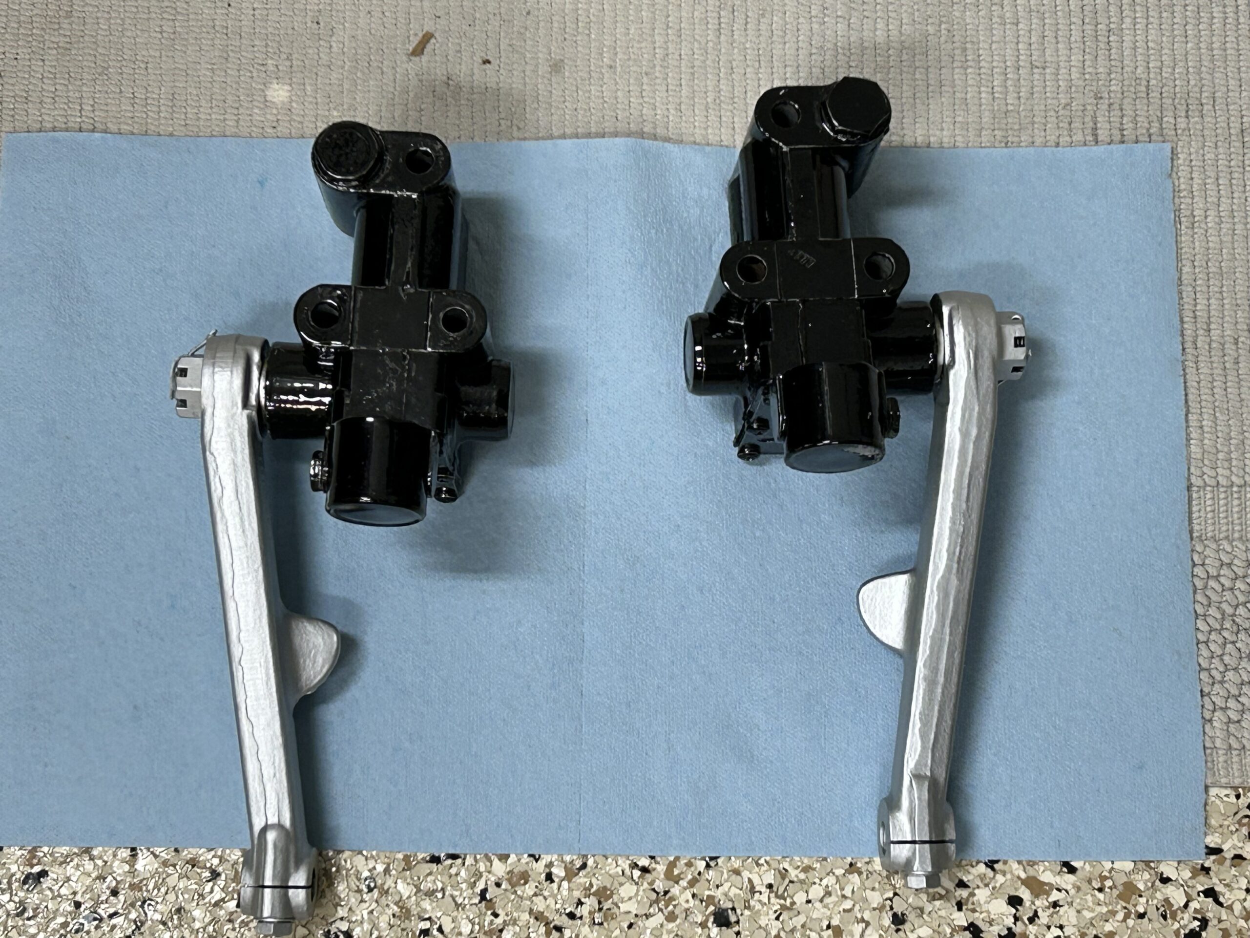
Rebuilt Front Lever Shocks
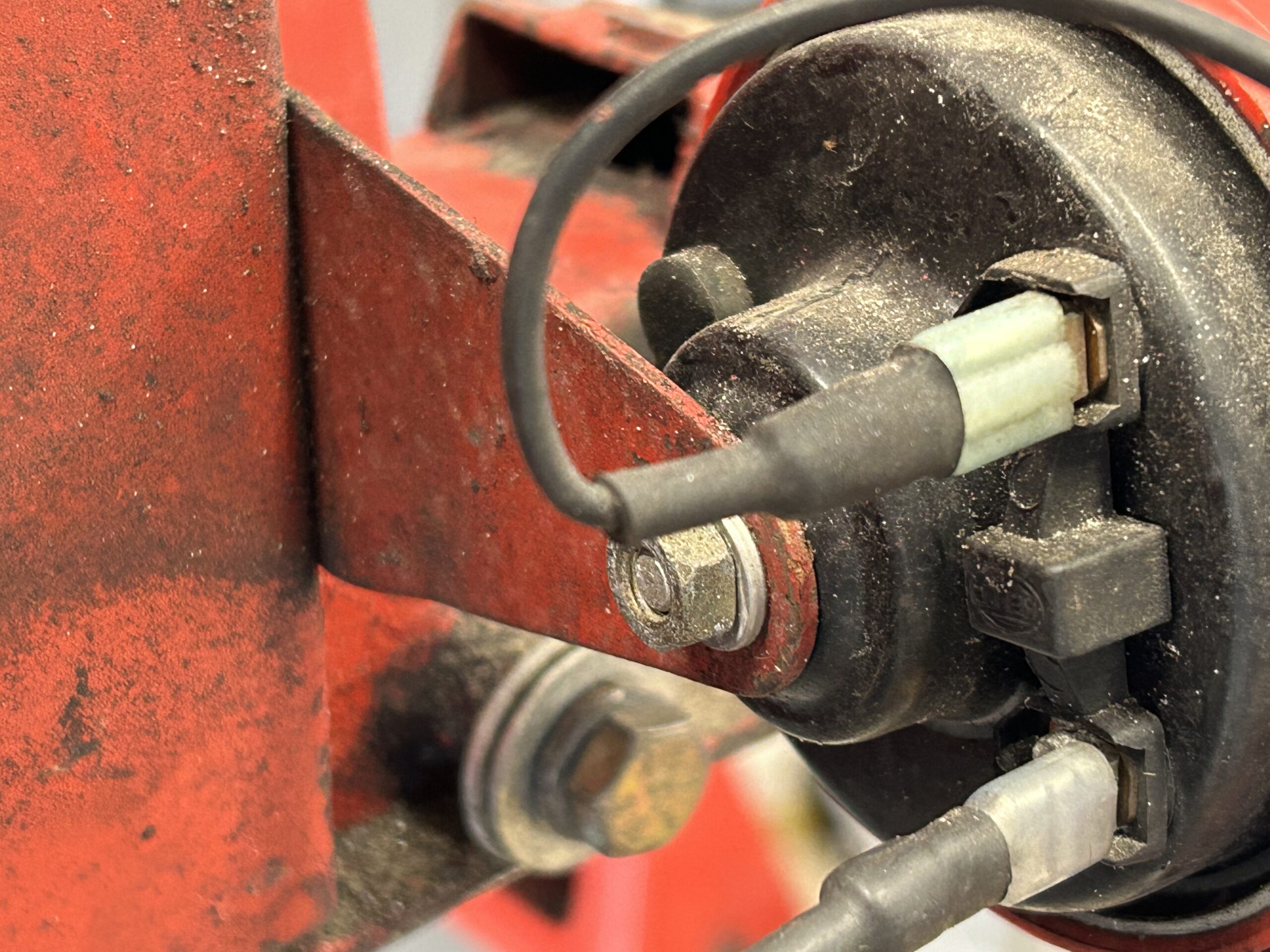
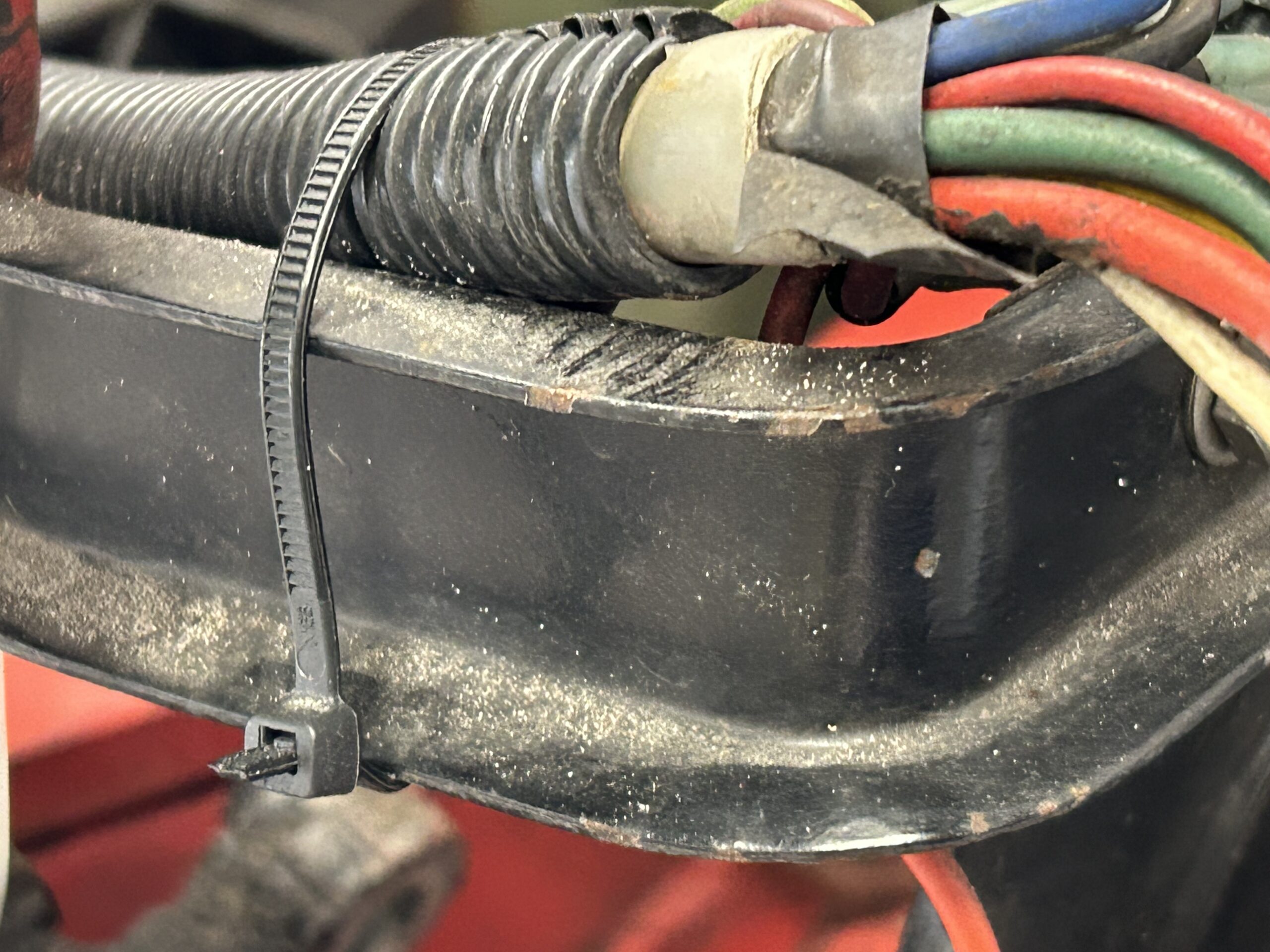
There are two wiring harnesses that run along the right inner fender valance. The smaller one is for the horn and the larger one is for the front lights and the electric radiator fan. The smaller horn harness is held in place by two “P” clips that are secured with Phillips head machine screws that are #10-32 x 1/2″ to captured nuts in the valance.
Horn wiring harness
Horn wiring harness
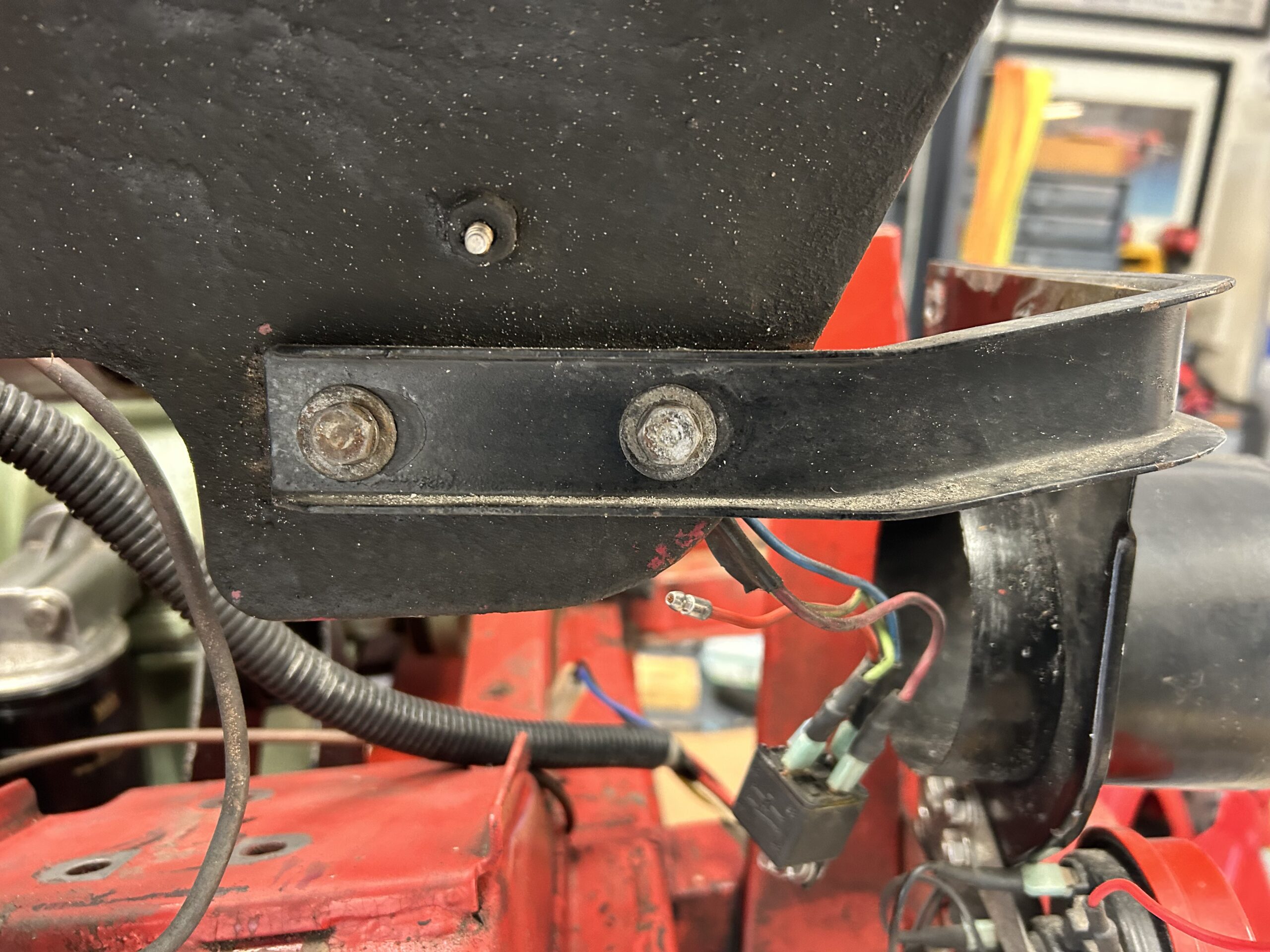
The horn harness is routed to a relay with four wires. The dark red wire is connected to relay terminal 84, the blue wire is connected to terminal 87, the green/brown wire is connected to terminal 86 and the red wire to the horns is connected to terminal 30.
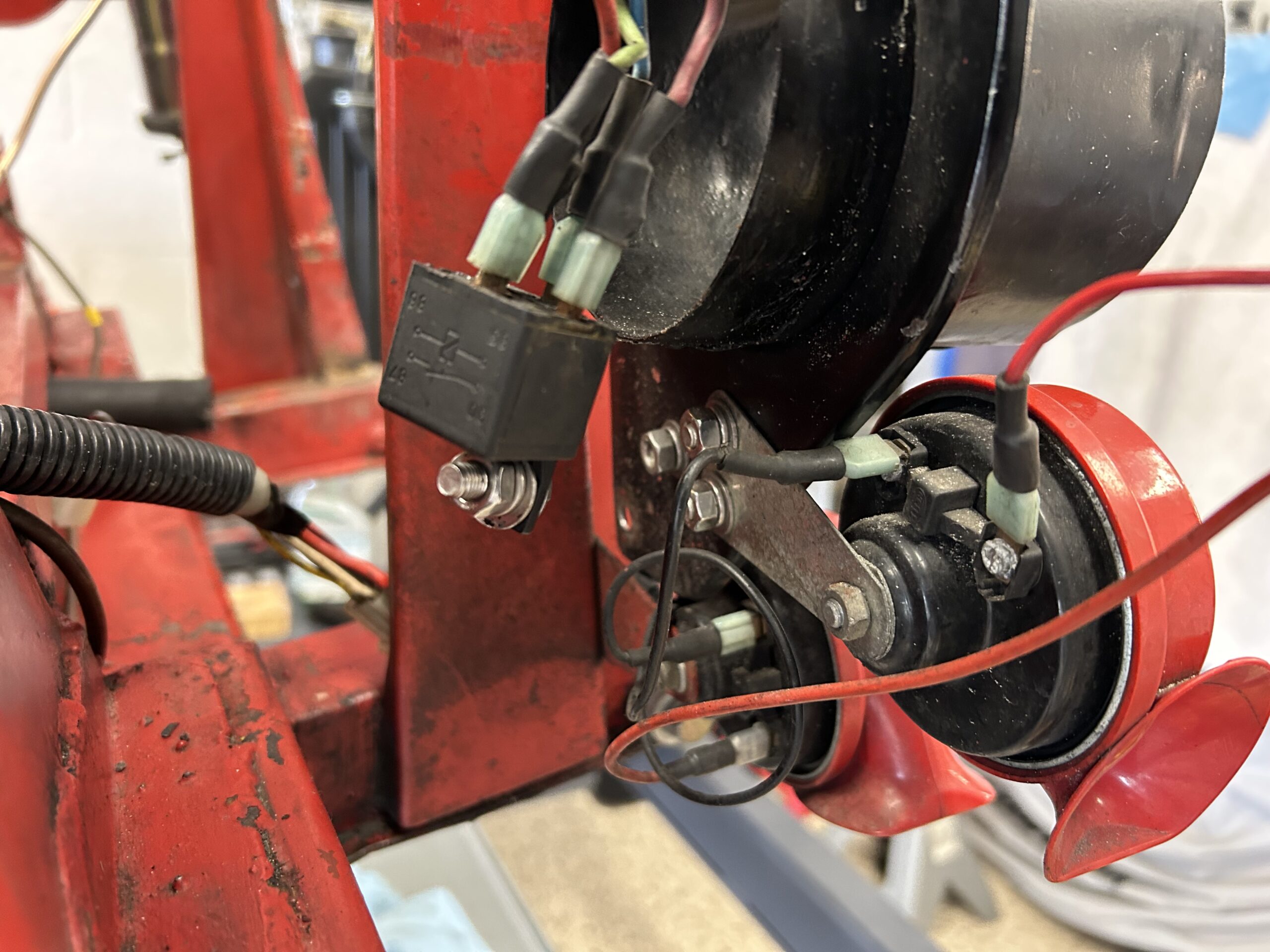
Horn Relay

Lower Horn
Horn Wiring Connections
There are two horns. The upper horn is mounted to the fresh air intake panel and the lower horn is mounted to the chassis via a bracket and two Phillips head #10-32 x 1/2″ machine screws. Power to the horns comes from the relay terminal 30 that feeds to a splitter with one red wire then routed to each horn. Each horn also has a black ground wire.
The larger lights and fan harness is zip-tied to the RH inner fender brace. The air intake is also held in place with the brace.
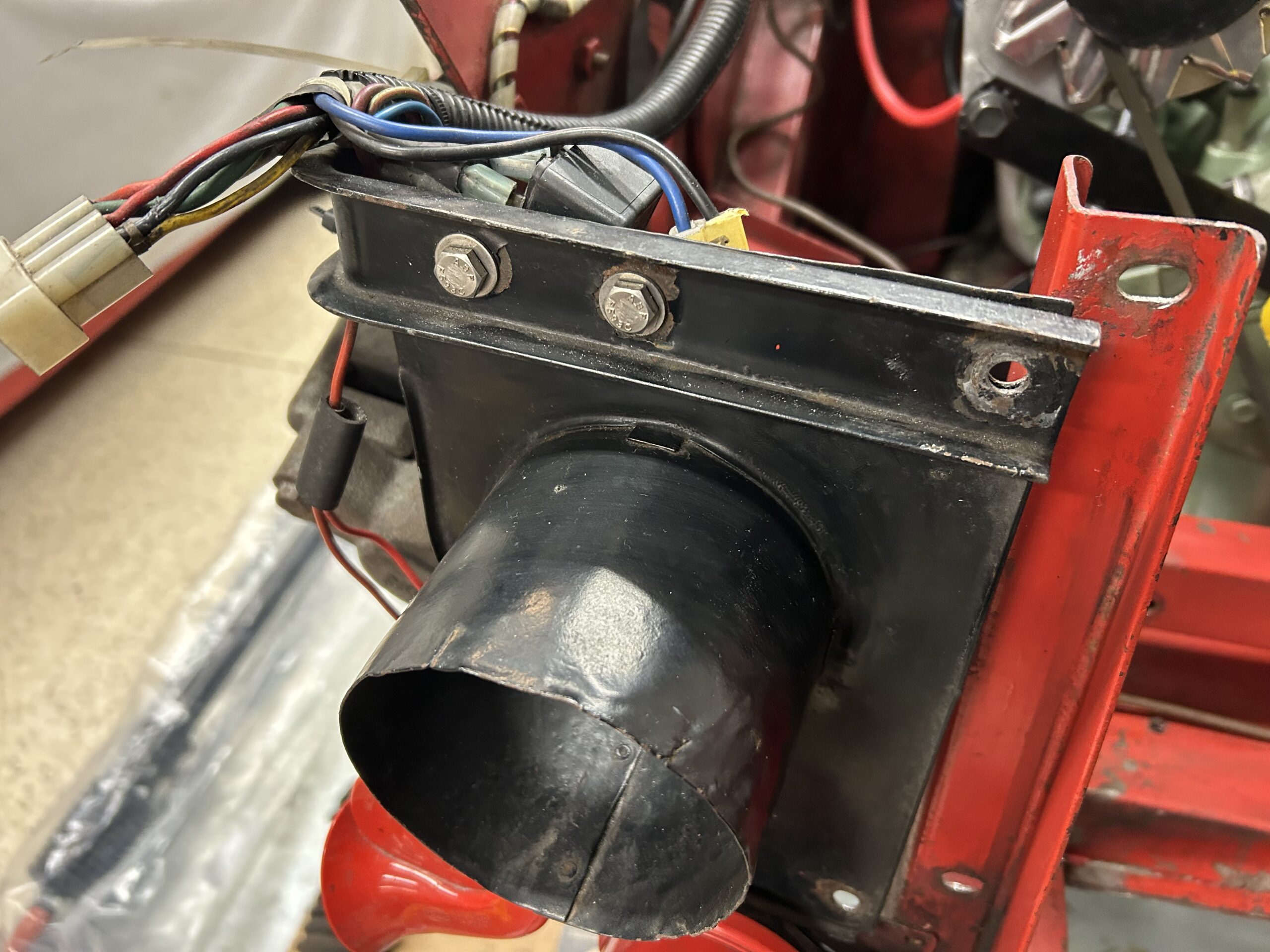
Air Intake and Inner Fender Brace
Lights and Fan wiring harness
The inner fender brace is secured to the inner fender captured nuts with 1/4″ – 28 x 5/8″ hex head bolts. The bolts were removed as was the brace.
RH Inner fender brace
Removing components and cleaning unfortunately revealed chassis damage. The left front bonnet brace extension has been bent and the LH radiator upright has been previously repaired. These items will require attention later.

Damaged Chassis Bonnet Extension
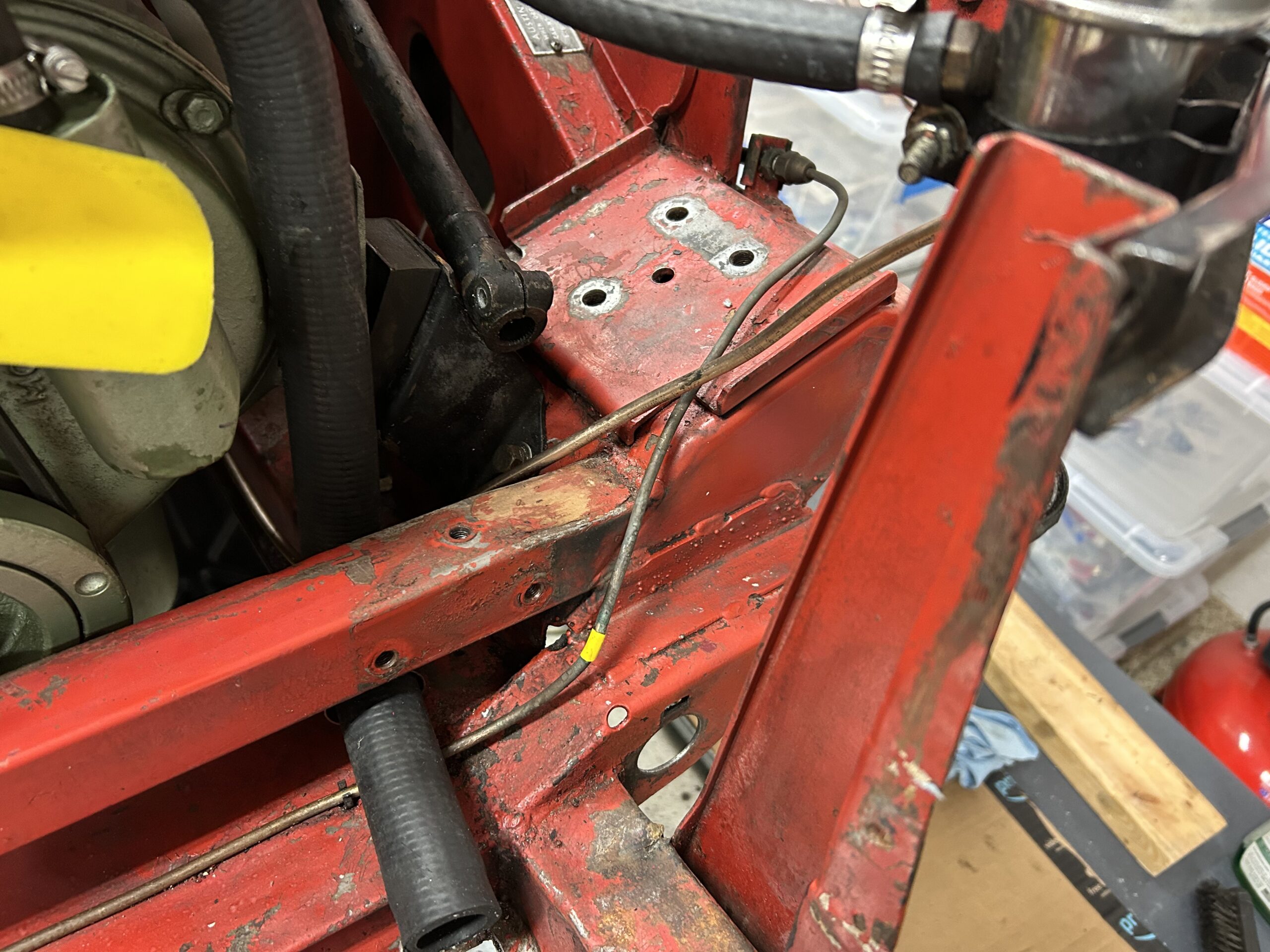
Damaged Radiator Mount Upright
Previous Upright Damage Repair