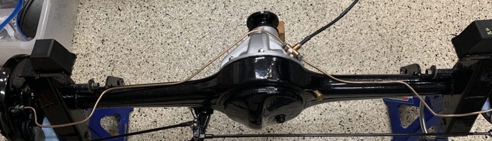
Since the last entry, the axle was painted with POR-15. The preassembled MG Midget brake assemblies were mounted to the axle and rotated to be in the proper position to align with the handbrake rods. Initially they were installed in the wrong orientation. The 3.9 differential was installed in the axle as well as the new cunifer brake pipes. The brake pipe union was cleaned and polished. A new Goodridge black stainless brake hose was connected to the union using a new copper crush washer.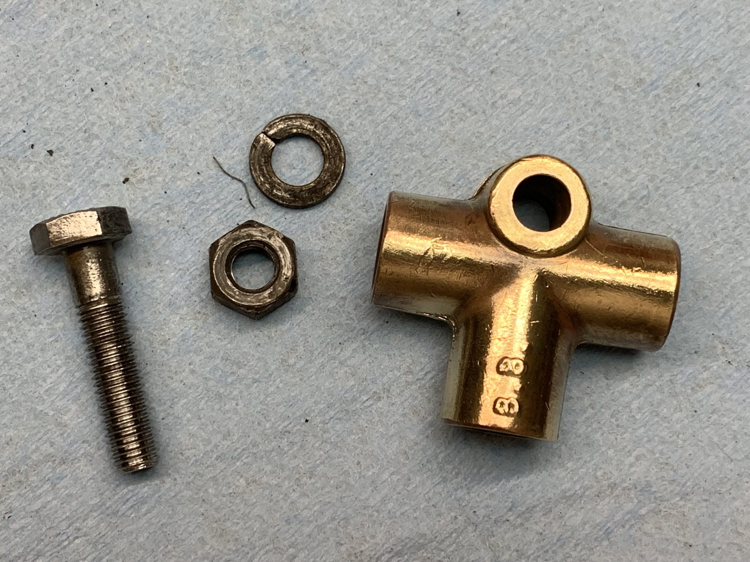
A new brass Land Rover axle breather was purchased and installed on the axle. The MiniMania adjustable handbrake rods were painted and connected to the brake levers and the compensator lever with new clevis pins and felt anti-rattle washers. Finally, the rubber rebound buffers were attached to the axle with the ends of the split pins facing to the front of the car and rubber caps were placed on the bleeders. All of this work is shown in video Episode Nine.
https://vimeo.com/769593182/8c2f05ffc9
Installing the hubs turned out to be a much more challenging job than expected. Based on what others had shared we were under the impression that swapping the original brake assemblies for the later Midget brake assemblies was a plug-and-play process. At least in our case, it was not! As can be seen in the next video, the flange on the Midget back plate stood higher than that on the Bugeye original backplate. This meant that as the Hub was pressed down until it was seated, it was fouling against the backplate flange making it almost impossible to turn. Video Episode Ten shows the problem we faced.
When the Sprite Forum members were queried about this problem, others did mention the possibility of this problem. It was suggested that the flange should simply be trimmed about an 1/8″ so that the hub would not contact it when pressed down fully. So, we got out the Dremel and did just that. Fortunately, that solved that problem.
New hub bearings were installed. This video, Episode Eleven, shows the full process. Timken 207FF bearings were used.
https://vimeo.com/769633649/bd8bbee949
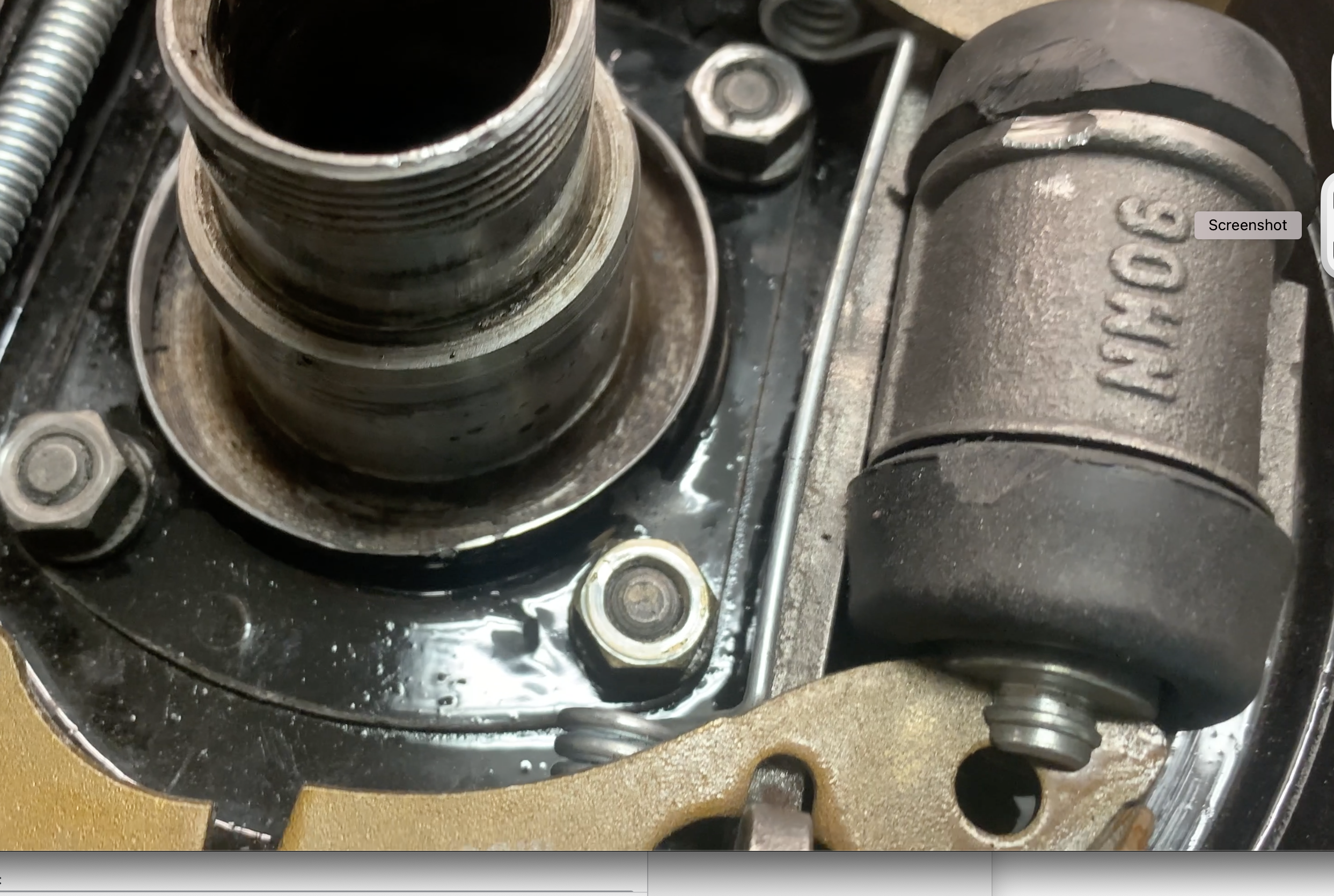
Following installation of the hubs, I noticed that one of them was still encountering some resistance in rotating. Turned out the the raised portion of the hub where the studs are located was ever so slightly touching one edge of the brake cylinder. While I was not happy with my solution, it did solve the problem. This can be seen in video Episode Twelve.
https://vimeo.com/769896299/f92cfe0068
Brake Cylinder Relieved
True to form, when we installed the brake drums on to the hubs we once again encountered resistance to turning! This easy swap to later rear brakes has not been without its challenges. Sure enough, after checking with others on the Sprite Forum it turned out that people did often have to grind down the outside edge of the drums to get them to fit without fouling against the backplate. Whether this is an issue with drum manufacturing tolerances or some other issue – we just don’t know. So, out came the angle grinder with a cut off wheel and we cut some of the drum away and smoothed the edges as best we could. Once again, we aren’t happy with the approach, but also once again, it solved the problem. Everything now rotates freely. The video Episode Twelve shows the process.
https://vimeo.com/769904083/75a1d4a732
After addressing the relocation of the fuel pump from the engine bay to the bulkhead behind the passenger compartment, the installation of a new fuel tank and new fuel pipe, the installation of new rear leaf springs and the cleaning and painting of other rear suspension components, we will return to the installation of the completed axle in the car.
Stop it!
Hah! I can’t. Your little Bugeye magically draws me into the garage saying “make me pretty, make me pretty”