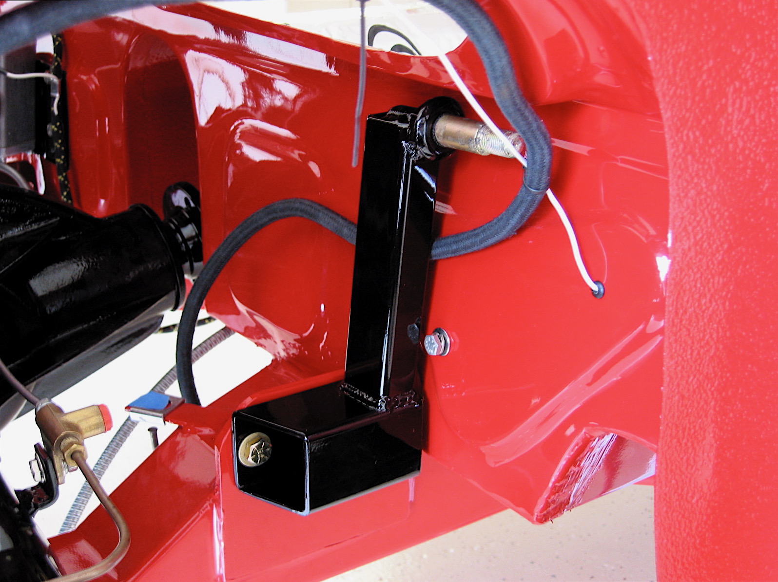
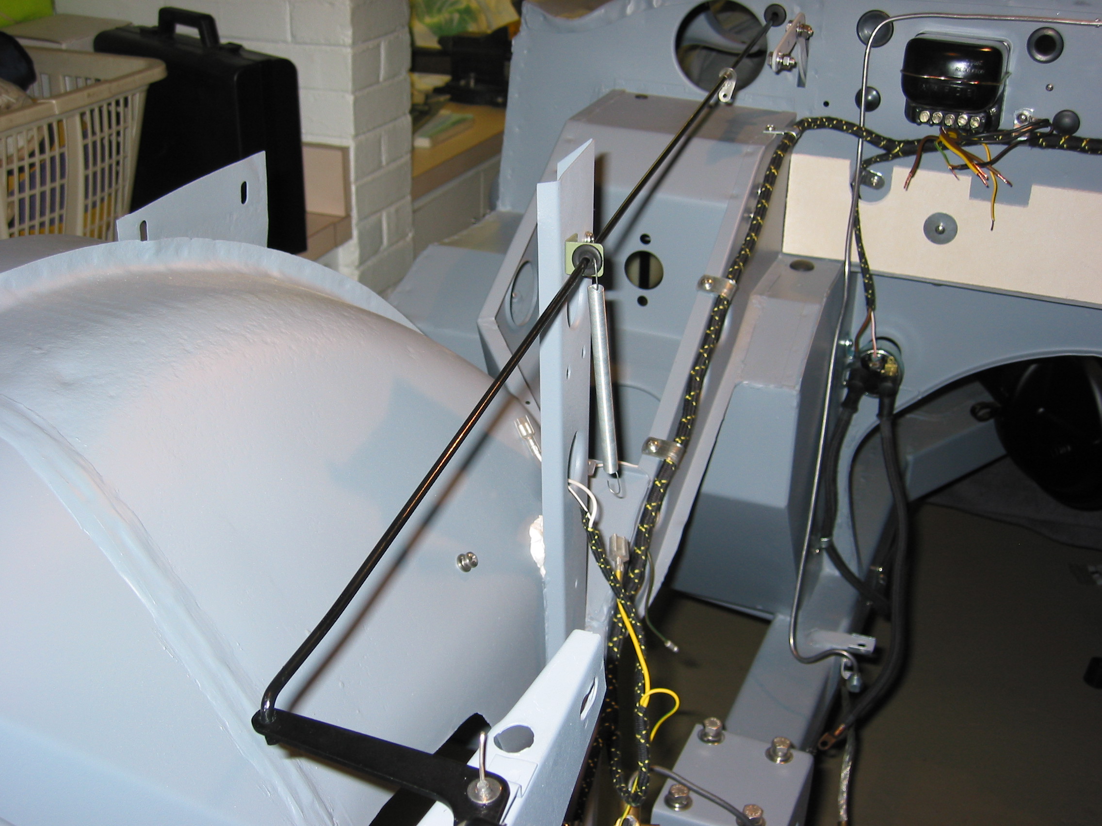
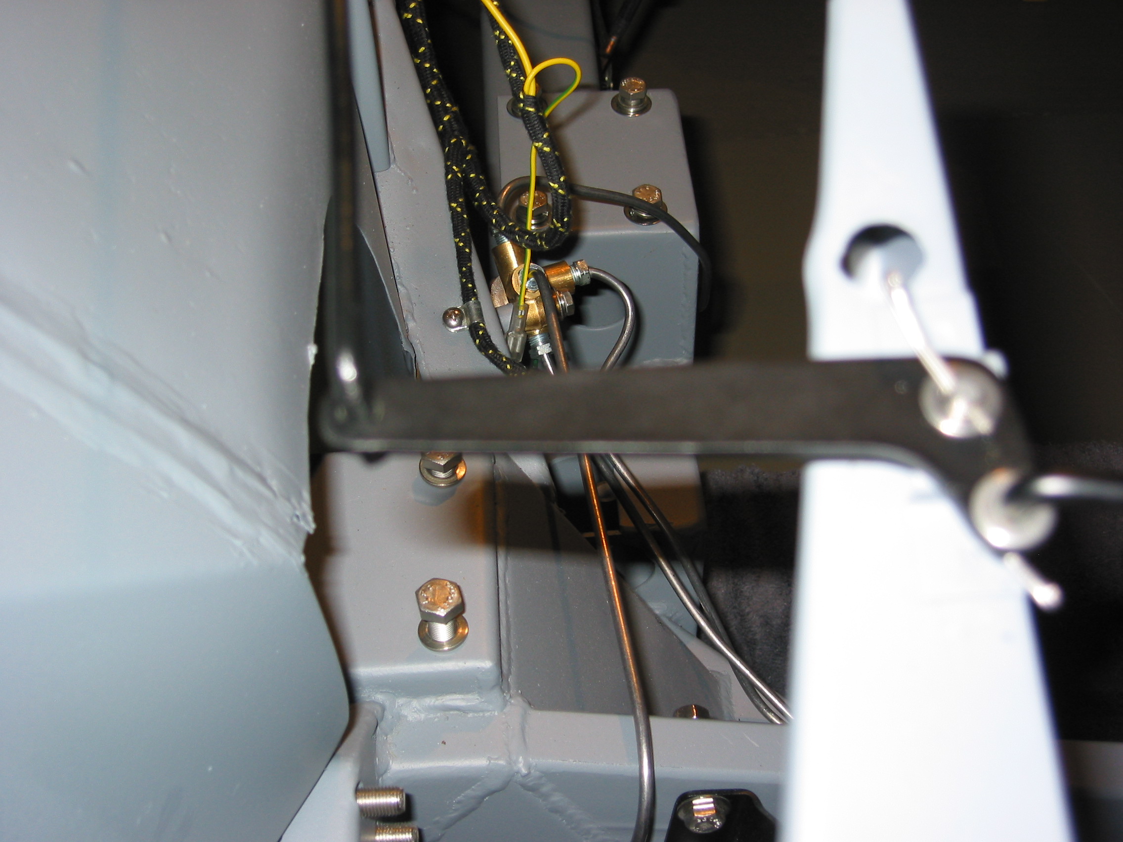
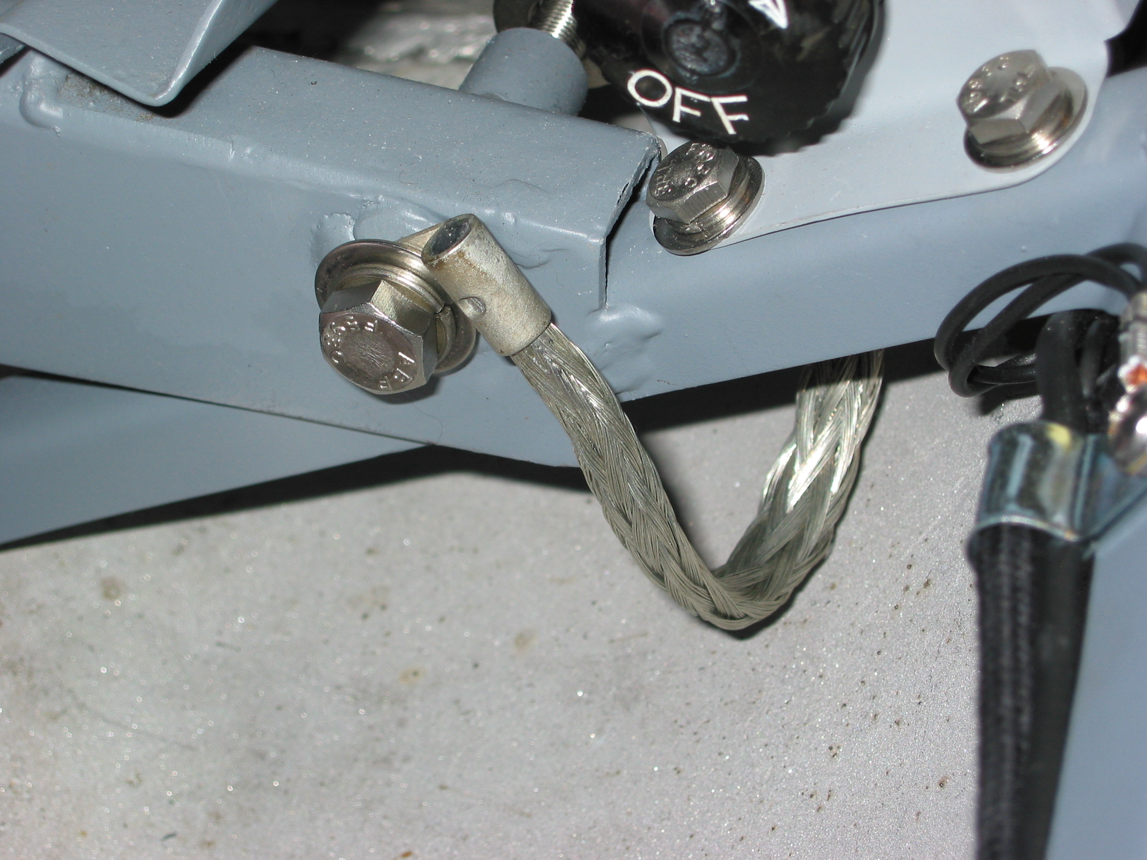
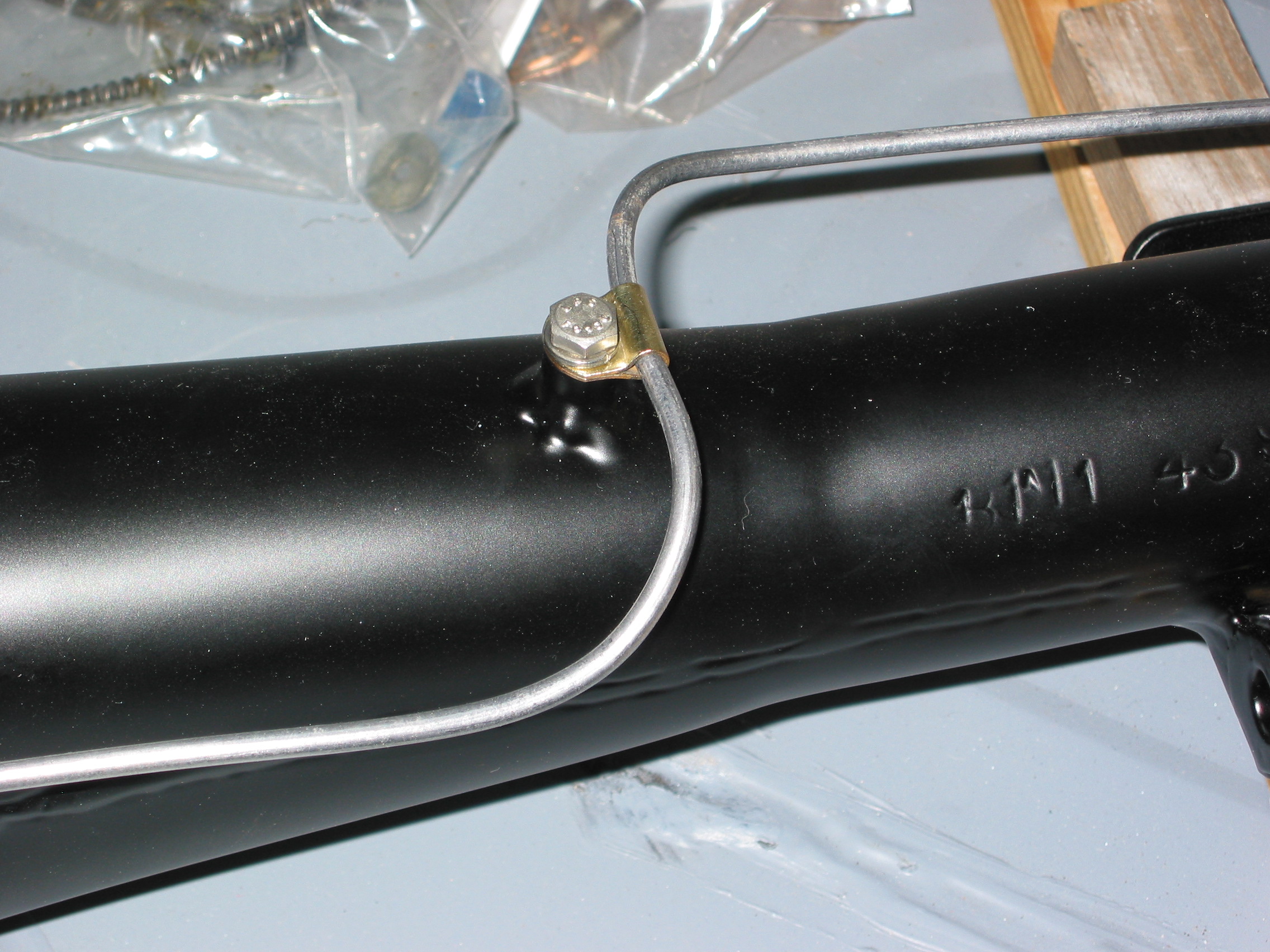
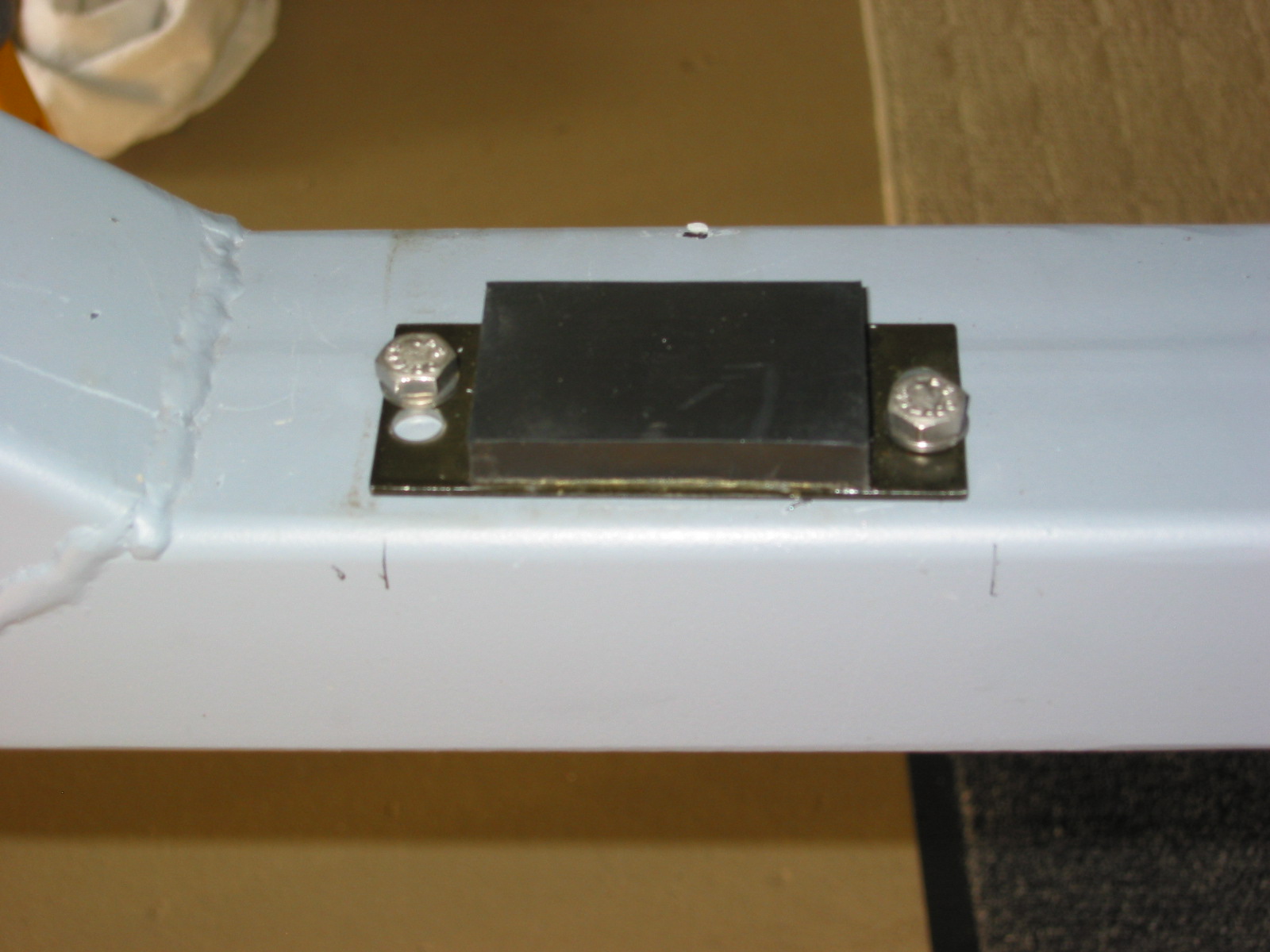
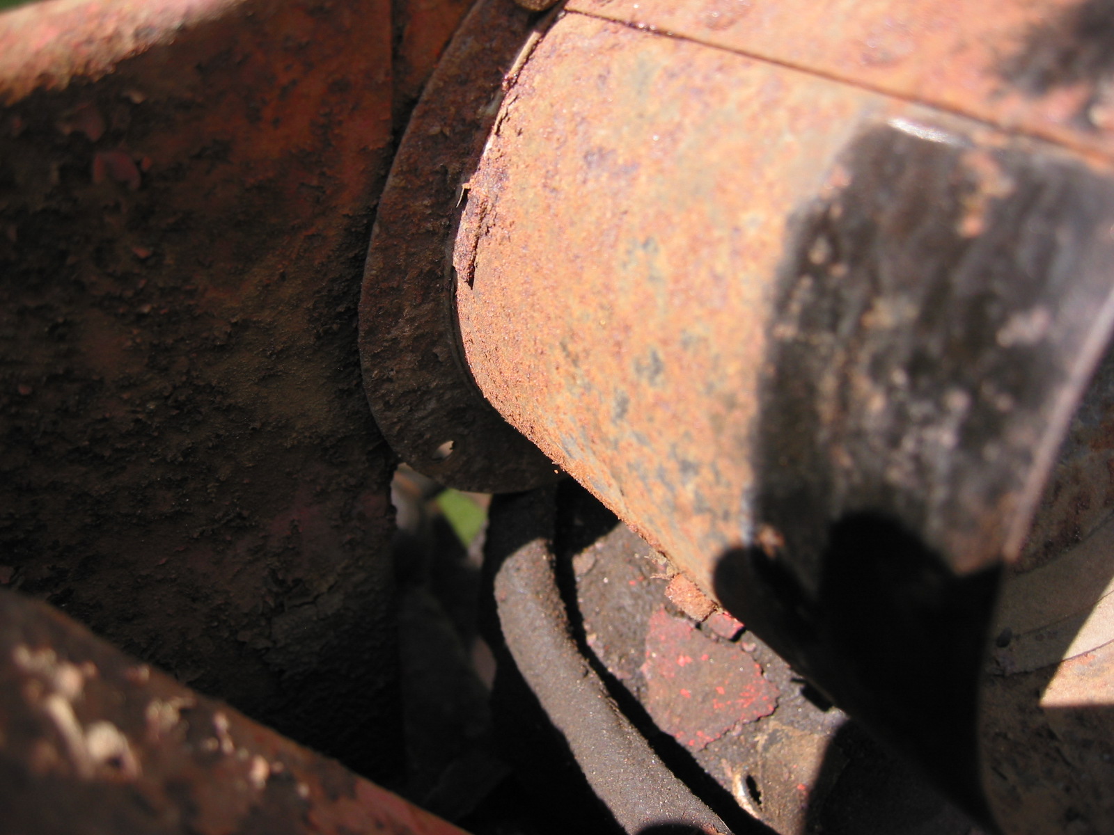
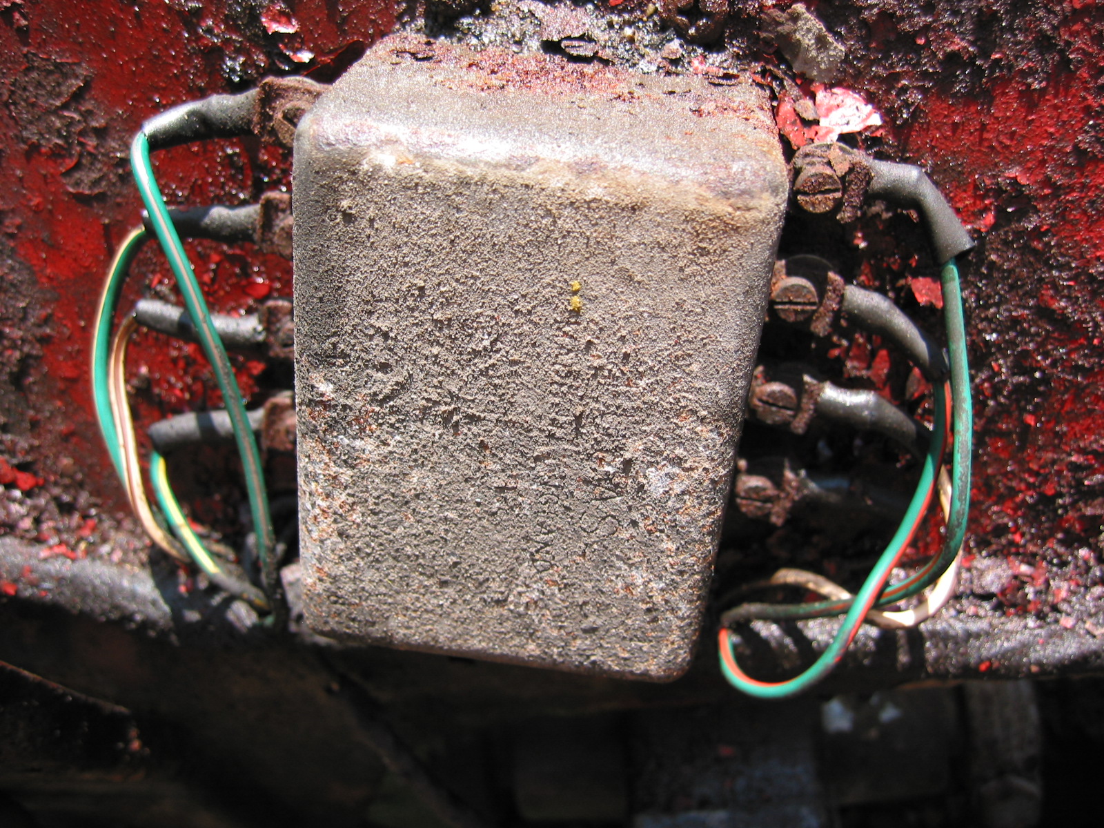
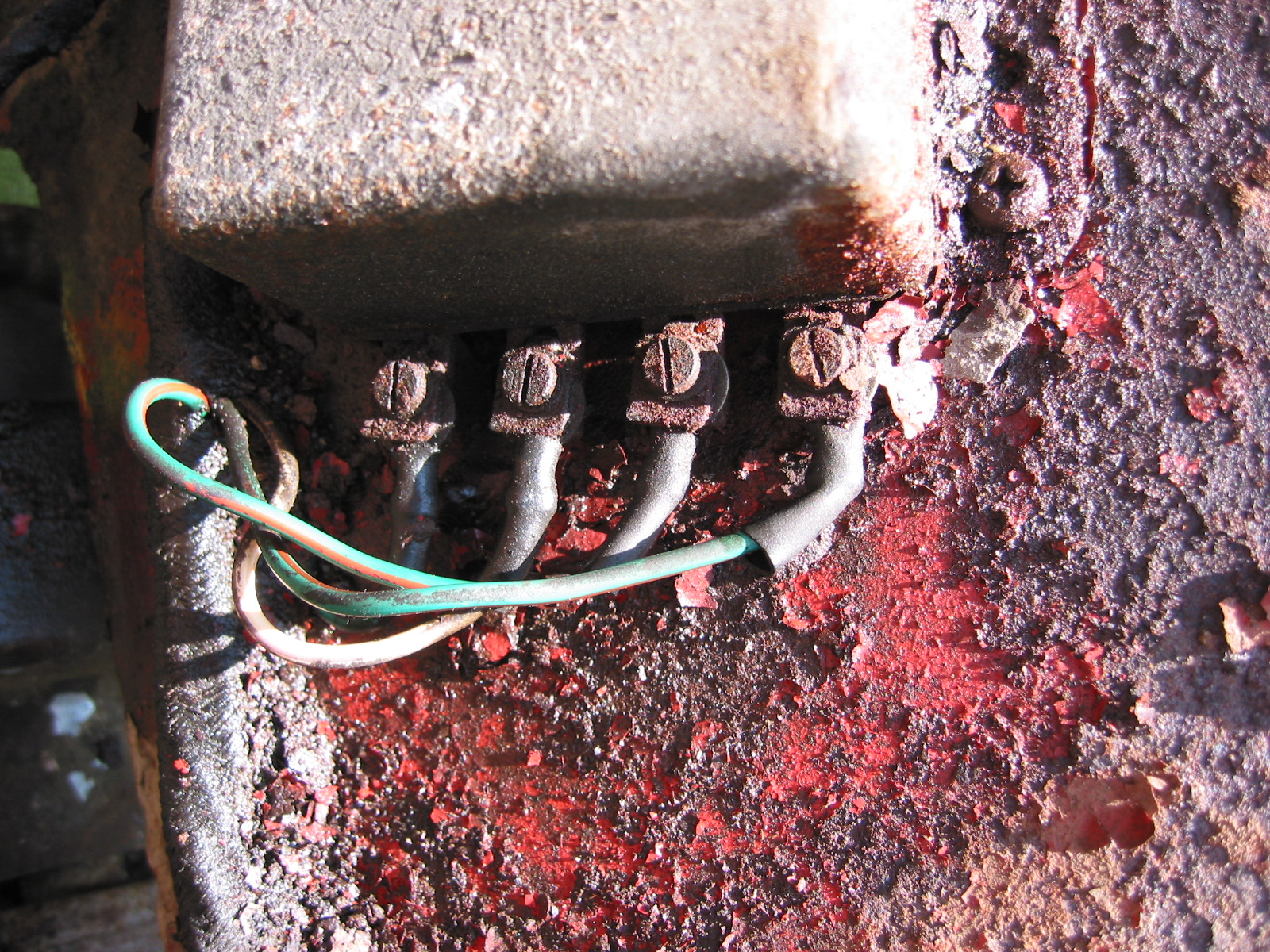
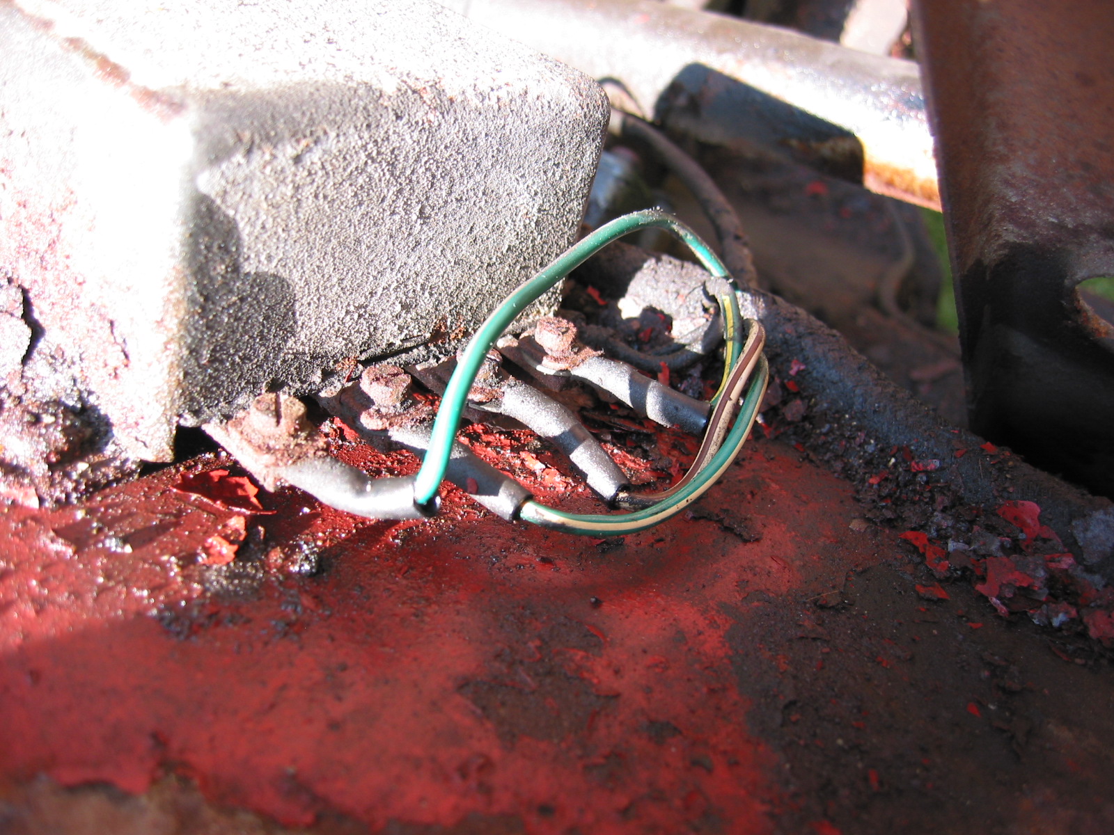
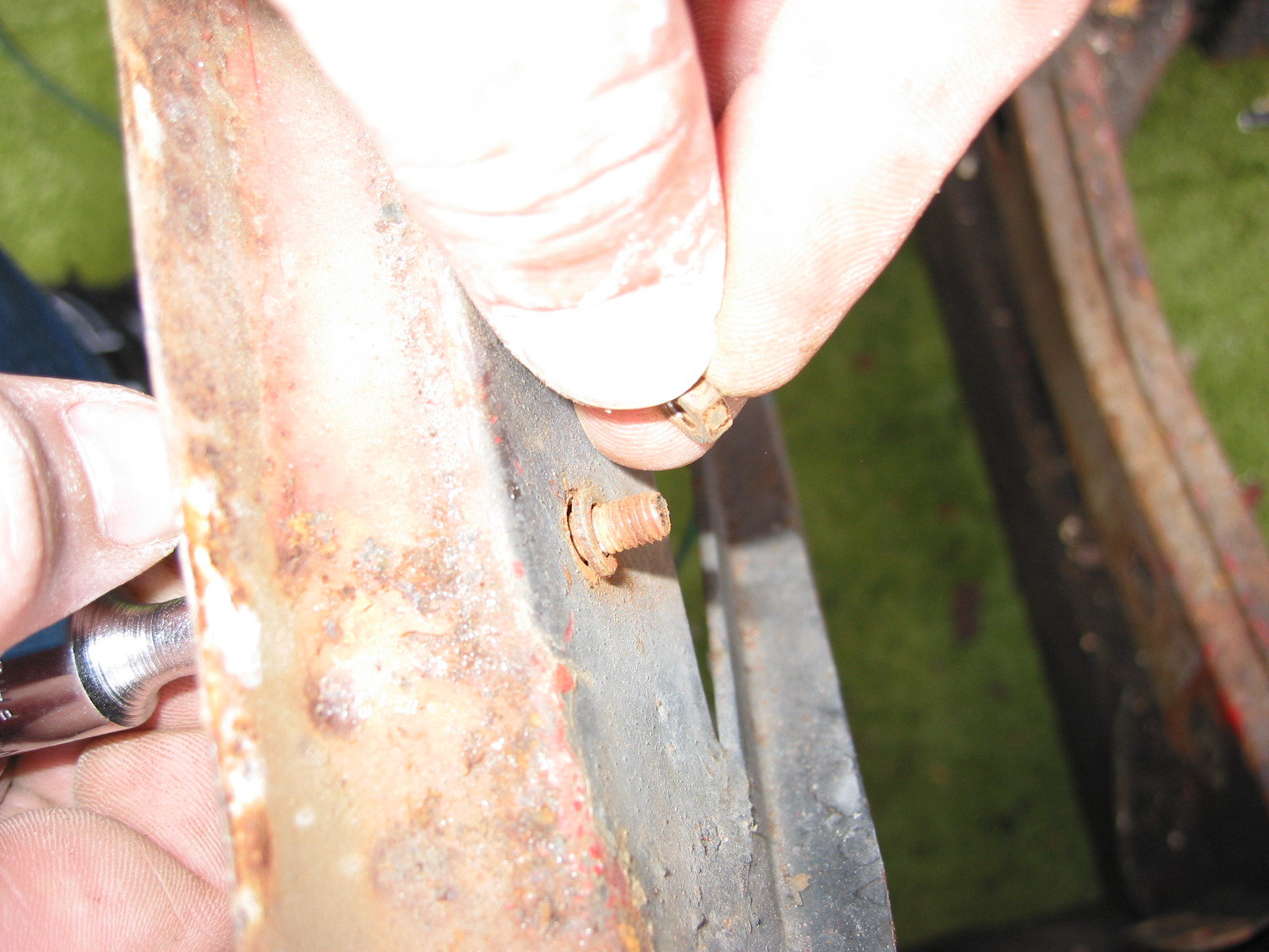
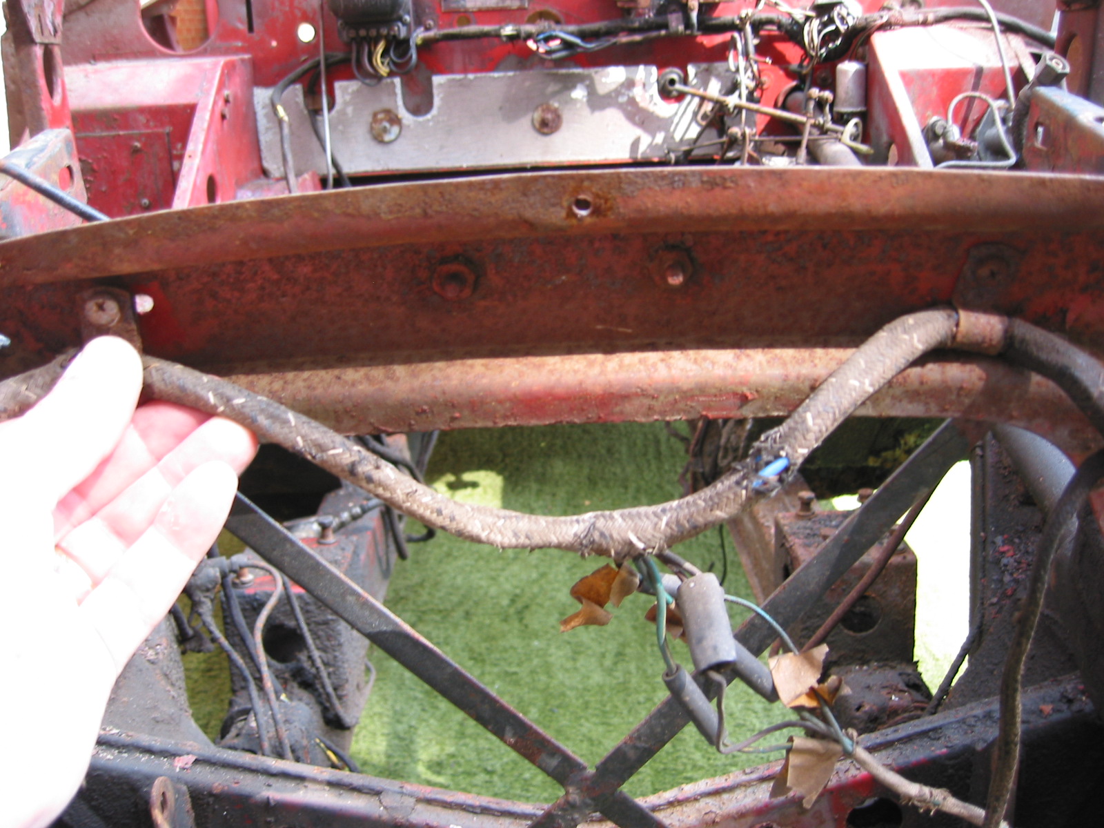
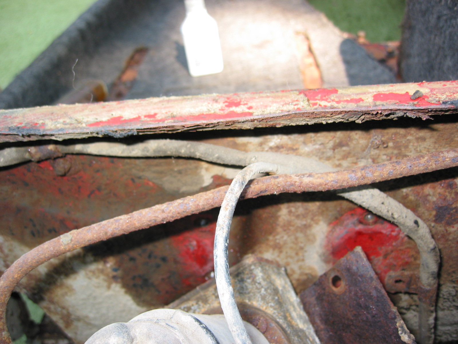
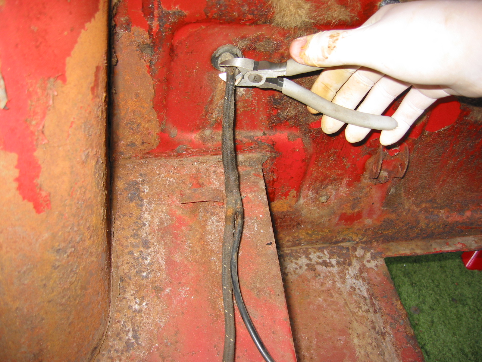
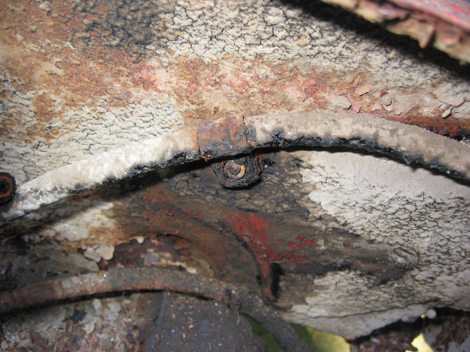
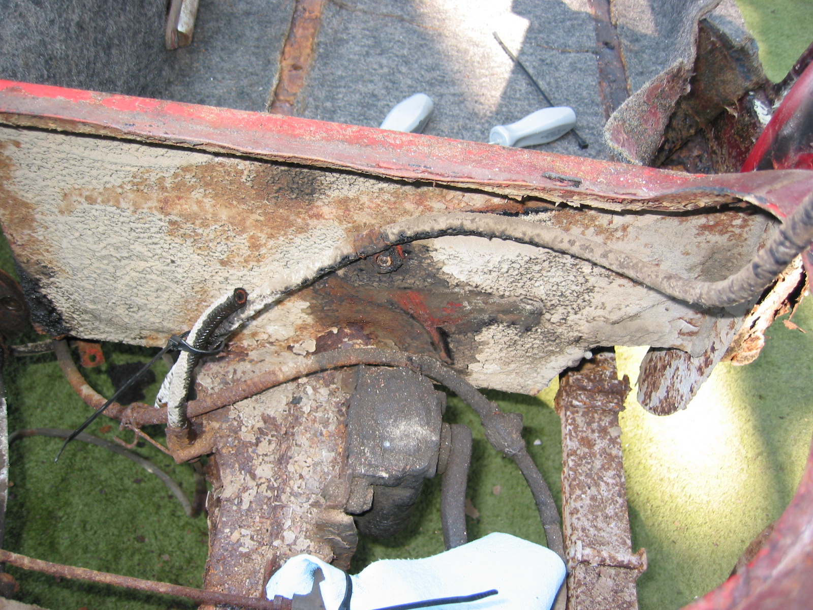
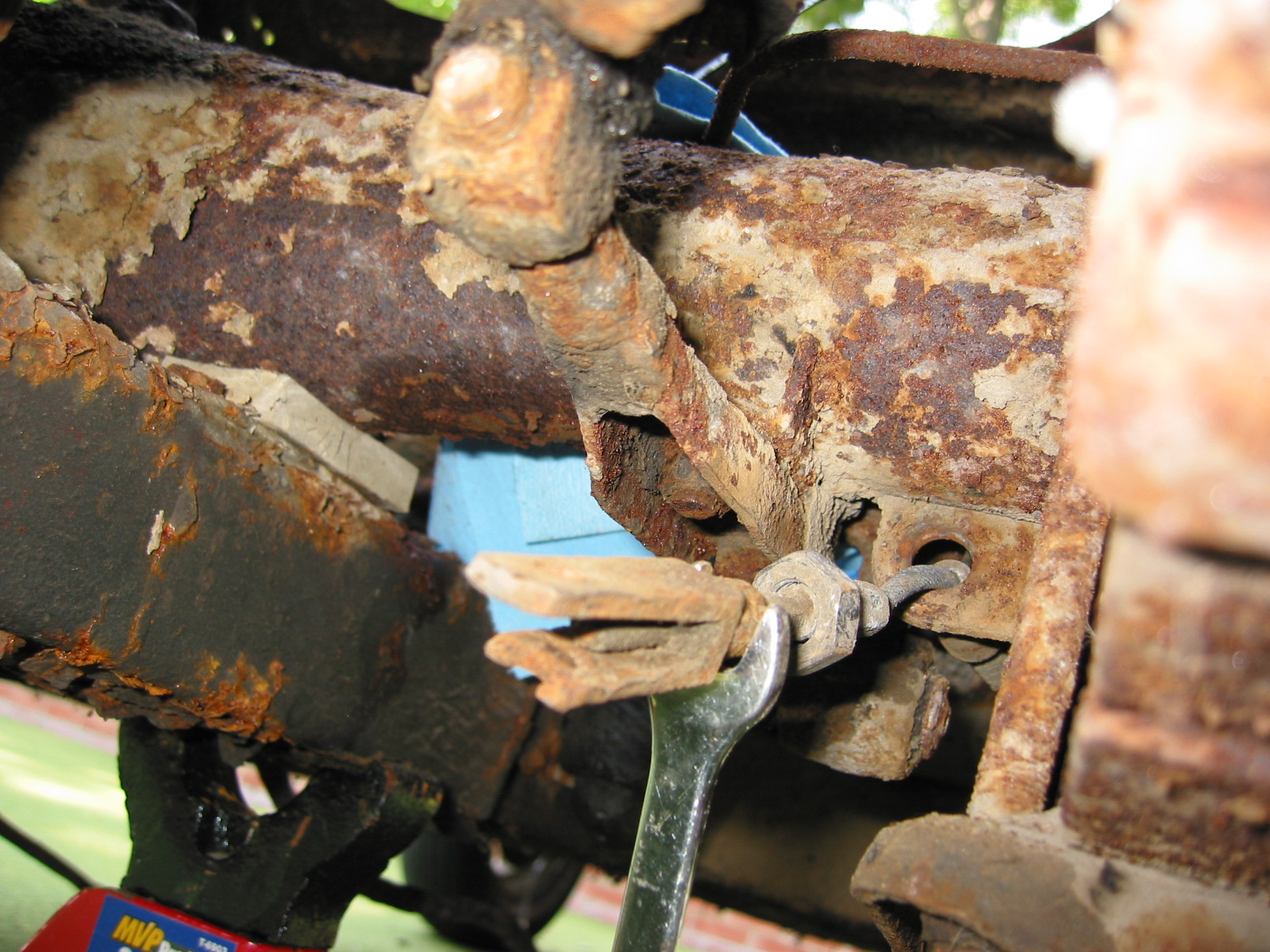
The Battery Cable – from engine to boot. Eight to nine clips attached with screws to frame.
October 20, 2002
Shipping to Jule Enterprises
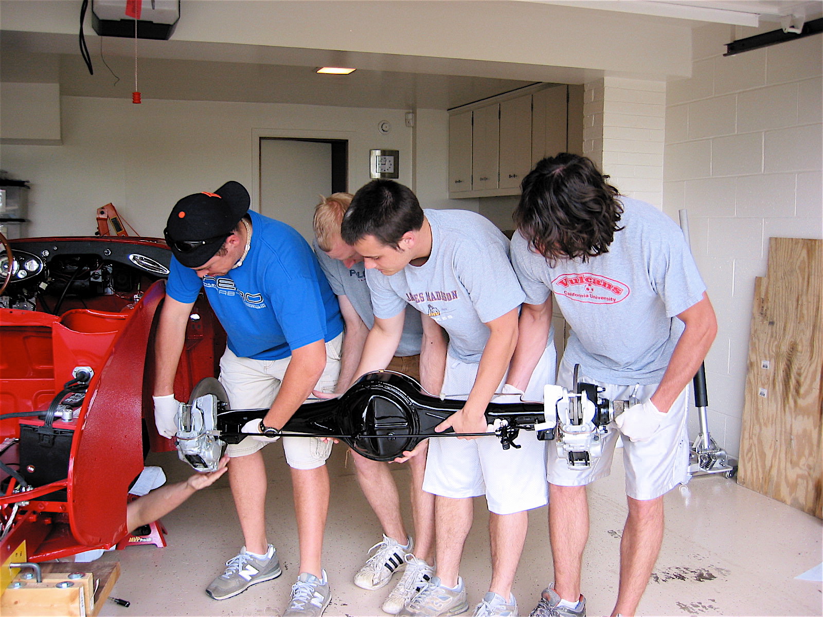
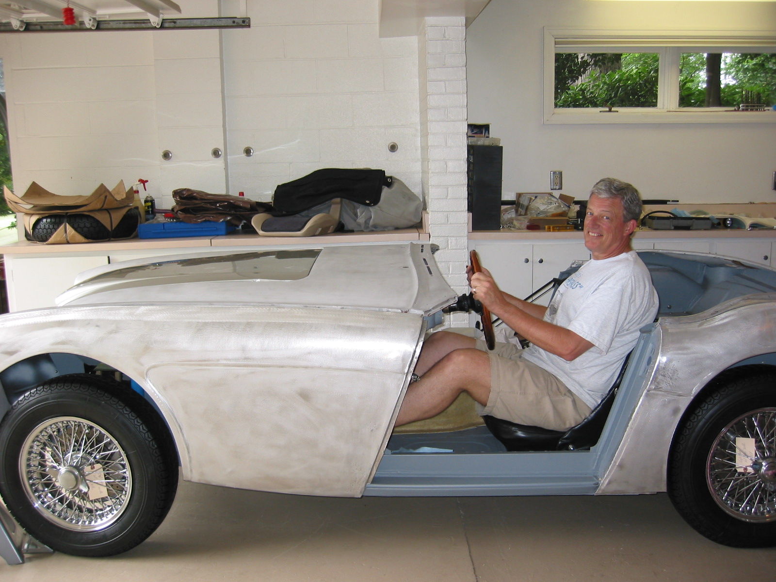
Martin Jansen – from Jule Enterprises located just outside of Toronto picked up the car for the trip back to Canada for frame replacement and restoration. John, Scott and I had visited his shop in Canada earlier in the summer to “check it out.” We were pleased with what we found and I arranged for Martin to pick up 4422 for restoration work.
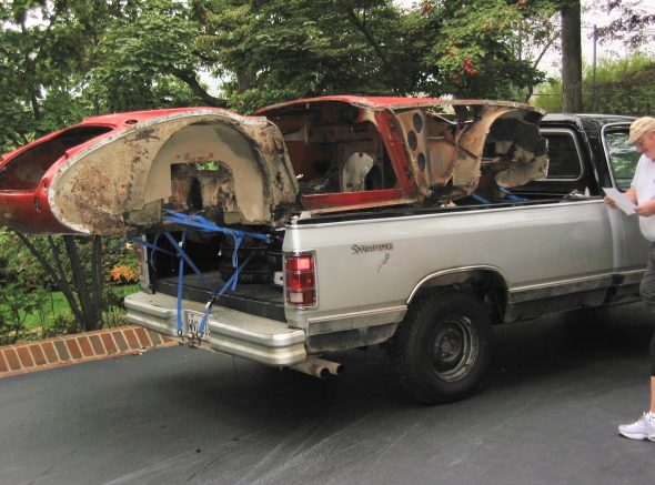
Martin Jansen Picking Up the Healey 10-20-2002
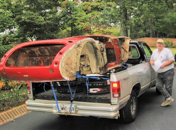
Martin Jansen Picking up the Healey 10-20-2002 2
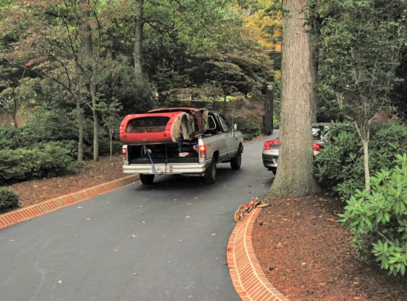
Martin Jansen Picking up the Healey 10-20-2002 3
Martin returned to Canada with the primed doors and four new aluminum wings to be fitted before bringing the BT7 back to Harrisonburg. In addition to fitting the old tub to the new Jule frame, he will media blast the body, epoxy primer the car, add new aluminum flanges to the rear shroud, and do rough repairs to shroud damage on the front and left rear. We anticipate a return date around the first of February. Lots of parts to clean between now and then.
November 9, 2002
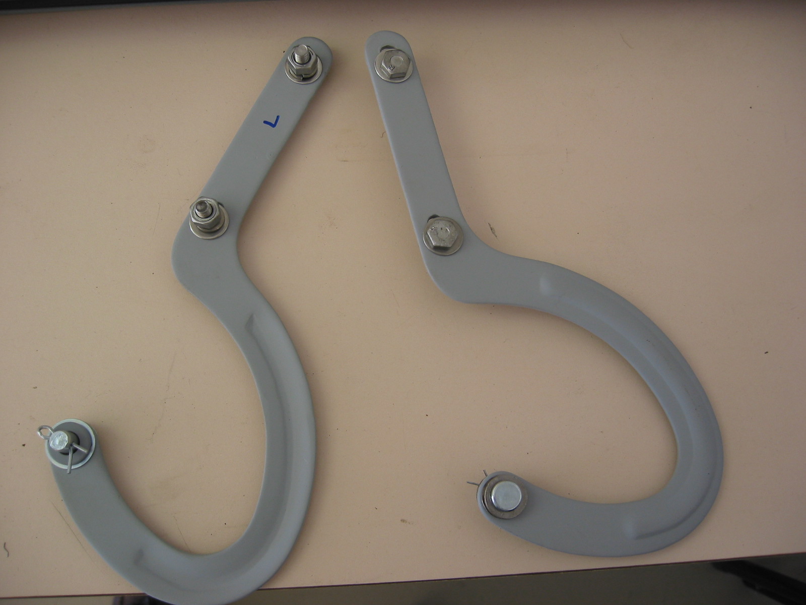
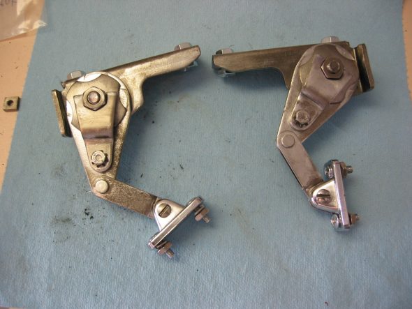
Bonnet Hinges – After a very busy work month, this weekend provided some time to return to parts clean-up and restoration. Cleaned a primed both bonnet hinges and added stainless hardware.
Cleaned and primed Bonnet Hinges
Door Check Strap Assembly – Both door strap catches were cleaned. The Moment-Anderson Restoration Book states that these straps have a zinc plated finish rather than paint. The straps will need to be refinished at a later date and new washers added.
Cleaned Door Catches
November 17, 2002
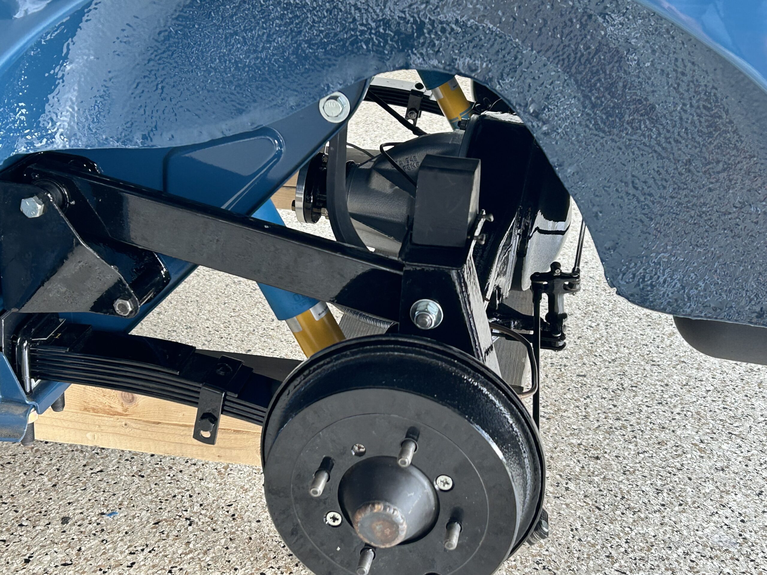
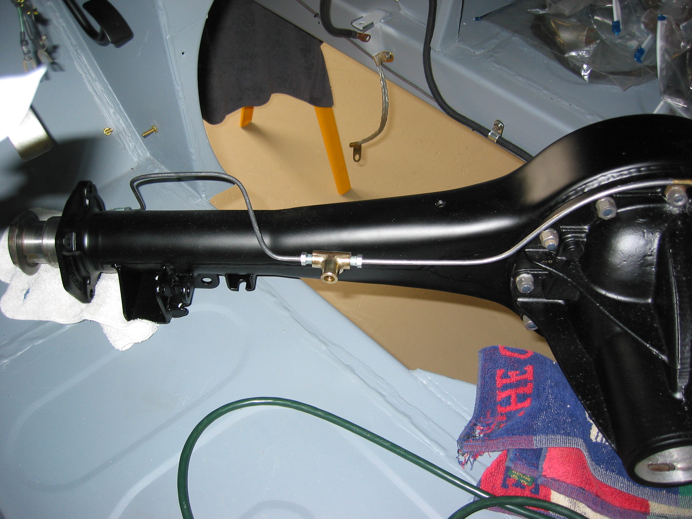
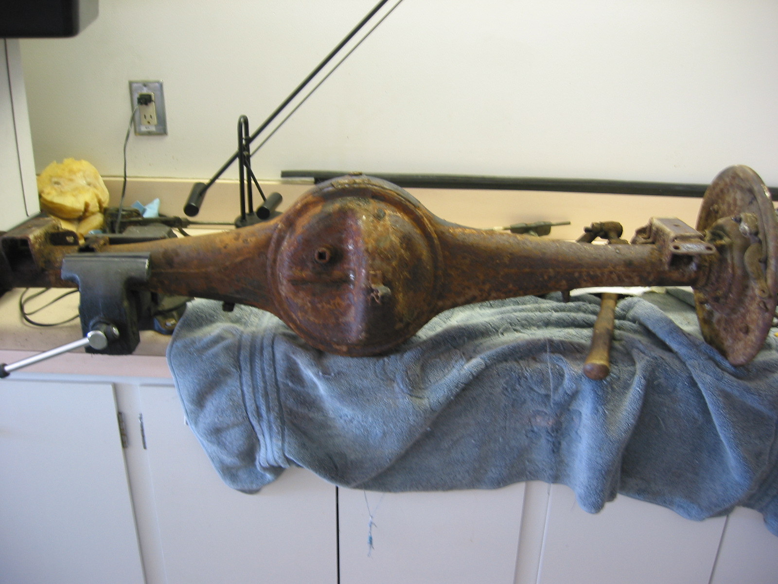
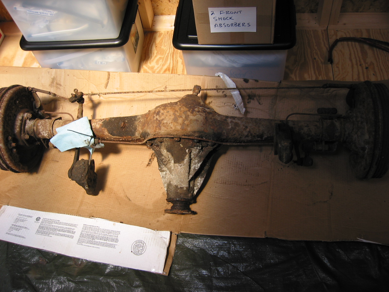
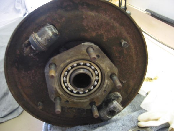
Rear Axle
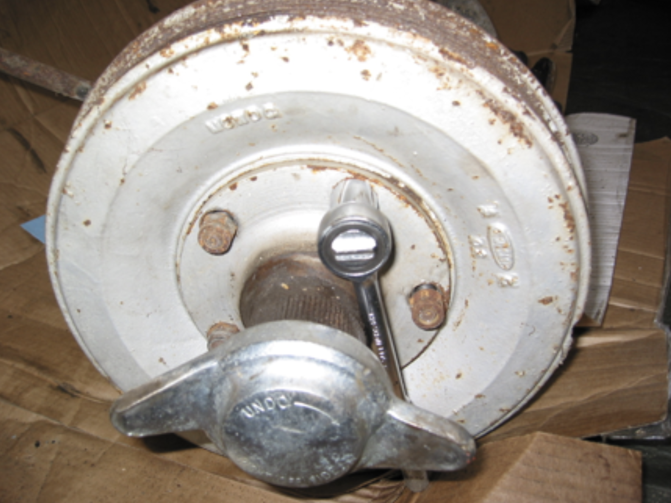
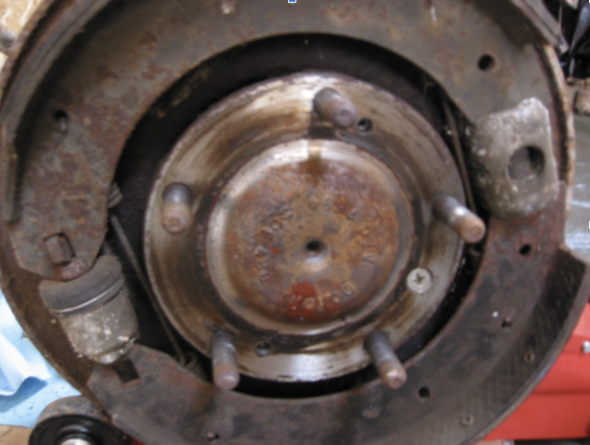
Rear axle disassembly – Removed five lug nuts and the rear splined hub. Then loosen two Phillips head screws securing the rear brake drum and remove the drum.

Brake Drum Hub Nuts
Rear Axle Half Shaft
Removed the brake shoe retaining springs and slipped off the lower shoe. Disconnected the handbrake tension spring to release pressure and slipped off the upper shoe.
Removed the shoe adjuster by loosening two 9/16” nuts and knocked out. Note shape of pistons. Remove axle by loosening one 3/8” flat head phillips screw. Note paper gasket. Pull out axle half shaft. The left and right shafts are marked with an engraved “R” or “L,” because they need to be replaced to the original locations.
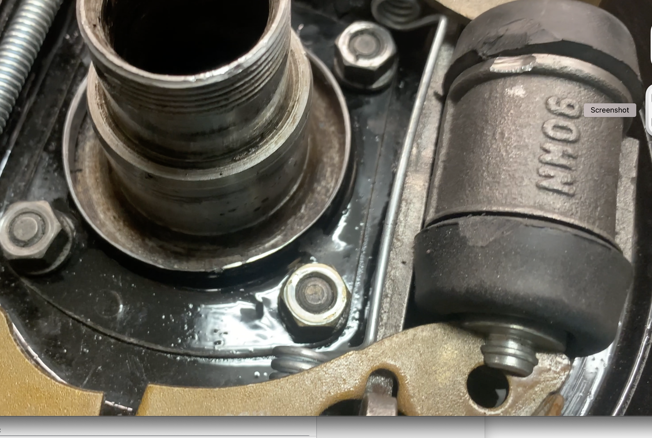
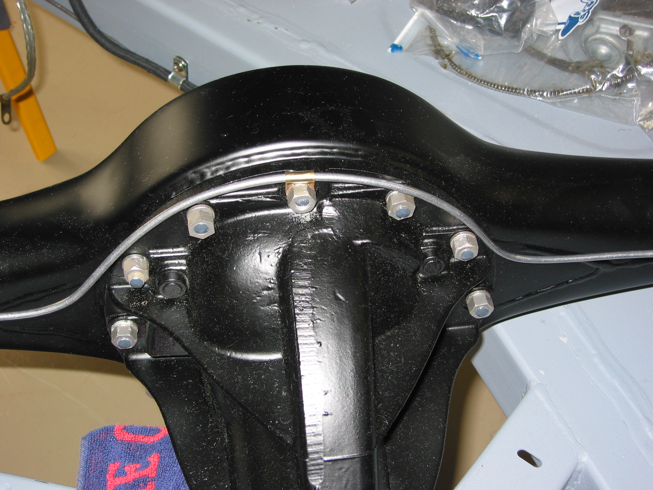
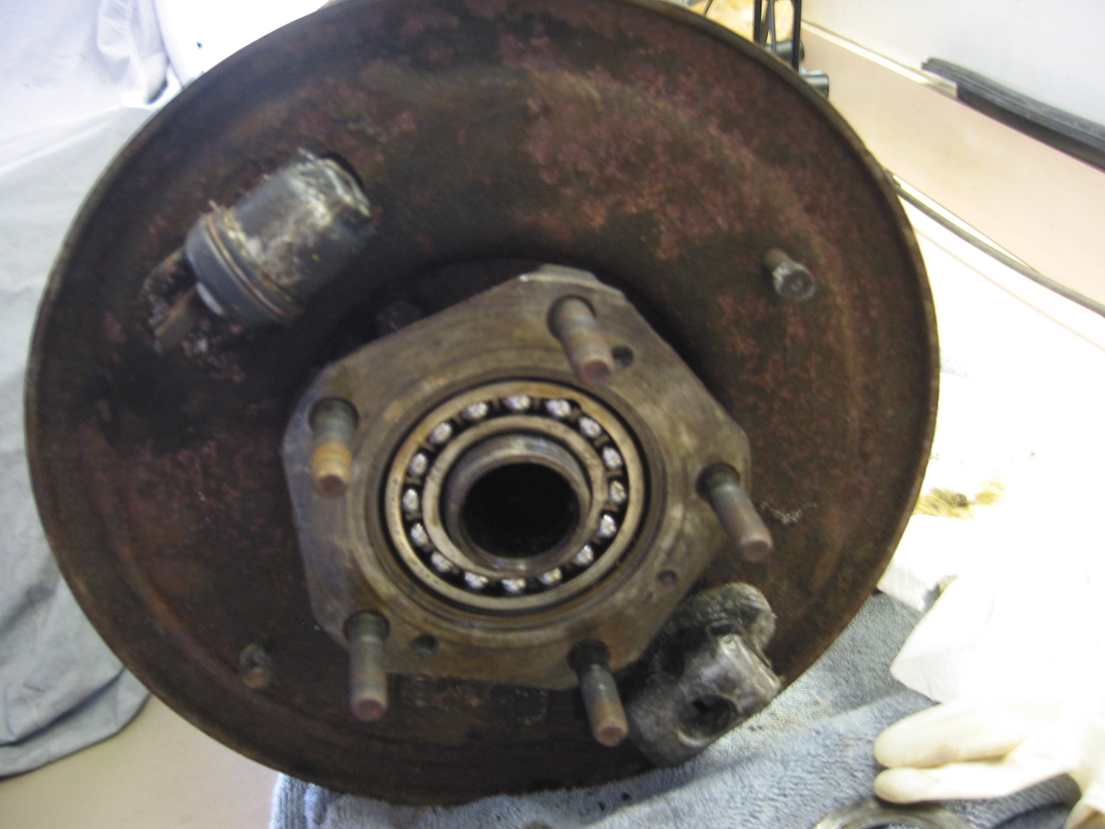
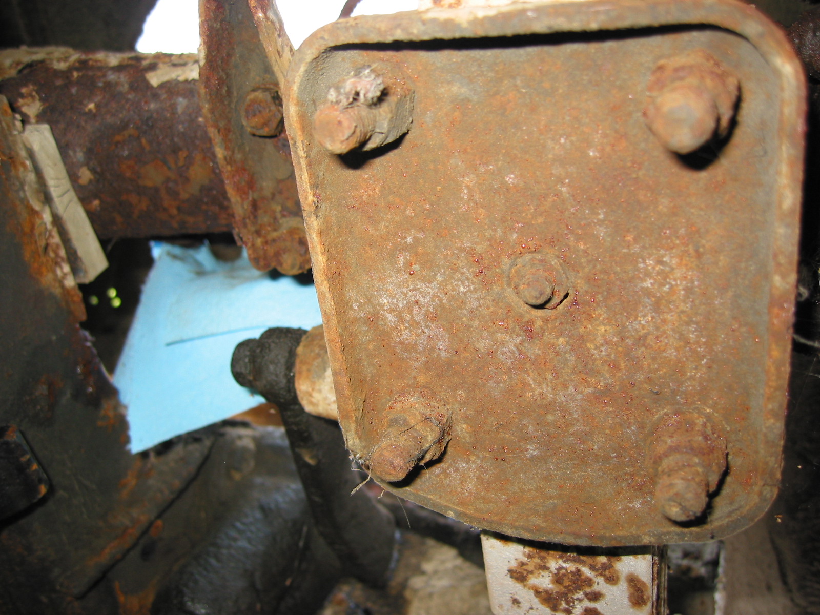
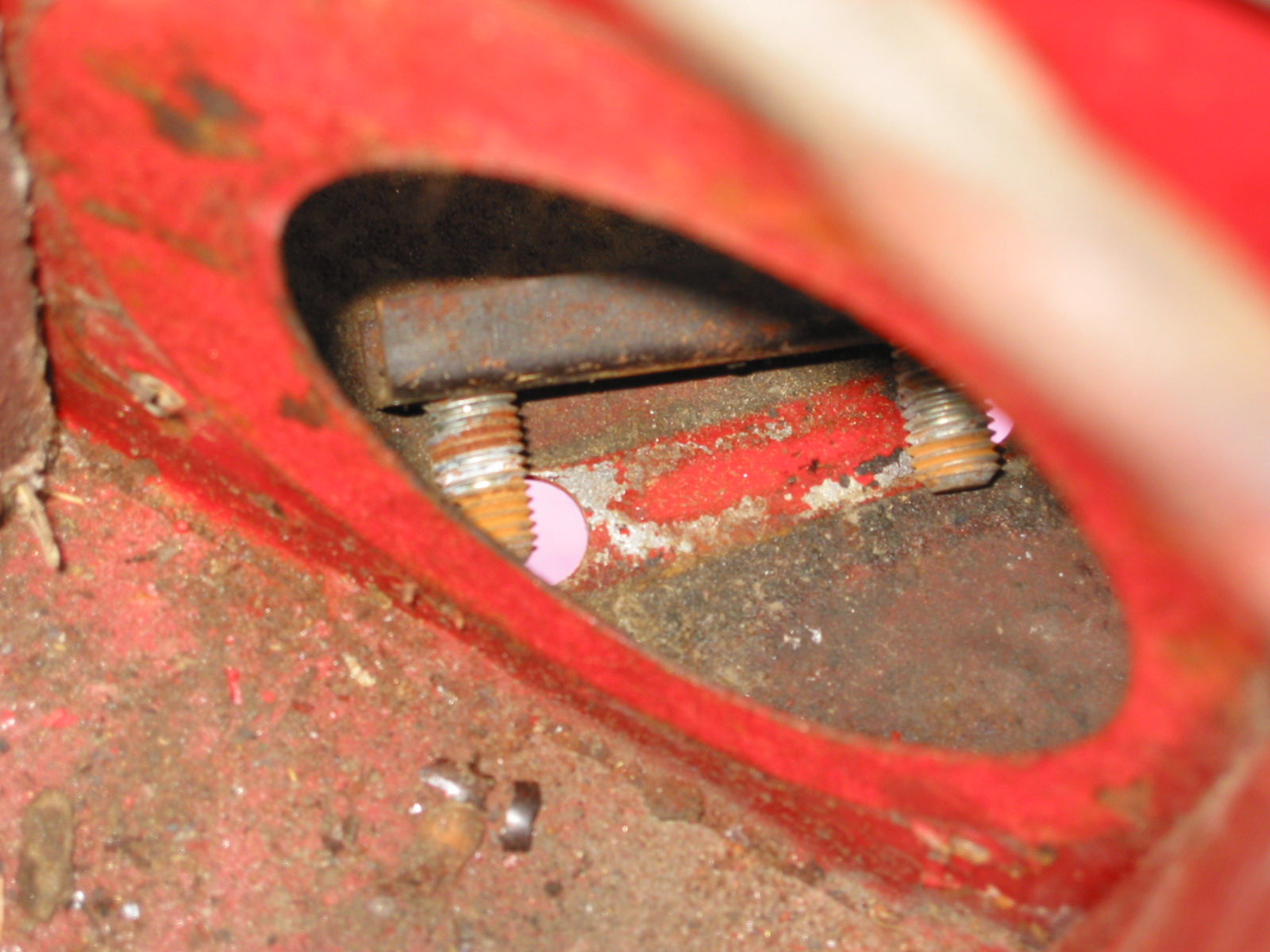
Rear Hubs – Removed the octagonal nut retaining the hub. One of the nuts loosens clockwise and one counterclockwise. Remove the O Ring, flat washer and retaining band. Remove the back plate by loosening 4 nuts and bolts. The bolt heads face the outside of the car. I ordered a special socket from BCS for this purpose.
left rear hub – nut removed
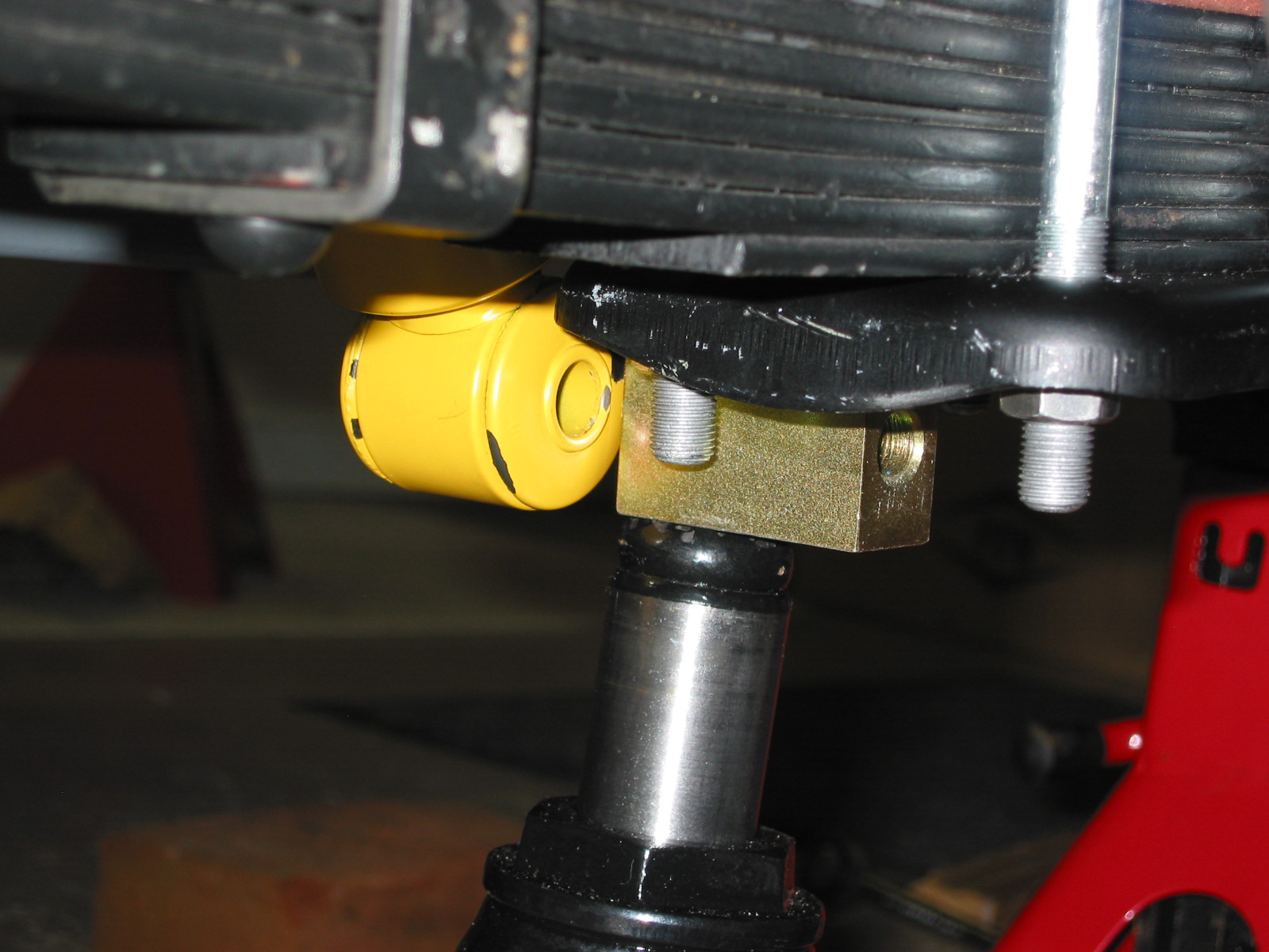
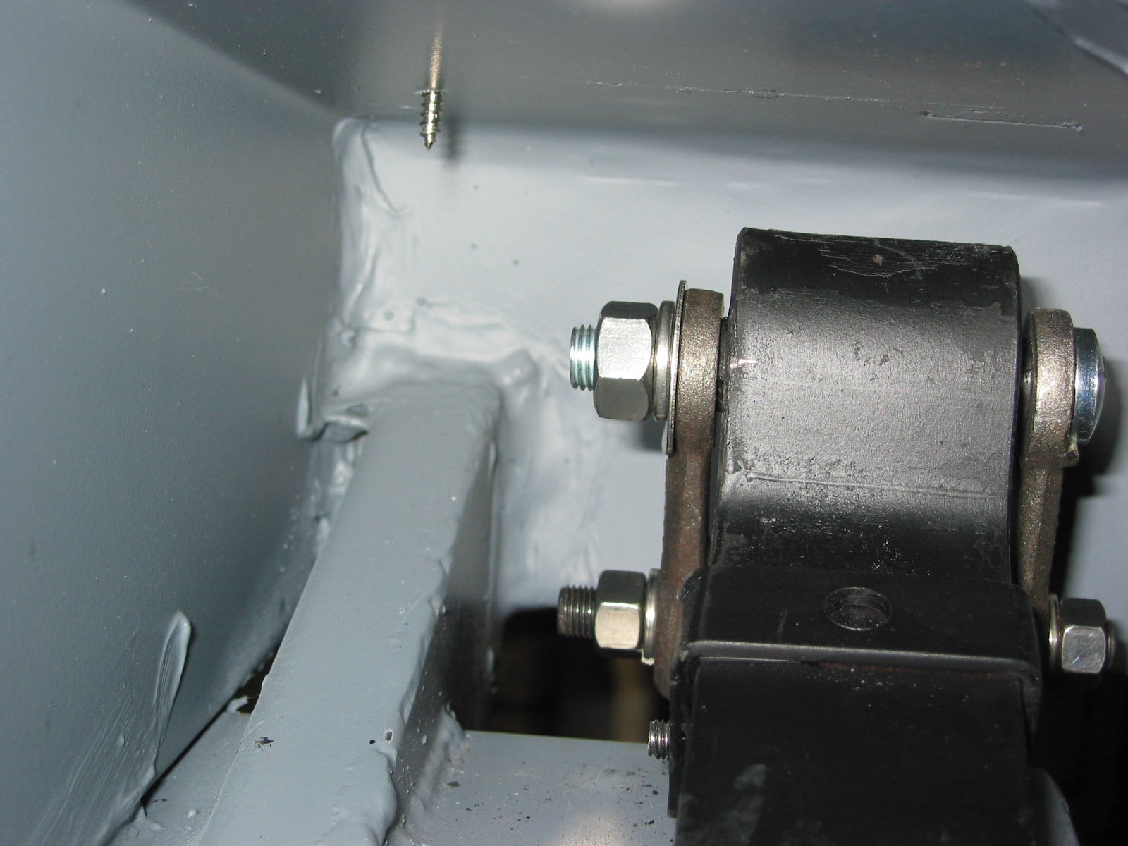
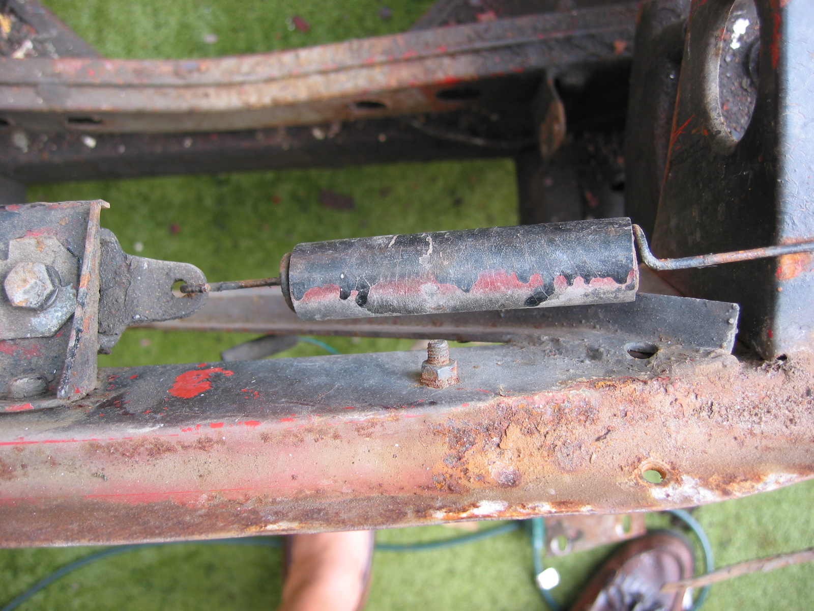
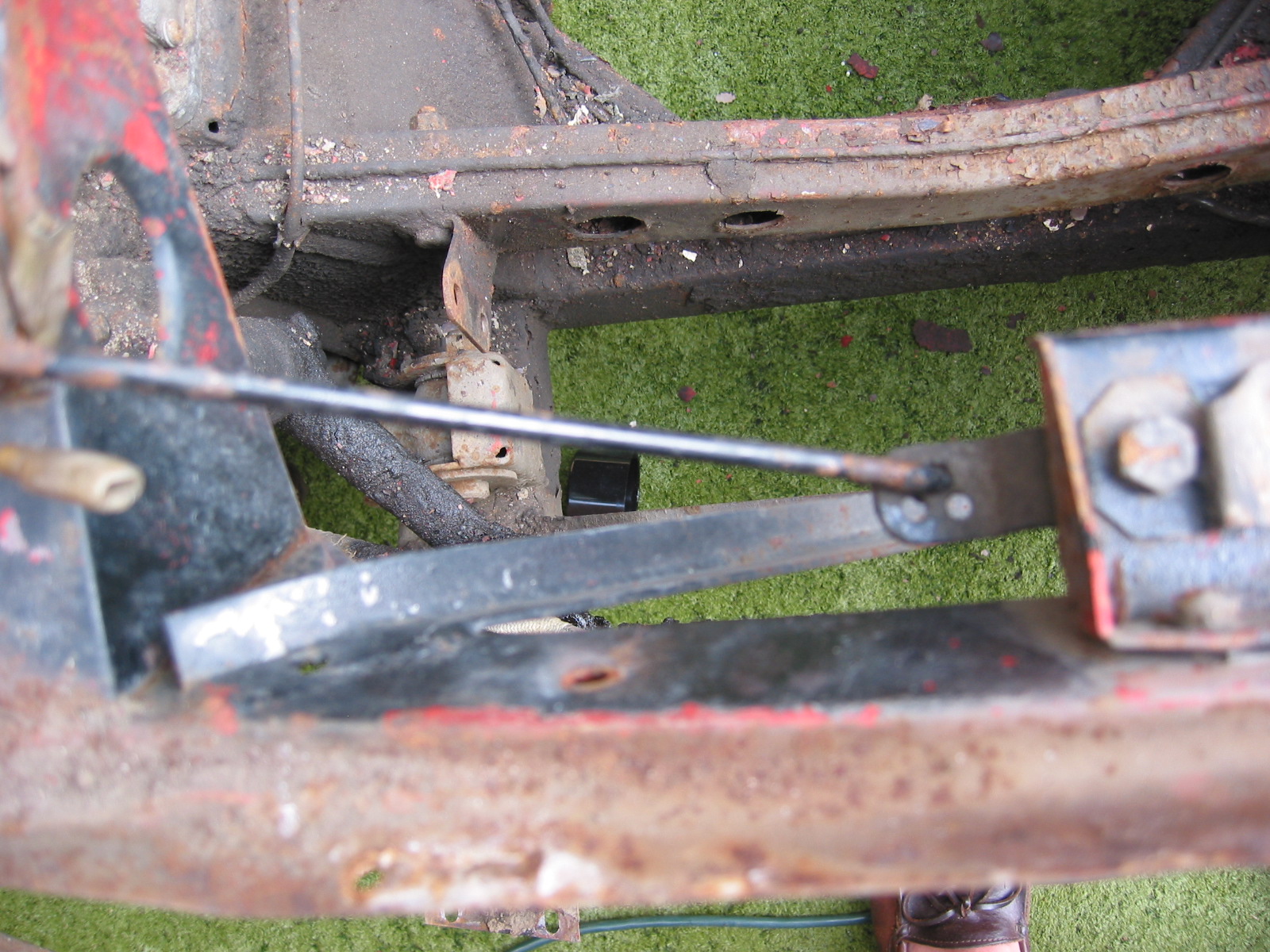
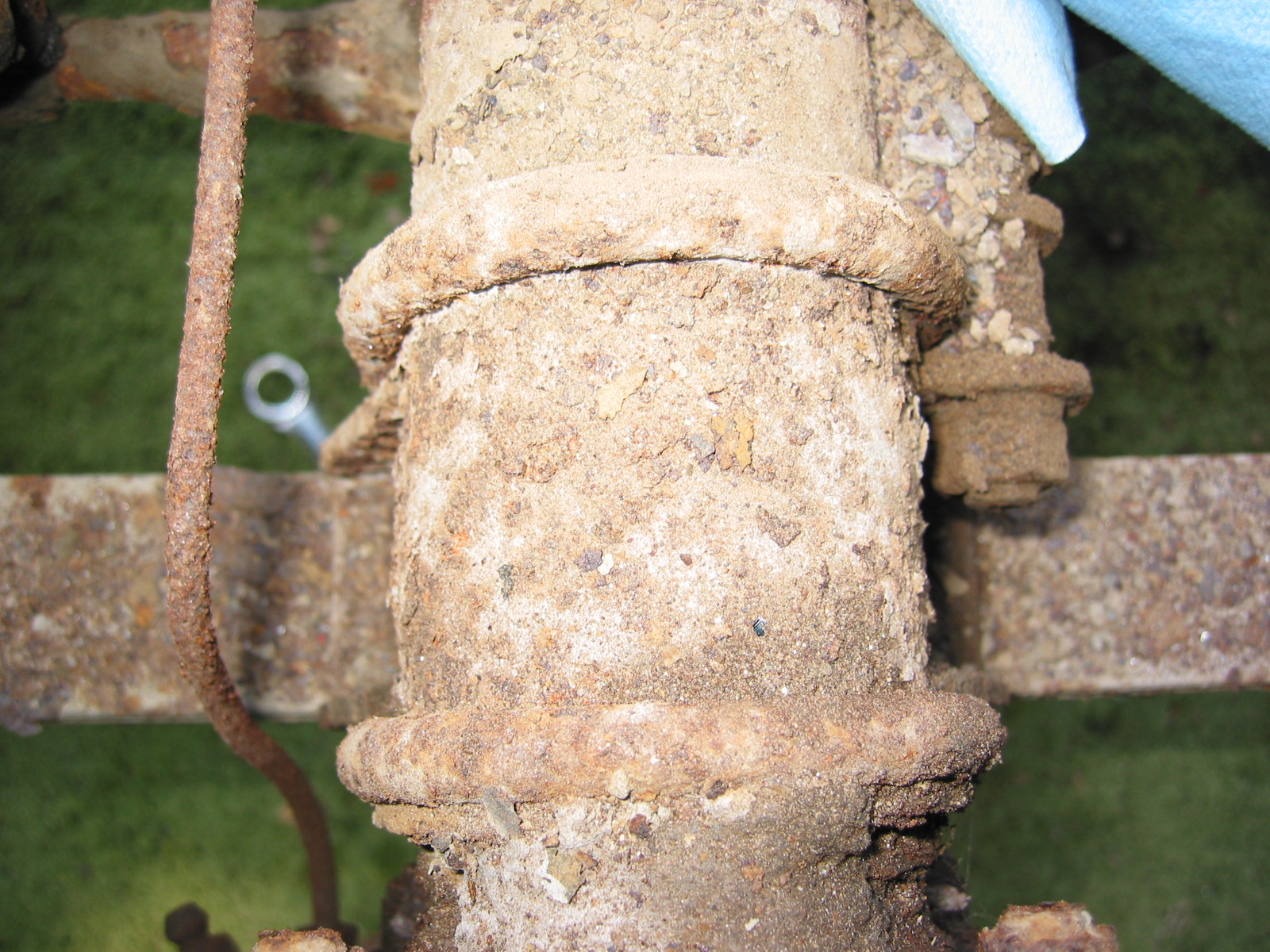
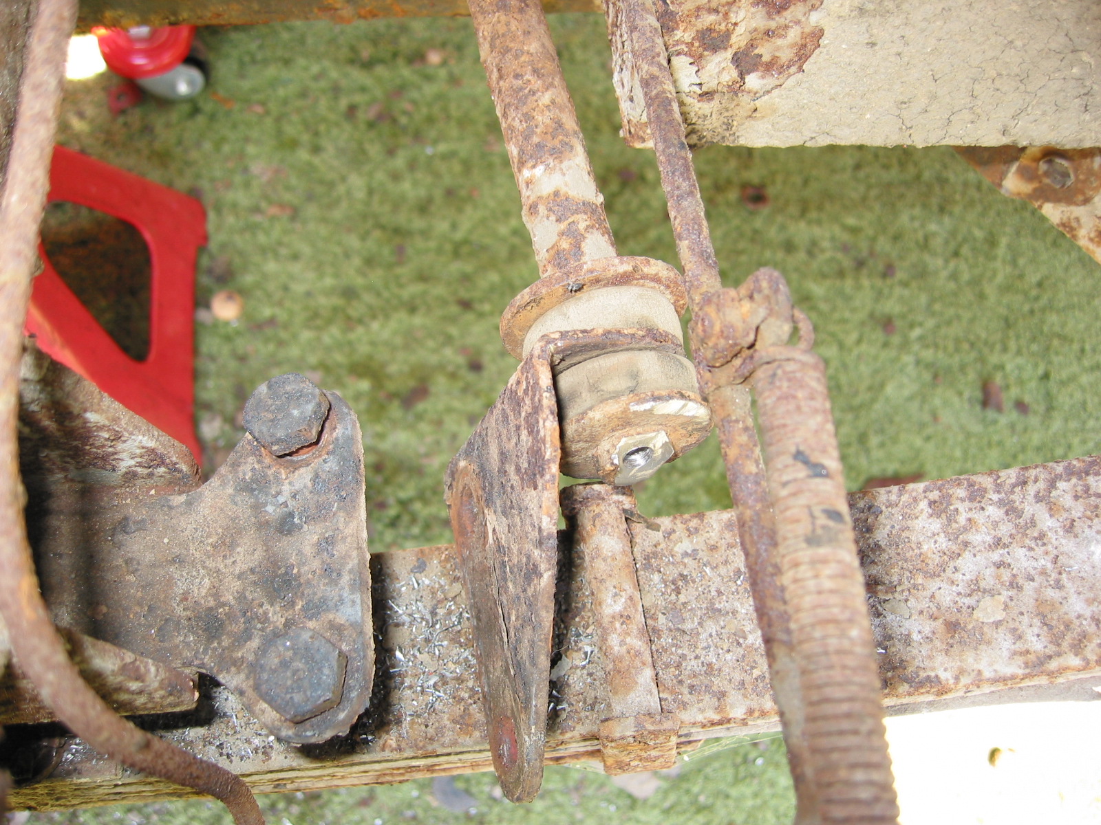
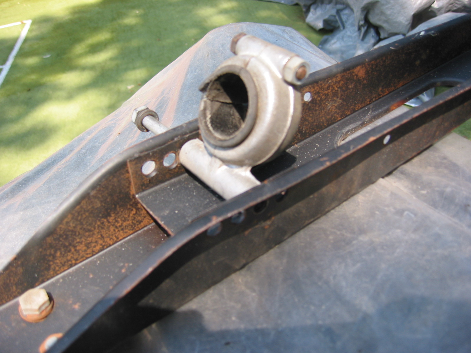
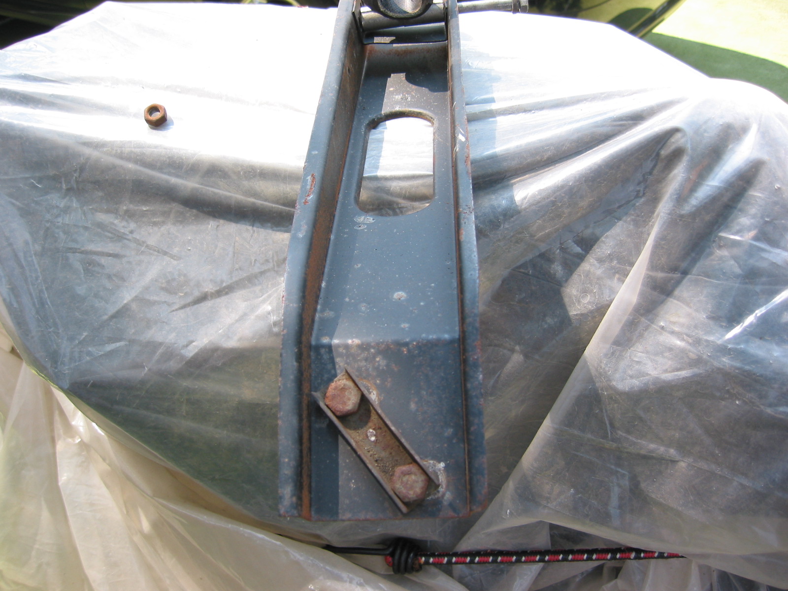
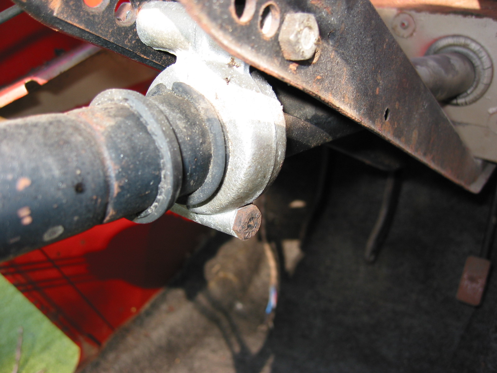
Shock Absorbers – Removed the rear shock absorbers by loosening 11/16” nut and kncked pin through the bushing and out of the bracket holding the shock.
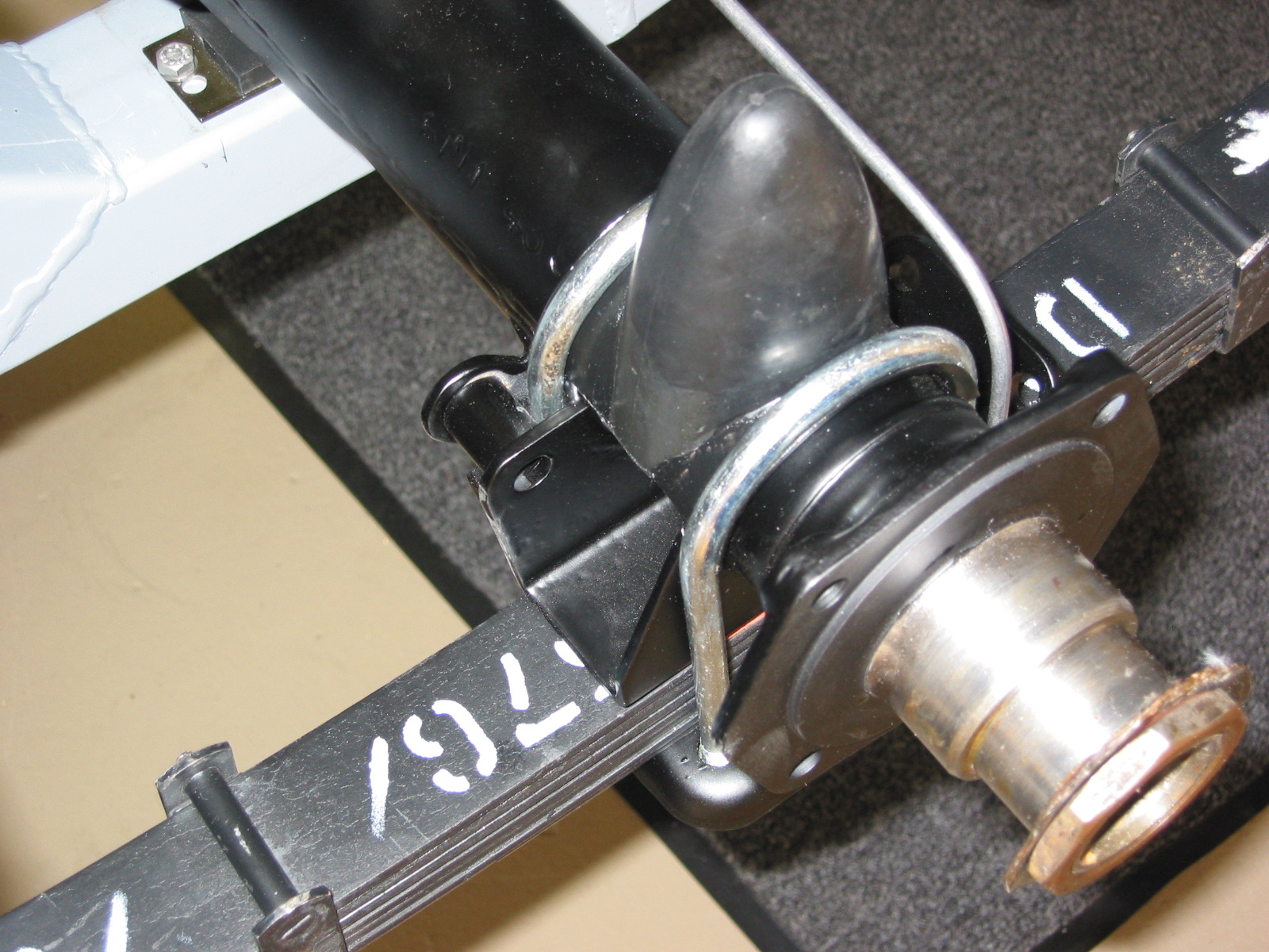
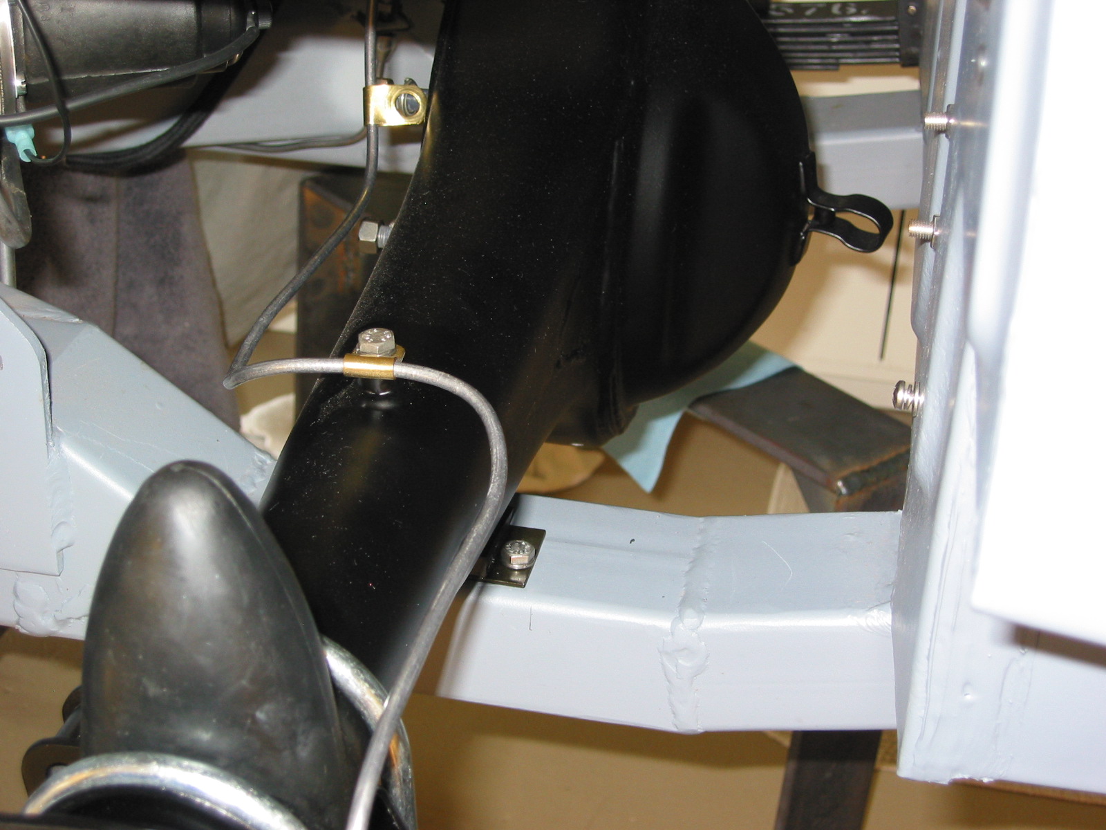
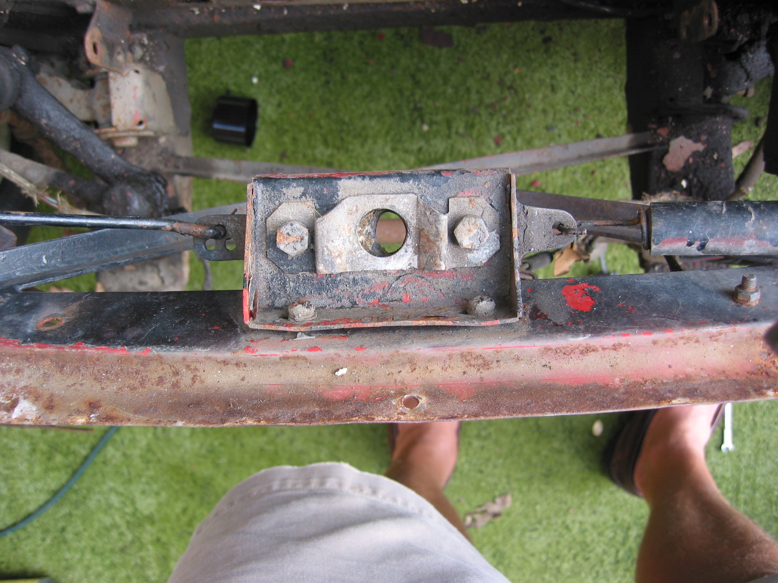
Rear Differential – Removed rear differential from axle by loosening 12 nuts and lock washers. Top center bolt also retains the brake line clamp.
November 29, 2002
Rear Hubs
Left Rear Hub – Used a slide hammer to loosen and remove the hub from the axle.
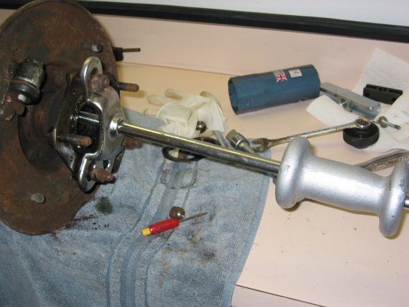
Hub removal-too Slide Hammer
After the hub is removed the bearings can be knocked out with an appropriate tool. The “made in England lettering is to the outside of the wheel. The paper gasket, and rubber “O” ring are removed as well. The hub also includes a rubber seal on the inside of the hub. I could not remove it, will have to learn the secret! Later learned the secret is a screwdriver. The left hub nut loosens “clockwise” and the right “counterclockwise.”
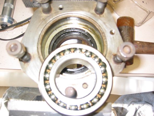
Rear bearings
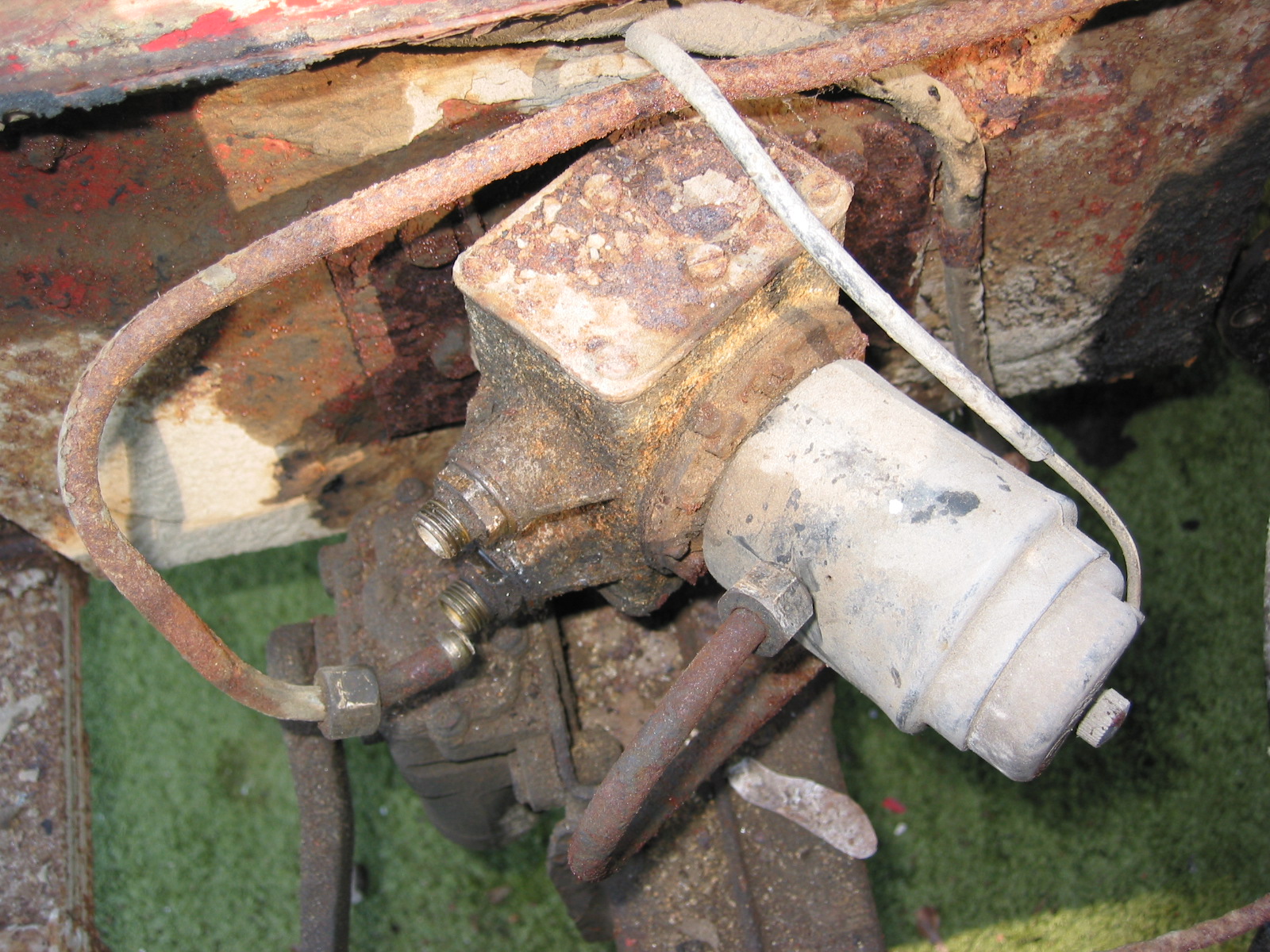
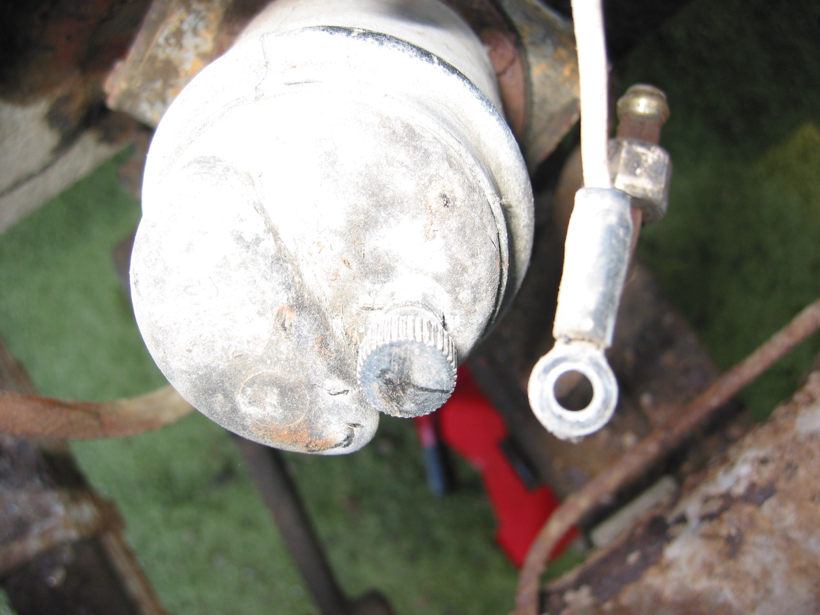
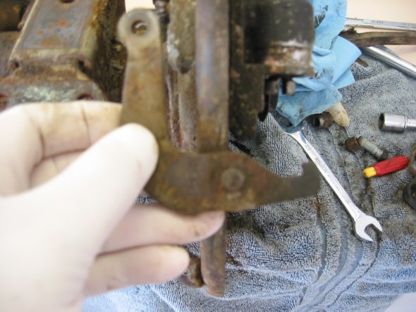
Brake Cylinders – Pulled off the retaining circlip from the rubber boot on the wheel cylinder. Remove the rubber boot cover and the rubber gasket from around the cylinder assembly. Pry apart the sliding plates that lock against one another. The lockplate with the tabs “up” goes against the backplate and the one with the open slots on the top. After removing the lower plate slide out the handbrake lever. Then take off the inside lockplate and remove the cylinder.
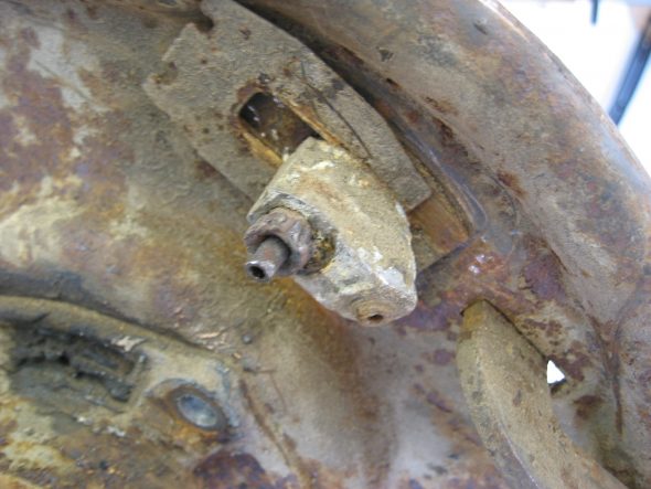
brake cylinder retainer clips

Brake cylinder retainer clips 2
handbrake lever
Shoe Adjuster – by loosening two nuts, note the position of the adjuster piston. Remove backplate by loosening the four retaining nuts and bolts. Finally, clean up the rear axle.
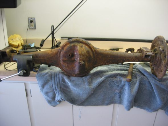
rear axle clean up
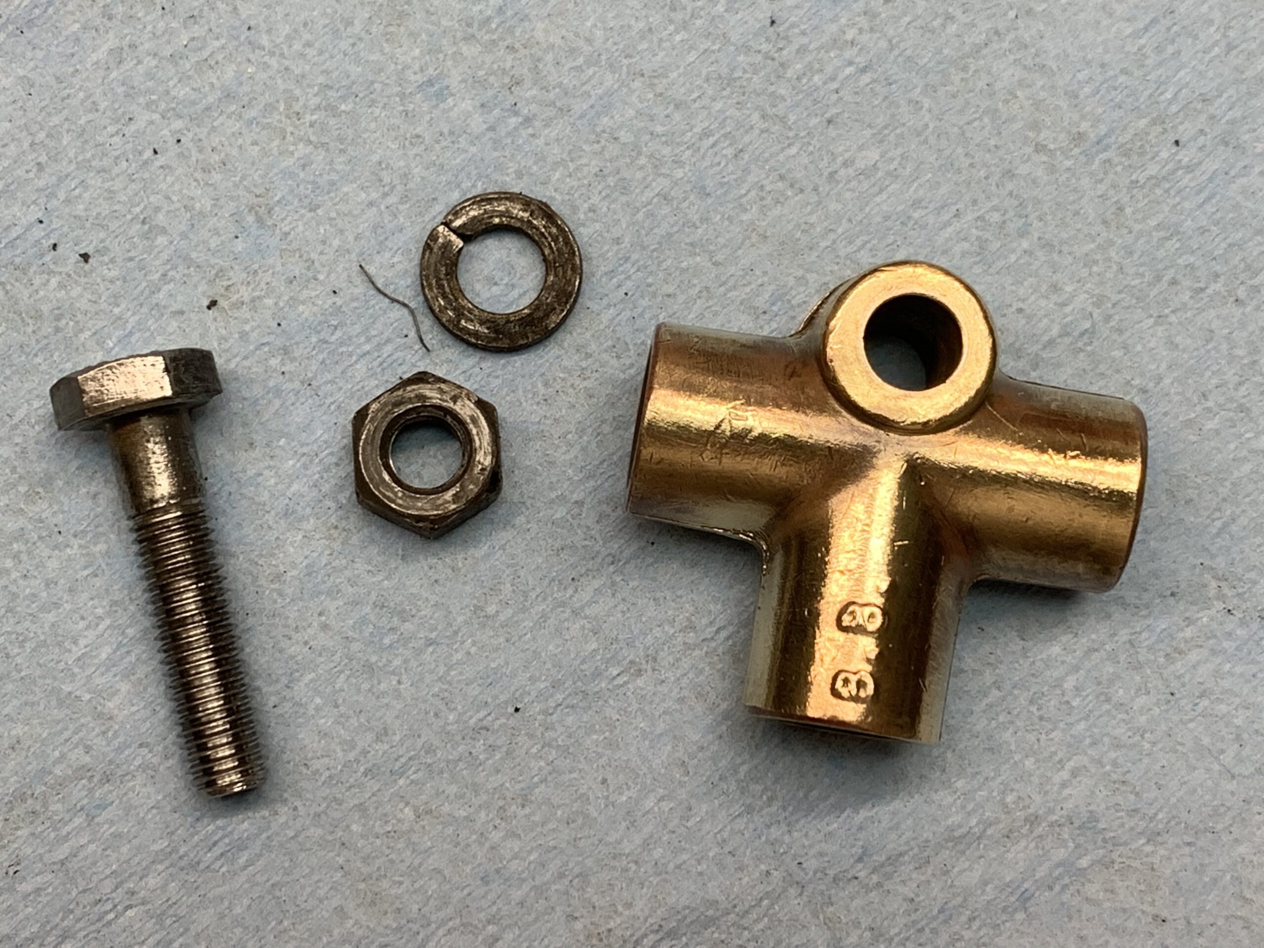
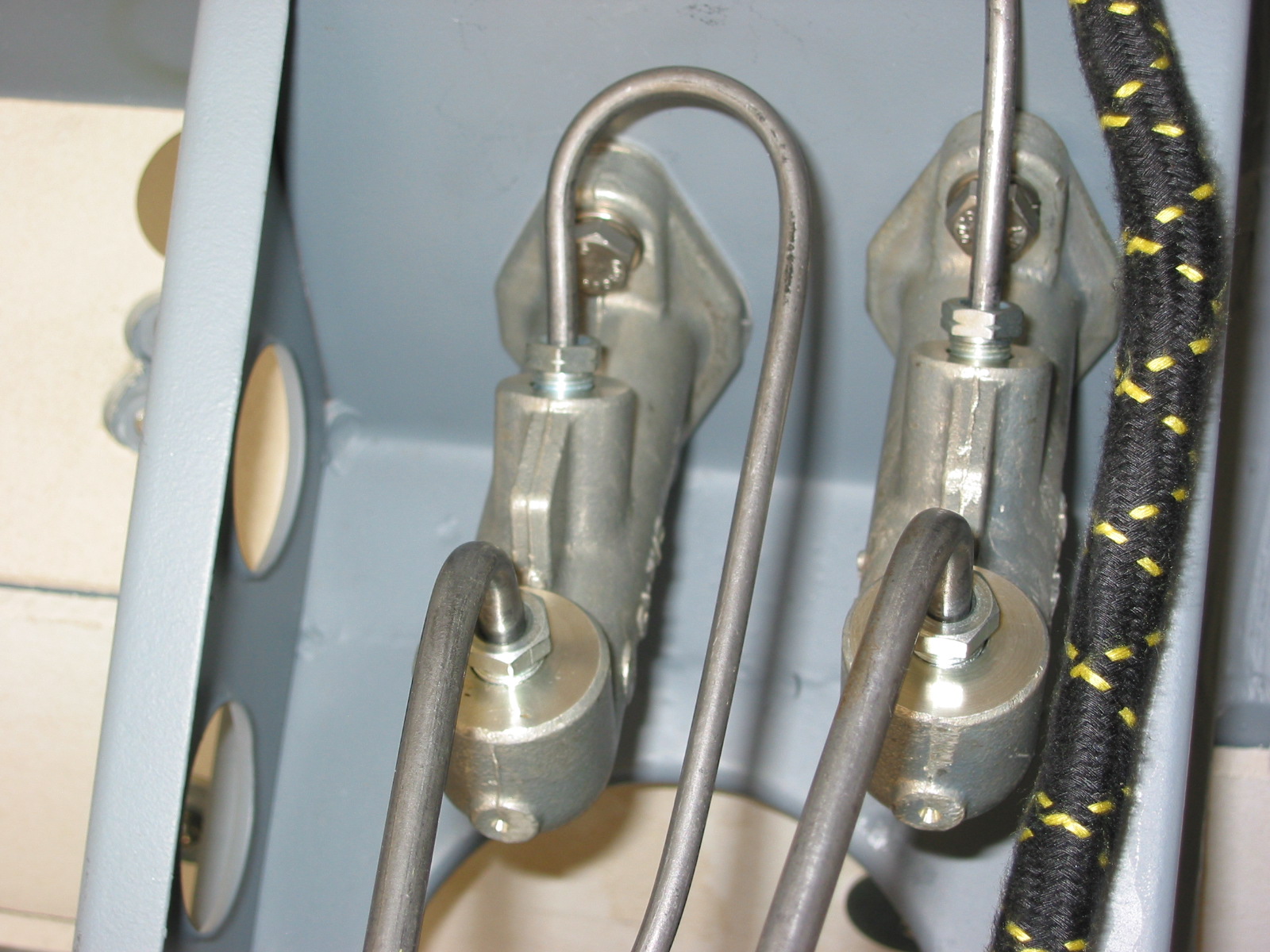
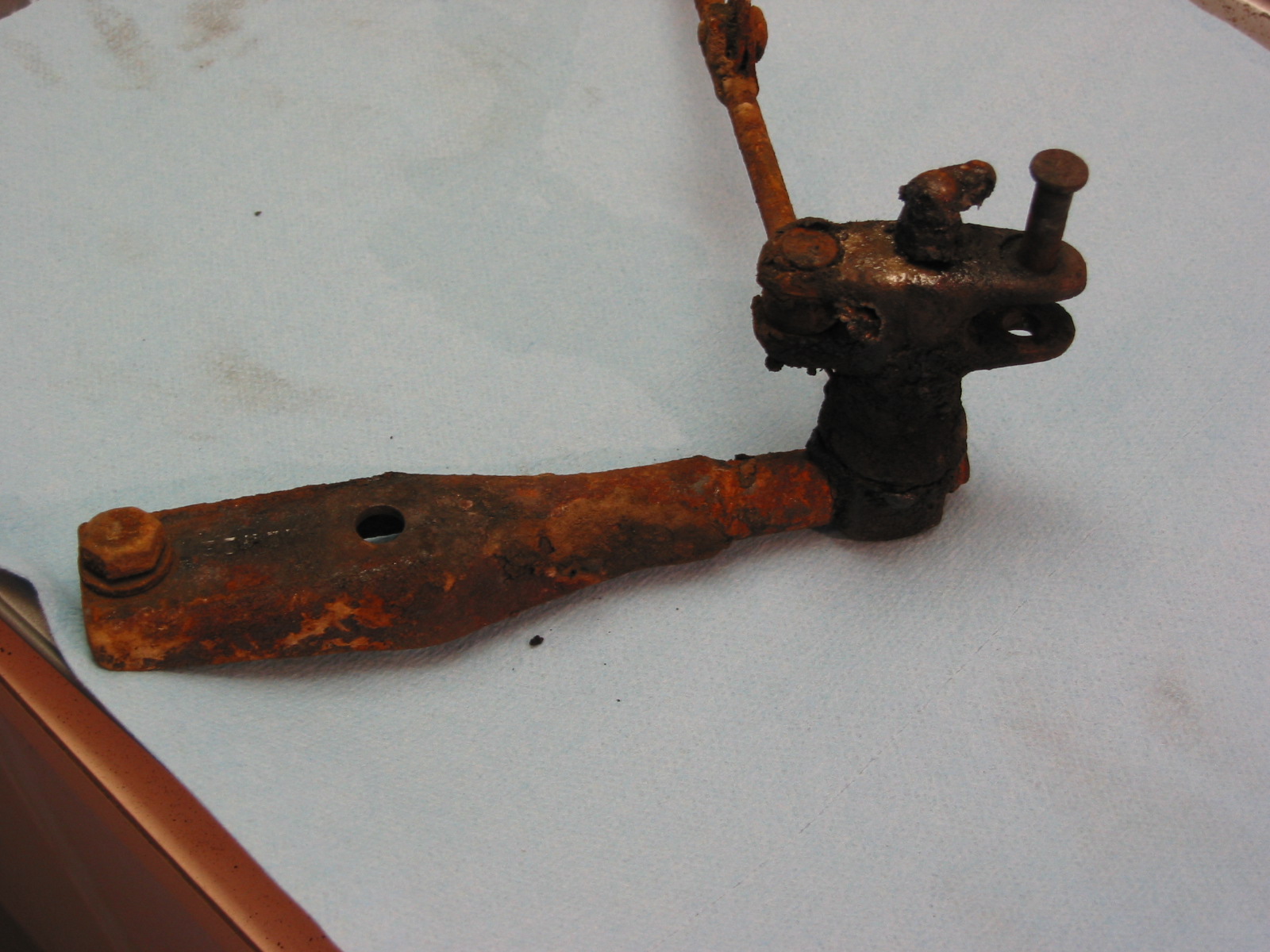
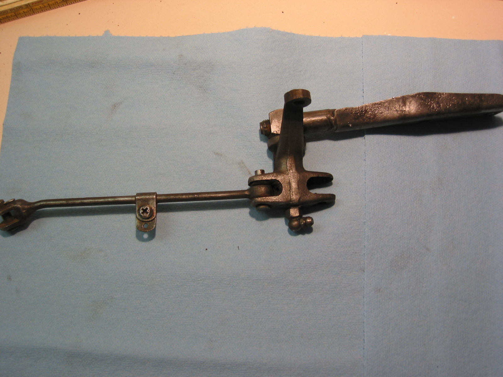
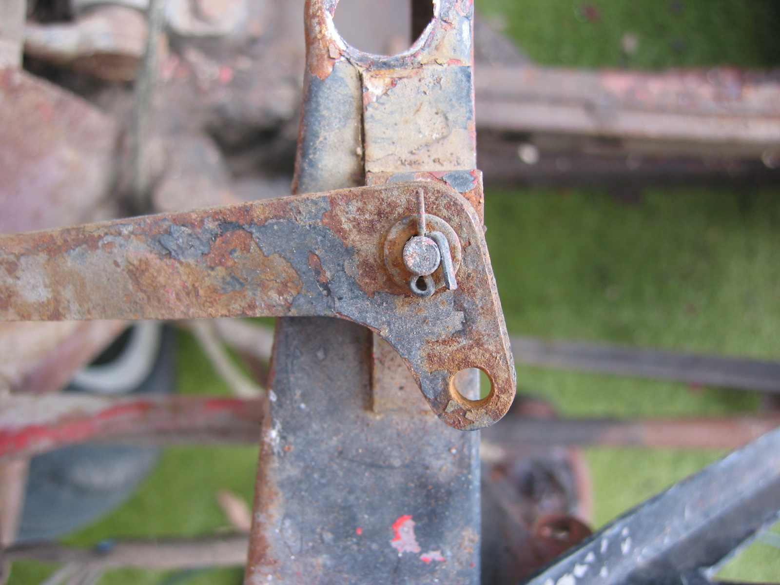
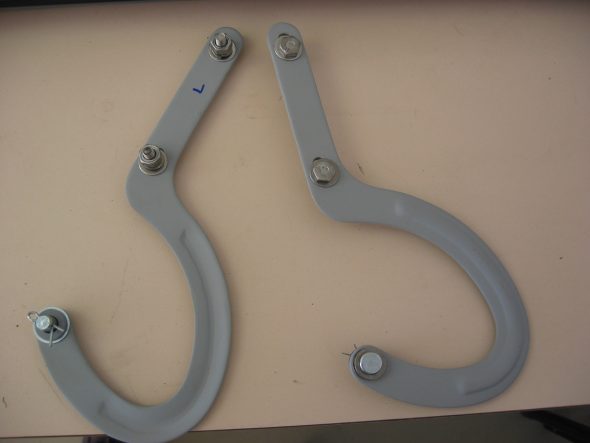
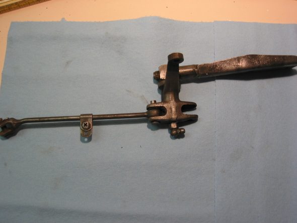
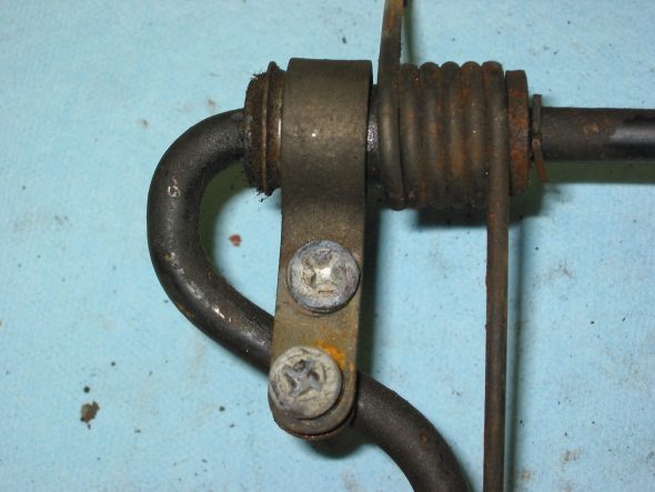
The handbrake lever assembly – was removed, disassembled and cleaned. Note the replacement of the cloth/rubber “O” ring under the large nut, and felt washers at the connecting pins. The bracket itself can be removed by loosening two 5/16” – 24 x 3/4” bolts and nuts. The mounting clip for the return spring is located 2 1/4” from the post.
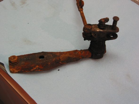
handbrake bracket 1
Handbrake Bracket 2

Handbrake spring location
Handbrake Bracket 4
January 25, 2003
This report is the first of my second year of working on the restoration of 4422! Lots of work remains in the disassembly and clean up stage before reassembly can begin. But progress has been made!
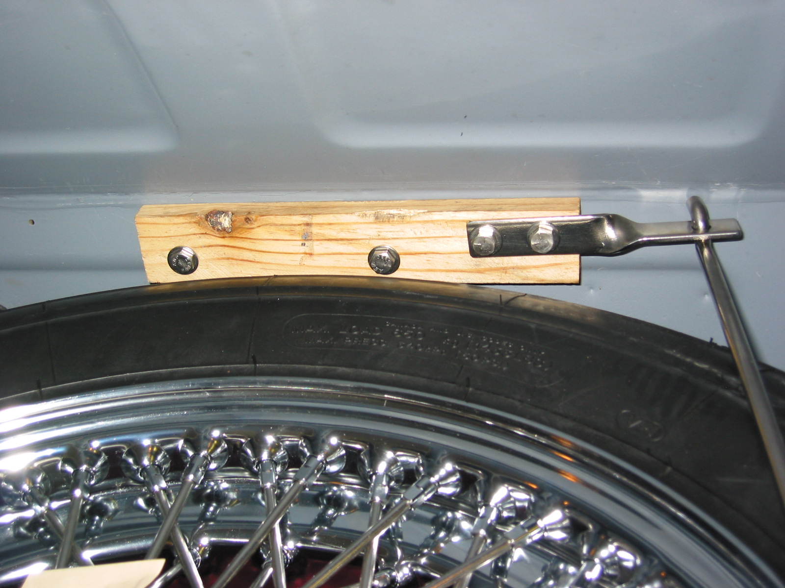
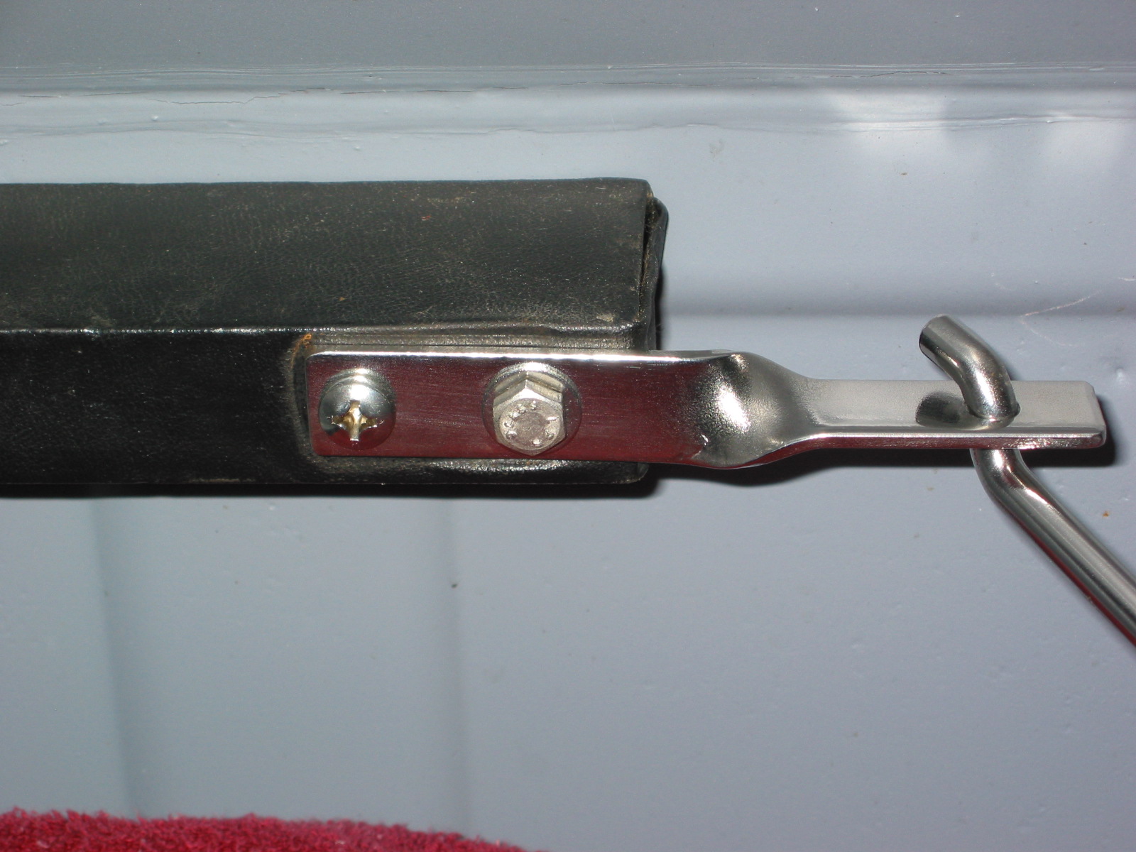
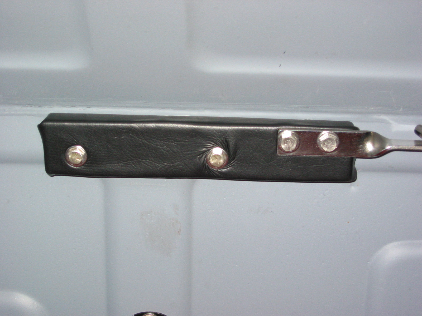
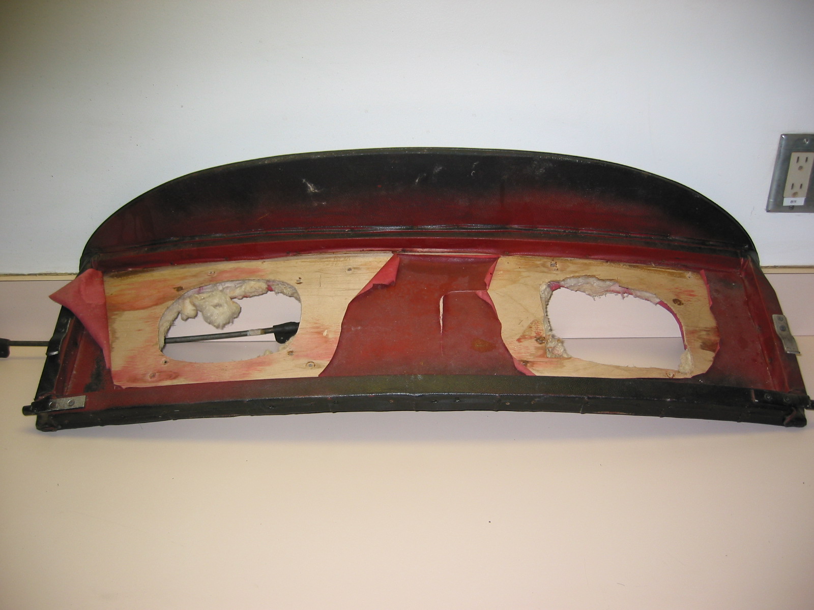
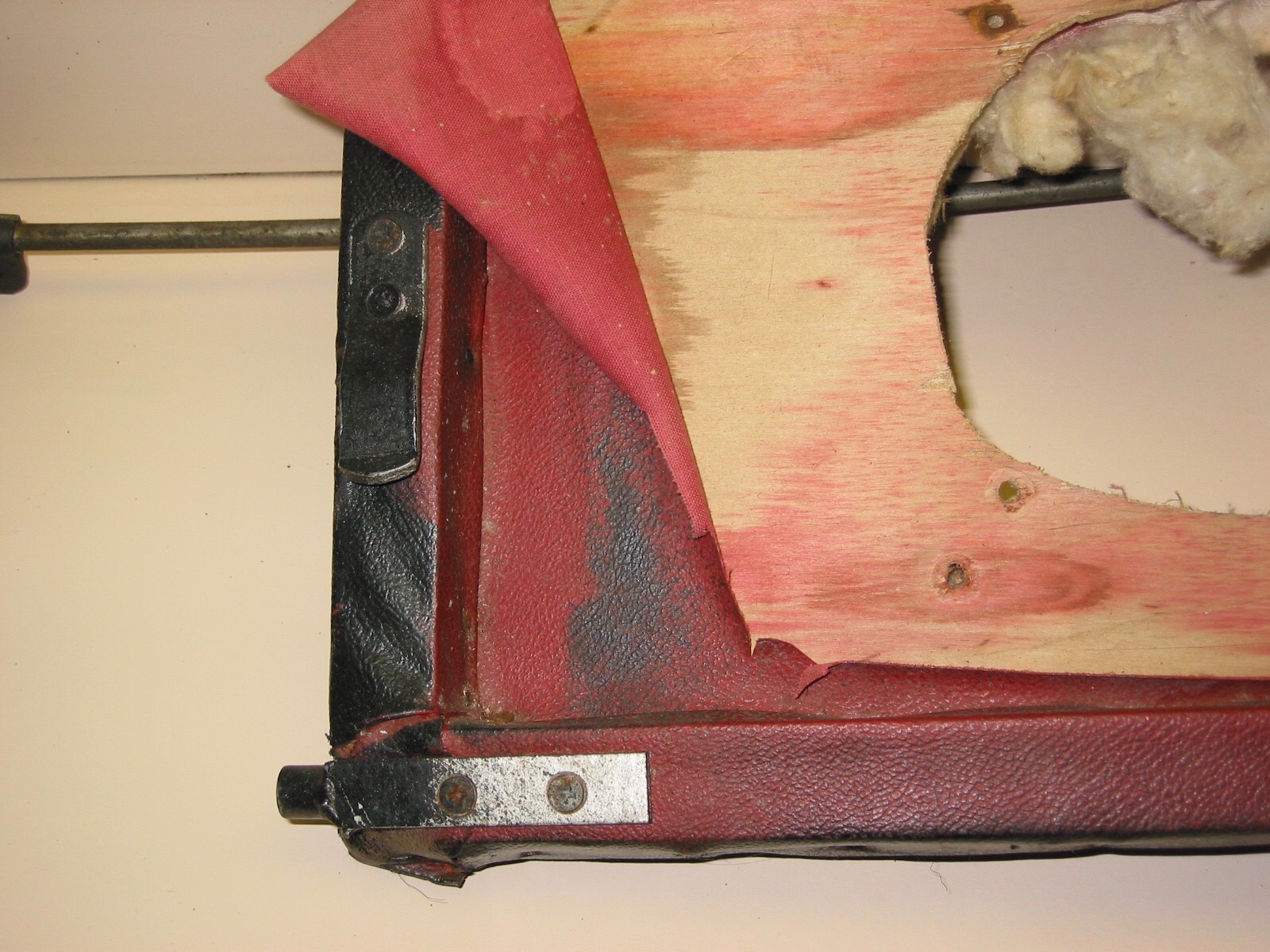
Rear Seat Back
Unfortunately, I had installed speakers in the panel when in college. So I will need to buy a new squab or at least the plywood flat pieces before recovering.

Rear Seat Back Panel 1
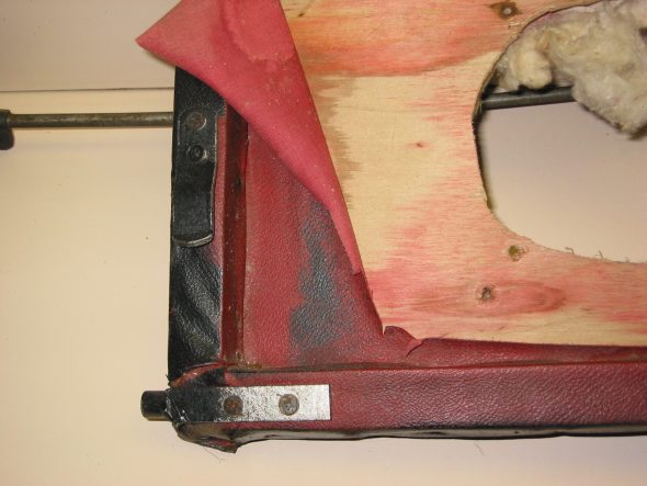
Rear Seat Back Panel Clips
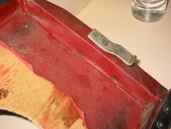
Rear Seat Back Panel 2
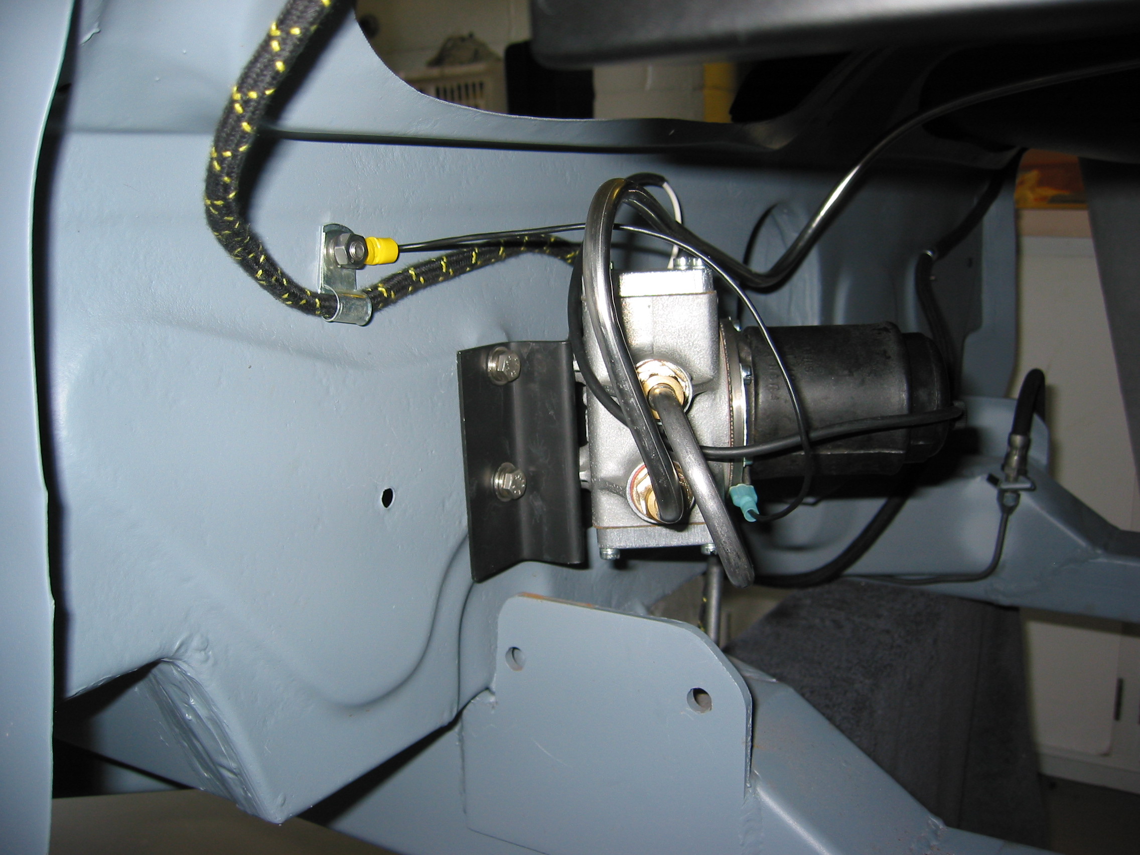
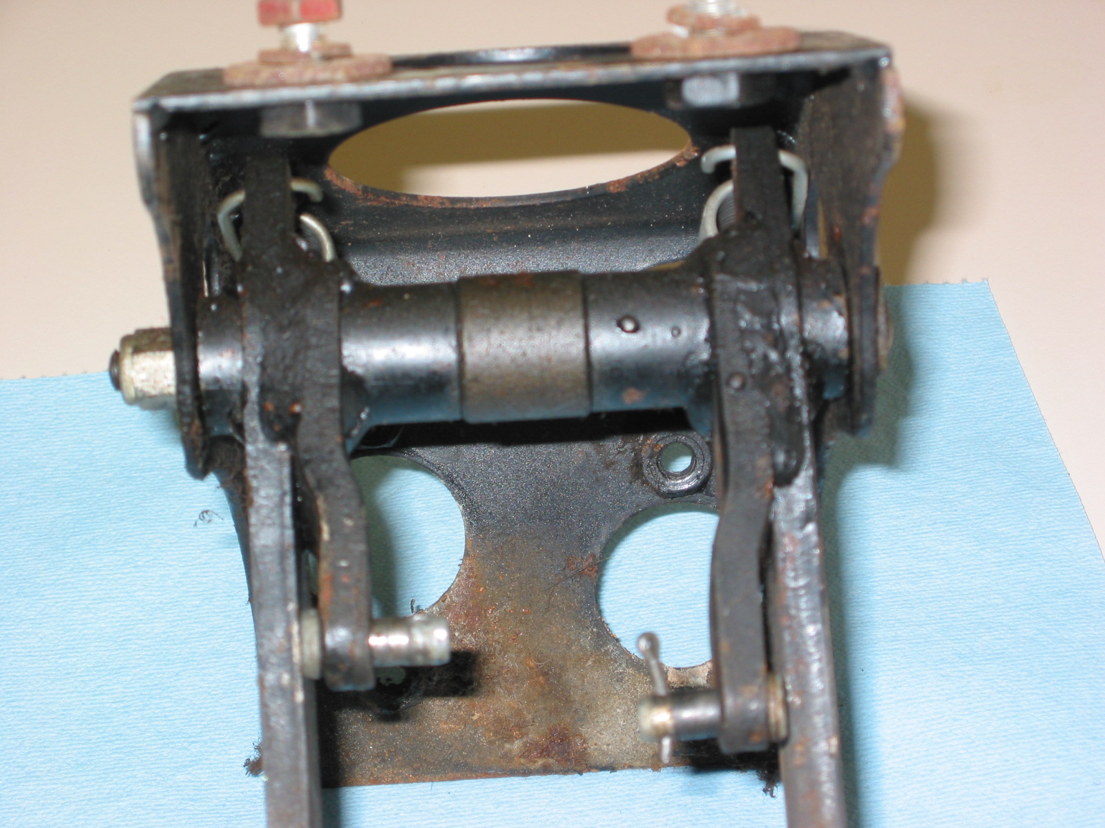
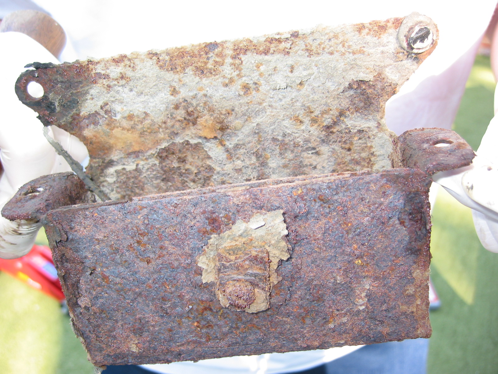
Clutch and Brake Pedal Bracket (Pedal box) -The box and parts were in very good shape. It was now time to disassemble and clean.
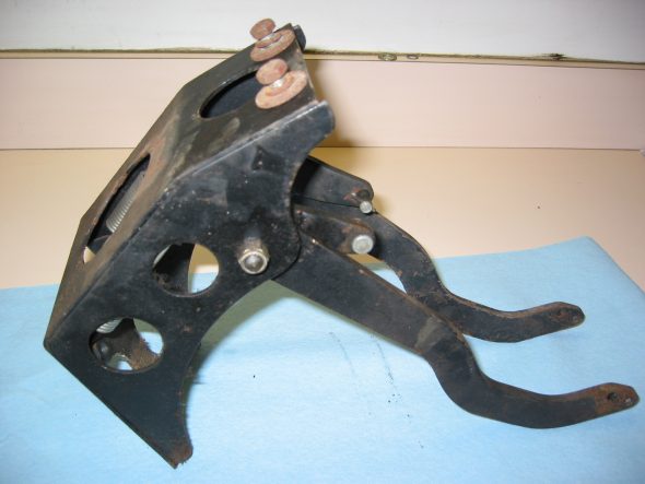
Pedal Box Assembly
Pedal Box Assembly 2
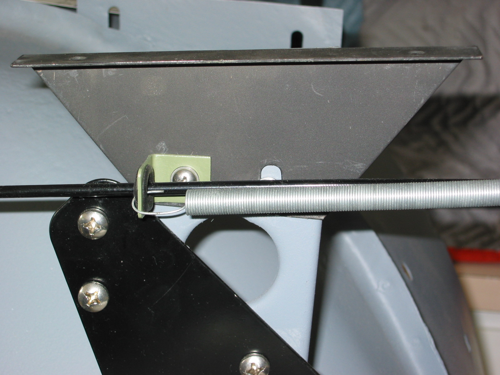
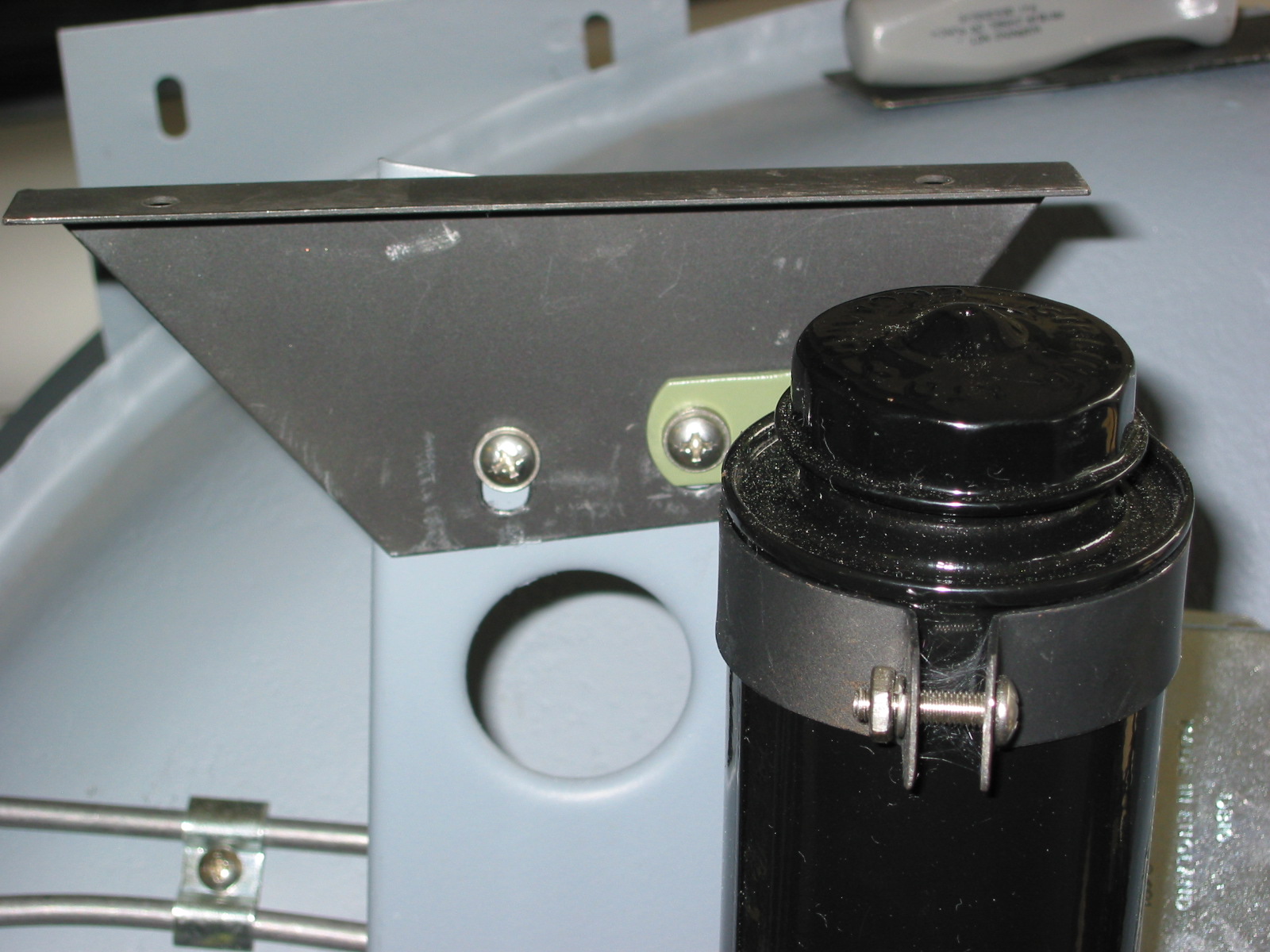
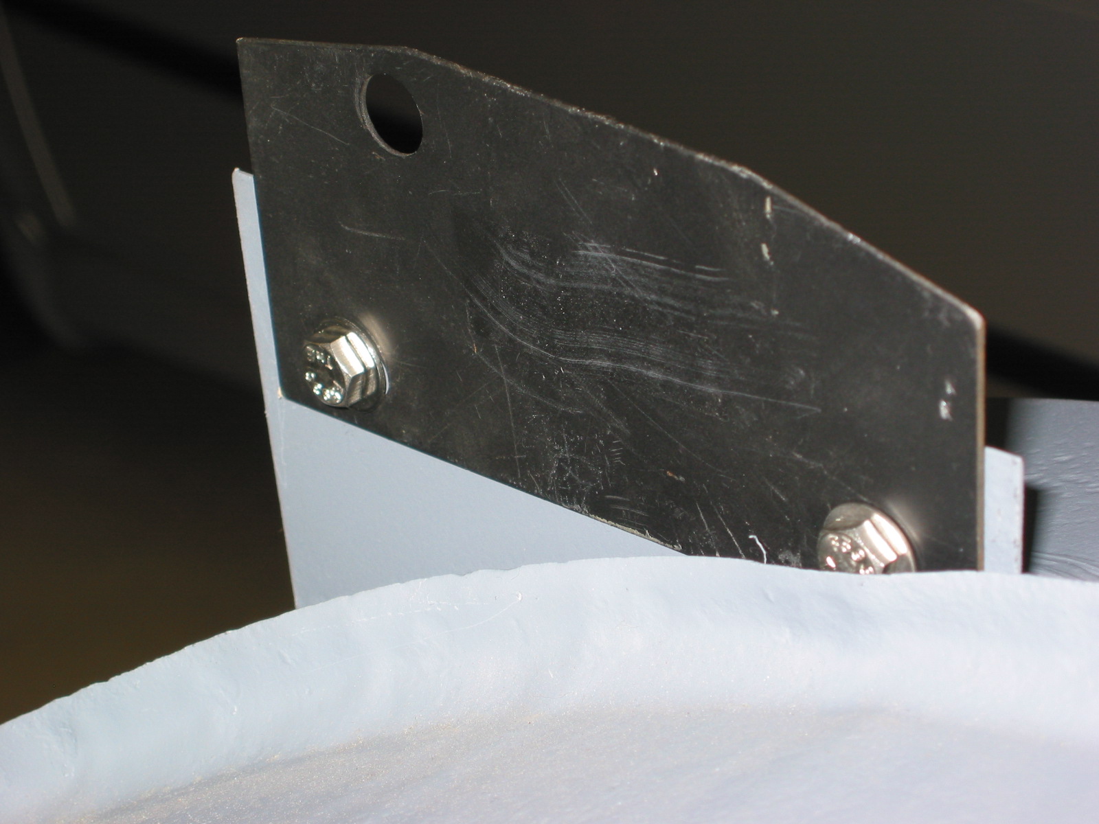
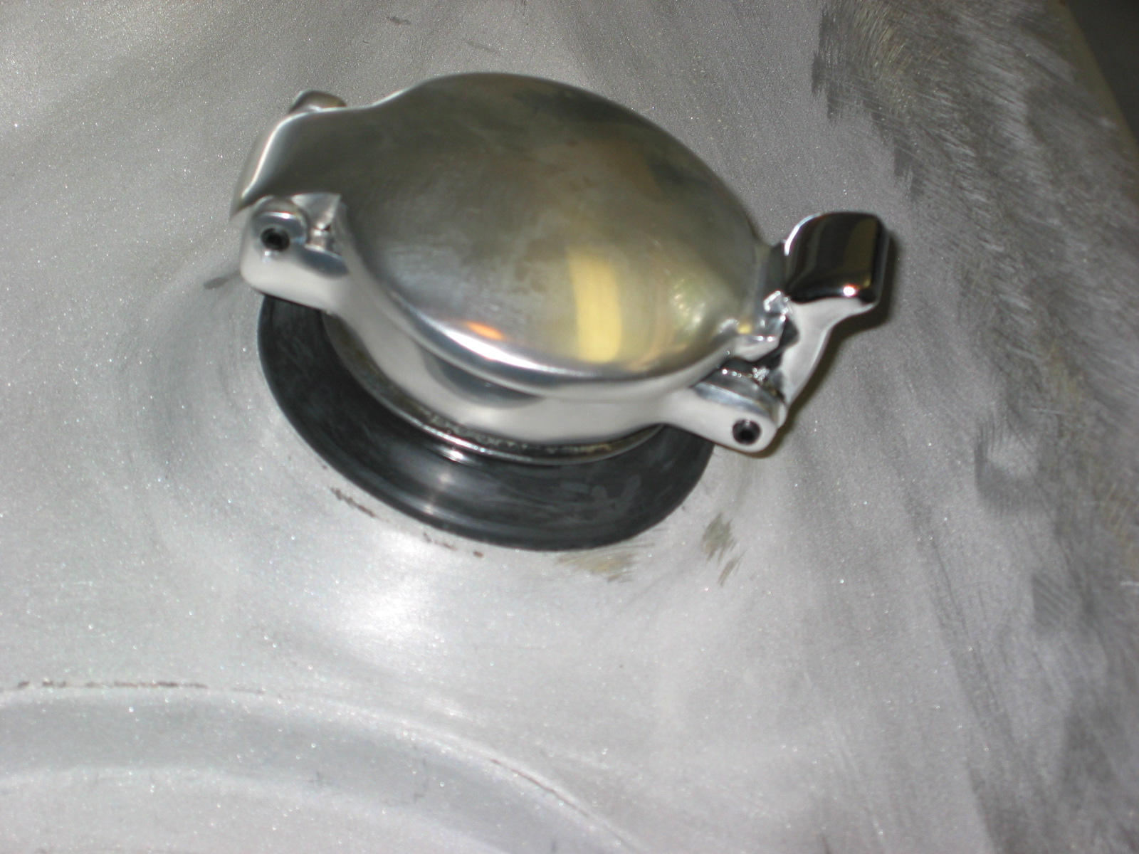
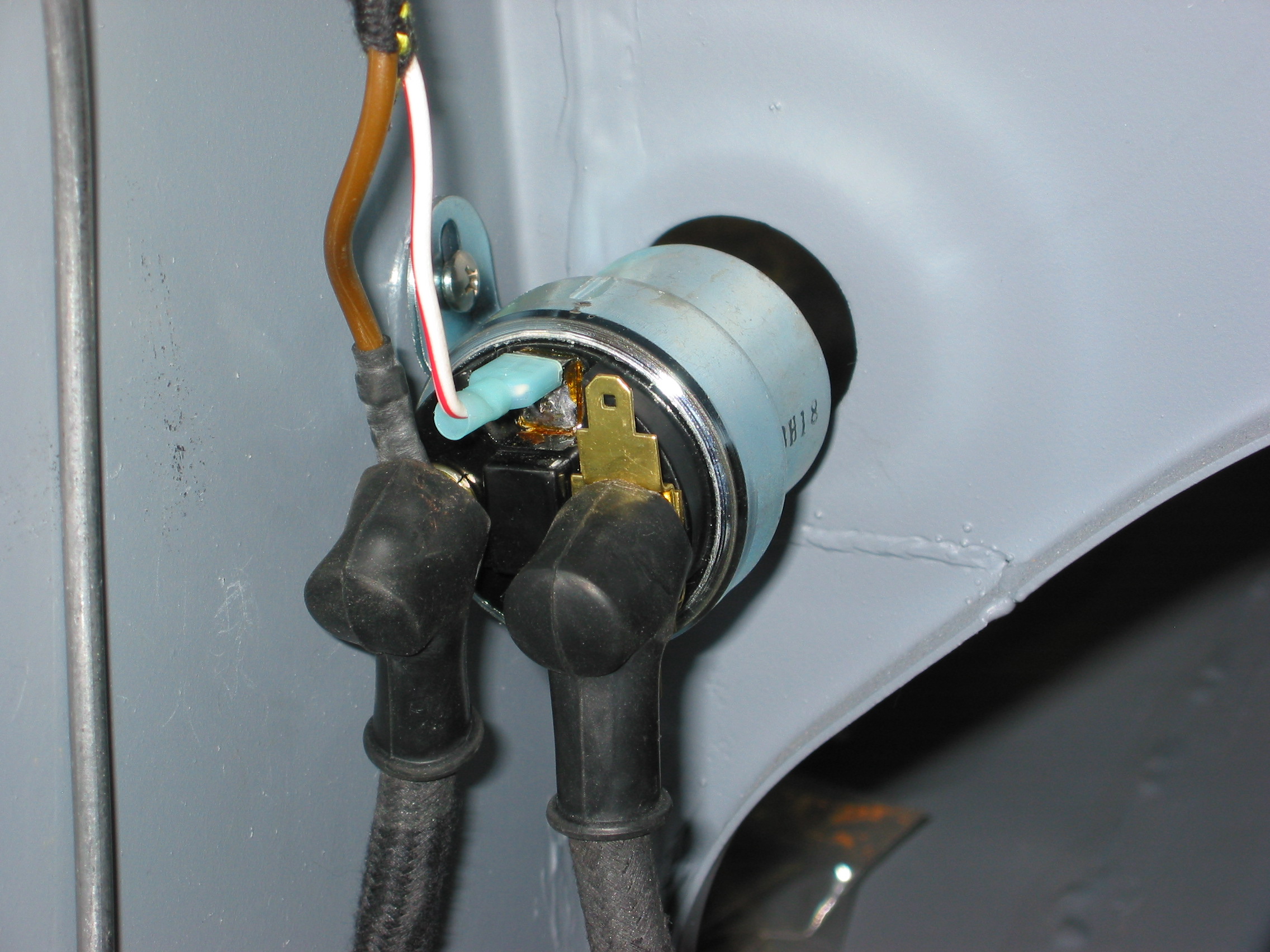
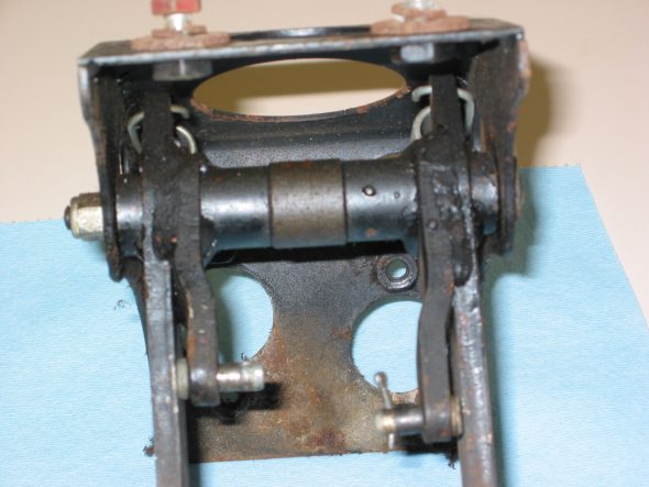
Striker pin assembly – The bonnet catch was a bit rusty, but restorable.
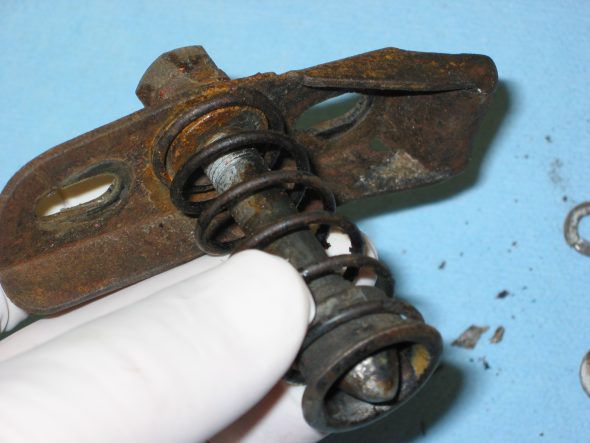
Bonnet Catch Striker Assembly 1
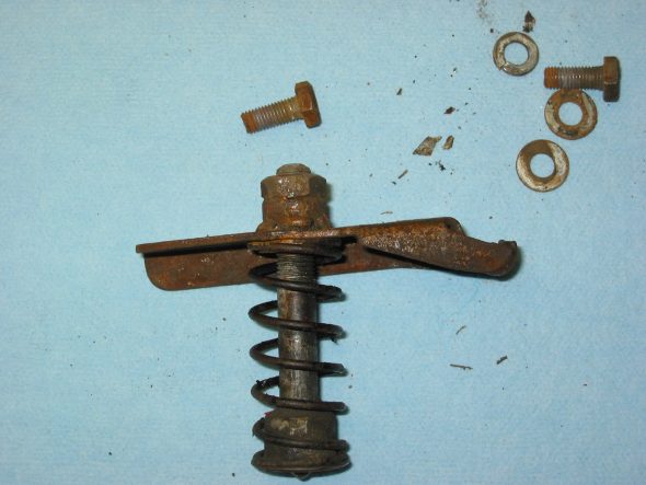
Bonnet Catch Striker Assembly 3
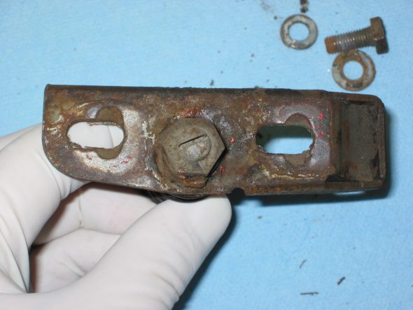
Bonnet Catch Striker Assembly 2
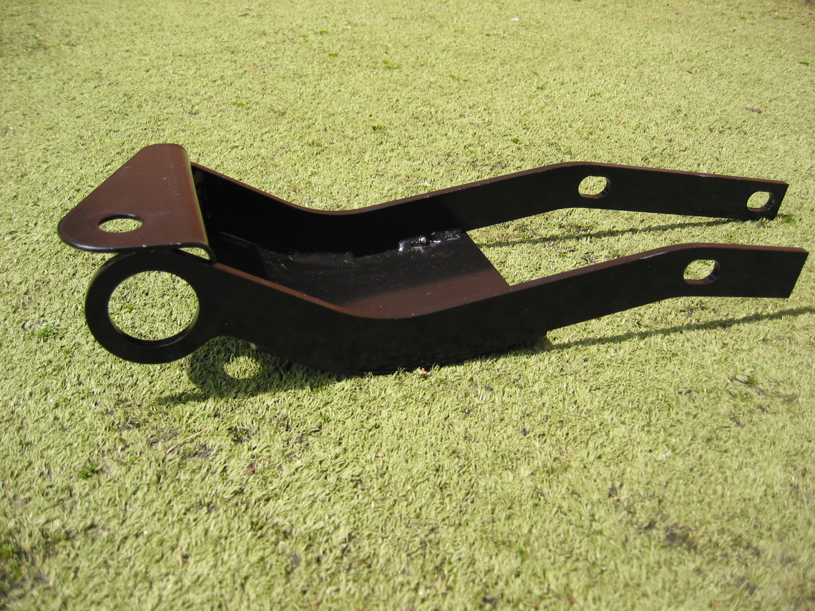
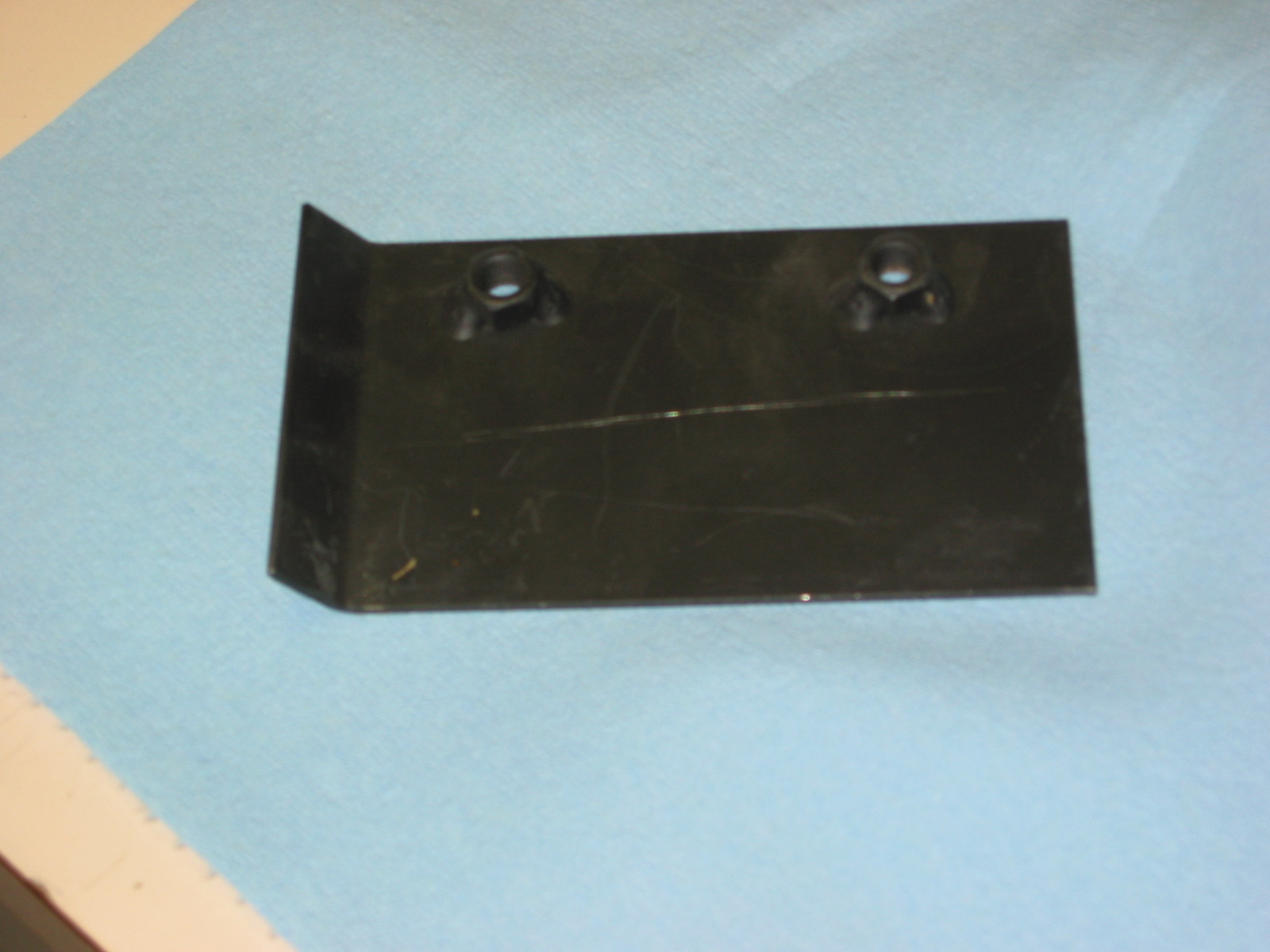
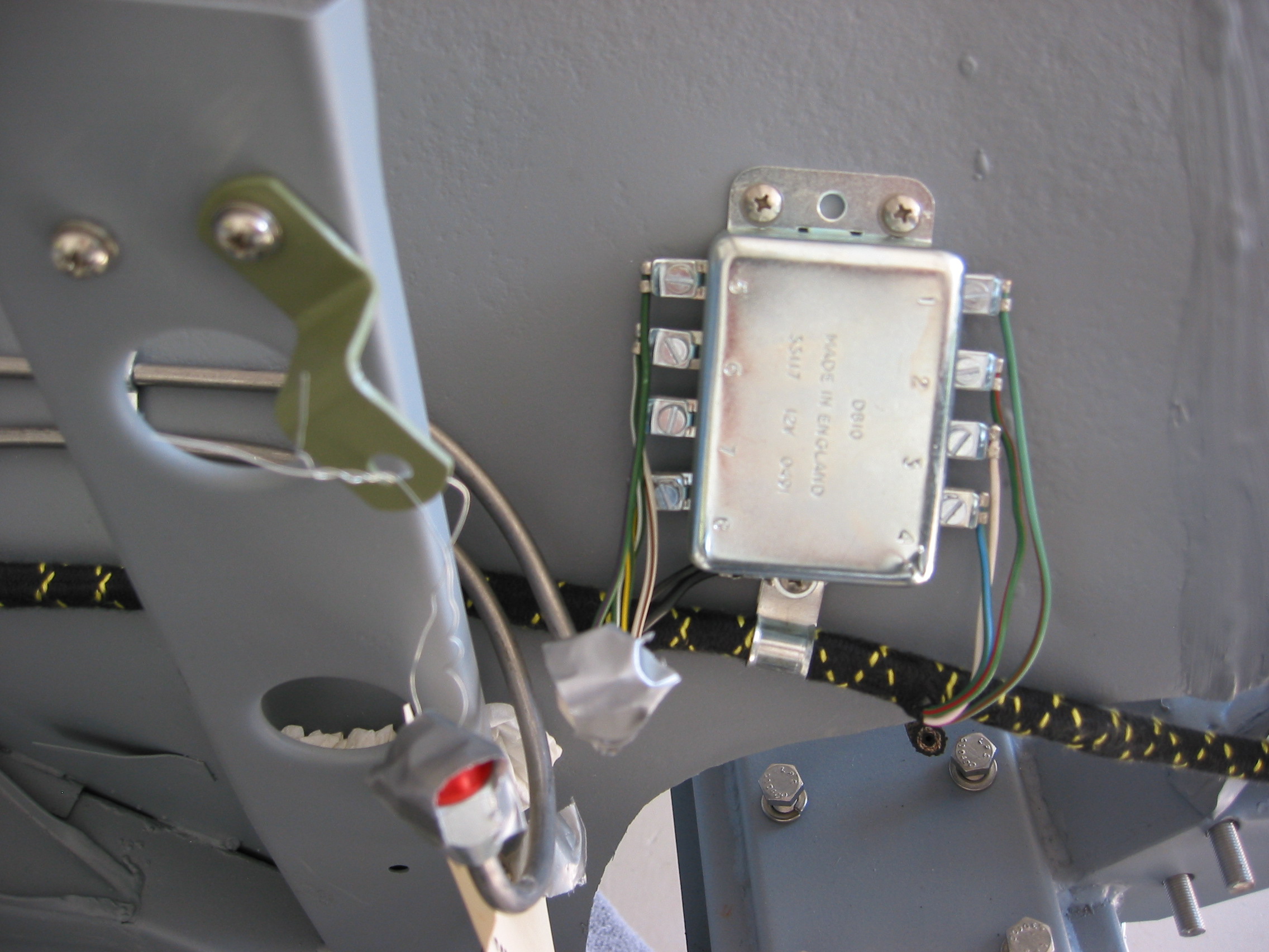
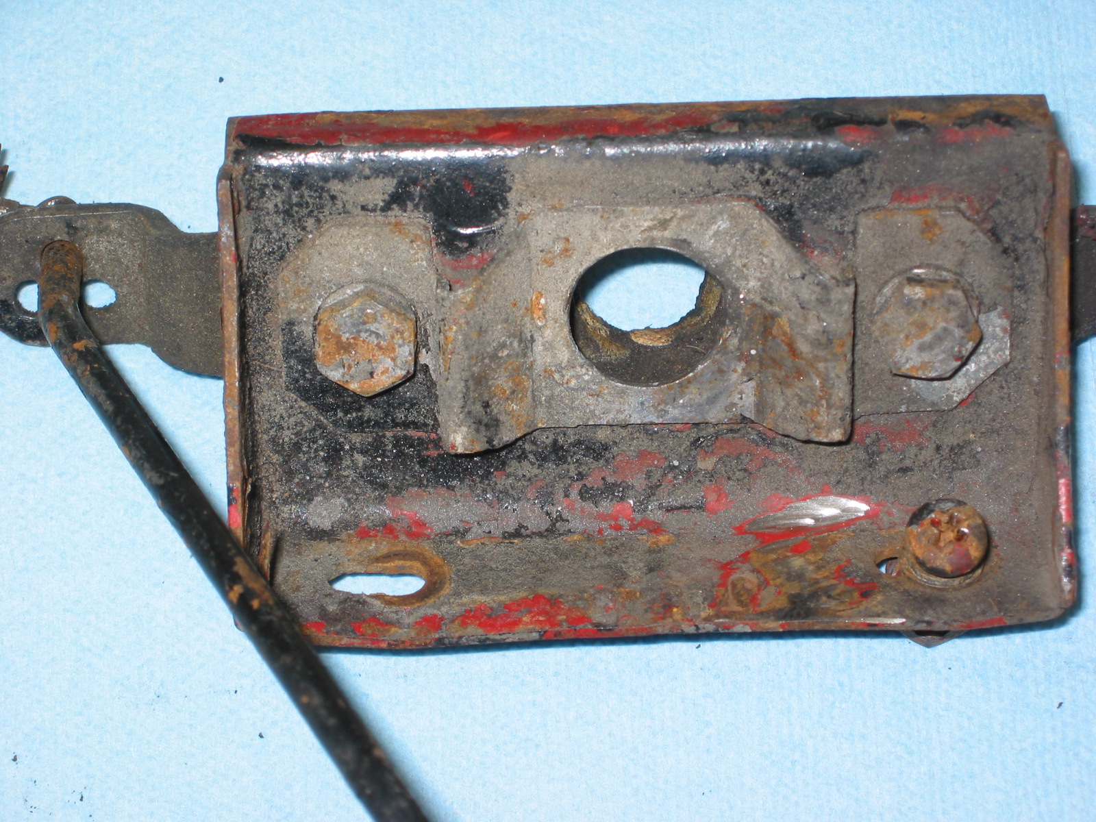
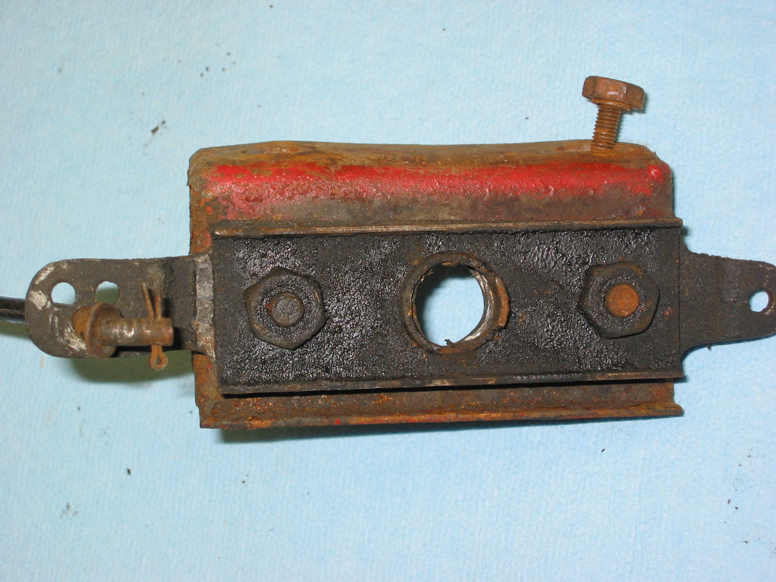
The Bonnet Latch Support Bracket – the mechanism was rusty also, but again, clean up made the parts usable.

Bonnet Latch 3

Bonnet Latch 4
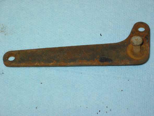
Bonnet Latch Lever

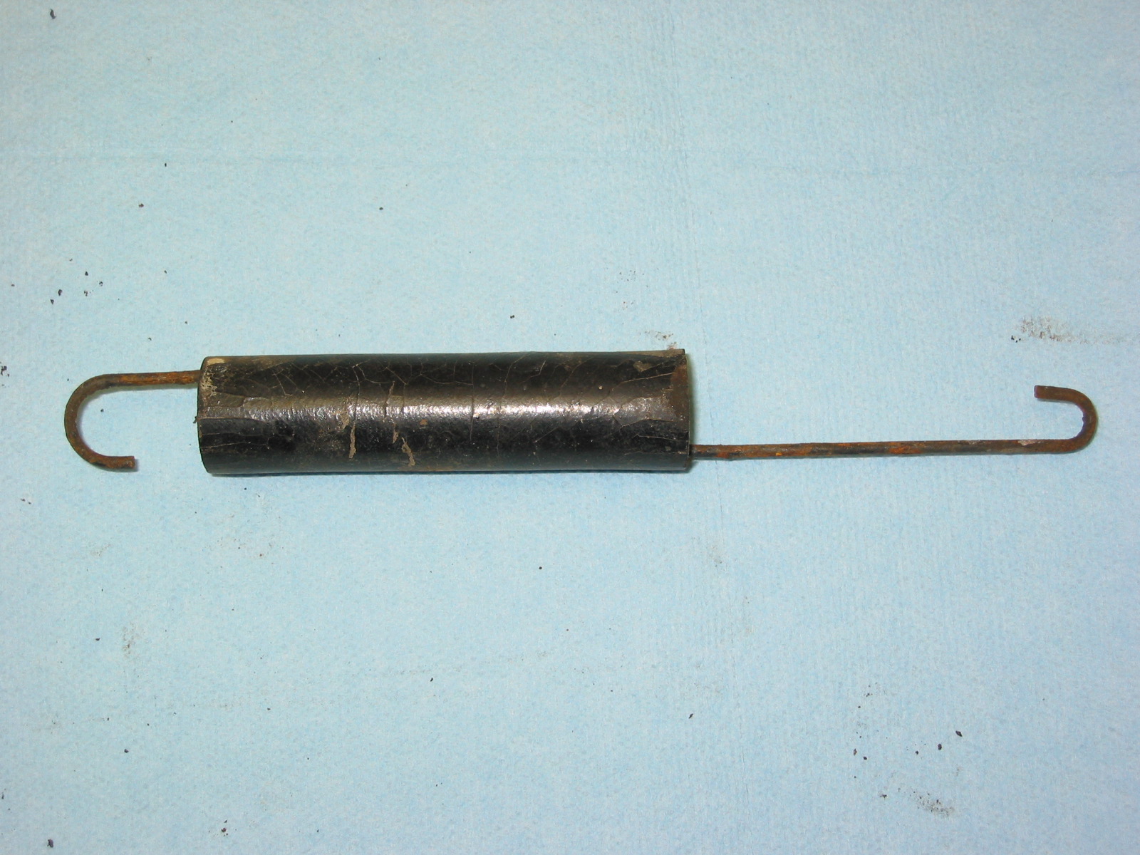
Bonnet Latch Spring & Rubber Tube
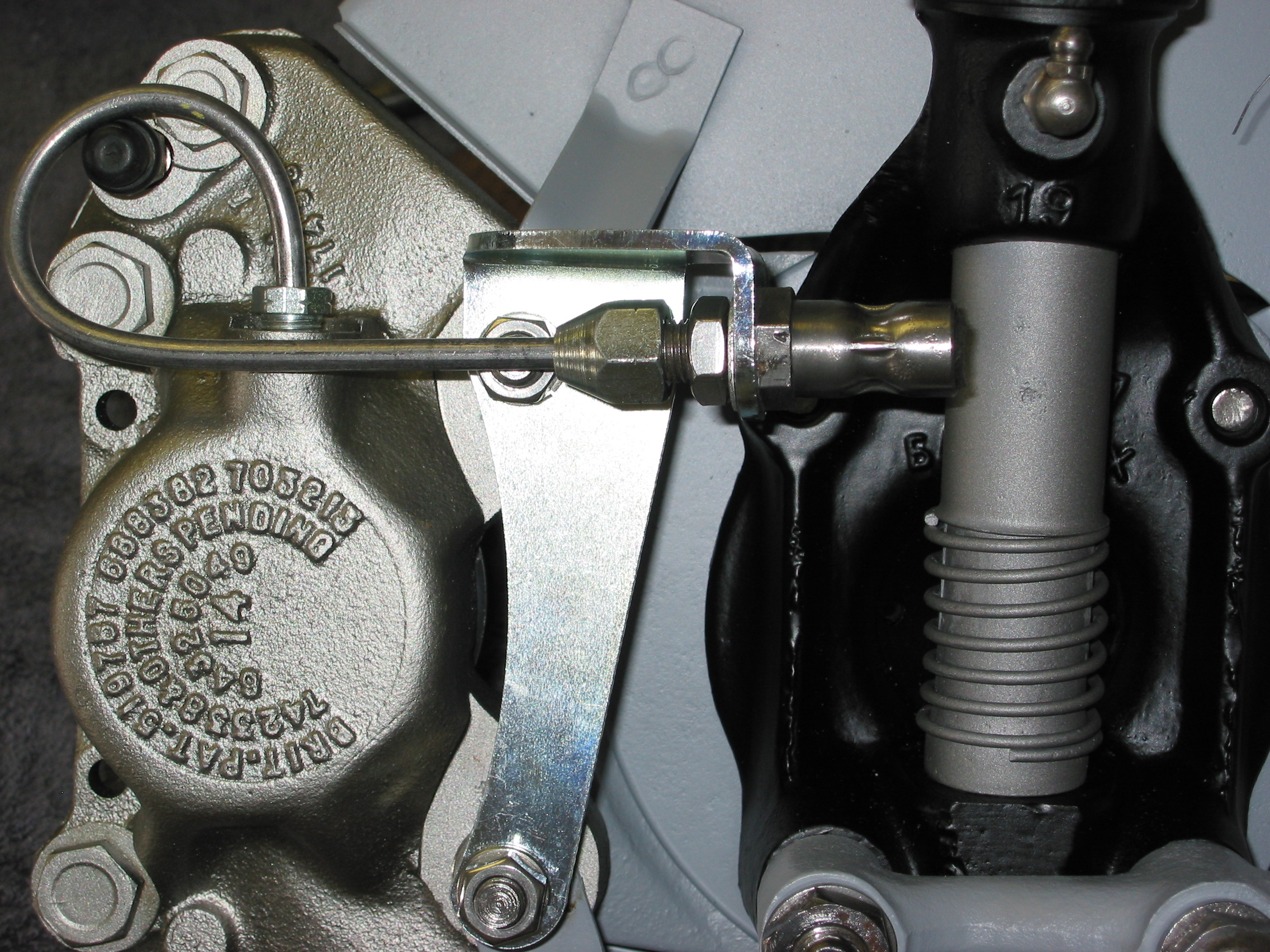
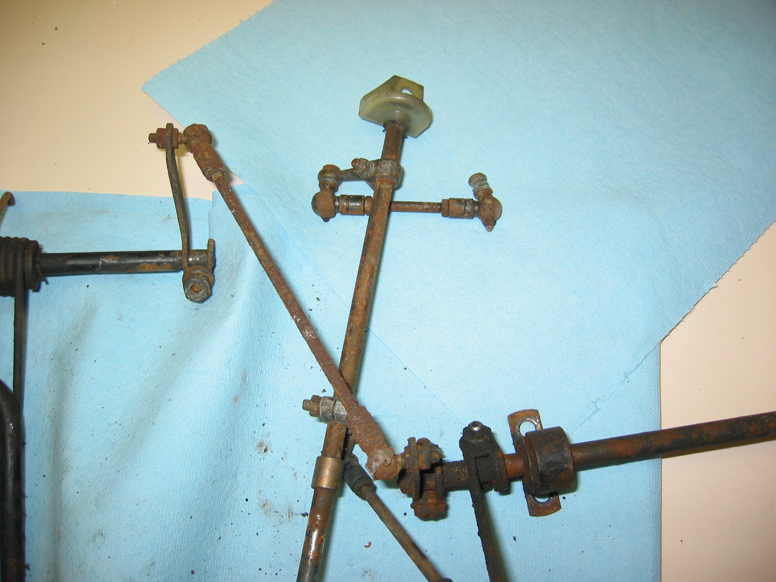
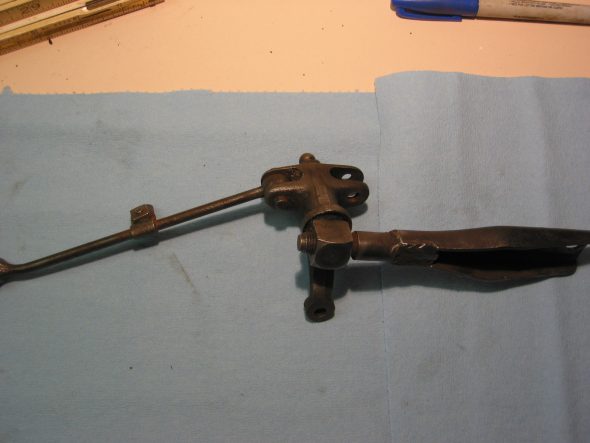
The Throttle Linkage – is also reusable after cleaning, but we will probably replace with new hardware or a contemporary cable system.
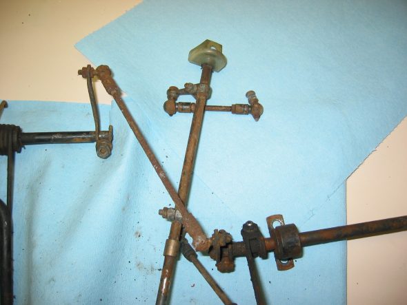
Throttle Linkage 5
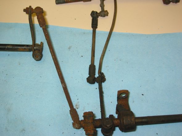
Throttle Linkage 3A
The accelerator pedal – the pedal and bushing and springs looked great. A little clean up and paint and it will be like new.
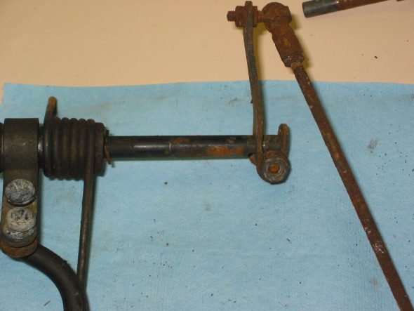
Throttle Linkage 2
Accelerator Pedal

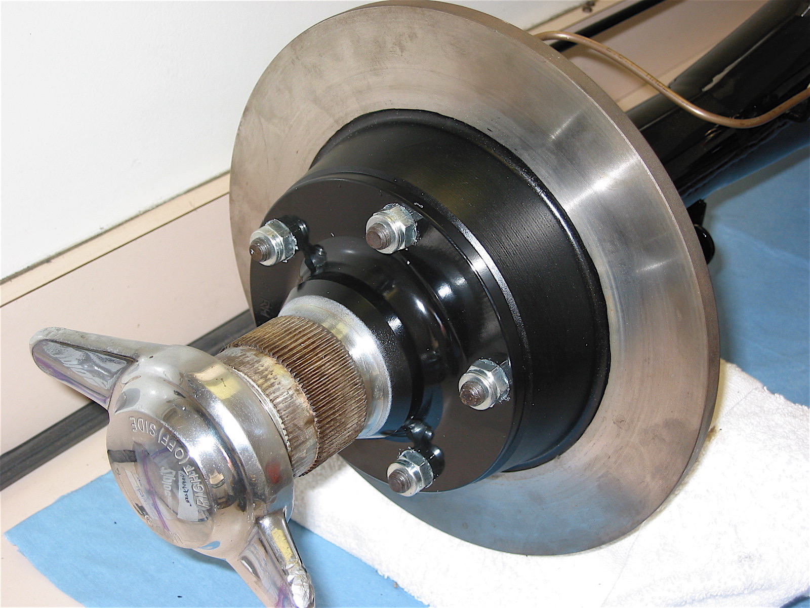
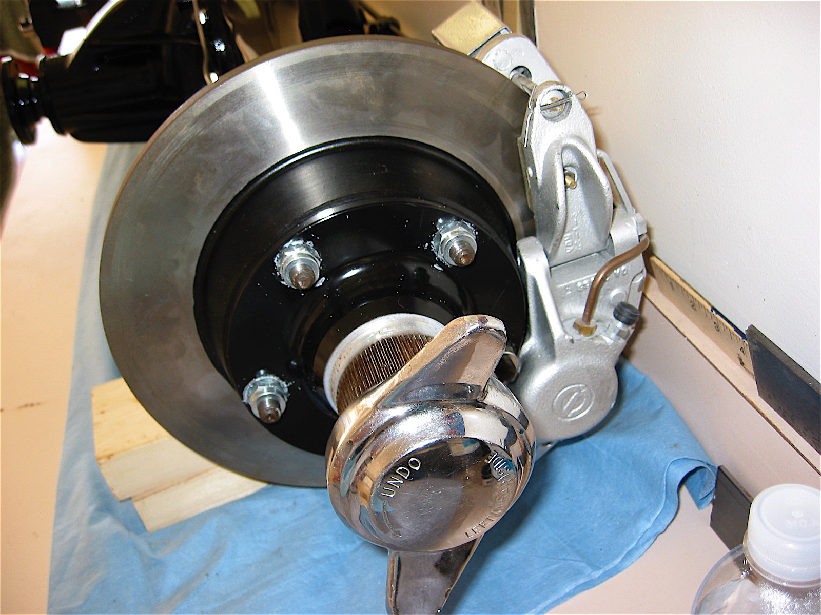
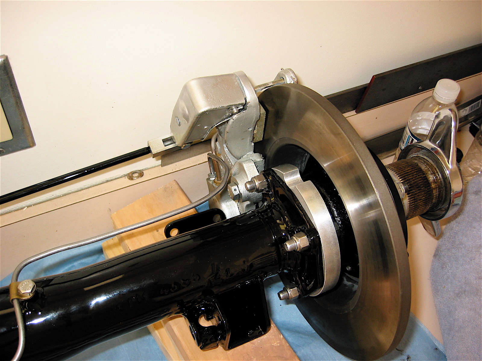
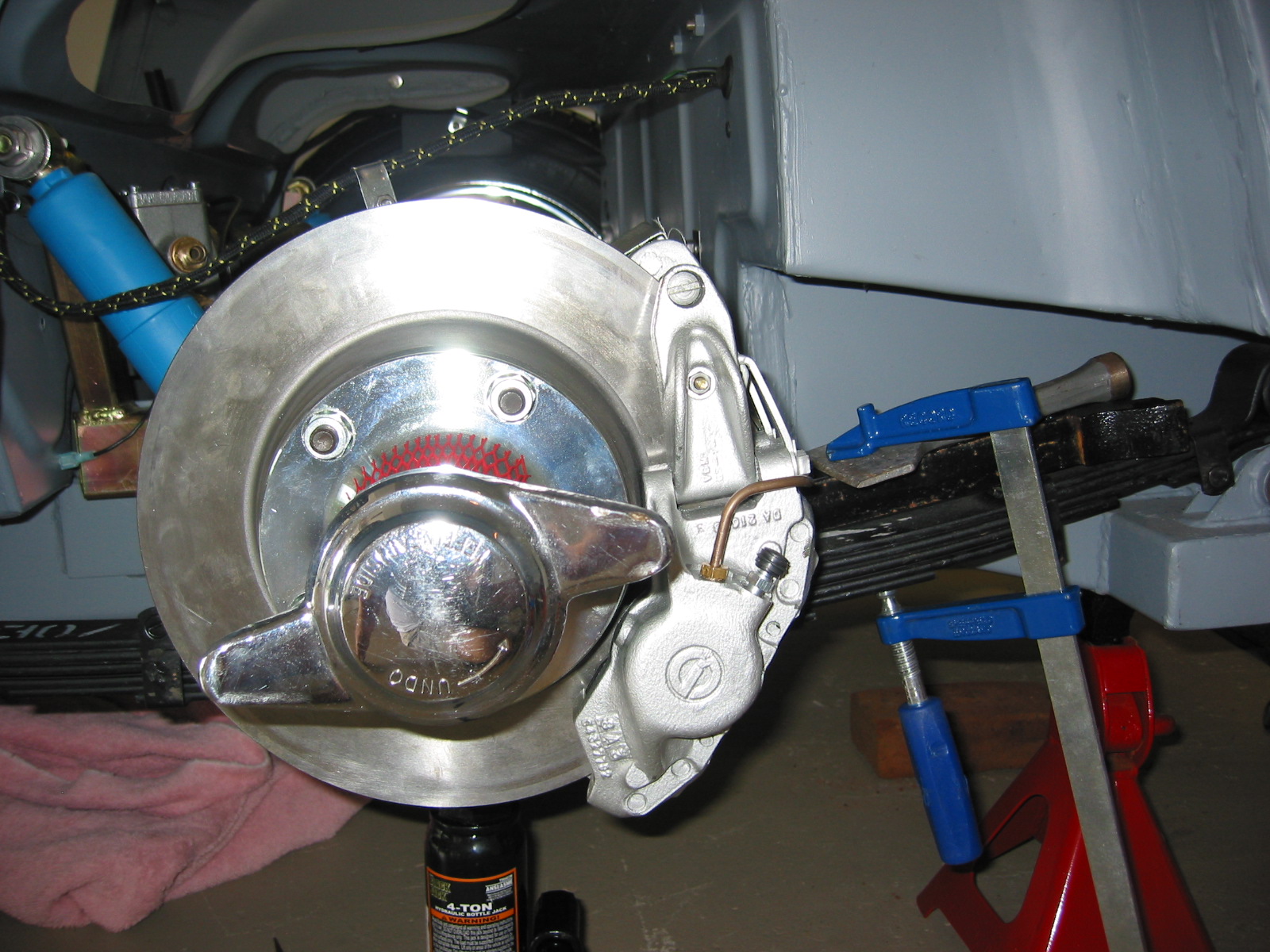
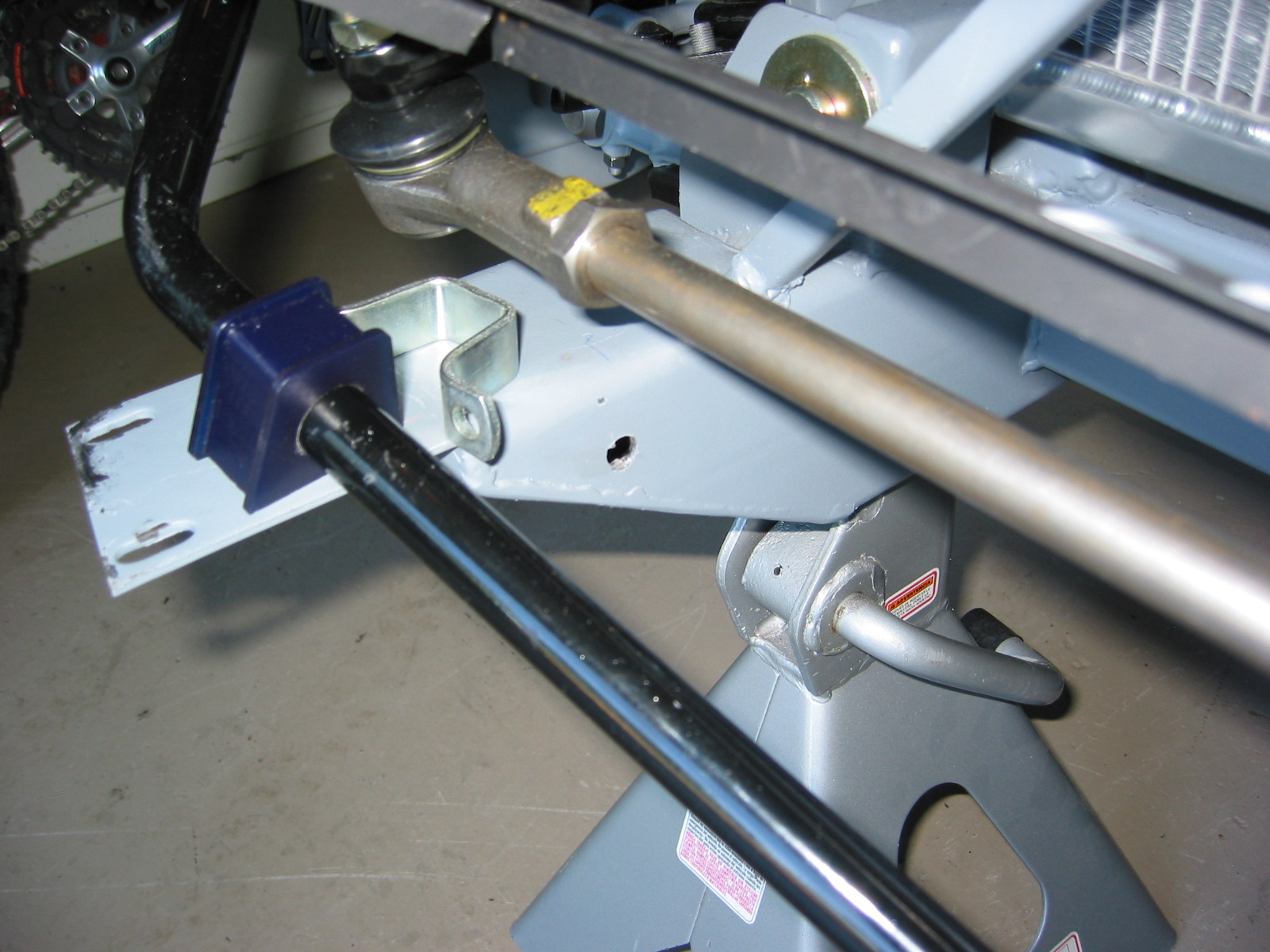
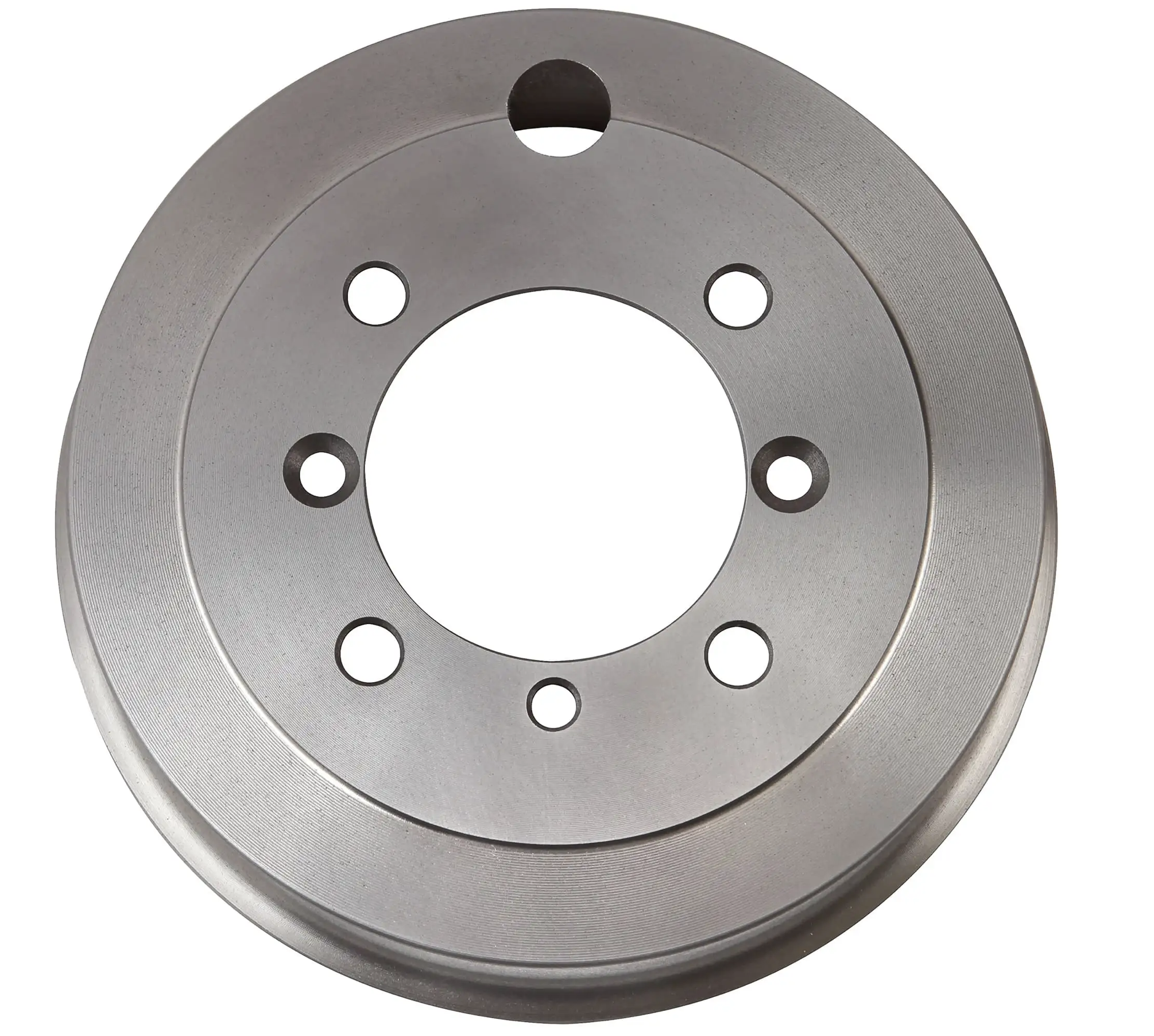 Unfortunately, the new drums rubbed against the backplates just ever so slightly. We visited our friend, Randy Forbes, and he graciously set up his milling machine to remove .0075″ from the back side of each brake drum. We then mounted them on the car and found that we had eliminated the rubbing against the brake back plates, but we still had the dreaded wobble on the RH wheel.