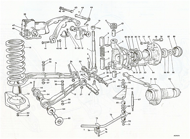
The Original Front Suspension
The front suspension used coil springs, a 5/8” anti-sway bar, rubber bushings and Armstrong lever shocks.
Front Suspension Modifications
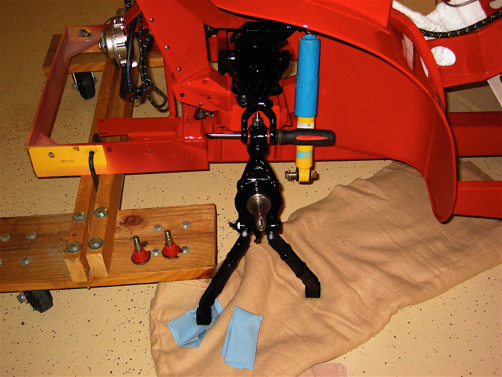
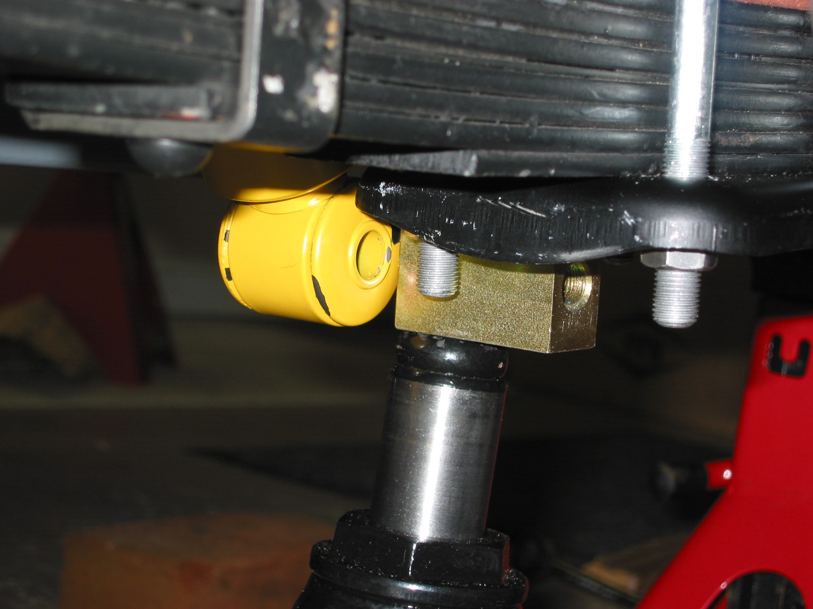
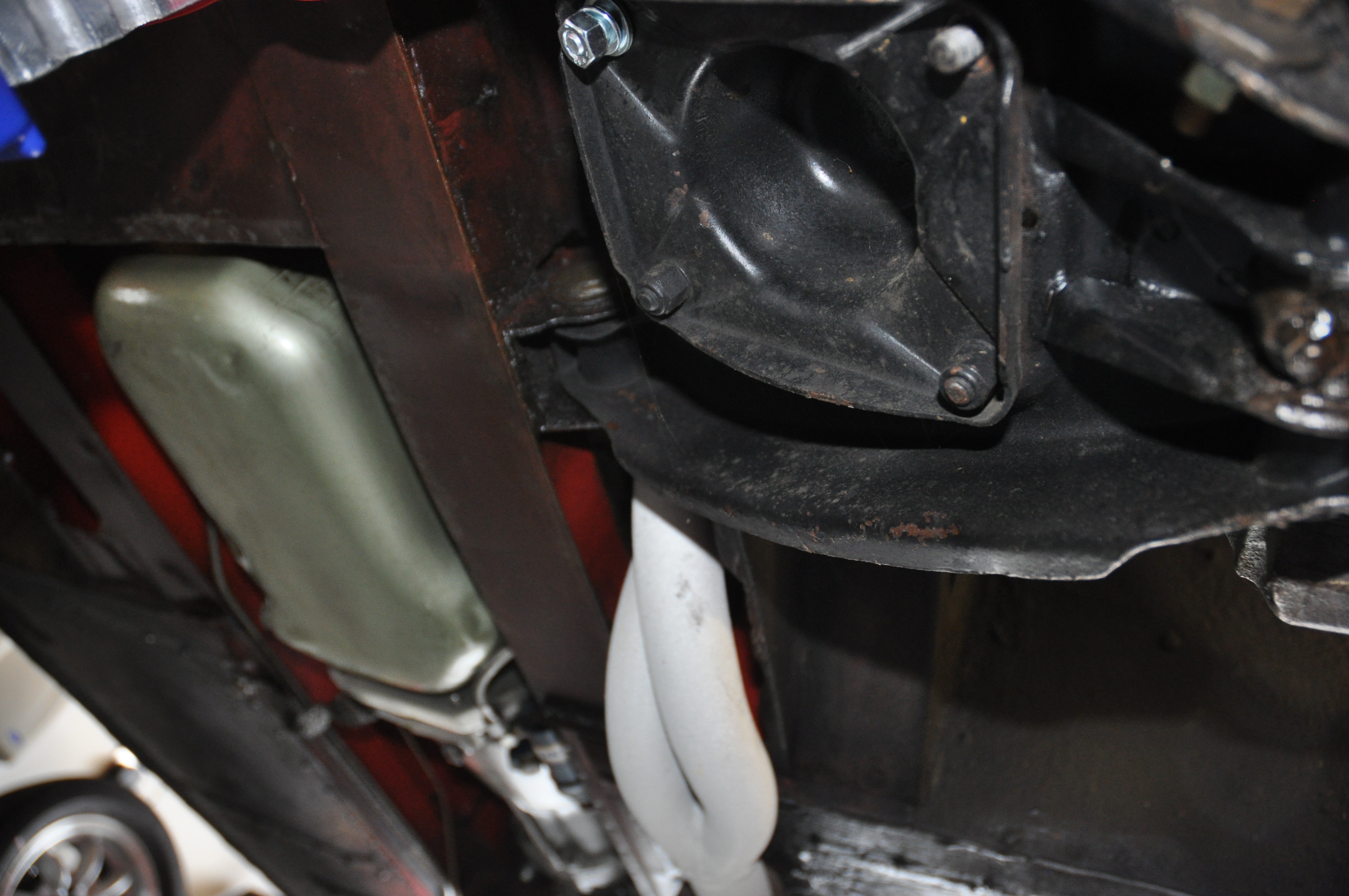
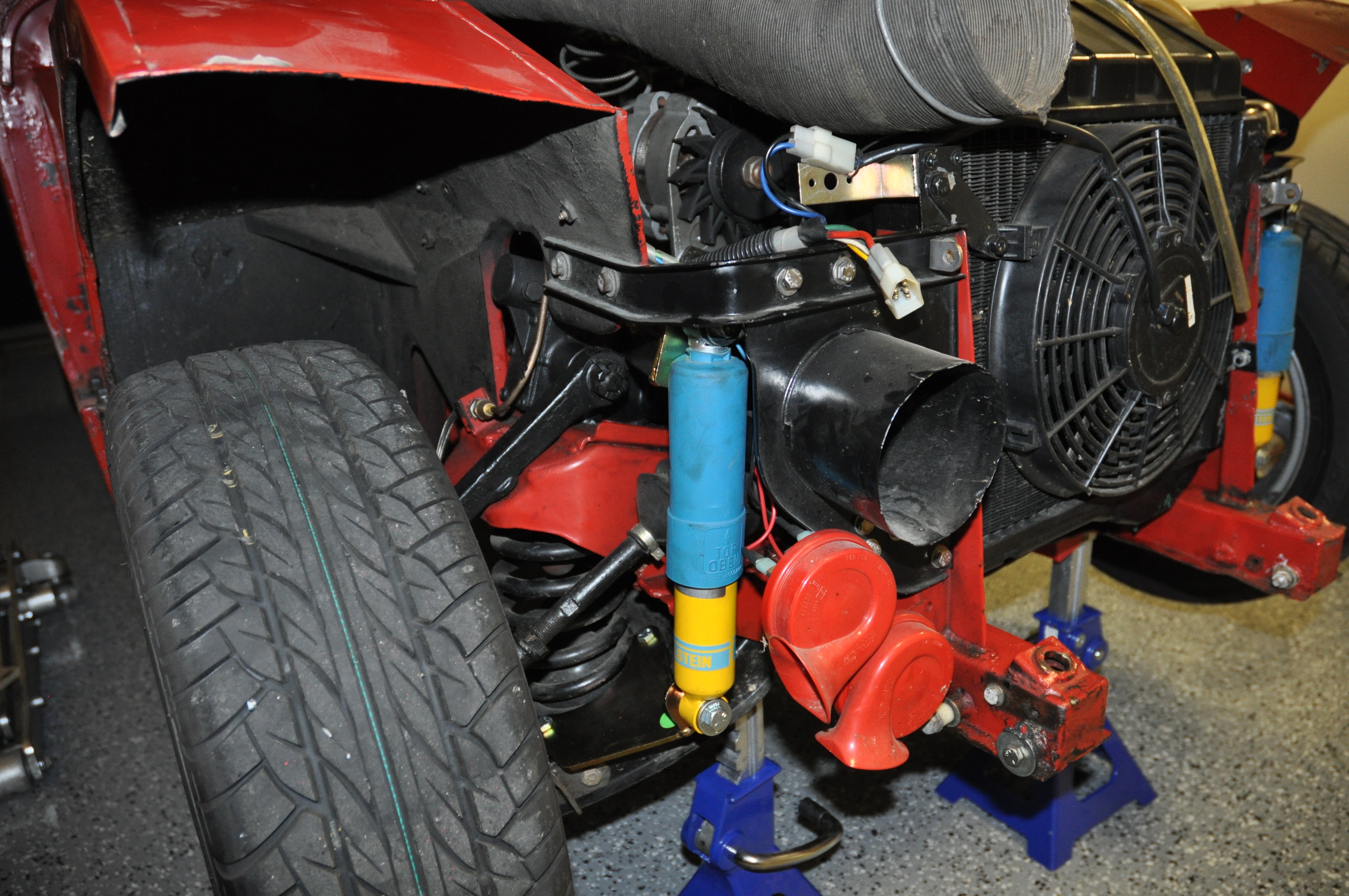
Tube Shocks
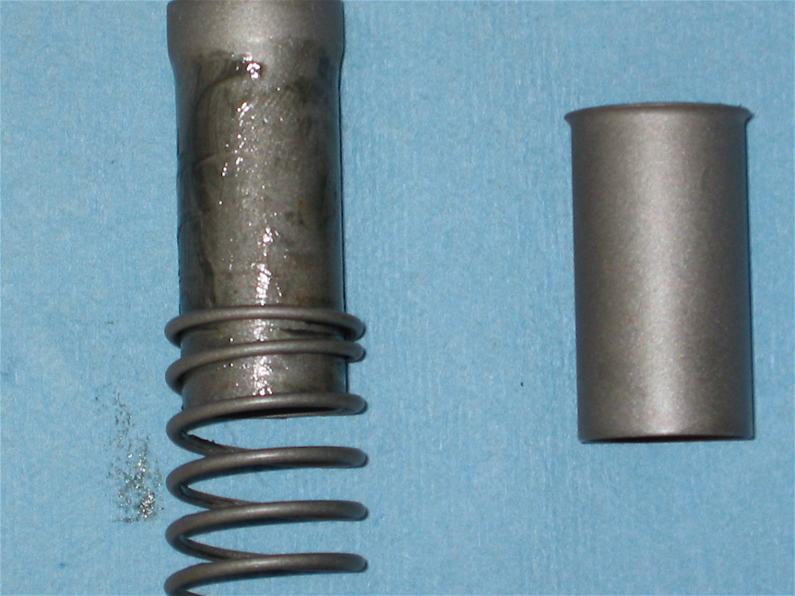
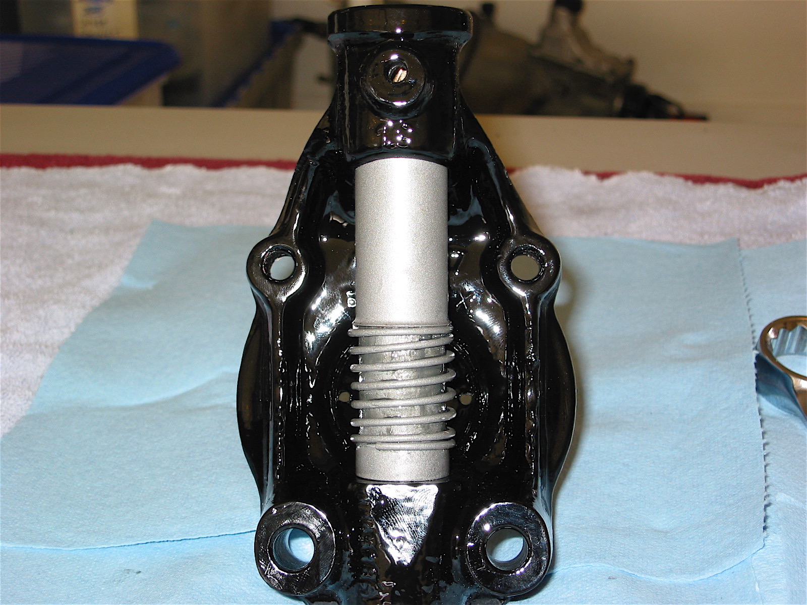
I had the front shocks rebuilt by World Wide Auto Parts http://www.nosimport.com/, but decided to install Bilstein Tube shocks supplied in Udo Putzke’s Fahrspass http://www.putzkes-fahrspass.com/Eng/kits.html Tube Shock Kit. I ave been very pleased with the performance of the shocks. This is a document describing the installation: Putzkes Fahrspass Tube Shock Kit.

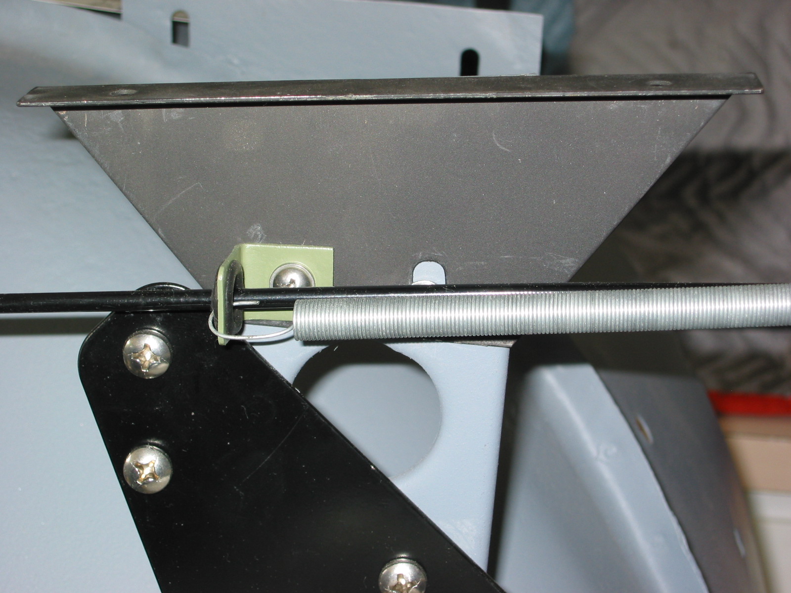
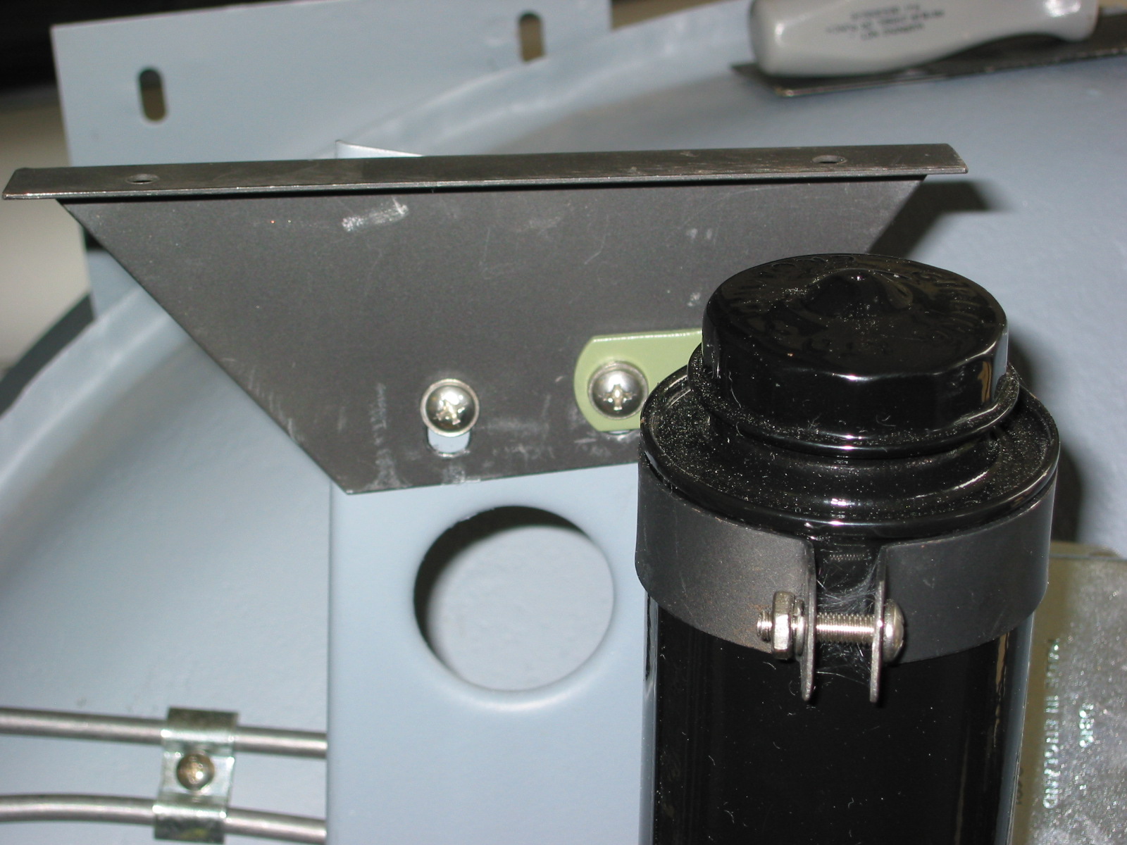
Blistein Tube Shocks
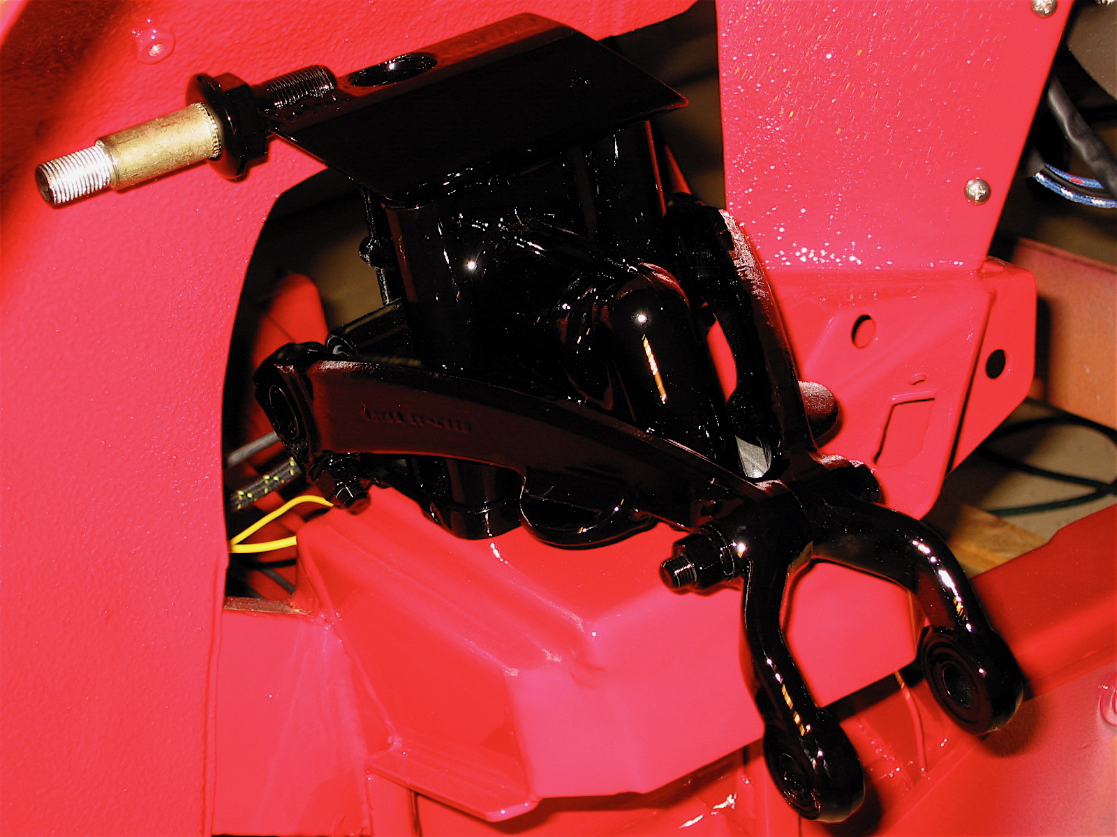
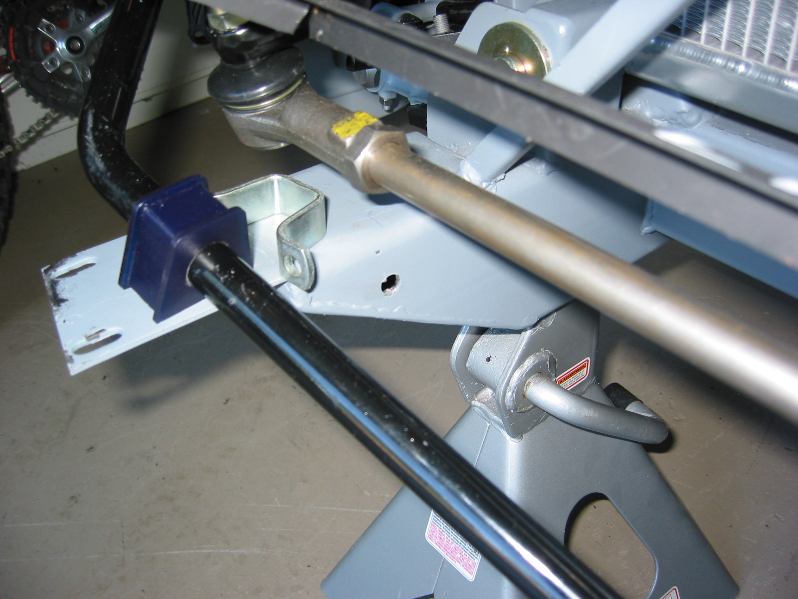
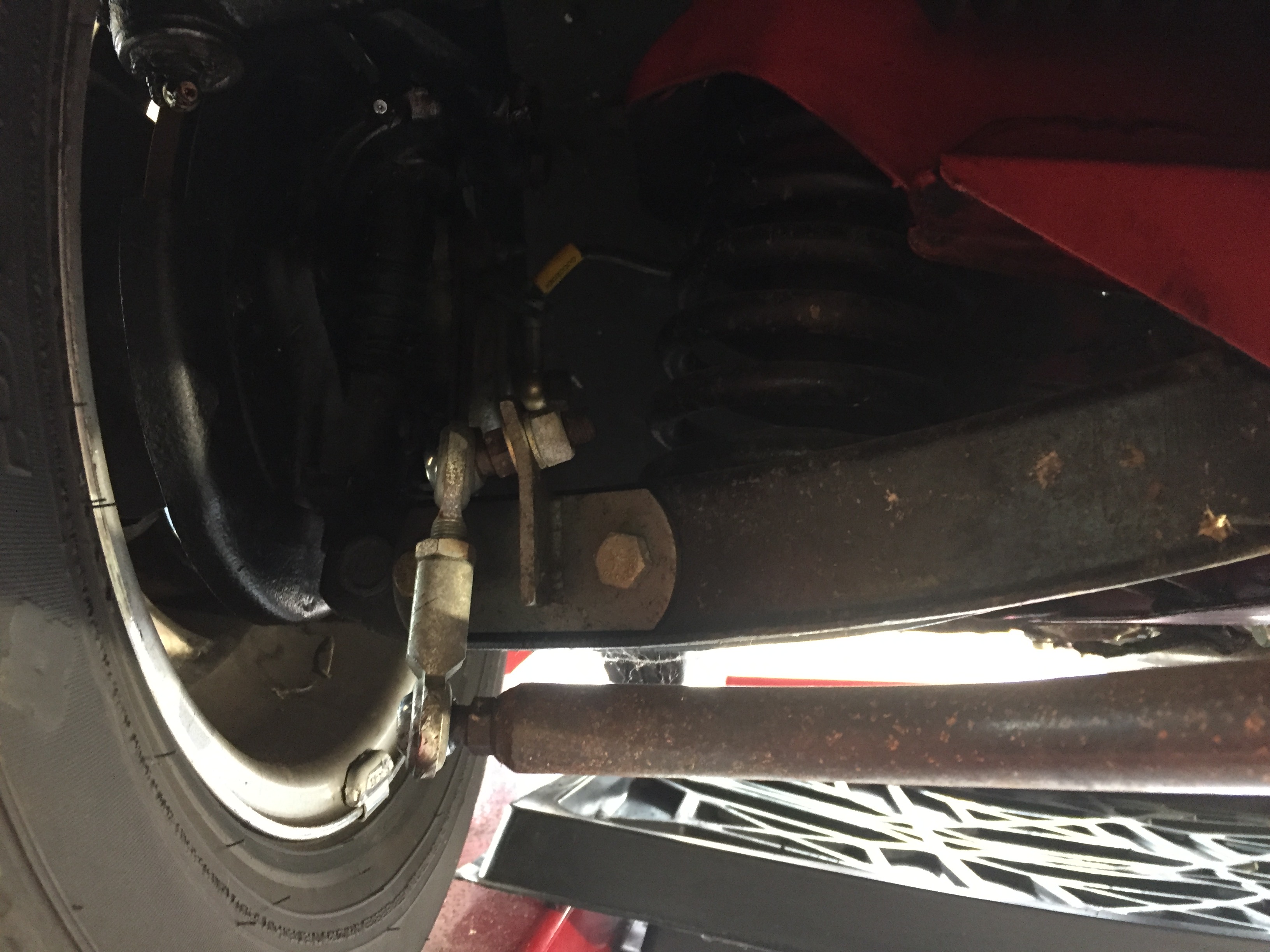
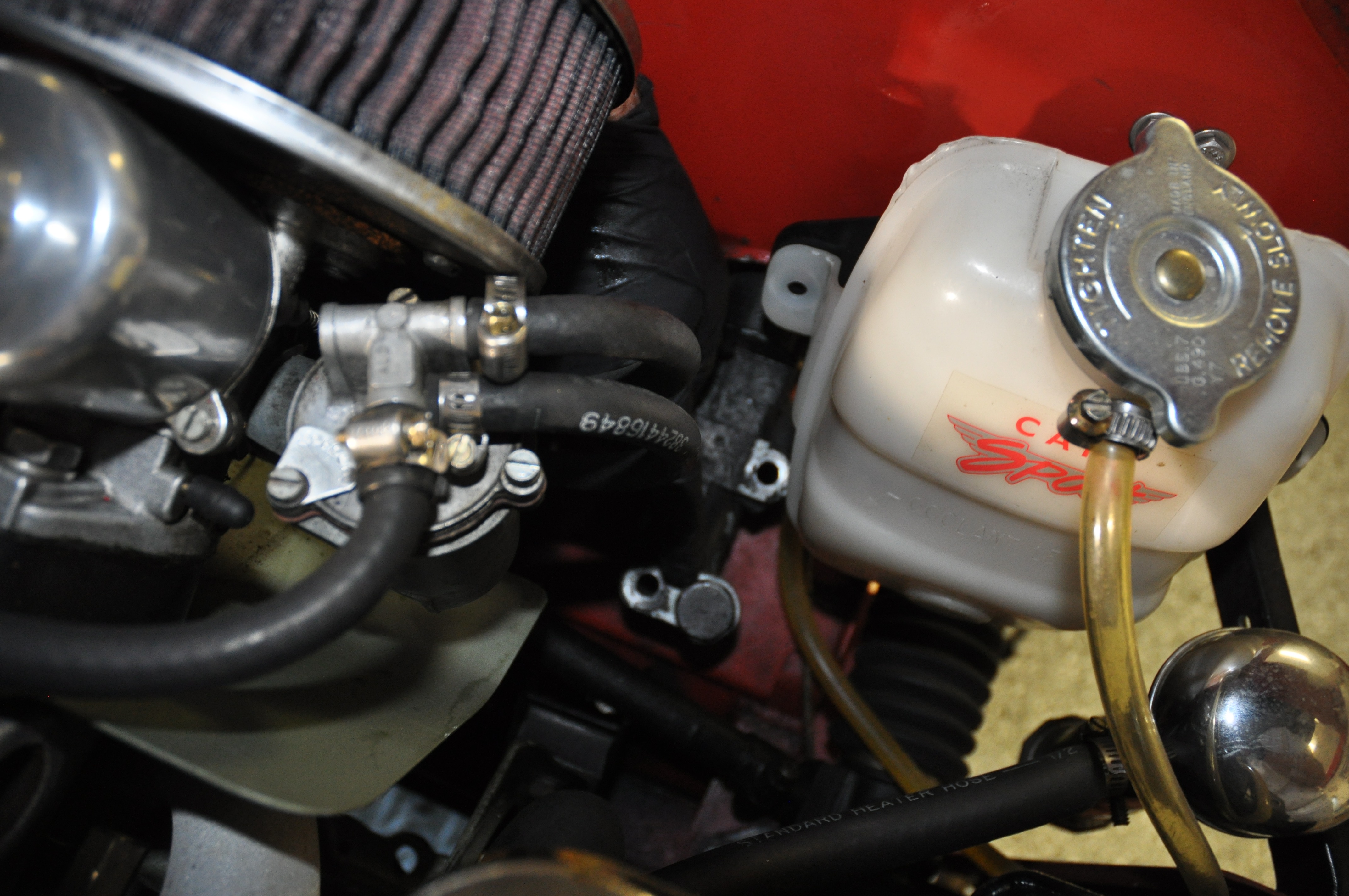
Anti-sway Bar
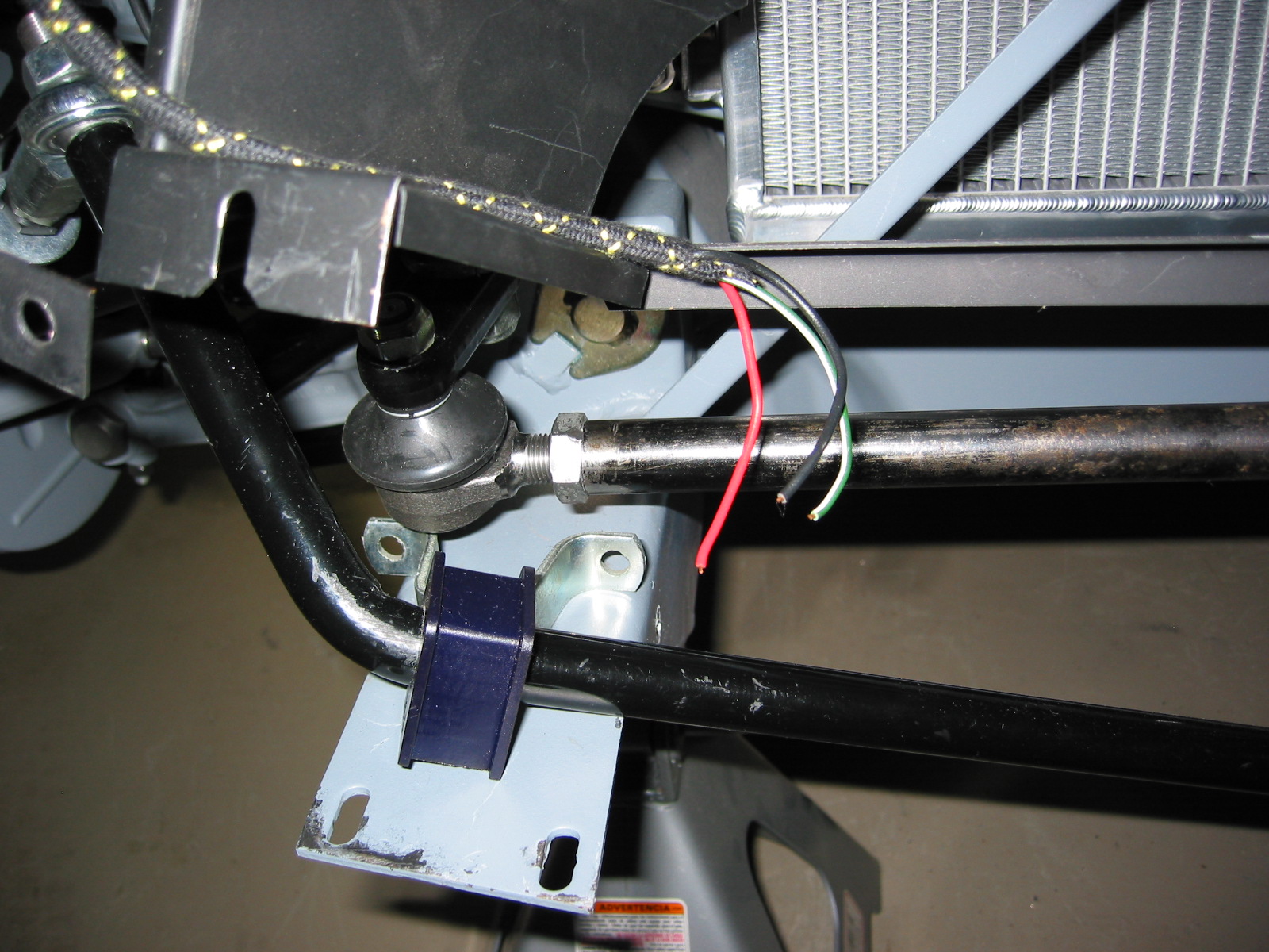
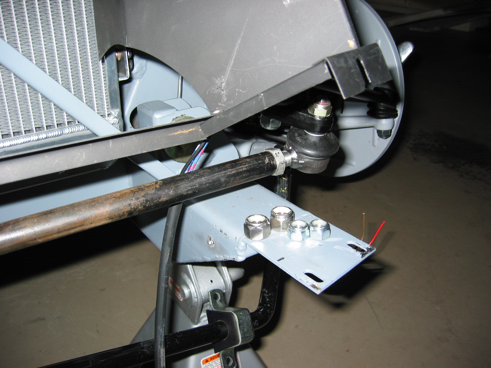
I replaced the standard 5/8″ bar with a heavy duty 7/8″ sway bar with poly bushing and rose joint links sourced from Cape International. http://www.cape-international.com/

Anti-Sway Bar
Poly Bushings
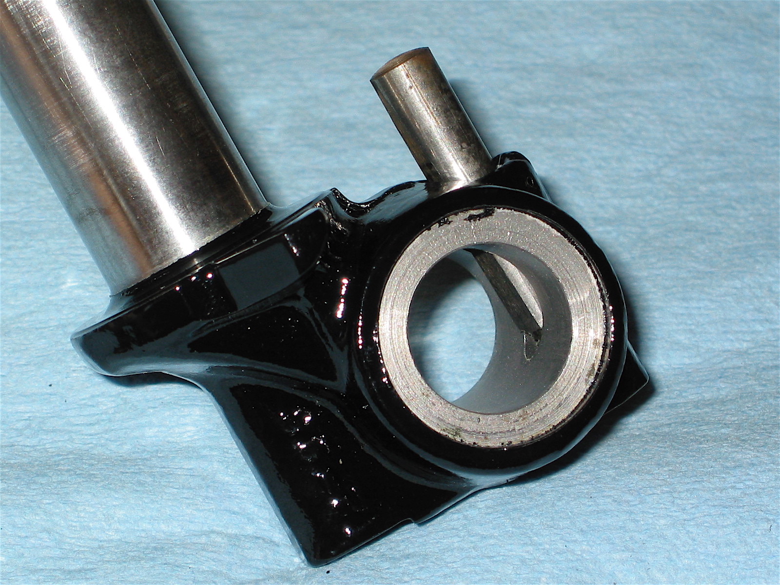
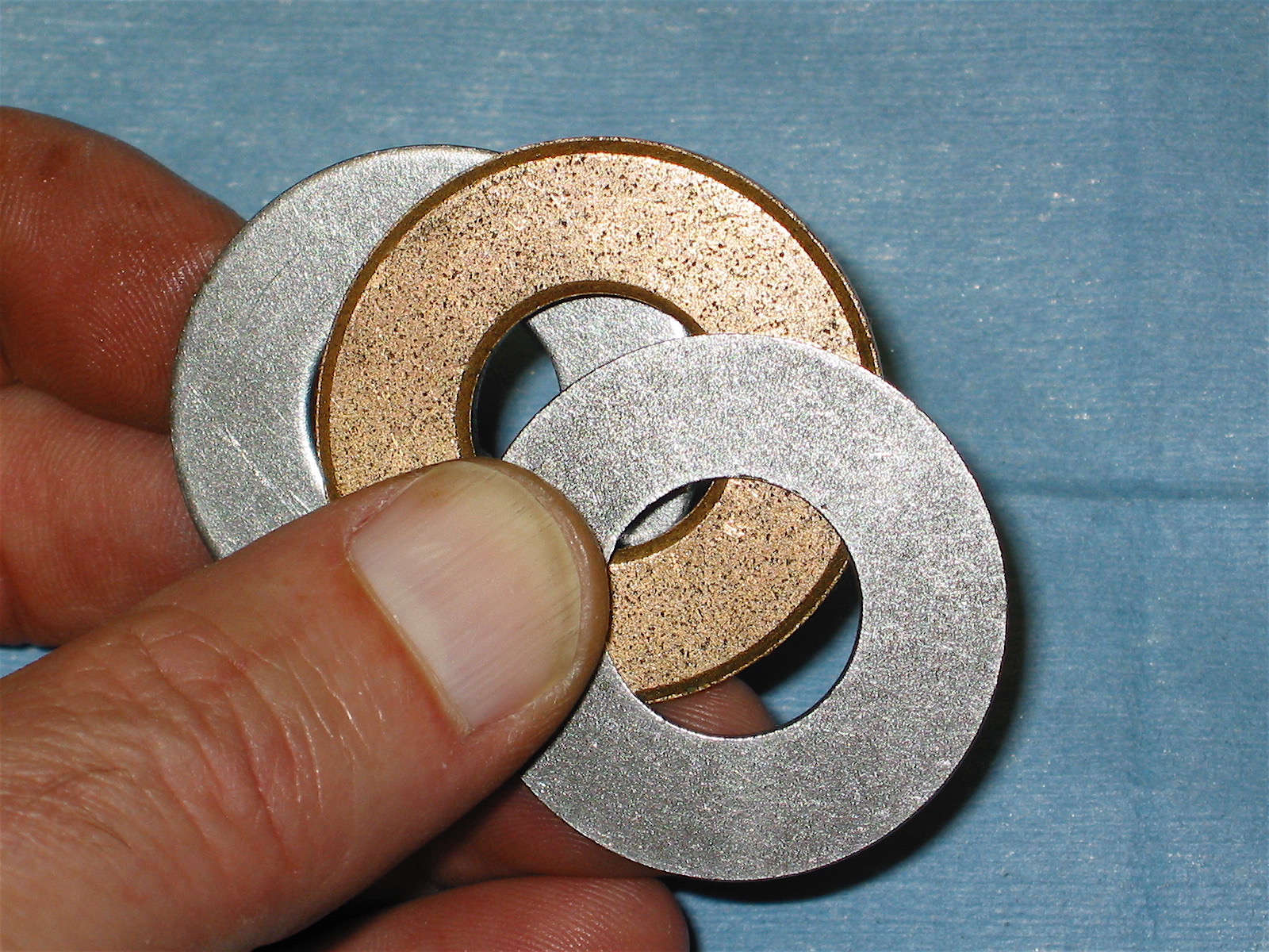
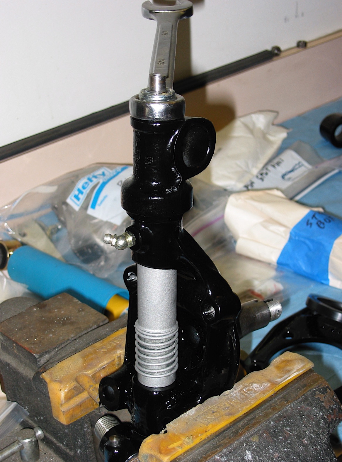
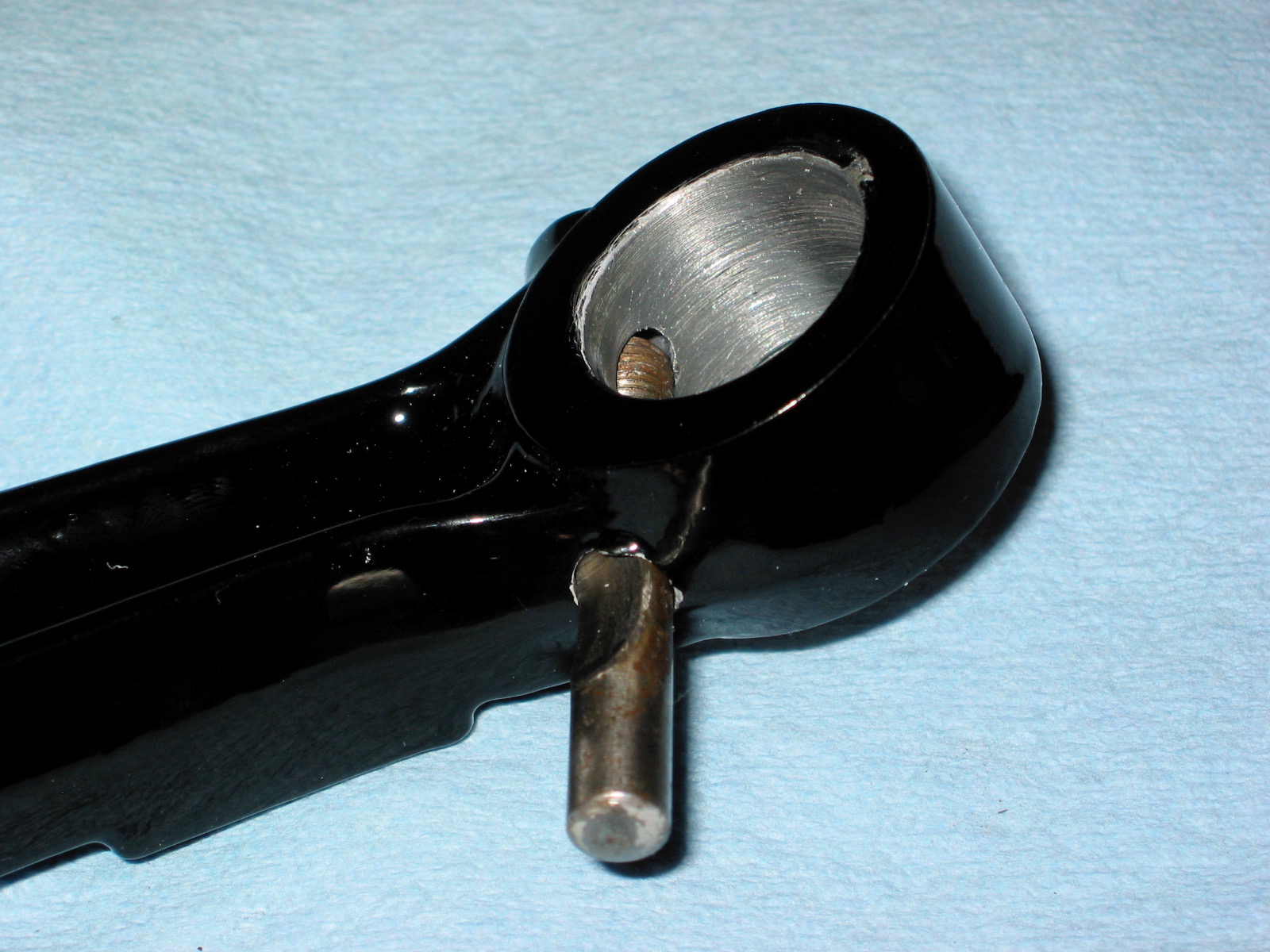
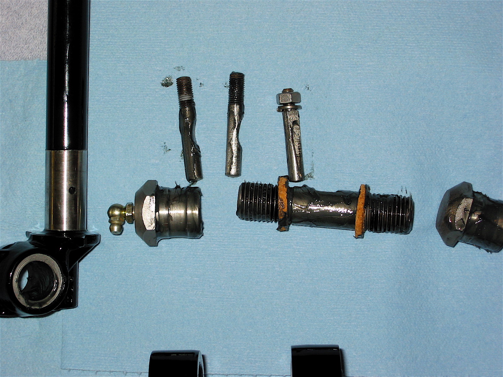
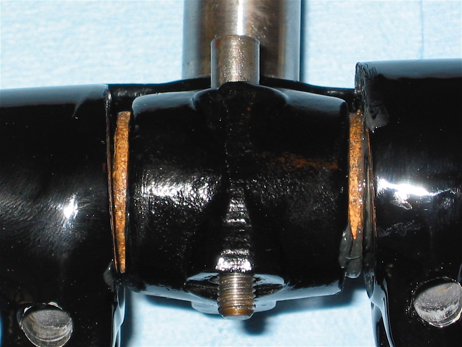
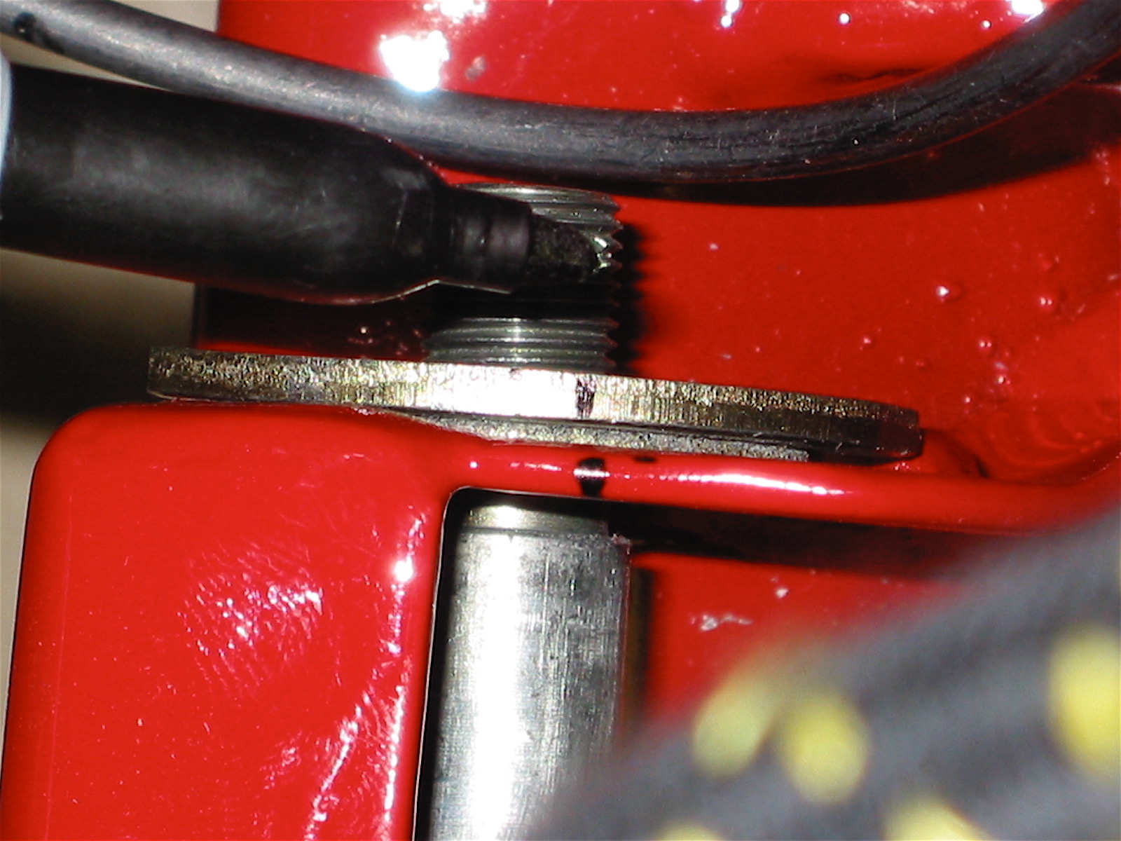
All of the front suspension rubber bushings were replaced with poly bushings purchased from Putzke’s Fahrspass http://www.putzkes-fahrspass.com/Eng/BigHealey_poly_page.htm Lubricating poly bushes is important. The image below illustrates the proper lubricating surfaces.

Putzke’s poly bush lubrication
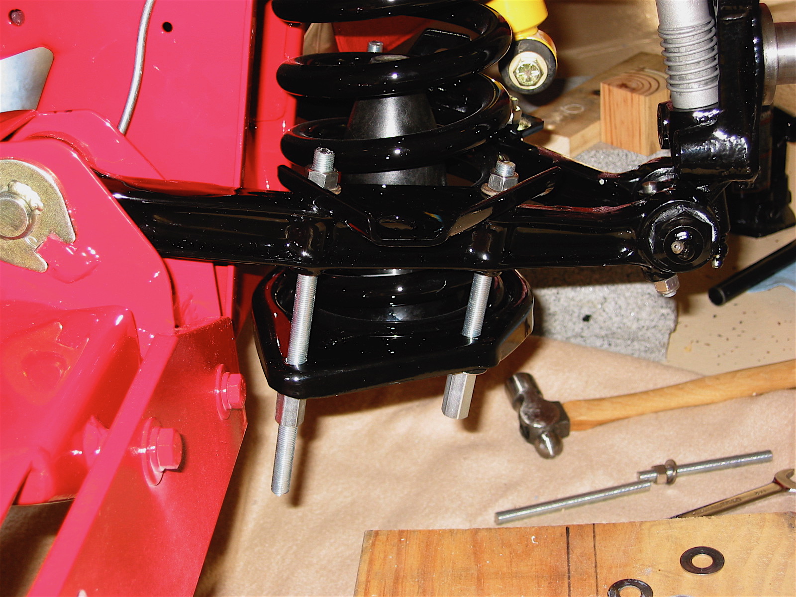
Coil Springs
At the recommendation of others, I replaced the BT7 springs with springs from the BJ8.
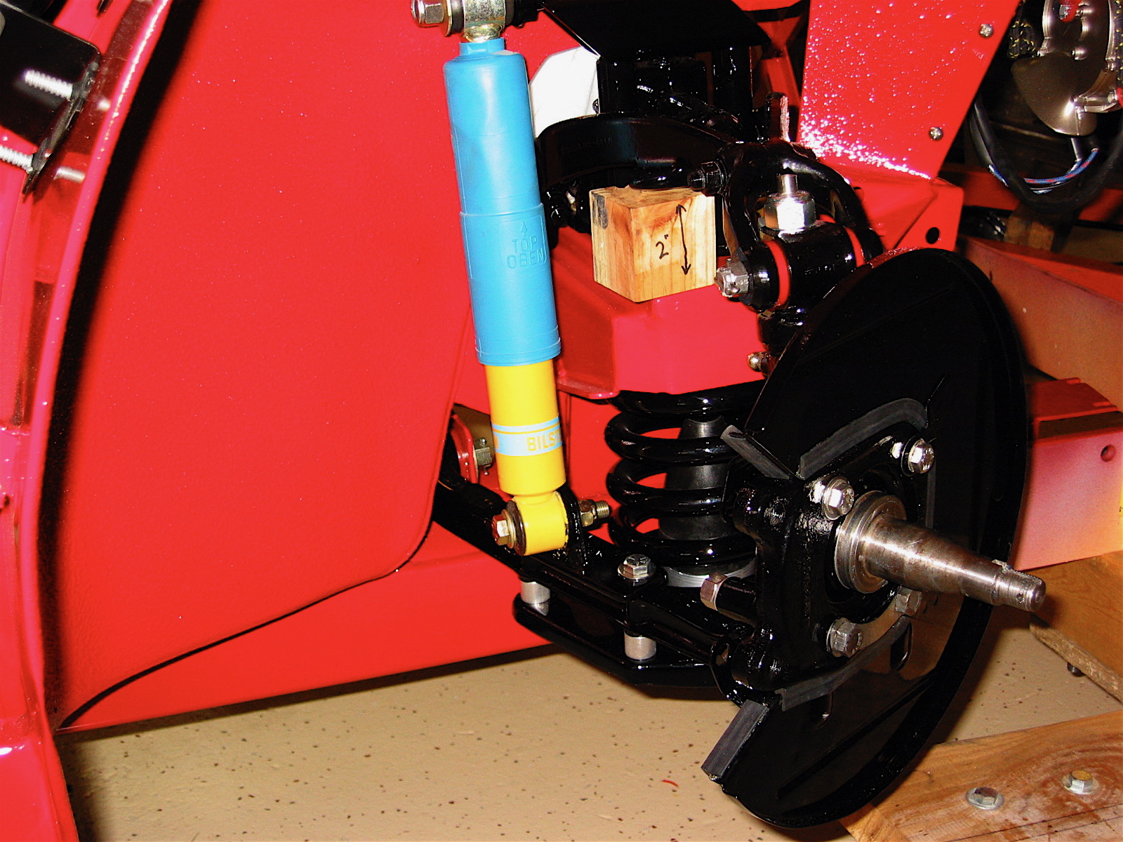
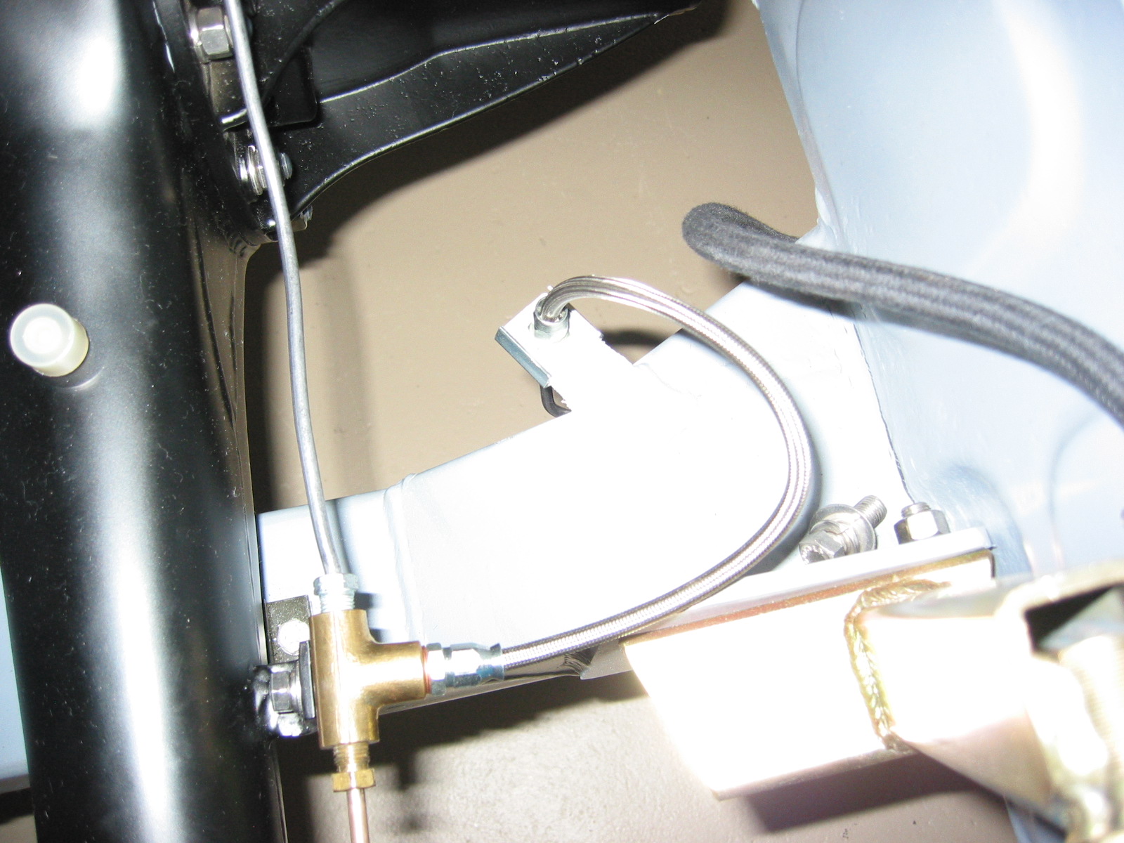
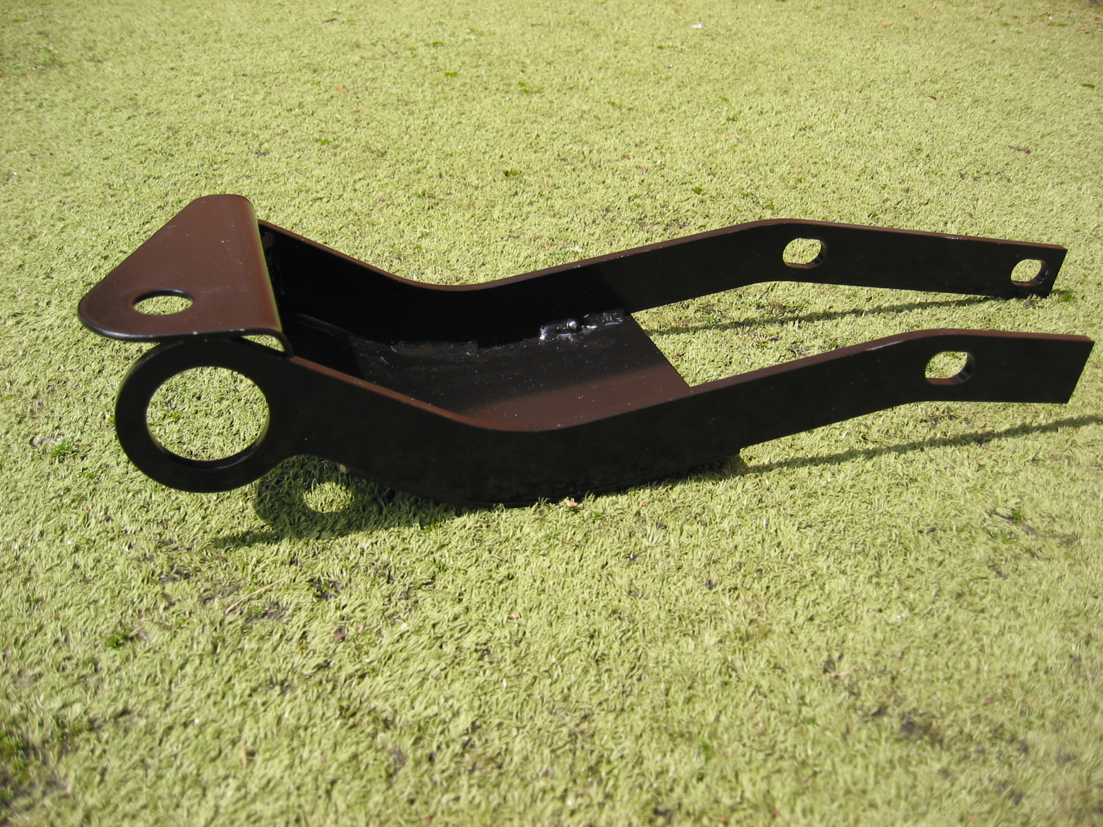
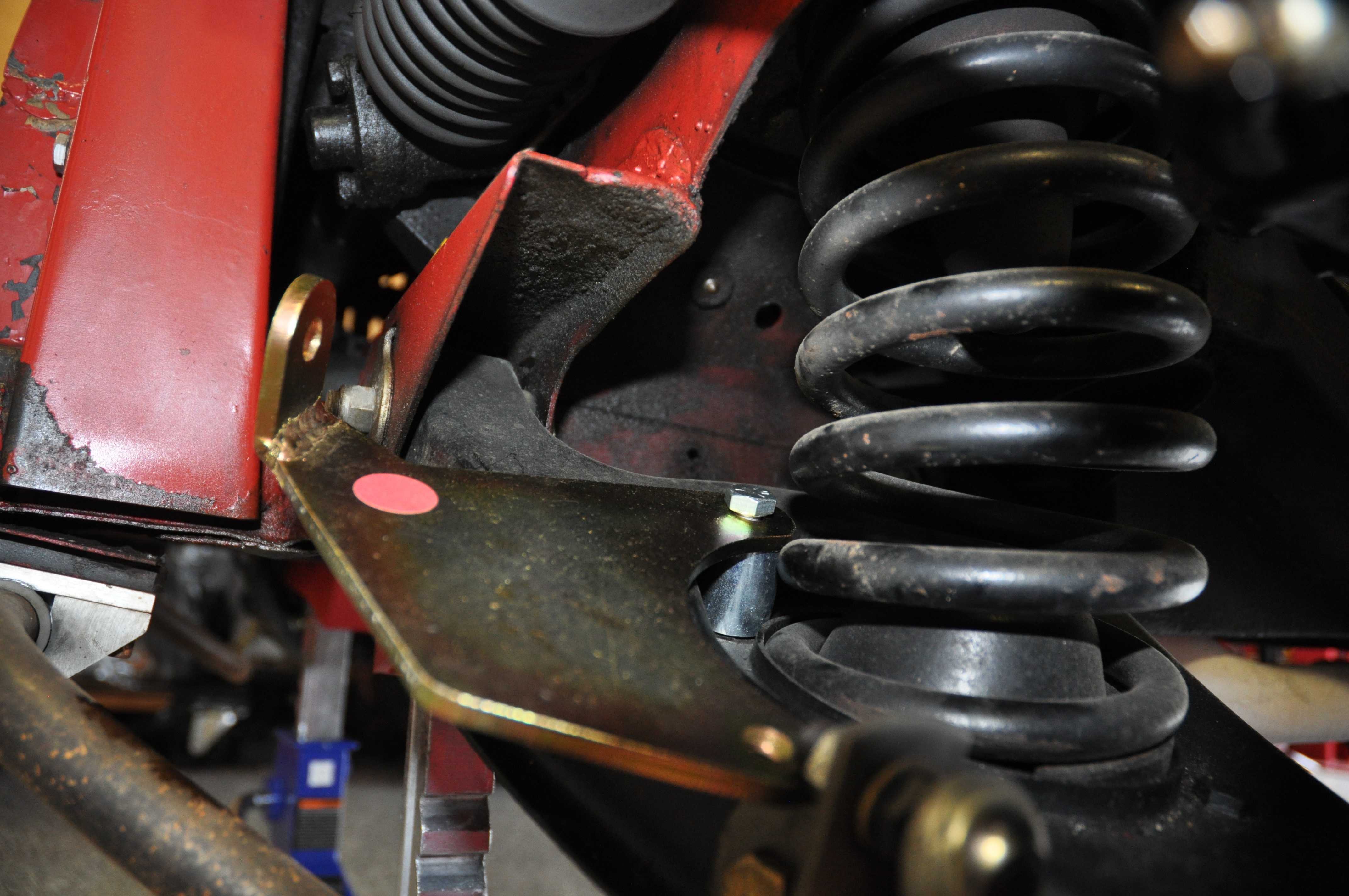
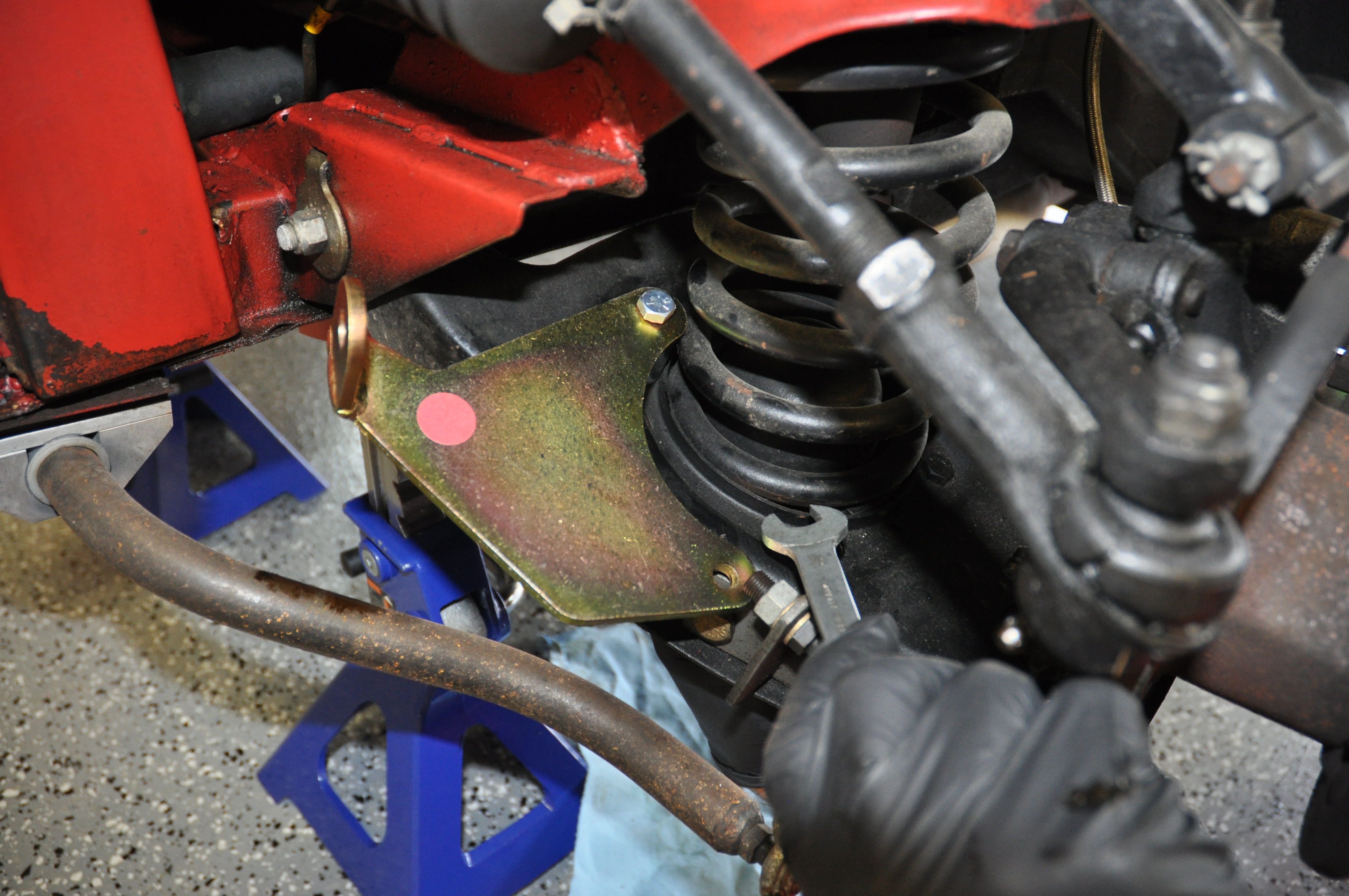
Front Lowering Kit
I like a slightly more aggressive look accomplished by lowering the front end so I purchased a lowering kit from Denis Welch Motorsport http://www.bighealey.co.uk/content/lowering-kit. When you lower the front end it is also necessary to add a spacer to the rubber bump stop. This was also sourced from Denis Welch http://www.bighealey.co.uk/content/bump-stop-spacers-and-tube-nuts.

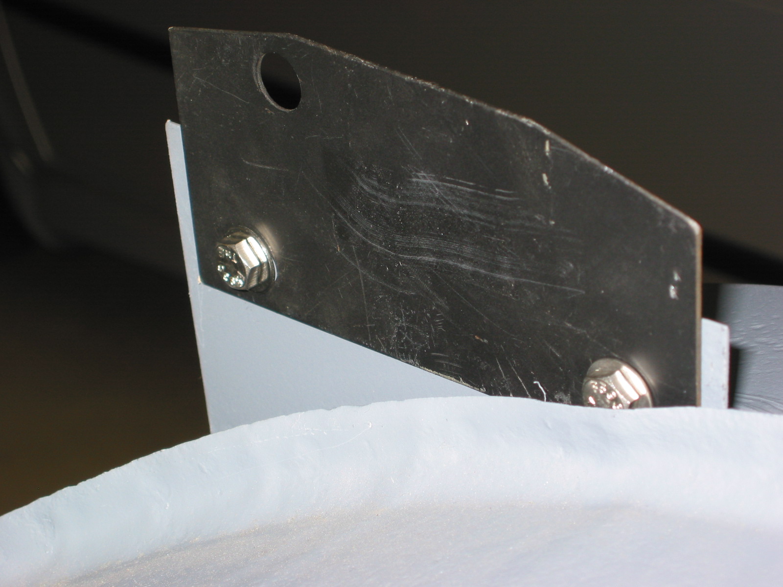
Lowering Kit
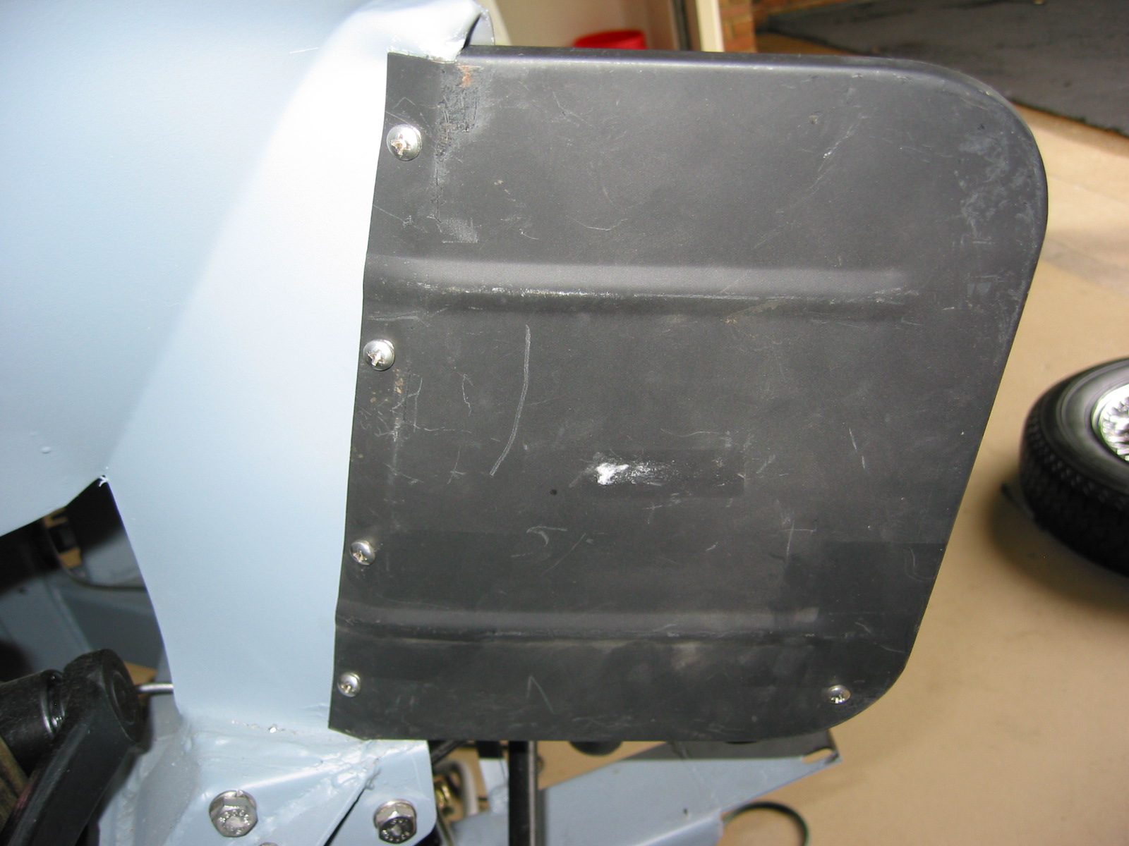
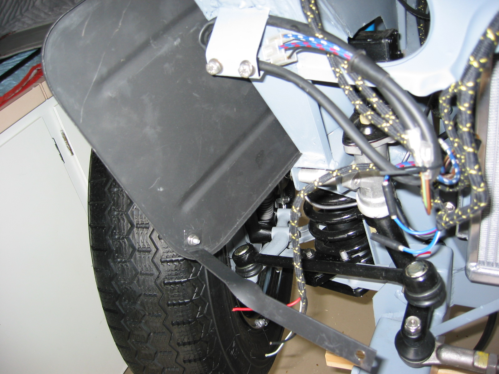
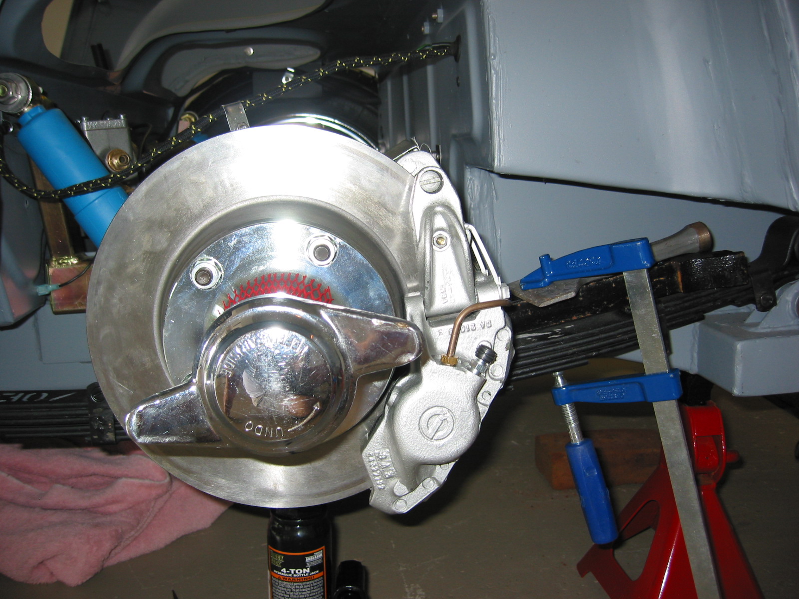
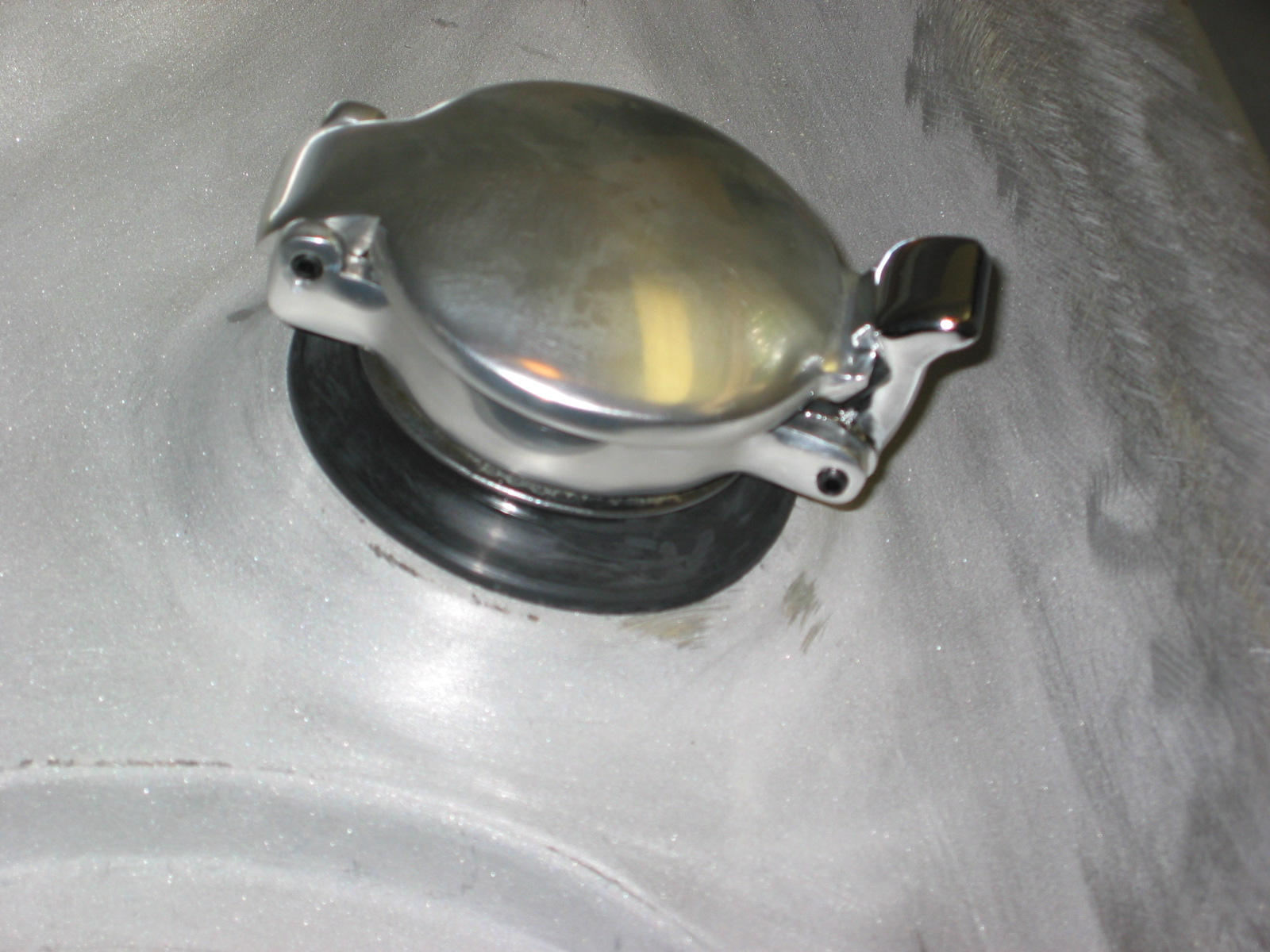
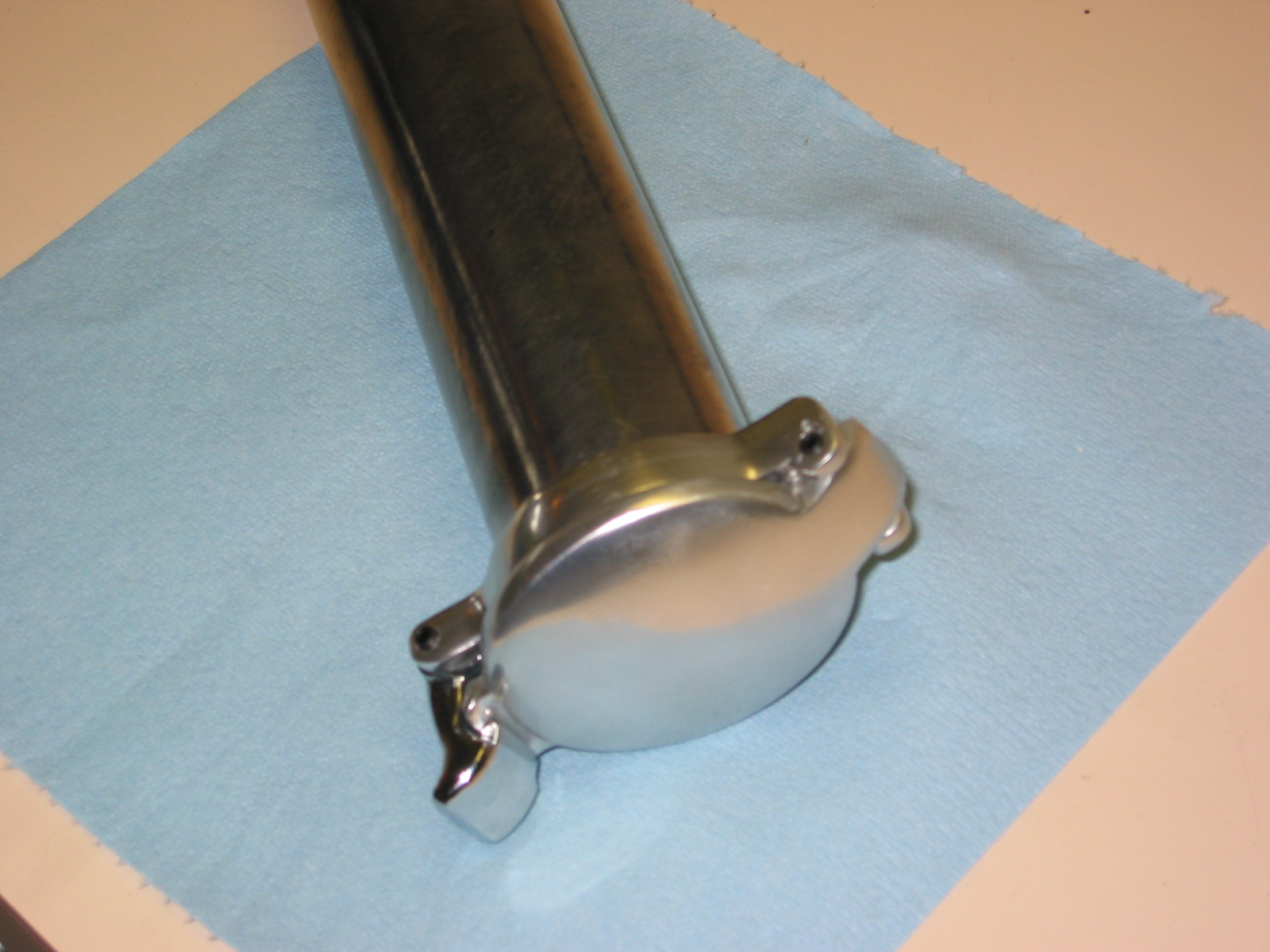
Ball Joint Dust Covers
Rubber components in today’s restoration world are often very poor quality. Someone on the Healey list serve discovered that Hyundai ball joint covers, past #56828-21010, are of superior quality to that available for the Healey. I ordered and used them and they worked perfectly!

Tie Rod Dust Seals
Original Rear Suspension/Axle
Semielliptic leaf springs, solid axle with transverse panhard rod, 3.909 rear differential
Rear Suspension/Axle Modifications
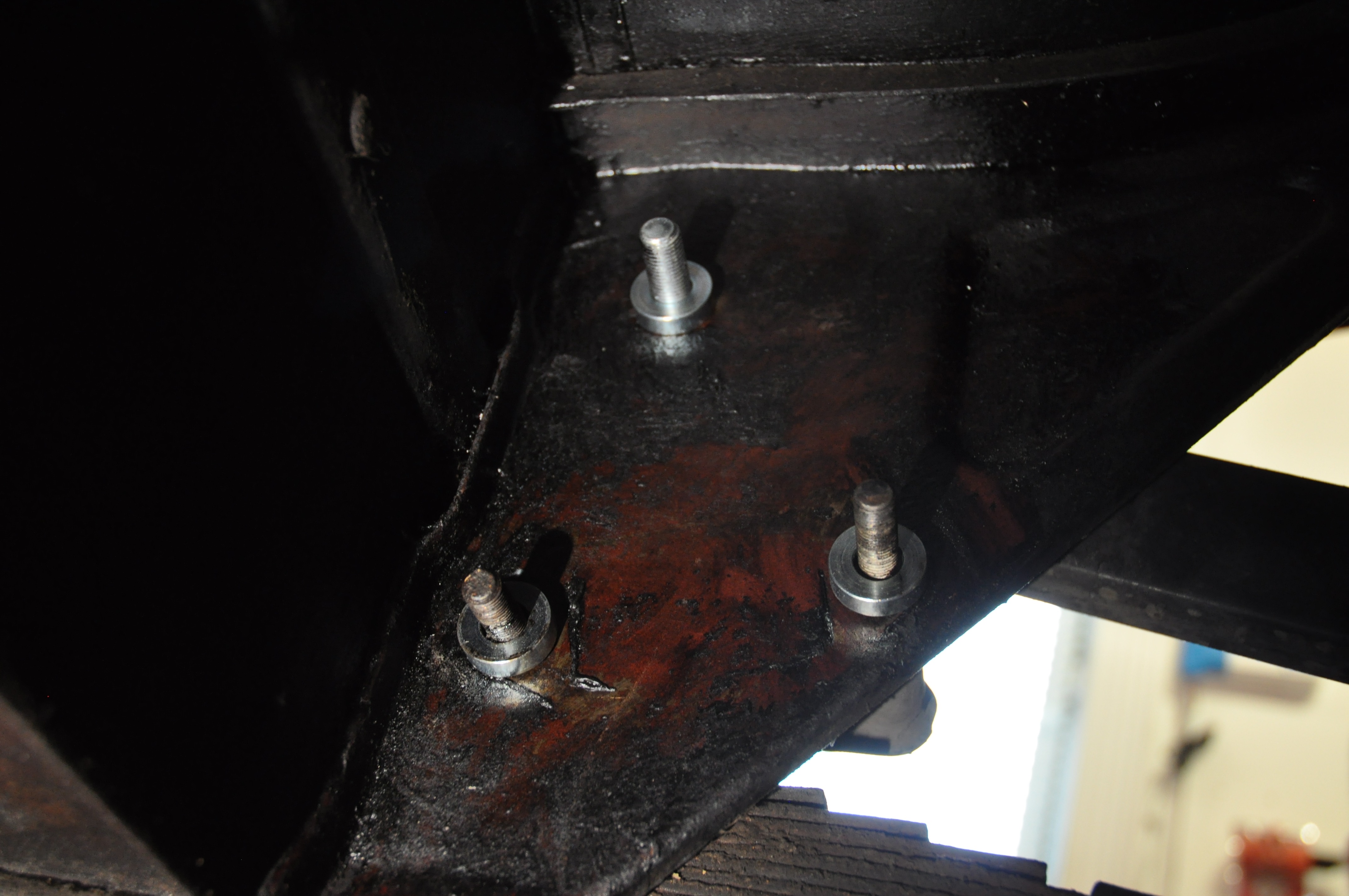
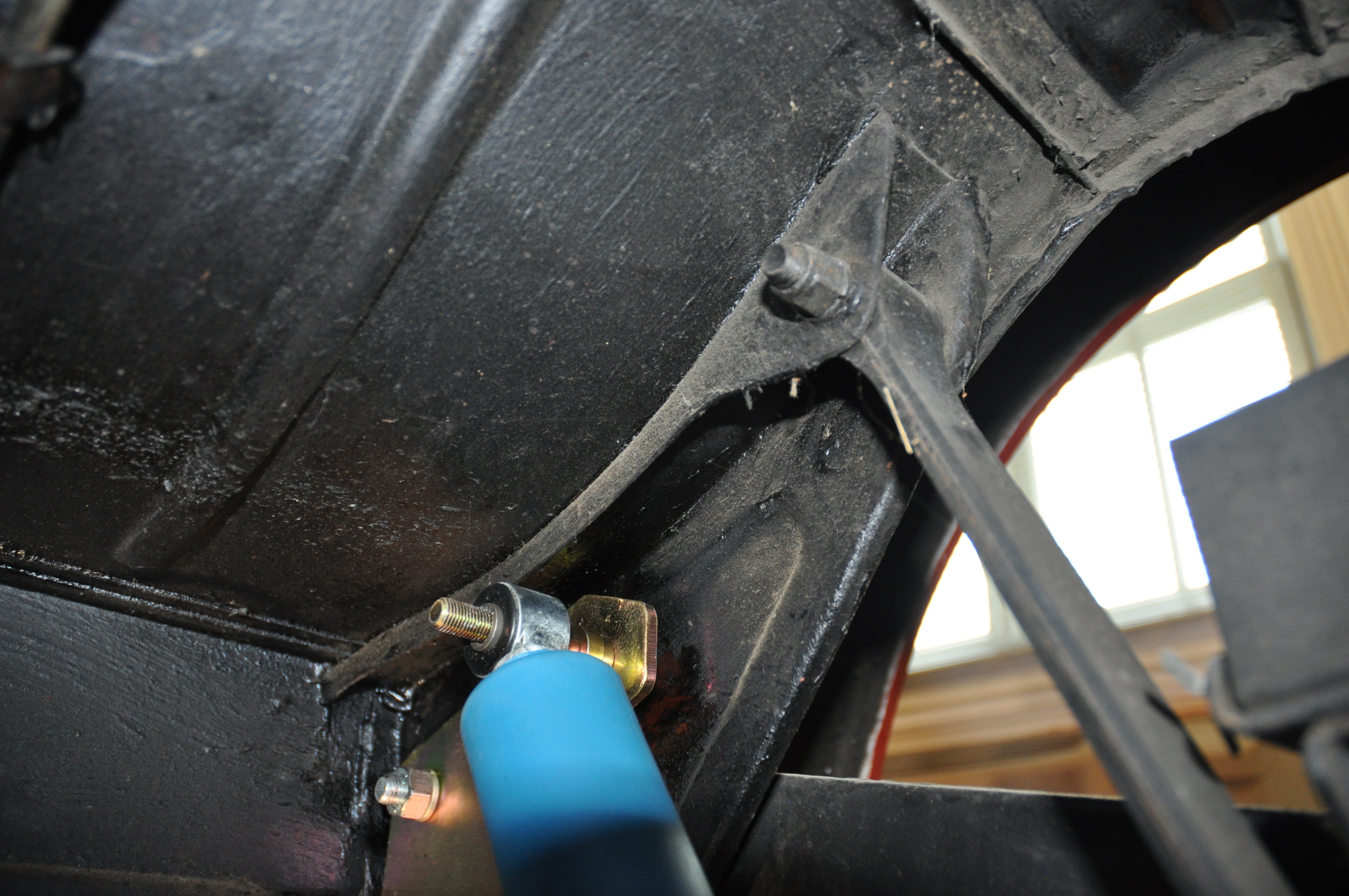
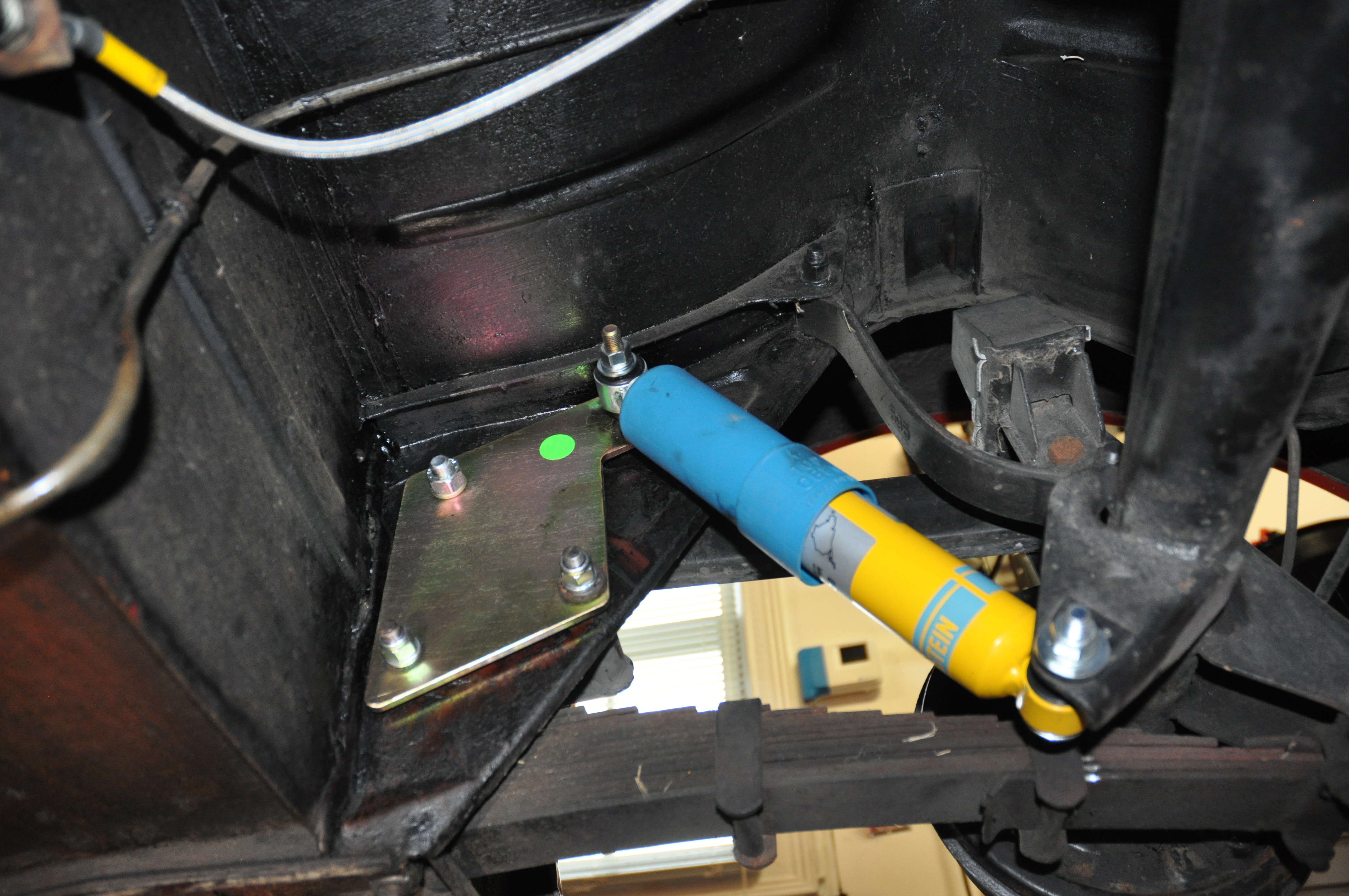
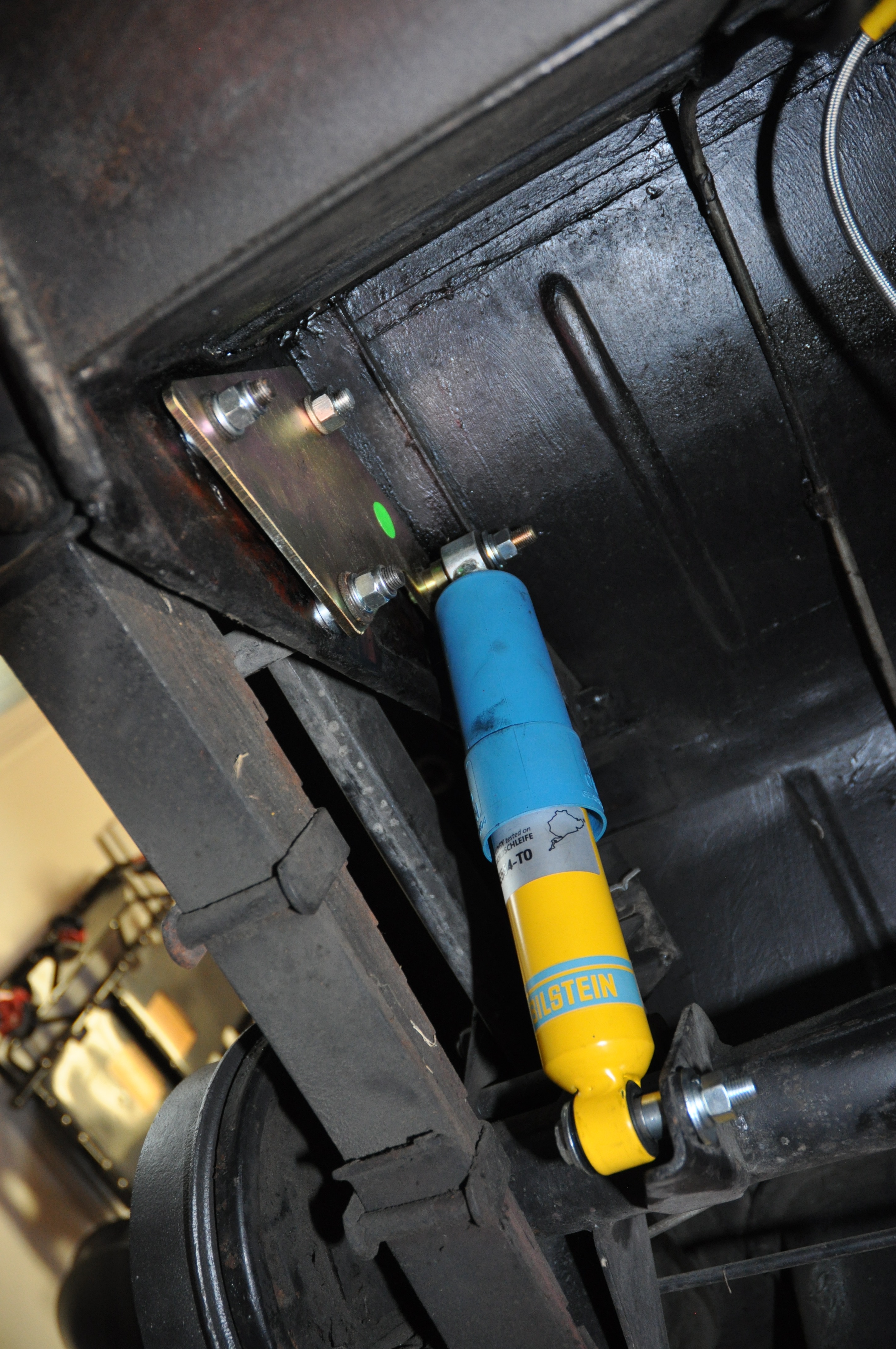
Tube Shocks
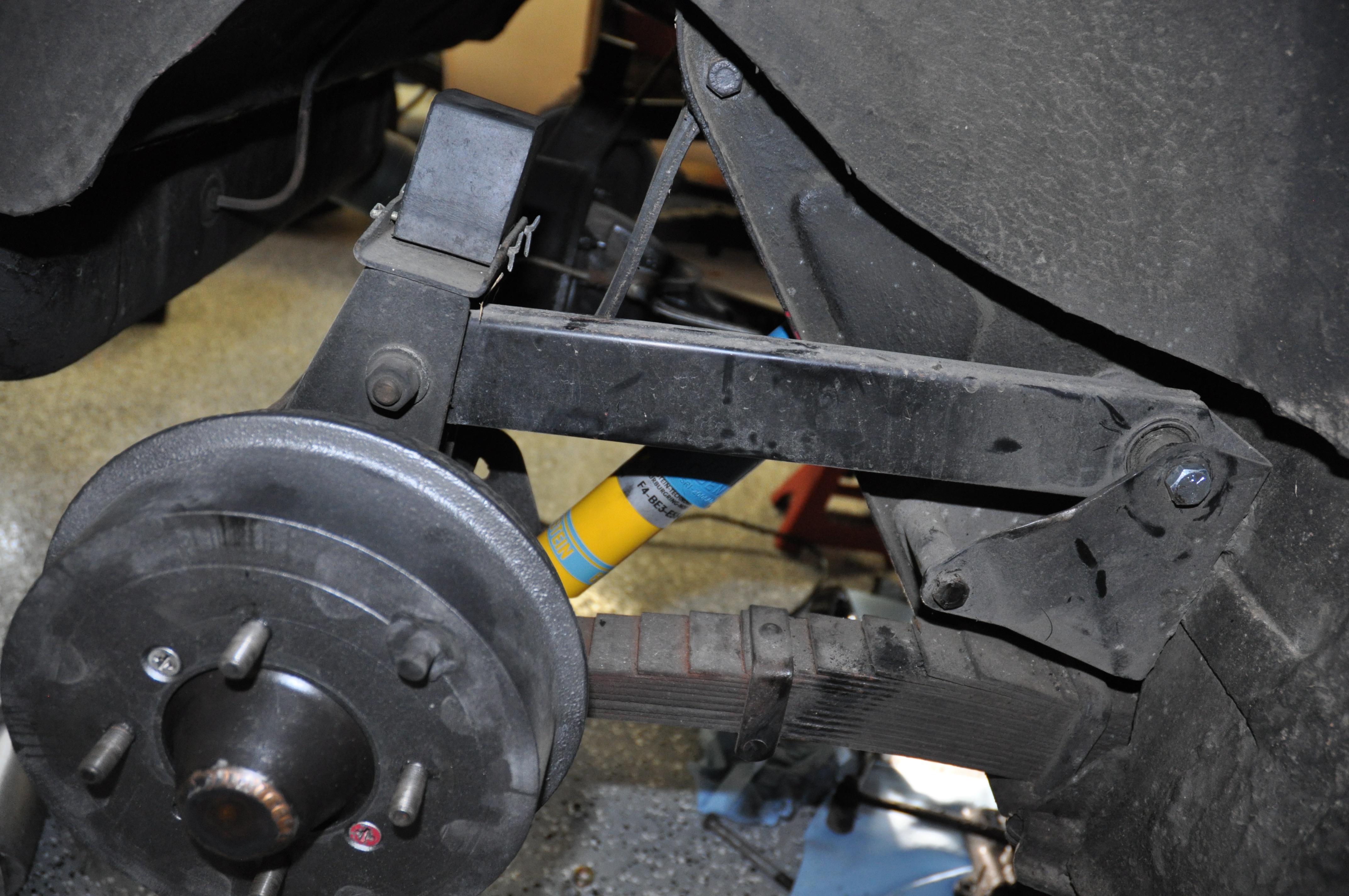
As with the front shocks, I decided to install Bilstein Tube shocks supplied in Udo Putzke’s Fahrspass http://www.putzkes-fahrspass.com/Eng/kits.html Tube Shock Kit in the rear. I ave been very pleased with the performance of the shocks. This is a document describing the installation: Putzkes Fahrspass Tube Shock Kit.

Bilstein Tube Shock
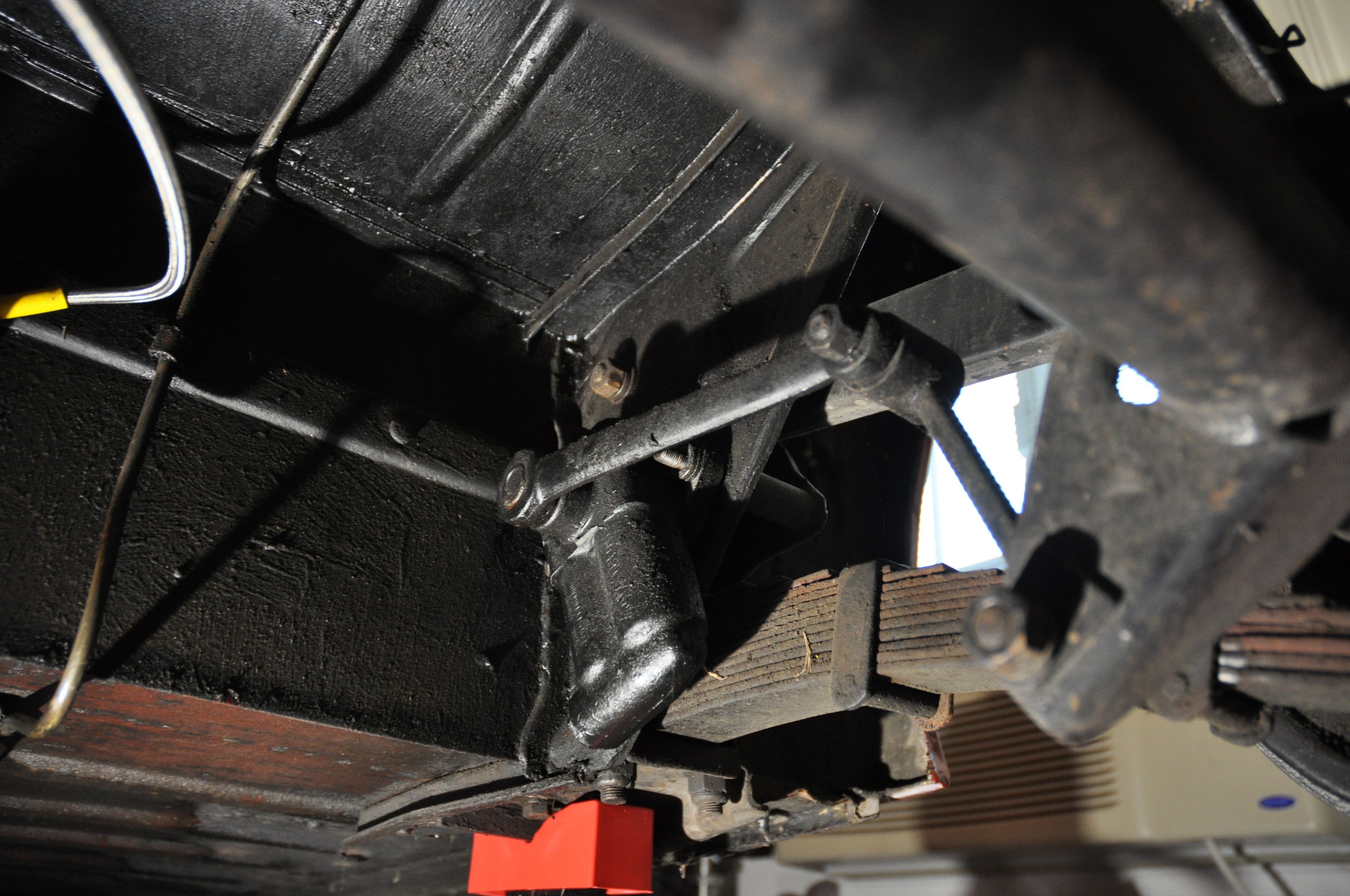
Rear Leaf Springs
Having used the Jule Enterprises frame, I also decided on Martin Jansen’s custom made leaf springs. They worked perfectly. Ride is great and the car sits nicely with the proper gap between the tires and the body. Martin’s springs use BJ8 mounting hardware.

Leaf Spring
Rear Differential Gears
Many Healey owners who converted to the Toyota 5-speed gearboxes suggest that the 3.54 gears in the rear end make for a nice combination. Mike Lempert, who makes Healey steering wheels also arranged for the manufacture of the 3.54 gear sets. I was fortunate to be able to purchase a set and install them in the Bloody Beast.

Lempert 3.54 Gears
zz