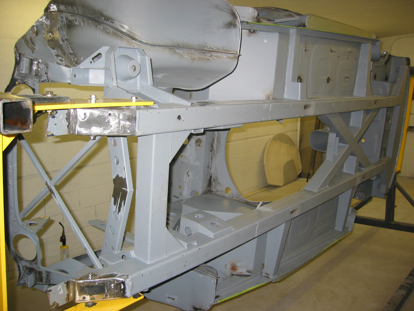
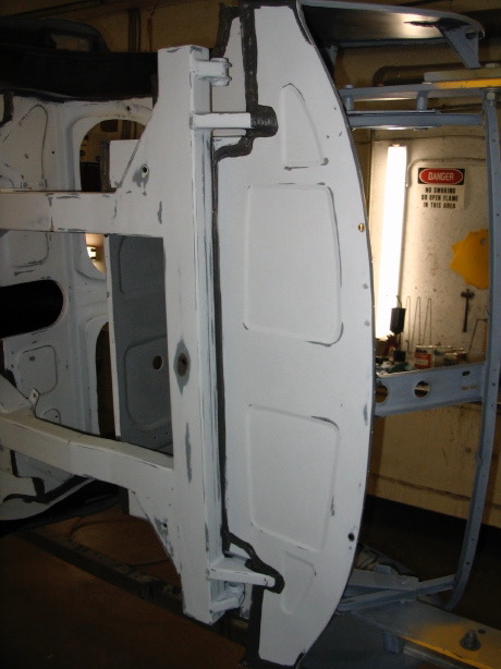
Rear Suspension Mounting
Rear Suspension
The MK2 rear suspension is a live axle leaf spring design utilizing bonded rubber bushings and pads. Torque arms with bonded rubber bushes at each end fit between brackets welded to the top of the axle and to a body cross-member at the back of the rear seat panel. Lateral location of the suspension is by means of a rubber mounted pan hard rod fit between brackets on the rear axle and the right hand chassis side member. Damping of the rear suspension is by telescopic hydraulic dampers located between brackets on the rear axle and the front of the luggage compartment floor. The dampers incorporate the bump and rebound stops which limit the movement of the rear suspension.

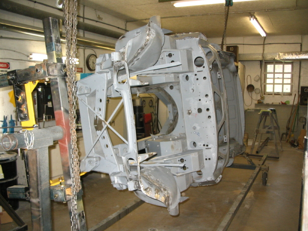
Rear Suspension Jag MK2
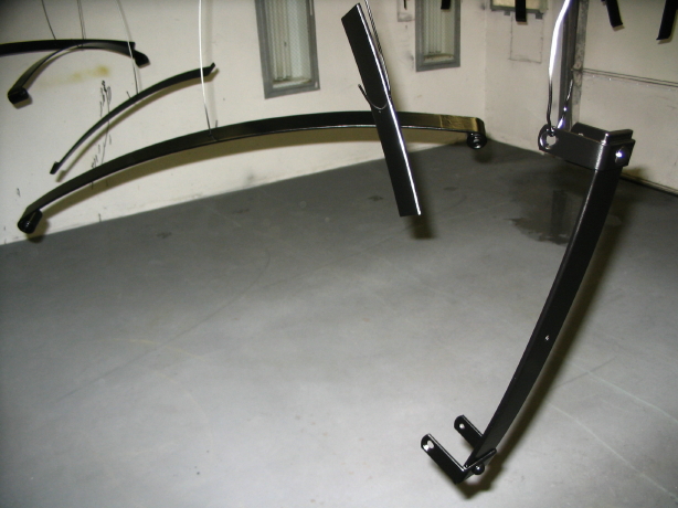
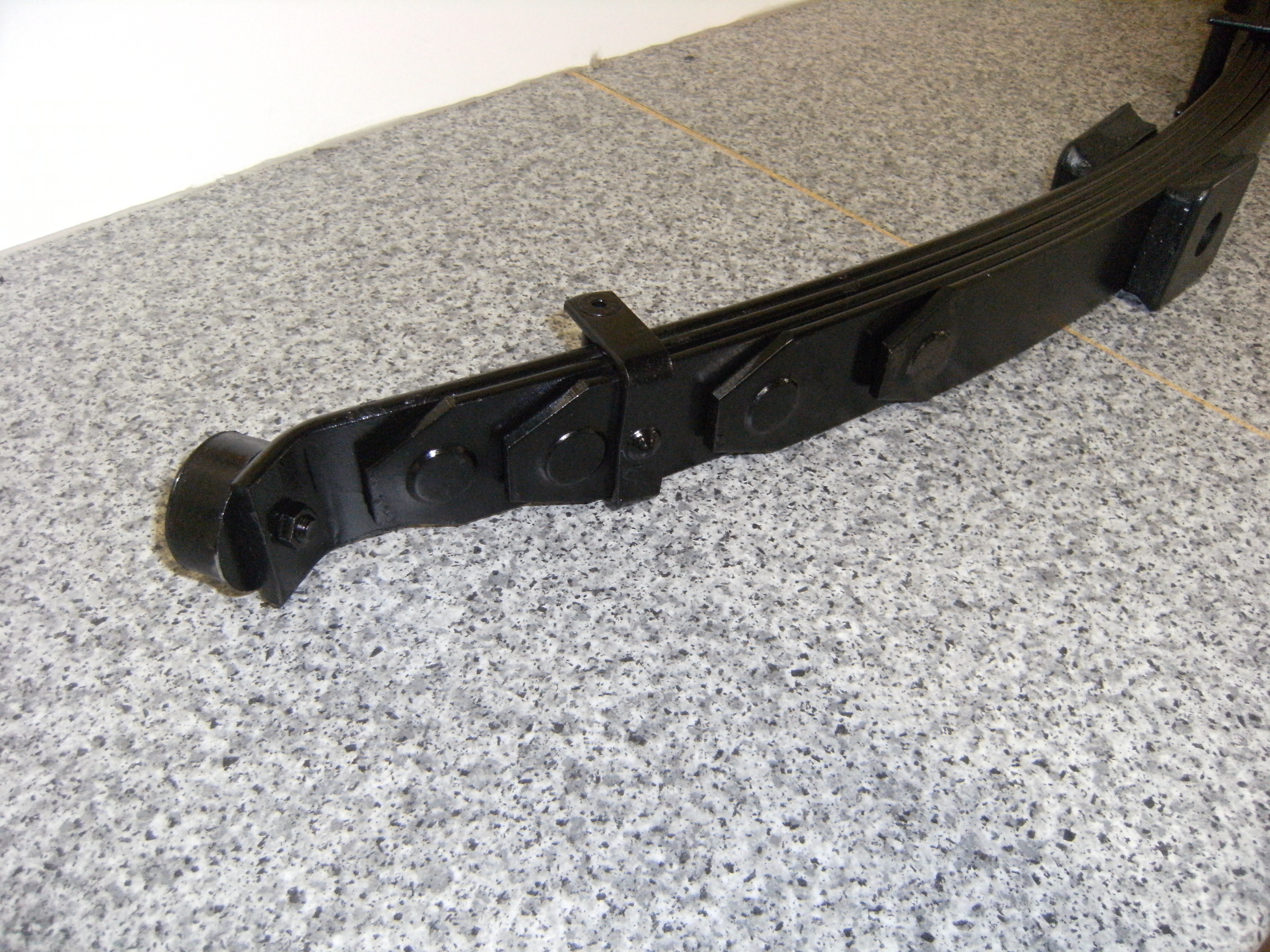
Rear Road Springs
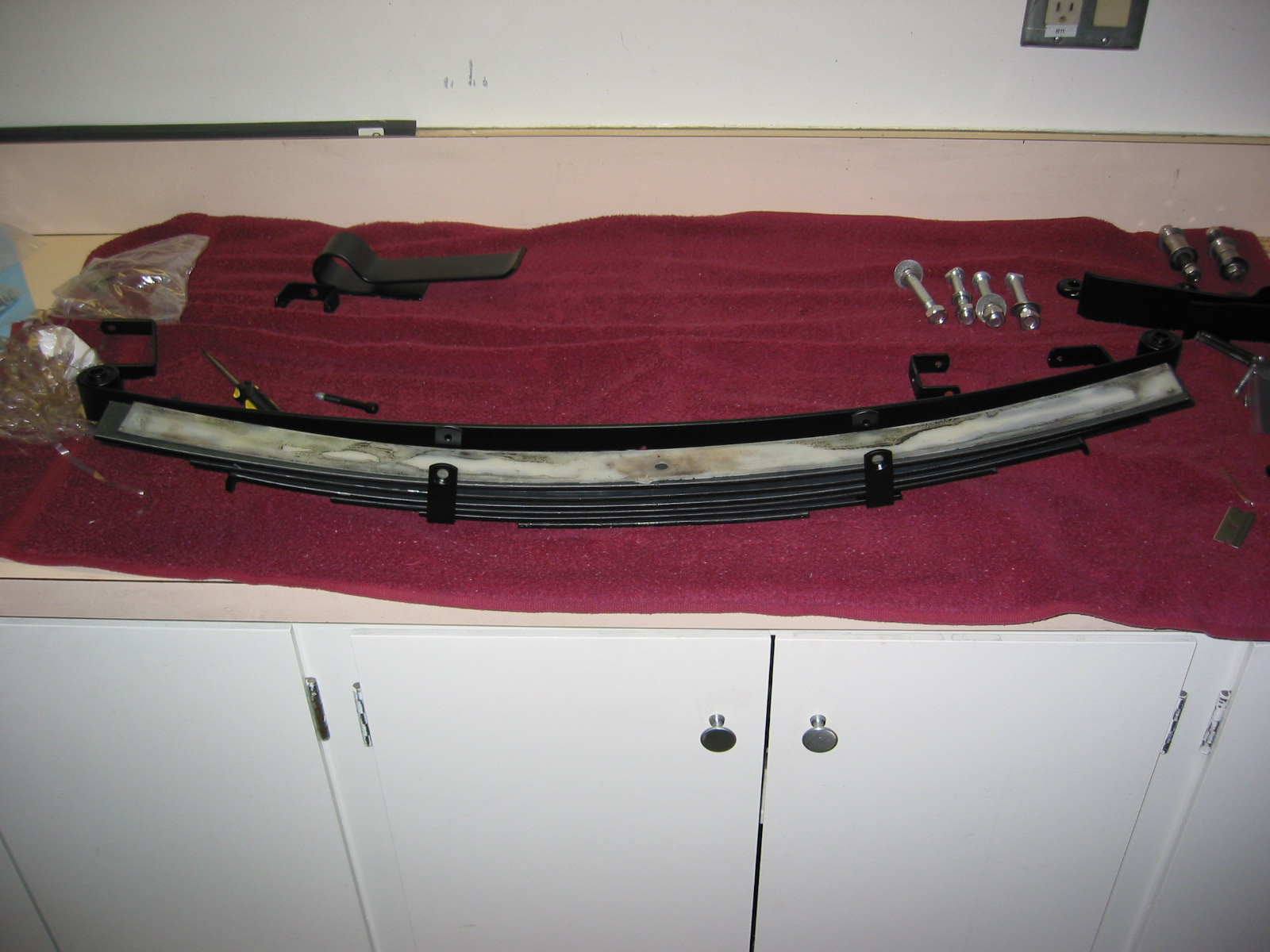
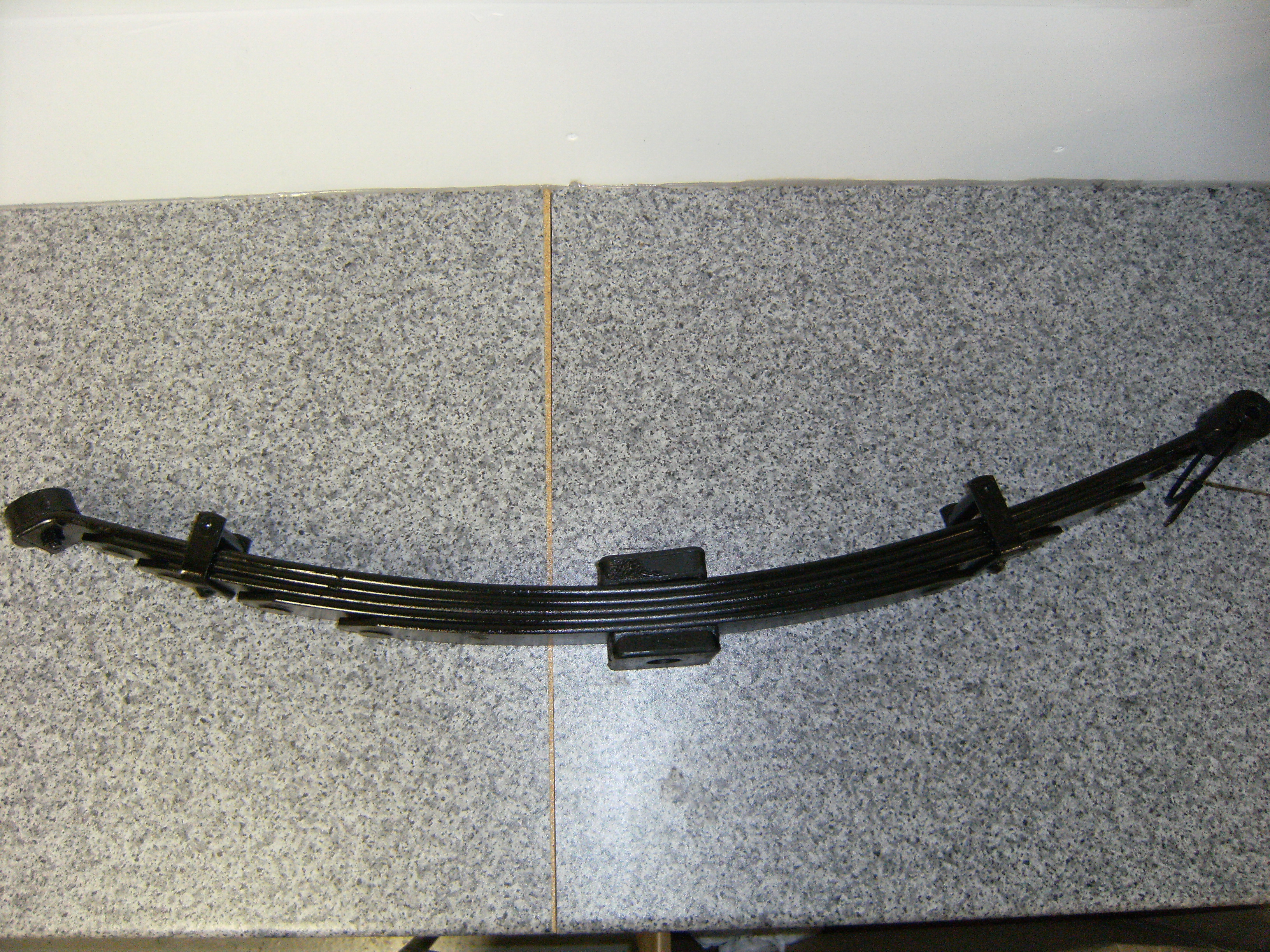
The rear road springs are rubber mounted at the front, center and rear. I was going to reuse the rear leaf springs but after disassembling them I found them to not have sufficient arc on the lower leaf. The manual calls for a camber of 3.45” to 3.78”. Mine only measured about 3.25. I could have them re-arced, but I decided to just purchase new springs from SNG Barrett.

Free Camber On Road Spring 3.45″ to 3.7″
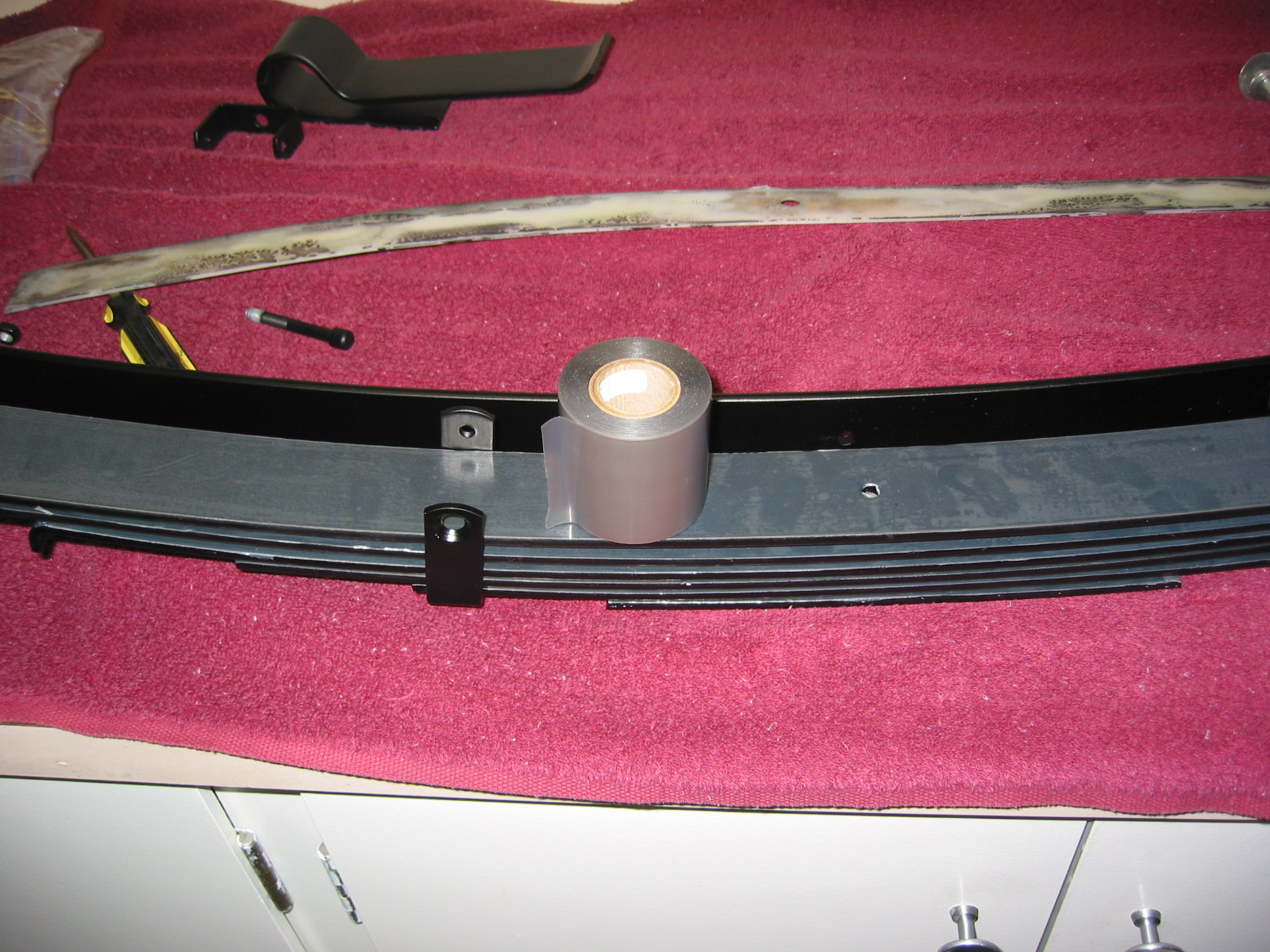
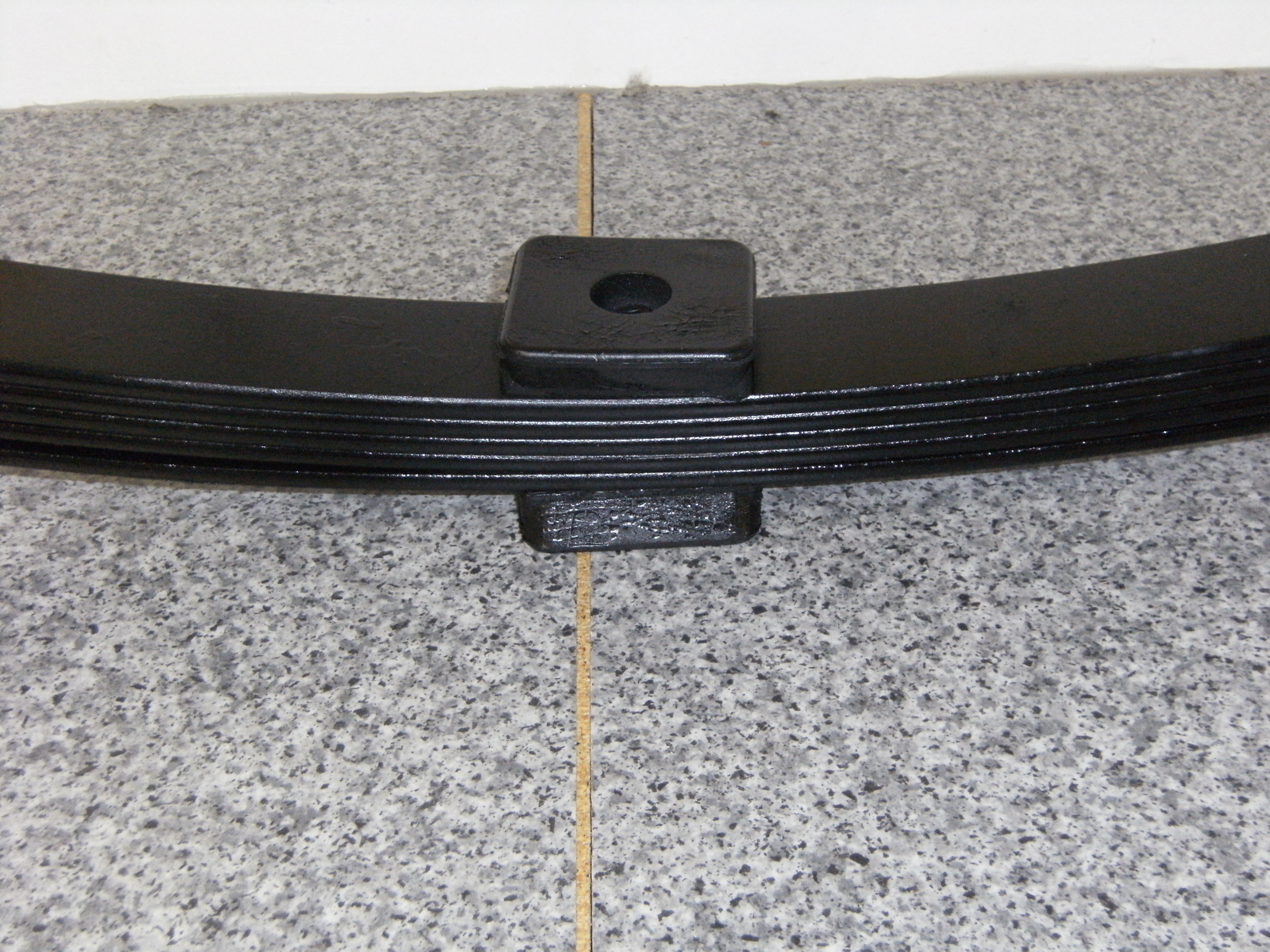
I noticed that the original springs had rubber “buttons” located between the leaves. The new replacement springs from SNG Barratt do not, and while not a condemnation, I notice that these springs are also made in India. I heard reports from a number of MK2 restorers that the rear of the car was sitting high with these springs.
All of this caused me to look a little harder for springs closer to the originals. Owen Spring in the UK makes MK2 springs that at least look much closer to the original design including the “buttons.” Owen uses British Classic Car Parts to market their classic car springs. I spoke with Jody Walker the product Development Engineer and decided to purchase a pair after he sent images to me. Quite a bit more expensive than the SNG Barratt product, but hopefully a superior spring that will yield the proper ride height. Including delivery to Virginia the springs were a little over $500.00.
British Classic Car Parts
Unit 8, The Old Saw Mills, Colaton Raleigh, Devon, EX10 0HP, UK.
+44(0) 1395 568777 | Mobile +44 (0) 7969 013702 |
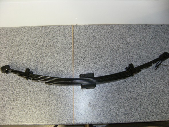
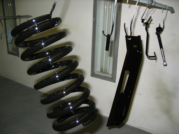
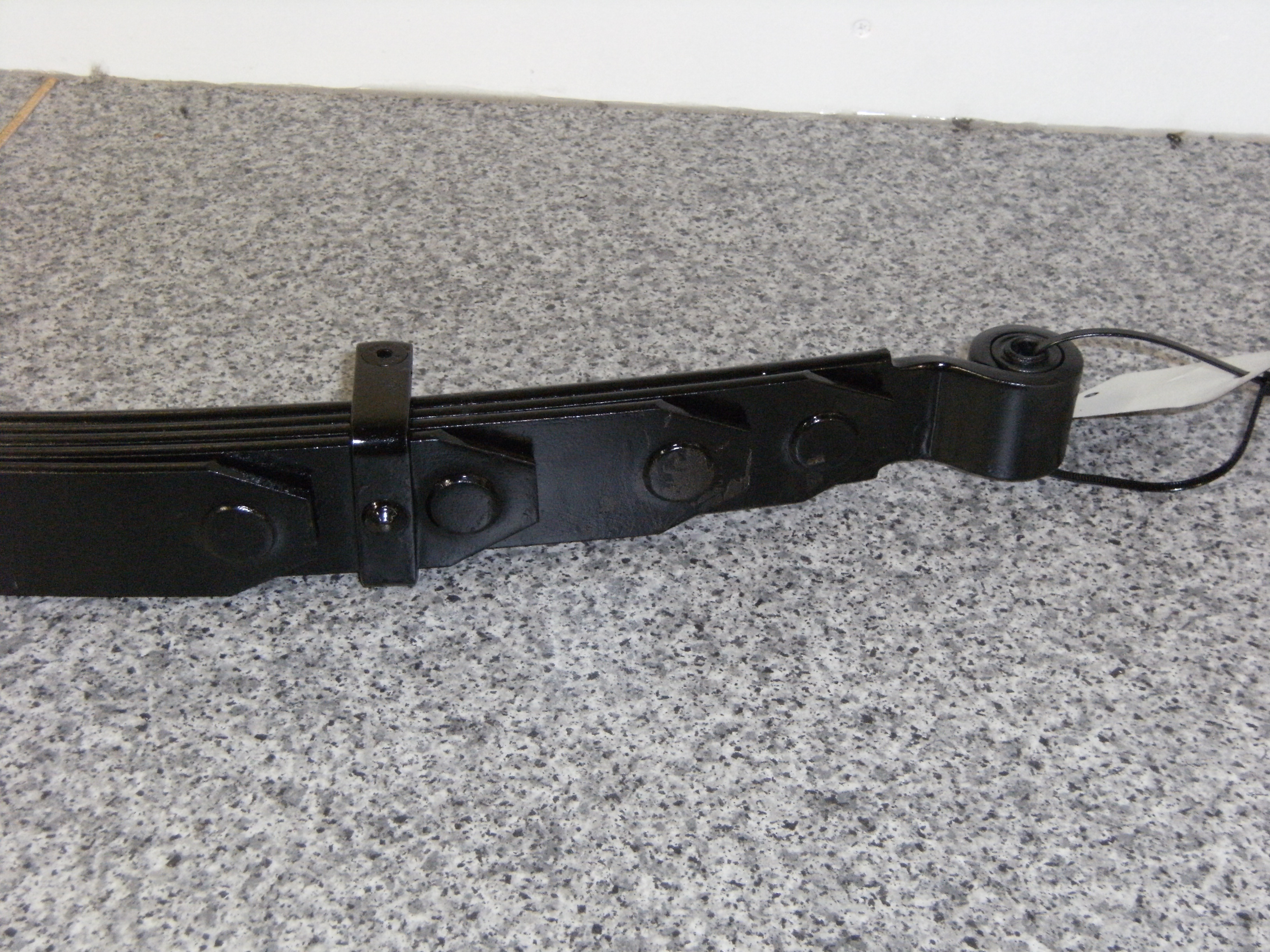
Owen Spring MK2 Rear Leaf Springs

Owen Spring MK2 Rear Leaf Springs
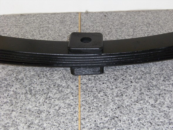
Owen Spring MK2 Rear Leaf Springs
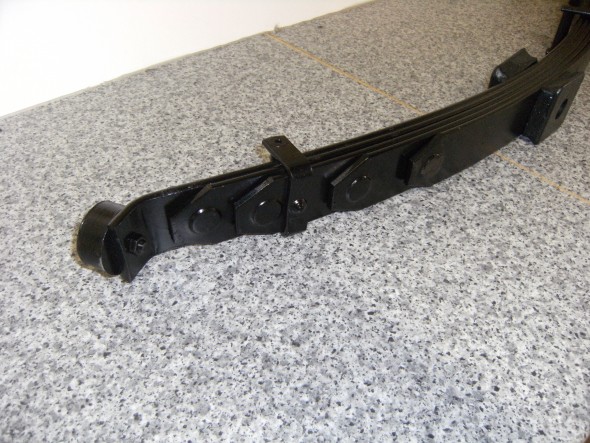
Owen Spring MK2 Rear Leaf Springs
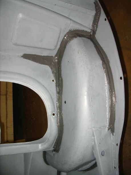
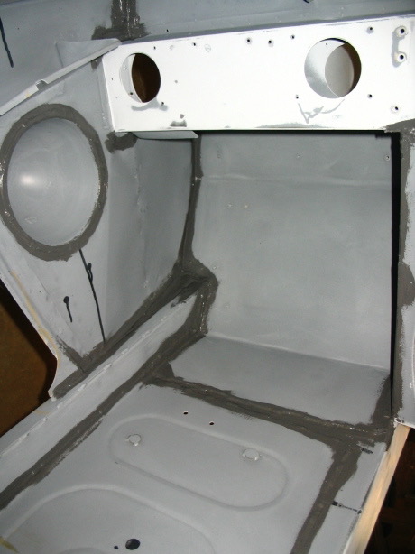
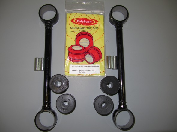
Polybush Mounting Pads and Bushings for Rear Road Springs
Polybush pads and spring eye bushes were substituted for the original rubber. The rear eye bushes were also substituted.
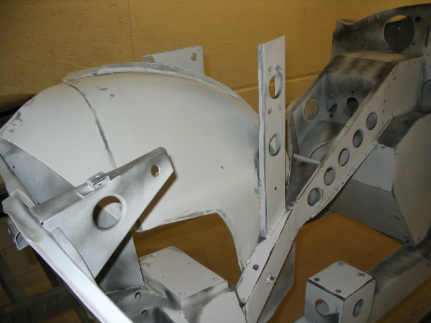
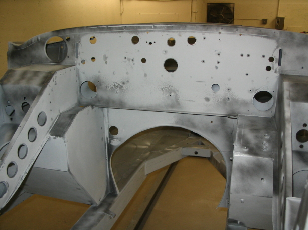
Spring Mounting Plates
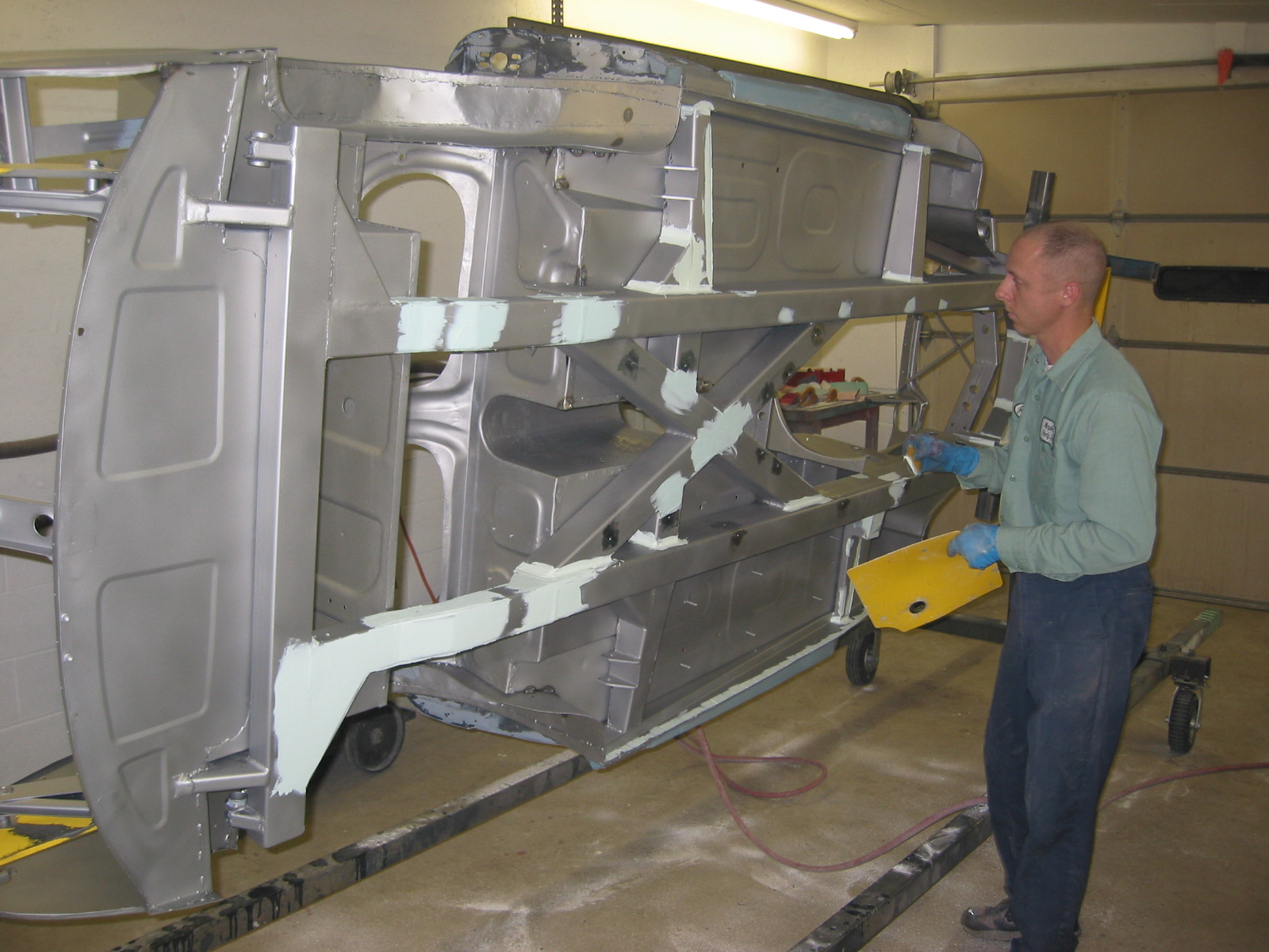
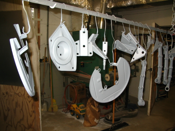
I did blast the Clamping Plate, Securing Road Spring at Center and the Mounting Plate Assembly at Front End of Road Springs with aluminum oxide and after cleaning well painted these components with gloss black POR 15 and was very satisfied with the results:

Front & Center Leaf Spring Mounting Plates

Front & Center Leaf Spring Mounting Plates
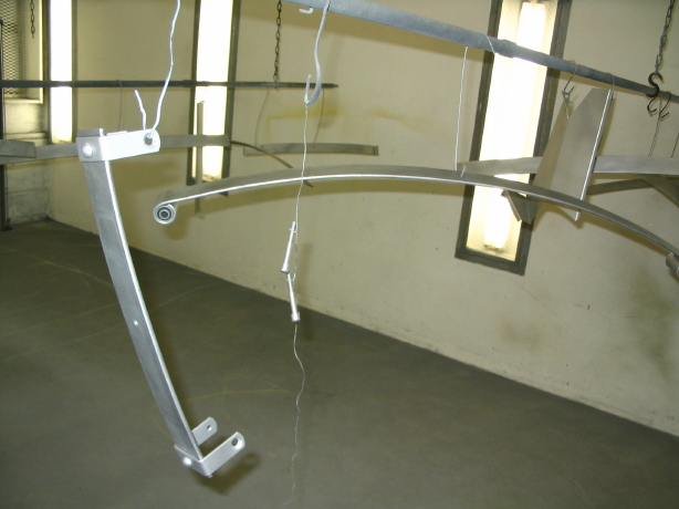
Trial Fitting the Front Leaf Spring Mounting Plate
Rear Torque Arm Assembly
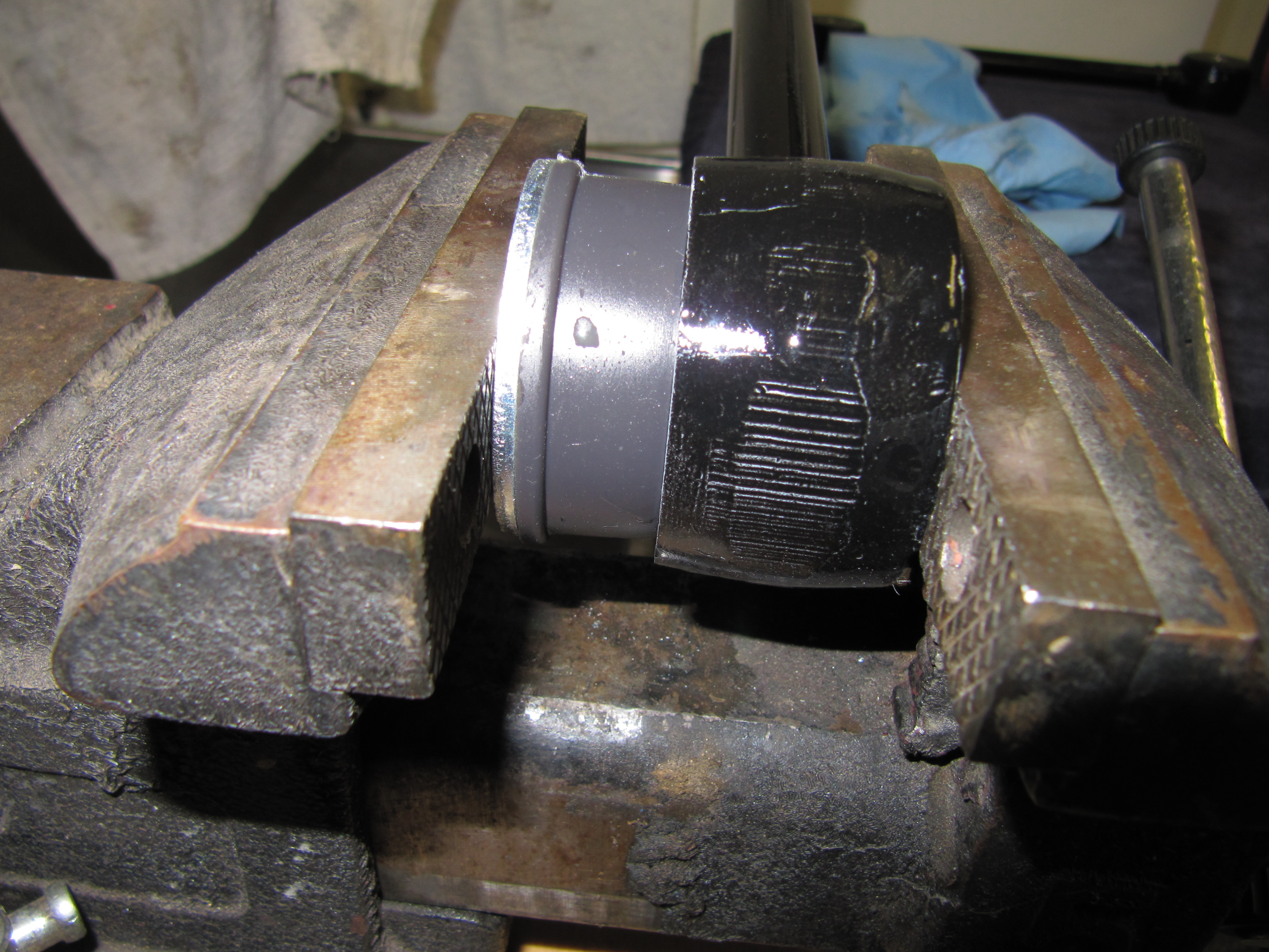
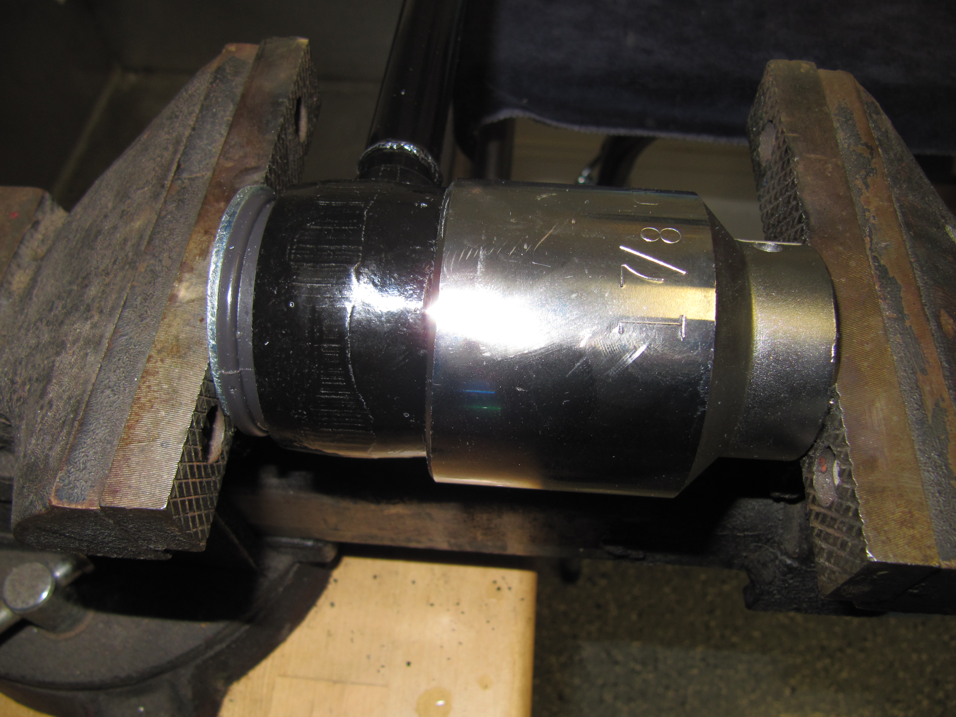
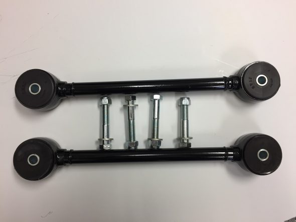
The torque arms were blasted and painted. New polybush bushings with inserts were installed. As the photos show it is useful to have a large socket (1 7/8″) and a fender washer handy to help press in the bushings with the aid of a little soapy water. Four hex head 7/16″ – 20 x 2 1/2″ bolts with 7/16″ flat washers and 7/16″ – 20 nylock nuts secure the torque rod ends to the body and the axle.
Torque Arms & Bushes

Getting it Started
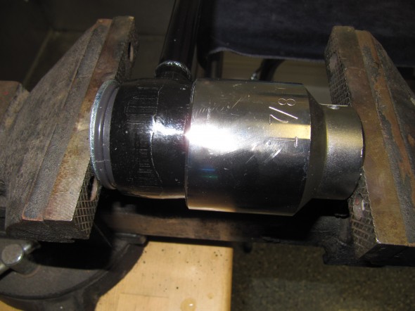
Squeezing the bushing

Torque Arms and Polybushings Installed
Panhard Rod
I could have cleaned up the washers and the Panhard Rod, but decided to simply replace the assembly with new components. The assembly is held together by a 1/2″ – 20 nylock nut at each end of the rod. I replaced the rubber bushes with Polybush bushes.

Panhard Rod New and Old

Panhard Rod Assembly
Rear Shock Absorbers
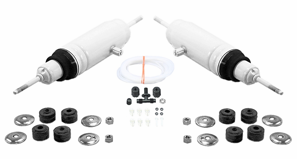
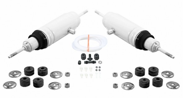
Mike Eck mikeeck@optonline.net a frequent contributor to the MK2 Forums and email list recommended using Monroe air shocks in the rear of the car. With their adjustability the ride height of the car can be modified. Curiously, they are also recommended for and fit some Edsel models! I decided to give them a try. They were available from my local NAPA store. They may be inflated up to 150 psi. They are sold as a pair including air line, air fittings, and air fill kit. Although the image below shows the shocks as white they are actually black.
Mike states:
“They each have a compression fitting and they come with a length of hose, a “T” junction and a single Schrader valve, but there’s nothing to keep you from plumbing your own separate system. They have about 2.75″ of adjustment range. When I give them about 20 psi the rear of the car seems to disappear. I steer the front and the rear simply follows along. Give ’em a try!”
Specifications:
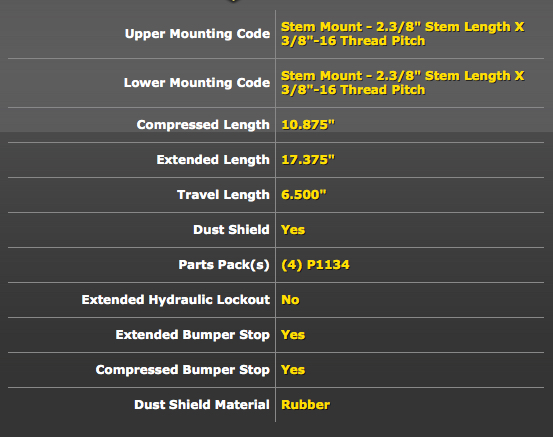
Monroe MA705 Rear Shocks
Monroe MA705 Rear Shocks
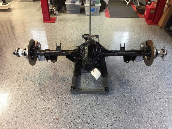
Installation of the Rear Suspension and Axle
I had heard from a number of folks who have actually installed the MK2 rear suspension that hanging the axle in the car with the torsion arms and leaf springs can be a real challenge. I don’t know if I had beginner’s luck or if I just had the sequencing of the process nailed perfectly, but whatever the reason, I installed the assembly by myself without any real difficulties. I should note that one piece of equipment made the job much easier than it might have otherwise been: a motorcycle/ATV lift. I purchased mine from Harbor Freight for $69.00, but they are available from Sears, Home Depot or other similar stores for less than $100. This device makes the axle much more stable and balanced than it would be on the single pedestal of a floor jack.
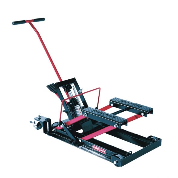
Motorcycle ATV lift
At the time of installation, I had the brake rotors, calipers, new hubs with new bearings and the hydraulic pipes mounted on the axle. I chose to wait to secure the handbrake assembly to the axle until after the axle was in the car. More information about the axle assembly can be found in the “Rear Axle Post” of this website https://valvechatter.com/?p=4072
This is the sequence of my installation:
As a service manual indicates final tightening of the bolts securing various components to the chassis must be carried out with the car in its normal riding position, that is, with full weight on the suspension. So in the sequence of steps below, all bolts/nuts are left loose and will not be tightened until he cat is under load.
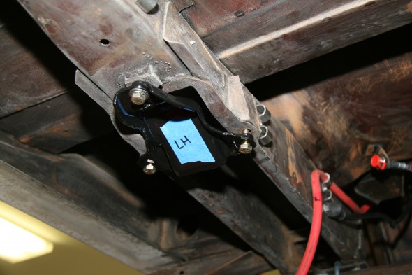
First, I installed both torsion arms to the vehicle mounts.
Torsion arms with mounting bolts and nylock nuts
LH Torsion Arm Mounted to Chassis
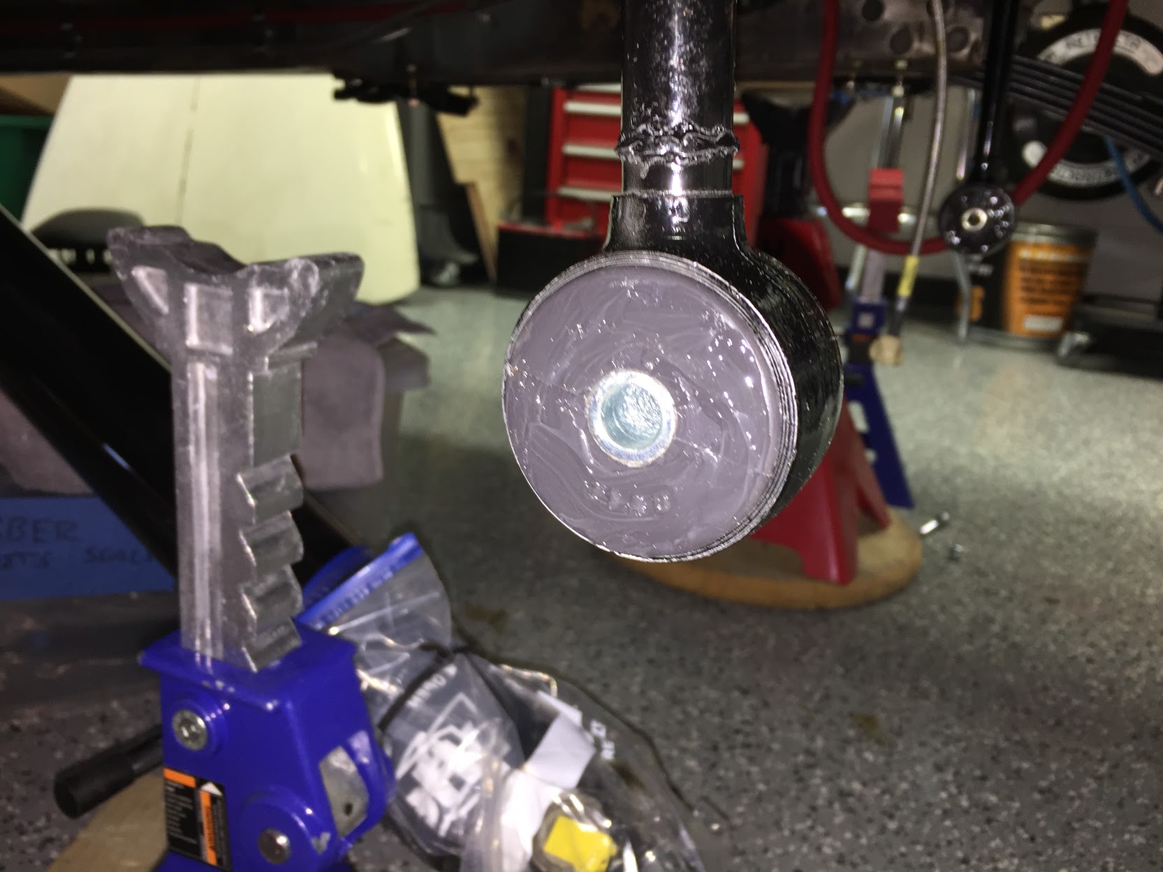
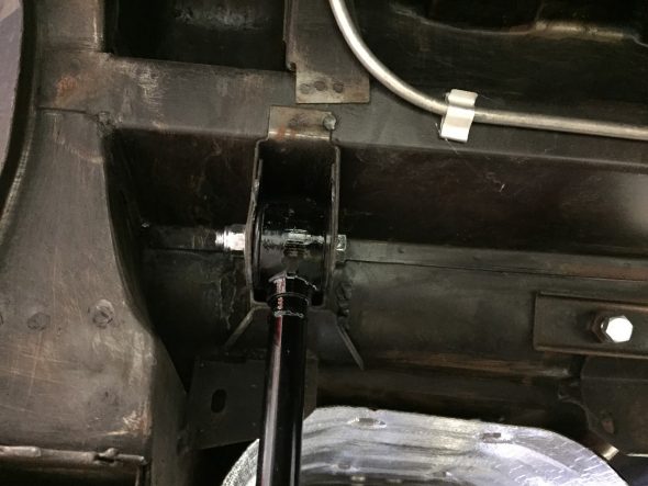
As mentioned above I used polybush bushings and I liberally coated the outer surfaces of the bushes with Prothane Super Grease. I used this grease on my Healey when I restored it in 2008 and have never experienced any squeaking. I happened to purchase the grease from Summit Racing but it is available from other similar vendors as well.
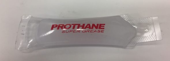
Prothane Super Grease

Prothane grease on torsion arm poly bushing
Second, I installed the LH and RH Front Spring Mounting Plates. I started each of the three mounting bolts for each bracket and all were left very loose.
Third, I placed the axle on the motorcycle lift and slid it under the car and into position to jack up to each of the torsion arms. This worked quite easily. I then slid the mounting bolts through the chassis mount and the torsion arm and loosely secured the nut to the end of the bolt for each side of the car.
Axle on Motorcycle Lift
Axle Linked to Torsion Arm
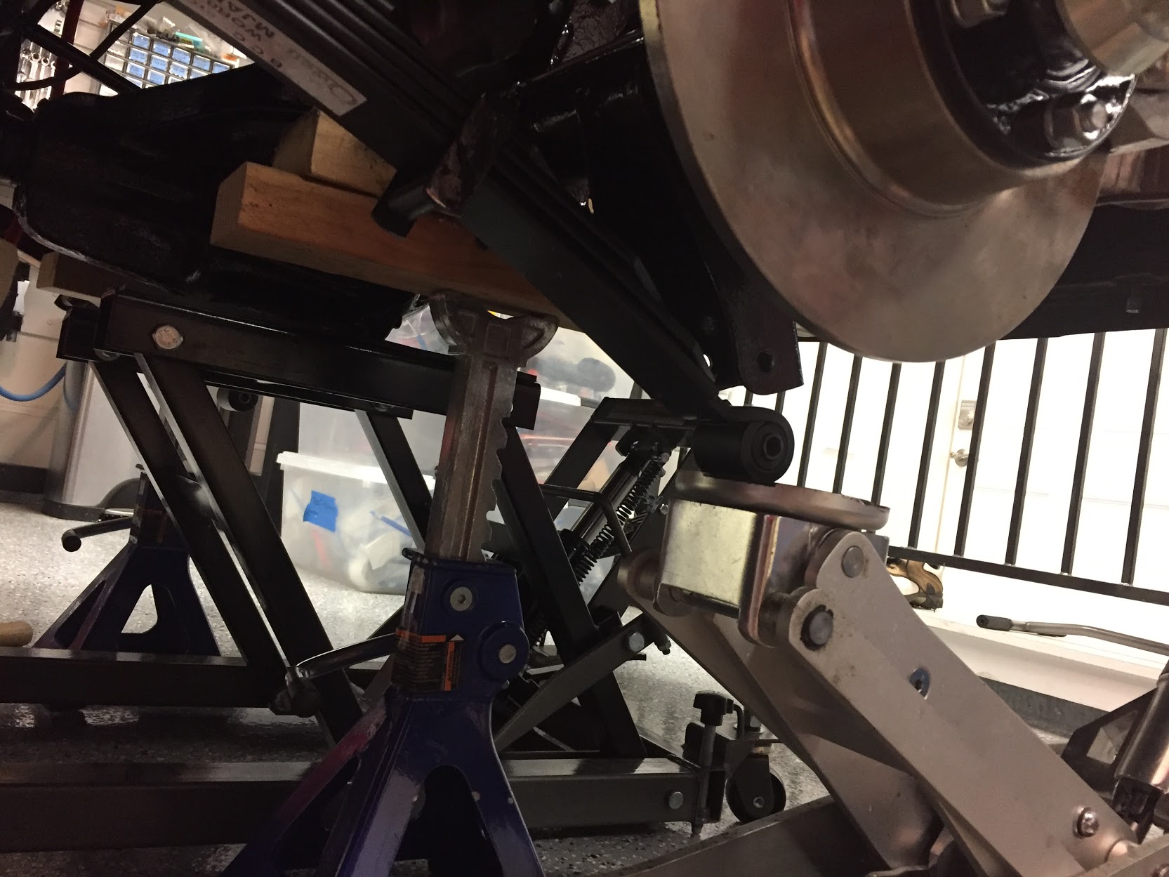
Fourth, after the axle was secured to each torsion arm with the 7/16″-20 x 2 1/2″ bolts and unlock nuts, I placed the axle on jack stands with wooden blocks in roughly the position I thought would be appropriate for the propshaft and the leaf spring eyes to keep the axle from swinging.
Axle mounted on torsion arms resting on jack stands
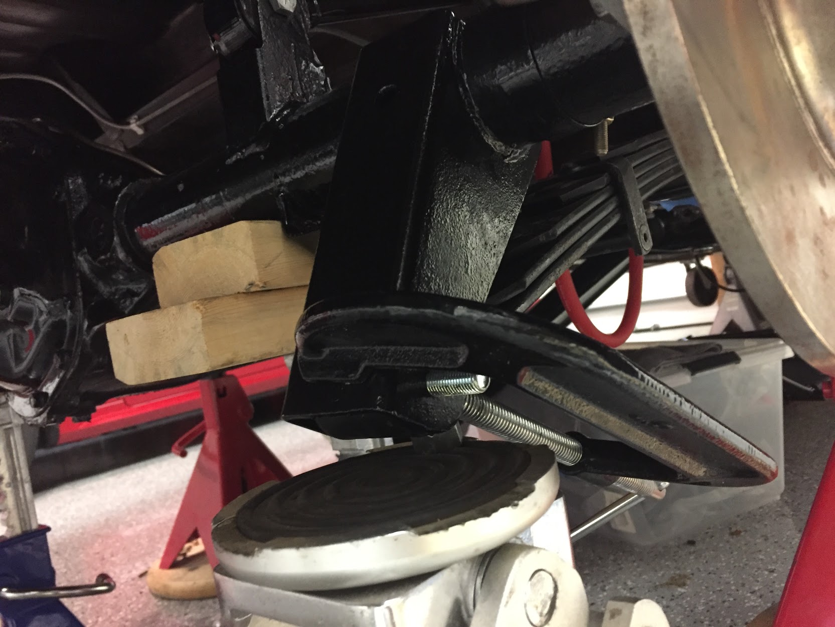
Fifth, I slid a leaf spring into its front mount and rested the eye end of the spring on my floor jack sufficiently high enough to hold the spring in place without slipping out of the front mount.

Spring Eye on Jack
With the rubber center cushions on the leaf spring I placed the center spring mount in position and loosely tightened the mounting bracket in place. This was made easier by starting with longer bolts than are specified and switching to the shorter bolts after the bracket is tightened down. Care should be taken to insure that the rubber cushions are centered in the bracket.
Spring Positioned on Center Chassis Mount
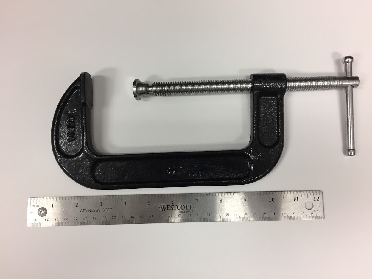
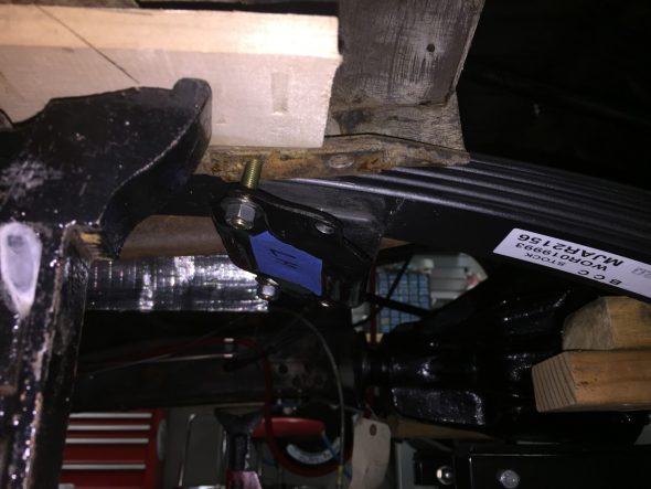
Sixth, I was then able to use the floor jack to lift the spring into the axle mount although I could not perfectly line up the eye hole in the spring end with the holes in the axle mount. I found that a fairly large “C” clamp worked like a charm to squeeze the holes into alignment allowing me to then insert the bolts and loosely tighten the nuts to secure the spring end to the axle.
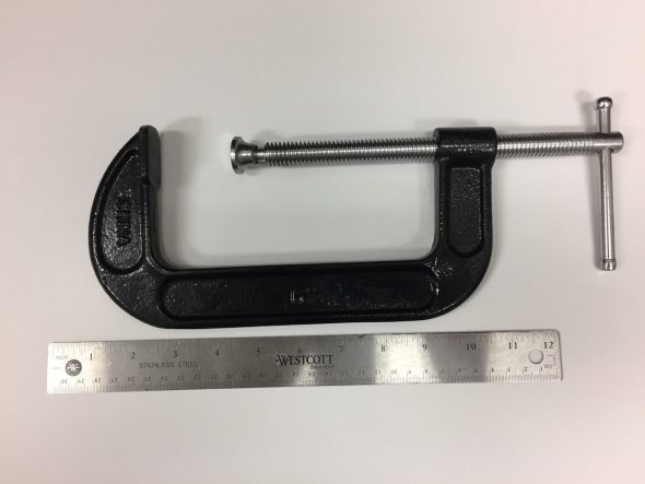
“C” Clamp
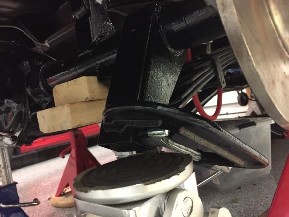
Rear Spring Bolt in Place with Clamp
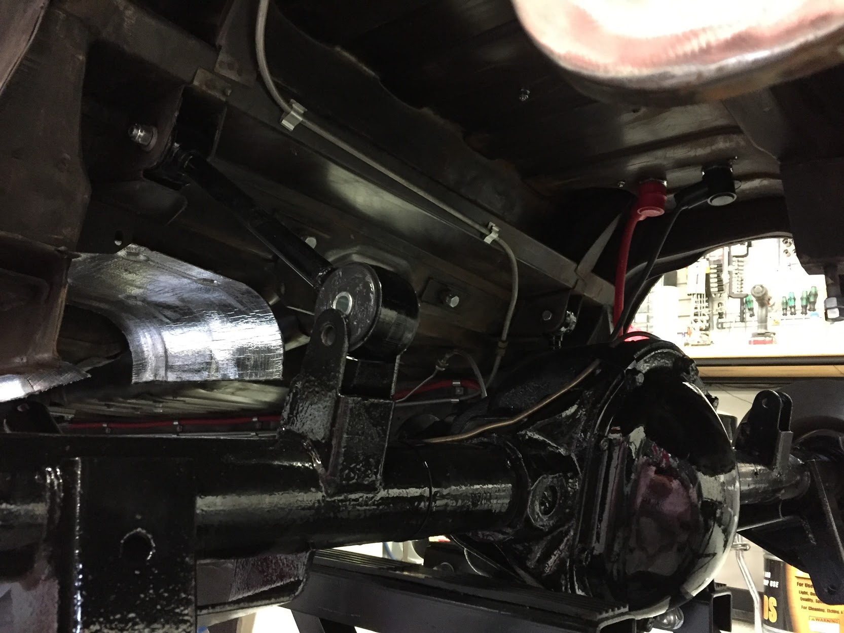
Seventh, I removed the two axle jack stands and allowed the axle to “drop” to a lower position. I then slid the floor jack under the differential pumpkin and raised the assembly slightly higher than the propshaft when it was held parallel to the garage floor. This gave me sufficient “angle” to align the propshaft rear face with the differential and I bolted them together. I used lock washers and nuts in the photo but I will substitute nylock nuts at final installation. By the way, on final assembly the leaf springs will get cleaned up and repainted as well. The spring paint as provided by the manufacturer didn’t survive the shipping from the U.K.
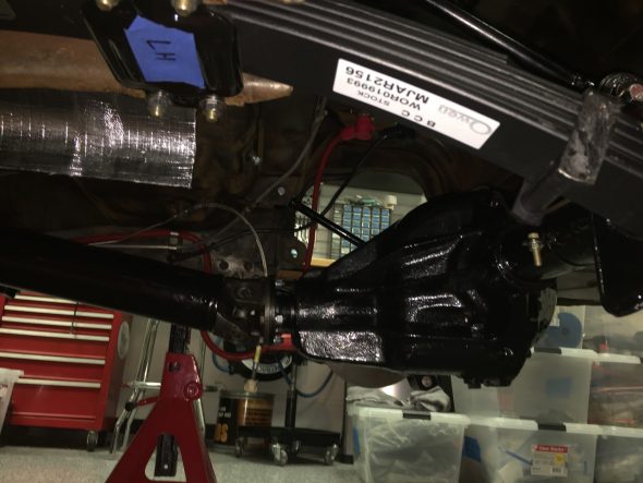
Propshaft Fastened to Rear Differential
Next come the panhard rod, the shock absorbers and the handbrake components.
The installation of the handbrake system is fully documented in the “handbrake” website entry: https://valvechatter.com/?p=3913
Rear Shock Absorbers or Dampers
As referenced earlier in this post, I am using Monroe air shocks on the rear of my MK2. This is a pdf of the Installation Instructions including diagrams: Monroe Air Shock Installation Instructions
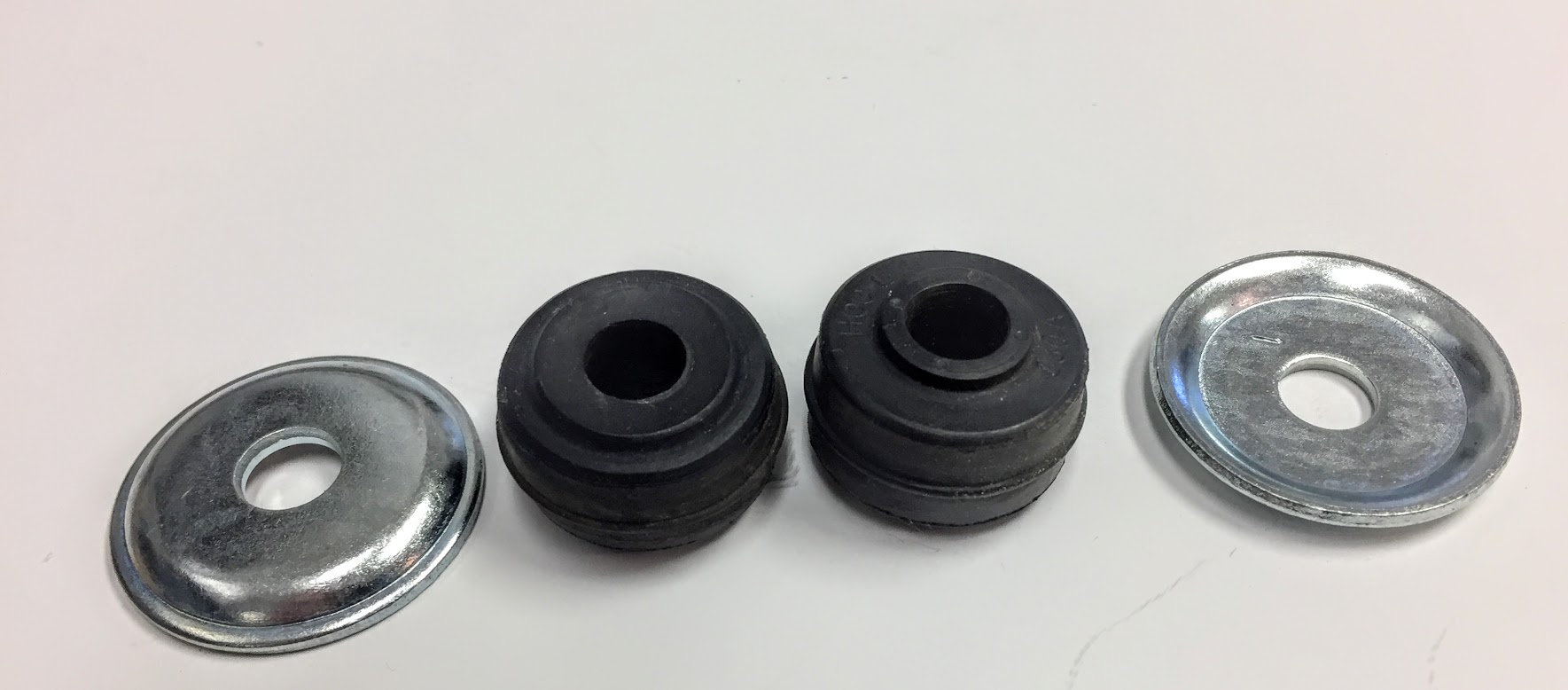
Each end of each shock uses the following rubber bushes and cupped washers for mounting the shocks to the vehicle.

Rear Shock Rubber Bushes and Cupped Washers
As one can see in the photo above, the two sides of the rubber bushes are not alike. The larger diameter “shoulder” side of the bush faces against the cupped side of the washer, while the smaller diameter “shoulder” fits against the opening in the body in the case of the upper mount and against the hole in the rear axle bracket in the case of the lower mount.
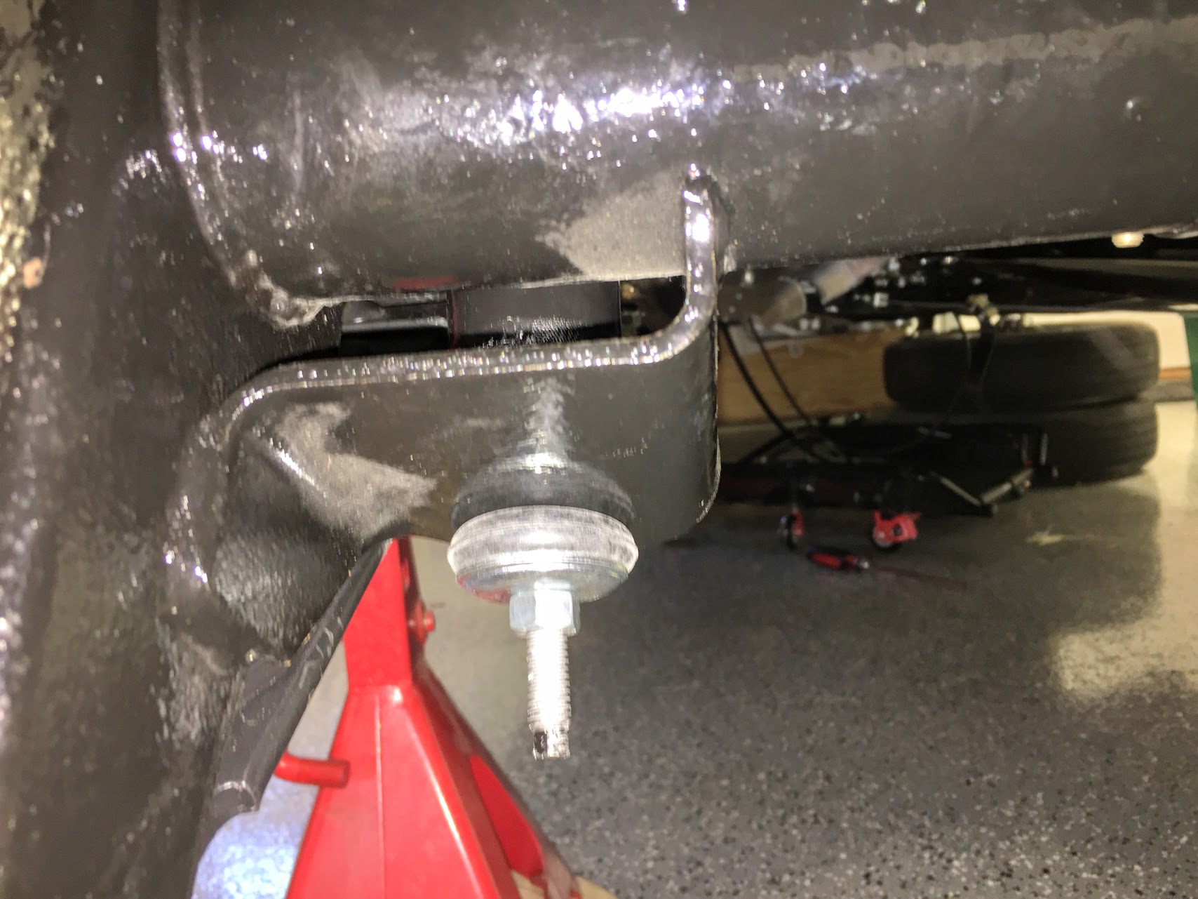
I first loosely mounted the upper ends of both of the shocks to the mounting holes in the body of the car which are located in the back rear LH and RH sides of the boot. It is useful (if not required) to have a helper to assist with this. The helper installs one cupped washer and rubber bush to the end of the shock and then pushes the shock through the floor. One must be careful to orient the air line fittings on the shock bodies so that they face inwards. This will become important later when the plumbing for the air pressure lines is installed.
Another rubber bush and cupped washer can then be placed on the threaded shock shaft inside the boot and a nylock nut can then be started on the threaded shaft. The larger diameter end of the shock faces upward.
LH Rear Shock Upper Boot Mount Loosely in Place
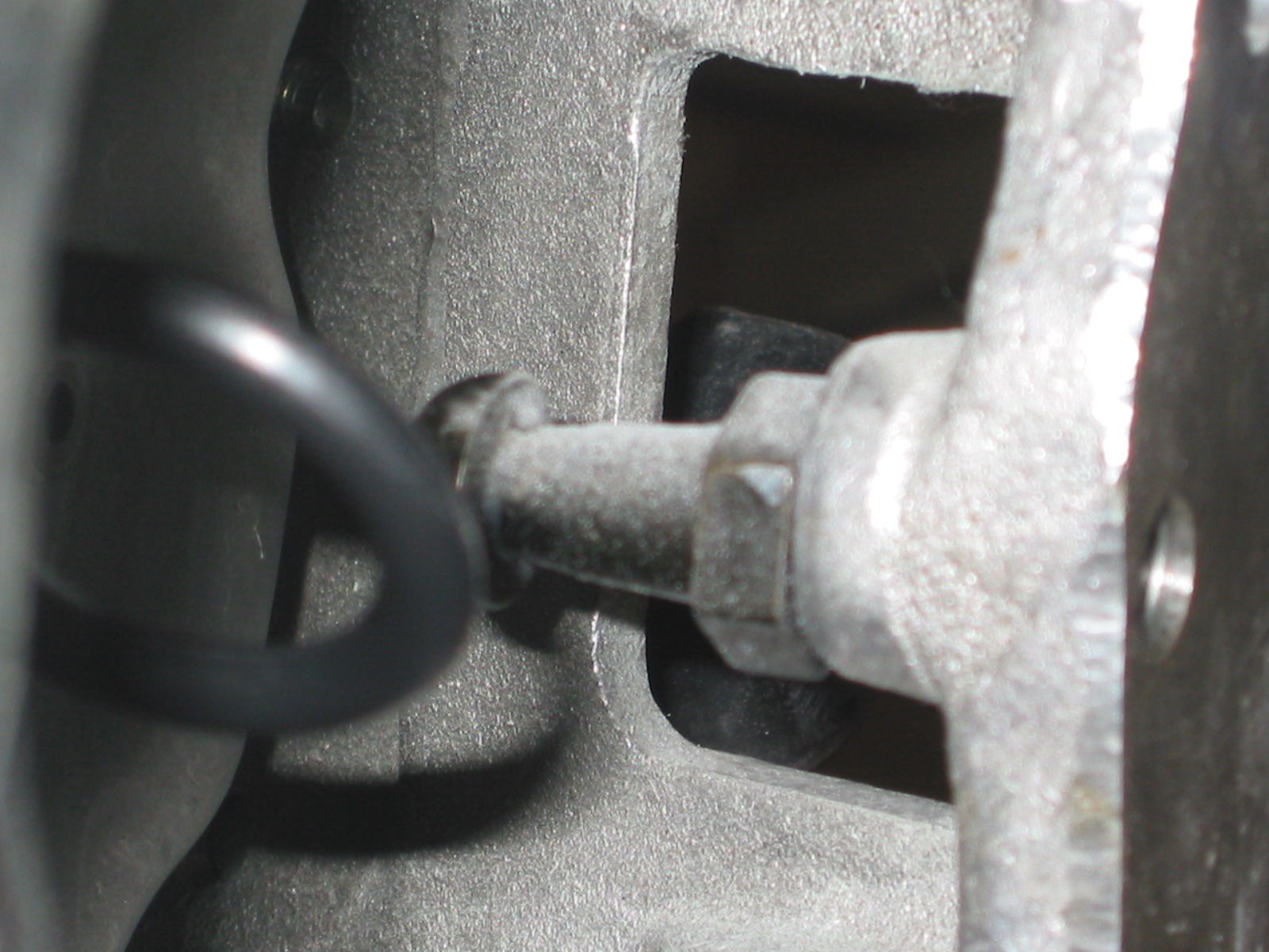
To install the lower end of the shock I found it helpful to first use my motorcycle/ATV jack (A floor jack would be fine) to raise the axle. I then placed a cupped washer and rubber bush on the end of the threaded shock shaft and pulled down on the shock to extend it through the hole in the mounting bracket on the axle. This does take a bit of arm strength!
Installing Lower End of the Shock
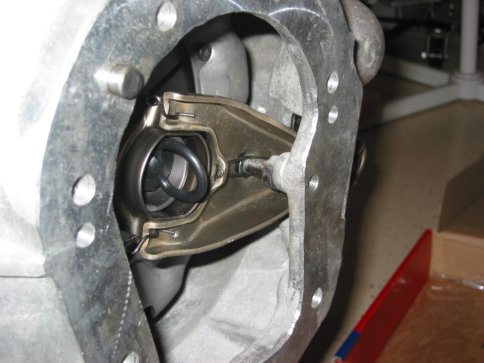
I then placed another rubber bush and cupped washer on the threaded shock shaft below the mounting bracket and again loosely mounted the shock by tightening the nylock nut.

Lower End Of Shock Loosely Mounted to Axle Bracket
I then insured that the shoulders of the rubber bushes were located inside the holes of the boot floor and the axle bracket and free to rotate in the holes. I then tightened the nylock nuts on both ends. I started with the upper ends but I don’t think it would matter. It is useful to hold the top of the shock with vice grips or a wrench so that the shock does not turn while tightening.

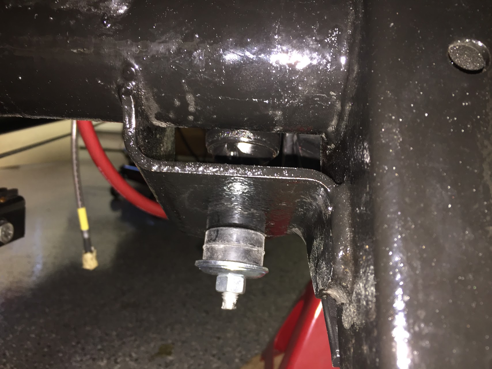
Lower End of Shock Tightened with Bushing Compressed
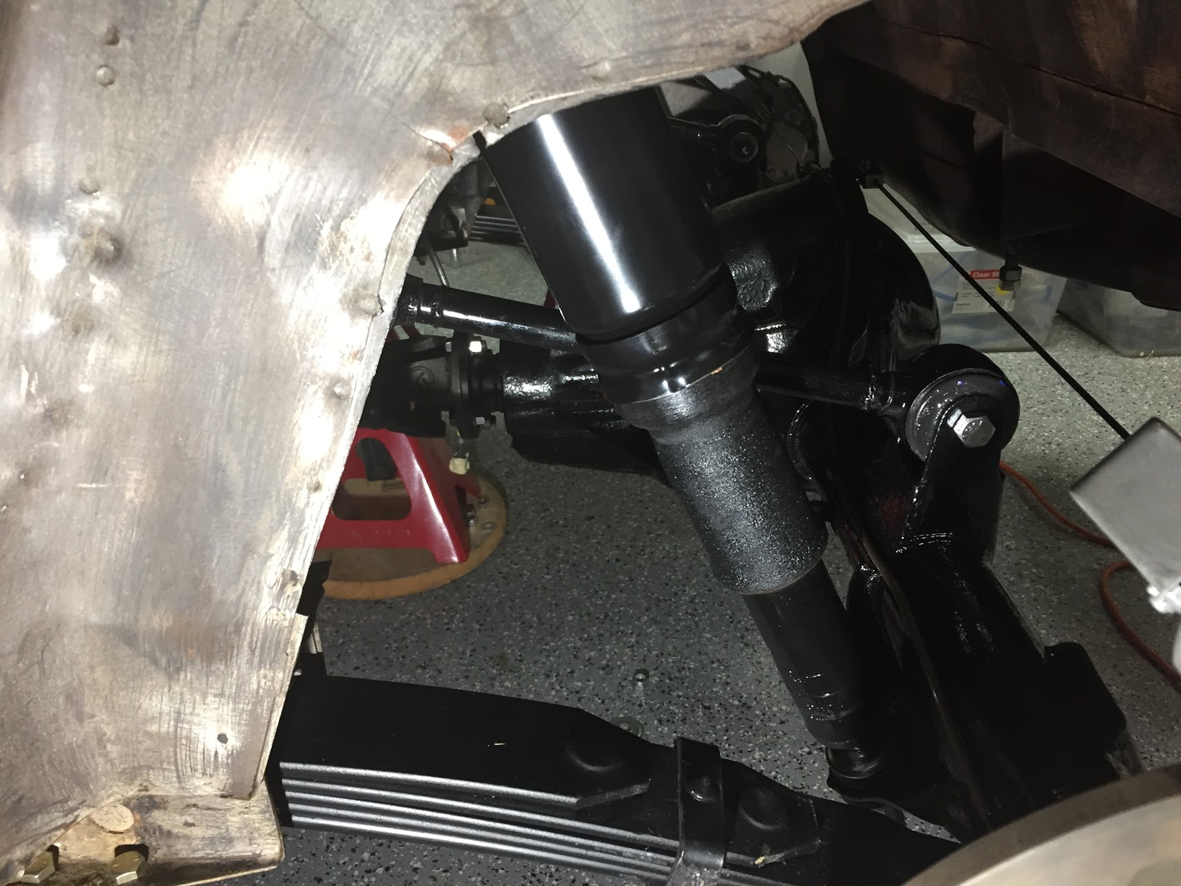
The image below shows the LH rear shock installed in it mounts. Plumbing the air is next.

LH Rear Shock Installed
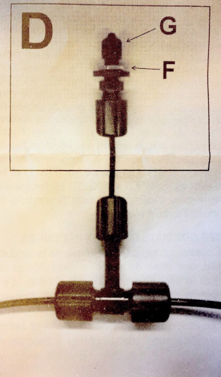
The next step was to do the “plumbing” for the operation of the air shocks. The “kit” that came with the shocks was part number AK18.
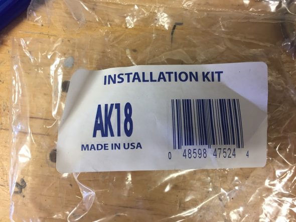
Monroe Shocks Air Fittings Part #AK18
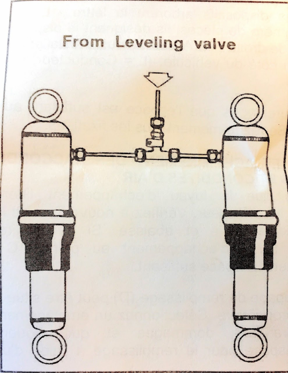
This involves connecting the fitting on each shock to a central “T” fitting roughly in the center above the axle.

“T” Air Fitting

Air Lines to Shocks
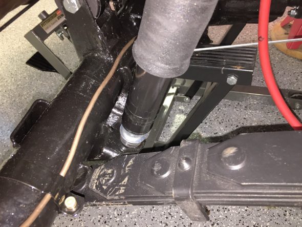
I temporarily secured the air hose to the fuel pipe with plastic zip ties. Before painting the car, but after the axle is removed I will install a few permanent clips to secure the hose to the chassis.
Air Hose from LH shock to -T- Joint
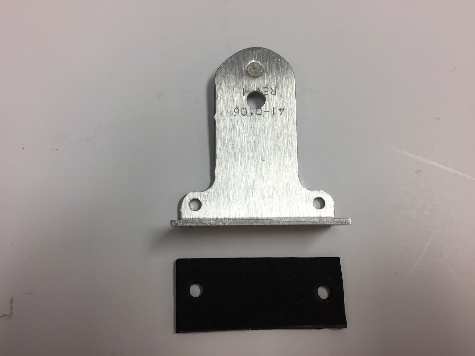
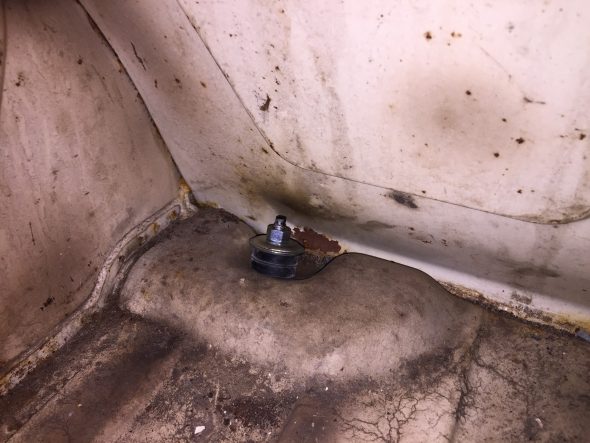
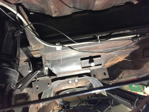
From the “T” fitting a single air hose runs to the the Schrader Valve (like a bicycle or car tire valve) used for filling the system. I decided to locate the schrader valve in the boot behind the casing assembly on the LH side of the luggage compartment. I made a little bracket from some scrap aluminum that I had and mounted it to the floor of the compartment using two #10-24 x 1/2″ machine screws into nutserts that were installed in the floor. A 3/16″ hole was also drilled into the floor to allow the air hose to enter the compartment from below. A small rubber grommet was used to protect the air hose and to keep out moisture.

Schrader Valve Aluminum Mount and Rubber Gasket
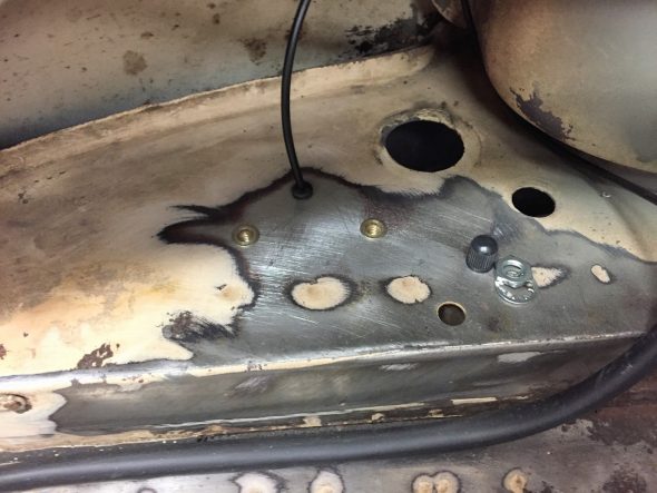
Schrader Valve Mount NutSerts and Rubber grommet for air hose

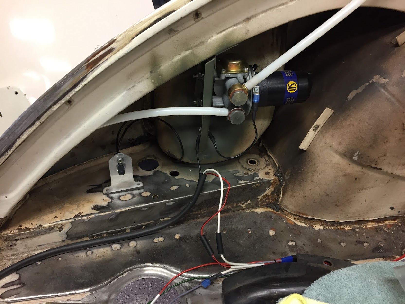
Schrader Valve Mounted in LH Boot Compartment
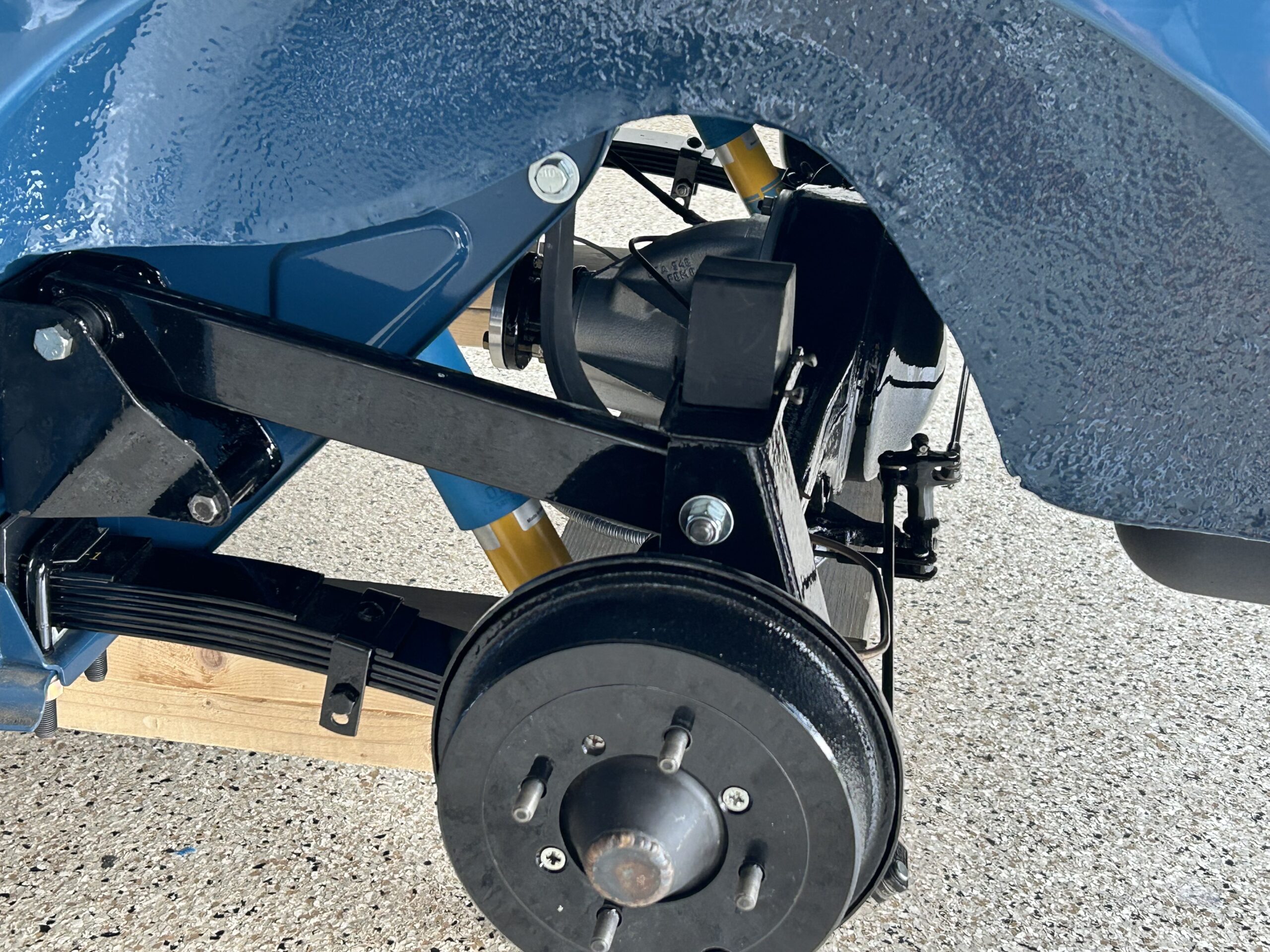
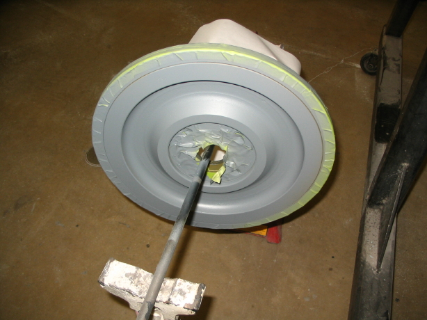
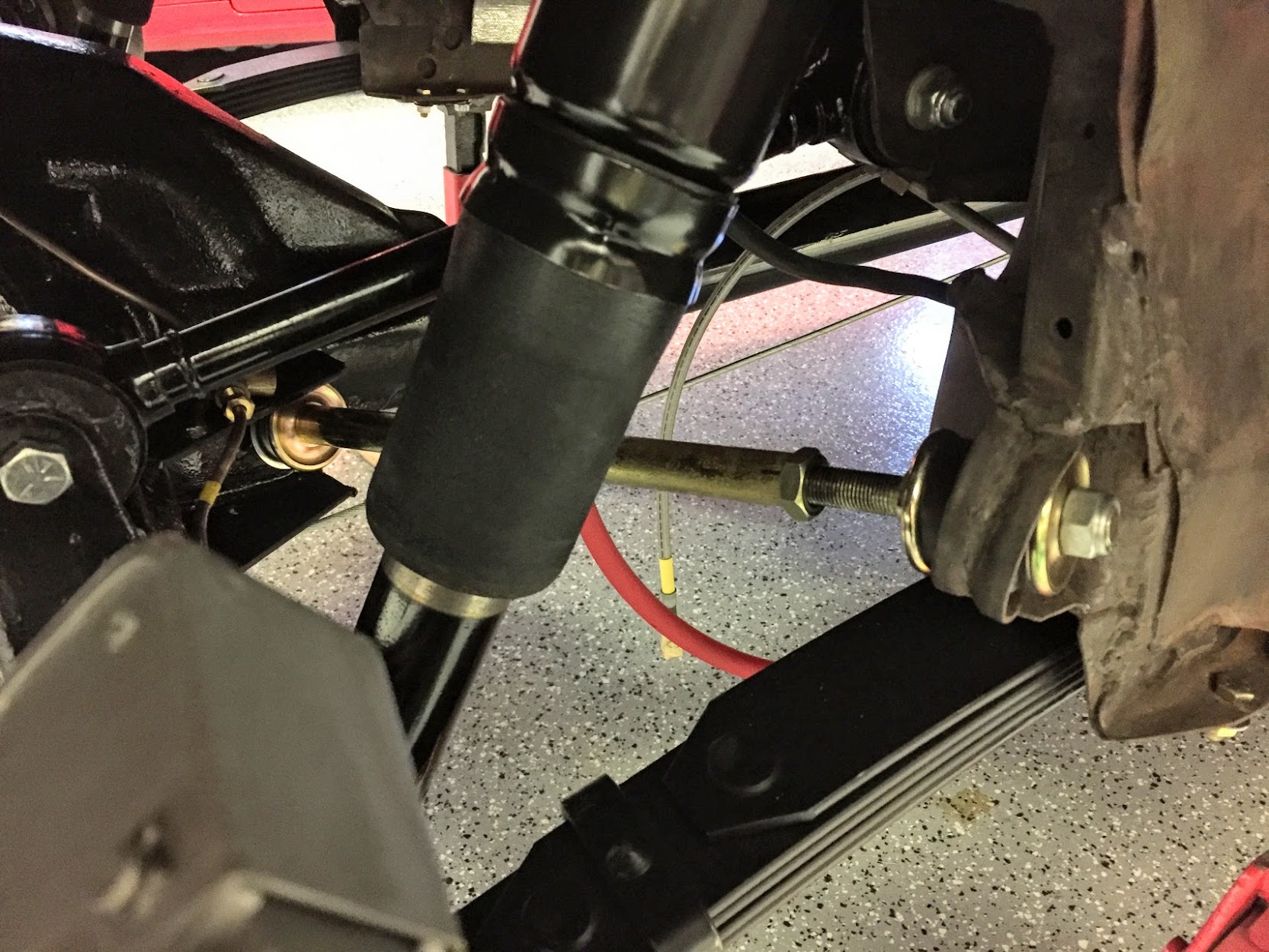
Following installation I tested the system by filling the lines with 90 lbs. of pressure. Everything held tight with no leaks. I then backed the pressure out to 20 lbs. and that is what I will try initially based on the recommendation of Mike Eck. As one can see in the image below, there is approximately 1/2″ of unpainted surface on the shock tube which was the result of the expansion of the shock piston due to the air pressure.
Shock Adjustment with Air Pressure
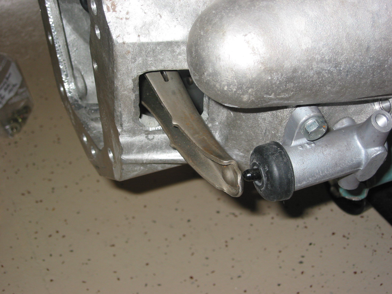
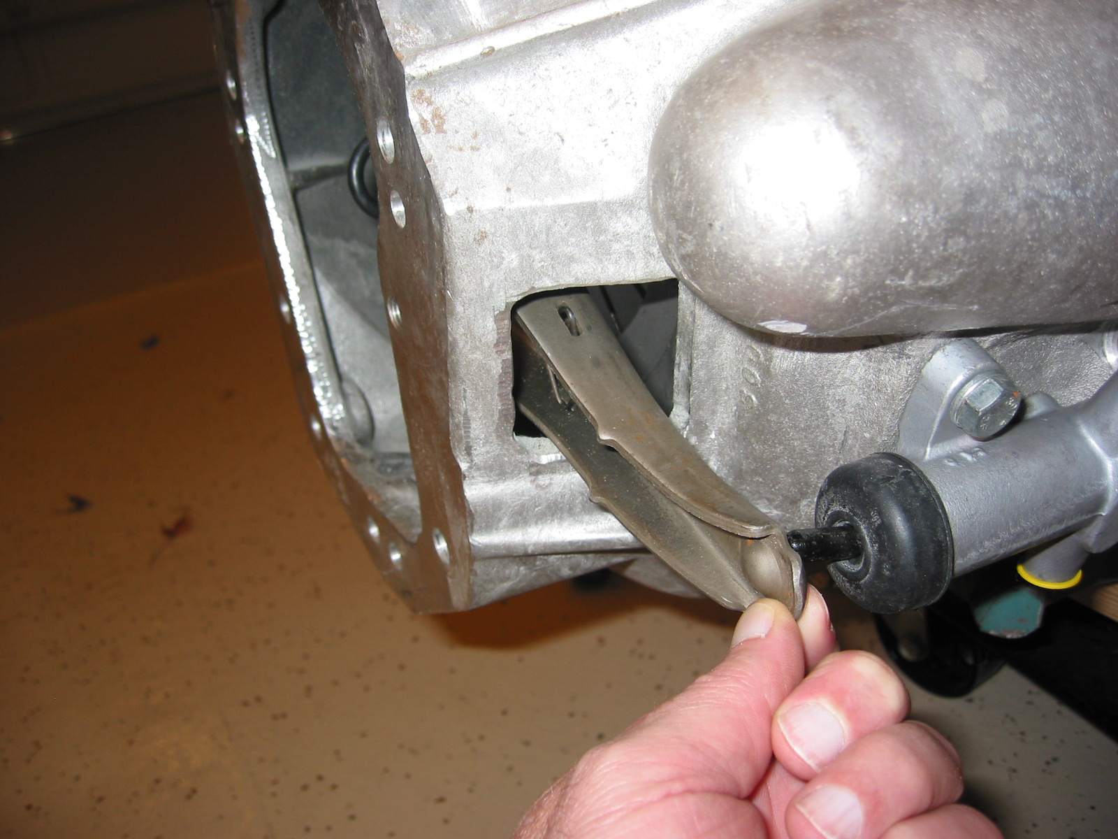
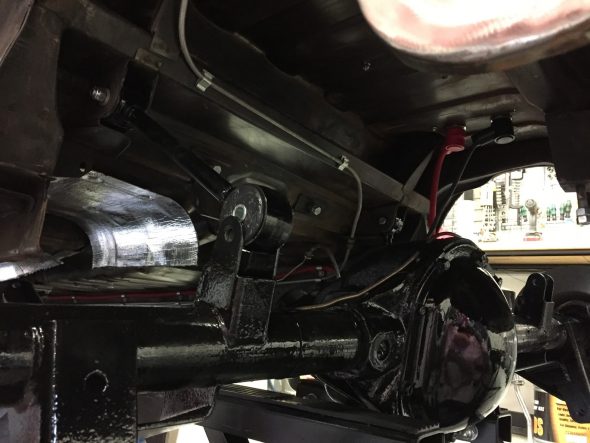
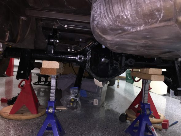
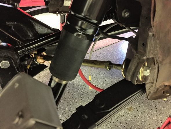
Panhard Rod Installation
As can be seen in the image above the panhard rod was the next component in the rear suspension to install. I used polybushes rather than rubber for the panhard rod and just as Eric Kriss had reported, the polybushes are simply too wide to allow mounting of the unlock nuts on the end of the threaded rod. I ended up cutting one bush in half with a hack saw blade and fit one half on each outer end of the rod. Hopefully, this work satisfactorily.
Again, as recommended in the Service Manual I left the nylock nuts loosely fitted and will not tighten until the weight of the car is on the ground. I also loosened the adjusting piece with a wrench. The Manual offers directions on the alignment procedure for the panhard rod once under load:
“Place a straight edge across one rear tire and check the distance to the flange of the chassis side member at the point at which the rear spring centre clamp is bolted; repeat for the other side. The point of the chassis side member flange at which the dimension should be taken is between the two bolts which secure the rear spring centre clamping plate.
The dimension at each side (A, Fig 6.) must be the same. If they are not, adjust the length of the panhard rod until the two dimensions are equal by rotating the panhard rod tube with a pair of grips. Fully tighten the securing nut at the rear axle bracket end and recheck the adjustment. Finally, tighten the nut locking the adjusting pieces the panhard rod tube.”
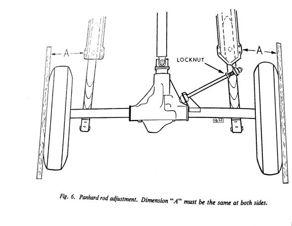
Panhard Rod Adjustment
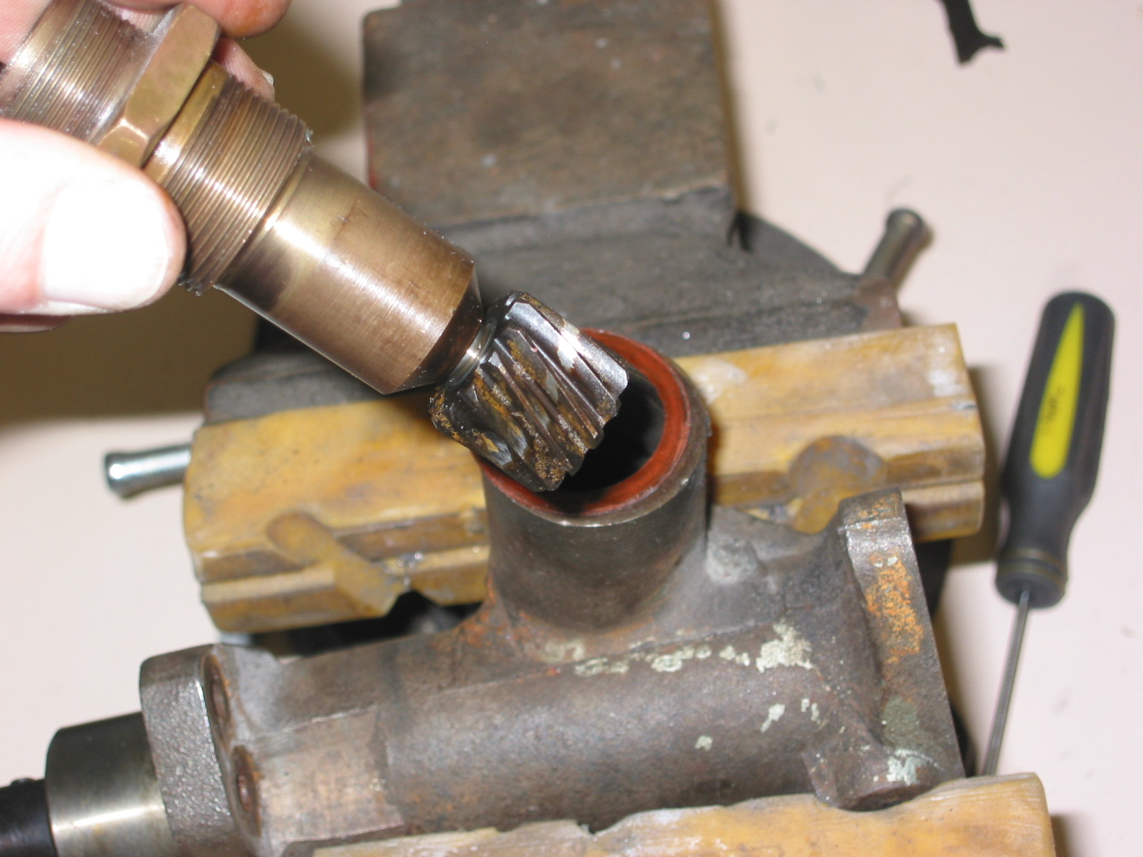
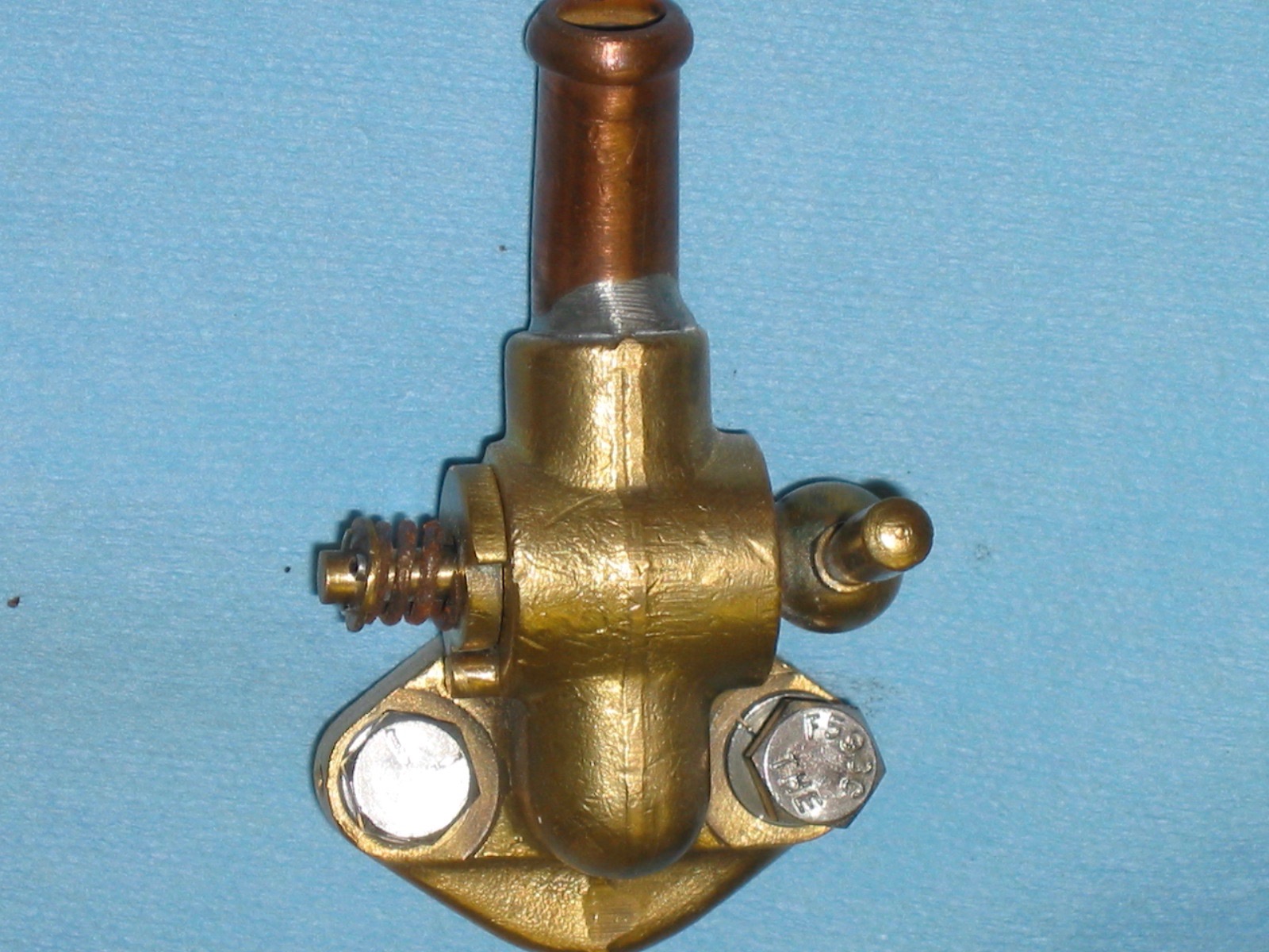
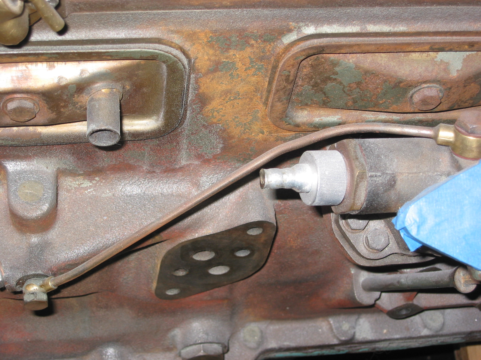
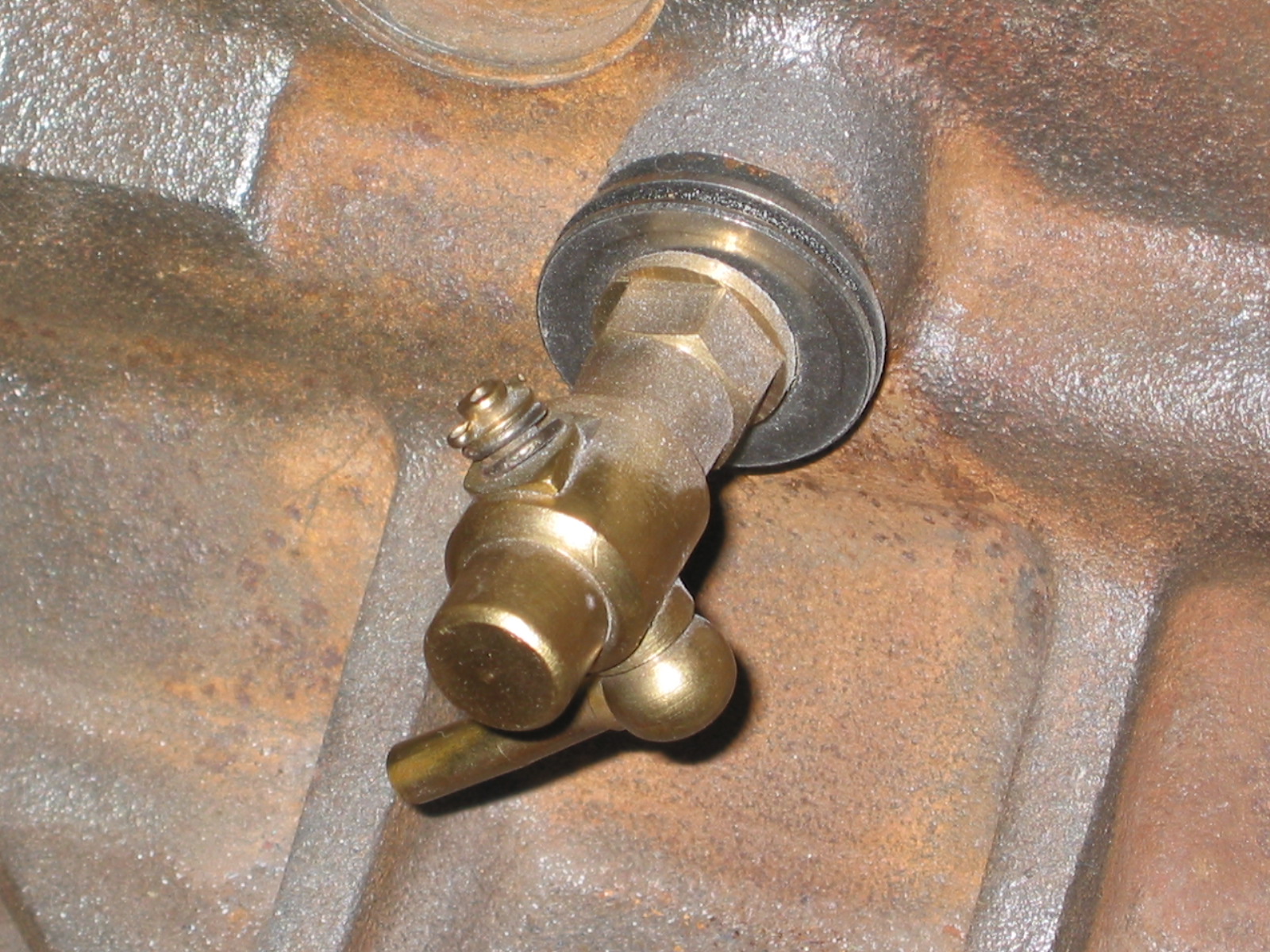
Rear Differential Lubricant
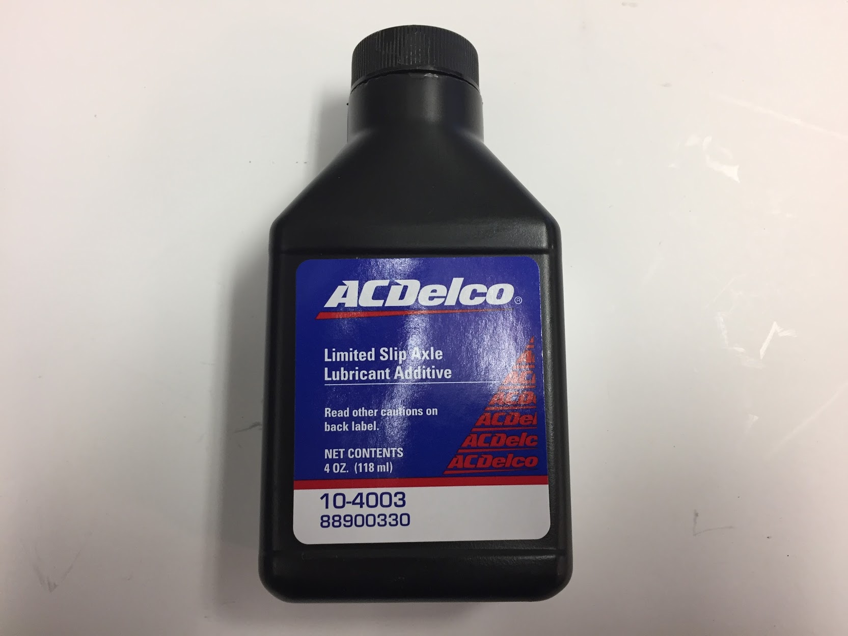
With everything related to the rear axle and suspension in place, the last step in the process is to add the differential lubrication. Mike Gassman, of Gassman Automotive recommended using an AC Delco (General Motors) additive product. It is universally available and I ordered a couple of 4 ounce bottles.
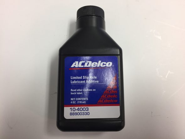
Limited Slip Lubricant Additive
Having spilled a tiny bit of the stuff, I can see why Mike likes to add it. It is very slippery! After pouring the additive in first, I then added SAE 80W-90 Gear Oil. I think most any brand will do. The Jaguar Service Manual calls for 3 1/4 pints, but I always just fill the diff until the oil begins to overflow the fill hole and then I button it up.
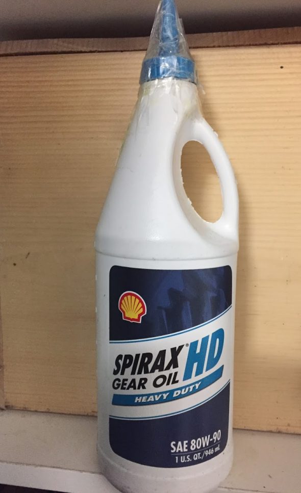
Rear Diff Lube
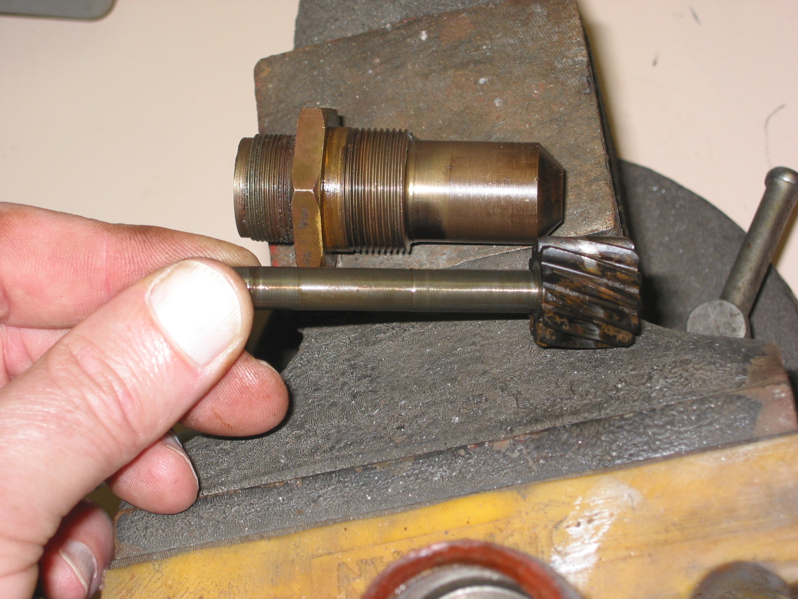
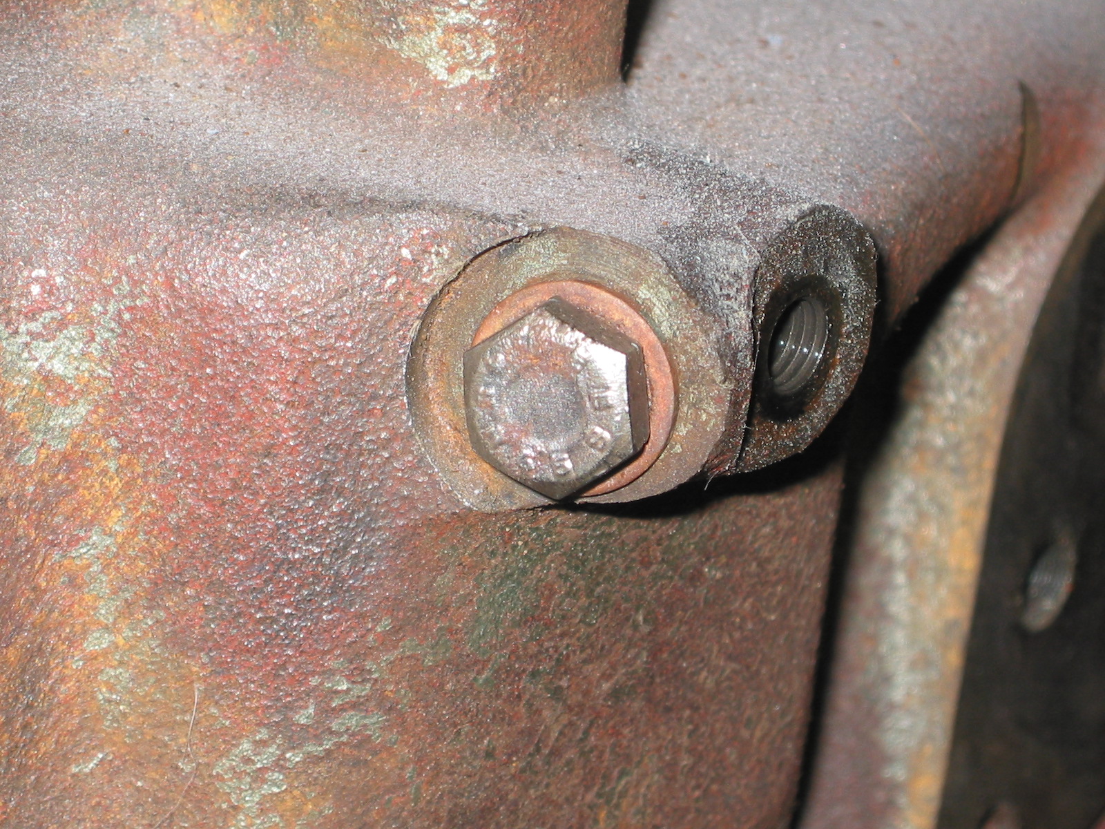
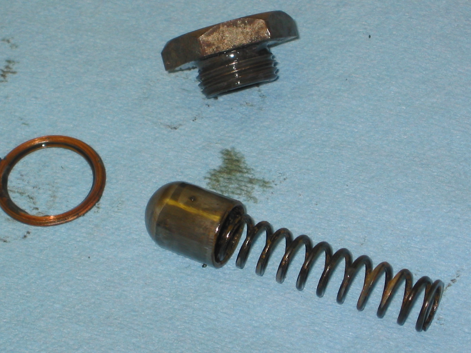
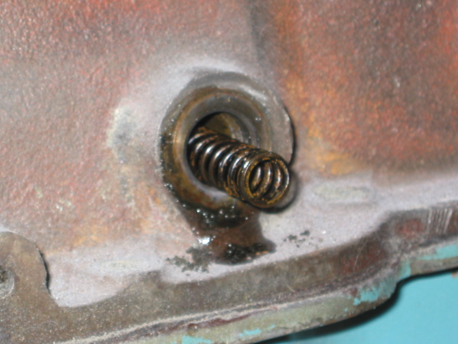
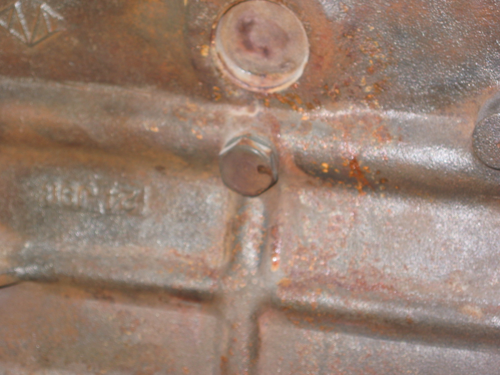
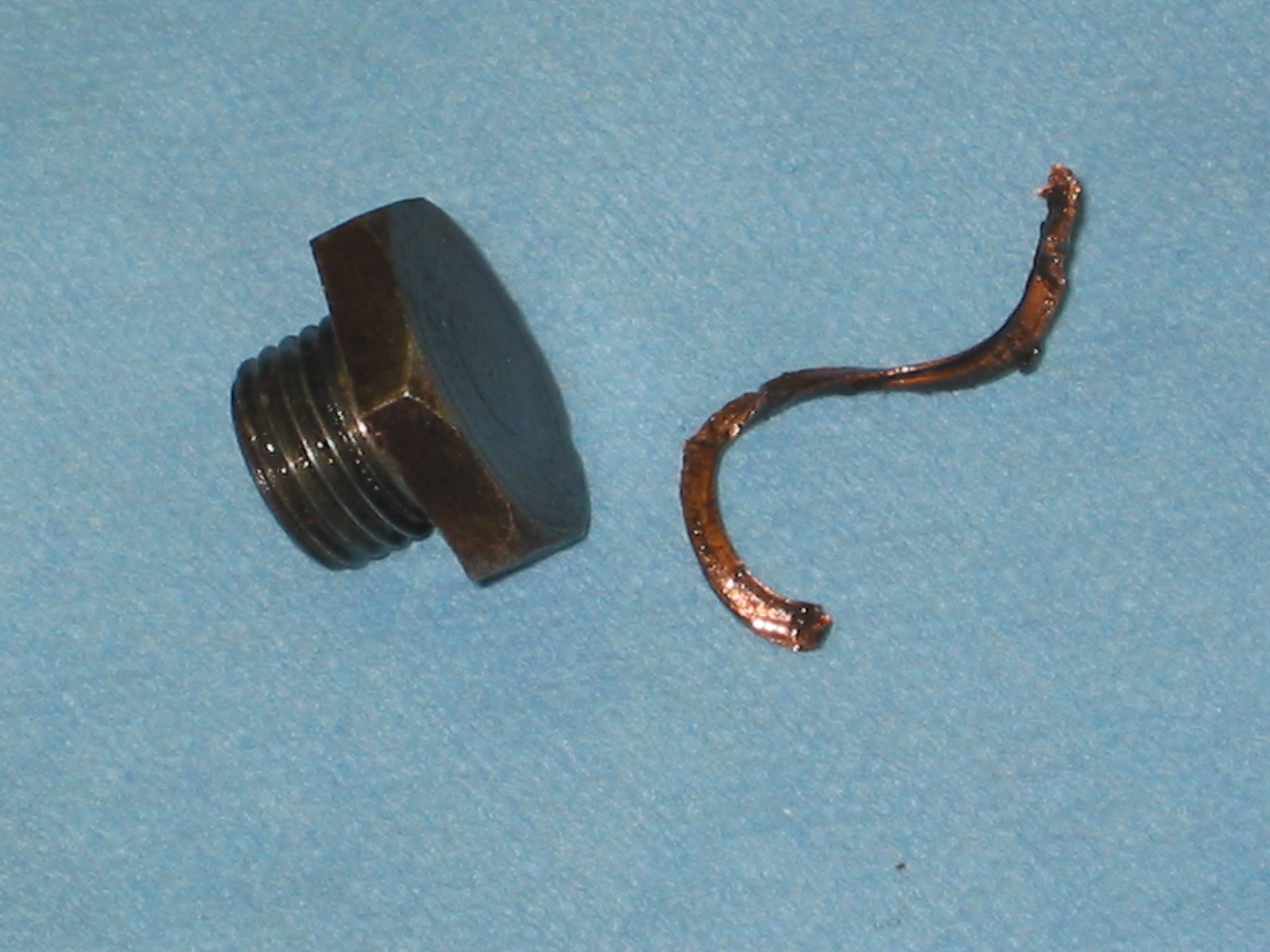
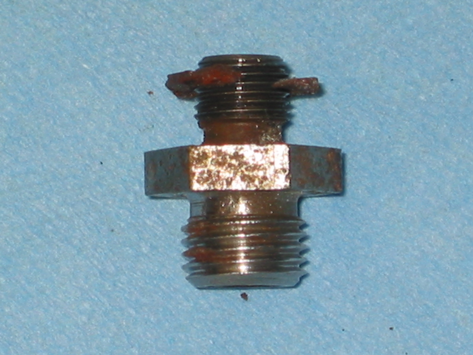
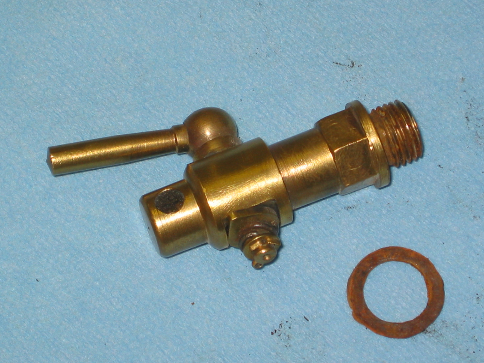
My differential screw plug flat surfaces were stripped on the corners so I replaced it with a new one from SNG Barratt. While the threads match and it “fits” it will not screw-in to the point where the shoulder is flush with the casing. Just one more example of replacement parts not be exactly the same as the originals – not a complaint, just an observation.
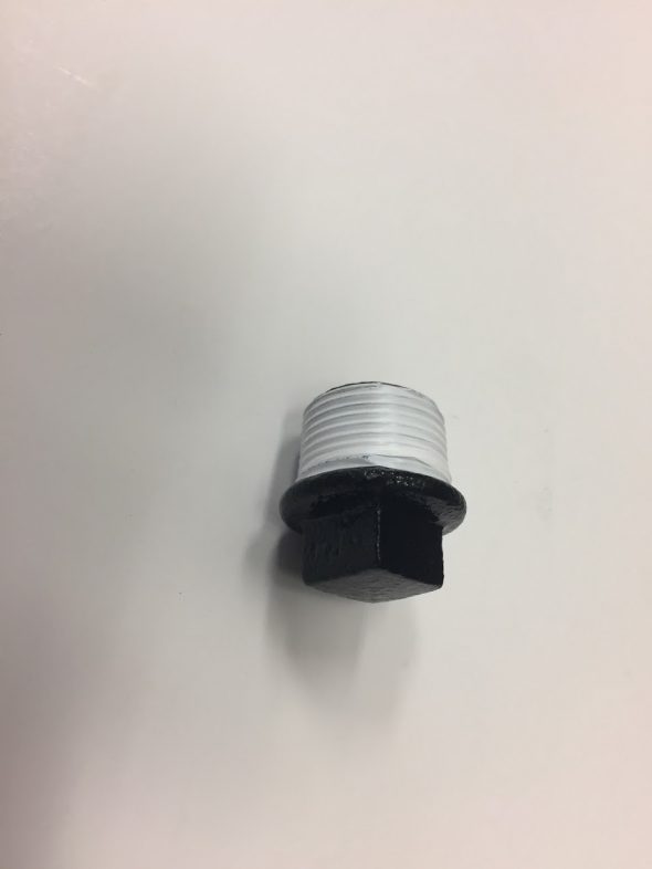
SNG Barratt Diff Plug