Fire in the Hole

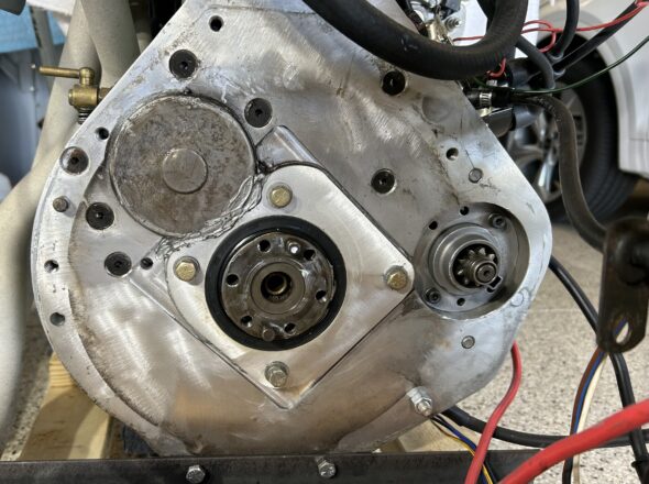
We had planned to run the engine on the starting stand with the gearbox fitted, but thought better of it. First, it would mean that we would have to figure out a way to keep the driveshaft fork in the nose of the gearbox so we would not leak oil out the end. However, more importantly, we wanted to inspect the clutch and the ring gear. So we modified the starting stand to include a mount for the engine rear backplate. 

We then hooked up the choke cable to the carb and we installed a lawn mower throttle cable and slide controller on the control panel and also hooked it up to the carb. These are shown in the video with the link below.

Water was then added to the radiator, Valvoline Racing Oil 20W-50 was added to the engine and some automatic transmission fluid was added to the HIF-44 damper. We then disconnected the coil and spun the engine with the starter until we had oil pressure. After checking ignition timing one more time, and testing for spark at the plugs. It was time to fire it up. It ran pretty well but seemed a bit rich at idle.

After a pause to work on other projects and to wait for parts, we came back to the engine to try to improve the engine’s tuning and to check on the clutch and ring gear.

The clutch had worked just fine but we decided to go ahead and replace the disc and pressure plate since the engine was out of the car. While we were at it, we also made plans to take the flywheel to a machine shop and have the face resurfaced and have the flywheel and clutch pressure plate, or cover, dynamically balanced. That is when things got interesting!

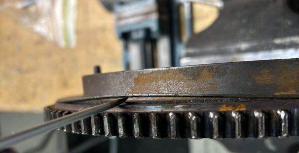
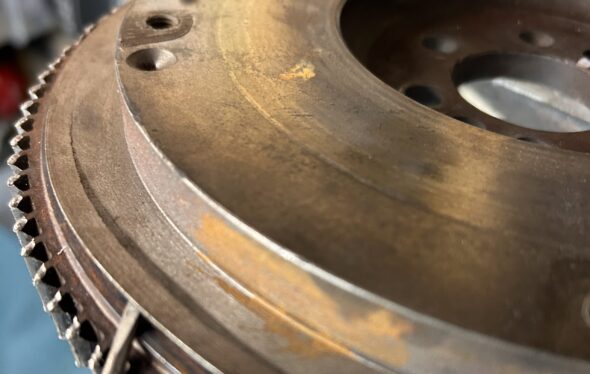
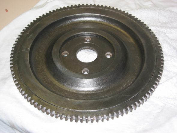
We took the flywheel to Southwest Hydraulics in Venice, Fl for resurfacing, but we got a call from them indicating that the flywheel was “coming apart.” As it turned out the flywheel had been lightened a bt too much and there was very little material between the flywheel lip and the ring gear. See below.

Flywheel delamination

This is going into the trash!

Since they no longer make steel flywheels for the 1275 (aluminum lightened flywheels are available) we searched eBay and located one. It had not been lightened at all which we preferred, but it was not without its problems. One of the clutch cover bolts had been broken off in the flywheel. Fortunately, our friend Randy Forbes came to our aid. Using his milling machine, he first flattened the top of the bolt shaft and then with his drill press using a LH drill bit he was able to remove the broken bolt with no adverse effect. Thank you Randy!

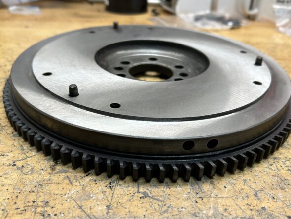
We then took the flywheel back to Southwest Hydraulics for the resurfacing and we also had them replace the ring gear with a new one sourced from A.H. Spares

Flywheel resurfaced

Then it was off to “VAMI” – Venice Auto Marine machine shop where we had the flywheel balanced. Unfortunately, we could not balance the clutch pressure plate with the flywheel because the center hole in the pressure plate was too small to fit on their machine. This should not be a problem as the pressure plate comes balanced by Borg and Beck. The new disc was sourced from Rivergate.

We then reinstalled the flywheel, clutch disc and clutch pressure plate. The flywheel bolts were new and torqued to 4o ft. lbs. A locking tab washer was installed and all the tangs were bent over. The clutch bolts were torqued to 19 ft. lbs.

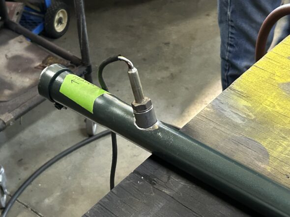
In the meantime, we replaced the metering needle that came with the carb with a “BDL” needle to get some additional fuel at start up without having to rely so much on the choke. Randy Forbes again came to our aid with the installation of our oxygen sensor.

Oxygen Sensor Bung Installed

Randy doing his thing!

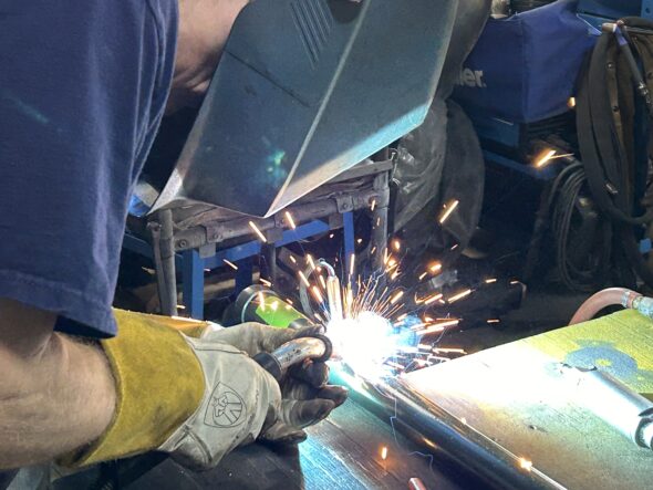
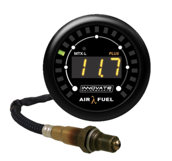
He installed a bung into our new exhaust pipe for the  oxygen sensor so that we could use our newly purchased Innovate Motorsports AFR gauge. This is very helpful in adjusting the fuel mixture at the carb.

Innovate Motorsports AFR Gauge

Before starting the engine a second time we also decided to replace the original-type Lucas starter with the gear reduction starter we had. 

We then started the engine a second time and we were pleased with the changes that had been made. The engine seems to be running well with a static advance of 12 degrees and a full advance of 31 degrees at 3,800 rpm. All of our changes and the first and second running of the engine are included in the Bugeye Restoration Video Episode Sixty. 

https://vimeo.com/953122217/a96f4deab1?share=copy

Episode Sixty includes the following content:

0:35 – Gearbox removal

2:30 – Throttle control

3:35 – Choke cable

4:40 – Engine fluids

6:35 – Priming the oil pump

7:35 – Checking for oil pressure

8:10 – Ignition timing

8:32 – TDC Compression stroke

9:00 – Checking for spark

10:35 – Engine starts!

11:30 – Ignition timing again

12:20 – Marking the distributor setting

12:30 – Gear reduction starter reinstalled

13:10 – Innovate Motorsports AFR gauge

14:08 – Engine running again

14:45 – Engine storage until it goes in the car

The exhaust was then removed along with the intake manifold, the HIF carb, and the exhaust header. This was done because we are sending the exhaust header to Jet-Hot for a ceramic coating. We have now covered the engine and pushed her to the side. The good news which is really too good to believe, and surely will not last, is that we have no oil leaks!

Wow, we started this engine work back in September of 2023. Considerable time has passed but we were continually diverted to work on other parts of the restoration. Other than coating the exhaust header we believe the engine is now complete. Hopefully, by Christmas she will be reunited with the car and it will be as easy as installing the engine and gearbox and taking the car for an initial run!


Clutch/Gearbox and Propshaft Assorted Modifications

The system consists of the clutch, gearbox, overdrive, and propshaft. The original driveline system included the following:

Clutch: 10” Borg and Beck hydraulic

Gearbox: “side-shift” 4 speed

Overdrive: Laycock de Normanville electric

Propshaft: Hardy Spicer universal joints

Flywheel: 28 lb.

Driveline Modifications

Toyota 5 Speed Conversion

Although I always enjoyed the Laycock de Normanville electric overdrive in my car, I knew my tranny needed to be rebuilt. Rather than go that route, I took advantage of Smitty’s five speed conversion kit and installed a Toyota gearbox in the Bloody Beast. The Toyota Gearbox is quite a bit lighter and folks say that it runs  a bit cooler than the original box.

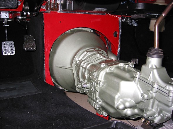
Gearbox and Bell Housing Installed

Gearbox and Bell Housing Installed

You can use a number of different Toyota gearboxes from the non-turbo Supras or from several of the 2 wheel drive pick-ups. I used a W57 1998 Toyota Tacoma 4×2 VIN# 4TANL42N2WZ094878. Details are available in the restoration blog, but this pdf document put together by Tracy Drummond is very helpful. Drummond Five speed gearbox conversion.

The kit includes several custom components including a bell housing casting unique to the conversion.

The kit is no longer available from Smitty, but Pete Delaney now handles the product. His contact information is as follows as of July 10, 2012:

Stephanie & Pete DelaneyHealey 5 Speed
P O Box 561
Harrisburg, NC 28075
704-455-2585704-455-8504 FAX
Healey5Speedaol.com

Clutch Conversion

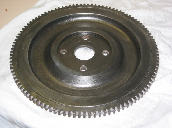
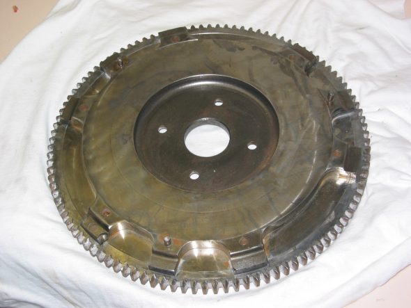
Many who have the early 3000s and who complete the 5 speed conversion also adopt the BJ8 9/12″ diaphragm clutch. It is less demanding on the left leg muscles. I went ahead and made this conversion while I was at it. This also requires using a BJ8 flywheel. I obtained a 24lb. lightened flywheel from Bill Bolton.

BJ8 lightened Flywheel

BJ8 lightened Flywheel

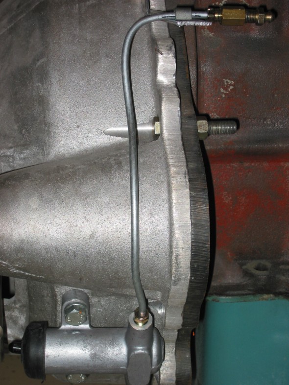
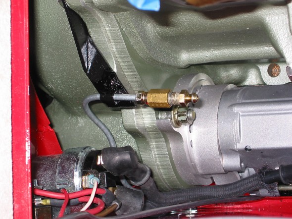
Slave Cylinder Bleeder Pipe Extension

Anyone who has bled a Healey slave cylinder knows that the bleed nipple is not exactly easy to get to. Doug Reid aka “Mr. Finespanner,” fabricated an extension for me that makes the job much easier with the bleeder actually accessed from the engine bay. This has now become a popular item used by many aficionados.

Slave cylinder bleeder

Slave Cylinder Bleeder Extension

Slave cylinder bleeder extension

Slave Cylinder Bleeder Extension

Custom Propshaft

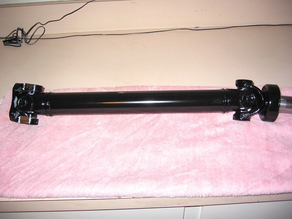
Installing the Toyota 5 Speed does require making up a new propshaft, which I had done at a local speed shop. The propshaft does need to be balanced prior to installation.

Propshaft

Propshaft


zz

Chapter 32 – Cleaning and Trial Fitting


October 27, 2006

Jeremy’s Rotisseri

More Rotisseri Images –  The rotisseri really does make working on the underside of the frame so much easier. These are a few additional images of the assembly at work.
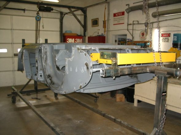
rotisseri 7
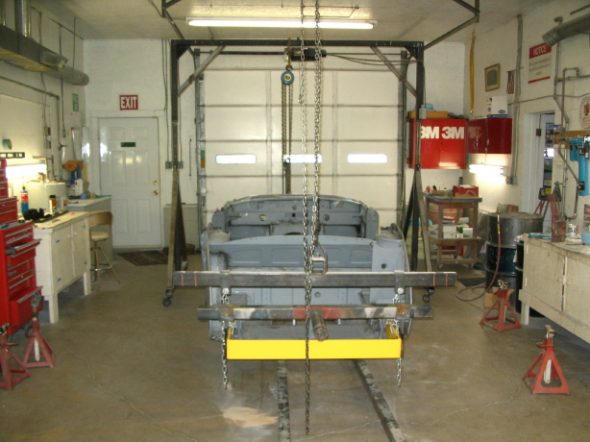
rotisseri 6
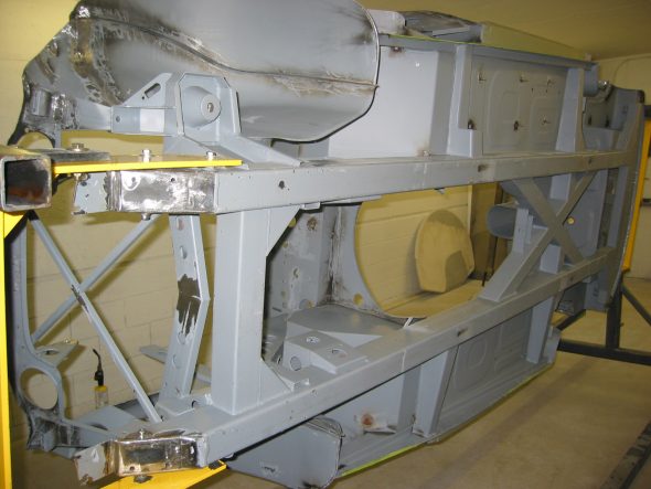
Rotisseri 9
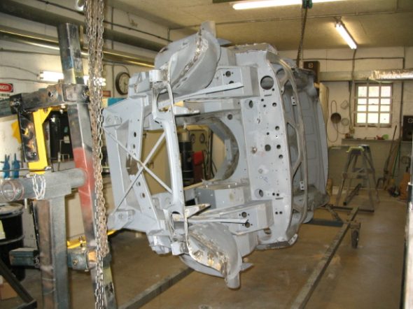
rotisseri 1
anti-sway bar bracket


November 7, 2006

Jeremy’s Bodywork

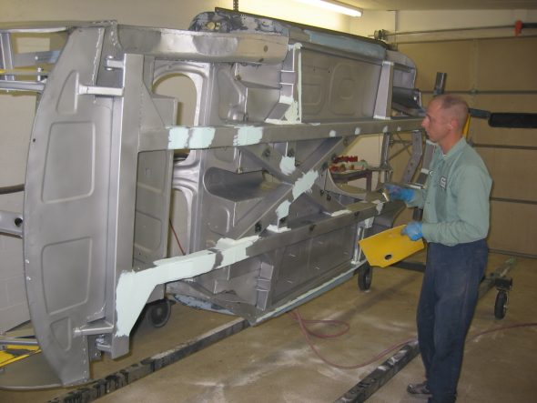
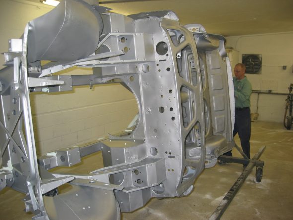
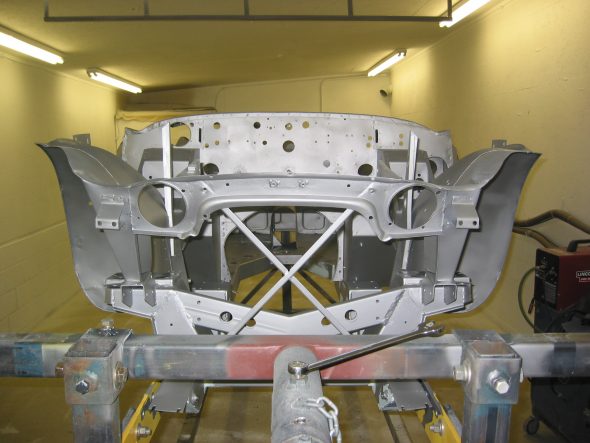
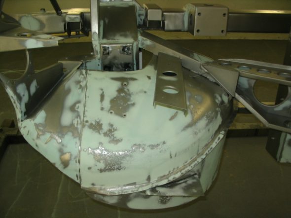
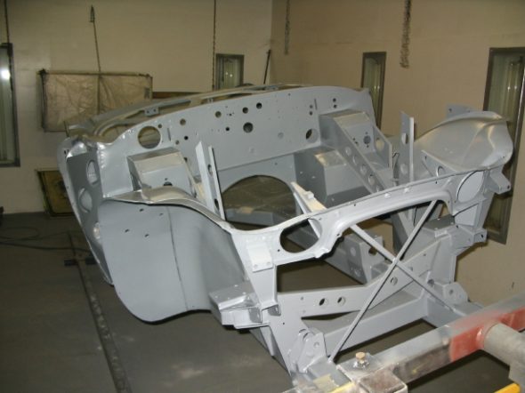
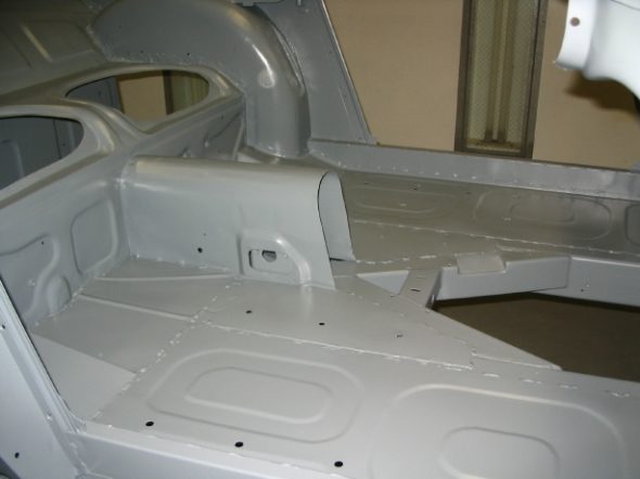
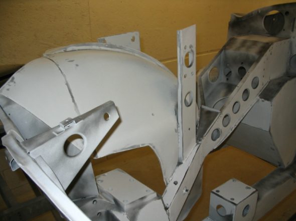
Jeremy has continued to work hard on the final work on the frame/tub. He has done a very nice job with the judicious use of filler to give a nice finished appearance to the frame as if it was the body! Pitting on the outside of the kick panels and on the underbonnet inner fenders just looks great.
Frame blasted clean 1
Frame blasted clean 9
Frame blasted clean 10
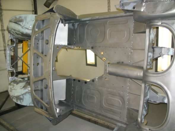
fill primer 3
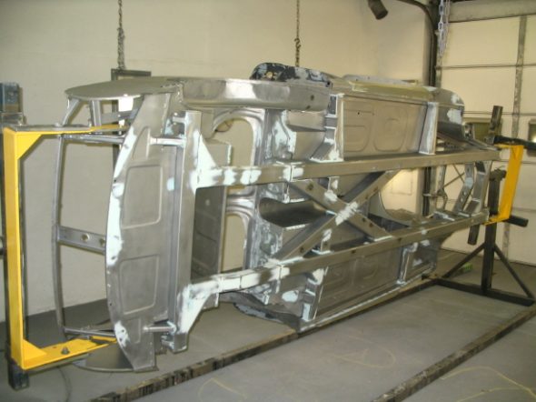
frame bodywork
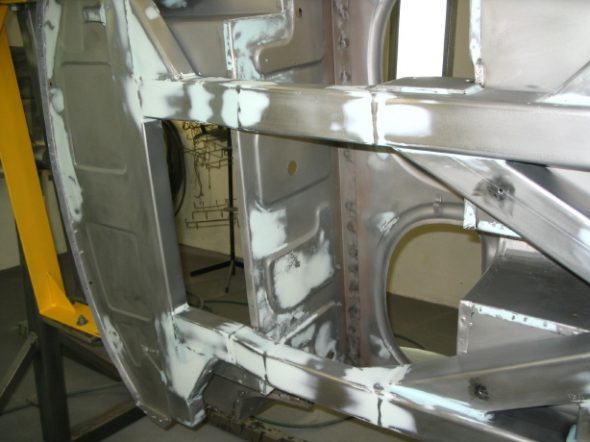
frame bodywork 3
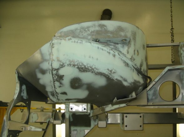
frame bodywork 2
frame bodywork 4
frame epoxy primer 1
fill primer 4
Final sanding 1
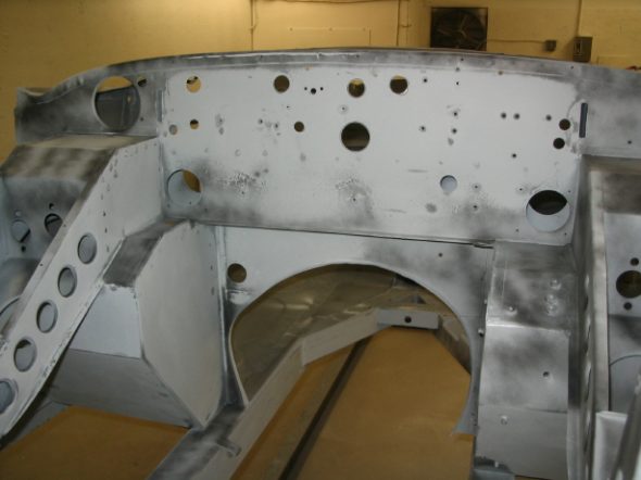
Final sanding 2
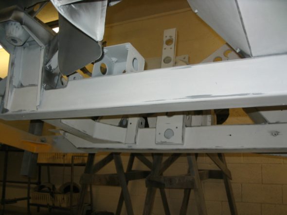
Final sanding 3
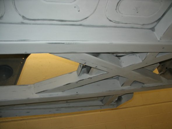
Final sanding 4

November 12, 2006

Engine Rebuilding

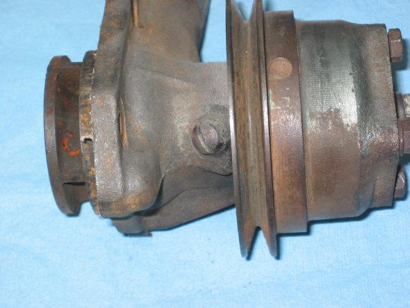
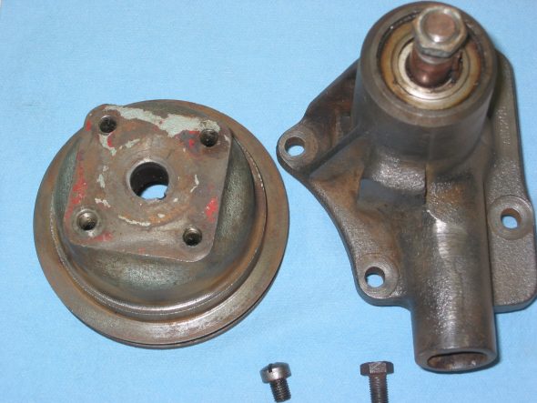
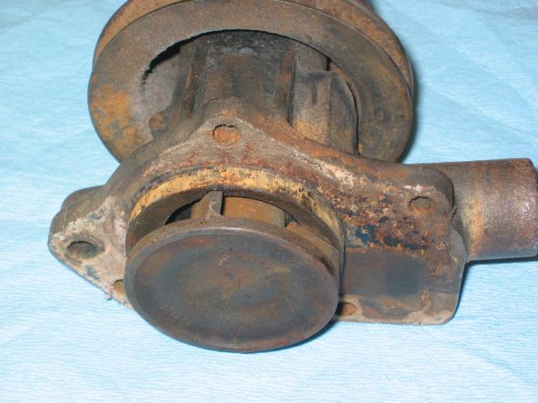
Water Pump – Although Jack Harper will be doing the engine rebuild, there are some items that I can take care of before I take the motor to him. I already sent the rocker arm assembly out for rebuild, and today I queried the internet healey list about their thoughts on the water pump. Was I better to rebuild my own or purchase an after market replacement? Those whose opinions I have come to count on recommended rebuilding my own and perhaps purchasing a new one to have as a spare. Bill Bolton, Peter Caldwell and Joe Curto were suggested as possible rebuilders. I had experience with all three but decided to call Peter since his lever arm Armstrong shock rebuilds will be on my car and because so many rave about the quality of his work.  He indicated that his company didn’t “officially” do water pump rebuilds, but they were getting ready to do a number of them and that I should send mine along His rebuild would be $75.00. I took mine off the motor – four nuts on studs and took the pully off the pump shaft. That required the use of the slide hammer, but was easily accomplished.
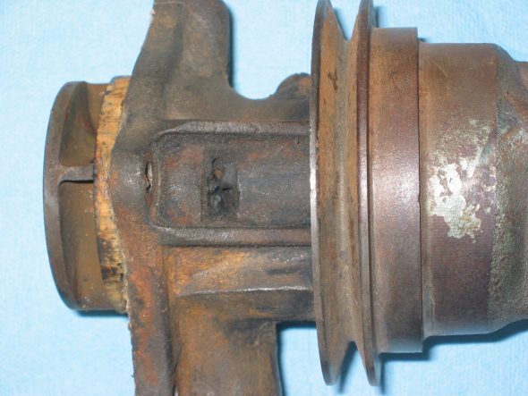
Water pump 1
Water pump 6
Water pump 8
Water pump 5

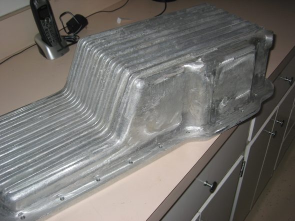
Aluminum Oil Sump – I ordered an aluminum oil sump from British Parts Northwest. After researching the sumps available from various suppliers. Others reported that the BPN sump did not require modification to the oil pump because it is a little deeper than the others. Of course, that also means it protrudes lower in the frame, but since my motor mounts are ¼” high I concluded that it would work best. Unfortunately, it arrived in pretty rouh shape with grinder marks on the exterior and some casting depressions. I sanded the body until most of the grinder marks were eliminated. Jeremy will glass bead blast and we will put a few coats of clear paint on it for protection.
aluminum oil sump 2

November 24, 2006

Jeremy’s Painting and Bodywork

Suspension and other little bits   To take a break from sanding the frame, Jeremy turned again to finishing some of the smaller parts that are to be painted gloss black. The following images show some of the work.
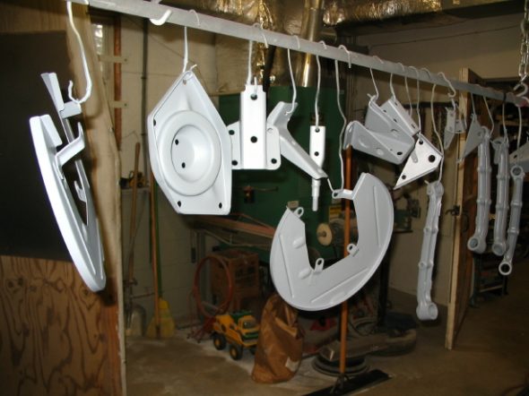
small primed parts 2
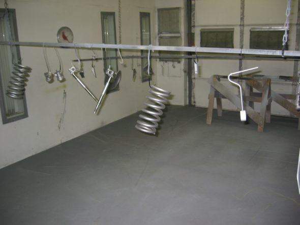
media blasted parts 2
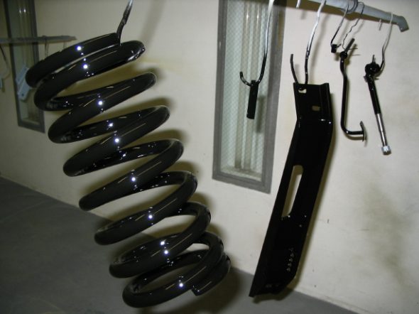
small parts black 1
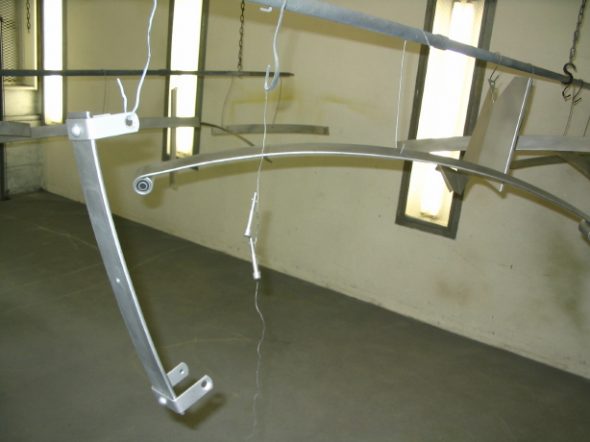
rear springs blasted 1
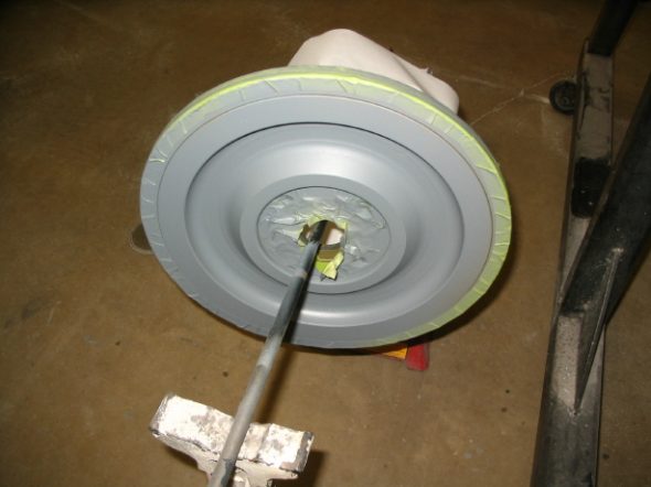
flywheel ready to paint
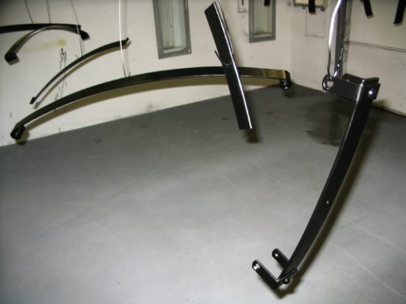
Rear Springs painted 1

Rear Leaf Spring Assembly – The leaf springs were painted semi-gloss. I put a layer of teflon tape between each of the leaves to provide for smoother action between each of the leaves. It should help to eliminate creaks and moans later. The finished products looked very nice.
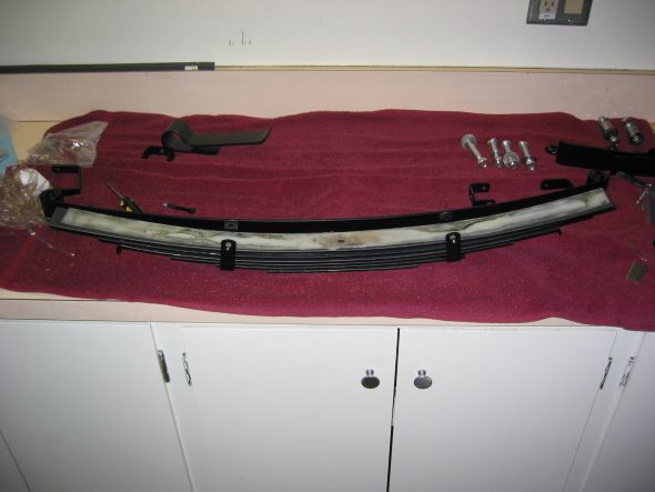
Rear spring glide strips 1
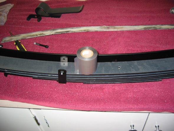
Rear springs teflon tape
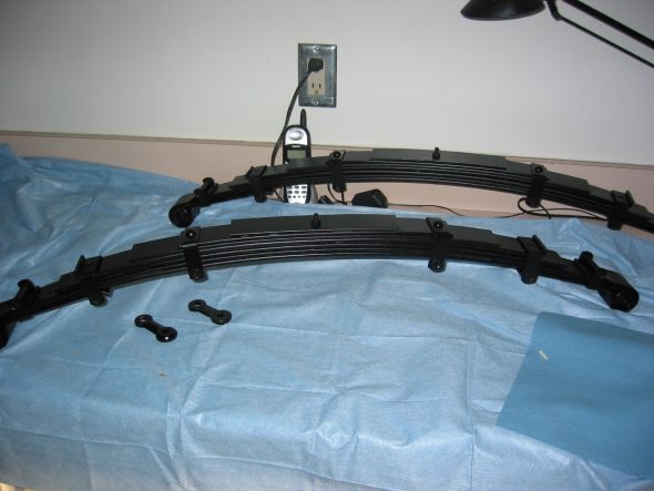
Rear springs completed

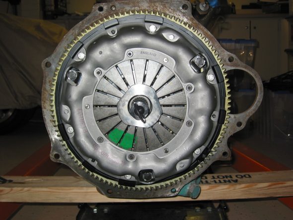
Smitty Toyota Transmission Conversion and Clutch Assembly – I wanted to see how the conversion assembly was going to fit so I decided to rmove the gearbox from the bell housing and set things up. The lightened flywheel from Bill Bolton had been cleaned up and painted just for some rust protection. I inserted the aluminum pilot bushing with bearing pressed in by using my lead knock-off hammer and soft drift to keep from damaging the aluminum.
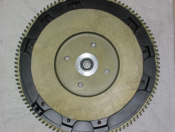
Flywheel Smitty Pilot Bearing

Crank Rear Oil Seal – I will be purchasing an improved crank rear oil seal which will require some modification of the backplate, but for now I just wanted to see how things were going to fit, so I used the backplate as it was. I then fit the flywheel to the crank. Although not in the image below, I will be using the flywheel bolt lockdown tab washers.
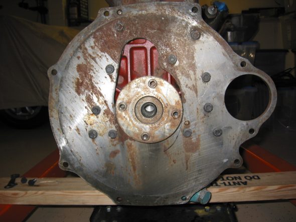
Engine Backplate
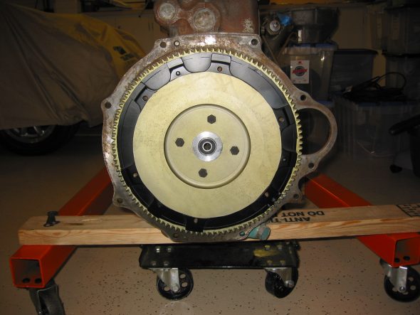
Flywheel installed 1

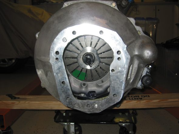
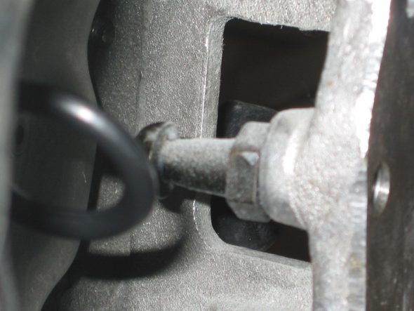
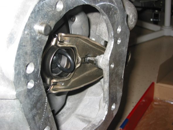
Then I installed the Pressure plate using the Smitty supplied clutch disk (thicker than stock Toyota) and centered it using the alignment tool supplied in kit. After installing the bell housing it became obvious that the throw out arm did not have sufficient travel without hitting the back edge of the opening in the housing. I will add some length (others have suggested about 3/16” to the pivot fulcrum to gain the travel required.
Clutch plate assembly
Bell housing installed
Clutch arm pivot 2
Throw out bearing clutch arm 1
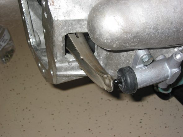
Throw out bearing clutch arm 2
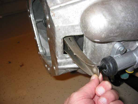
throw out arm 1

November 27, 2006

Back to the Engine Work

Tach Drive Housing – Detached the tach drive housing from the block. Three ¼” x 7/8” Hex head bolts with flat and lock washers. As per the manual, pulled out the gear drive with a 3” x 5/16” bolt attached to the threaded hole in the drive. Will need to install new rubber seals in the unit.
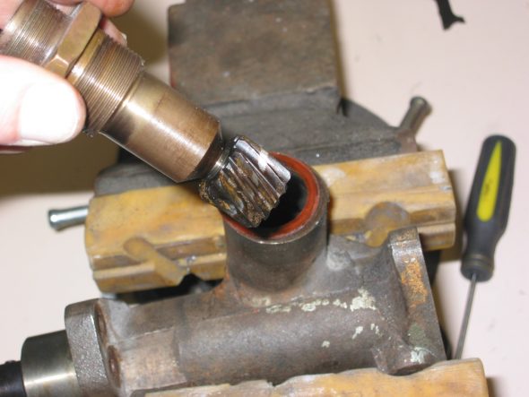
Tach Drive assembly 1
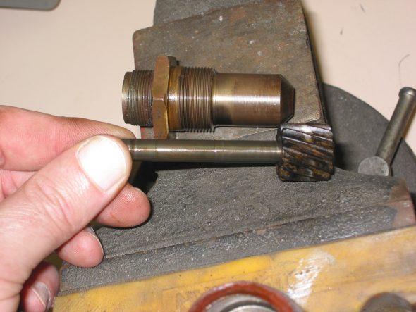
Tach Drive assembly 2

Tappet Cover Plates – There are three covers. The rear cover with the breather pipe is secured with one 1 ¼” x 5/16” hex head bolt with a copper washer and a cork gasket. The center cover is also attached with one 1 ¼” x 5/16” hex head bolt with copper washer and cork gasket. The front cover which is much heavier to support the weight of the generator is secured with five ¾” x 5/16” hex head bolts with copper washers.
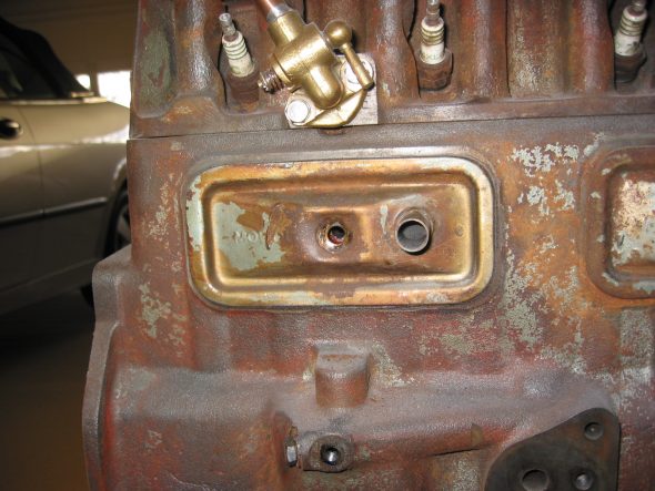
Rear Side Cover
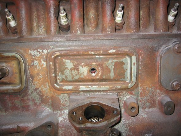
Center Side Cover
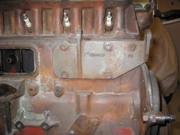
Front Side cover 1

Heater Water Valve –  Secured by two 5/8” x ¼” hex head bolts and washers.
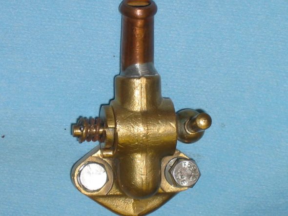
Heater water valve

Blanking Plate – Located on the right side of the motor. Two hex head bolts 5/8” x 5/16.” Course threads with copper washers.
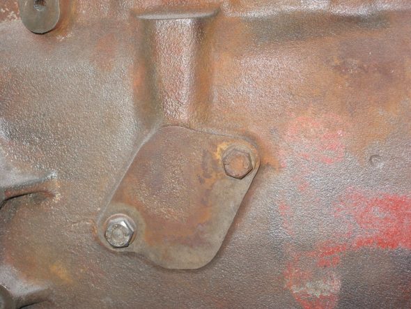
Blanking Plate

Oil Pipe Fitting, back side – One hex head bolt, 3/8” x 5/16” with copper washer.
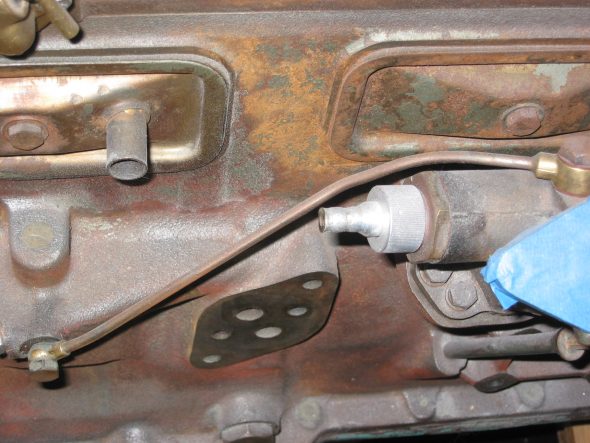
Oil Feed Pipe
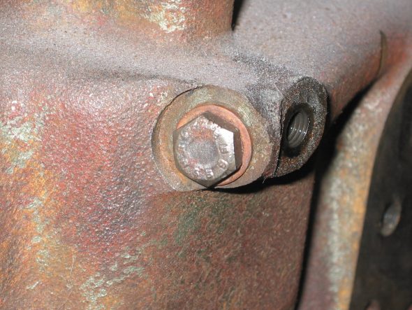
Oil Feed Bolt

Oil Pressure Relief Valve – One 1 1/8” (wrench size) hex head bolt x 3/8” long. Copper washer with spring and cup.
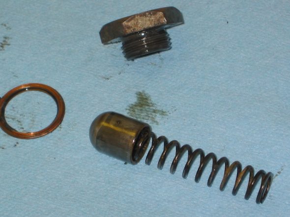
OIl Pressure Relief Valve 2
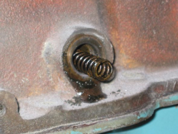
OIl Pressure Relief Valve 1

Plug for Oil Filter Feeder Hole – Right side of block. One 7/8” (wrench size) hex head bolt 3/8” long, with copper washer.
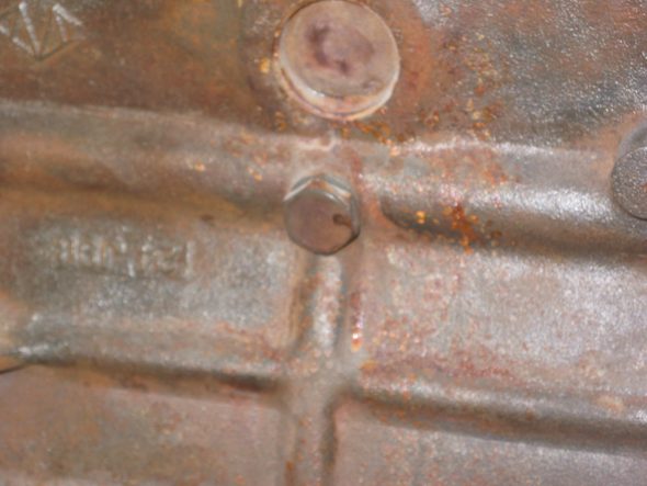
OIl Filter feeder hole plug 1
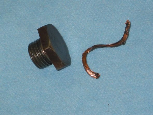
OIl Filter feeder hole plug 2

Union for Oil Gauge Pipe – Right side of block. Nut with pin hole. Fiber washer.
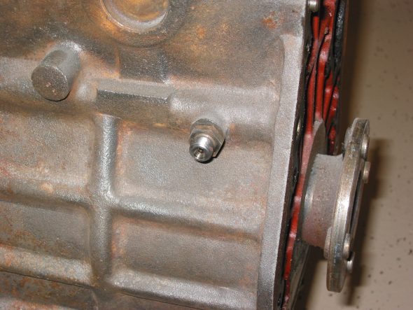
Oil Pressure Pipe Union 1
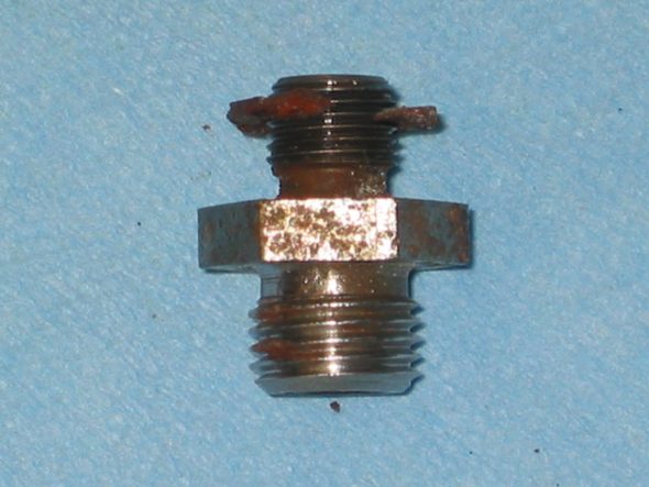
Oil Pressure Pipe Union 2

Block Drain Tap – Brass with fibre washer.
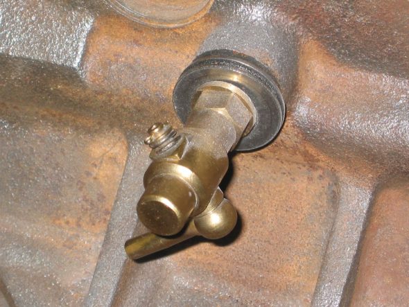
Drain Tap 1
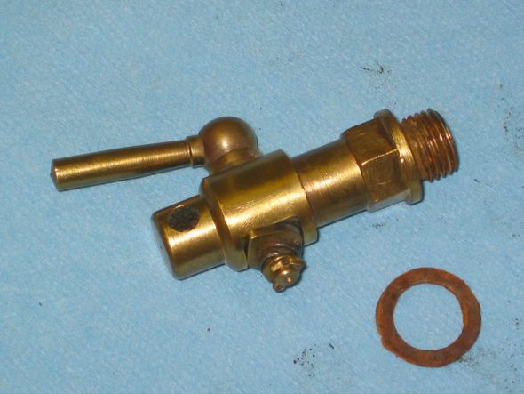
Drain Tap 2

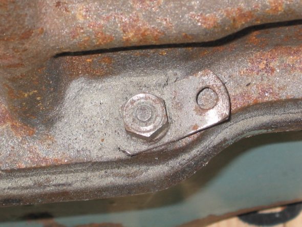
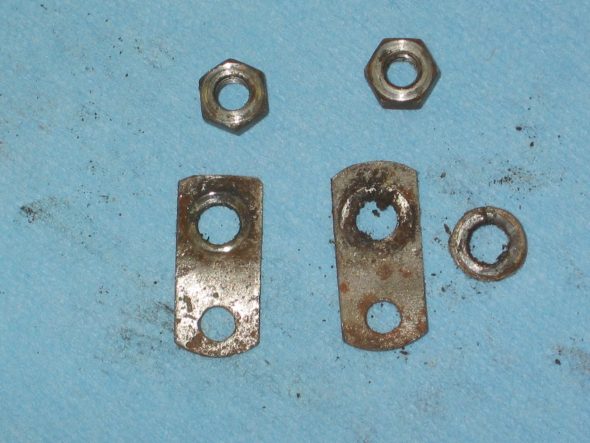
Carb Drain Pipe Brackets – Located at the second and seventh oil sump mounting bolts from the font of the block. ¼” nuts used to secure the clips.
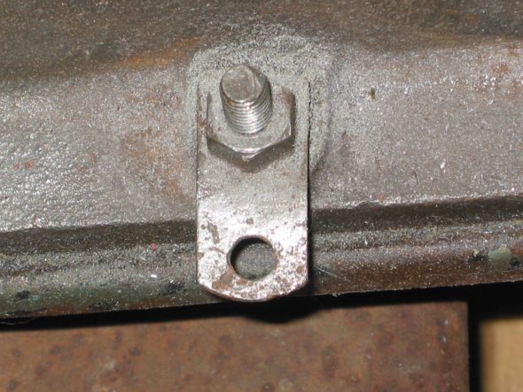
Fuel Drain Pipe Clip 1
Fuel Drain Pipe Clip 2
Fuel Drain Pipe Clip 3

November 27, 2006

Jeremy’s Painting and Bodywork

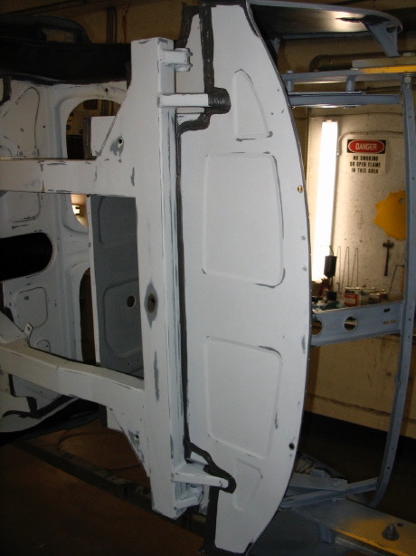
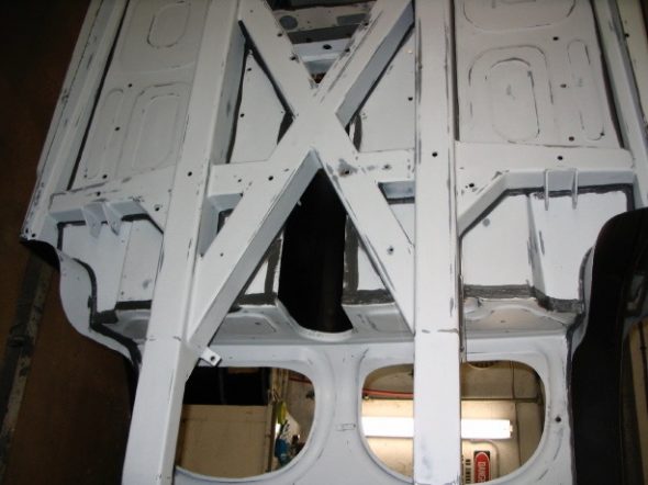
New Seam Sealer and Prep for Chip Protector   Jeremy finished the sanding work and installed seam sealer. 
Seam sealer finished 1
Seam sealer finished 2

Seam sealer 4
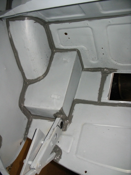
Seam sealer 1
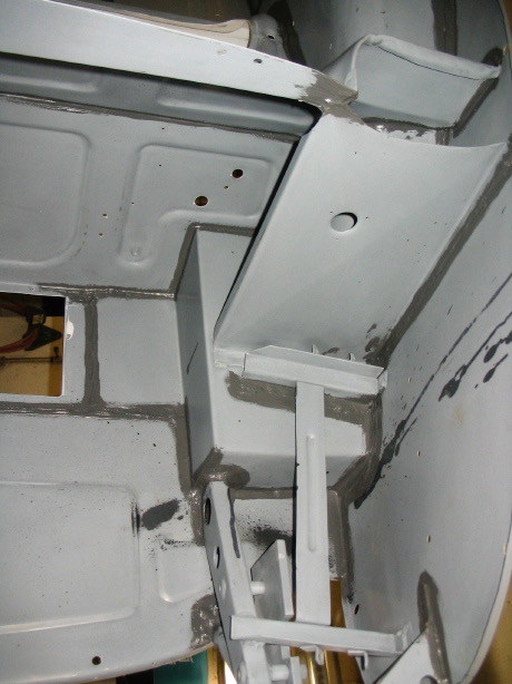
Seam sealer 2
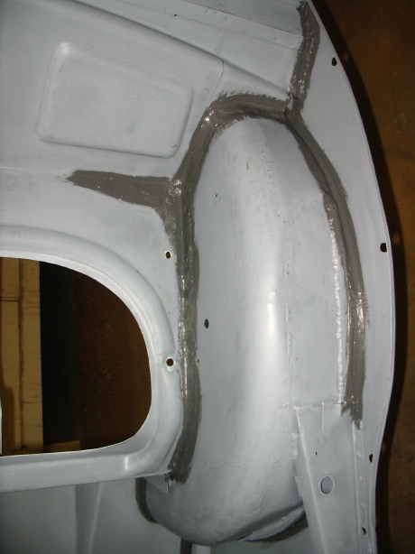
Seam sealer 5
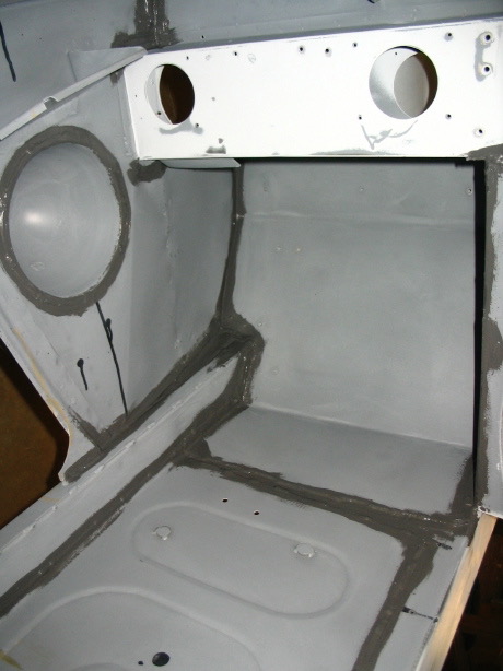
Seam sealer 8

Chip Guard for the Wheels Wells – We decided to use a chip guard product in the wheel wells and will also use the same product under the front portion of the front shroud. It turned out very well, nice even coverage. The final red paint will then be sprayed over the chip guard so that it isn’t quite so obvious. 
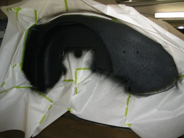
Chip Guard 1
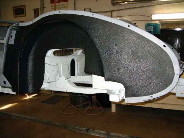
Chip Guard 3
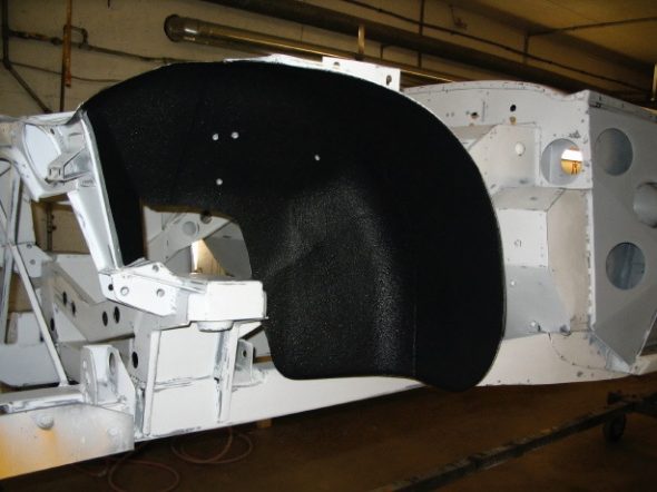
Chip Guard 4

We also drilled access holes in the frame and outriggers and applied an etch primer as well as paint to protect against rust. I will need to decide if I will plug the holes or just leave them open.

Engine Work Again – I received the rebuilt rocker arm assembly from The Rocker Arm Specialists and could not have been more pleased. The installed the new pedestal with the threads for the oil pipe and rebushed the whole mechanism. It looks great as well.
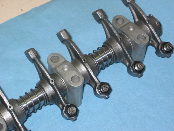
Rebuilt rocker assembly
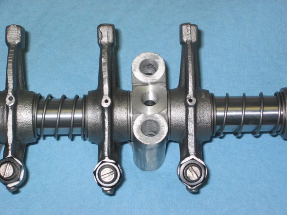
Rebuilt rocker assembly

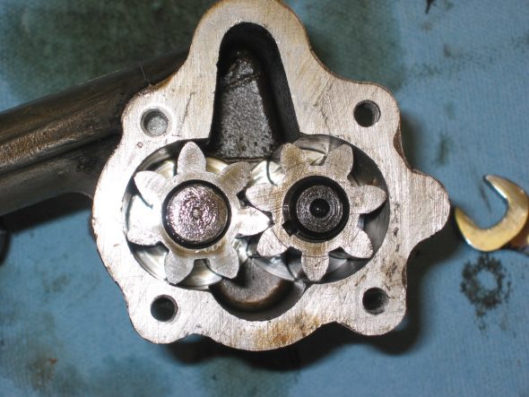
Oil Pump Removal and Inspection – After dropping the oil sump and cleaning it up a bit, I removed the oil pump to inspect it. I think I will go ahead and replace it to be on the safe side. It is the gear type pump, but others have recommended the rotary pump and since the fit is interchangeable, I think I will take their advice.
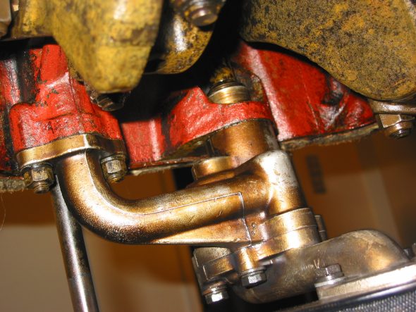
Oil Pump 5
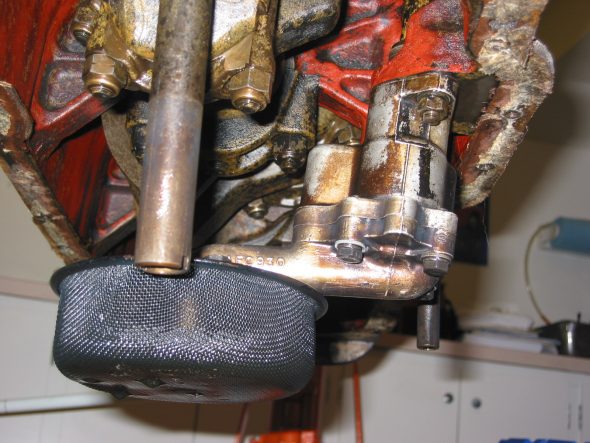
Oil Pump 2
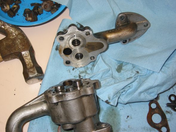
Oil Pump 8
Oil Pump 7



Chapter 29 – Cleaning and Trial Fitting

September 4, 2006

Initial Work on the Engine and Driveline

Clutch and Flywheel – Many who have used the Smitty gearbox conversion have suggested fitting a later BJ8 diaphragm clutch rather than the the spring actutated clutch originally used on the BT7. Now seemed to be the time to do it, so I ordered the clutch plate assembly from Moss. I also took the suggestions of others and sent my flywheel to Bill Bolton in exchange for a lightened (now 24 lbs.) BJ8 flywheel. The wheel that came back from Bill was pretty rusty in the non-contact surface area so a little time was spent with rust remover and the drill and wire brush. Even after cleaning, I still think I will give it to Jeremy to media blast the non-contact surfaces.

BJ8 lightened Flywheel 1

BJ8 lightened Flywheel 2

September 6, 2006

Jeremy Turner’s Work Continues

Rear shroud with filler 2

Rear shroud primed 1

Rear shroud primed 2

rear shroud final primer

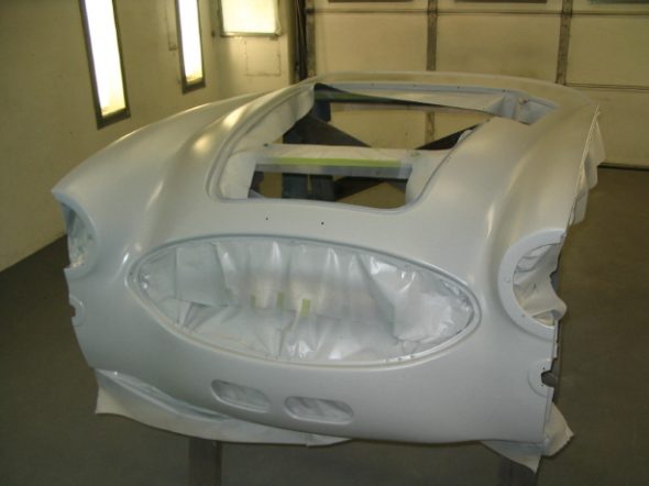
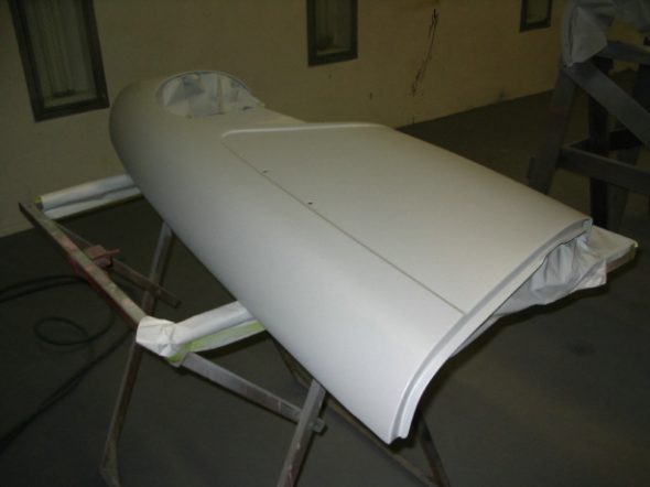
Shrouds – Jeremy is working on the “Bloody Beast” with the idea of completing all the priming and final panel fitting withn two weeks. He is focused on my car completely. He has just completed the body filler and priming for the front and rear shrouds.

Front shroud bodywork 2

front shroud poly primed

Front wing final primer

right front wing final primer

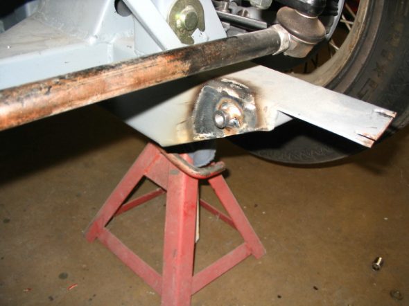
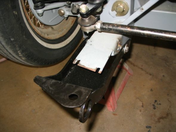
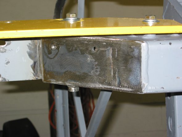
Because Martin Jansen did not put the bumper bracket mounting tubes all the way through the frame, Jeremy needed to weld some short tubing into the inside of the frame rails to mount the Cape International driving light/tow hook.

tow hook mount

tow hook mount 2

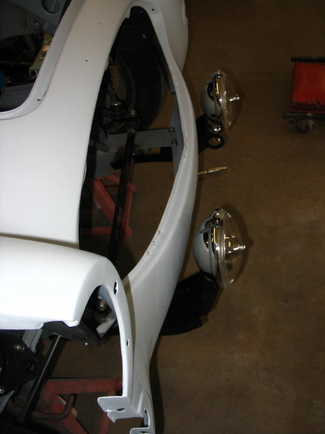
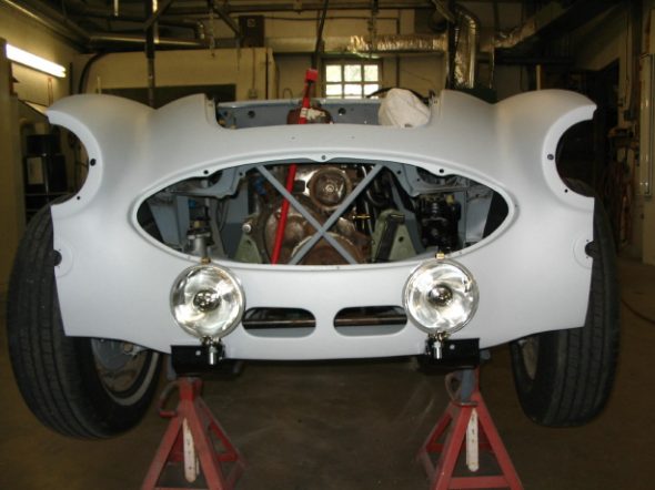
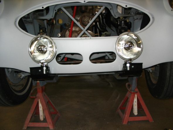
And now, don’t those Lucas drving lights look nice!

Fitting driving lights 2

Fitting driving lights 1

Fitting driving lights 3

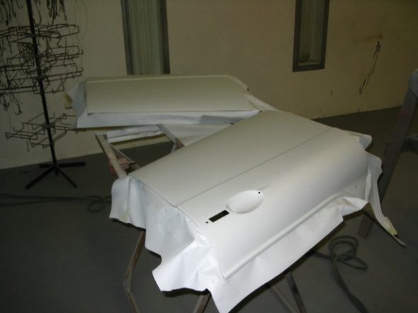
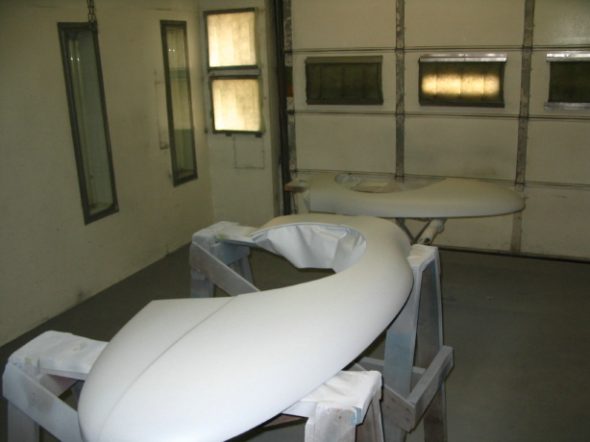
Final priming on doors and rear wings.

Doors final priming

Rear wings final priming

September 11, 2006

Jeremy Turner’s Work Continues

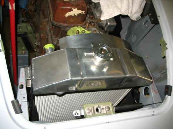
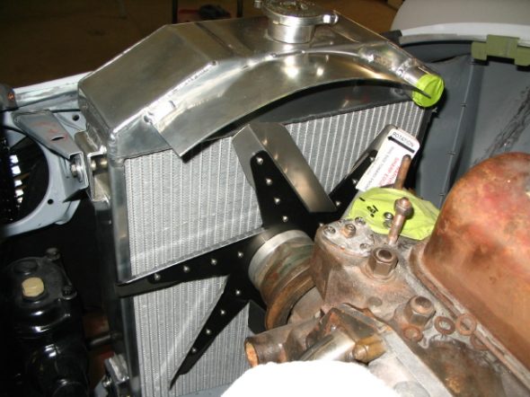
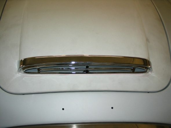
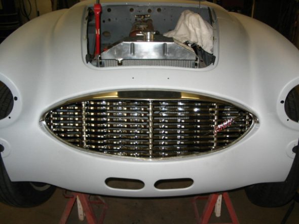
Before going any further, it was a good idea to check the fit of the radiator, fan and the body and bonnet grilles to ensure a good fit. The radiator cap did hit the bonnet so some more work was required to adjust the radiator and shroud. We ended up with about 1/8” clearance between the radiator cap and the bonnet. The bottom trim piece on the body grille wold not fit properly so it was decided to have the original rechromed.

Radiator installed

Fan installed

Bonnet grill installed

Shroud with grille