Rostra Cruise Control
Components
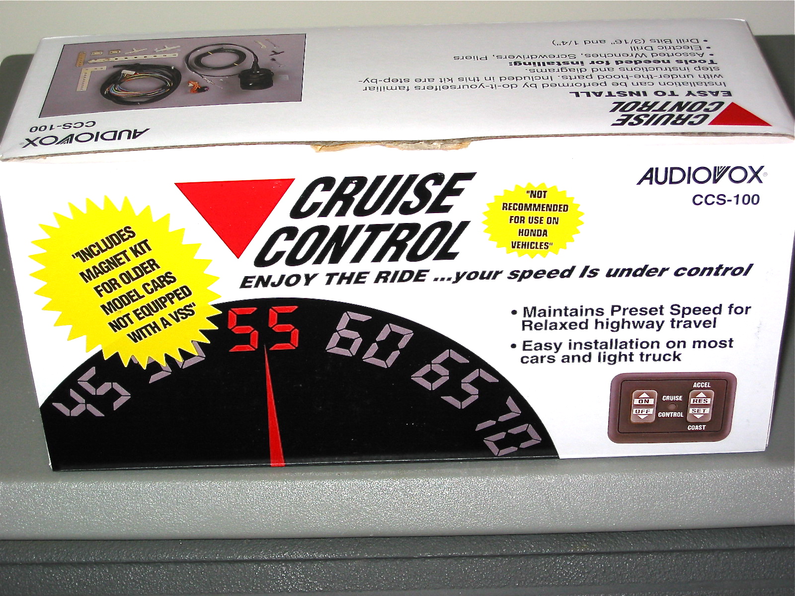
I installed an Audiovox CCS-100 Cruise Control system on my Healey and found it to be a useful modification. I am over six feet tall and the seating position in British cars can be uncomfortable on long drives. The cruise control makes those trips a bit more relaxing and enjoyable.
Rostra Precision Controls, Inc. manufacturers the cruise control system I am using in the Jaguar MK2. Many of the same components of Rostra’s system have evolved from the earlier version marketed by Audiovox. The earlier iteration worked on a vacuum servo while the current version by Rostra uses all electronic components. Rostra also manufactures a number of other automotive electronic devices such as Bluetooth systems, rear cameras and etc. The company is located in North Carolina and this is their website: http://www.rostra.com. Rostra does not sell directly, but they have many other vendors selling their products such as Summit Racing and many others.
There are a number of components in the cruise control system. These include:
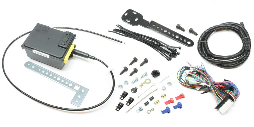
Part #250-1223: The Global Cruise Module Assembly includes the universal Global Cruise servo motor, throttle cable, universal mounting brackets, wiring harness and hardware package for making electrical and throttle control connections. The servo motor mounts in the vehicle’s engine bay.
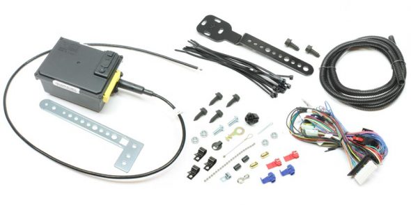
Rostra 250-1223 Servo
These are the directions provided with the Global Cruise Module:rostra-global-cruise-250-1223-instruction-manual
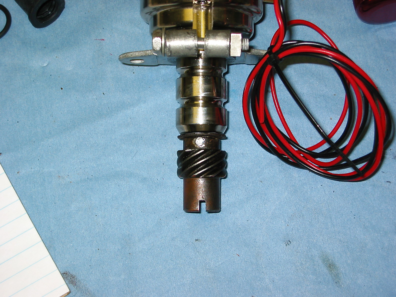
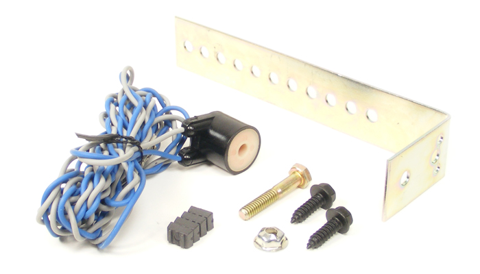
Part #250-4165: includes the speed signal generator with sensor, magnet and strap.
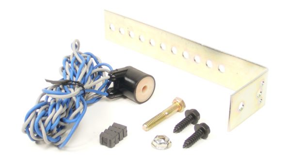
Universal Magnet Speed Signal Generator
Cars more modern than the 64 Jaguar equipped with electronic speed signal (VSS) capability don’t require a magnetic sensor, but in the analog world of the MK2, a magnet is secured to the propshaft and the sensor is located in close proximity to measure revolutions or pulses per mile. These are the directions provided with the Universal Magnet Speed Signal Generator kit: rostra-installation-of-the-road-speed-sensormagnets-pick-up-coil
Part #250-4382: is a pre-wired five pin relay to compensate for the use of LED brake lighting.
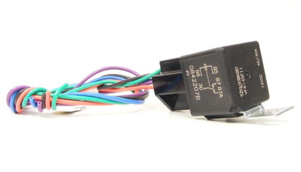
Relay Package
While the included primary wiring harness of the Global Cruise system includes wire leads meant to be attached to both the ‘hot’ and ‘cold’ sides of the brake pedal sensor to disengage the cruise control when the brake pedal is depressed, the proper ground signal is no longer present when a vehicle has been outfitted with LED lighting accessories such as LED brake lights. In a case like this, a 5-prong automotive relay must be used to provide the ground signal to cancel the cruise control once engaged. A MK2 owner using original incandescent light bulbs wouldn’t need this relay, but I have converted my lights to LEDs so this addition is required. These are the directions provided with the pre-wired 5 pin relay: rostra-250-4382-5-wire-relay-wiring-diagram
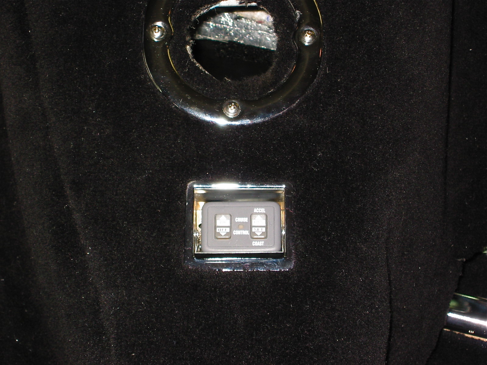
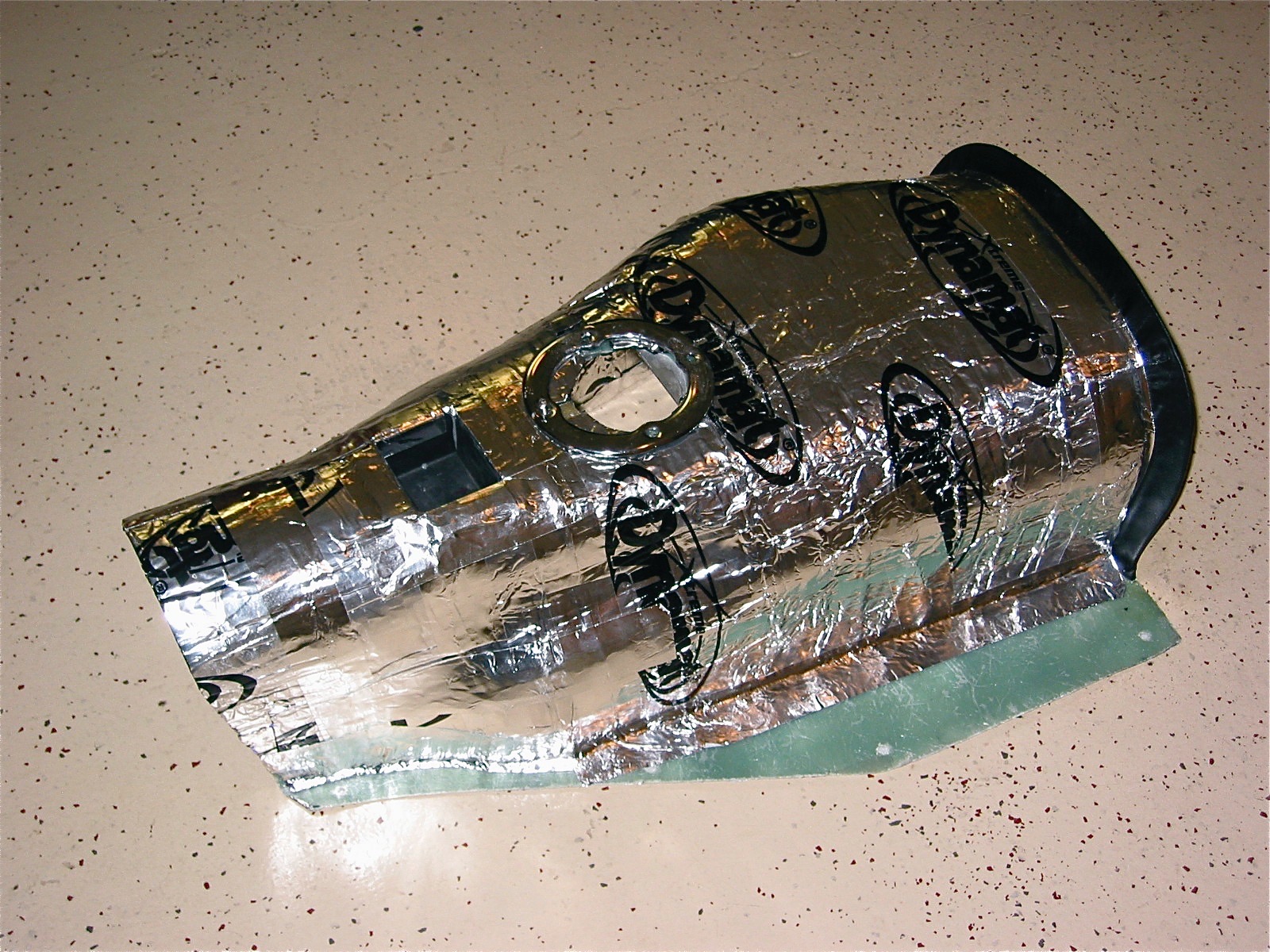
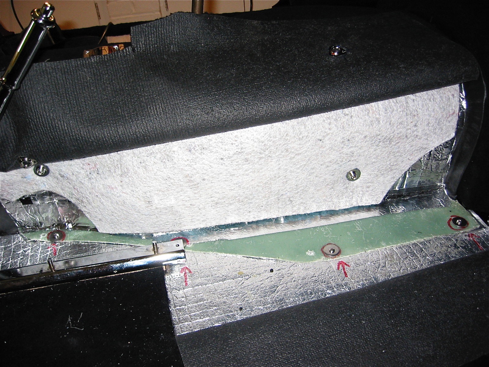
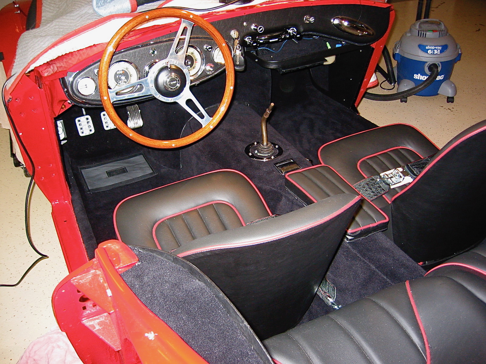
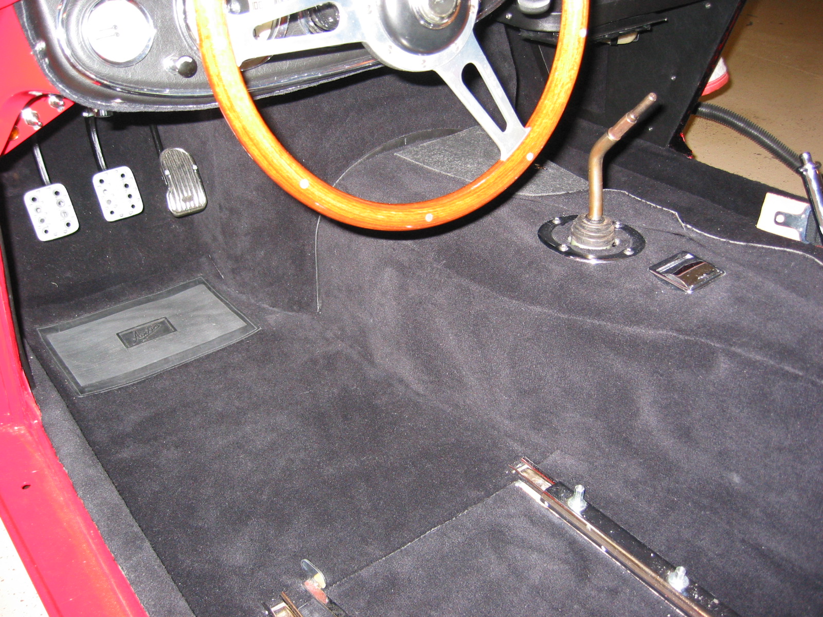
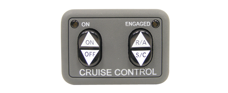
Part #250-3592: is the dash mounted control switch that includes a small LED light that illuminates when the cruise is engaged. An otherwise identical control switch, but without the engagement light is also available and is part #250-3593. I am using #3592 that also requires an additional 5 pin relay. I am not mounting the switch on the dash, as I am “hiding” my switch in the modified center console where the ash tray was originally located.
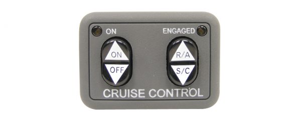
Universal Dash Mount Switch
These are the directions provided with the control switch: rostra-dashmount-installation-instruction
Installation
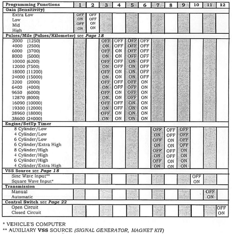
Step one for me was to set the electronic switches in the global cruise module. There are a total of twelve switches with “On/Off” settings. Rostra encourages beginning the installation with the factory settings and then modifying the settings based on individual applications.
rostra global cruise control module settings
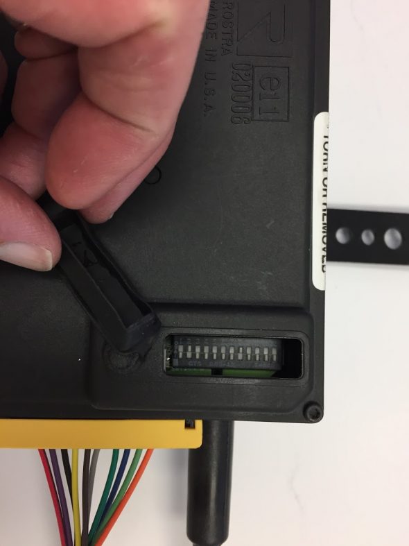
Global Cruise Switches
The twelve switches configure the control module for the type of car in which the system is being installed.
Switches #1 and #2 are for sensitivity or gain. Rostra’s directions state the following: Gain is how the cruise reacts to road conditions and motor size. Always start at Mid gain. If vehicle surges, change gain. For a fast surge, switch to a low or extra low gain setting if needed to tune the cruise. If there is a slow surge, switch to high gain. Therefore, I will initially set switch #1 to “OFF” and switch #2 to “ON.”
Switches#3 through #6 are for the pulses for minute. I assume (always dangerous) that the MK2 will probably have about 3,000 to 3,500 rpms at 60 mph therefore, I will initially set switch #3 to “ON,” switch #4 to “OFF,” switch #5 to “OFF,” and switch #6 to “OFF.”
Switches #7 through #9 are for the engine set-up (cylinders). Rostra’s directions state the following: Engine/Setup timer is how fast the cruise retracts the cable at onset. Always start at low. If vehicle drops below set speed but then recovers, switch to a high or extra high if set speed is not acceptable. Of course the Jaguar MK2 3.8 is a 6 cylinder engine therefore, I will initially set switch #7 to “OFF,” switch #8 to “ON,” and switch #9 to “OFF.”
Switch #10 is for the input source – Sine Wave or Square Wave. The Jaguar MK2 must use the magnet kit as the pulse indicator and as the chart above indicates, switch #10 is set to the Sine Wave Input or “OFF.”
Switch #11 is for the transmission type – manual or automatic. I have a manual gearbox in my MK2 therefore, I will set switch #11 to “OFF.”
Switch #12 is for the type of control switch. Rostra’s directions state the following: Your control switch is an Open Circuit Control Switch if: Its Rostra part number is 250-3592 (among others). I am using the dash panel control switch #250-3592, therefore in keeping with the table above switch #12 is set to “OFF.”
In summary:
#1 OFF
#2 ON
#3 ON
#4 OFF
#5 OFF
#6 OFF
#7 OFF
#8 ON
#9 OFF
#10 OFF
#11 OFF
#12 OFF
Global Cruise Module Mounting
The Rostra instructions indicate that the Module should NOT be mounted in the following areas
* Under the fender.
* Under the vehicle.
* Directly to the engine.
* With the cable pointed down.
* Near sharp, hot or moving objects.
* Near ignition coil [No closer than 10″]
* In the passenger compartment (Noise).
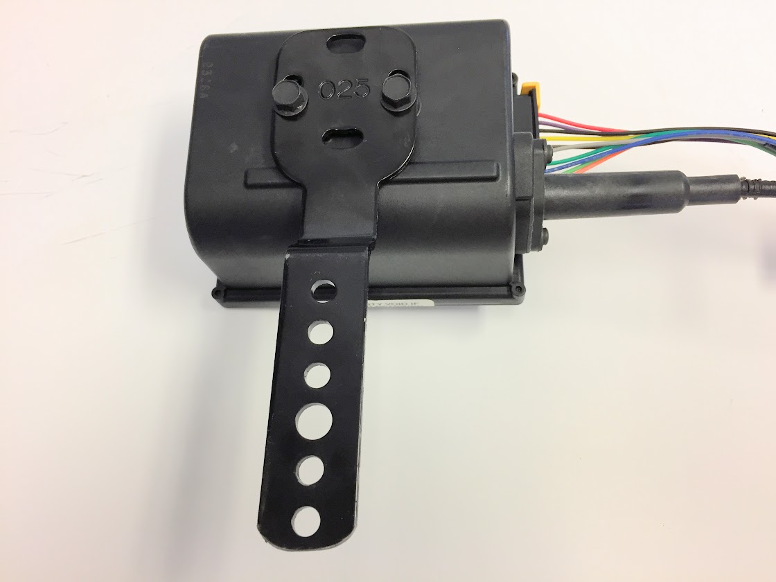
The module needs to be mounted in a location that will provide sufficient “reach” for the module’s throttle control cable to link to the carburetor throttle linkage. A fairly heavy duty bracket is provided to mount the module to the car and it can be mounted in one of two orientations:
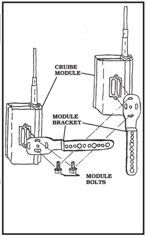
Cruise Control Module and Mounting Bracket
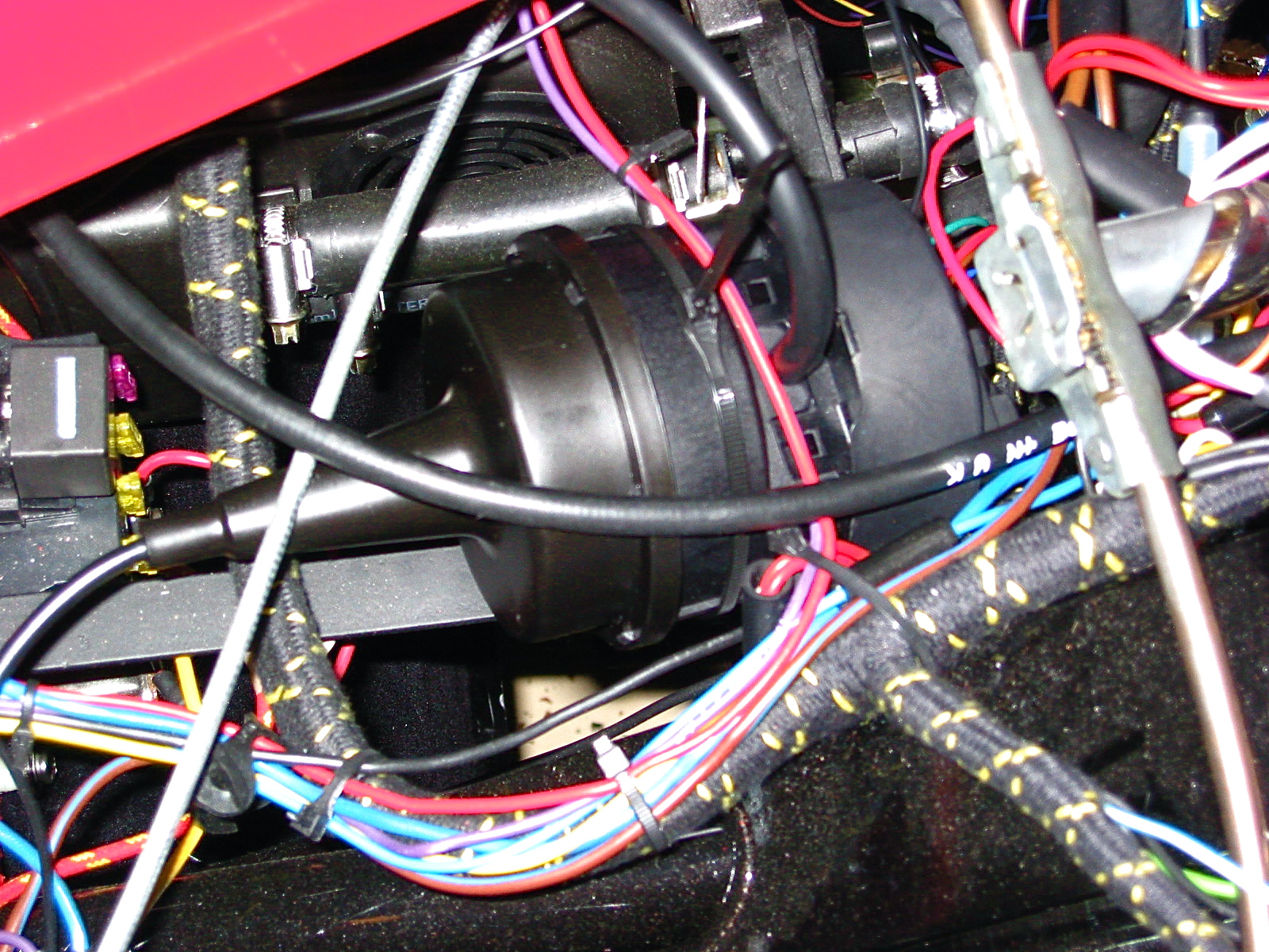
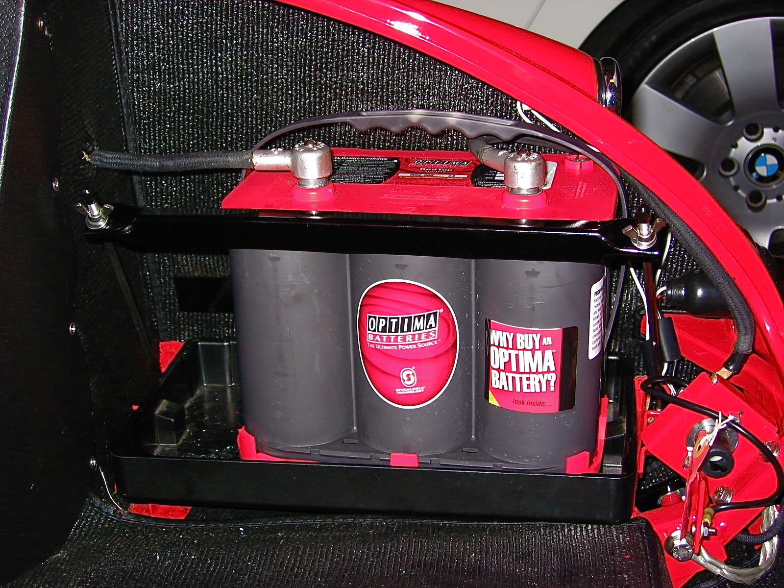
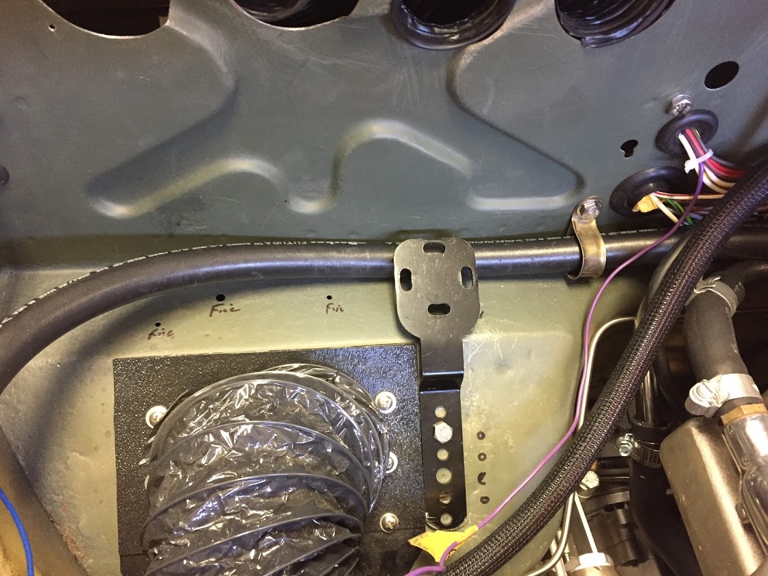
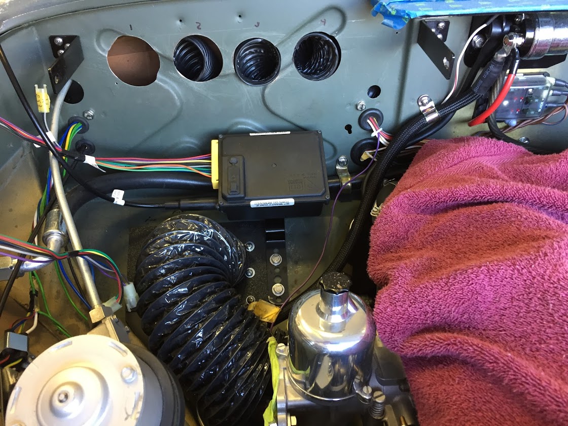
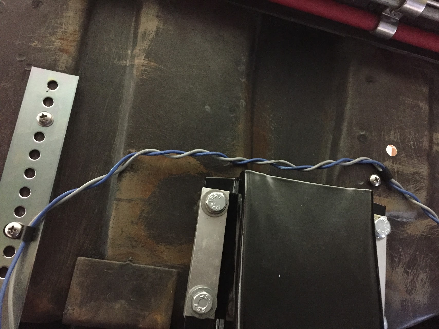
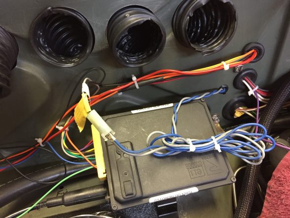
My battery is relocated to the boot to accommodate the placement of the air conditioner evaporator on the RH firewall. I had enough clearance to mount the module under the evaporator. This location permitted me to hide the module as best I could.
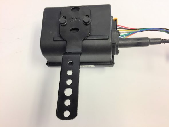
Global Cruise Module with Mounting Bracket

Mounting Bracket

Global Cruise Module Installed
Global Cruise Module Wiring
Because the Rostra kit is for universal applications, the wire runs in some cases are quite long and I decided to shorten a number of them which then effected some of the connectors that were used. There are also situations in which not all of the wiring provided is used.
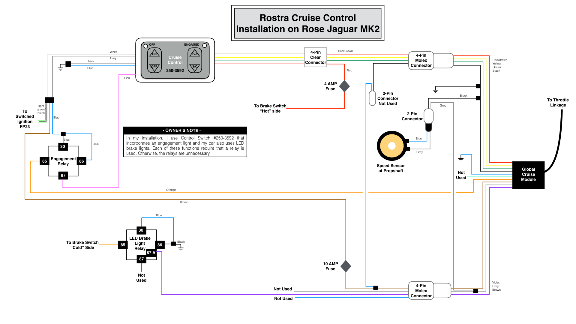
My wiring diagram, tailored for my 1964 Jaguar MK2 application, is provided below. As the disclaimer at the top of this post indicates, the wiring description in this post journals what I did for my car. It is not my intention to describe what you should do for your car!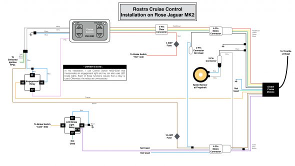
This is a link to the same wiring diagram as a pdf file rather than as a jpeg file.rostra-cruise-control-wiring-for-jag-mk2
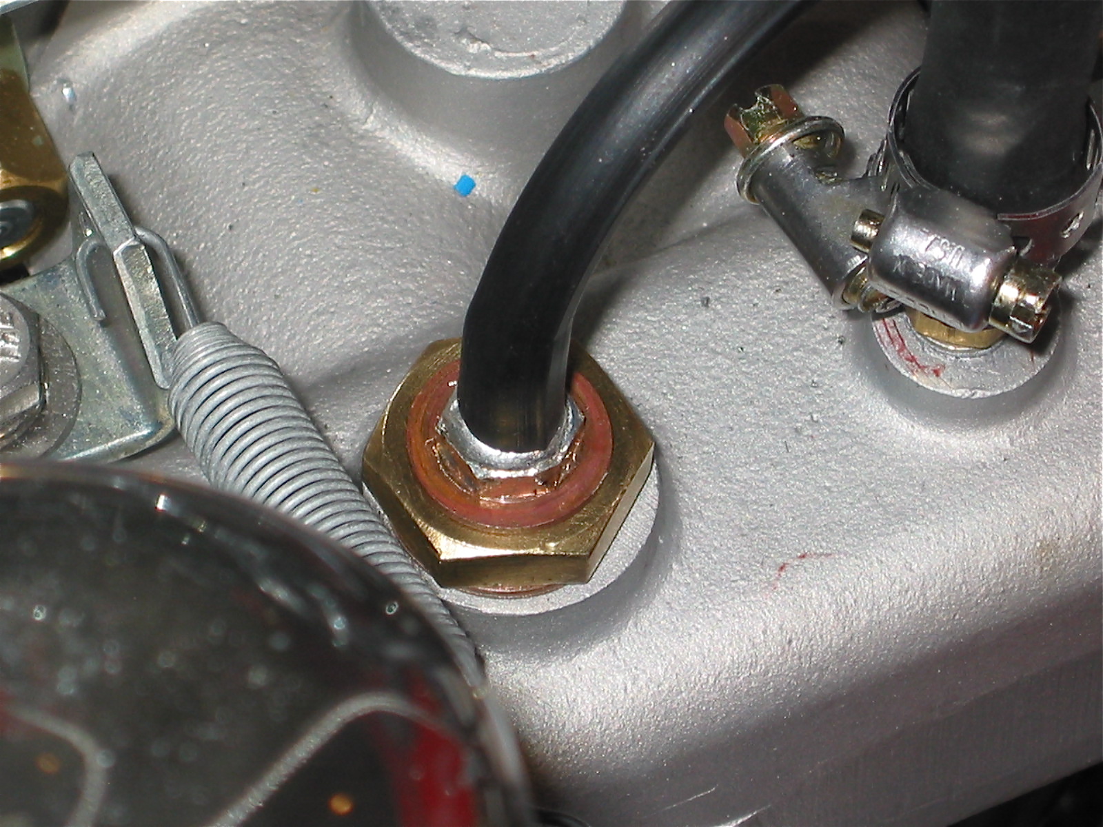
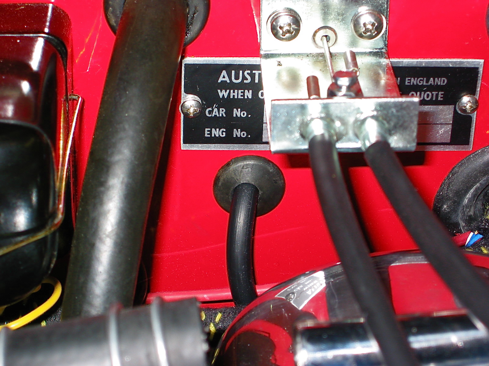
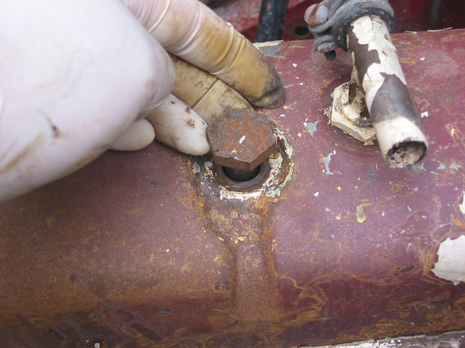
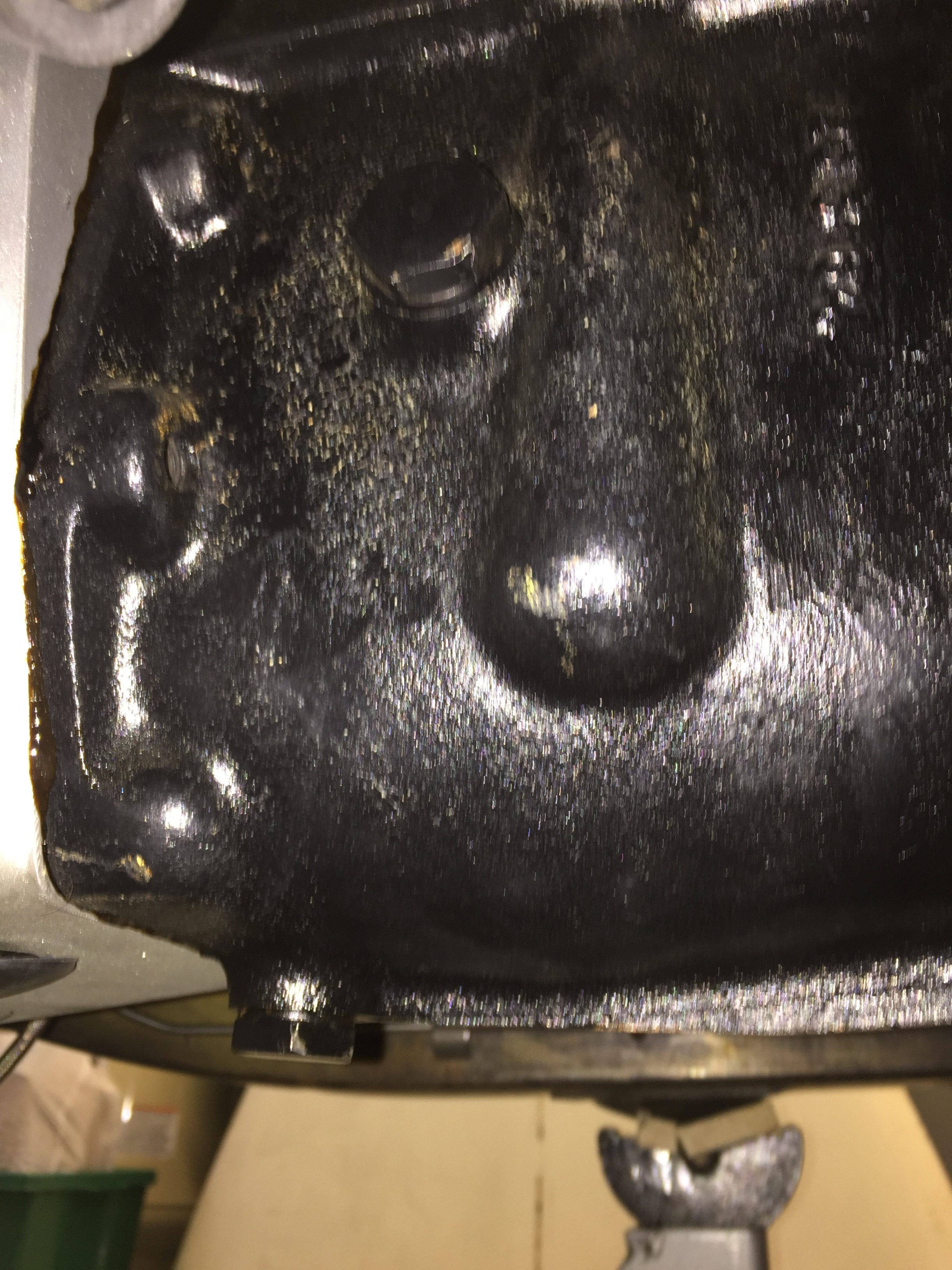
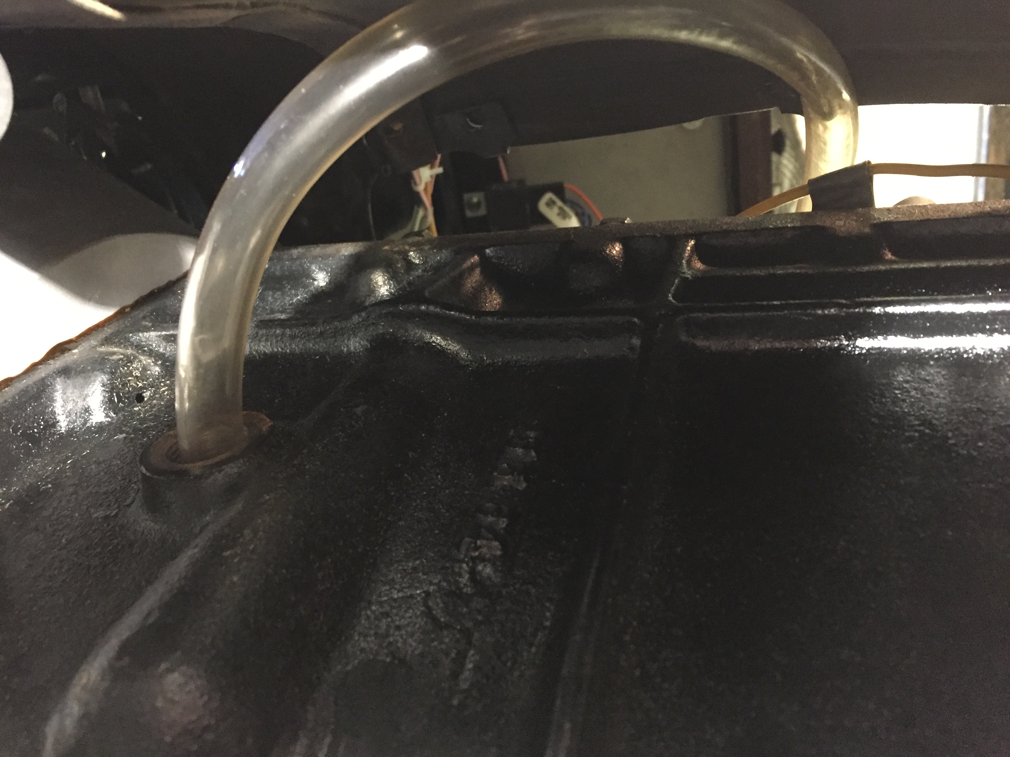
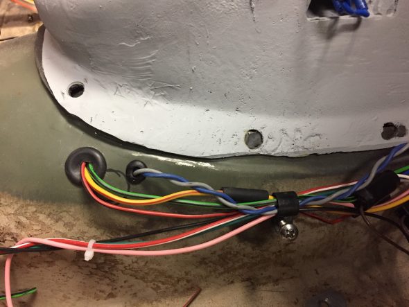
The Rostra instructions for the Global Cruise Control Module indicate that the wiring emanating from the module needs to pass through a 3/4″ hole in the firewall. I already have an unused firewall port as seen in the image above, so I will use it for the wiring. I slid a firewall rubber grommet over the wiring harness to help seal the opening. The control module has a total of ten (10) wires, although the black and grey wires are spliced to create three black wires and two grey wires for a total of twelve (13) wires. The wires are “bundled” for routing through the firewall.
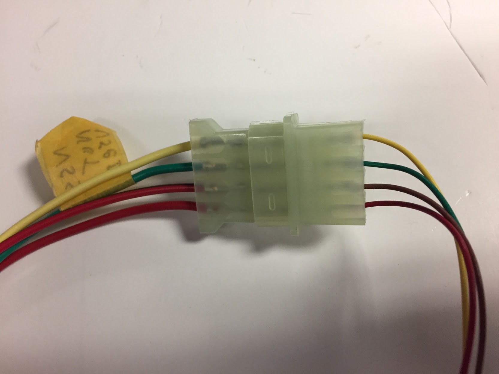
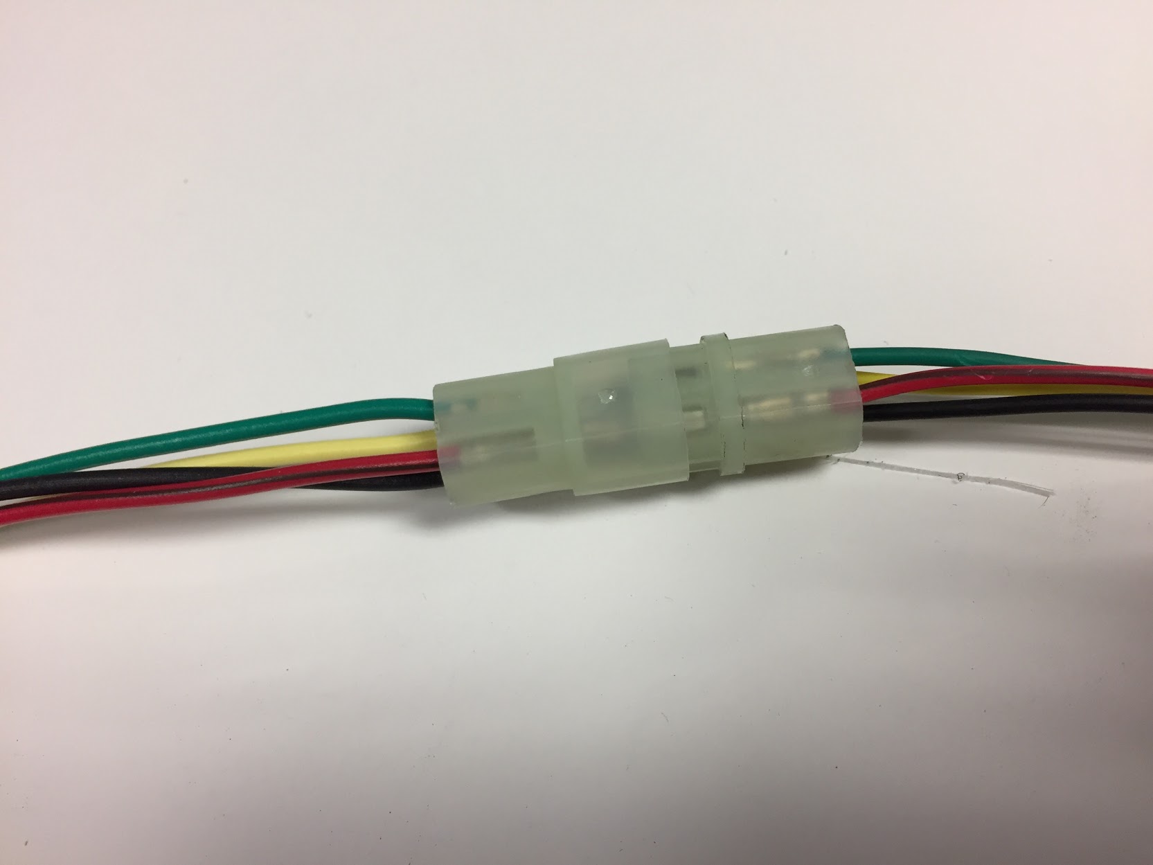
Bundle One: red/brown, yellow, black and green wires from the control module to a clear plastic female four pin connector. This connector is mated with a male four pin connector with four wires of the same colors. The red/brown, yellow and green wires are then routed to a male clear plastic flat four pin connector.
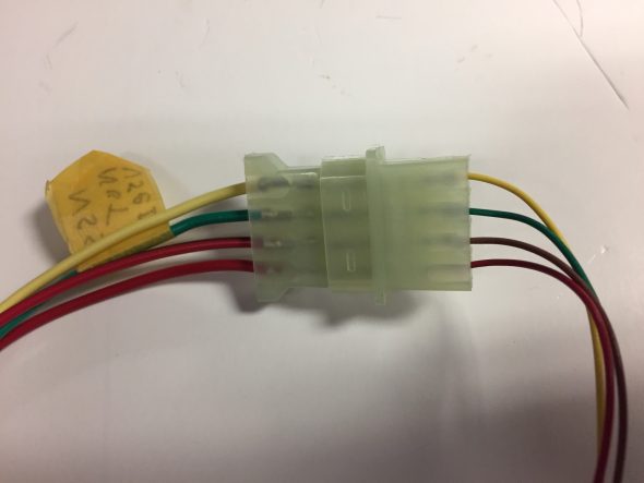
Flat Four Pin Connector from Global Control Module to Panel Switch
The black wire is routed to a male clear plastic two pin connector joining with a blue wire. These wires are not used in the system for the Jaguar. The black and blue wires are factory labeled as “to control switch six pin only.”
Red/Brown Wire – This wire is routed to a male clear plastic flat four pin connectorThis wire is routed to the “hot” side (constant 12+ volts) of the brake switch.
Bundle One Cruise Control Wires
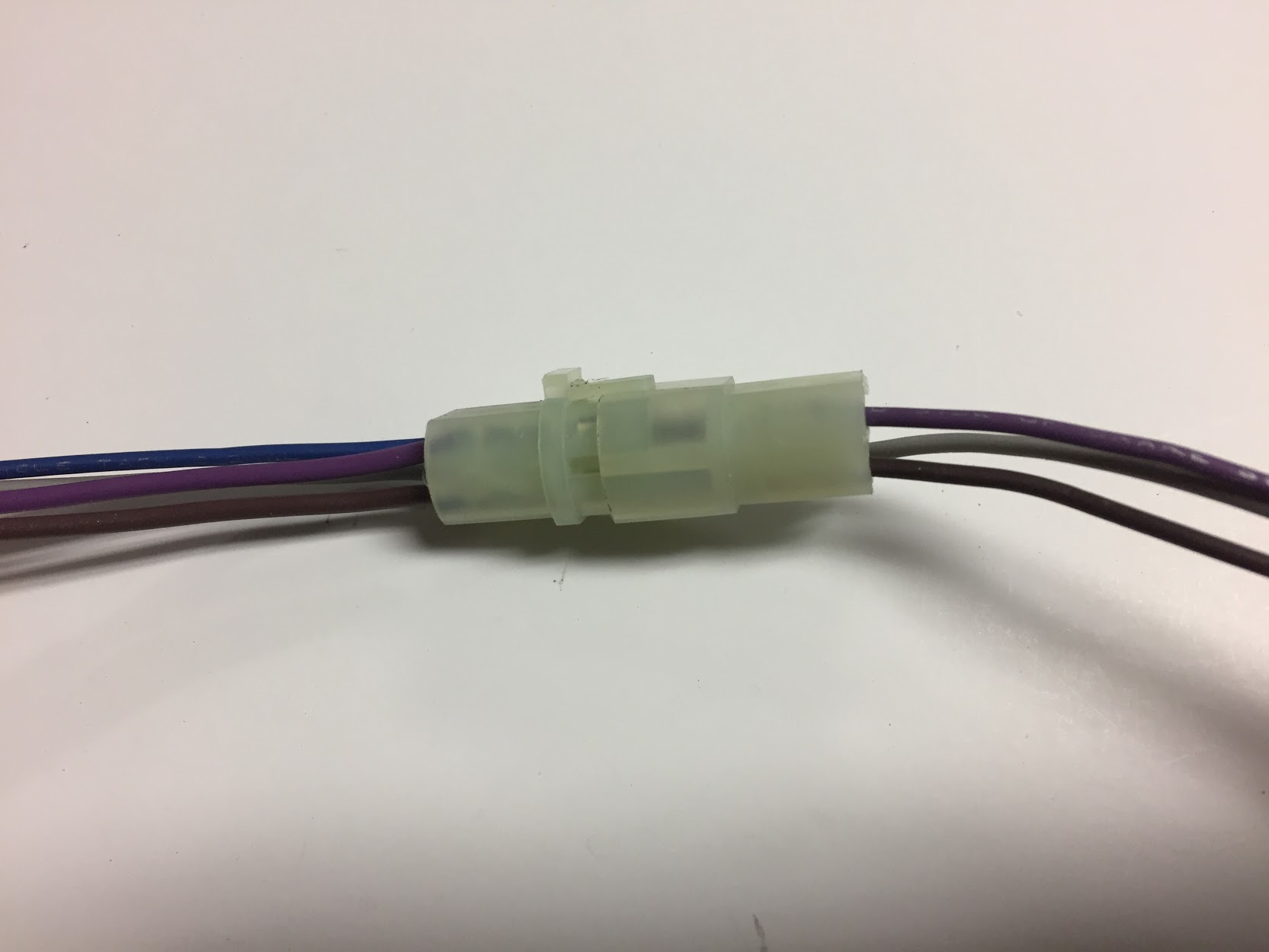
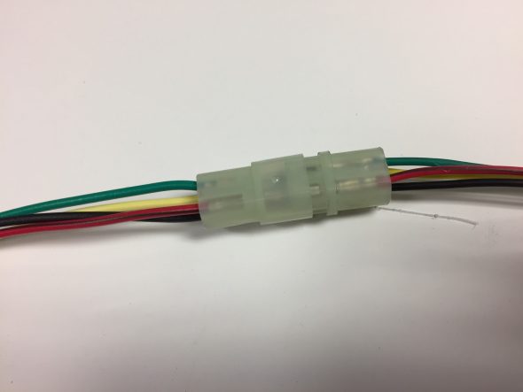
Bundle Two: violet, grey, and brown wires from the control module to a clear plastic female four pin connector.
Bundle Two Cruise Control Wires
Violet Wire – This wire is routed to the “cold” side of the brake switch (0 resistance when brake is not pressed, and 12+ volts or open resistance when the brake is pressed.
Black Wire – This wire is spliced to create two (2) black wires. One of the black wires is joined with a grey wire in a clear female plastic connector with a label entitled “optional signal generator.” The other black wire has a ring terminal connector on it and is attached to a ground connection on the chassis.
Yellow Wire – This wire joins with the
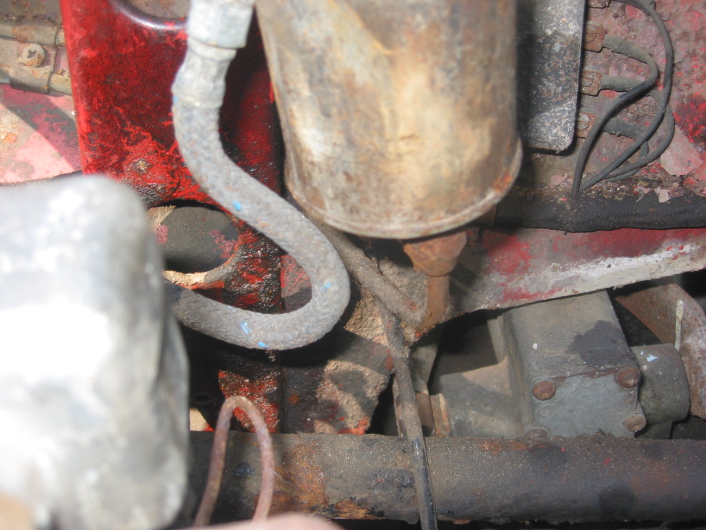
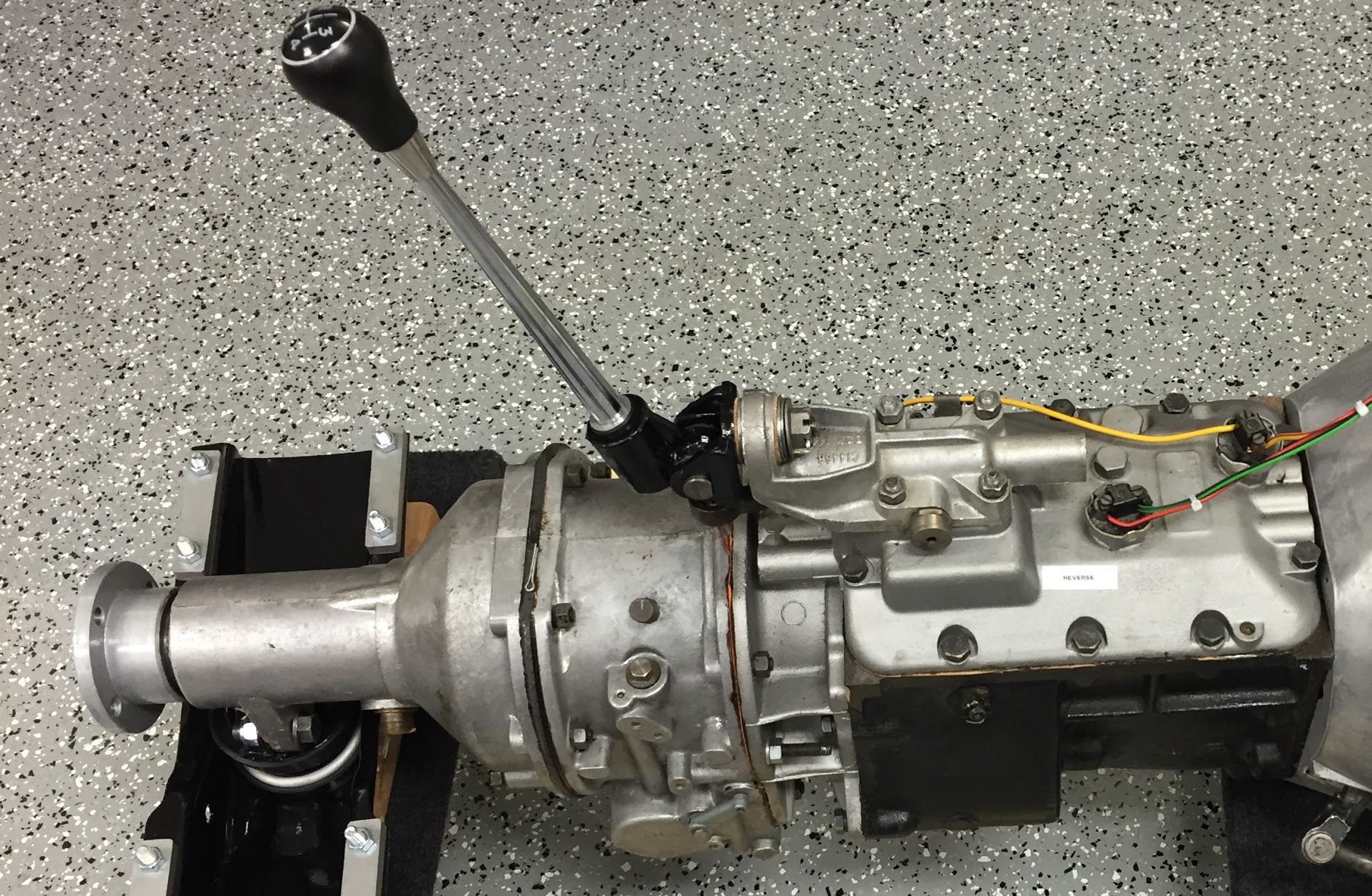
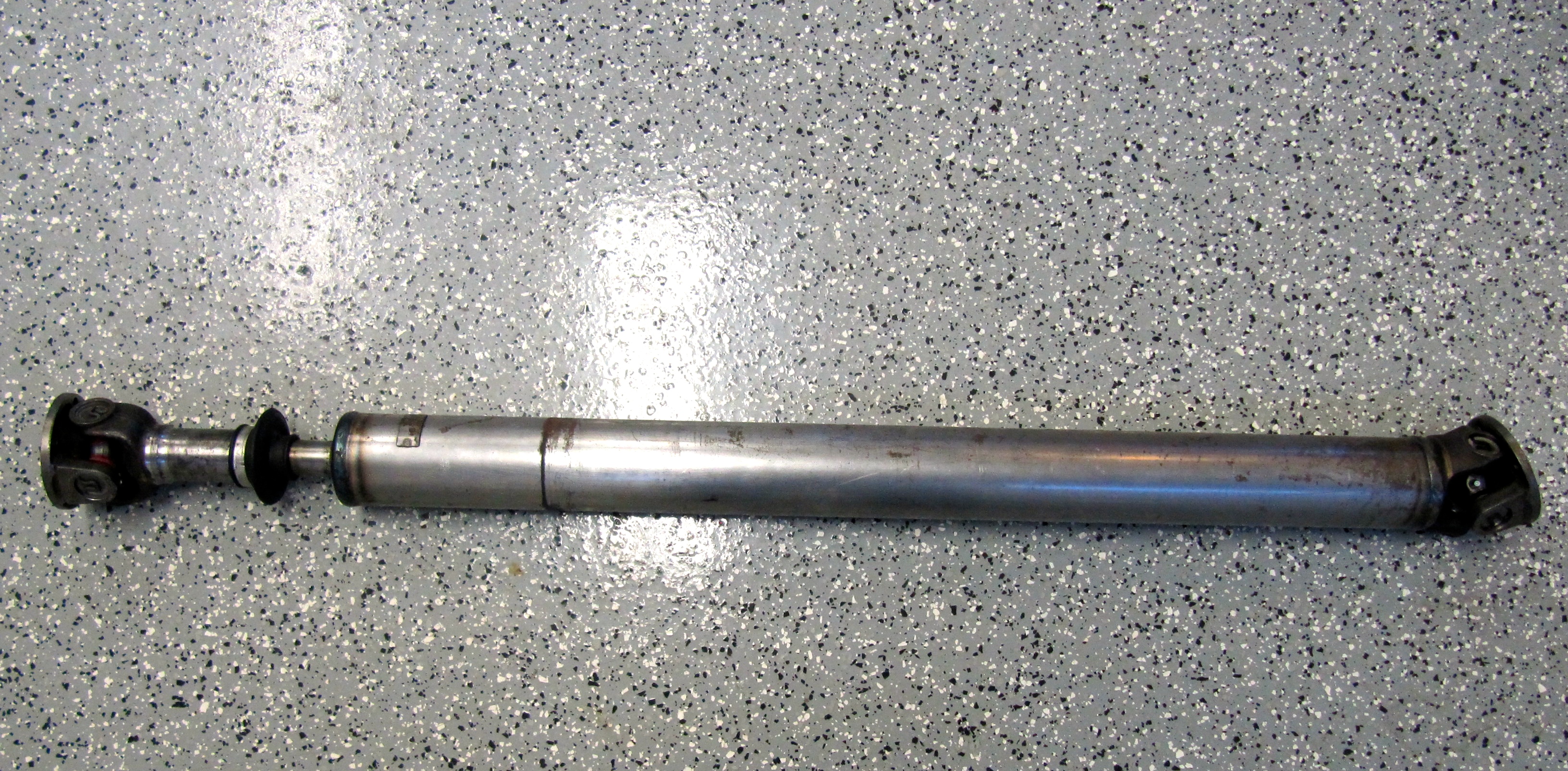
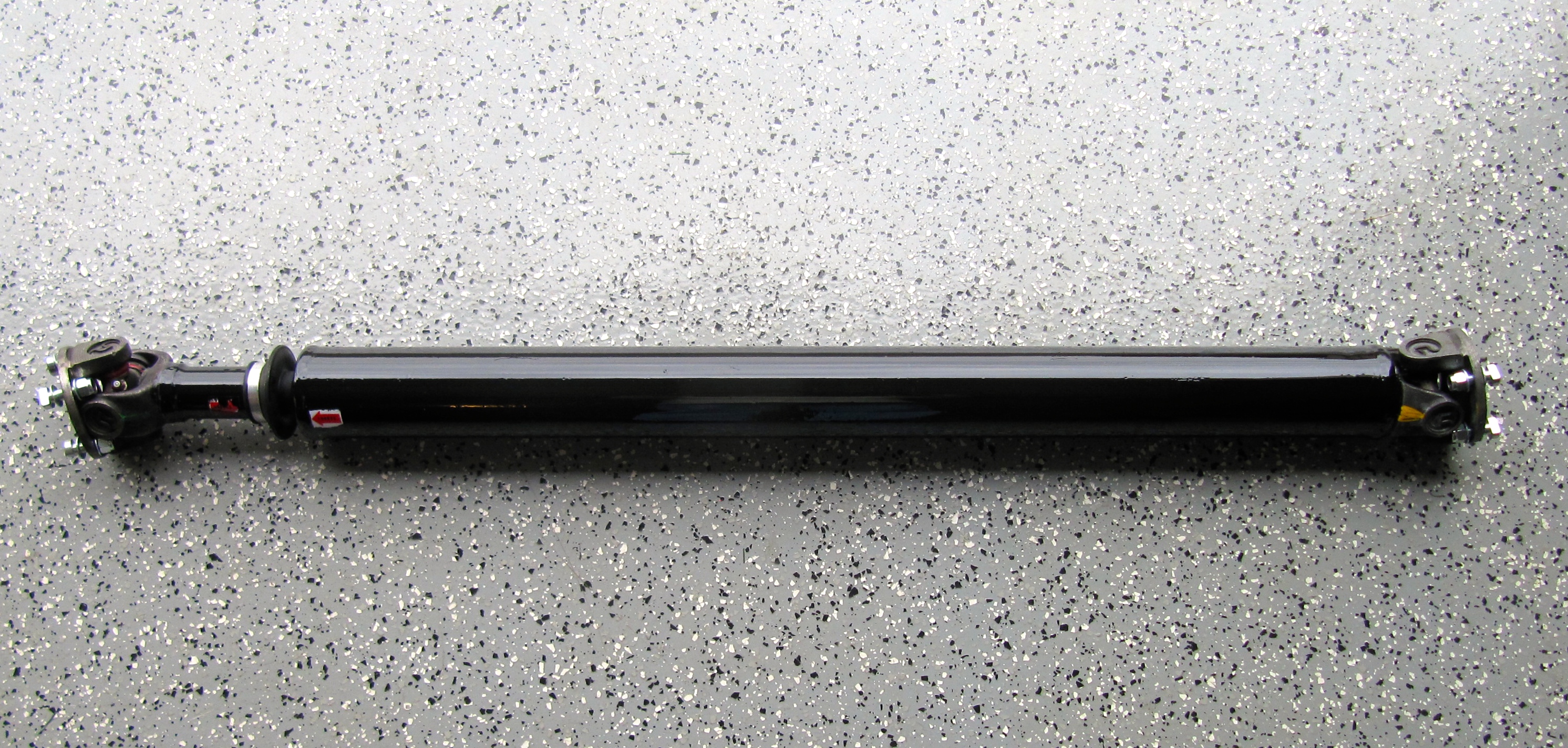
Road Speed Sensor/Magnets and Pick-up Coil Installation
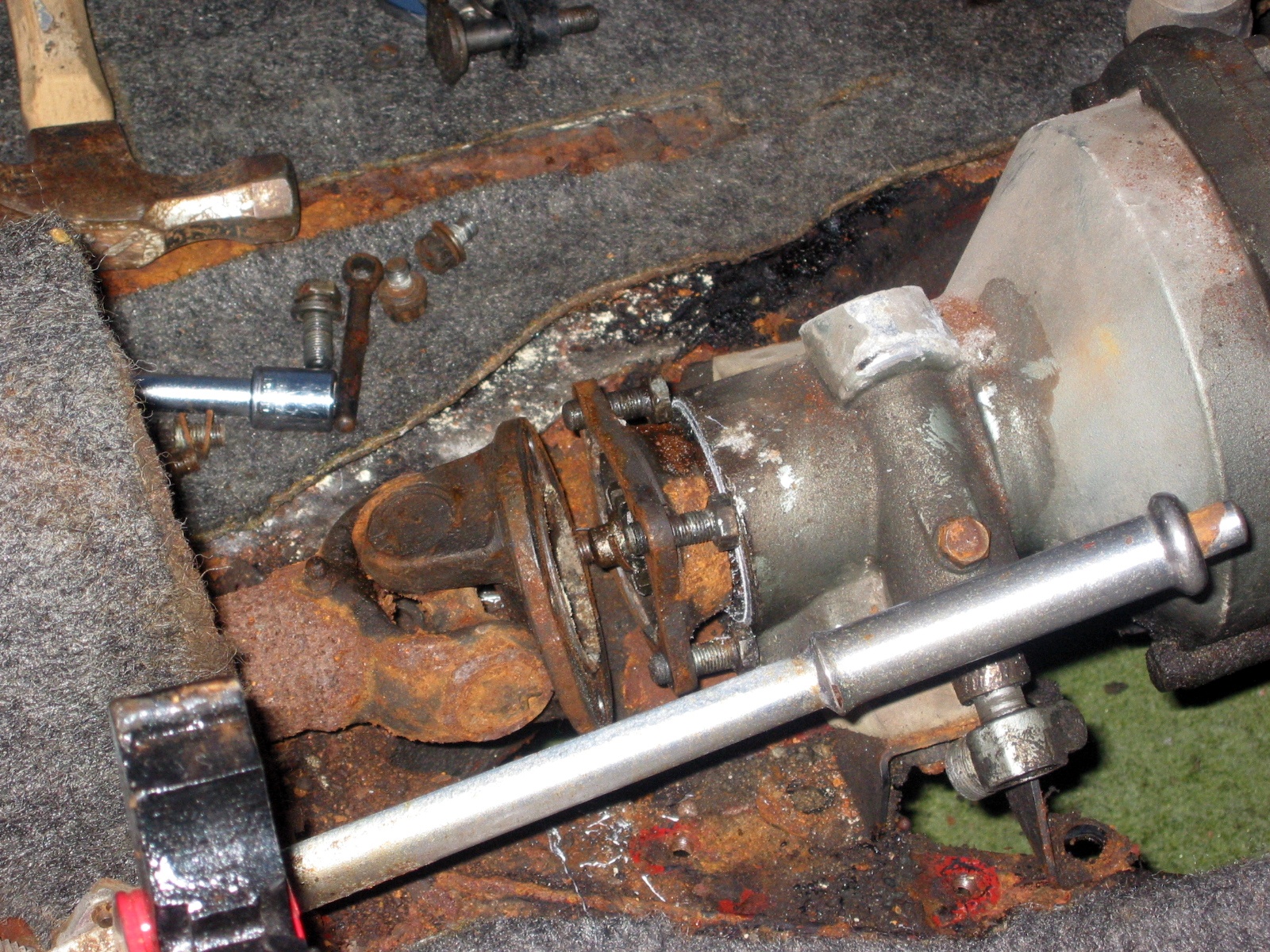
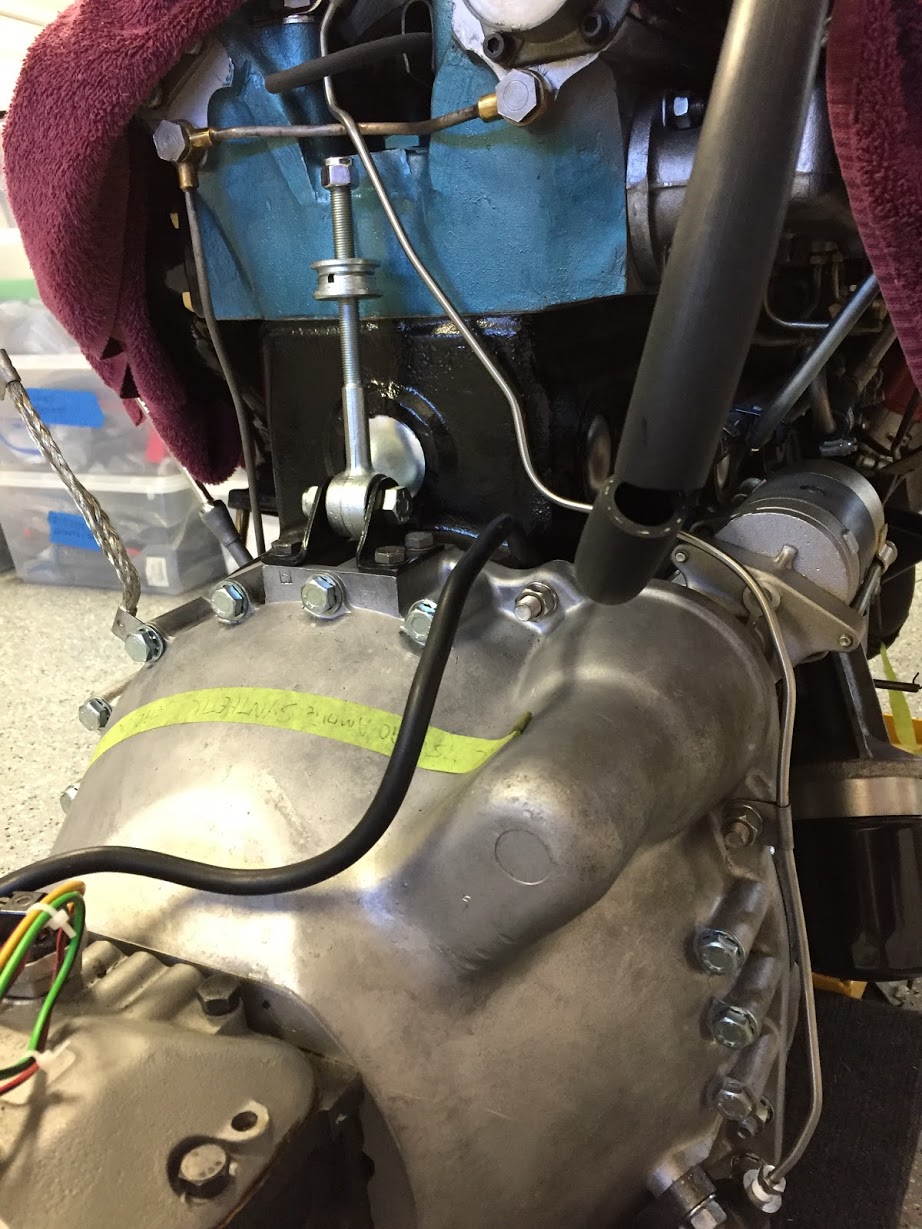
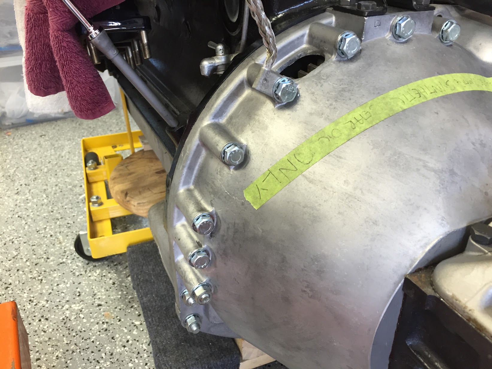
The Rostra instructions indicate that for rear wheel drive vehicles measuring distance traveled in miles per hour, one magnet should be used. Once I had the rear suspension in the car with the propshaft in the “normal” position I was able to install the speed sensor.
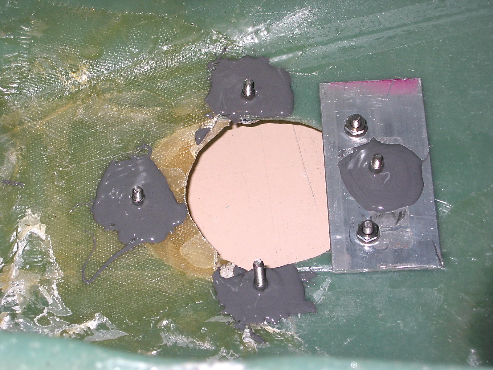
First, I bolted the road speed pick up coil to the thinner bracket supplied in the kit using the 1/4″-20 x 1 1/2″ bolt and the stamped nut being careful to not over tighten the nut as too much torque will damage the coil.
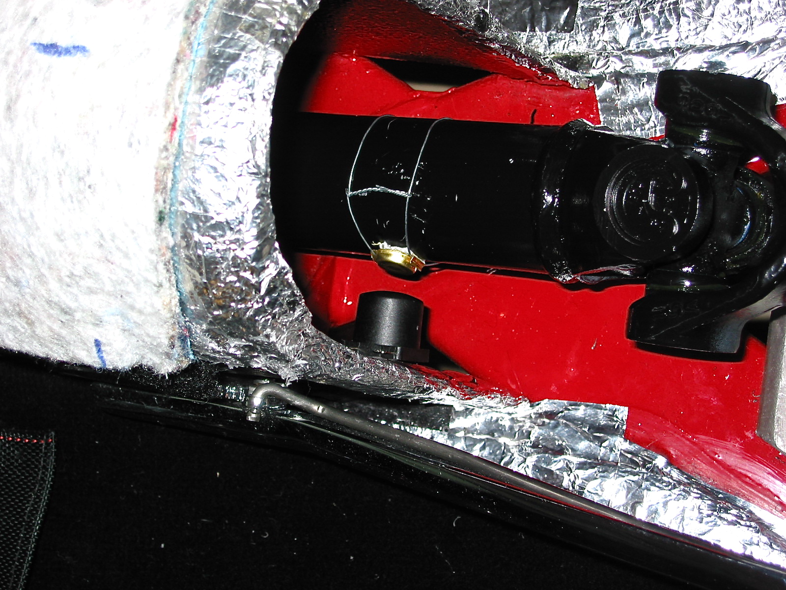
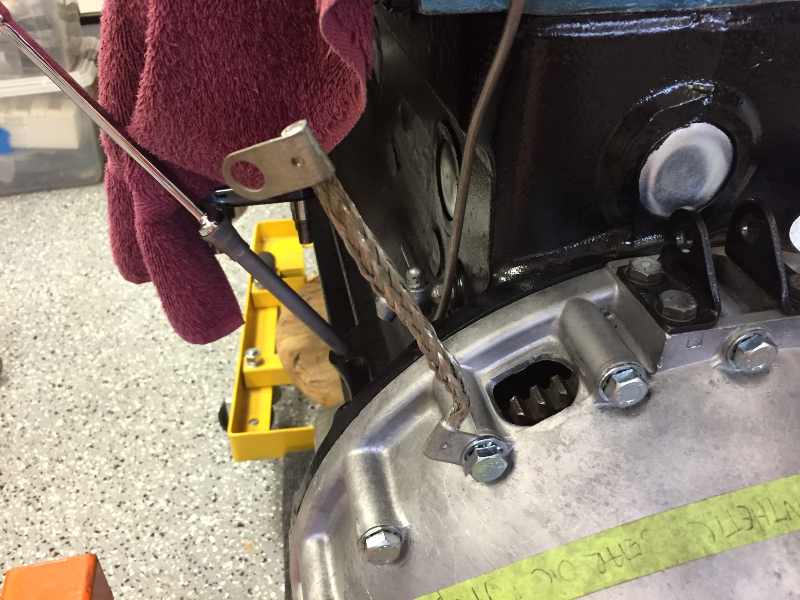
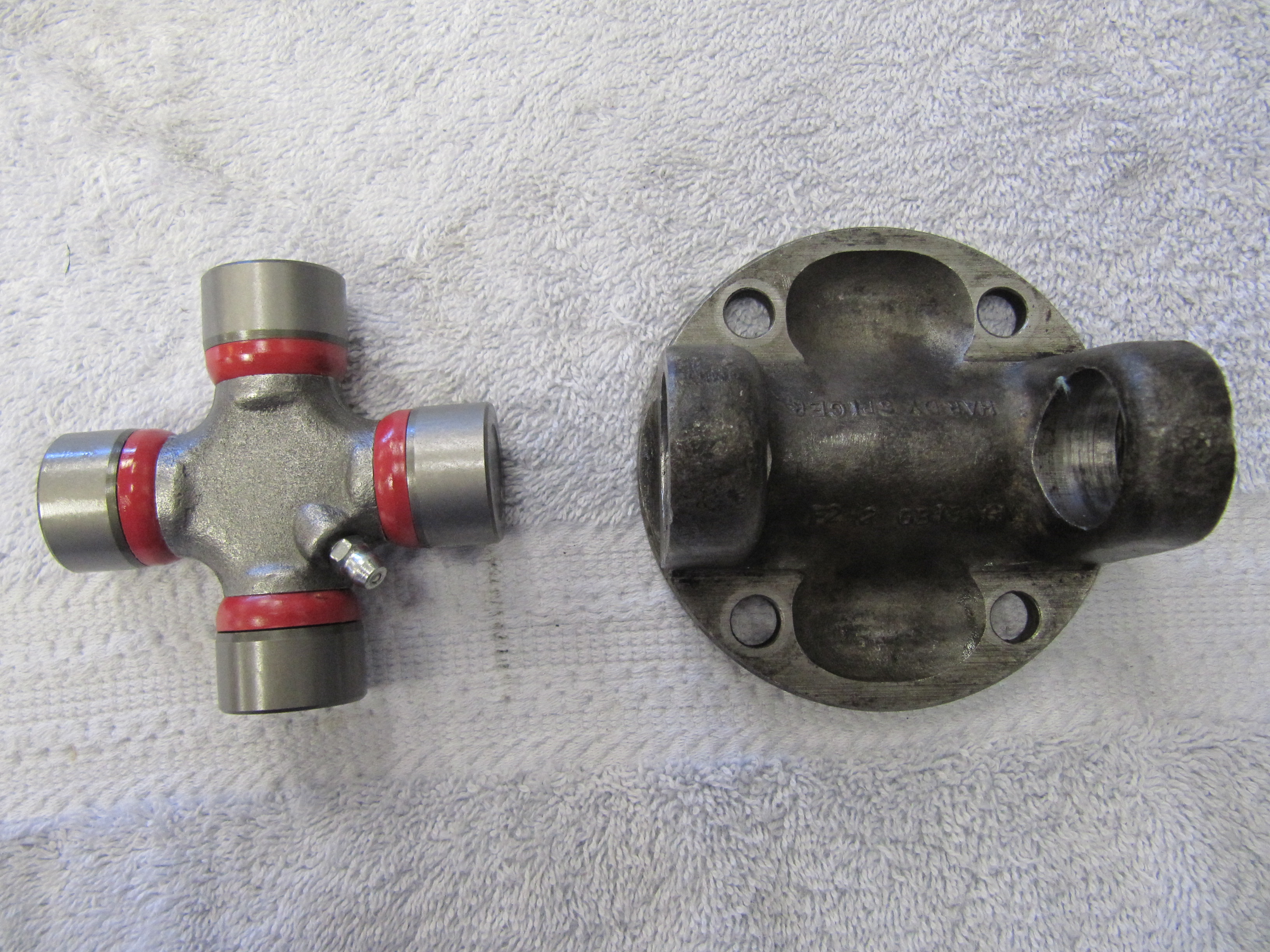
Second, I positioned the bracket under the car so that the coil bolt head was 3/4″ plus or minus 1/4″ from the propshaft and no more that 12″ in back of the U-joint. The pick-up coil was positioned in the middle of the propshaft and mounting holes were marked on the floor underside. I then installed two nutserts in the floor and mounted the bracket with two #10 -24 x 1/2″ machine screws.
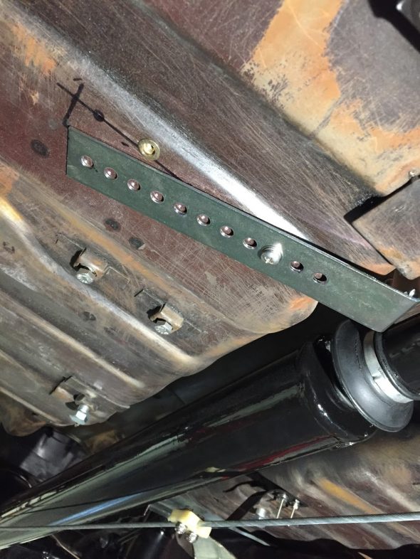
Positioning the pick-up coil and bracket
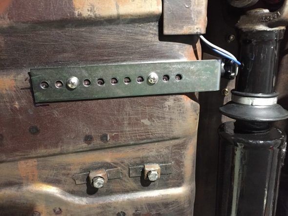
Pick-up coil and bracket mounted
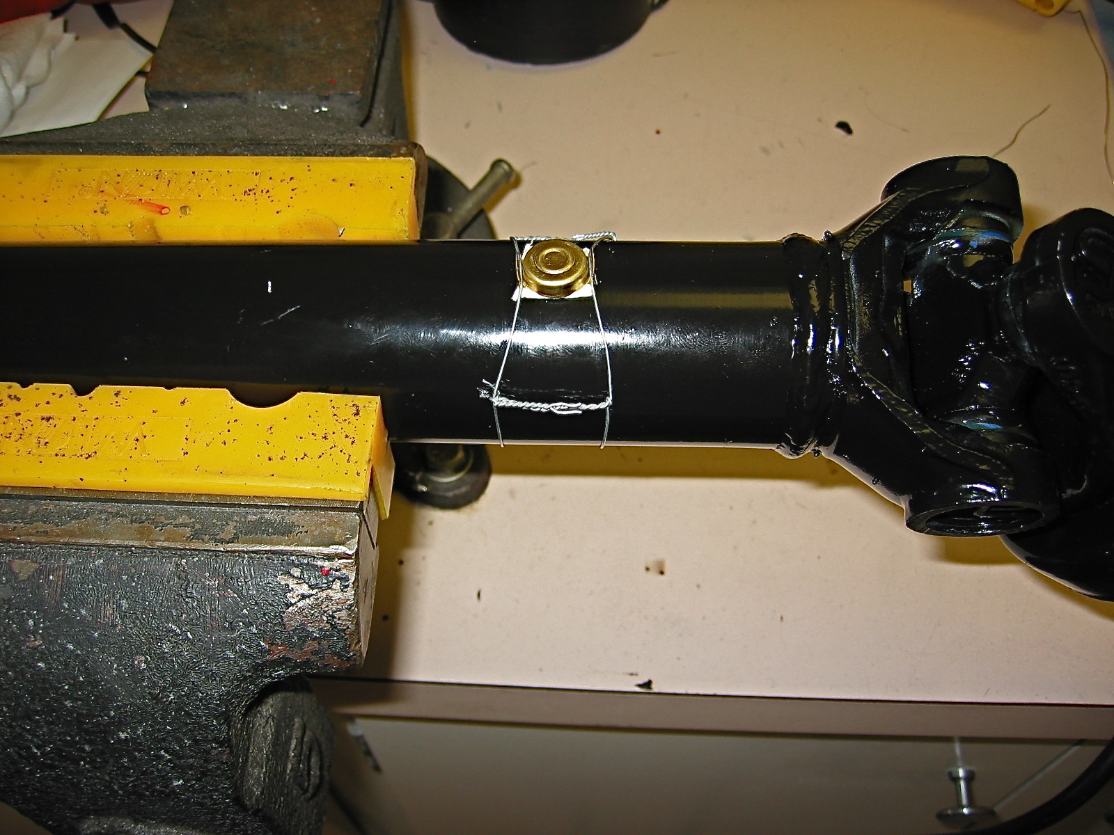
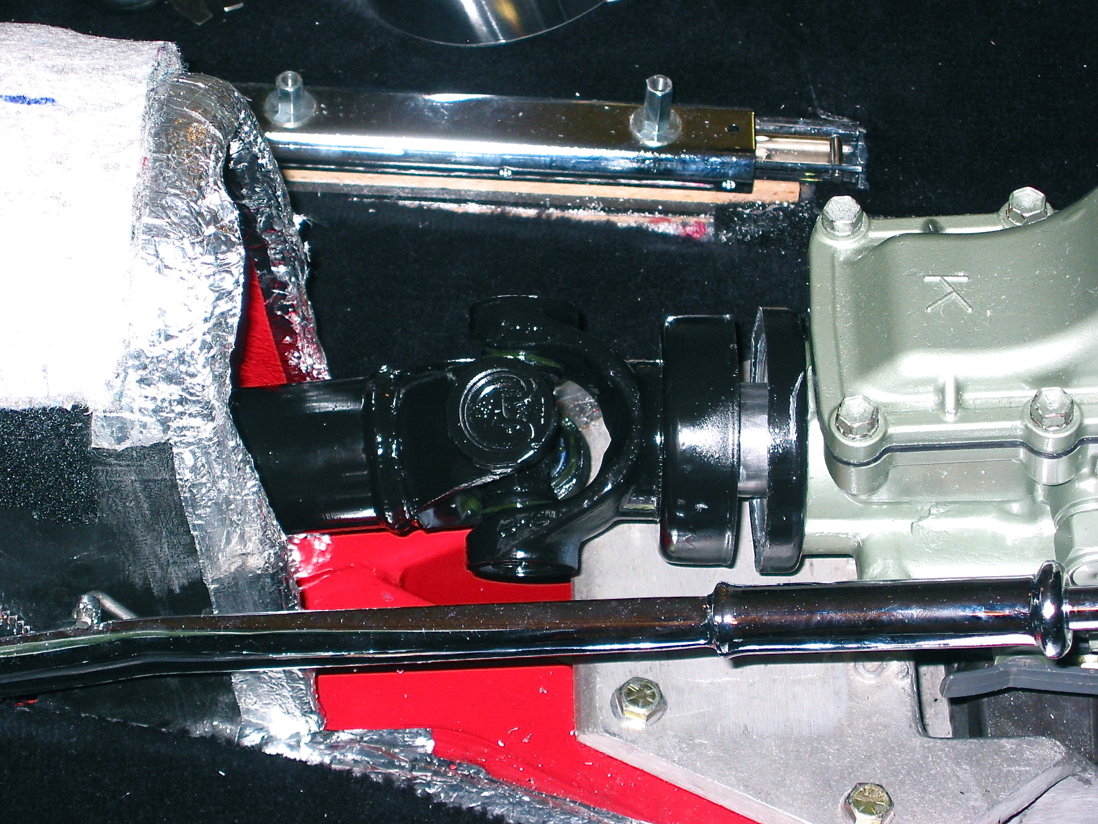
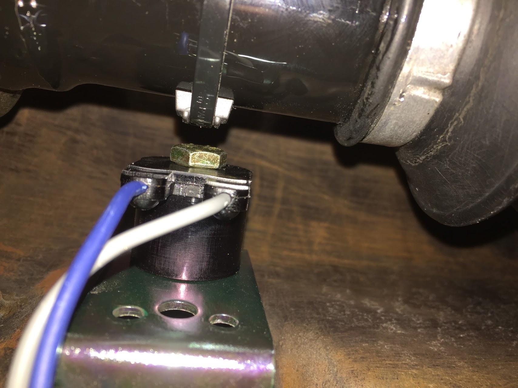
Third, secured the magnet with the long plastic tie strap provided. The ribbed side of the strap is against the magnet and seated between the two ribs on the magnet casing. I then tightened the strap using a screwdriver against the clasp and pulled the strap with pliers. This requires some effort to get the strap tight enough to avoid slippage. As the instructions indicated, I then cut the excess strap flush to 1/16″ from the lock.

Pick-up Coil and Magnet on propshaft
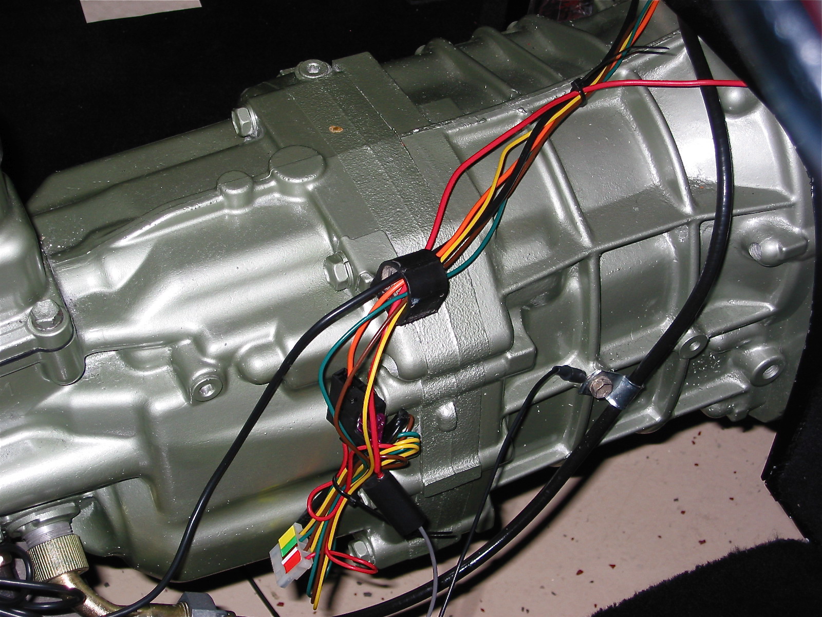
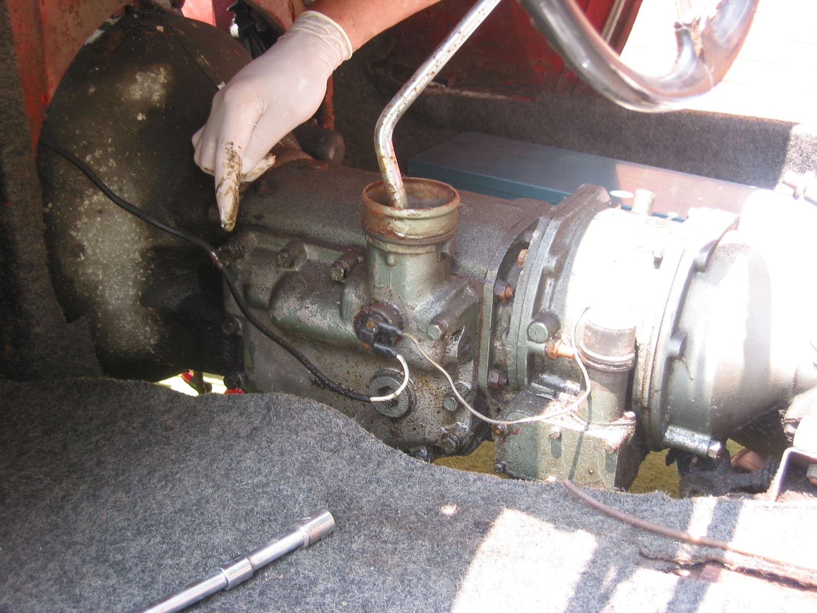
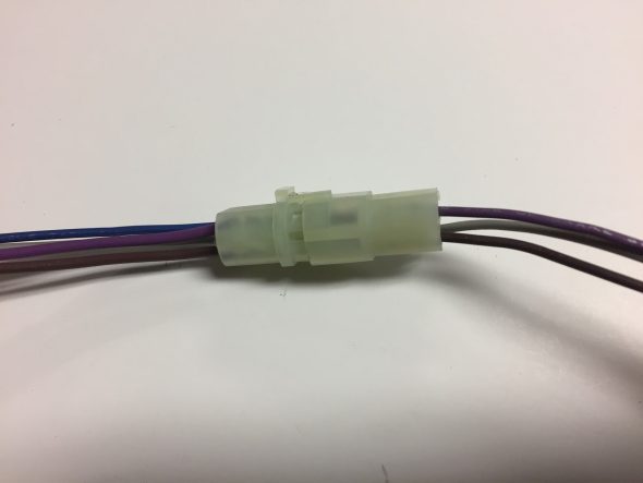
Fourth, I then ran the blue and grey wires from the pick-up coil under the car and up through a rubber grommet in the gearbox tunnel. The wiring then travels under the center console and up and under the dash exiting the firewall and connecting to the clear two wire plastic connector. I temporarily left the blue and grey wires without a connector, but will add the black male connector and cover the wiring in a rubber tube upon final installation. The Grey wire connects to the grey wire near the control module and the blue wire connects to the blue wire. Both will be shortened at final installation as well.
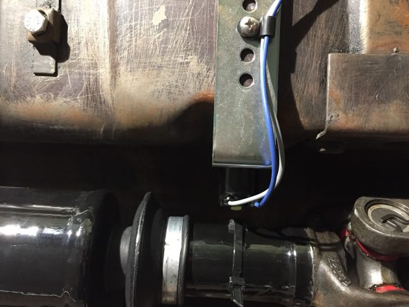
Wiring from Pick-up Coil

Pick-up coil wiring to gearbox tunnel
Pick-up coil wiring exiting Gearbox Tunnel
Pick-up Coil Wiring to Global Cruise Control Module
The female connector with the grey and black wires is identified from the factory with a white label entitled “optional signal generator.”
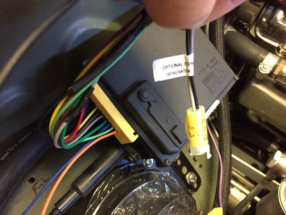
Optional Signal Generator Connector
Attaching the Cruise Cable from the Cruise Module to the Throttle
It is important for safety and proper operation to follow the instructions provided with the kit!
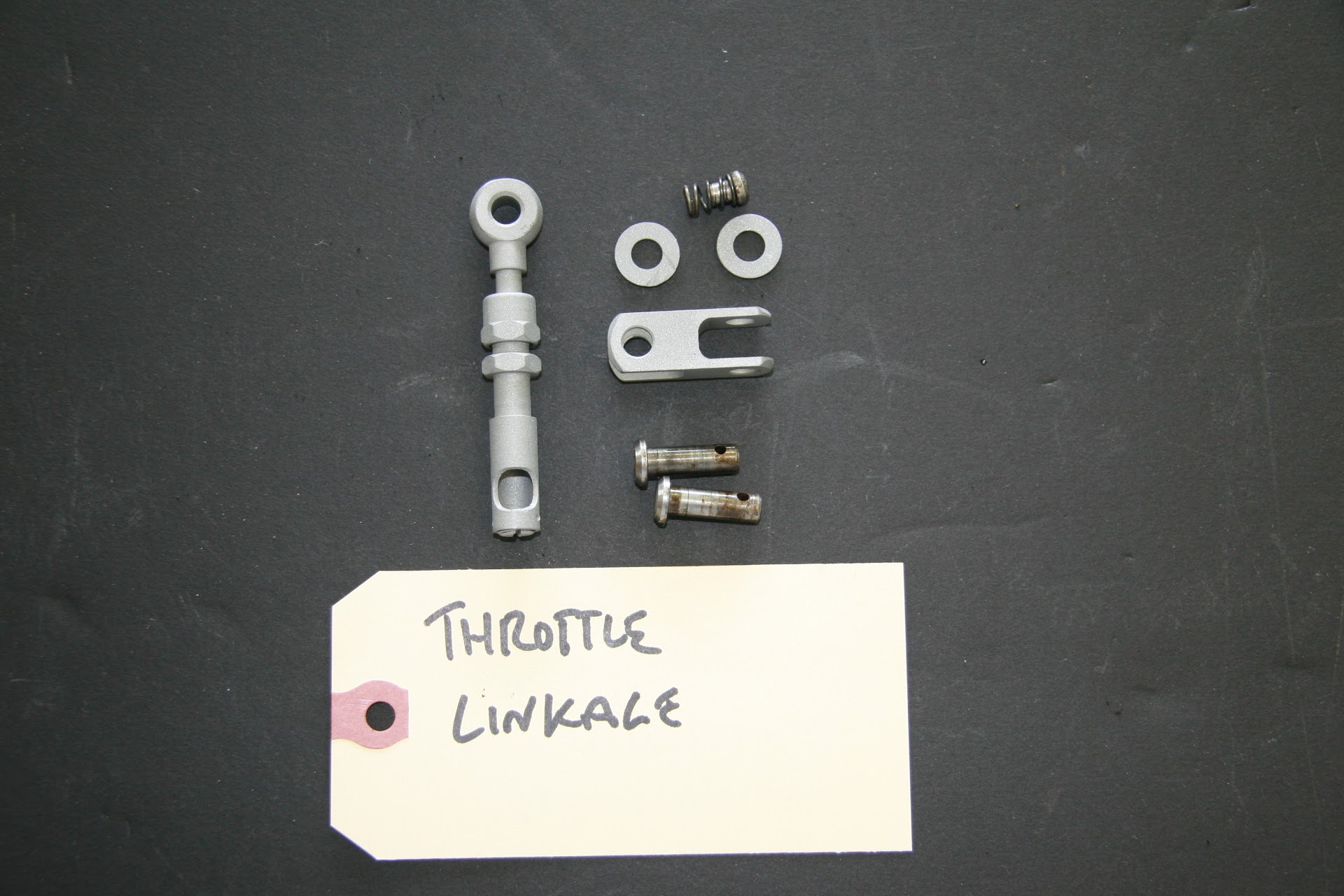
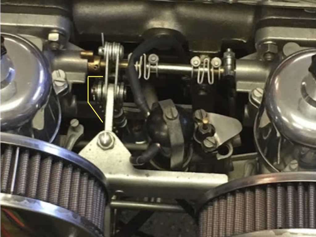
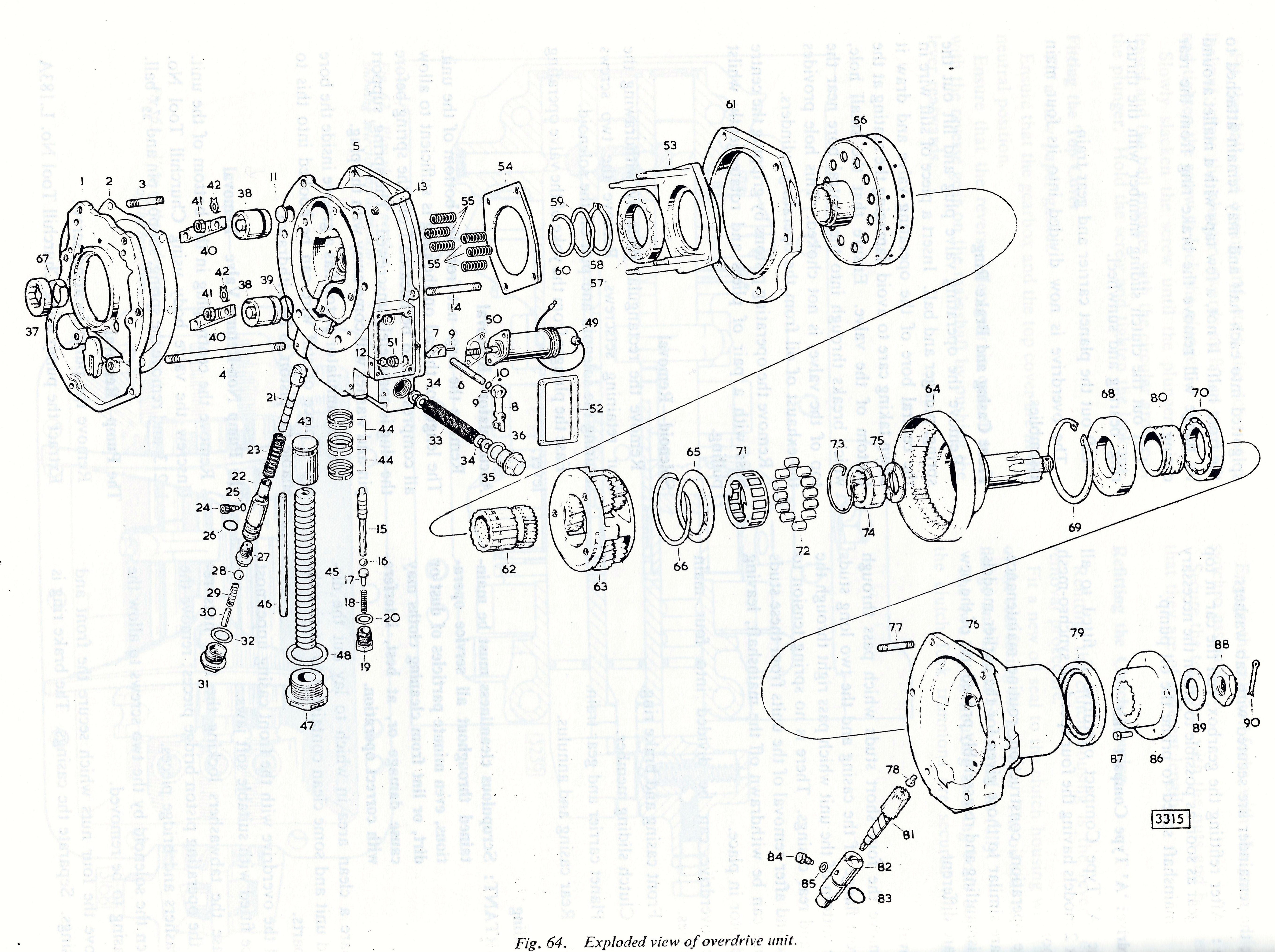
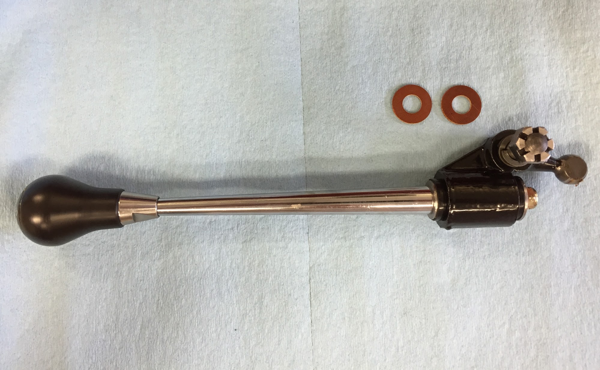
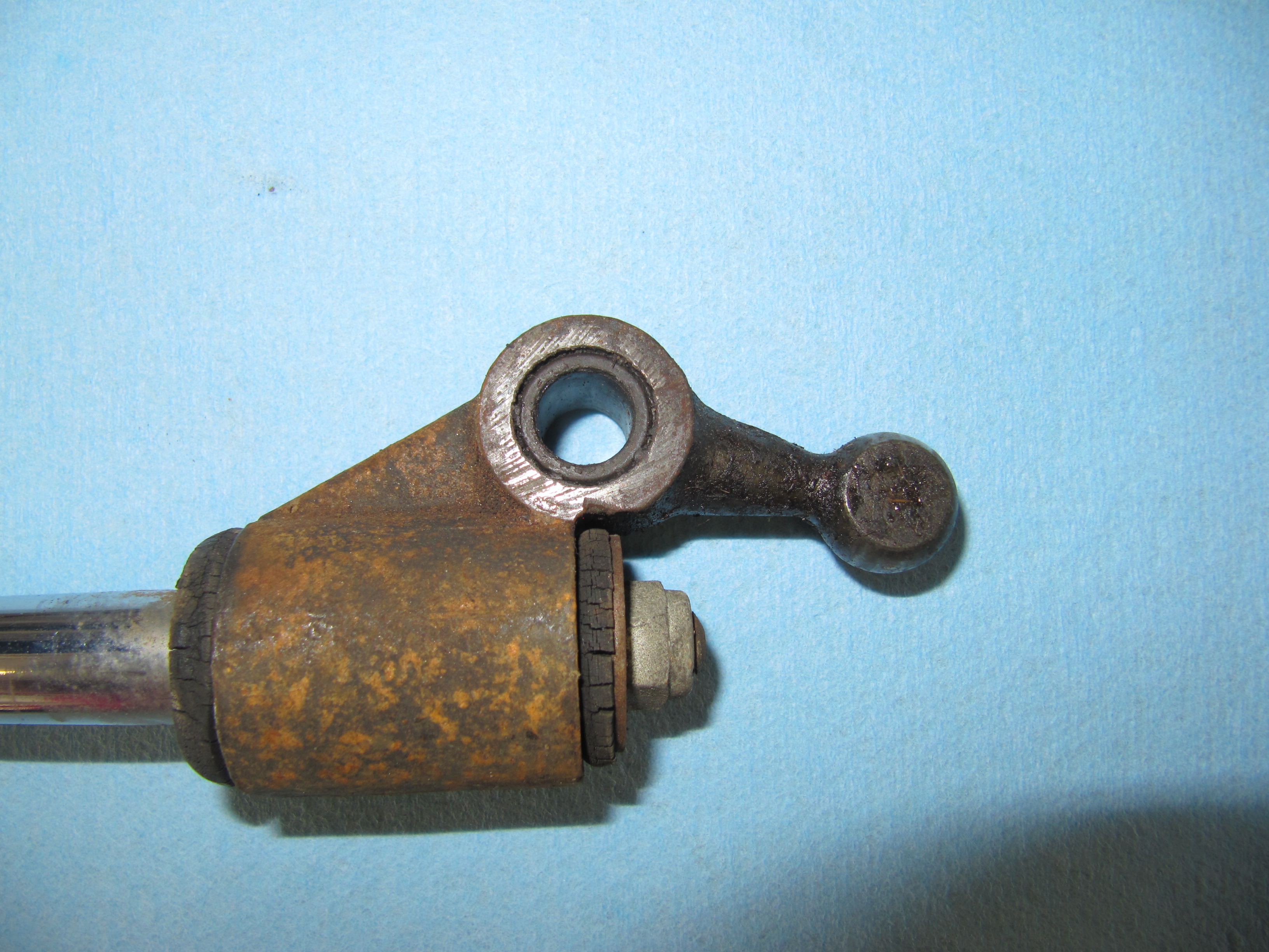
Because of its universal mounting applications, the Rostra kit includes numerous brackets and connectors. You end up using very few of the components that they provide. For the Jaguar 3.8 MK2, one needs to align the cable mounting and the Throttle Link Rod Assembly/Intermediate Throttle Lever.
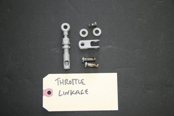
Throttle Link Rod Assembly

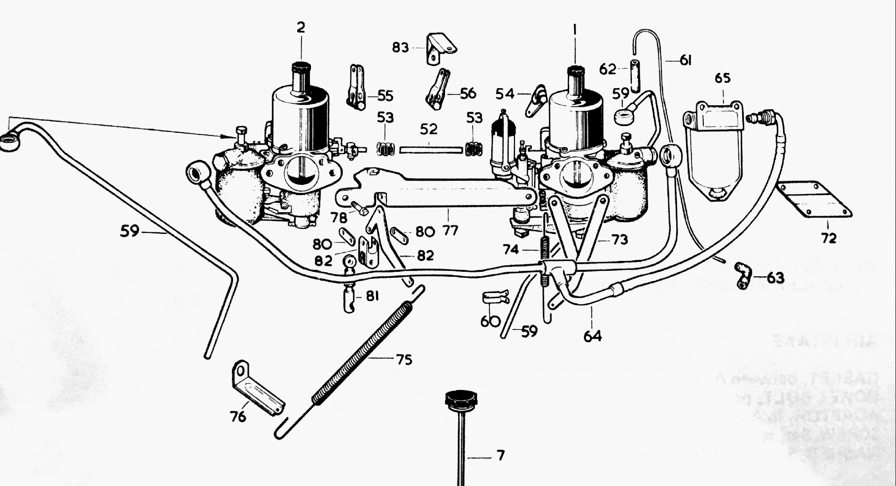
Carb and Fuel Connections Schematic
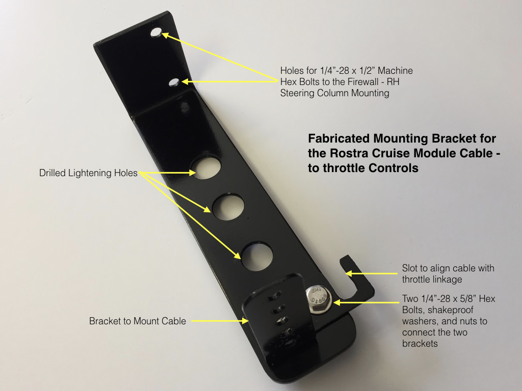
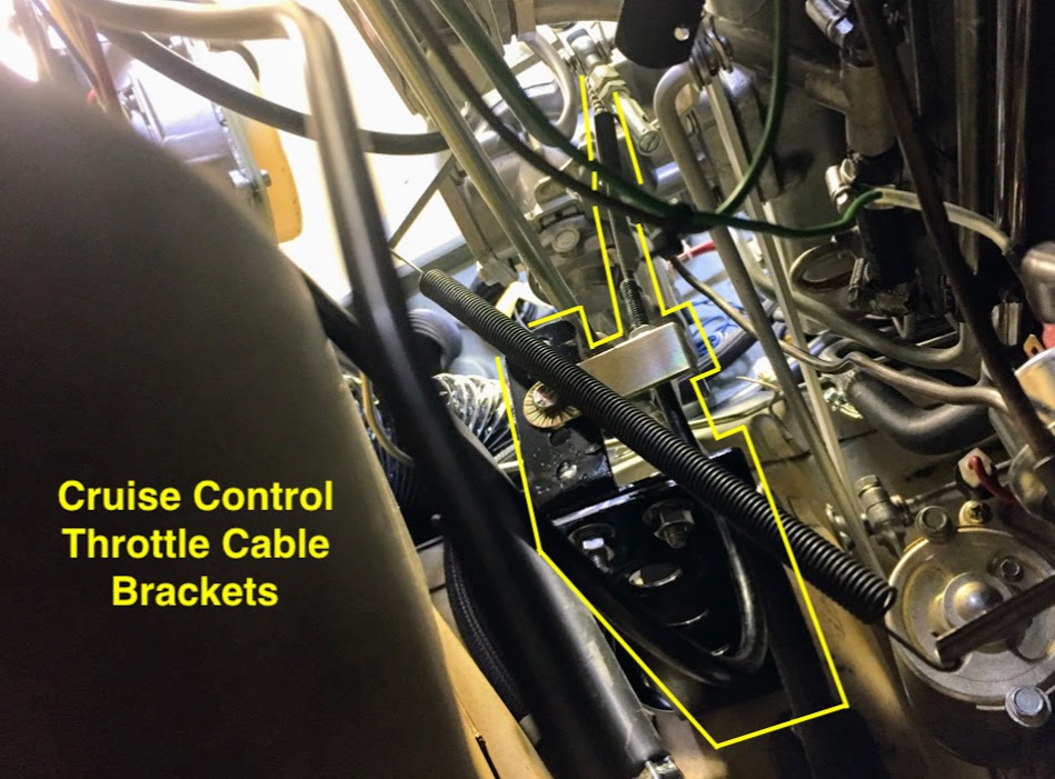
I have “over-engineered” the bracket I fabricated for the cruise module cable, but I like to use existing holes/captive nuts and etc. whenever possible to avoid changes to the car’s body. In this case for the base of my bracket, I used two of the captive nuts available at the cover plate for the steering column on the RH side of the firewall since these are unused given that my car is LH drive.
The second image below shows the bracket and cable installed although it is somewhat difficult to ascertain the components.
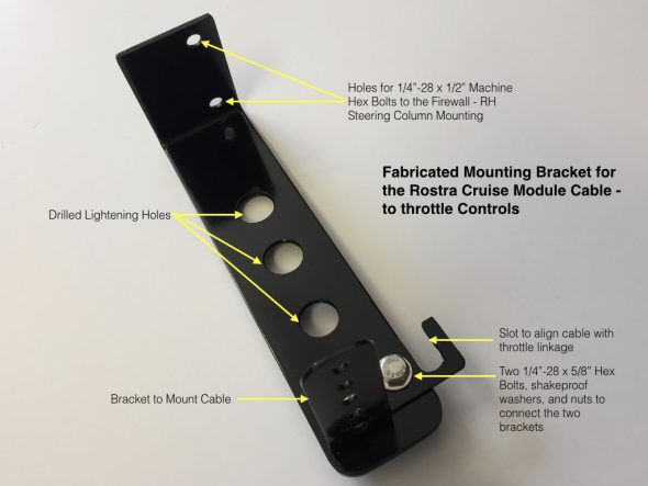
Rostra Crusie Module Cable Bracket
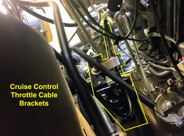
Rostra Cruise Module Cable Brackets Mounted
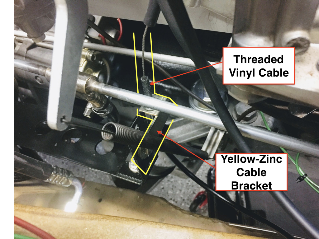
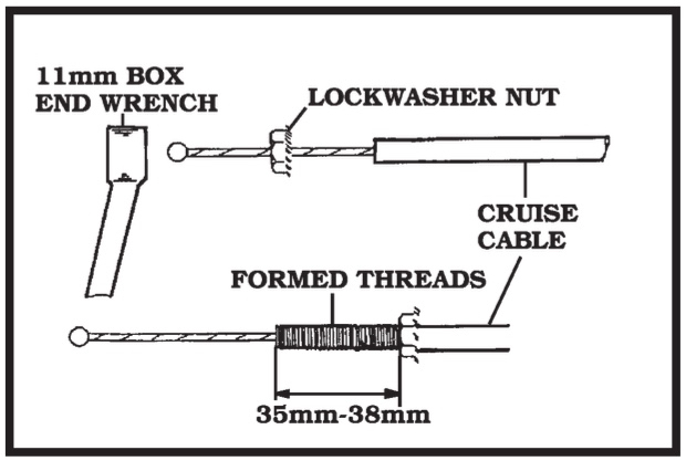
As can be seen in the image above a yellow-zinc bracket attaches to the black bracket I fabricated and this zinc bracket actually anchors the throttle cable with two securing nuts. The threads on the vinyl covered throttle cable are actually formed by turning the lock washer nut clockwise on the cable.
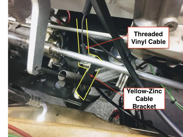
Cable Connection to the Jaguar Throttle Assembly
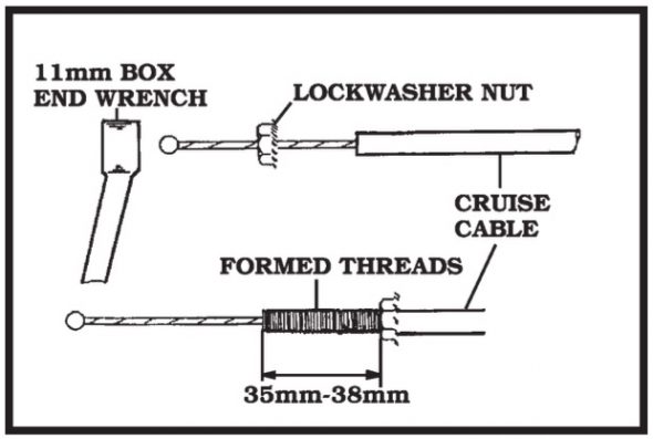
Cable Sheath Threading
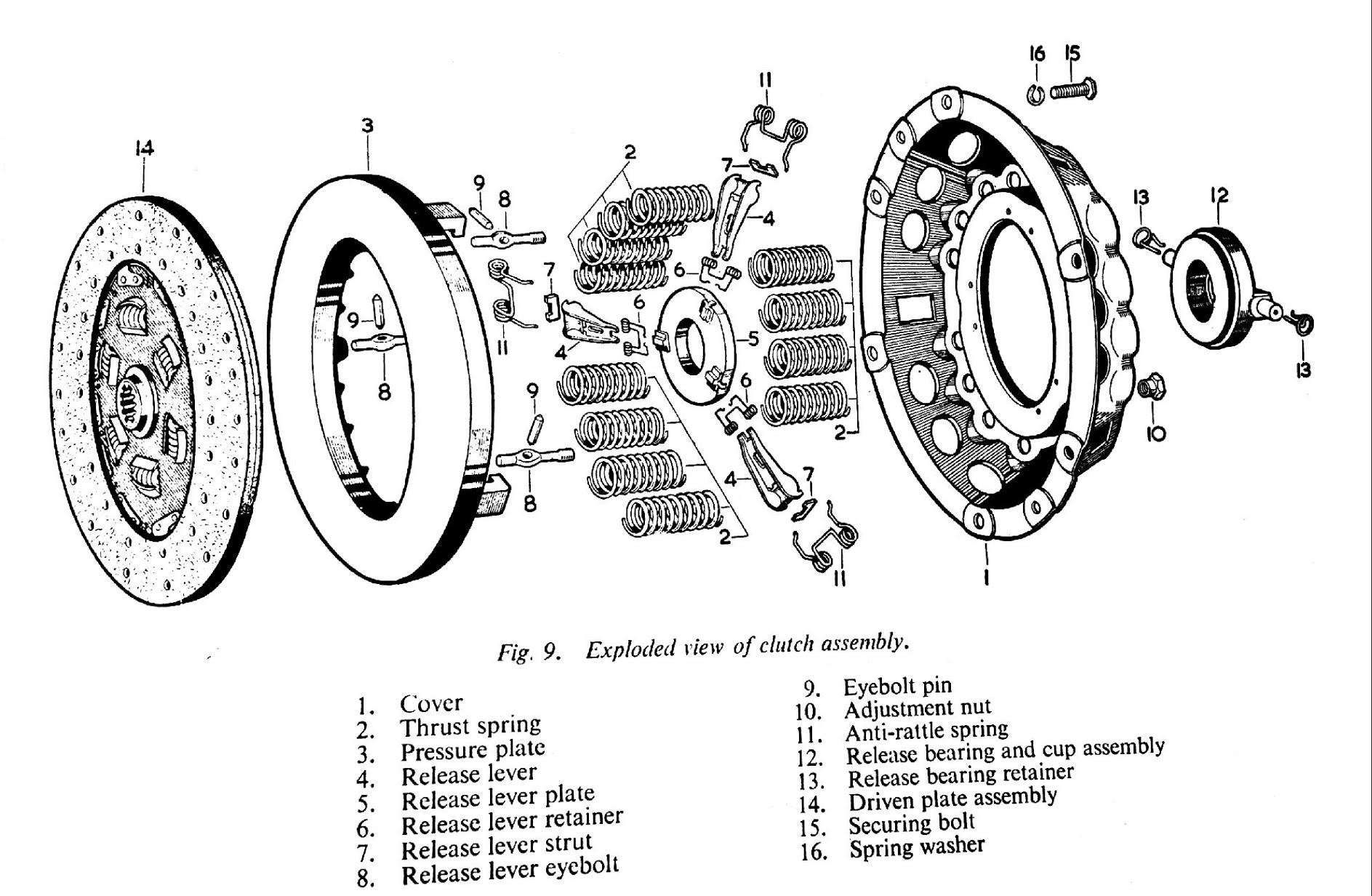
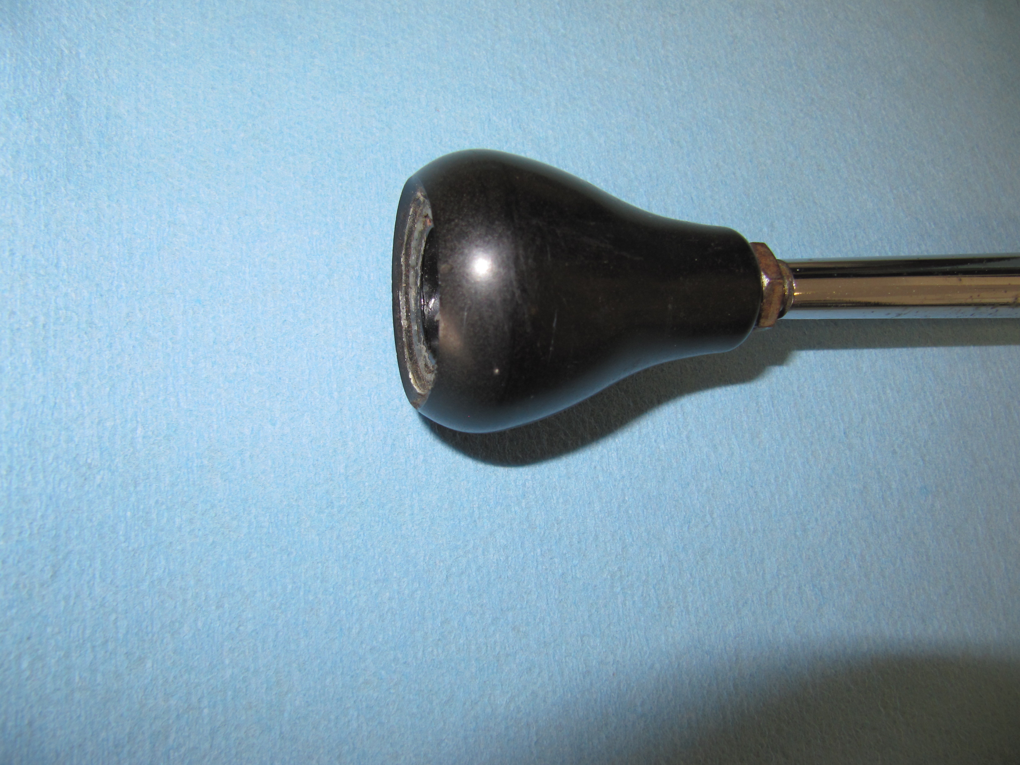
Many different cable ends are available in the kit. I used the eyelet shown in the image below. It fit perfectly on the clevis pin used in the Jaguar throttle assembly.
Cruise Module Cable End Connections
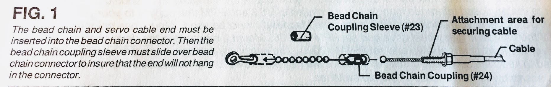
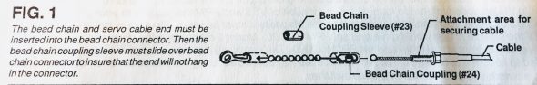
Throttle Cable Travel – This is a very important step. Failure to determine throttle cable travel could cause damage to your vehicle and/or Global Cruise.
The throttle cable travel must be at least 41mm (1-5/8″). Length is added by using the beaded chain provided in the kit. As shown in the image above, bead connector coupling sleeves must be used over the connectors.

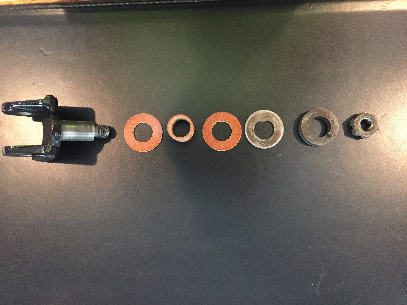
Cruise Control Cable-Clevis Pin Connection to Throttle