Installing the Audiovox CCS-100 Cruise Control in a 1960 BT7
April, 2008
I decided to install a cruise control system in my car near the end of a complete restoration. The engine was in place, but the front shroud, wings and doors were yet to be installed. It seemed like the perfect time to add cruise control. Having seen the Audiovox unit installed in several cars at some recent Conclaves and Encounters, I knew it was the one for me simply because I love my modifications to be discreet when possible (my car has many “personalizations”). The Audiovox control module fits inside the gearbox cover chrome ash tray, and can be completely concealed. Knowing that other Healey owners had reported that the Audiovox unit performed in a satisfactory manner, I placed my order from J. C. Whitney and started thinking about how I would install it on my car.
My car has been converted to negative ground.
I have prepared this “tutorial” to try to be of help to those who might be interested in adding cruise to their Healeys, but a word of caution is appropriate. My notes are no substitute for the very comprehensive instructions provided in the kit, especially when it comes to the wiring. As I mentioned, my car has a number of modifications and that means that your experience may well be different than my own.
First, I want to thank a few people who provided responses to my enquiries concerning the addition of cruise control. Alan Teague and Carl Brown were both particularly helpful, as were Len Hartnet and Bob Slater. Al Malin shared some images of installations he had seen at the Vermont 2007 Conclave. They are included below; however, I am afraid I don’t know the owners of the cars so I cannot give proper attribution. The October 2002 issue of Healey Marque contains an article entitled Healey Cruise Control, by Dick Lunney and John Jones that I also found of great assistance. I definitely recommend reviewing the article before you undertake adding cruise control. Dick installed the cruise on his BN2 and John on his BN7. Everyone I consulted used the Audiovox system with the exception of Bob Slater, although I do not know what brand he used. All of my commentary is in reference to the Audiovox CCS-100 only.

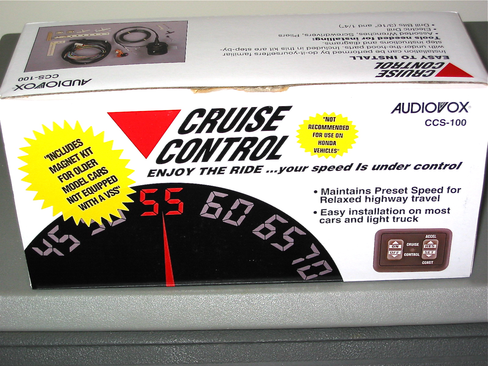
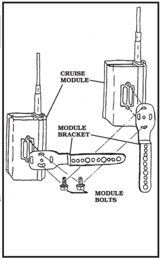
Audiovox Cruise Control Image 1
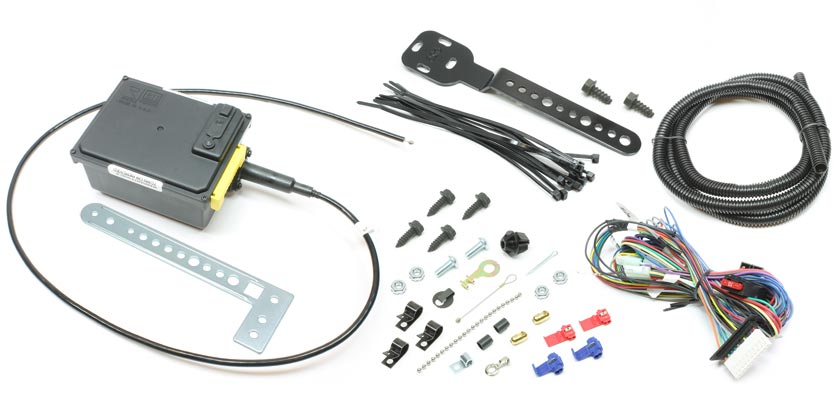
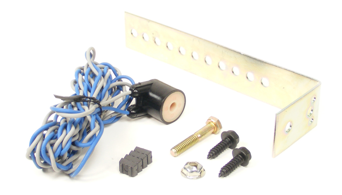
As one will quickly deduct from a preliminary review of the instructions, this unit is designed for a multitude of vehicles, but as you might guess Austin Healeys are not listed in the various brands and models of cars identified in the packaging. Because of the somewhat universal application, the kit comes with quite an array of fittings, brackets and linkages that are of no use with our car and they can therefore be set aside.
The primary components of the system are: 1. The vacuum canister and vacuum connection; 2. The magnet and sensor for the propshaft; 3. The throttle linkage; 4. The control module; and 5. The wiring of the system.
I will attempt to describe each.
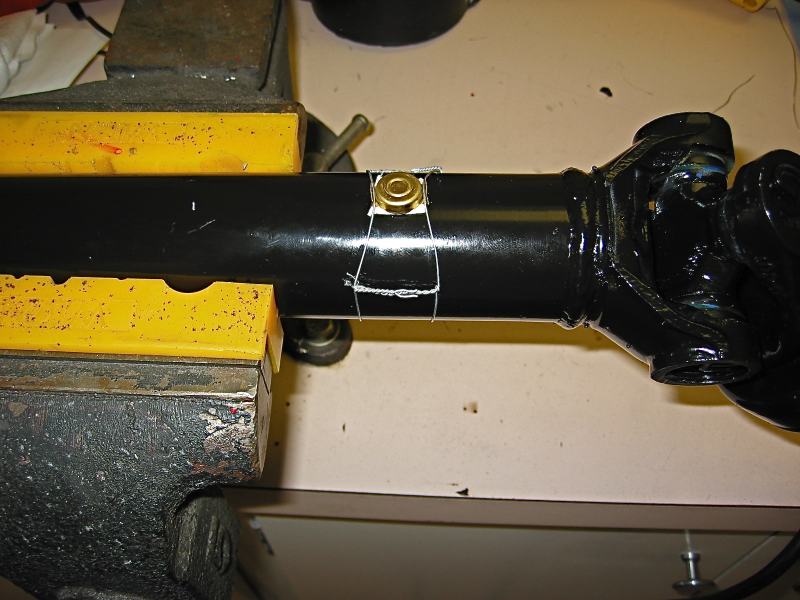
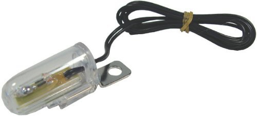
I began my installation with the magnet and sensor for the propshaft. This necessitates the removal of the gearbox cover. I aligned the magnet and the sensor with the propshaft in the car, but after locating both components, I actually found that I could do a much better job of wiring the magnet in place with the provided safety wire if the propshaft was on my workbench. The Healey requires the use of only one magnet (two are supplied).

Cruise Control Propshaft Image 2
It is installed with a double-sided sticky foam pad on the propshaft. My propshaft was new and freshly painted. If yours is not, you will need to clean it with sandpaper, brush and solvent.

Safety Wire Twister Tool Image 3
If you want to do a nice job, I highly recommend using safety wire twisting pliers. They make the job much easier and result in higher quality work. I got my pliers from Aircraft Spruce, but I am sure they are readily available from other suppliers as well.

Cruise Control Propshaft Image 4

Cruise control Propshaft Image 5
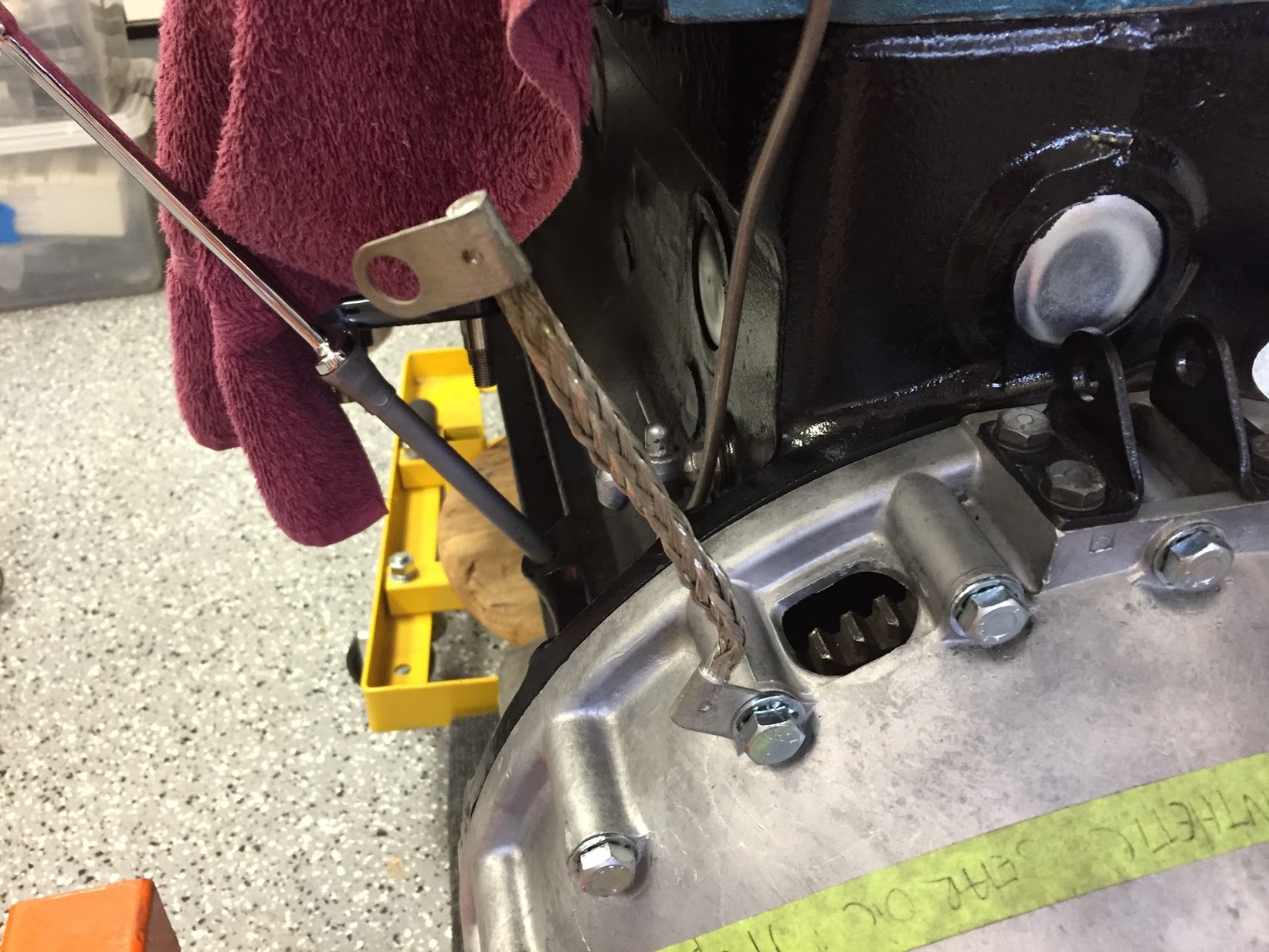
Note that when you secure the magnet to the shaft that you have the two “ears” in the proper position to be wired in place. The wire “snaps” into the ears and you can hear it “click.” Pulling the wire apart at the joint helps to tighten the assembly on the propshaft, and really does function much better than I ever would have suspected. You may have noticed I am using a propshaft yoke for a Toyota gearbox as I have installed the Smitty 5 speed conversion in my BT7.

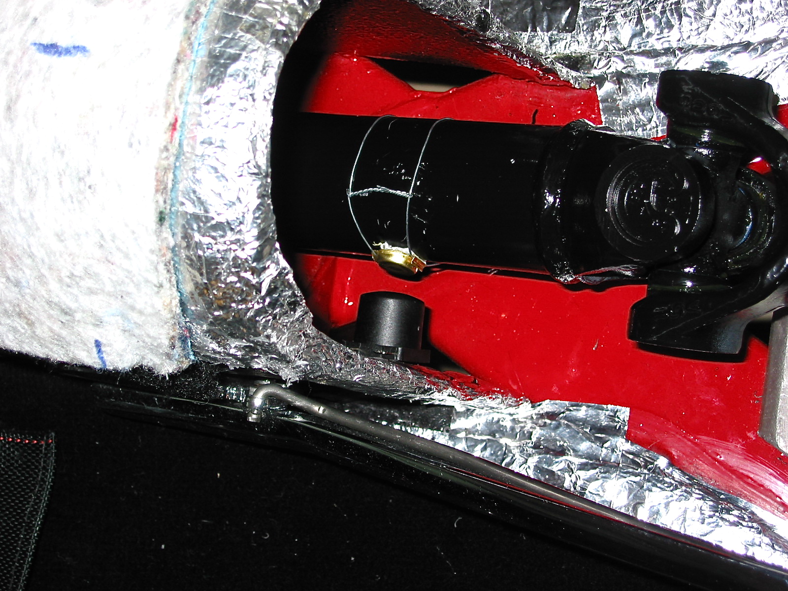
Cruise Control Propshaft Image 6
Your installation may be different, but in my case I was able to simply drill a hole into the side of the gearbox tunnel and fasten the magnet sensor with the nut and washer provided. Depending upon your situation you may need to use one of the brackets provided in the kit for the sensor. The sensor must be pointed directly at the center-line of the propshaft with a 3/8” gap between the sensor and the magnet.

Cruise Control Propshaft Image 7

Cruise Control Propshaft Image 8
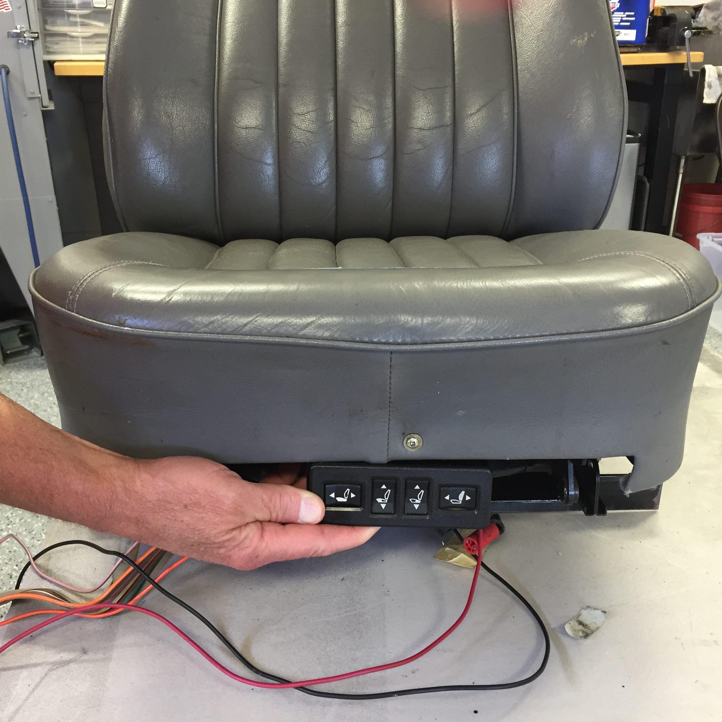
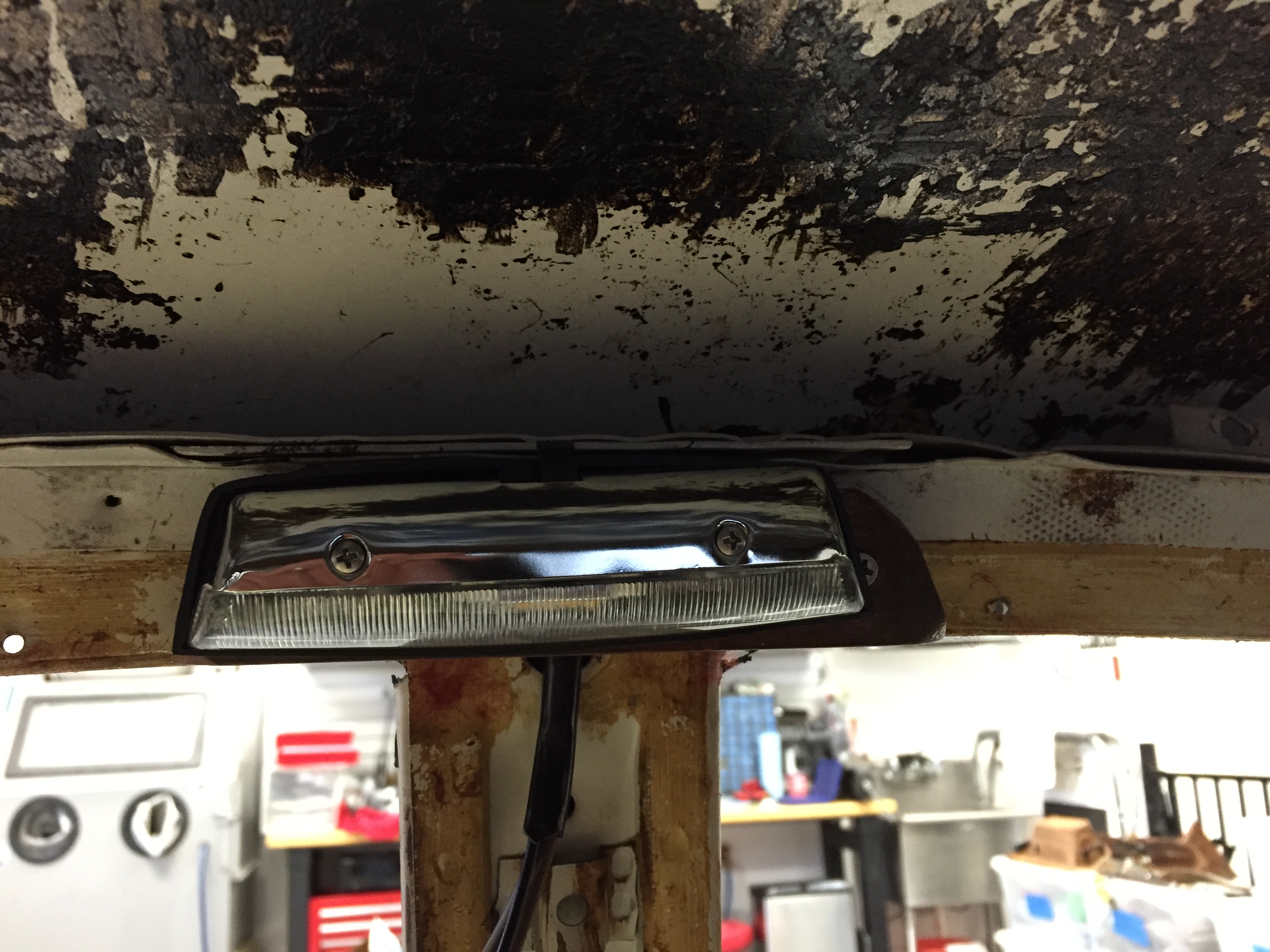
Cruise Control Module or Panel
My next step was to install the cruise control module or panel in the ash tray. You may elect to place it on your dash fascia, console or a custom panel. The routing of the wiring needs to be considered in determining the best location for you and your car. I decided that I wanted to run all of the wiring associated with cruise control under the gearbox cover and the gearbox extension. Others have simply run the wiring under the carpet.
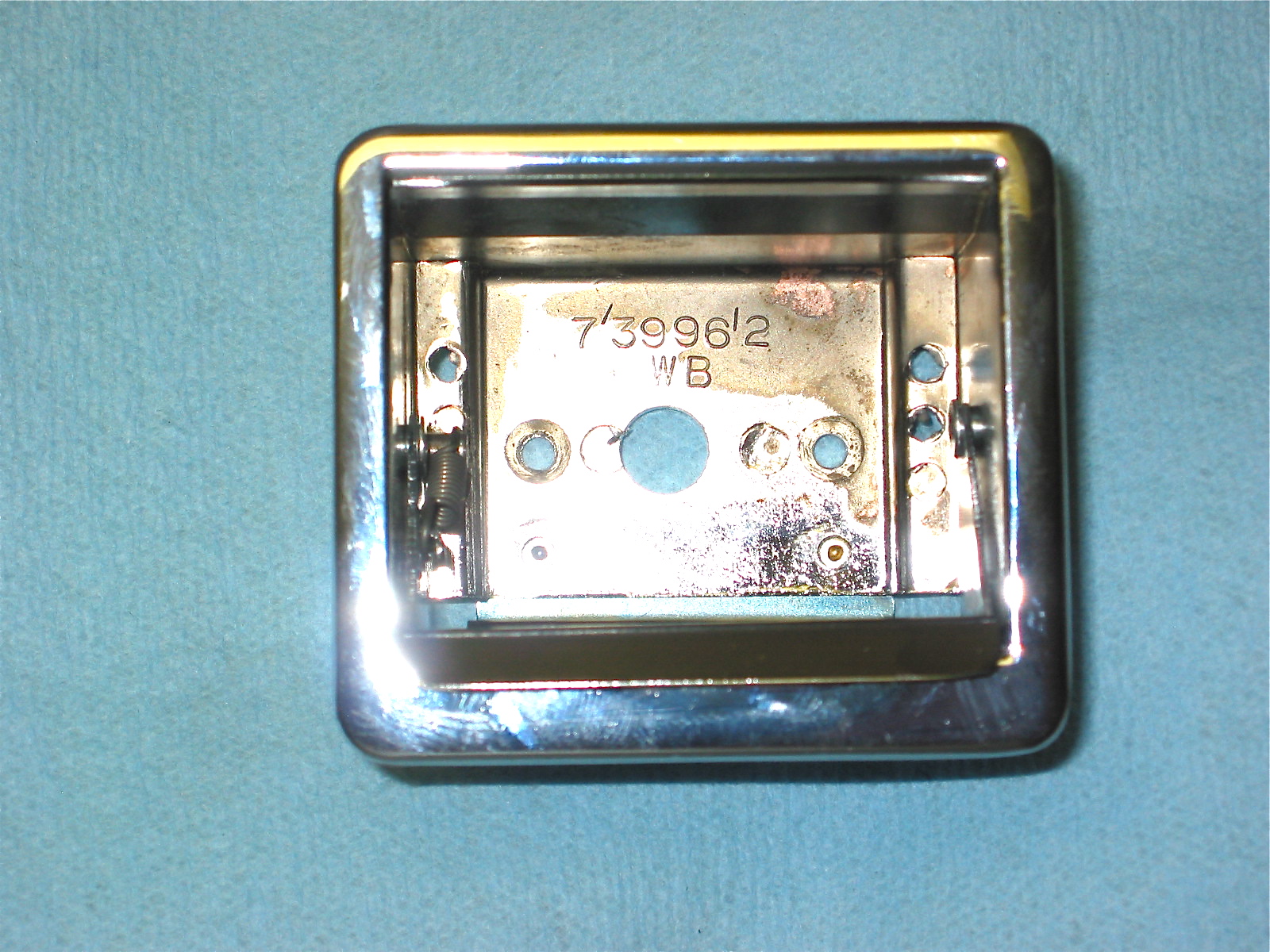
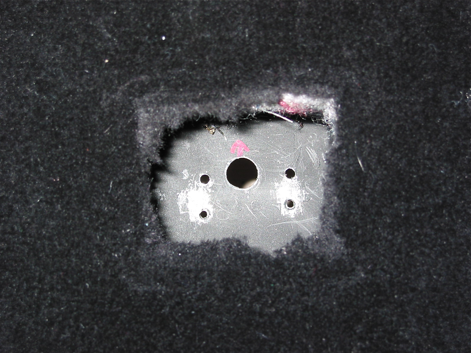
I drilled a ½” hole in the center of the bottom of the ash tray and in the ash tray bracket that is part of the gearbox cover. I carefully smoothed the edges of both holes with a file. You will note that my ash tray is mounted backwards and the bracket has a couple of extra holes (that is a long story, unrelated to the cruise control installation). The control module can then be inserted into the ash tray with the wiring connected to the module pulled through the two holes.

Modified Ash Tray for Cruise Image 9

Modified AshTray for Cruise Image 10
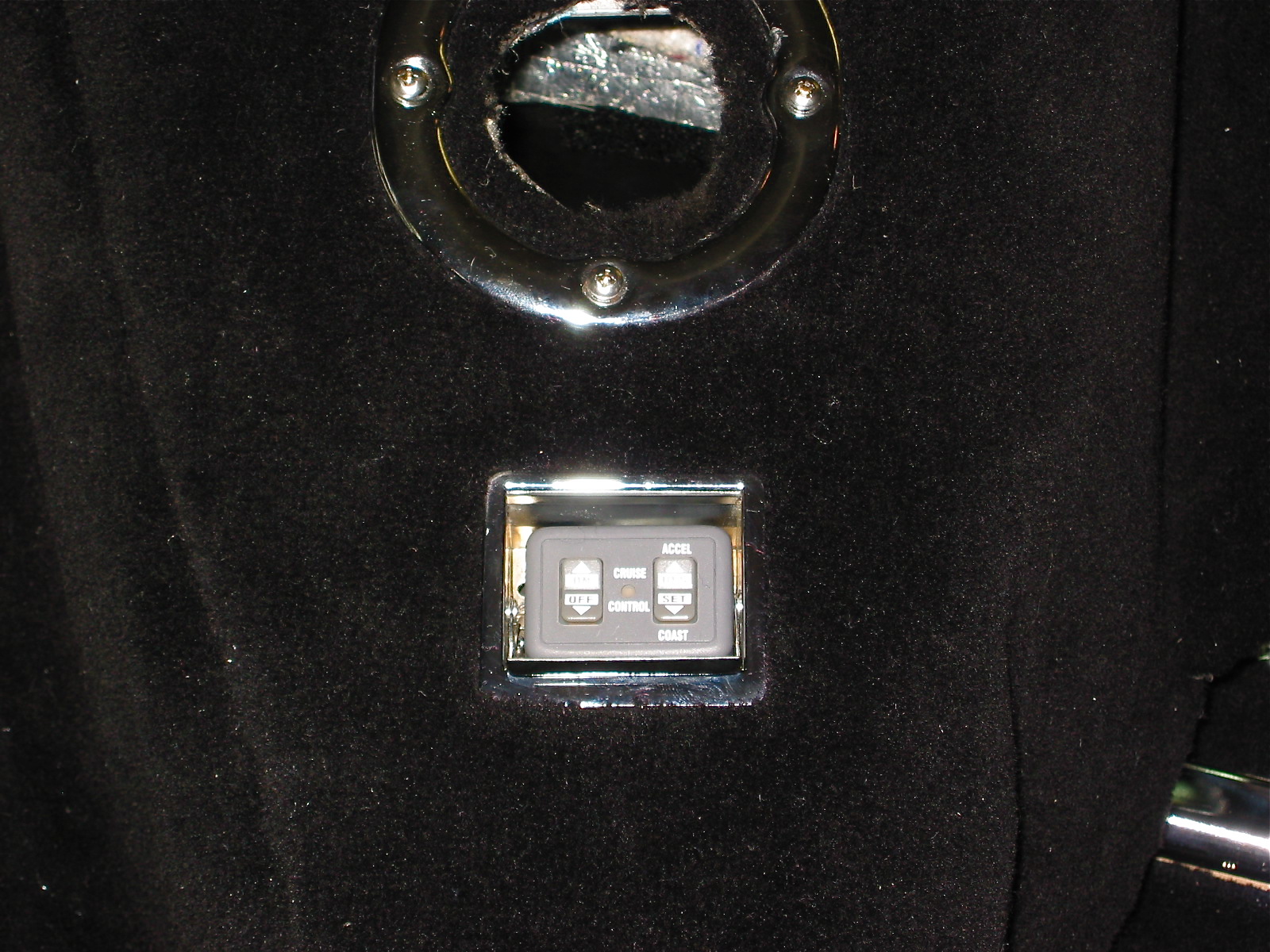
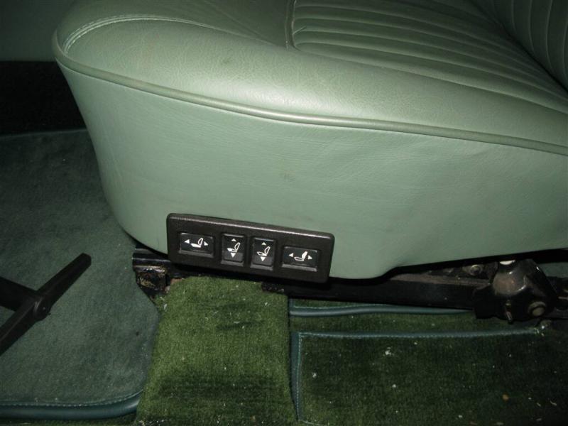
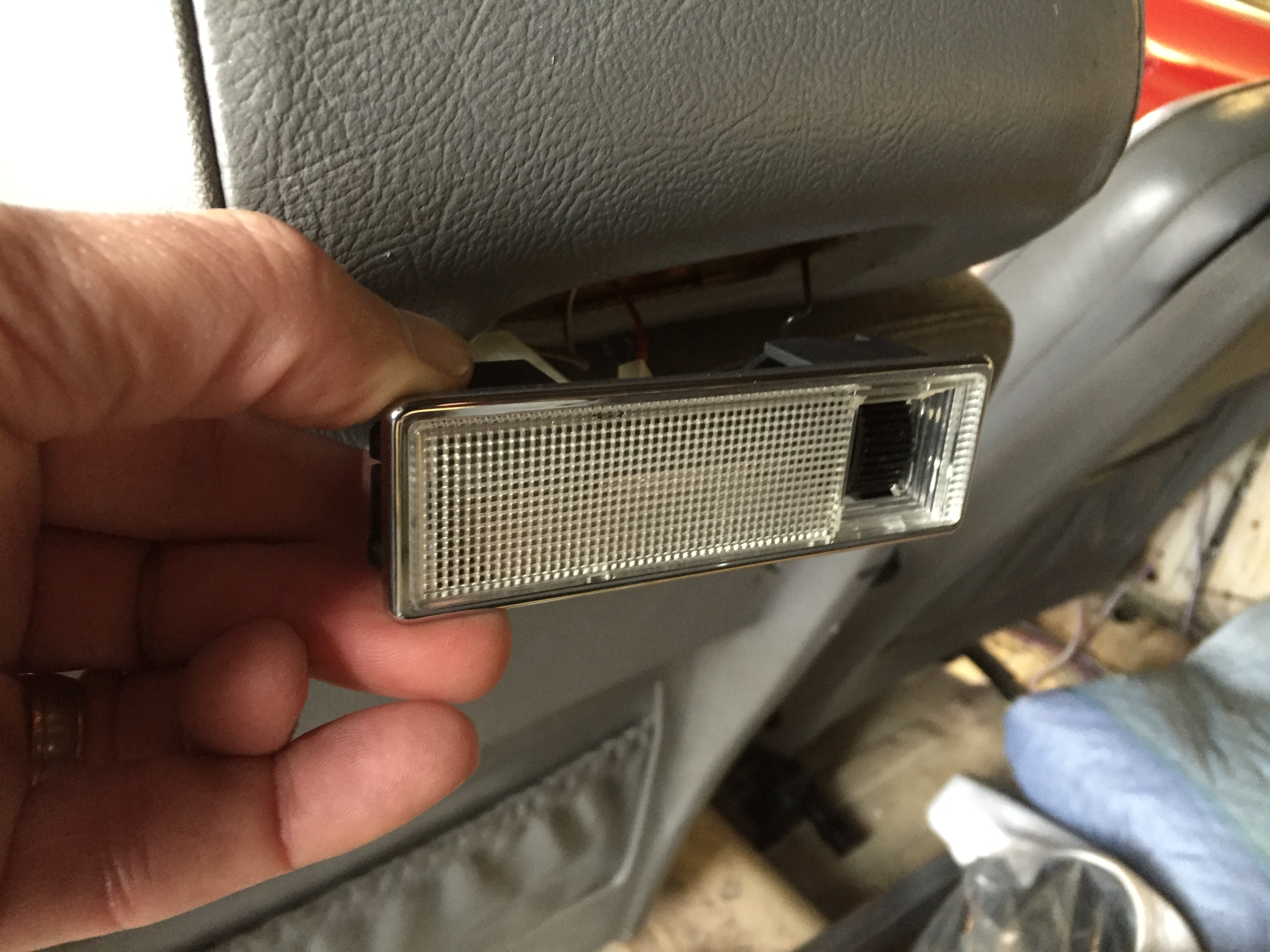
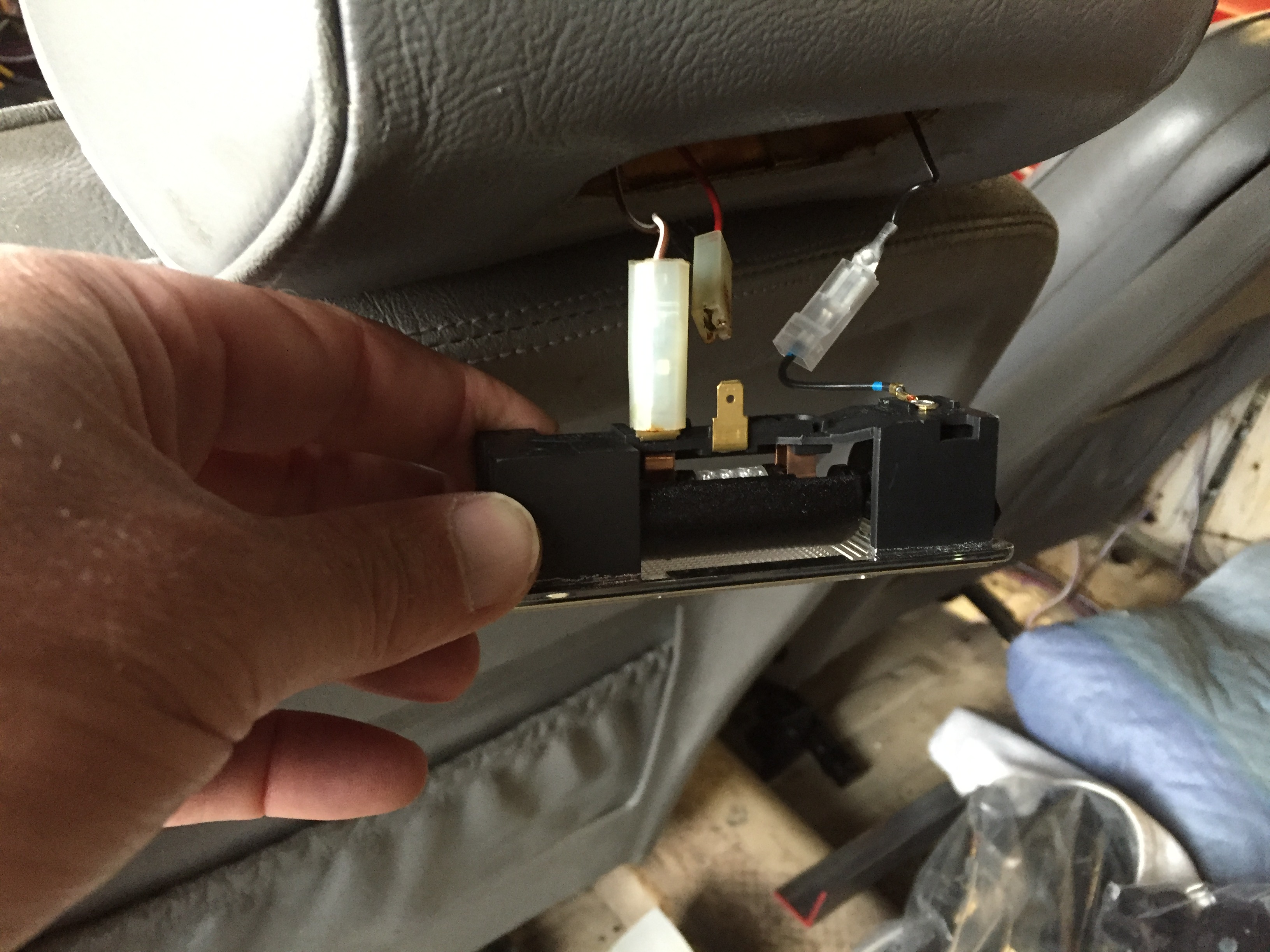
You will need to form some type of spacer to sit in the ash tray below the control module otherwise it will “float” in the space. Styrofoam, or a small block of wood will work. The module has a two-sided sticky adhesive pad on its rear side for location on a flat panel. The size of the module does make for a very neat installation. My BT7 installation ended up looking like this:

Cruise Control Panel Installation Image 11
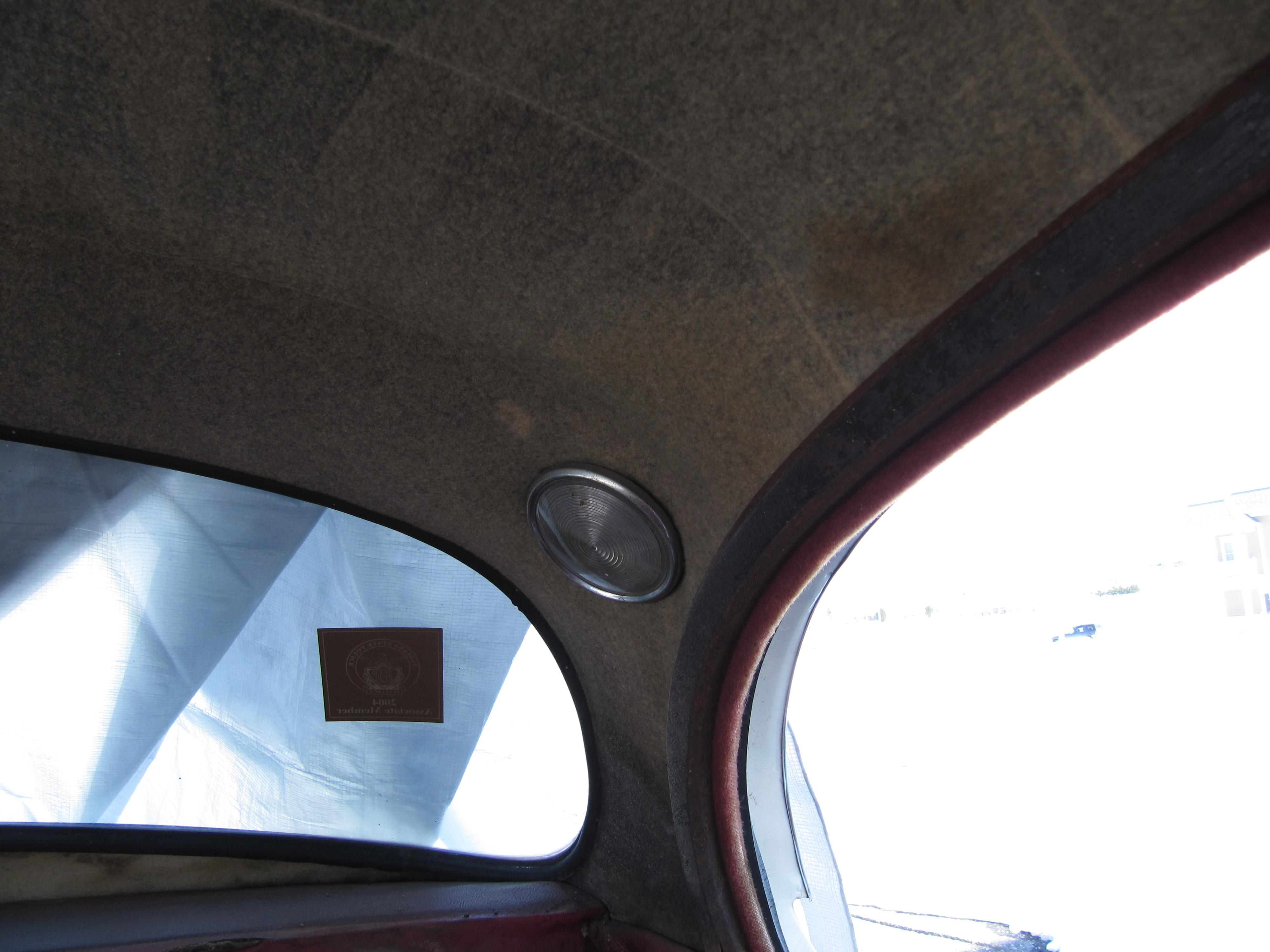
Alan Teague’s BJ8 Console install:

Alan Teague’s BJ8 Console Install Image 12
Herb and Bonnie Chrestie’s Dash Fascia Install:

Herb and Bonnie Chrestie’s Dash Fascia Install Image 13
Programming and Installing the Servo Canister
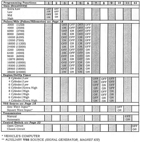
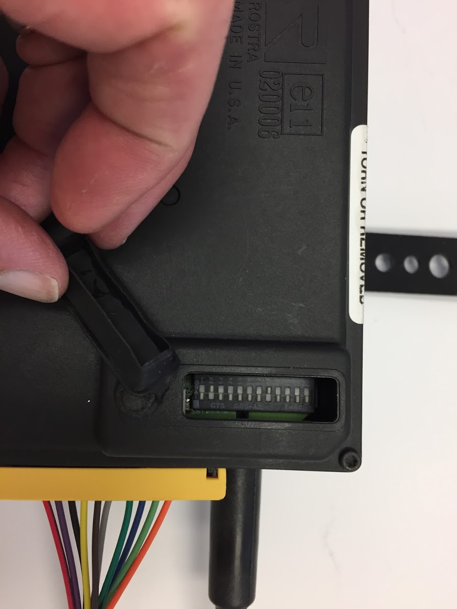
This is the next task. On the back of the vacuum canister there is a small plastic cover that is removed to reveal seven dip switches. The instructions provide more detail on the dip switch settings, but for the six cylinder Big Healey three switches are set to the “on” position and four are set to the “off” position.

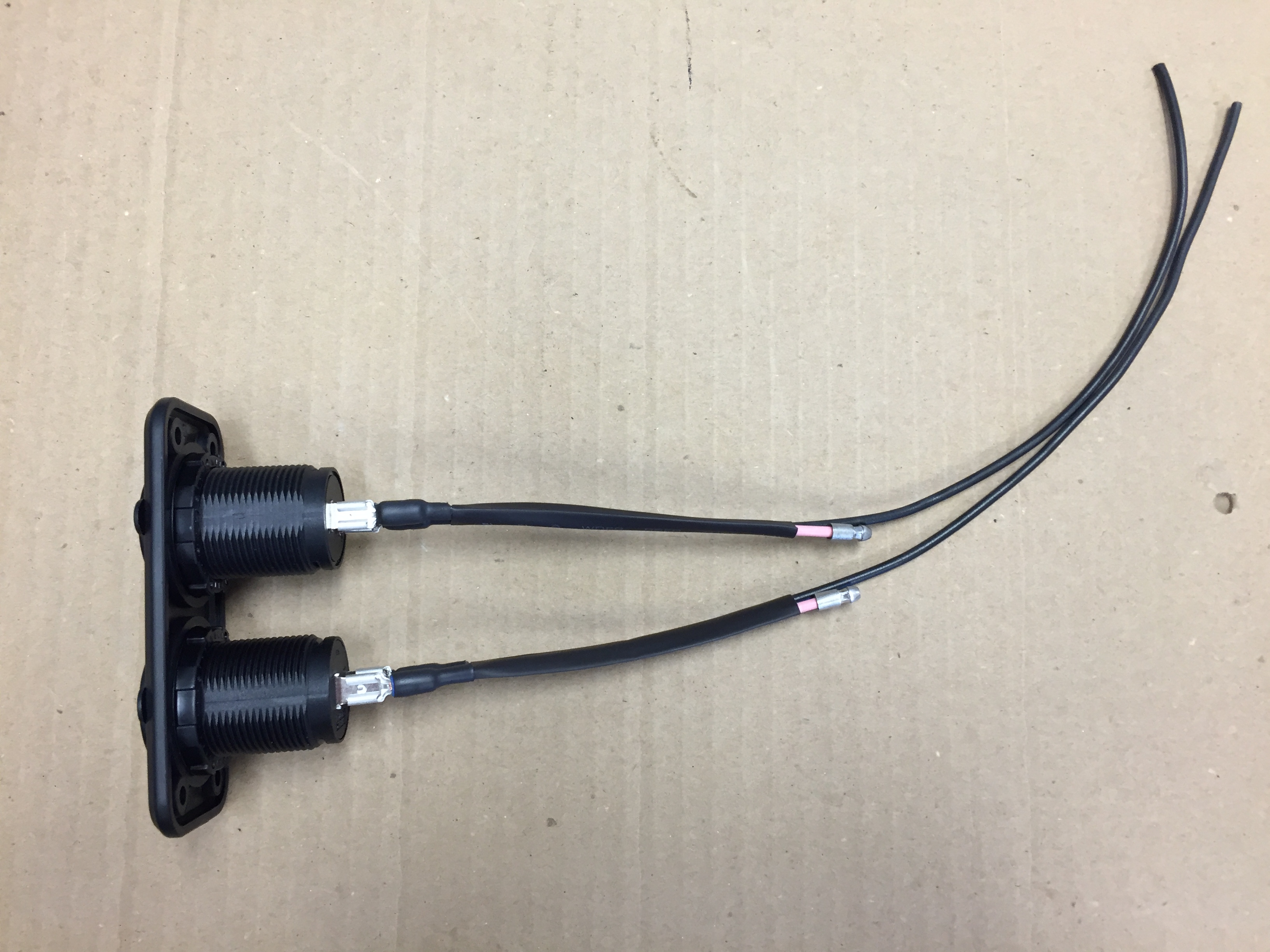
Servo Switch Image 14
Those that are set to the “on” position are numbers 1, 3 and 7. For all manual transmission cars, the small black jumper connector located on the left side of dip switch #1 is removed. The 10-pin plastic wiring harness connector is then plugged into (snapped) place on the dip switch panel, and the wires are folded back. The plastic cover is then replaced with two small self-tapping screws.

Servo Switch Image 15

Servo Switch Image 16
Locating the Vacuum Canister
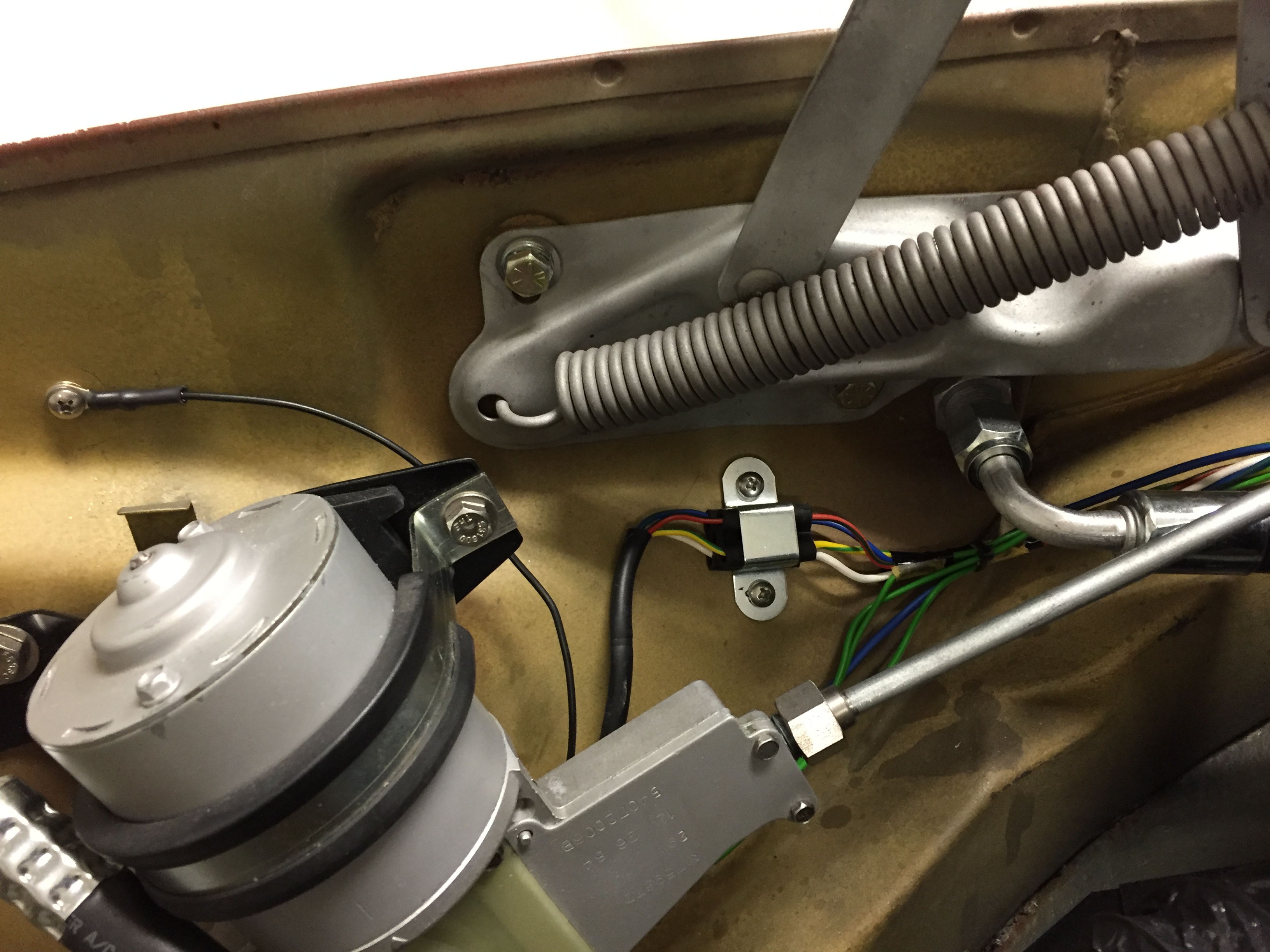
Locating the canister in the vehicle was the most challenging part of the project for me. As I mentioned previously, I have a number of modifications on my car that meant places that were used by others who have installed this unit were not available to me because something was already located in the spot where the canister might go.

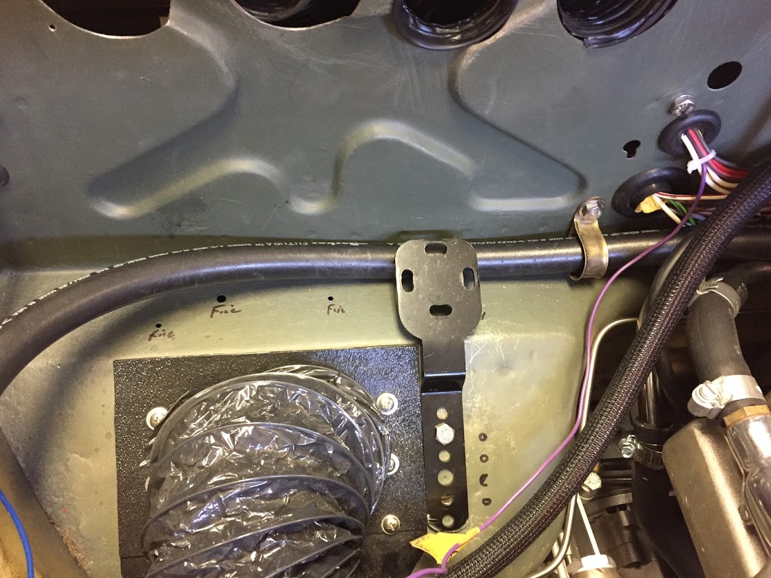
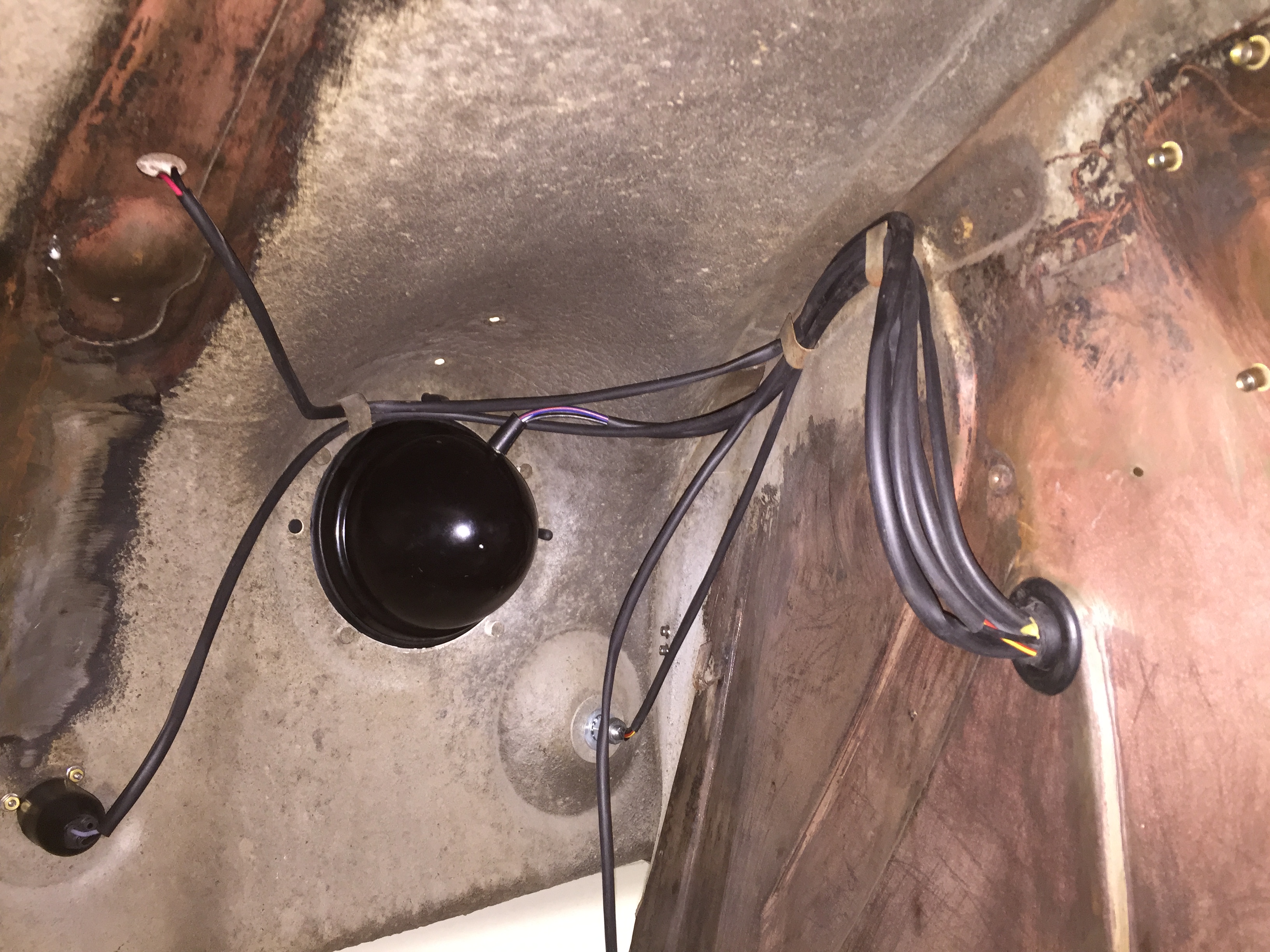
Vacuum Unit Install Image 17
Al Malin took the photo to the above at the Vermont Conclave that shows the canister mounted to the right firewall brace. That didn’t work for me because I already had placed a radiator overflow tank there. This location might work for you, but then again you might wish to make the canister less visible.

Vacuum Unit Install Image 18
Several people have reported mounting the canister on the fresh air box beside the steering column. Carl Brown and Alan Teague selected that location. It might also be mounted below the left wing, but you cannot get too low due to heat from the exhaust.
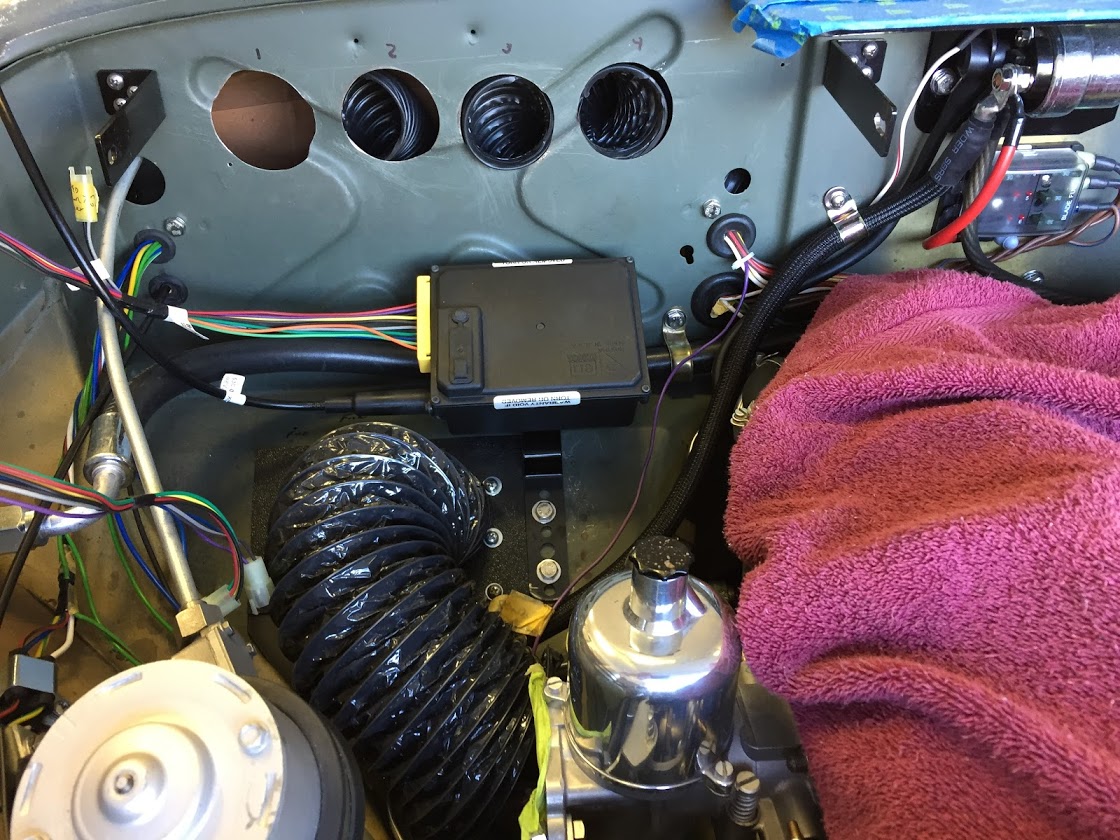
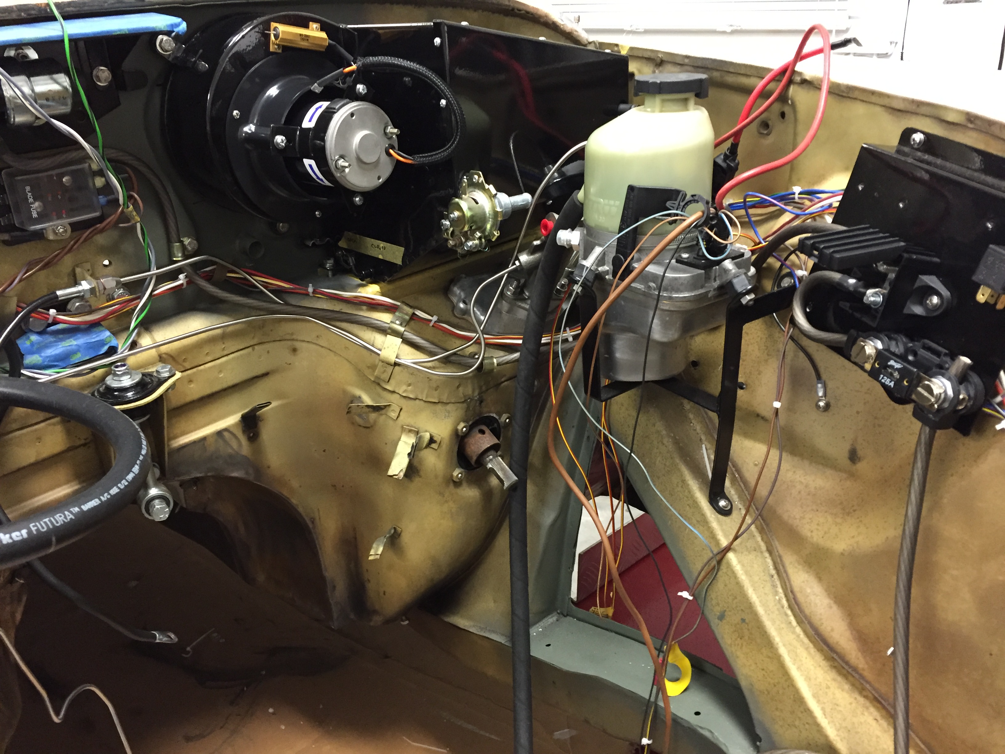
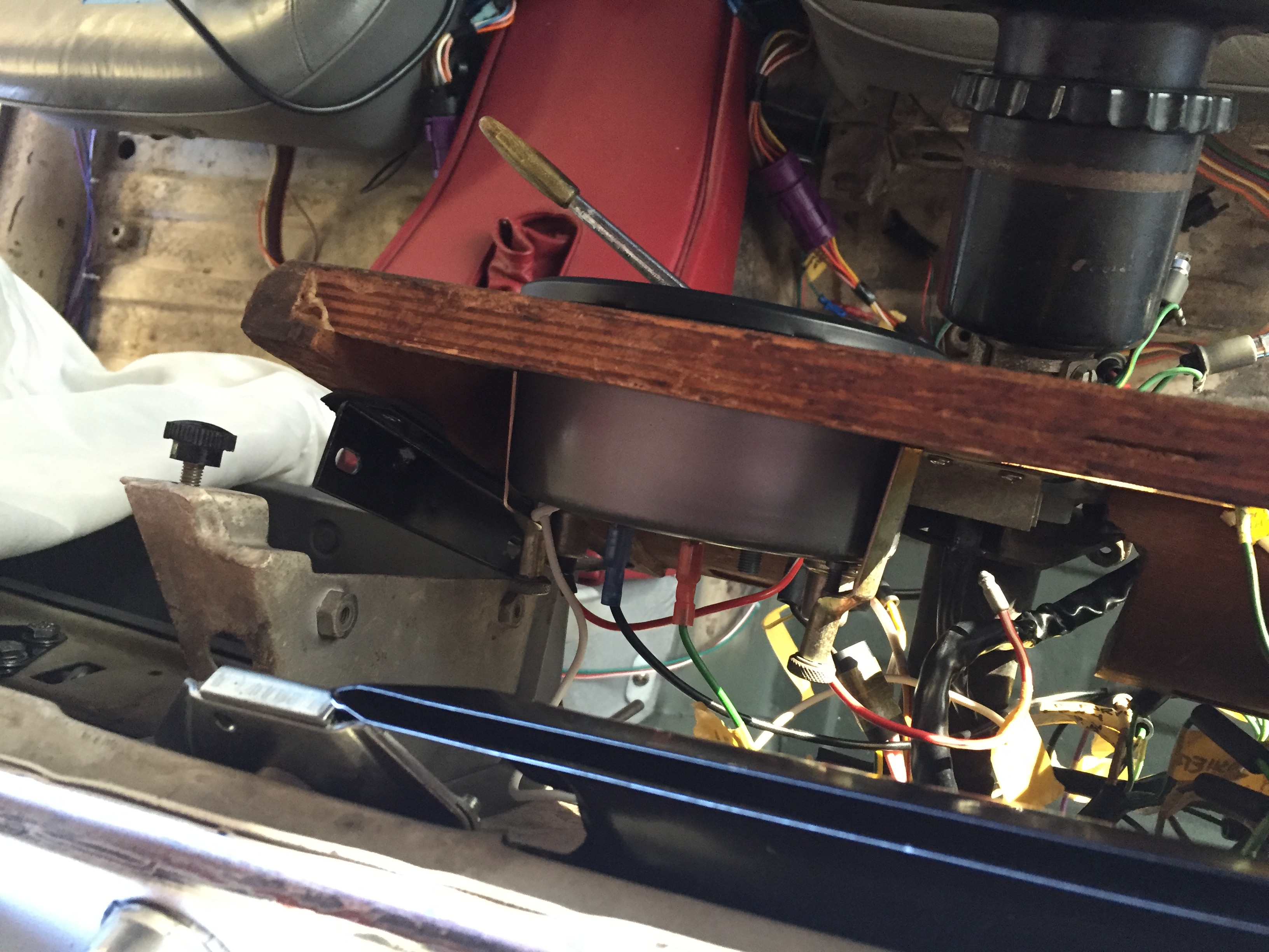
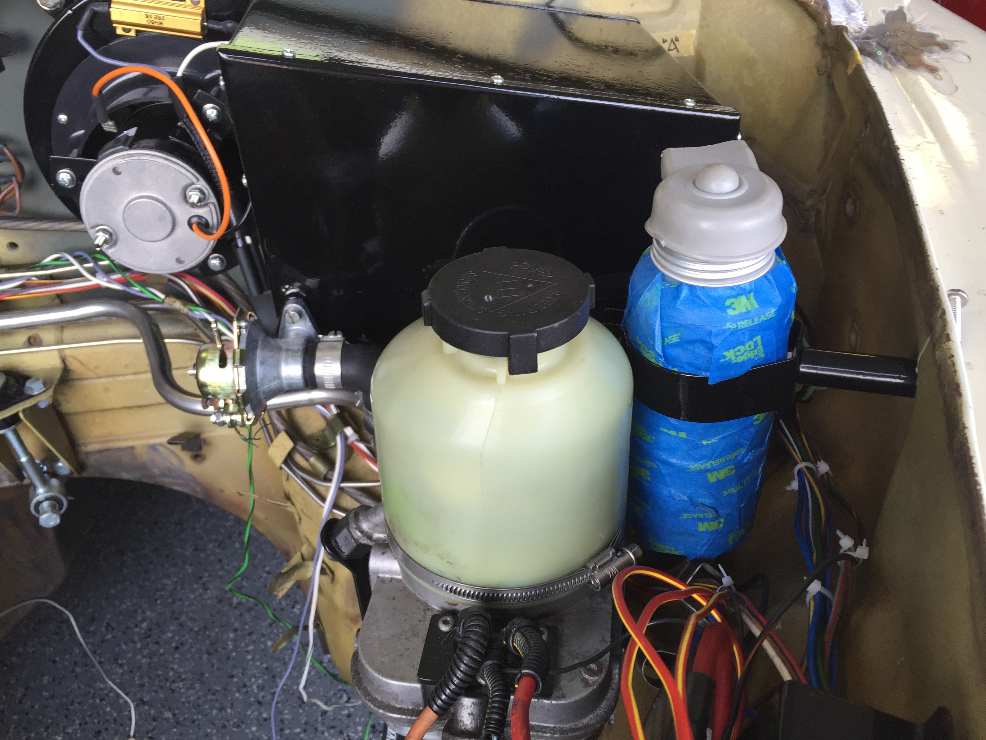
Alan Hendrix of Hendrix Wire Wheel installed the cruise control on Devin William’s car. He chose to mount the canister along the LH frame rail and then routed the cable up into the engine bay. In my case I wanted the canister hidden as much as possible (of course, this means it will be harder to get to if you need to access the canister again!), and I was somewhat restricted as I have mentioned. I ended up removing the curved metal bracket on the canister and used plastic ties to mount the canister to the dash fascia brace to the right of the steering column.
")
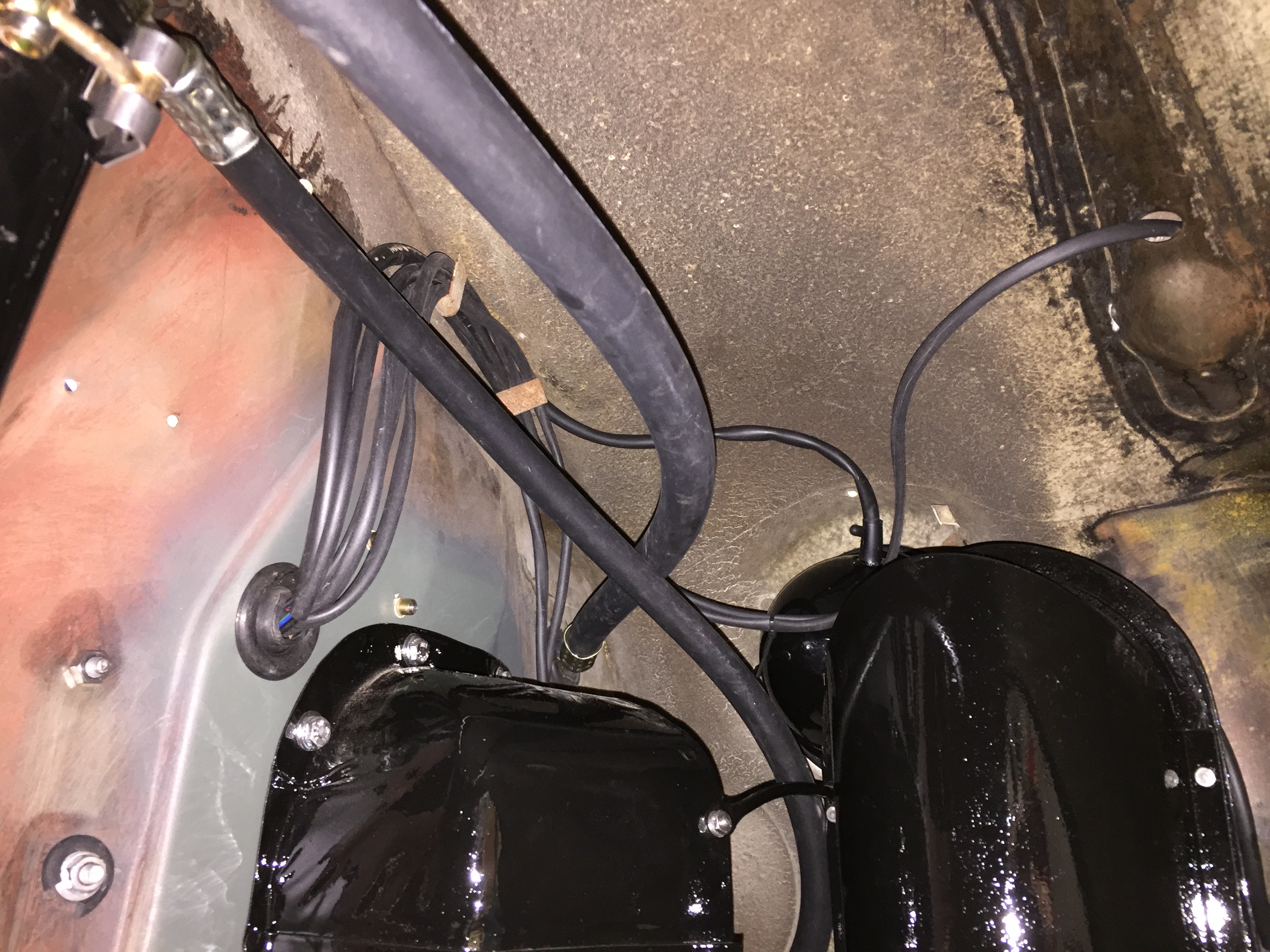
Vacuum Unit Install Image 19
This was easy for me since the front shroud was not on the car at the time, but I could still get to it from under the dash if needed. Pardon the wiring mess in the image above, I had not yet “cleaned-up” the wiring when I took the photo.

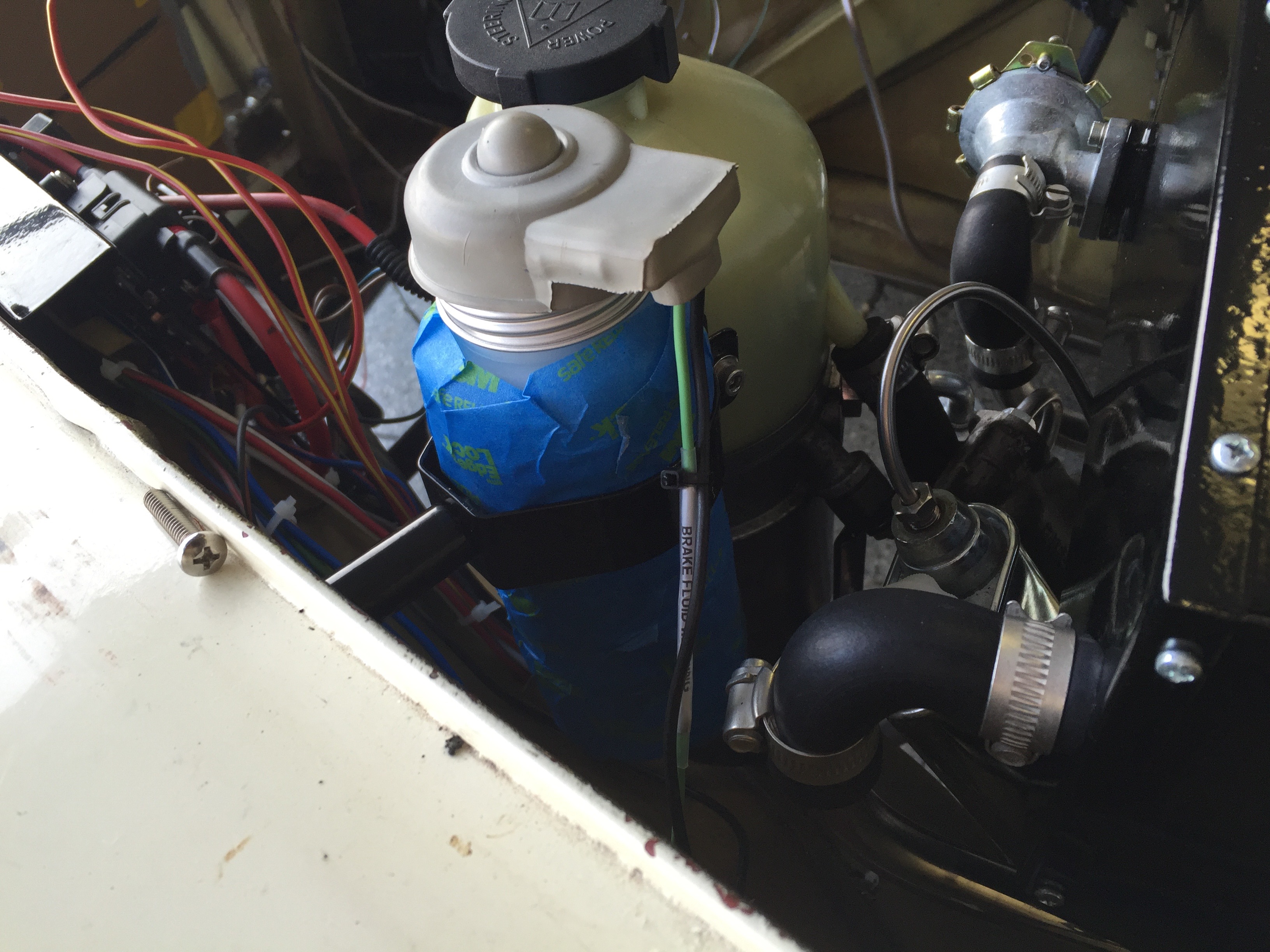
My BT7 Vacuum Unit Install Image 20
In the end, inside the engine bay, inside the cockpit, or along the frame is a matter of personal preference. The instructions emphatically state not to mount the vacuum canister on the engine itself. Each has its advantages and disadvantages. Inside the cockpit means it is probably easier to hide the 10-pin connector and the wiring harness, but it also means that you must route the throttle control cable and the vacuum line from the canister through grommets on the firewall. Inside the cockpit the canister is more easily hidden, but you also can hear the unit working (not objectionable levels to me) since you don’t benefit from getting the unit on the other side of the firewall. You just need to experiment. Let me know if you come up with another location and send me an image and I will include it in this little write-up!
Once the location of the canister is determined, the vacuum line needs to be installed. In their Healey Marque article, Dick Lunney and John Jones described using copper tubing for the vacuum line rather than the rubber hose included in the kit. Whatever you choose to use, the tubing or hose needs to get connected to the intake manifold. Depending upon what you have connected to the manifold already (brake servo, pcv valve and etc.) will determine whether you can use a fitting already available on the manifold, whether you will us a “T” splitter provided in the kit, to take advantage of a vacuum line already in place, or whether you might even drill and tap another hole in the manifold for a fitting as Dick and John did.
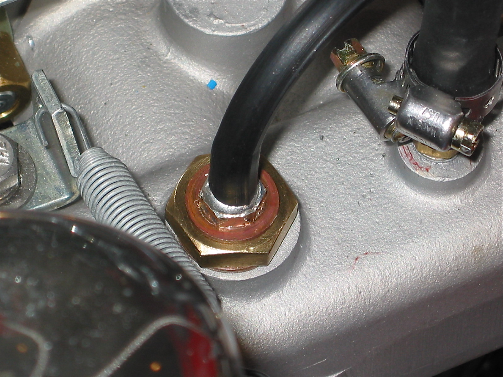
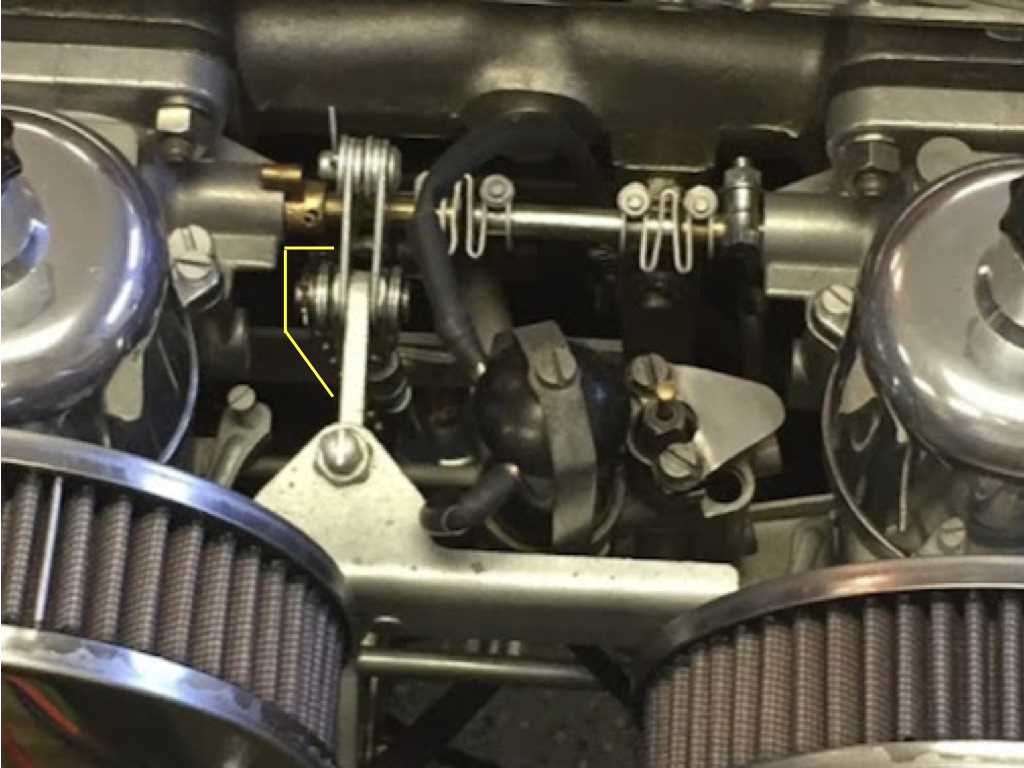
In my case, I am using the small original fitting on the manifold for a pcv valve, the vacuum line to the distributor is routed from the rear carb (I am using HD8 BJ8 carbs on my BT7), so that left the original large blanking plug (7/8” I believe) on the manifold to be used. I drilled a hole through the center of the plug. Tapped it, installed a radiator drain valve I had laying around, soldered the fitting to seal it and presto I had a nice little connector for my cruise control canister. I used what I had, I am sure you can come up with something that will work equally well! These are images of the fitting and the installation of the hose:

Homemade Vacuum Fitting Image 21

Cruise Control Vacuum Fitting Image 22
By the way, the stainless cable in the right photo is my throttle cable routed from the accelerator pedal lever – not to be confused with the throttle cable for the cruise control assembly.
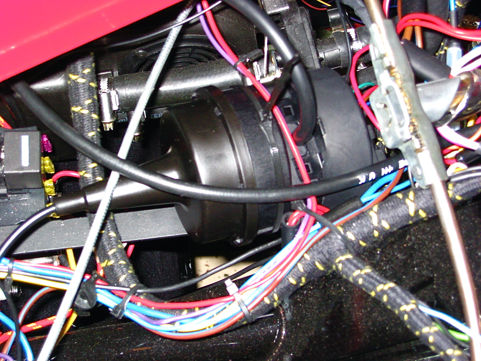
So far we have installed the magnet and sensor, the cruise control control module and the vacuum canister with its vacuum line. It is now time to turn to the wiring for the cruise mechanism.
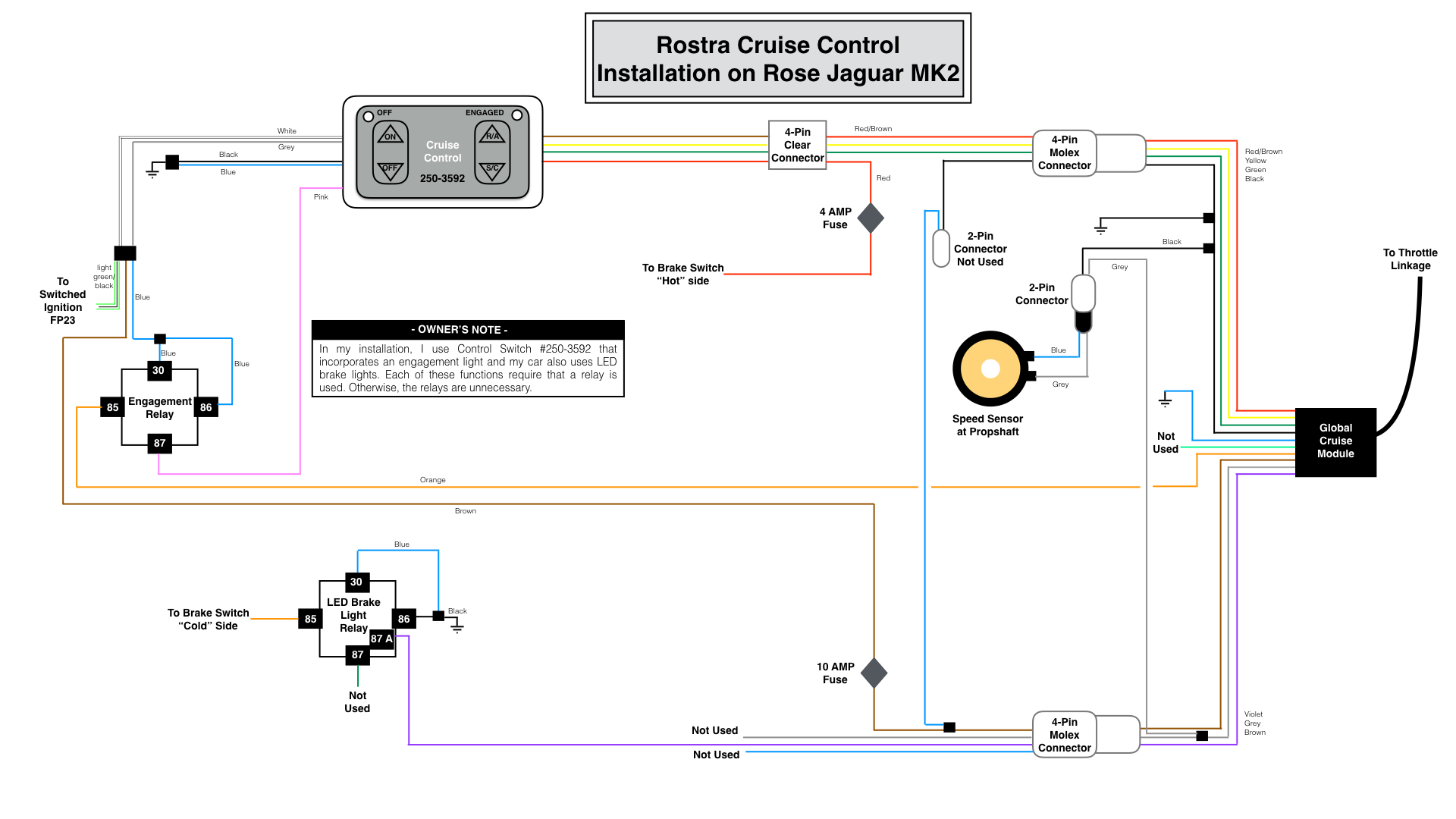
Cruise Control Wiring
Caution: Follow the wiring instructions included with the cruise control kit! I have simply provided a guide that reflects how I wired my car, but remember yours may be different. My car has been converted to negative ground.
Turn “off” the battery switch in the boot or disconnect the battery before undertaking the wiring to avoid the potential of unpleasant results!
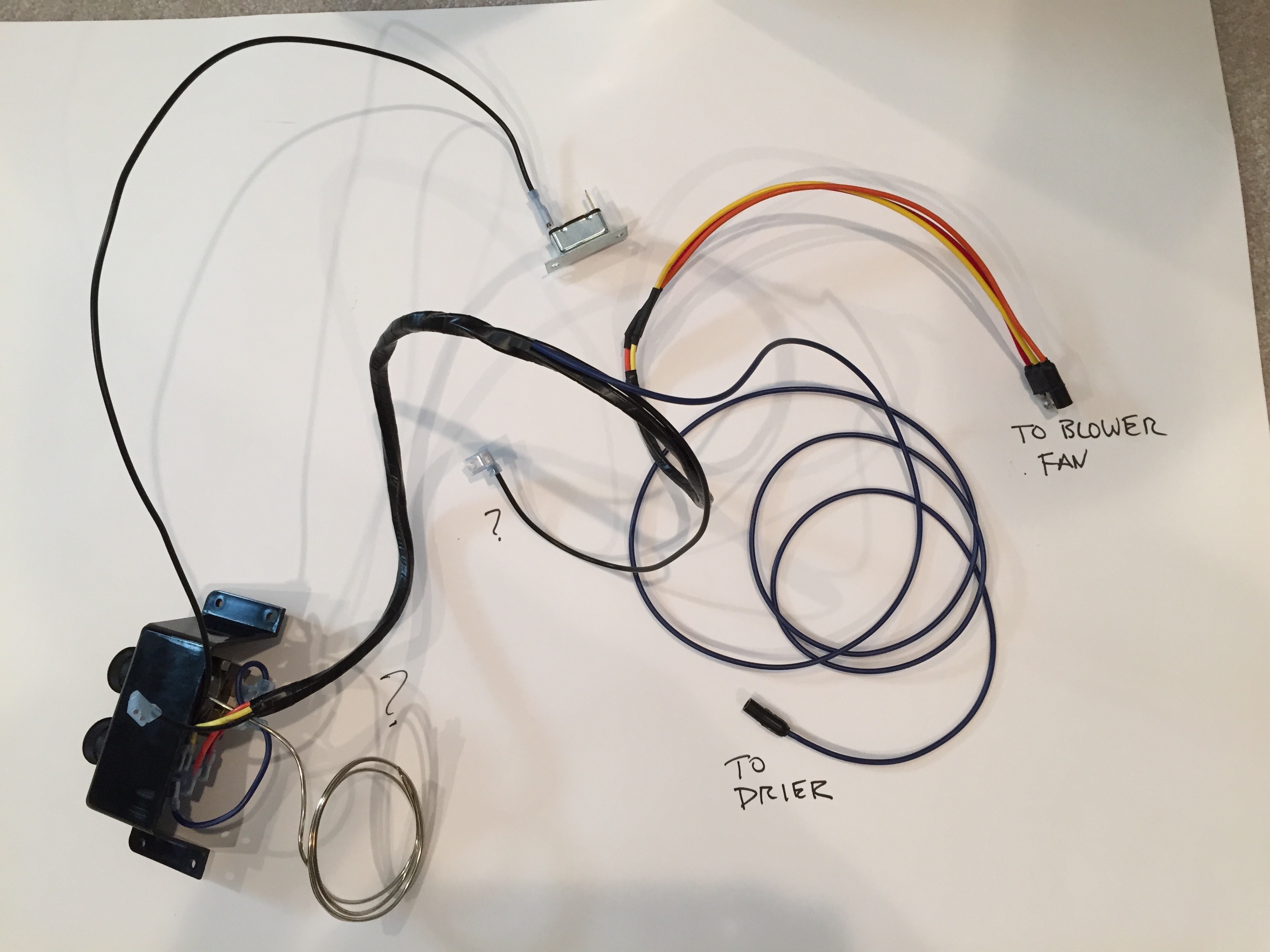
There are a number of wires to connect for the cruise control, but the task is really fairly easy. As typical of most Healey projects, patience is required. I will proceed with the wiring by source location and color. Before actually connecting any wires, I advise figuring out what your routing will be. The harness has a generous length of wire, but you do need to figure out the path of each.
The BT7 gearbox cover is in two parts, the cover itself and the gearbox cover extension between the cover and the firewall. The speedometer cable is routed between the firewall and the cover extension. I decided to run most of my wiring immediately next to the speedometer cable, behind the gearbox extension and to route the wires along the gearbox. In this manner, the wiring is hidden from view. The down side is to access the wiring you must remove the gearbox cover or approach the wiring from under the vehicle. Others have routed the wiring under the carpet. Of course, if you mount the cruise control module on the dash then you will have an entirely different wiring plan. Therefore, again, you will need to map out your wiring plan in advance.
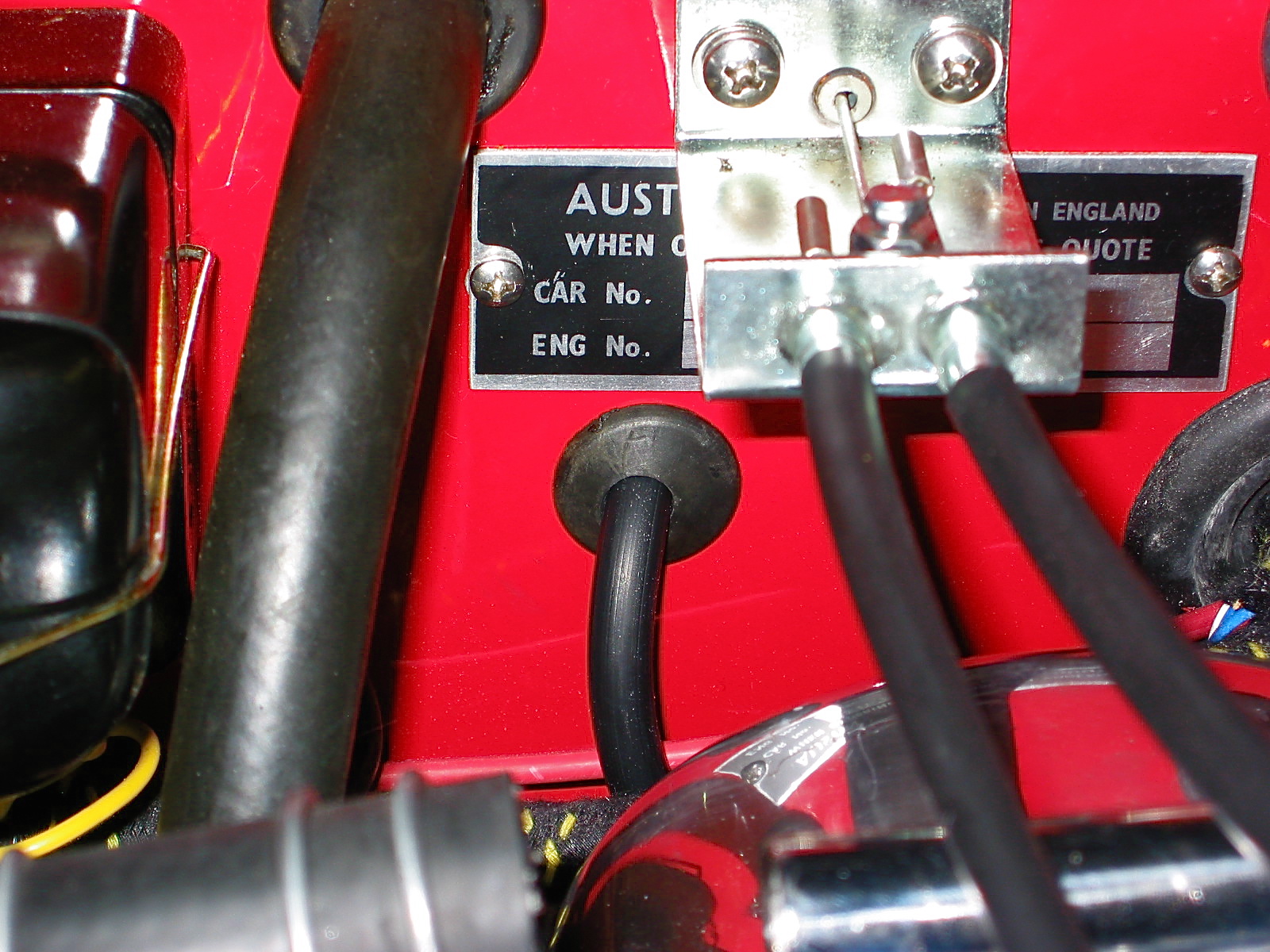
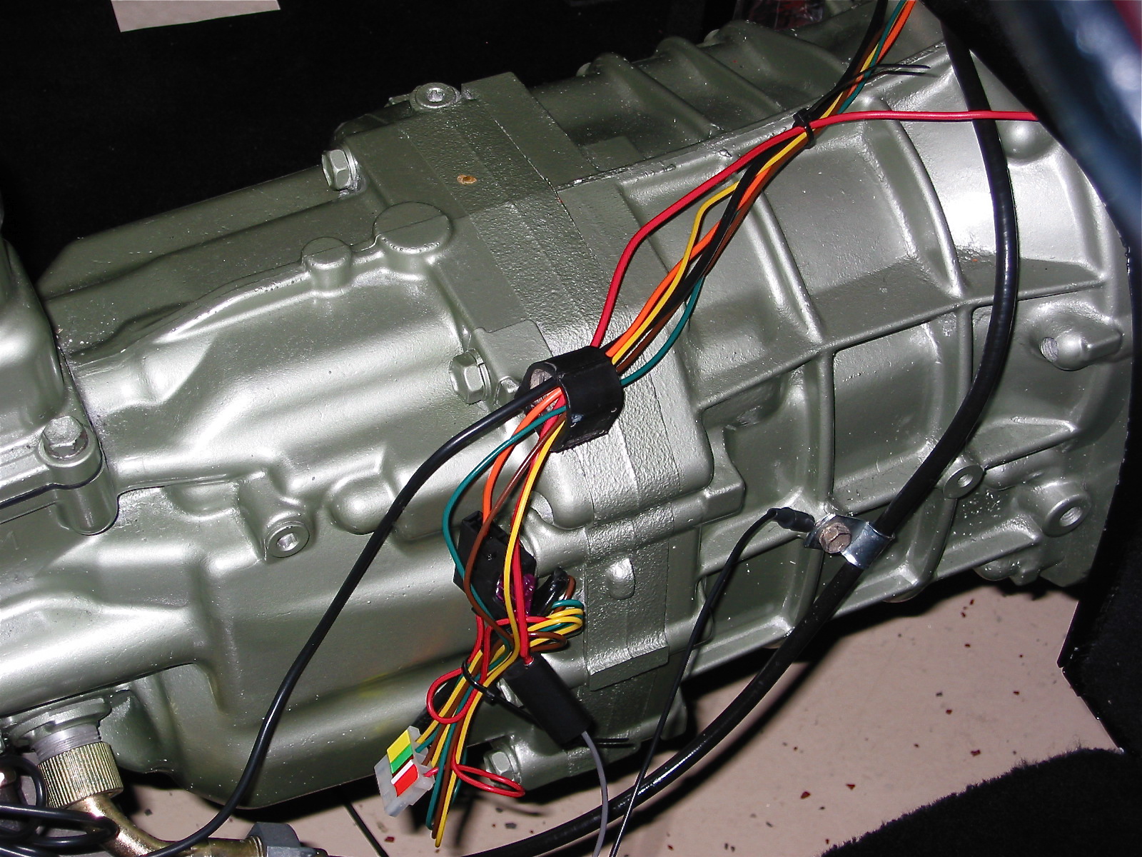
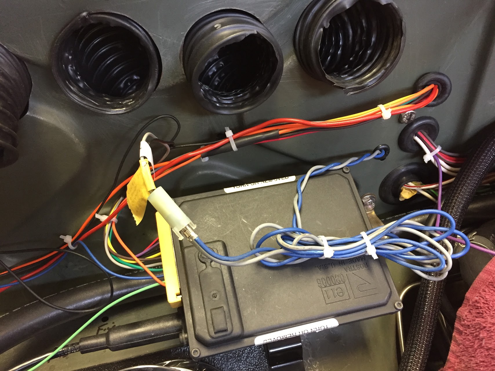
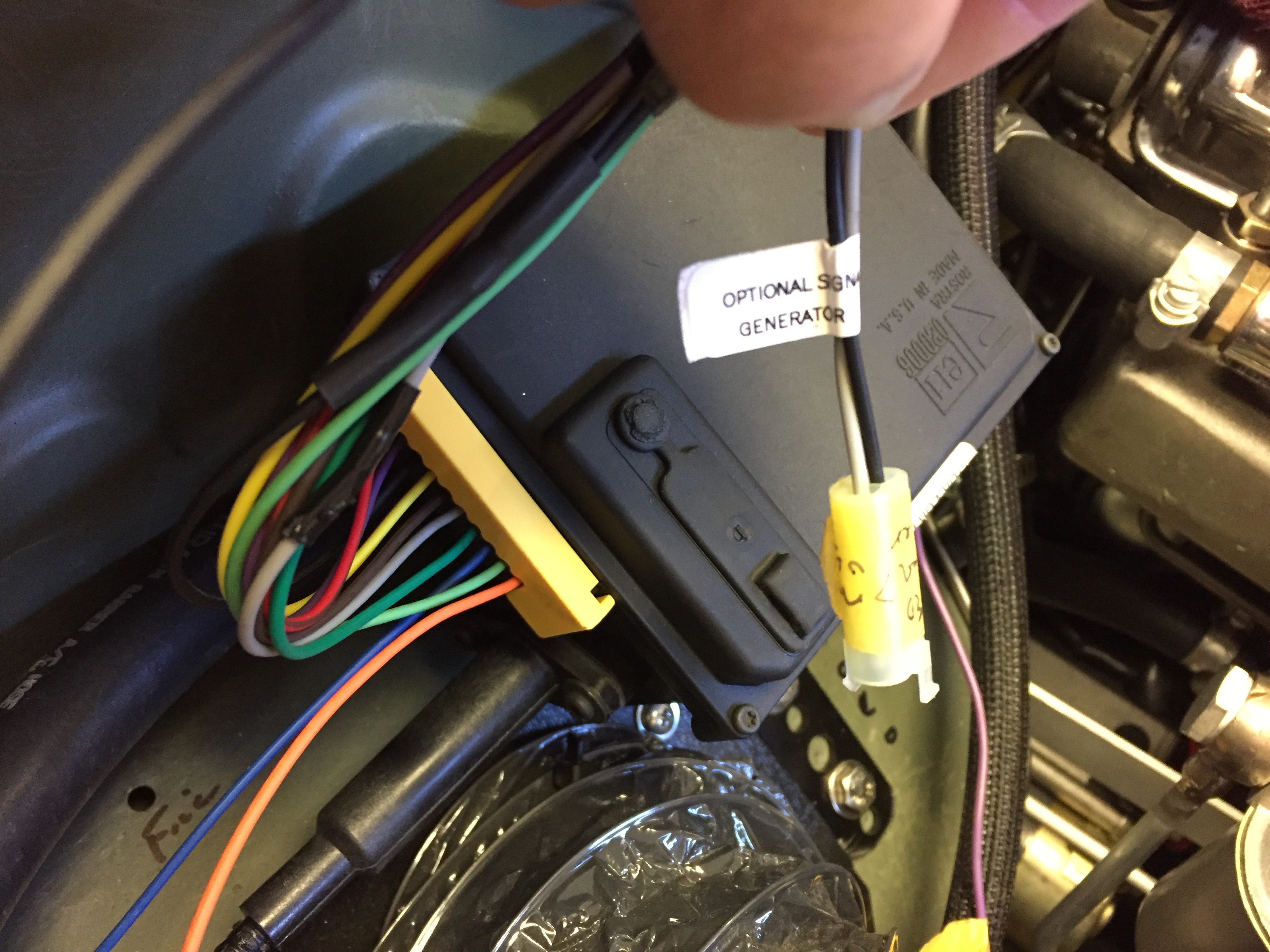
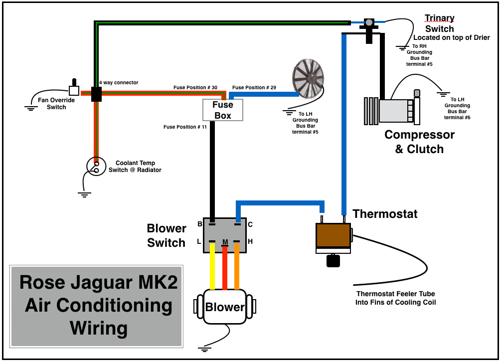
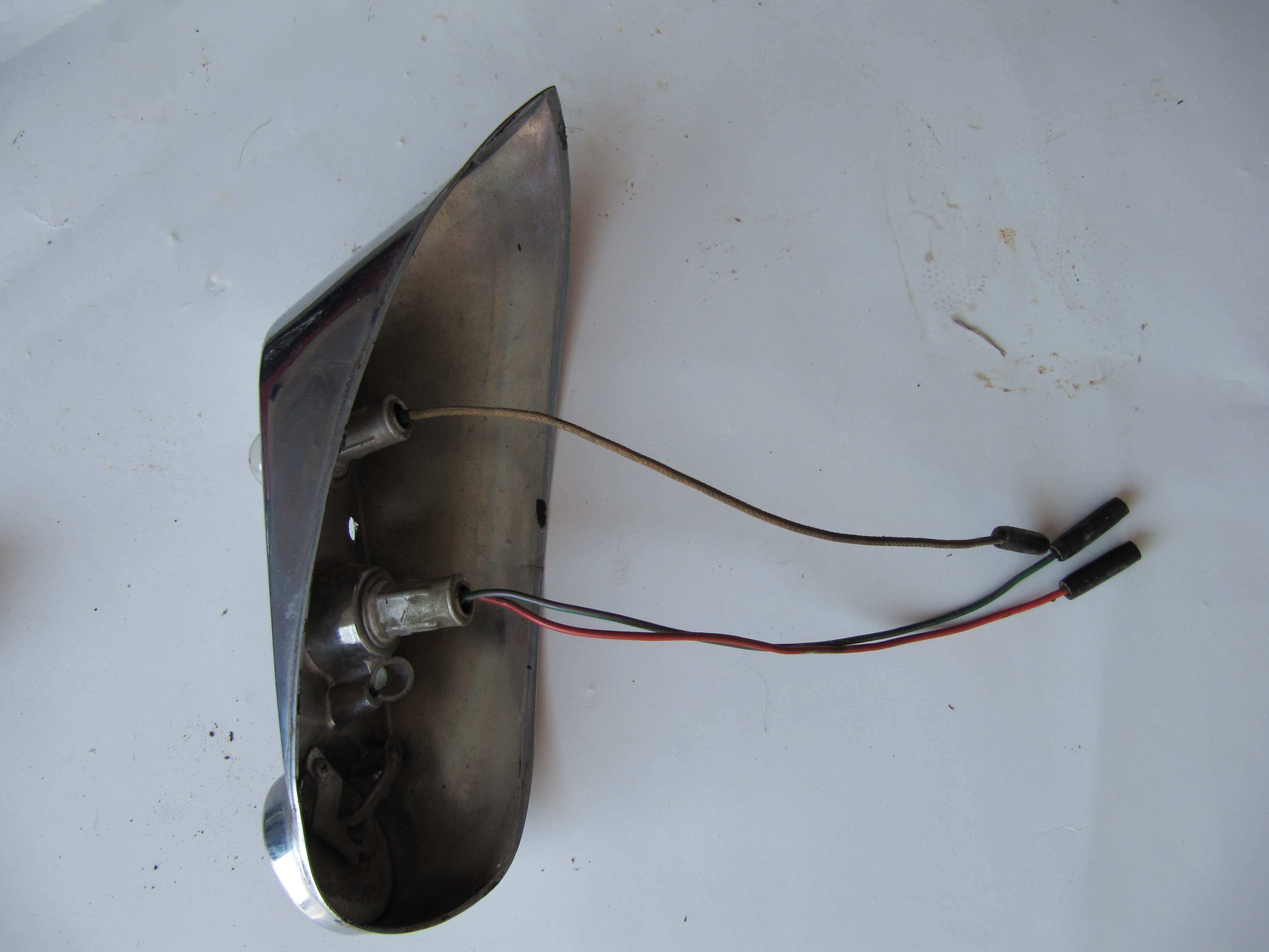
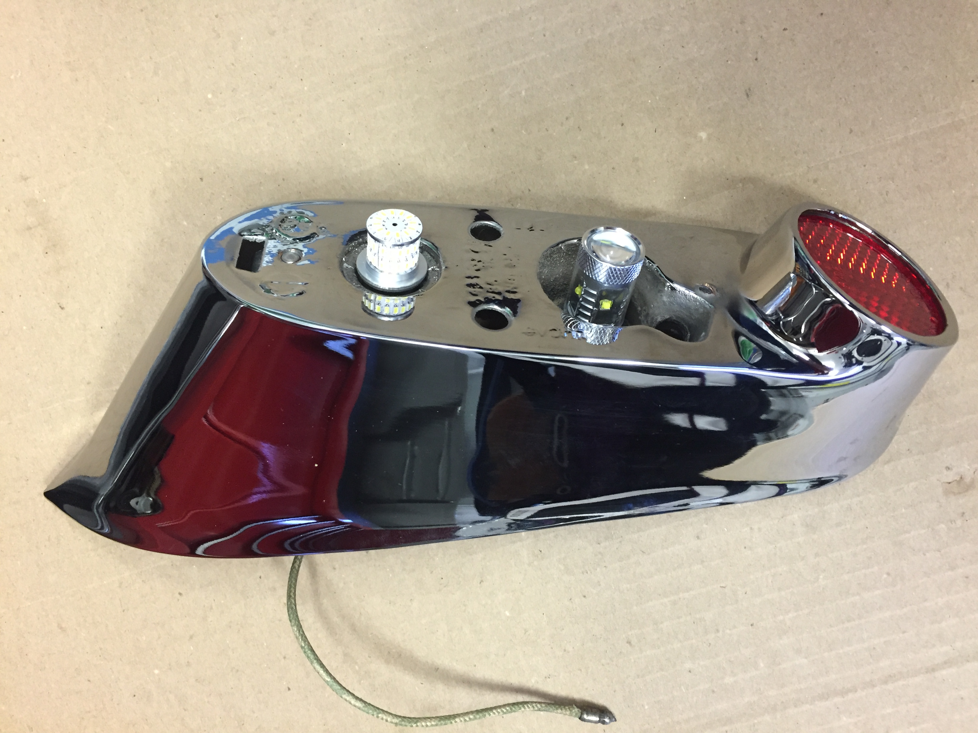
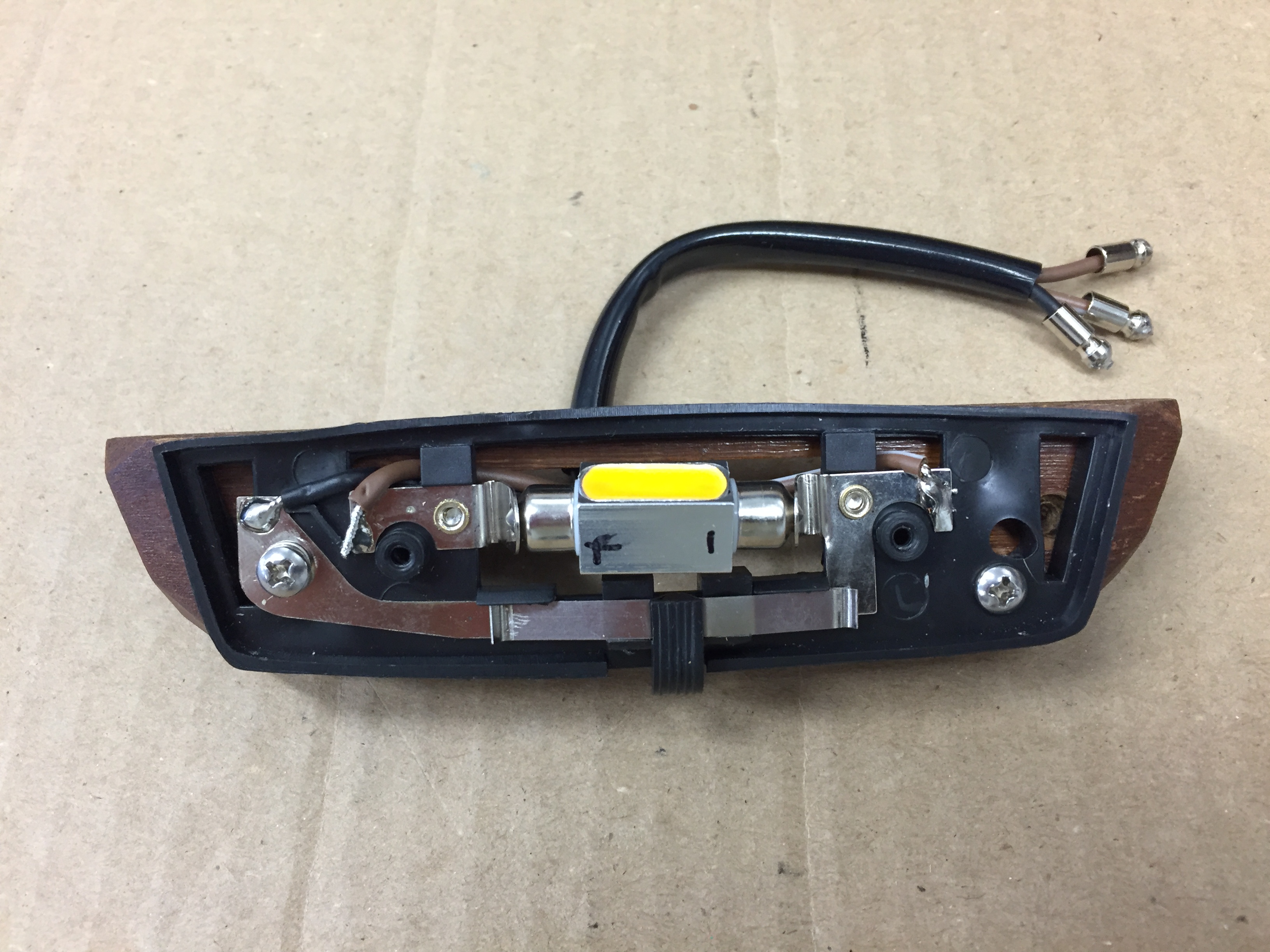
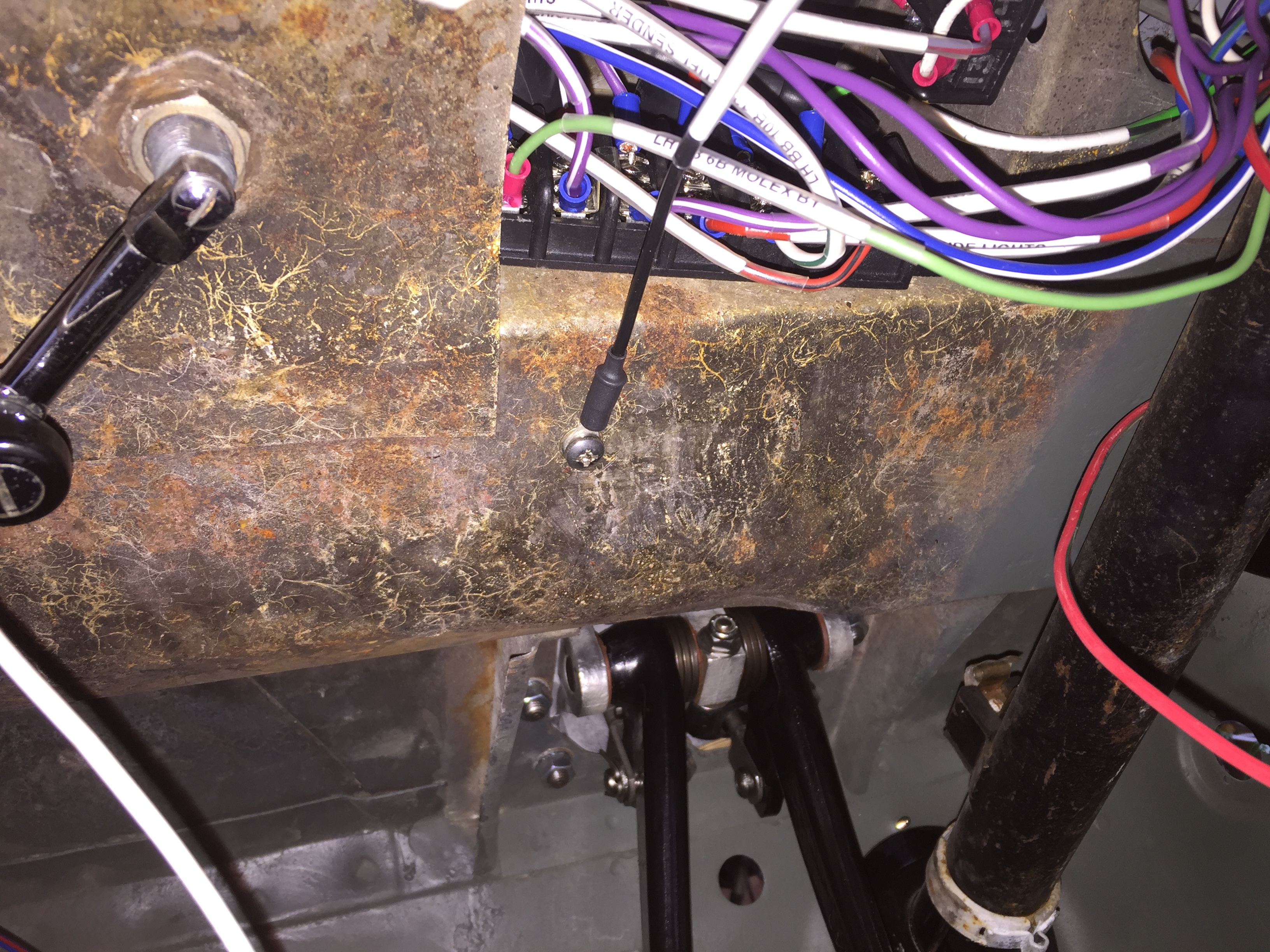
This is an image of the wiring once connected as routed on my car. I left the wiring loose for the photo so the various color wires could be seen. I then encased the wiring in a black plastic tube (provided in kit) to give a neater installation. Remember, I am using a Toyota 5-speed gearbox.

Cruise Wiring Along Gearbox Image 23
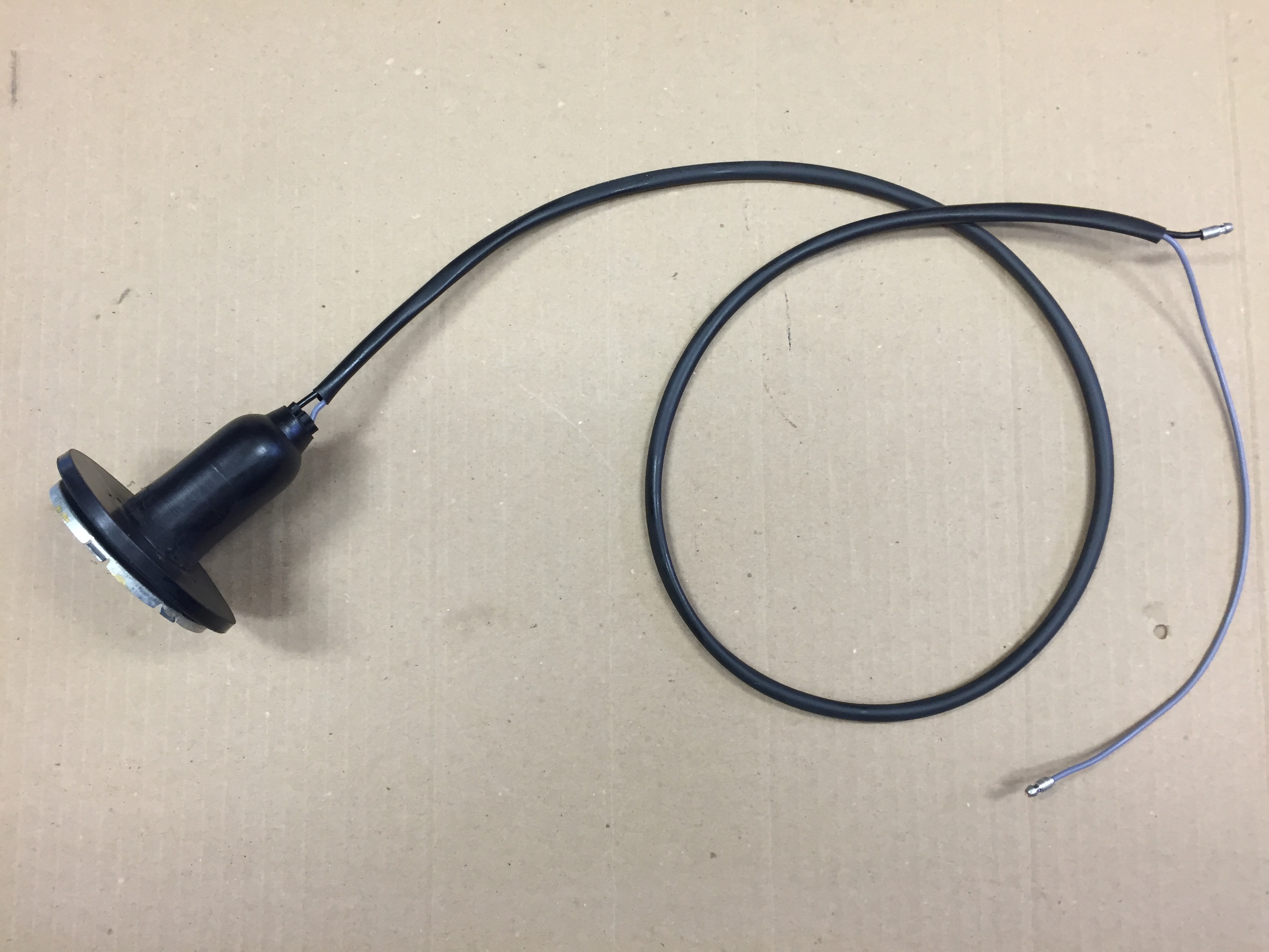
- Black wire with eyelet terminal from vacuum canister to an earth (ground) point. I used a screw and nut on the interior side of the firewall.
- Blue wire to the negative terminal on the coil. For me, this was a fairly long run and I routed the wire through the clips on the firewall brace that hold the original wiring harness wires to the brake switch and the ignition.
- Grey and black wires encased in heat shrink tubing are connected to the magnet sensor in the tunnel next to the propshaft. It doesn’t matter to which terminal the wires are connected.
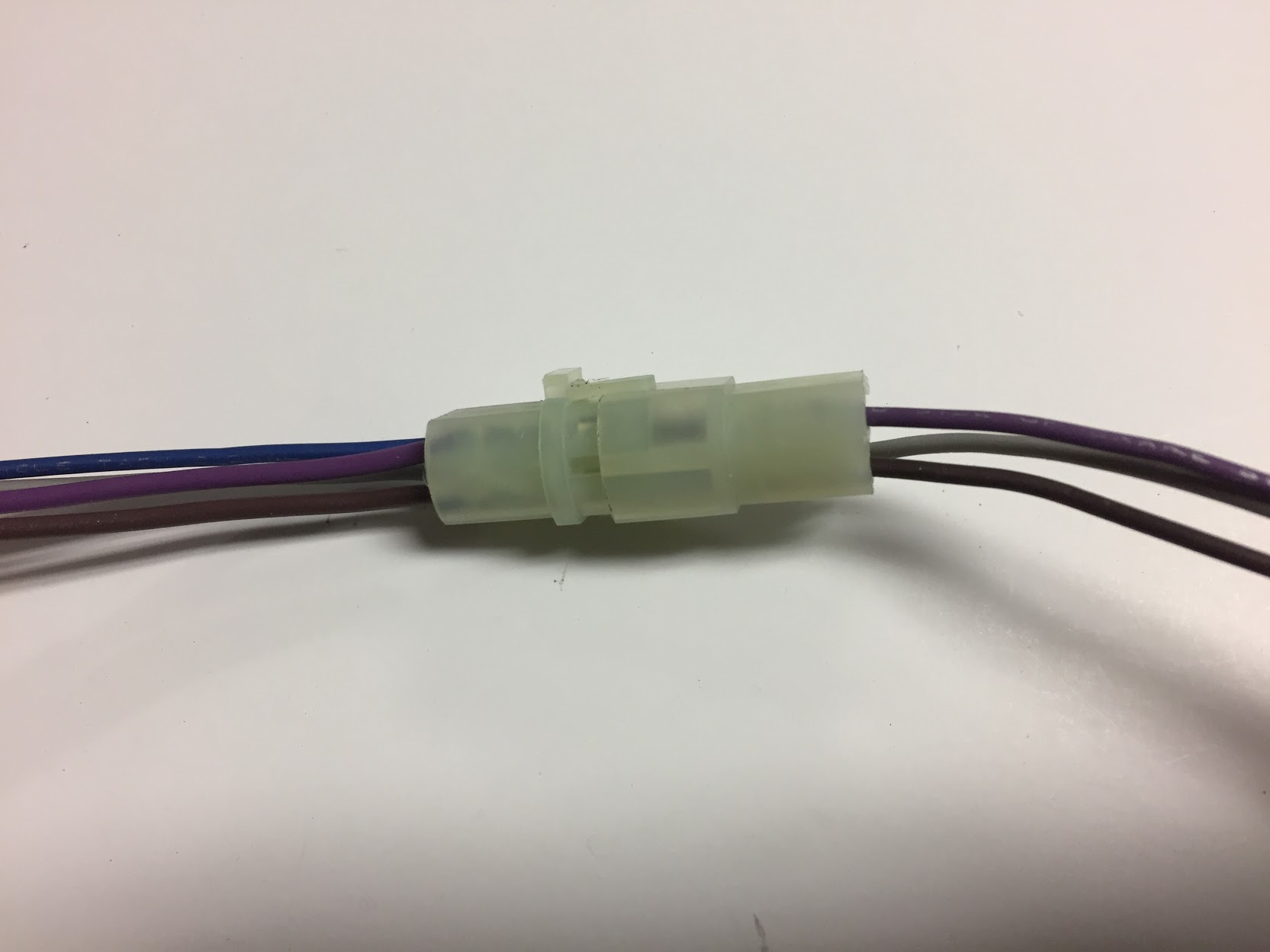
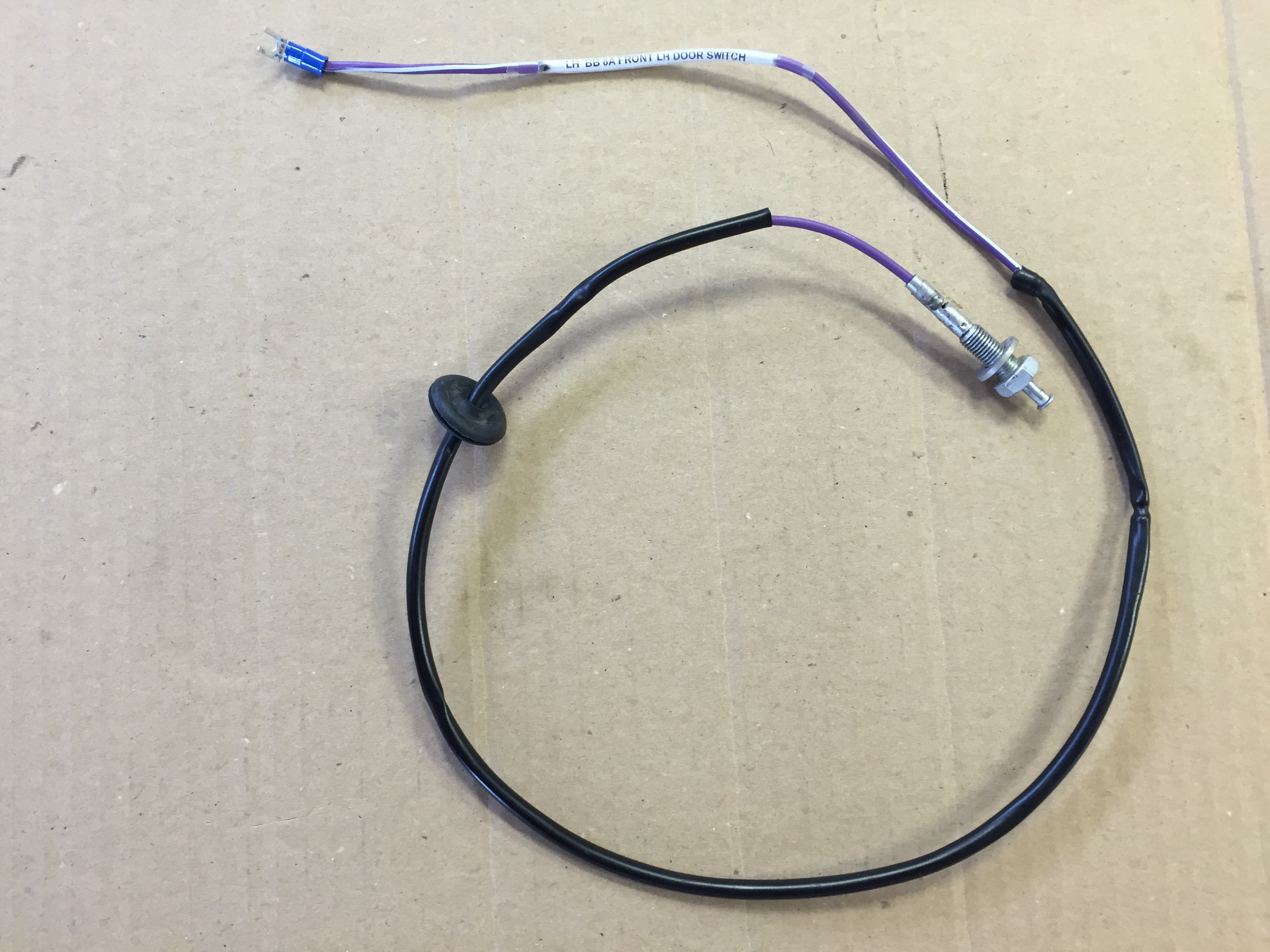
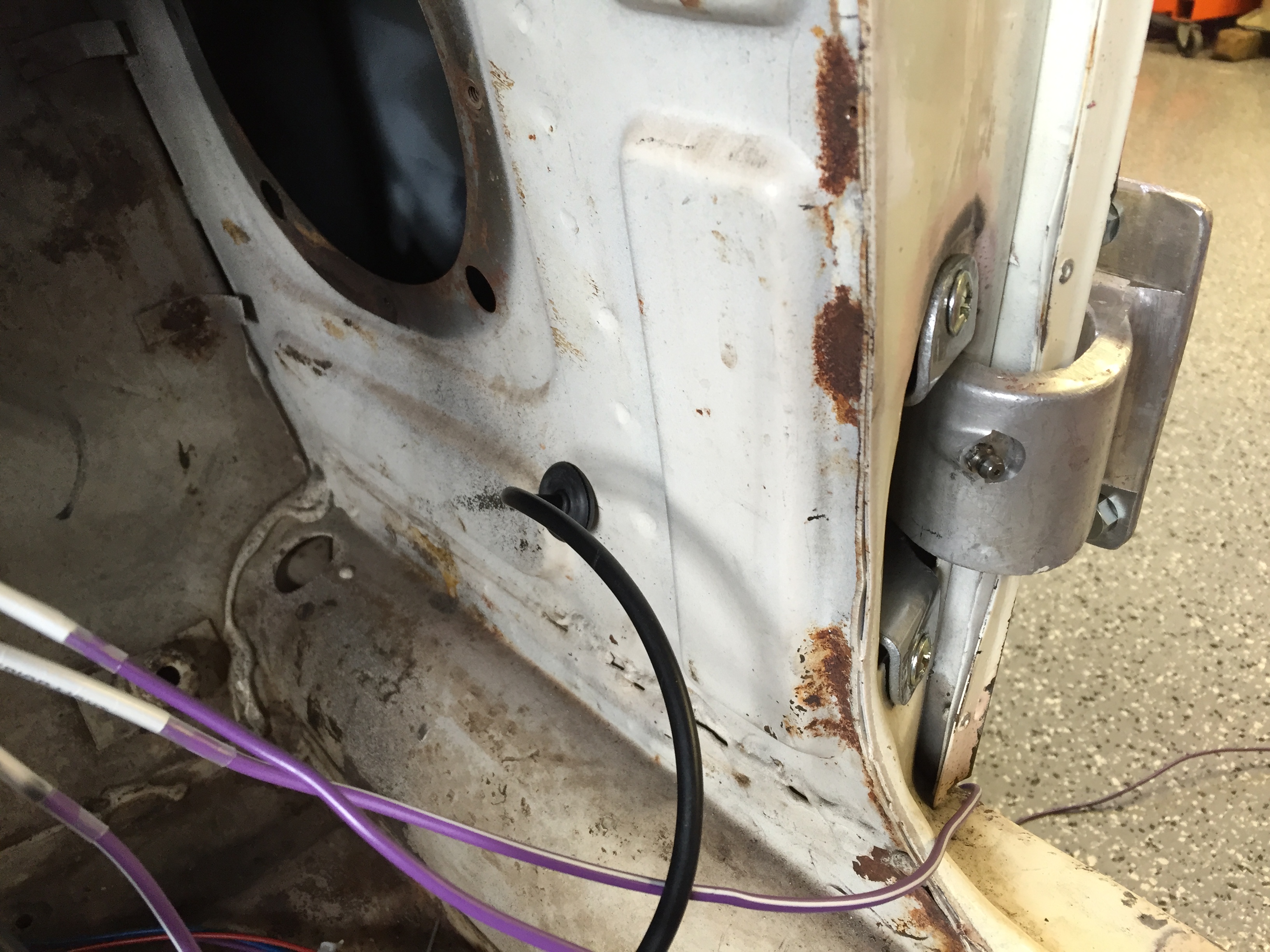
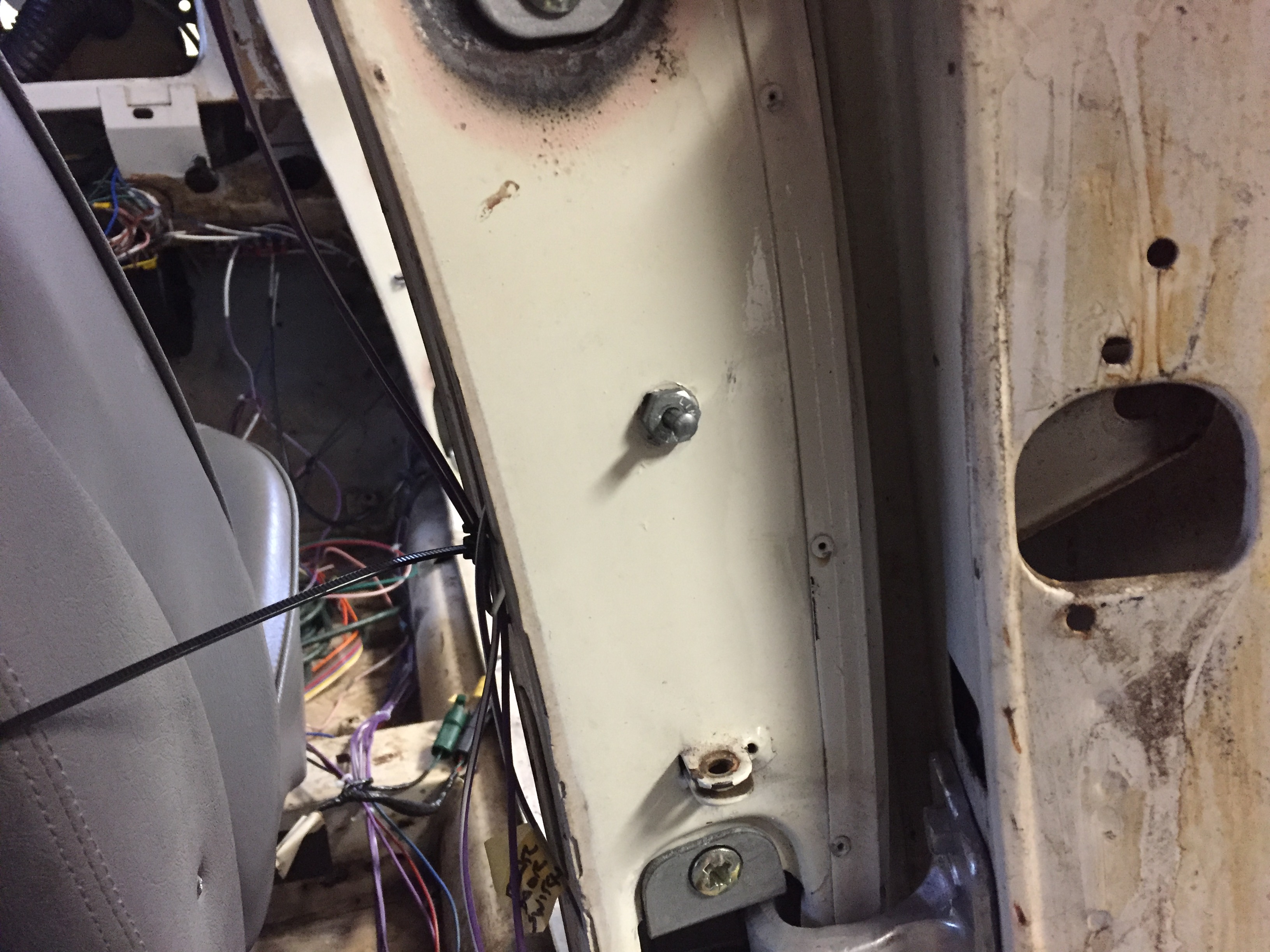
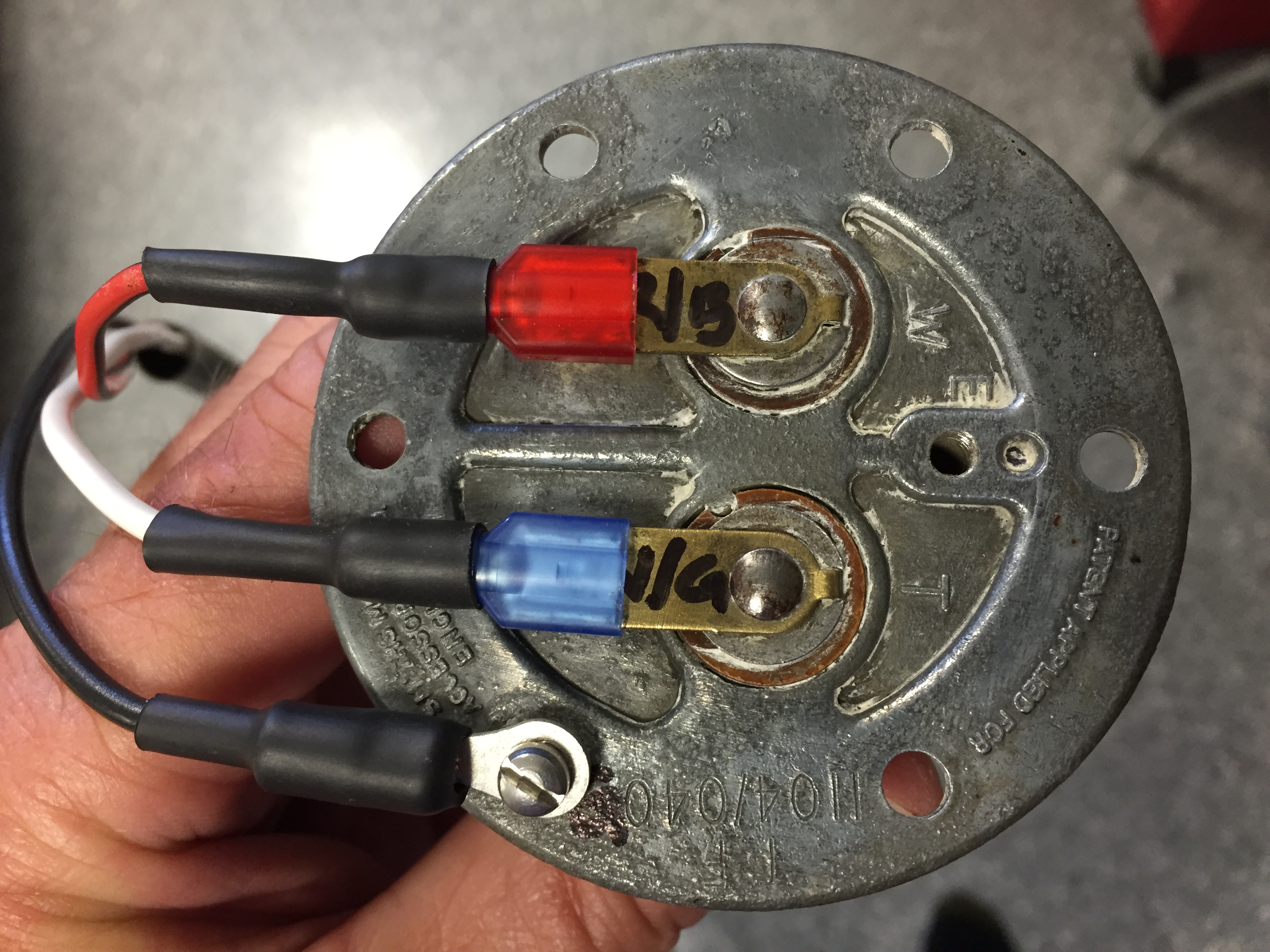
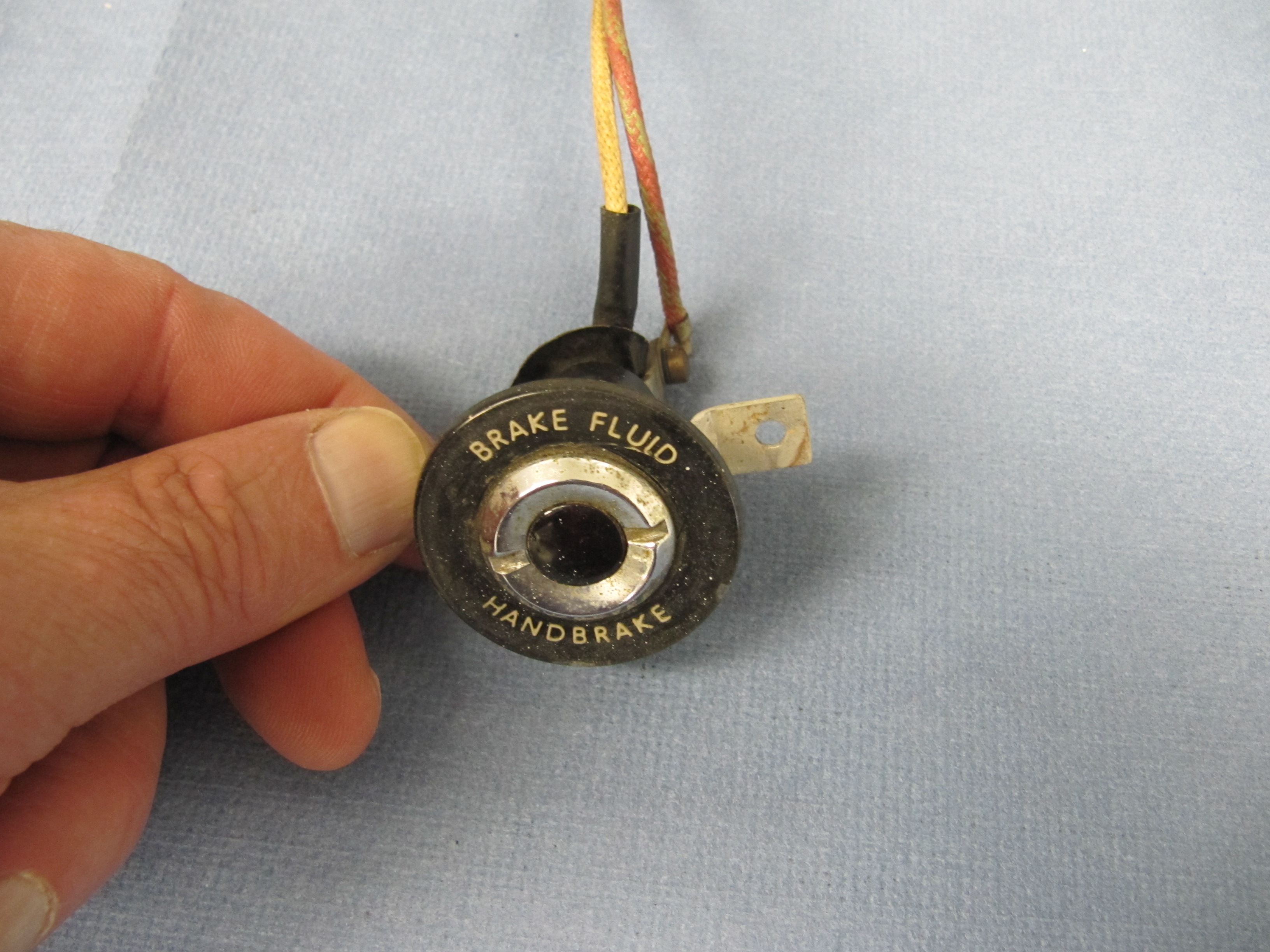
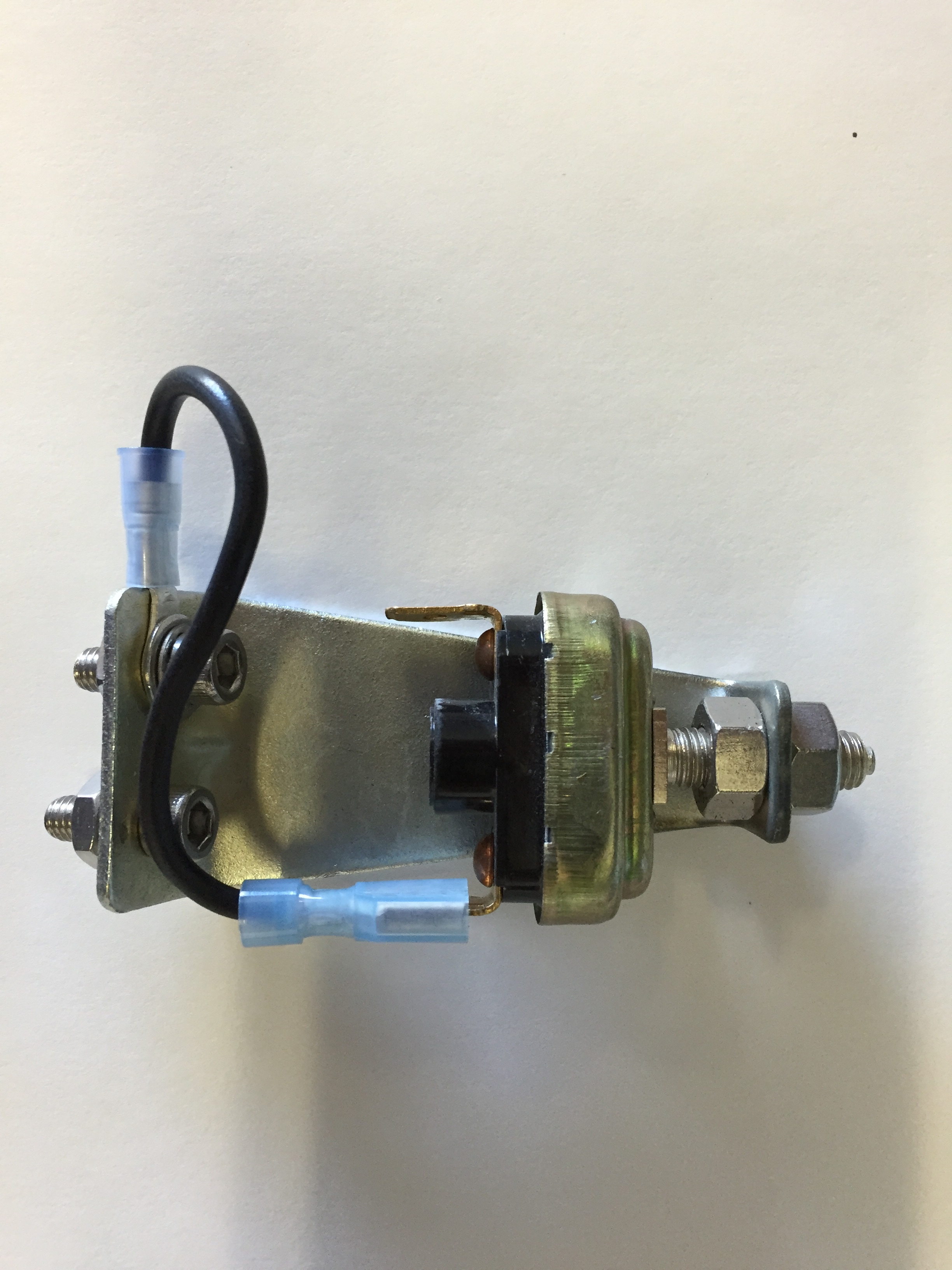
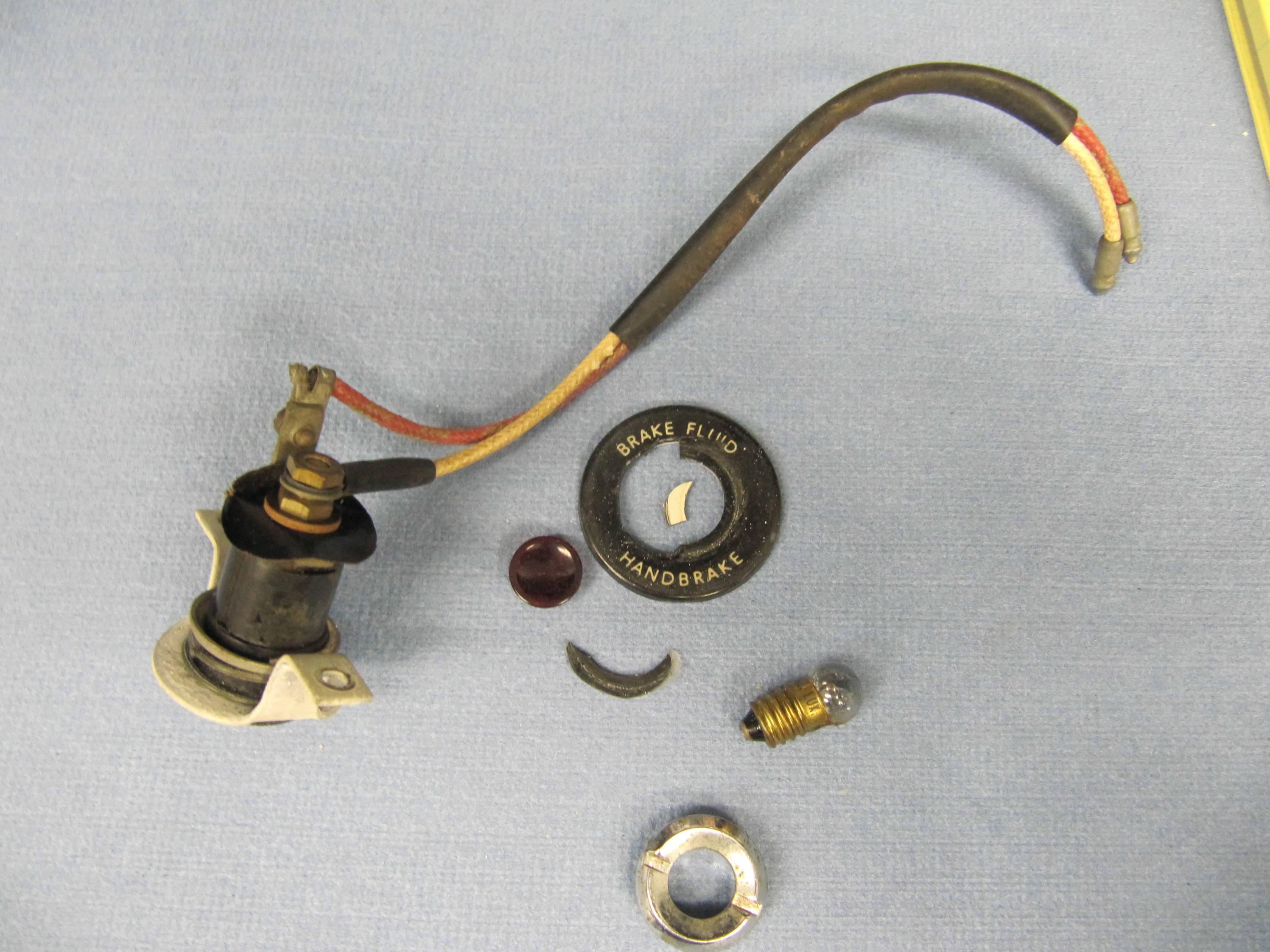
- Purple wire to the brake light switch wire that is hot when the brake pedal is depressed. In my case, for the BT7 that is a green wire with a purple stripe. I use a Watson’s mechanical brake switch rather than the original hydraulic pressure switch, so my wiring actually connected close to the fuse block on the firewall. My wires were routed through existing rubber grommets. Again, your wire routing will depend upon the model of your car and whether it is as original or modified.
- Red wire to the constant positive 12 volt battery source to the brake light switch. This is the wire that remains hot whether or not the brake pedal is depressed. In my case that is a solid light green wire.
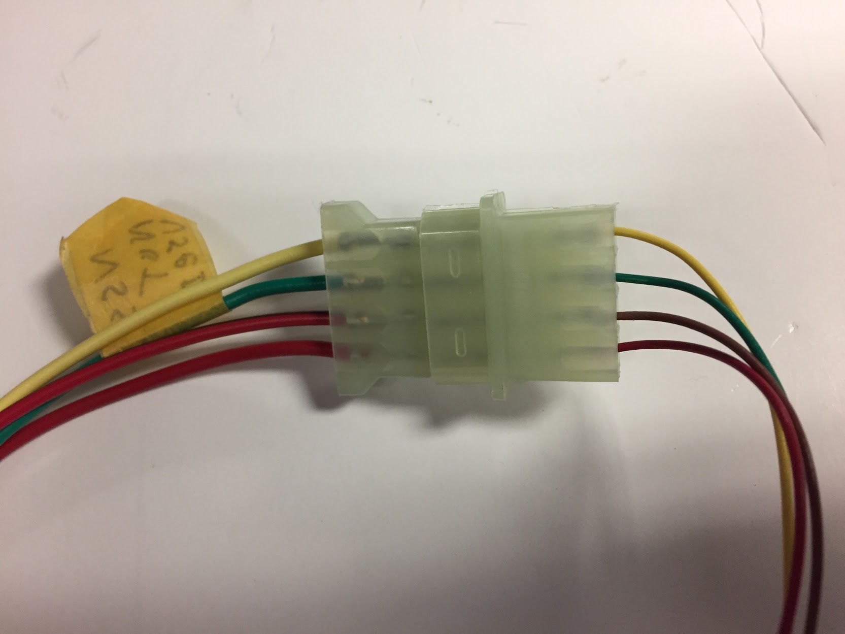
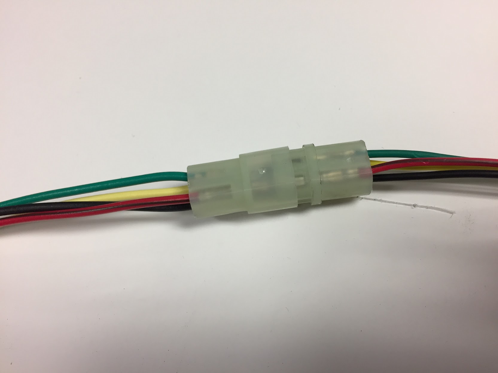
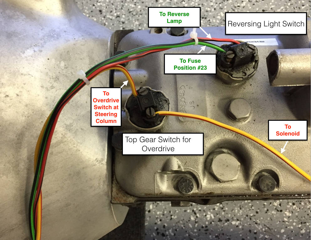
- Orange fused wire with switch connector needs to be loaded with the brown, green and yellow wires from the main harness into the 4 pin connector. Both ends of the plastic connector are color coded to match the wires. Each wire should be pressed in until you hear an audible “click.” After the connectors are loaded then route your wires and press the pieces of the 4-pin connector together (the other side of the 4-pin connector originates with the cruise control module). In my case that was behind the gearbox extension and along the top of the gearbox. The orange wire needs to be connected to a source with positive 12 volts after the ignition switch is turned to “on.” Just as an aside, I later inserted a four-way bullet connector in the orange wire, after the in-line fuse, to allow for the addition of a grey wire to the gearbox “back-up” switch terminal so that I would have “switched” power to the reverse terminal.
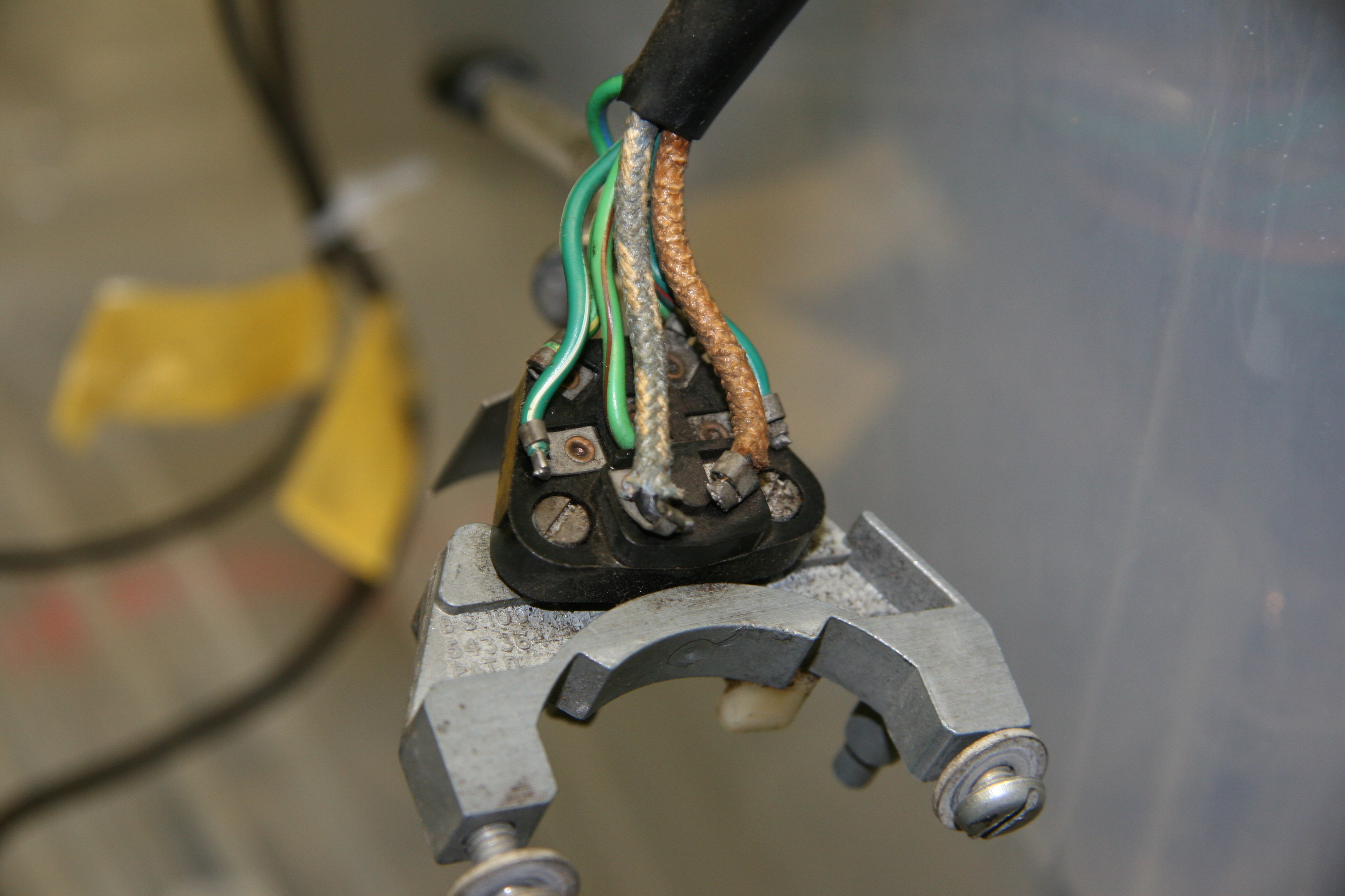
- Grey wire from control module to the light switch on the dash fascia. The terminal that is hot when the parking lights are turned “on.” This connection provides illumination for the control module.
- Black wire from the control module to an earth (ground) connection. In my case a screw on the side of the gearbox.
- Yellow wire from the control module is routed through the molex connector to the yellow wire to the servo.
- Green wire from the control module is routed through the molex connector to the green wire to the servo.
Trouble shooting: The instruction booklet provides a test sequence for the wiring if for some reason your unit is not functioning as it should.
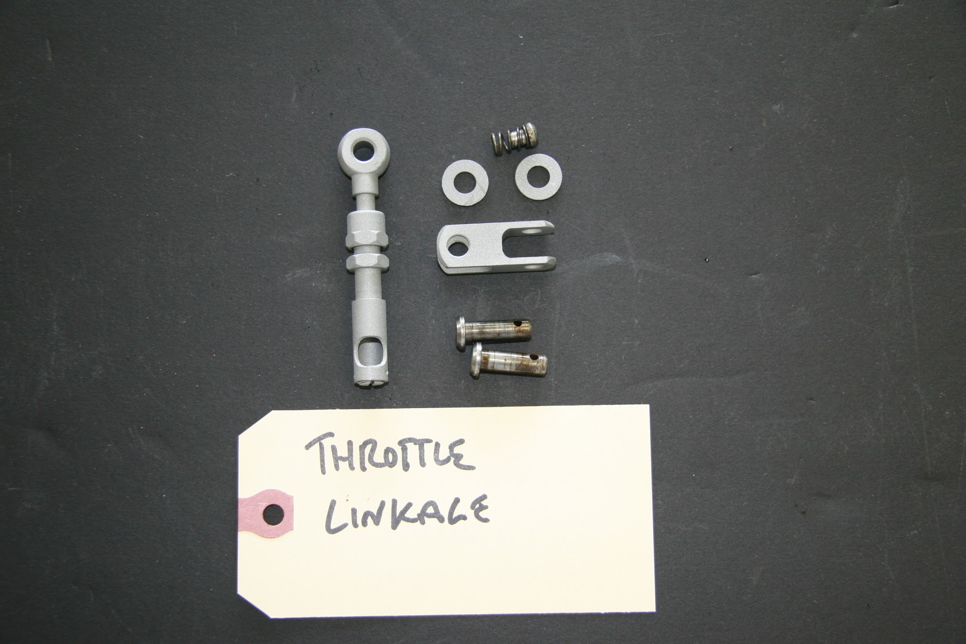
Throttle Control Linkage.
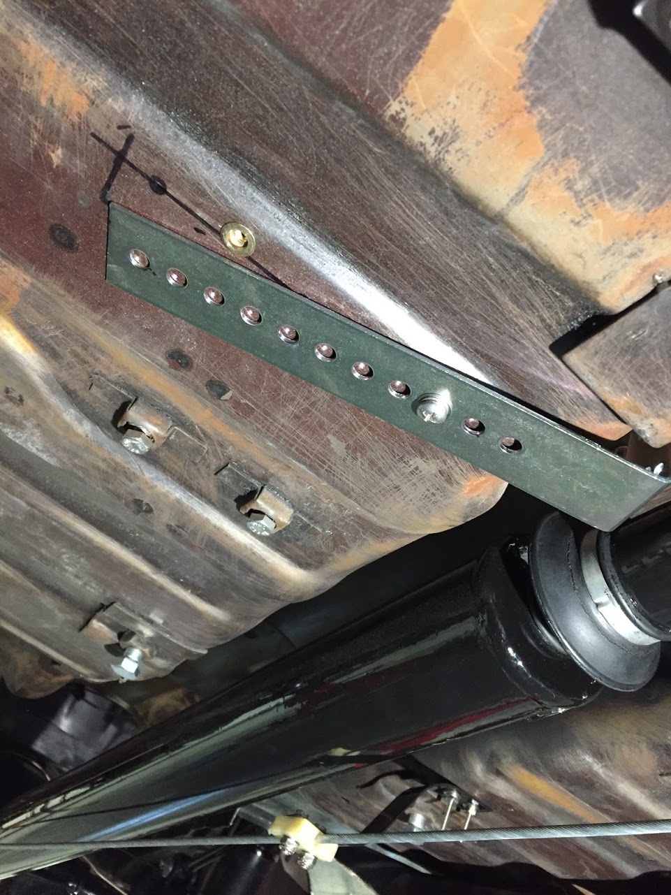
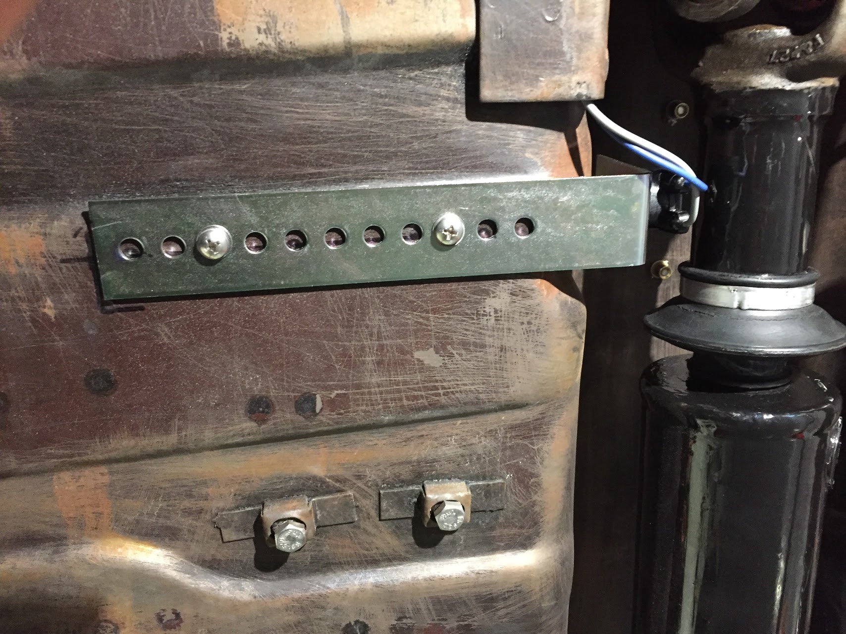
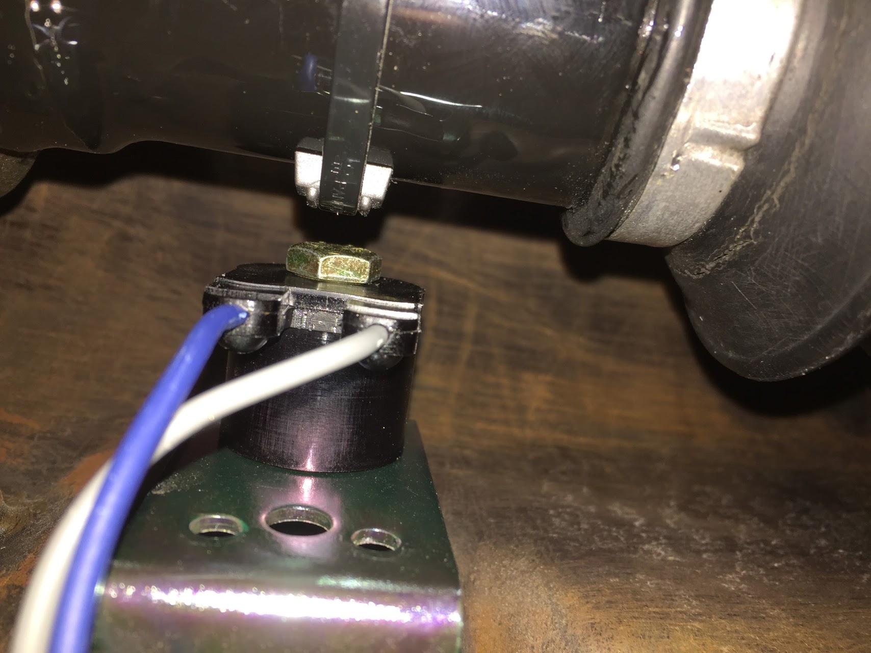
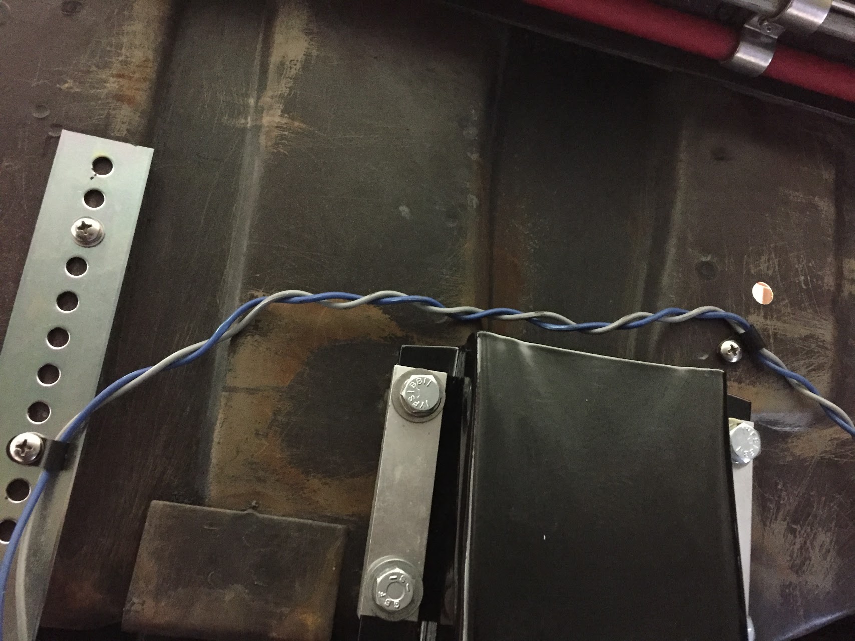
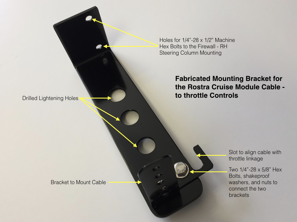
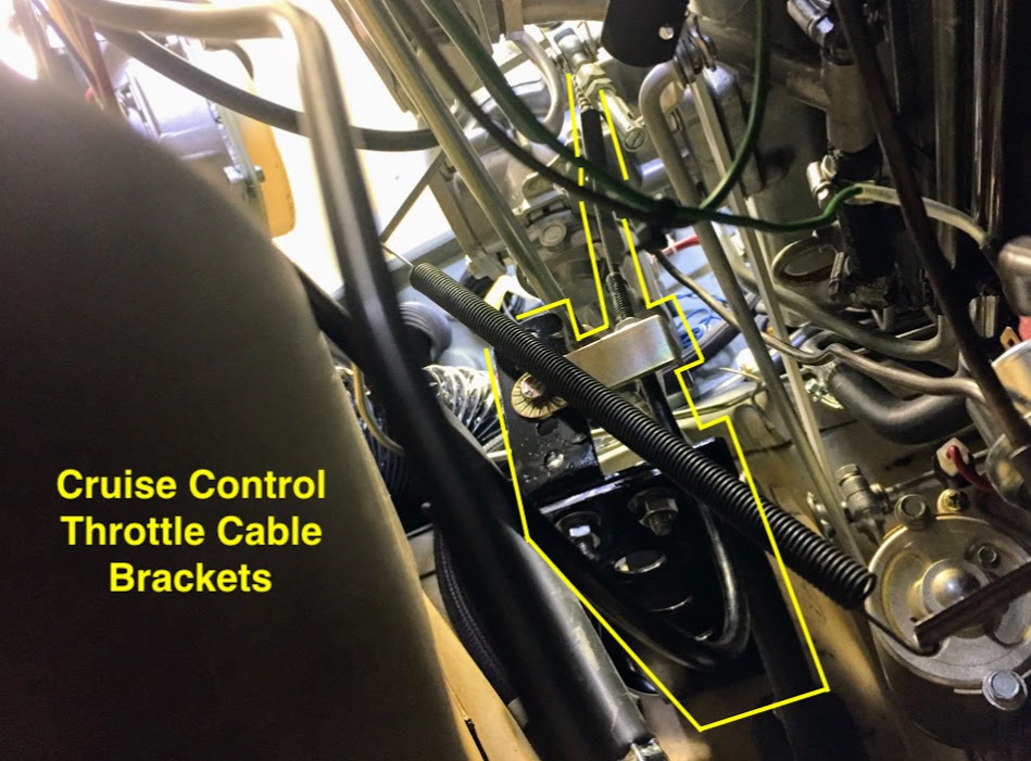
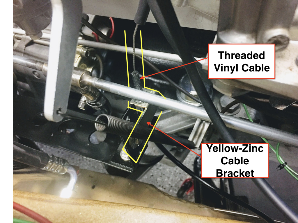
The final step is to determine where you will attach a new lever on the throttle shaft and then locate a bracket for the throttle control cable from the vacuum canister to the throttle linkage. Throughout my restoration I have avoided drilling any new holes in the car unless it was absolutely necessary. In all but just a few instances I have been able to work out a solution to mounting various components by taking advantage of screws or bolts already on the car. To do so with the cruise throttle control, I designed a bracket, that while a little complex for the purpose did allow me to use the two mounting bolts for the pedal box found on the top of the firewall diagonal brace. The images below show the bracket before and after painting. After painting it red it virtually disappears from view. I routed the cable from the vacuum canister through the firewall and mounted it to the fabricated bracket.

Cruise Control Bracket Image 24

Cruise Control Bracket Image 25

Cruise Control Bracket Image 26

Cruise Control Bracket Image 27
If the integrity of the original structure is less important to you, or if you are connecting the throttle cable in a different location on the throttle shaft (I used a lever on the very end of the shaft for the rear carb) then you can use one of the several brackets provided in the Audiovox kit or you can create your own as I did.
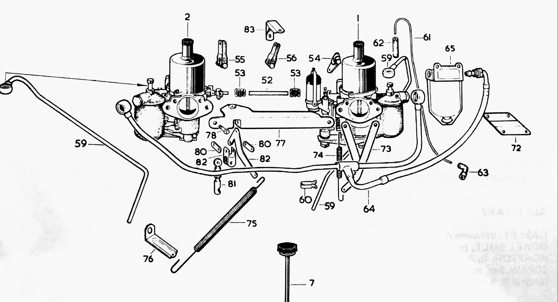
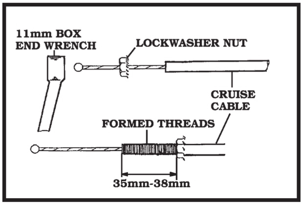
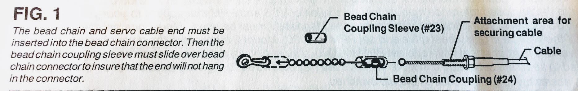
The kit directions indicate that there should be between 1 ½” and 2” total linkage travel. The servo throttle cable and the carb shaft lever are connected with a bead chain supplied in the kit along with couplers for each end of the chain. It is cut to the length required. A minimum of 5 beads should be used. In my case 10 beads were used. The number will of course vary depending upon the set-up in your car. The chain connection should provide for straight and free travel of the linkage when operated.
After the chain connection is made from the servo cable to the carb linkage, nothing remains of the assembly process other than taking the car out on the road and testing the system. I found the Audiovox cruise control to work quite satisfactorily. Perhaps not quite as smooth as the systems found on our vehicles today, but certainly functional and well worth the moderate expense.
Good luck with your installation. Just let me know if in your experience something could be made clearer in these instructions.
Click this link for a pdf file of the Audiovox Installation process: Installing the Audiovox CCS (low res)
Cheers and happy healeying!
Lin Rose
1960 BT7 “The Bloody Beast”
1959 AN5 Bugeye