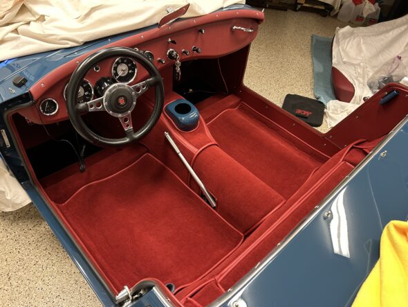
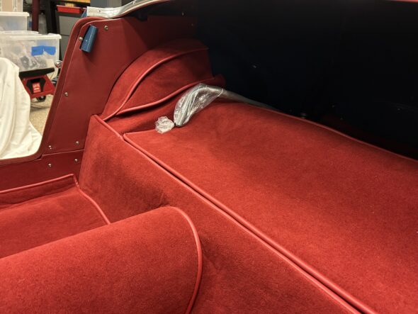
Interior Insulation and Panel Install

We will be using two types of insulation in the Bugeye. Dynamite Extreme will be applied directly to the metal surfaces in the interior. Then an aluminum duct insulation material sourced from Lowes will be applied on top of the Dynamite. Aluminum tape will be used to seal any seams in the materials.

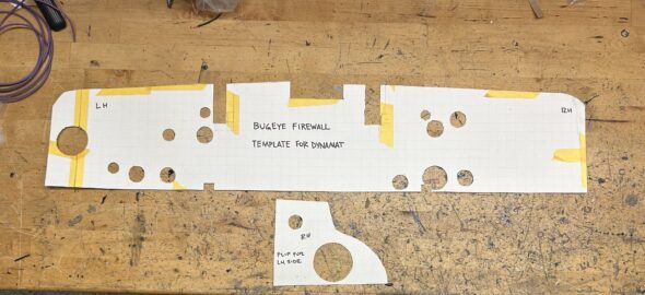
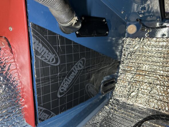
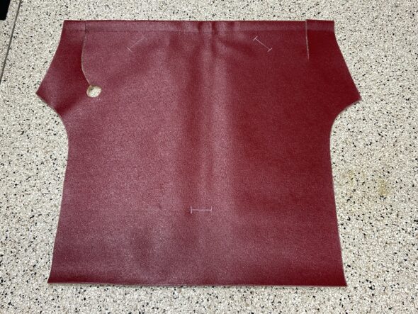
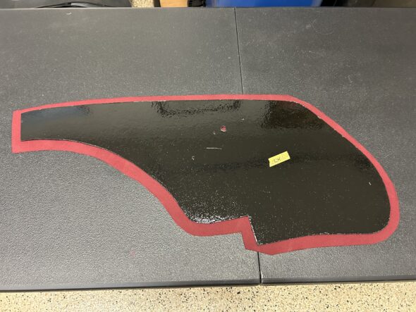
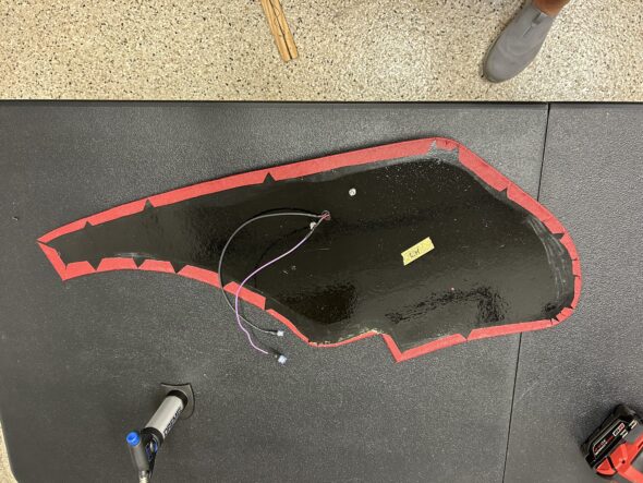
We began this process with the installation of the Dynamite Extreme on the interior of the firewall. This is a little tedious because one first needs to make a template to account for all of the holes in the firewall. The matching holes in the dynamat need to be of a larger diameter than the corresponding firewall holes to account for the rubber grommet that will fit in each hole.

Firewall Dynamite Extreme Template

A small applicator wheel was used to press and smooth the Dynamat material against the metal surface. A Gorilla Glue spray contact cement was used to glue the aluminum insulation to the Dynamat. 

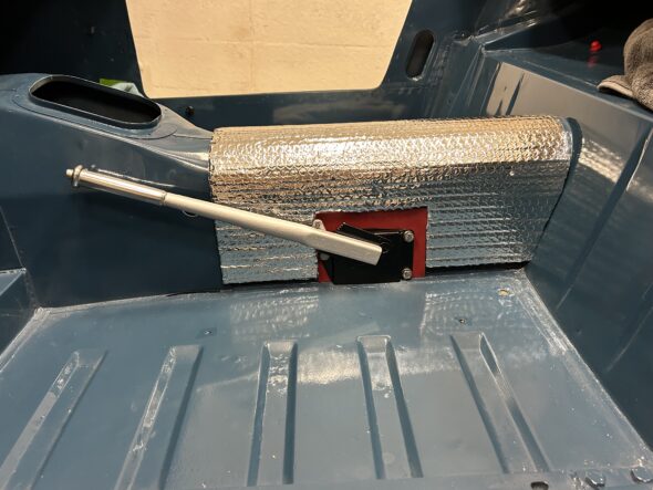
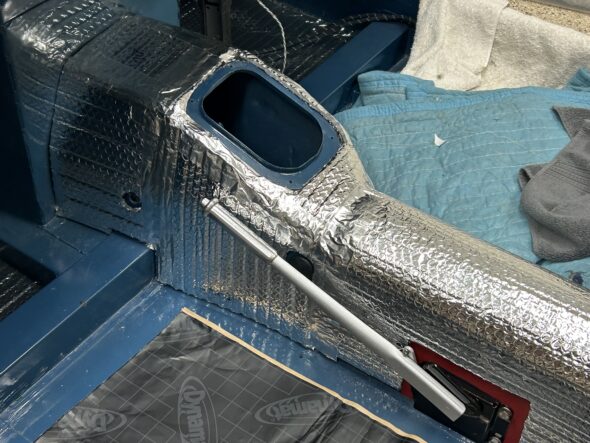
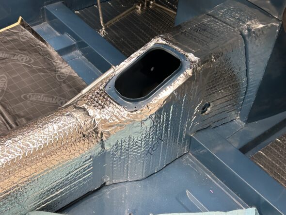
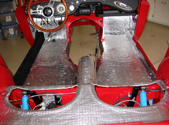
We then began the installation of the Dynamat Extreme and aluminum insulation throughout the interior. The first location was the driveshaft tunnel after we installed the handbrake.

Dynamat Extreme and aluminum insulation on propshaft tunnel

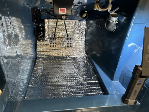
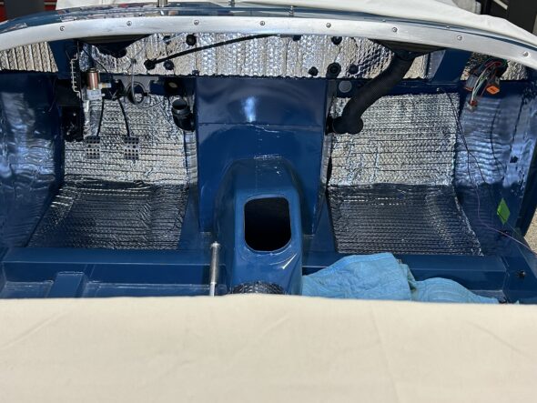
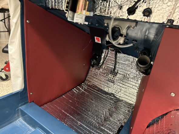
Then we moved to the floorboards in the footbox.

LH footbox insulation

Both sides

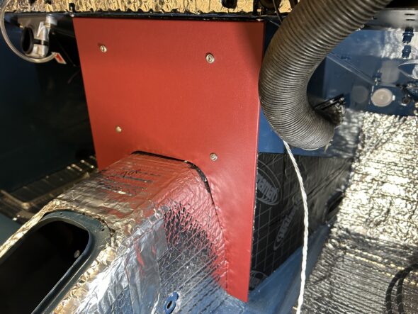
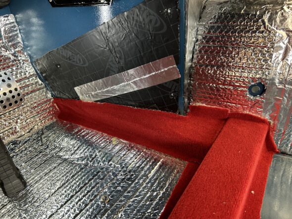
We tackled the gearbox tunnel next. It isn’t very large but lots of angles and curves so it took a while to complete.

Gearbox Tunnel with Dynamat and Aluminum Insulation

Gearbox Tunnel with Dynamat and Aluminum Insulation

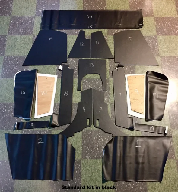
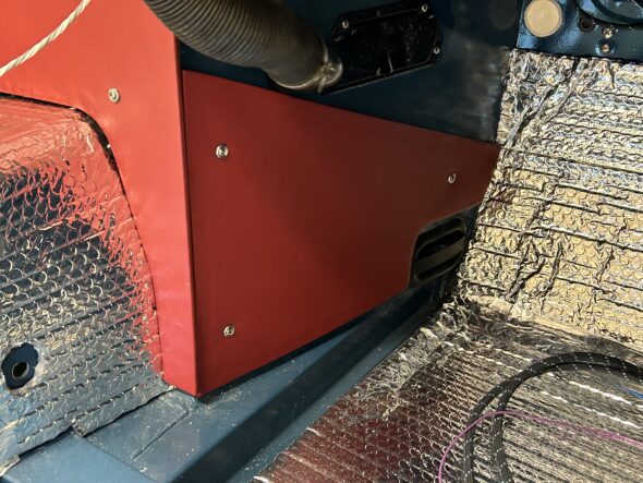
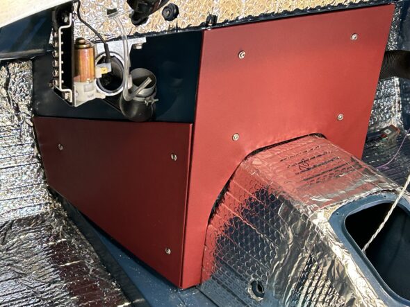
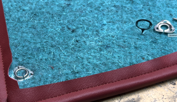
The next area to address was the box around the gearbox bell housing and the rear of the engine. This consists of three surfaces that are covered with upholstered panels. On these three surfaces we chose to use only Dynamat Extreme and to forgo the aluminum insulation. The concern was that we would not be able to get a tight fit with the intersection of the panels. The stainless steel finishing screws and trim cup washers were supplied by Bugeyeguys.com.

We installed the Dynamat and the upholstered panel on the front central face of the box first.

Center Panel Install

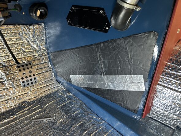
Then we worked on the RH passenger side:

RH Dynamat Install

RH Upholstered Panel Install

The we moved to the LH driver’s side insulation and panel install:

LH driver’s side insulation install

LH driver’s side upholstered panel Install

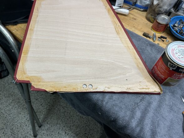
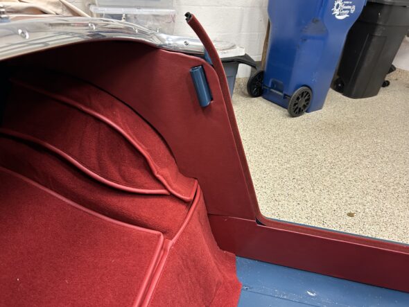
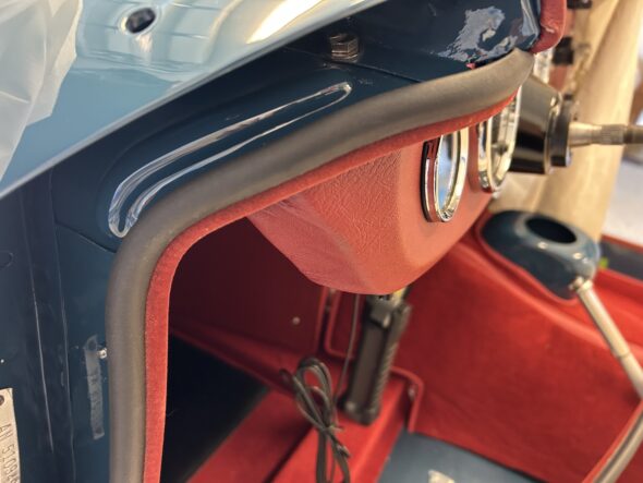
On both of the outside kick panels in the footboys we had to do some trimming to get a nice fit to the fur flex seal. This involves pulling back the vinyl, trimming the board and re-glueing the vinyl.

Footbox panel modification

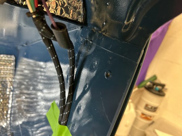
This is a photo of the modified panel installed. Very nice abutment to the fur flex. The upper mounting screw is a #10 machine screw mounted to a rivnut that was previously installed.This was done on both sides of the car to prevent a sharp pointed self-tapping screw from protruding into the door cavity.

LH Footbox panel installed

Rivnut for upper mount of the kick panel

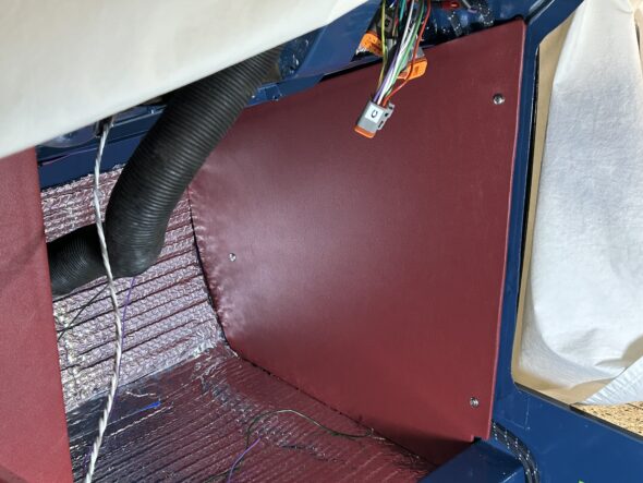
Installing the RH kick panel was next. The wiring made this one a bit of a challenge but we got it in place.

RH kickpanel installed

There will be more to add to this post as we continue with the installation of the insulation and finish panels but we are going to go ahead and publish this now and will add more content as progress is made. Bugeye Restoration Video Episode Eighty-three covers the work done with the interior insulation and panel installation to this point and it’s content is listed below:

https://vimeo.com/1000378868/cb7b3558a6?share=copy

0:00 – Cleaning floorboards

0:20 – RH side blanking screws

0:39 – Dynamat Extreme installed

1:01 – Aluminum insulation installed

1:30 – Insulation on gearbox tunnel installed

1:35 – Dynamat Extreme insulation on gearbox tunnel

1:52 – Aluminum insulation on gearbox tunnel

2:22 – Engine surround insulation and panel install


Handbrake Installation

We had previously refurbished the handbrake assembly. This was detailed 24:23 minutes into the Bugeye Restoration Video Episode Forty-two. https://vimeo.com/832369002/c87fd61c10?share=copy..  Further handbrake restoration was highlighted at the very beginning of Bugeye Restoration Video Episode Forty-fourhttps://vimeo.com/842617175/d7a040b143?share=copy

Before we could actually install the handbrake we applied Dynamat Extreme sound insulation to the propshaft tunnel and then glued aluminum duct insulation to the Dynamat Extreme for added heat insulation. We then glued some red vinyl to the area around the handbrake bracket.

Bugeye Restoration Video Episode Forty-eight shows the application of the insulation and the mountng of the handbrake assembly to the tunnel. Once the Rear axle is installed we will connect the handbrake cable to the brake cross rods. https://vimeo.com/986085408/43c579f77a?share=copy


Cooling/Heater

Managing the heat generated by the operating engine, whether in the engine itself, in the engine bay, or in the interior is an issue in the Big Healey. What may not have been an issue in more temperate Great Britain, is a different story in the U.S. Over the years Healey owners have gotten progressively better at managing the heat issues. I made a number of enhancements to The Bloody Beast to help with cooling or at least improved insulation from the heat.

 The Original Cooling System

The capacity of the cooling system, excluding the heater, is 21.6 U.S. pints. The original thermostat was 158 degrees.

Cooling System Modifications

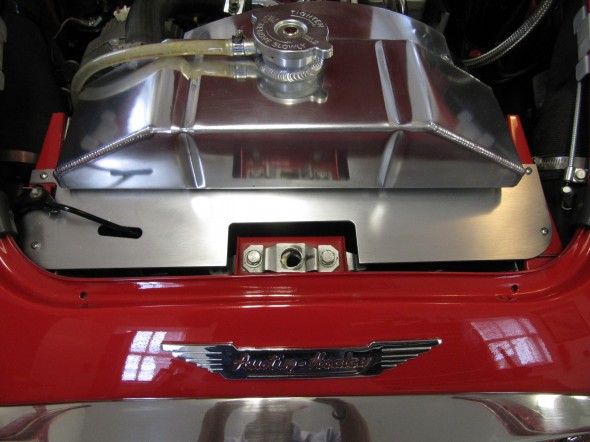
Aluminum Radiator

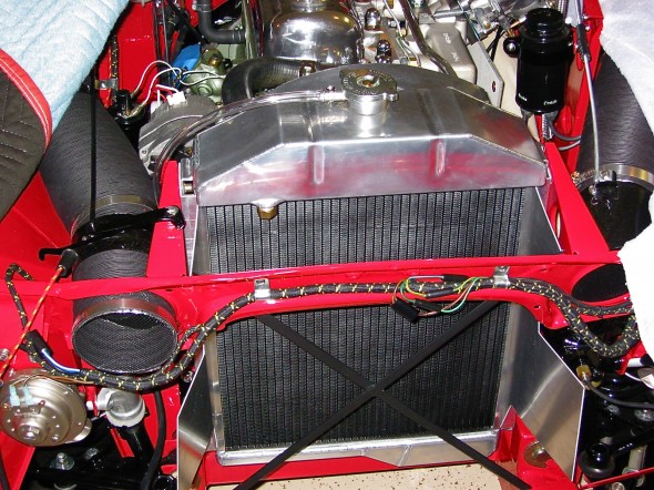
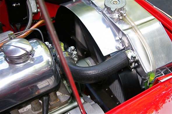
Recoring the original radiator with a more efficient tubing system is one option pursued by many enthusiasts, another is replacement of the original radiator with an aluminum alternative.  I chose the replacement route with an alloy radiator sourced from Cape International. In addition to the benefit of improved cooling, the polished aluminum header tank looks great in the engine bay! I painted the core with black radiator paint so that the “X” brace in the front of the car would “disappear” when looking through the grille.

Aluminum Radiator

Aluminum Radiator

Air-Intake Deflectors

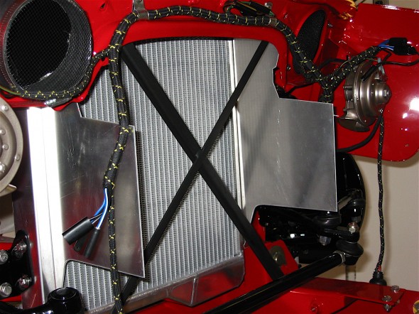
The Healey has a multi-piece air-intake deflector assembly as original equipment; however, I was not happy with the gap that exists between the assembly shrouds and the radiator. This permitted air to escape around the radiator into the engine bay. The original deflectors are also a bit of a pain to install. I decided to fabricate some deflectors from aluminum stock. After constructing cardboard patterns I had the aluminum bent at a metal working shop. The deflectors are slotted to fit alongside the radiator in the standard radiator mounts to the frame. The image below shows the fitting of the deflectors before the radiator core was painted. As you can see this produced a tight fit around the radiator sides – no air escapes now!

Radiator Baffles

Radiator Baffles

Upper Radiator Shroud

My friend, Mick Nordquist, had an upper shroud made for his Healey radiator to keep the air coming through the grill directed to the radiator rather than escaping over the radiator. He supplied the pattern for me and I had one cut with a plasma cutter from 2mm aluminum plate and installed it with four stainless steel #8 self-tapping screws. In addition to improving cooling, I think it also offers a nice cosmetic improvement.

Radiator Top Shroud

Radiator Top Shroud

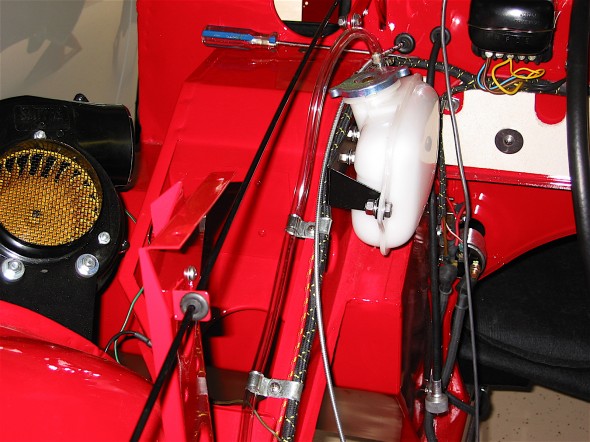
Coolant Recovery System

The original cooling system design provided for no ability to capture coolant whether just an expansion tank or a true pressurized recovery system. Healay owners, particularly if they have filled their radiators to maximum capacity are use to their car’s “burping” in the parking lot after being driven. I purchased my coolant recovery system components from Cape International.

Coolant Recovery System

Coolant Recovery System

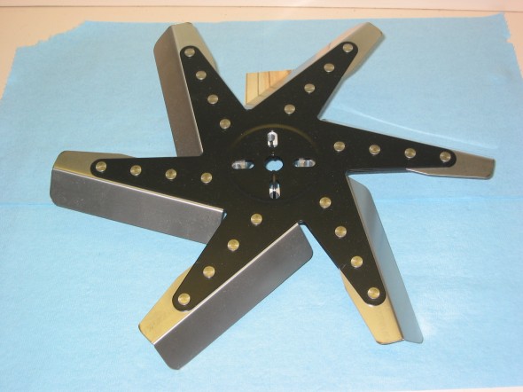
Six Blade Stainless Steel Fan with Spacer

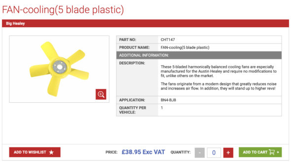
A number of alternatives to the original fan are available to the Healey owner today. The “Texas Cooler” and the variable pitch stainless steel fans are probably the most popular. I initially decided to go with the stainless fan available from British Car Specialists. However, the fan is pretty noisy so I switched the fan in 2020 for a nylon/plastic asymmetric fan similar to the “Texas Cooler” fan. The new fan was sourced from AH Spares. Time will tell but the new fan seems to keep the engine temperature under control and it is quite a bit quieter than the stainless steel fan.

Stainless Fan

Stainless Fan

AH Spares Fan

Fan Shroud

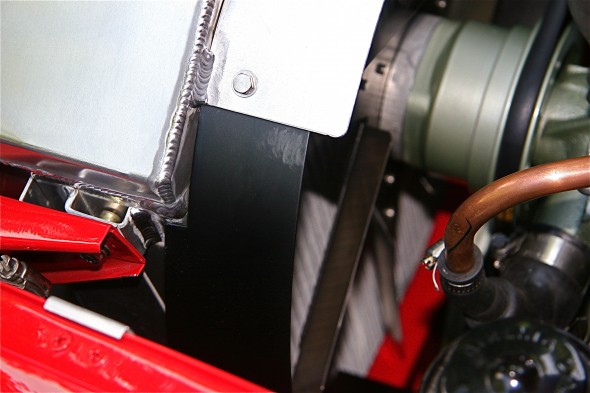
The custom air deflectors improved air control on the intake side of the radiator. To help channel the air on the fan side of the radiator and to add a safety component (those stainless fan blades are very sharp!!) I added a two piece shroud also available from British Car Specialists. It did not fit exactly as it would to the stock radiator, but a little tinkering and it fit beautifully. Since it was added after the restoration of the Bloody Beast was completed, I can say that the shroud was definitely responsible for some additional temperature reduction.

Radiator Shroud

Radiator Shroud

Radiator shroud

Radiator shroud

The Original Heater/Interior Cooling

The original heater was a Smith’s hot water circulating unit, part # 8G9048. It was assisted by a fan blower secured to the right front wheel arch assembly. Fresh air was supplied to the driver’s side of the interior by a 4” paper/metal hose controlled by a fresh air assembly mounted at the front of the car.

Heater/Interior Cooling Modifications

Sealing all of the holes in the firewall is the first thing to be done if one is to keep the heat and fumes out of the interior. A helpful tip someone shared with me was to wait until dark and put a light in the engine bay. This way any holes or leaks can be easily spotted from the interior.

Dynamat Extreme and Aluminum Duct Insualtion

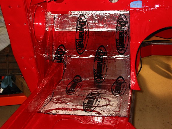
A number of products are on the market to help reflect heat and offer both heat and sound insulation. Dynamat Extreme is certainly on of the most popular. I applied Dynamat Extreme heat reflective and sound insulation material to my interior first. I then applied aluminum duct insulation on top of the Dynamat and under the carpet. All seams were sealed with aluminum tape. These two together have proven to be very effective in keeping the heat out!

Dynamat Extreme

Dynamat Extreme

Aluminum Duct Insulation

Aluminum Duct Insulation

Modern Heater

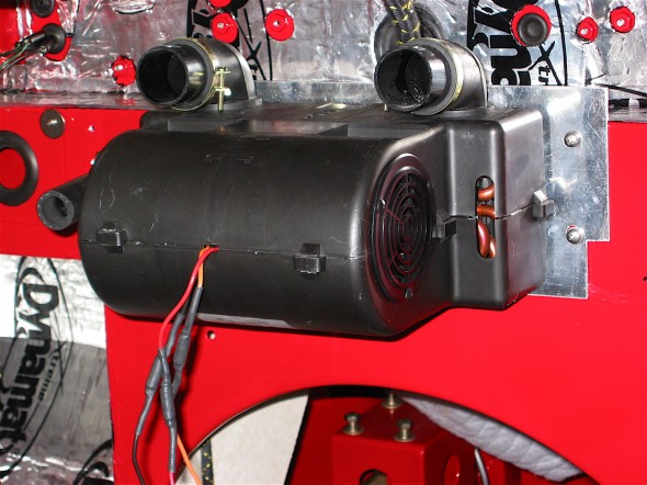
For those (rare) occasions when I would choose to have more heat in the interior spaces, I chose to replace the Smith’s Heating unit with a contemporary unit supplied by Cape International. This unit has an internal two speed fan.

Cape International Heater

Cape International Heater

Fresh Air Supply

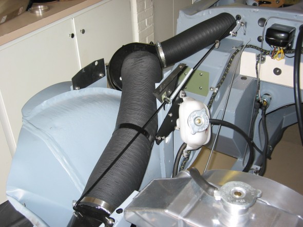
The original design of the car provided for some fresh air being delivered to the LH driver’s side of the car. Given that the Cape International Heater has its own fan, that left the original Smith’s blower to be used to blow fresh air into the passenger side of the car. I installed an air intake valve (upside down) just like the one on the LH side of the car, on the RH side, and then wired the blower to provide fresh air on the passenger side when desired. To be honest, I have found this to be useful for some ventilation when one has the hardtop in place, otherwise I am not sure that it was worth the effort! There are more details about this project in the restoration blog.

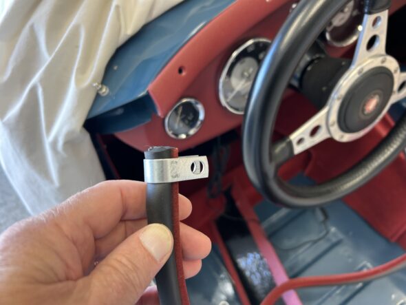
Ventilation Hose Assembly

Ventilation Hose Assembly

zz

Chapter 78 Week Forty-Eight November, 12 2007

I ordered some 6mm black rubber tubing from British Wiring to sheath the choke cables. It gave a slightly loose fit, but I think it will be fine. I installed it on both cables. I painted and installed the propshaft made for me by Dale Engineering.

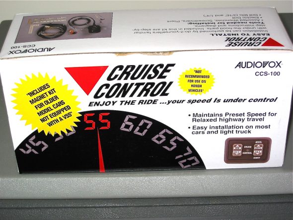
I purchased the cruise control unit, made by Audiovox, from J. C. Whitney.

Audiovox cruise control

It was fairly inexpensive and appeared to be a high quality kit. A complete set of installation instructions is available from the Cruise Control pdf document I created. Not much helpful information was available from other Healey owners who had done the install, although I did find one well done article that is in the October, 2002 edition of the Healey Marque Magazine. Alan Teague and Carl Brown from North Carolina did provide some useful tips and photos and I am grateful to both of them. Installing the Audiovox CCS

(This is a large file that takes a while to open, be patient)

The key components included installing the magnet and sensor at the propshaft, the location of the servo canister, the vacuum line and throttle connections, the control module, and the wiring.

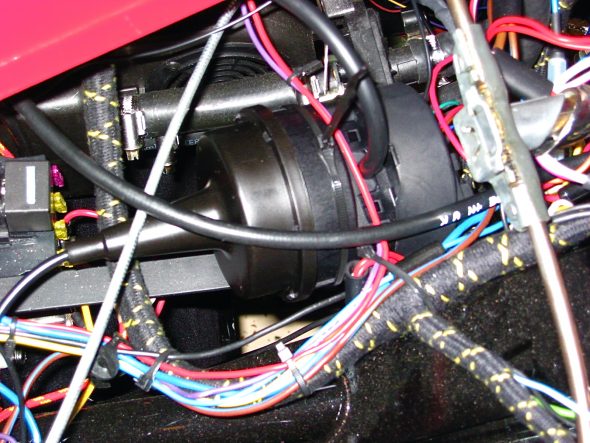
I installed the servo above the dash panel support bracket to the right of the steering column with two 11” plastic ties, rather than using the supplied metal bracket. I know from other’s accounts that the unit makes some noise when it is operating, but not knowing if it is an offensive level or not, I wanted to mount the servo temporarily. If the unit turns out to be noisy, I will move it into the engine bay later.

Servo installed

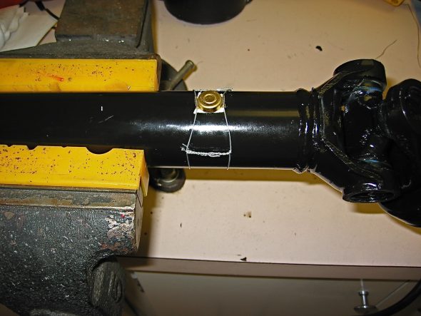
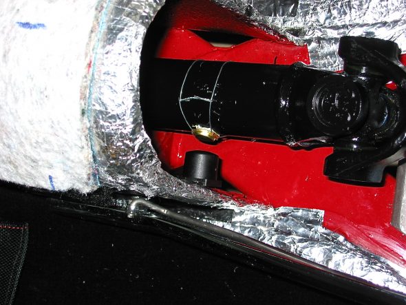
Wiring the magnet to the propshaft should really be done with the shaft removed from the car if you want to do a nice installation. I located the magnet while the propshaft was in the car, aligned the sensor and mounted it on the right side of the gearbox tunnel, removed the propshaft and safety wired the magnet and then reinstalled the propshaft. If you want to do a nice job, I highly recommend using safety wire twisting pliers. They make the job much easier and result in higher quality work. I got my pliers from Aircraft Spruce.

Cruise control propshaft 6

Cruise control driveshaft sensor 2

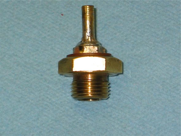
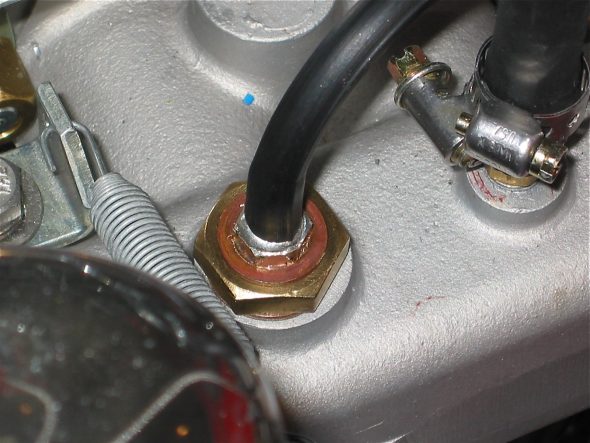
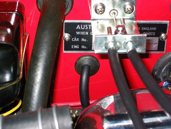
Installing the supplied rubber vacuum line required taking the line through a firewall rubber grommet that was not previously used, and then modifying the larger nut on the intake manifold with a fitting to permit connecting the hose for vacuum at the manifold.

Homemade vacuum fitting

Cruise vacuum fitting 1

Cruise Vacuum Line grommet

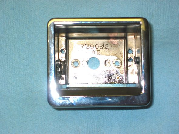
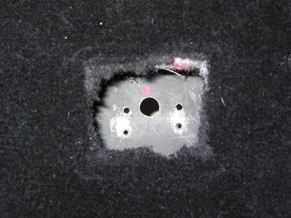
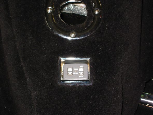
After setting up the magnet, sensor and vacuum servo the next task was to complete the installation of the cruise control panel. I followed the course of others, taking advantage of the panel’s small size and installing it in the ash tray. This provides a convenient location for controls and also “hides” the panel when desired. I simply drilled a 1/2” hole in the bottom of the ash tray and in the gearbox tunnel bracket for the ash tray to permit the routing of the wiring.

Modified ash tray for cruise 1

Modified ash tray for cruise 2

Cruise control panel

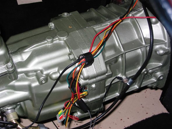
The cruise control wiring appears daunting at first, but with patience it can be accomplished by a novice. Since on the BT7 the speedometer cable runs behind the gearbox extension, I decided to run the cruise control wires down the same path to get all of my wiring “under” the gearbox cover. Again, details are provided in the Cruise Control pdf file. Black, twin tailed wire to the magnet sensor, black single wire to ground, grey wire to headlamp switch for illumination of the control panel in the ash tray, red wire to the light green wire on the brake switch that is hot whether the brake pedal is depressed or not, the purple wire to the green/purple wire on the brake switch (the one that is hot when the pedal is depressed), blue wire to (-) terminal on the coil, yellow, green and purple and red wire to the 4-pin connector, the orange fused wire to a power source when the ignition is switched on.
Cruise witring along gearbox

With the wiring complete, the only remaining task is locating and connecting the throttle control. That job will have to wait for next week’s work.

Chapter 77 Week Forty-Seven November, 5 2007

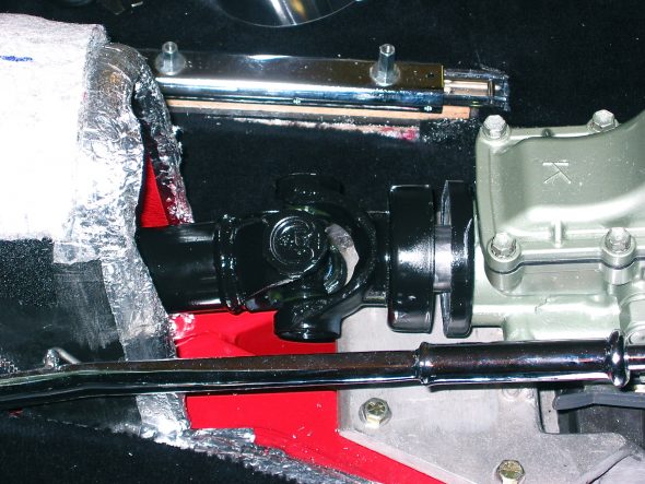
In final preparation for starting the Bloody Beast, I installed the propshaft and filled the Toyota gearbox with just shy of 3 quarts of MT-90 oil using the side filler hole and filling until oil started to dribble out of the filler opening.

Propshaft installed

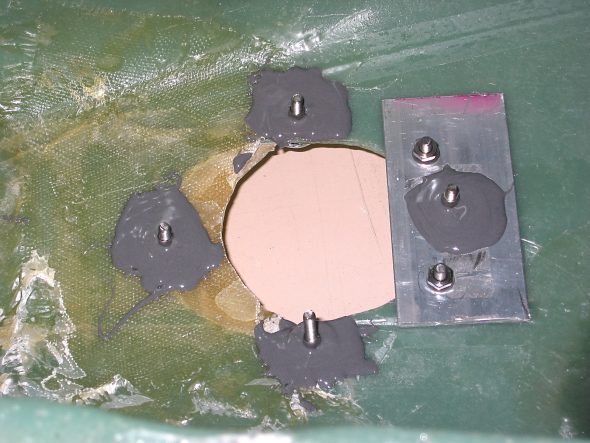
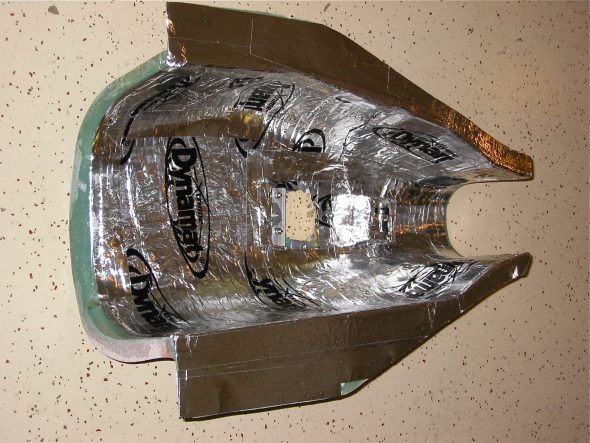
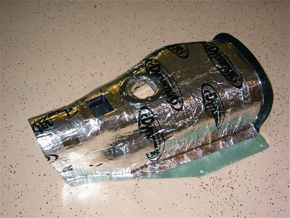
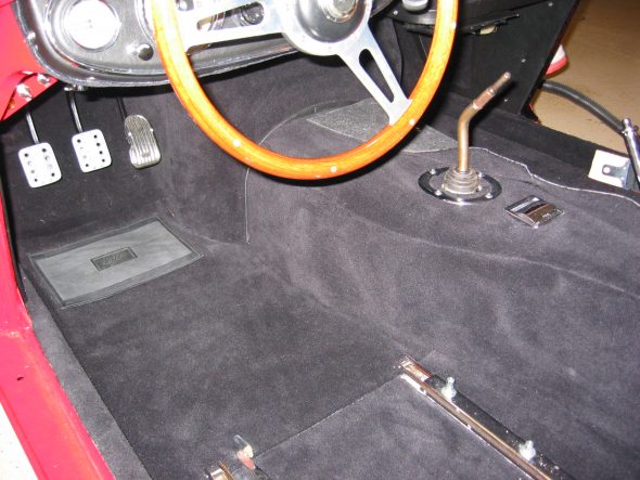
I had been waffling on whether or not I would install the ash tray in the gearbox cover, but I decided to go ahead and do it. If I equip the car with cruise control, it will serve as a great location for the control module. I cut a hole in the fiberglass cover an JB welded the bracket to the cover. The next step was to cover both sides of the gearbox cover with Dynamat Extreme.

shift ring JB Weld

Gearbox cover with Dynamat 1

Gearbox cover with Dynamat 2

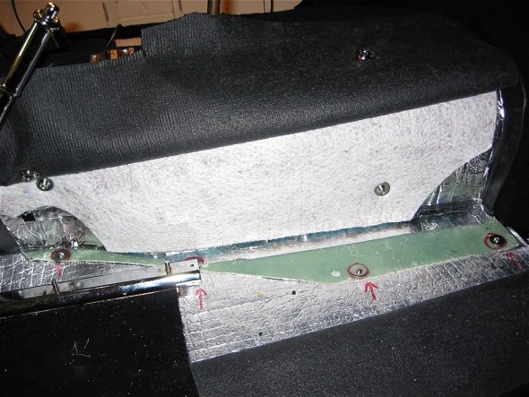
Fitting the carpet and padding to the gearbox cover was not a job that I had been looking forward to doing. Not so much hard as awkward. I installed two carpet snaps through the padding provided by Heritage Upholstery and Trim on each side of the fiberglass gearbox cover. I installed these with #6 machine screws with large washers and nuts, rather than with self-tapping screws since I was fastening to fiberglass instead of metal.

Gearbox padding

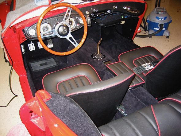
I also cut some padding to go over the end of the gearbox tunnel and I fit it with velcro. The carpet was carefully cut to fit through trial and error with the help of some chalk. Holes were drilled in the gearbox cover flange and the assembly was mounted to the car. Everything seemed to be nice and tight, although I will do some seam sealing to the underside of the assembly before completing the job. I was satisfied with the final product!
Carpet installed 3

LH carpet installed 2

Chapter 76 Week Forty-Six October 29, 2007

I am not quite ready to start the engine because I am waiting on my custom made propshaft, currently being fabricated by Dale Engineering. However, there were some close to final matters that needed attention as the day to fire up the engine approached. Jack Harper from Coachworks, Ltd. who assembled my rebuilt engine, came to the house to assist with readying the engine.

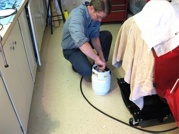
Our first step was to “pump” some engine oil into the engine to ensure that everything was coated. Jack attached a compressed air canister with two quarts of oil to the oil pressure pipe union and then forced the oil into the engine with air pressure. As we neared the end of the oil transfer one could see the oil emerging from the top of the rockers and then the end of the transfer was signaled by a large “burp” that one could easily hear.

Jack Harper engine oil

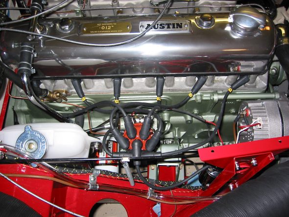
We made sure the pointer and timing mark were aligned and then went about checking the valve gap for the assembly. I used the starter to turn over the crank as we checked each rocker/valve. We then secured the Capesport Alloy rocker cover and added another 5 quarts of oil. The rocker cover was sourced from Cape International.

Capesport Rocker Cover & Ignition Wiring

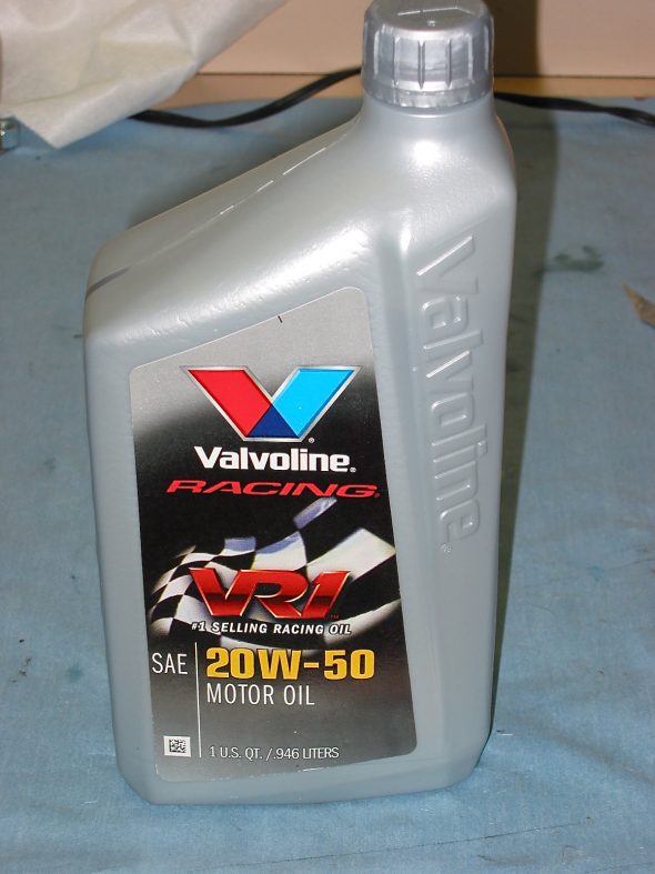
The oil I chose to use is Valvoline racing oil, 20-50 with ZDDP.

Valvoline 20-50 Oil

I had taken the NGK spark plugs out to rotate the engine. We put a little anti-seize on each plug, checked the gap and re-installed each one.

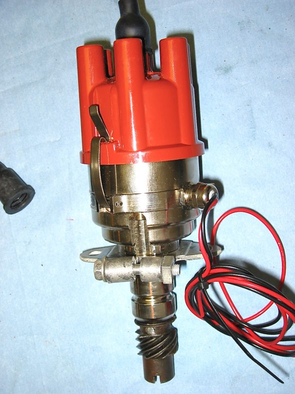
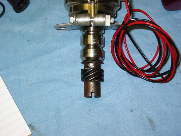
In recent months the 123 distributormanufactured by a Dutch company, 123 Ignition, has received some very good press. I had originally planned to use a Mallory Unilite distributor, but I decided to give the 123 unit a try.  One appealing aspect of the 123 is that the advance curve is determined by simply adjusting the settings by turning an adjustment on the outside of the distributor and “clicking” it into place. For initial set-up, I chose the recommended “B” setting. While the distributor is a “drop-in” in for the BJ8 with an electronic tach, a kit is supplied to adapt it for the mechanical tach drive of the BT7. The shaft did need to be drilled and the drive dog from the original Lucas unit installed with a few spacing washers. My unit was supplied by a German vendor Brits’N’Pieces. Jack installed the distributor and I installed the Pertronix igntion wiring to the plugs and to the Pertronix “Flamethrower” coil. The coil was previously mounted vertically on the shroud brace. Several of the wiring leads on the original wiring harness for the ignition were no longer needed so I simply used plastic ties to fold them down and secure them, in case they might be needed at some point in the future.

123 Distributor

123 Distributor drive dog

123 Distributor.  Purchase Information and instructions.

My next step was to add coolant to the radiator. I used Prestone 50/50 premixed formula. Fortunately no leaks!

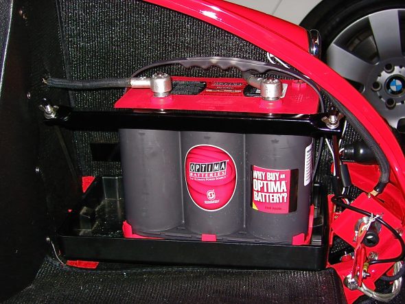
I had been using an old battery for checking out electrical function throughout the restoration process, but it was now time to buy the battery I would be using in the vehicle when it was a road car and not a garage car! I decided on the Optima. I purchased it at the local Batteries Plus store. They are not cheap at about $160 dollars, but I like the idea of the no-leak gel in the boot of a car. The model number I purchased was: Part Number: 34 (8002-002) RedTop®; Battery; Group 34; Cold Crank Amps 800; Crank Amps 1000; Reserve Capacity 110; Ampere Hour 50; Top Terminal; L-10 in.; W-6 7/8 in.; H-7 13/16 in.; UNBOXED. The battery was secured in place with the battery fixing bar and rods.

Optima Battery

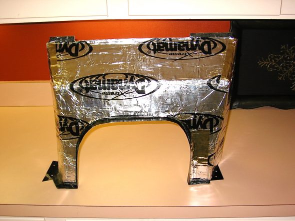
Because the Smitty Bell housing fit a little high in my car????, I custom fabricated a gearbox cover extension to provide a little more room for the housing. This also required custom fitting carpet. I had ordered a couple of extra yards of carpet when I ordered my interior from Heritage Upholstery and Trim for this purpose. I first covered both sides of the cover with Dynamat Extreme and then cut and glued the carpet to the cover.

Gearbox cover extension 1

To assist with interior cooling and weight, I ordered a fiberglass gearbox and propshaft cover from British Car Specialist. The original cover was metal and mine was too far gone from rust. Using a fiberglass cover also made it easy to fill the original hole for the side shifter and cut a new hole in the center for the Toyota gear shift. I used an MGB trim ring and rubber seal for the gear shift lever sourced from Moss Motors. Using a helpful hint from Doug Reid, “Mr. Finspanner,” some JB Weld was used to glue four “T” nuts to the bottom of the fiberglass cover so that machine screws could be used to mount the ring, rather than sheet metal screws that overtime would fail to secure tightly in the fiberglass.