Spark Plugs
I don’t know if I will stick with the Champion plugs or not, but Mike Gassman installed Champion RN11YCA plugs when the engine was rebuilt and they remain in the engine at this point.
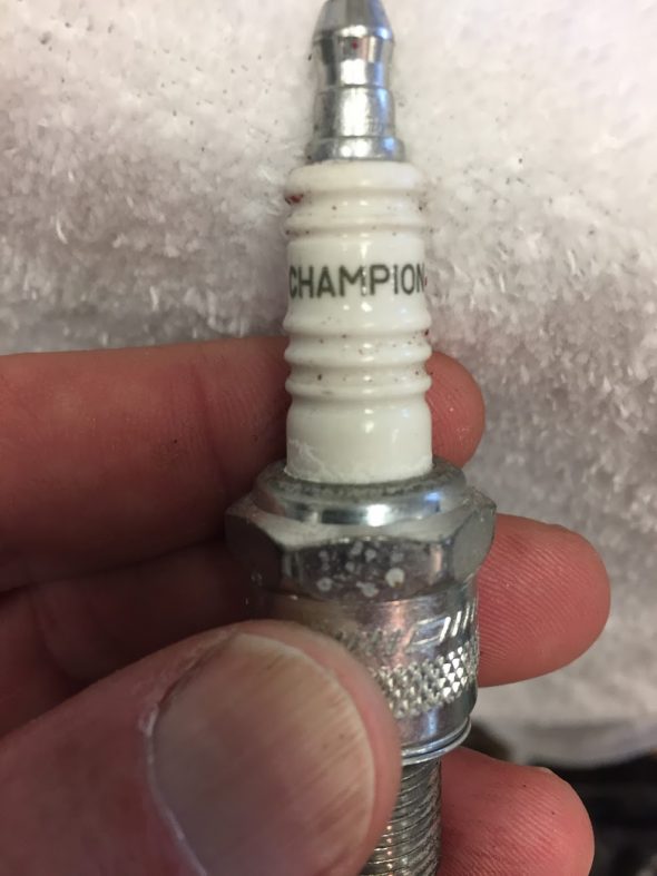
Champion Spark Plug Jag MK2
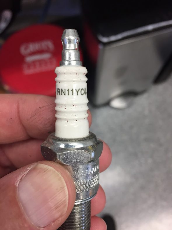
Champion Spark Plug RN11YC4 Jag MK2
Distributor
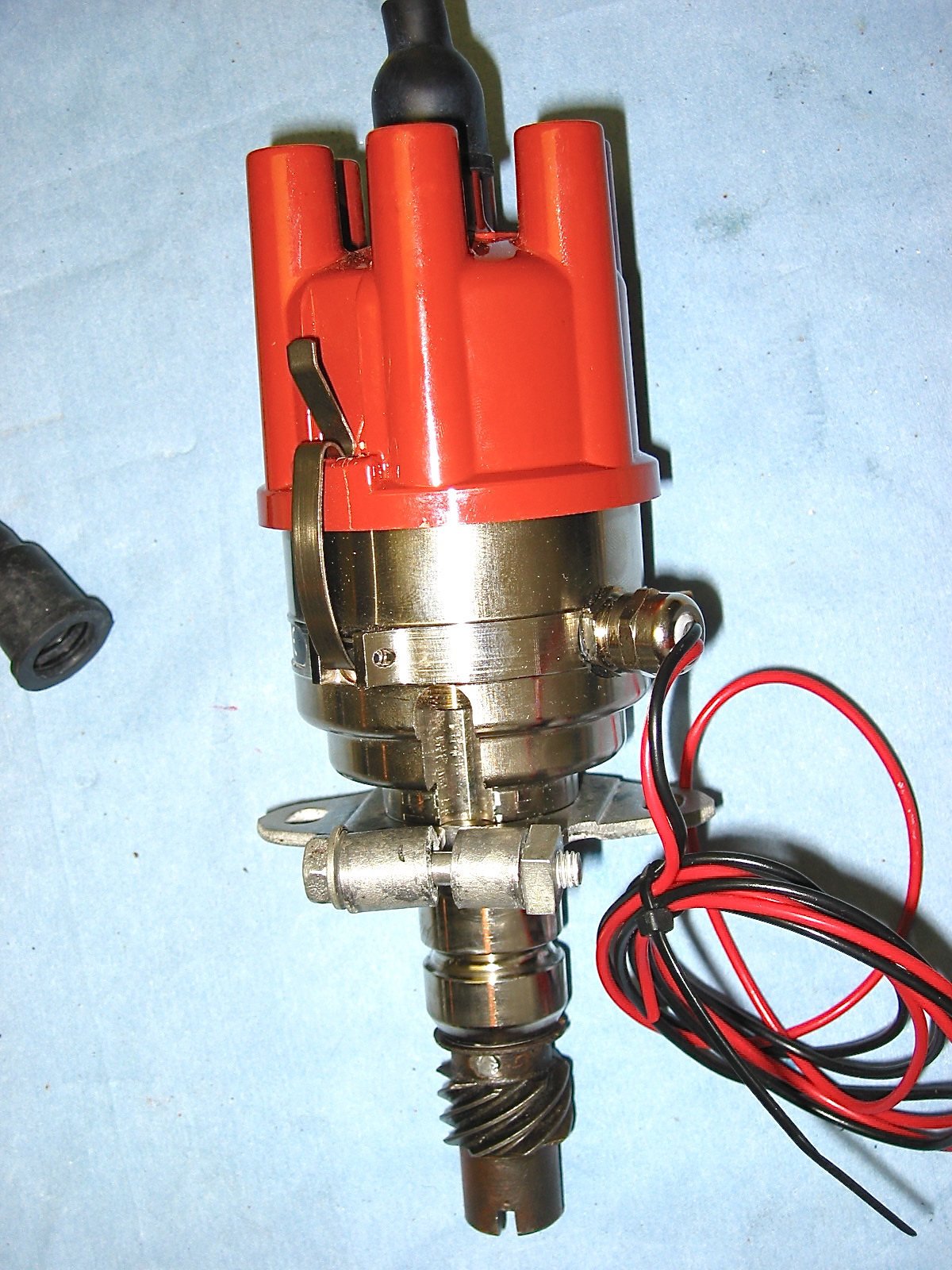
There are several options available for upgrade to an electronic ignition. I used a 123 Electronic Distributor on my 1960 Austin Healey 3000 and was very pleased with the installation so I ordered the same distributor designed for the Jaguar XK motor – negative ground. The company that produces the distributor is located in the Netherlands. This is the link to their website: http://www.123ignitionusa.com/jaguar.html.
I ordered the “Jag 6-R-V” from Classic Jaguar, 9916 Hwy 290 West, Austin, TX 78736 (512) 288 8800 Austin, TX. http://classicjaguar.com/cj/ign_sys.htm for $425.00.
This web site provides some useful commentary on the 123 distributor, although it should be clear that I am using the Jag specific model, not the generic british model.
http://jaguaretype.wordpress.com/home/technical/123-distributor/
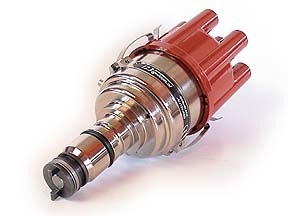
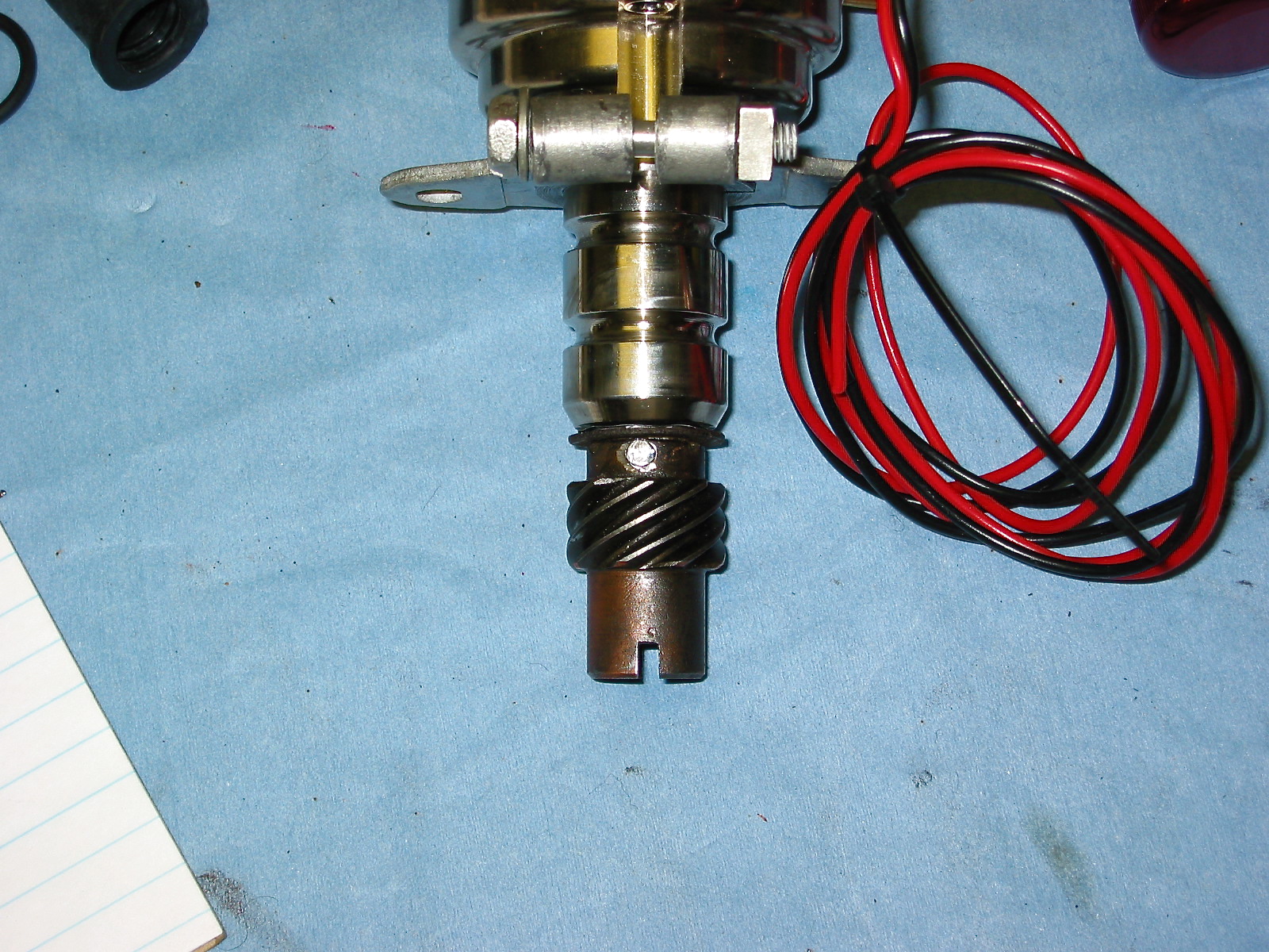
123 Distributor
Directions for Installation Provided with the Distributor
WITH THE OLD DISTRIBUTOR STILL IN PLACE
1. Mark the output towards cylinder #1 on the cap.
Remove the low voltage cable from the distributor to the coil, and remove the cap.
Now ask someone to crank the starter, and make a note: is the rotor rotating clockwise (CW) or is it rotating counter-clockwise (CCW)?
2. Crank the engine in its normal direction until you see that the rotor points toward the mark you made for cylinder #1, and verify that the static timing-marks of your engine align.
Do not rotate the engine anymore!
3. Check the firing order of the cylinders.
Use your workshop manual, or follow the cables from the cap to the spark plugs.
You start with cylinder #1, and remember to count in the direction that you have found earlier.
Make a note of the firing order, too. E.g. ‘1-4-2-6-3-5.’
4. Check which advance-curve is required for your engine. Use your workshop manual, check the model number of the existing distributor. Also compare the curve-listings for the various models in this manual.
OUT WITH THE OLD DITRIBUTOR, IN WITH THE 123 IGNITION!
5. Turn the ignition off, and (with the engine still in the static position for cylinder #1) and remove the old distributor.
6. Using an 8mm Allen wrench, open the cap at the side of the 123 Ignition. Rotate the micro-switch to select the proper advance curve using a small screw driver. Close the cap tightly.
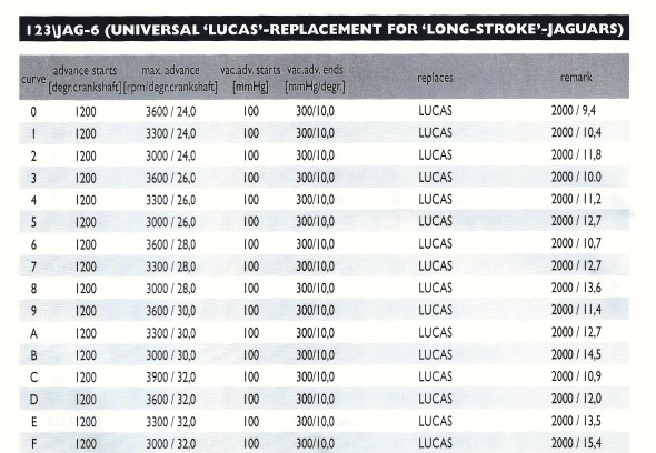
123 Ignition JAG-6 Curves
7. Mount the unit carefully, and ensure that the drive-dog mates correctly. Find a position so that the vacuum nipple and cables come out conveniently. Fasten it in such a way, that you can still rotate the new distributor.
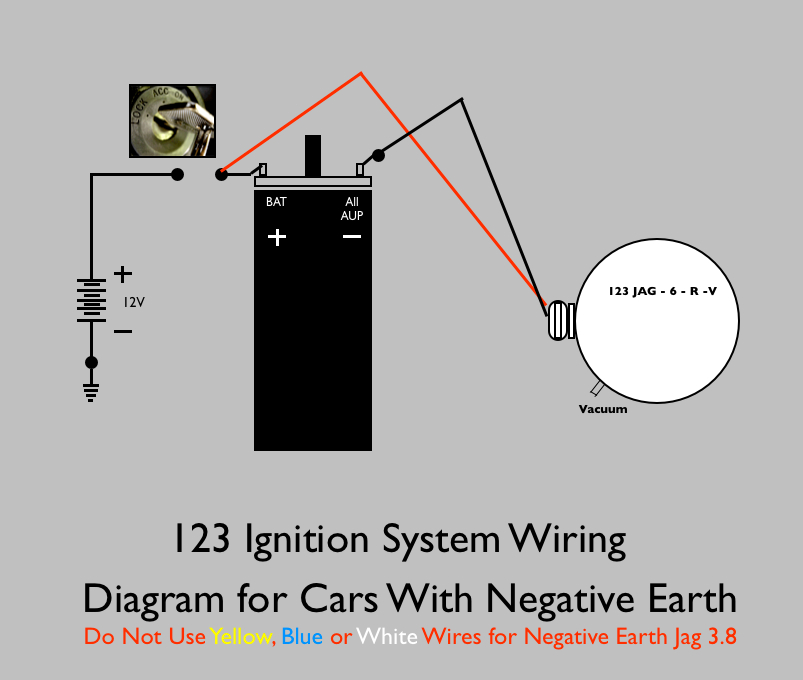
8. Follow the appropriate wiring diagram on the last two pages of the manual, but leave the black wire unconnected for now.
9. Turn the ignition on. A timing LED shines through one of the six holes in the aluminum disc. Rotate the body until the LED is “off.”
Now slowly rotate the body OPPOSITE to the direction that you have found under point 2, until the green LED just lights up. While turning the body, also press the rotor in the same direction to remove any free-play in the drive gear. Now, tighten the 123 Ignition securely.
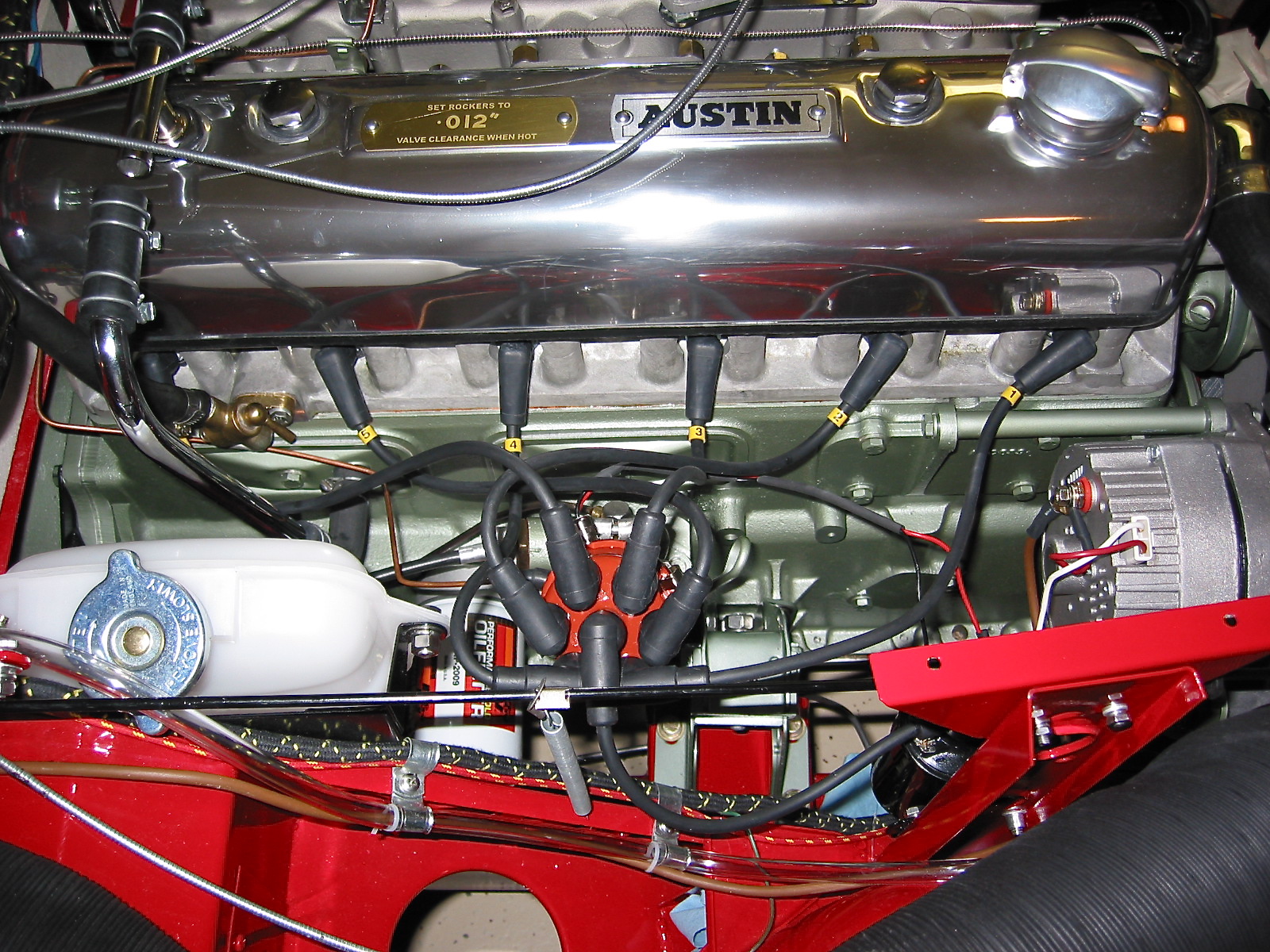
10. Connect the black wire to the coil. Connect the spark plug leads in the proper sequence to the new cap (see point 4), starting with cylinder #1, to which the new rotor is pointing. Also connect the high voltage lead from the coil to the center position of the cap. Attach the cap to the 123 Ignition. Keep low-voltage wiring well away from the high-voltage cables and from moving parts. Do not connect the vacuum tube yet.

123 Ignition Wiring Diagram
11. You can now start your engine. Use a stroboscope to adjust the maximum advance for your engine. If that is correct, you can attach the vacuum-tube to the nipple of the 123 Ignition with the ‘V’ option.
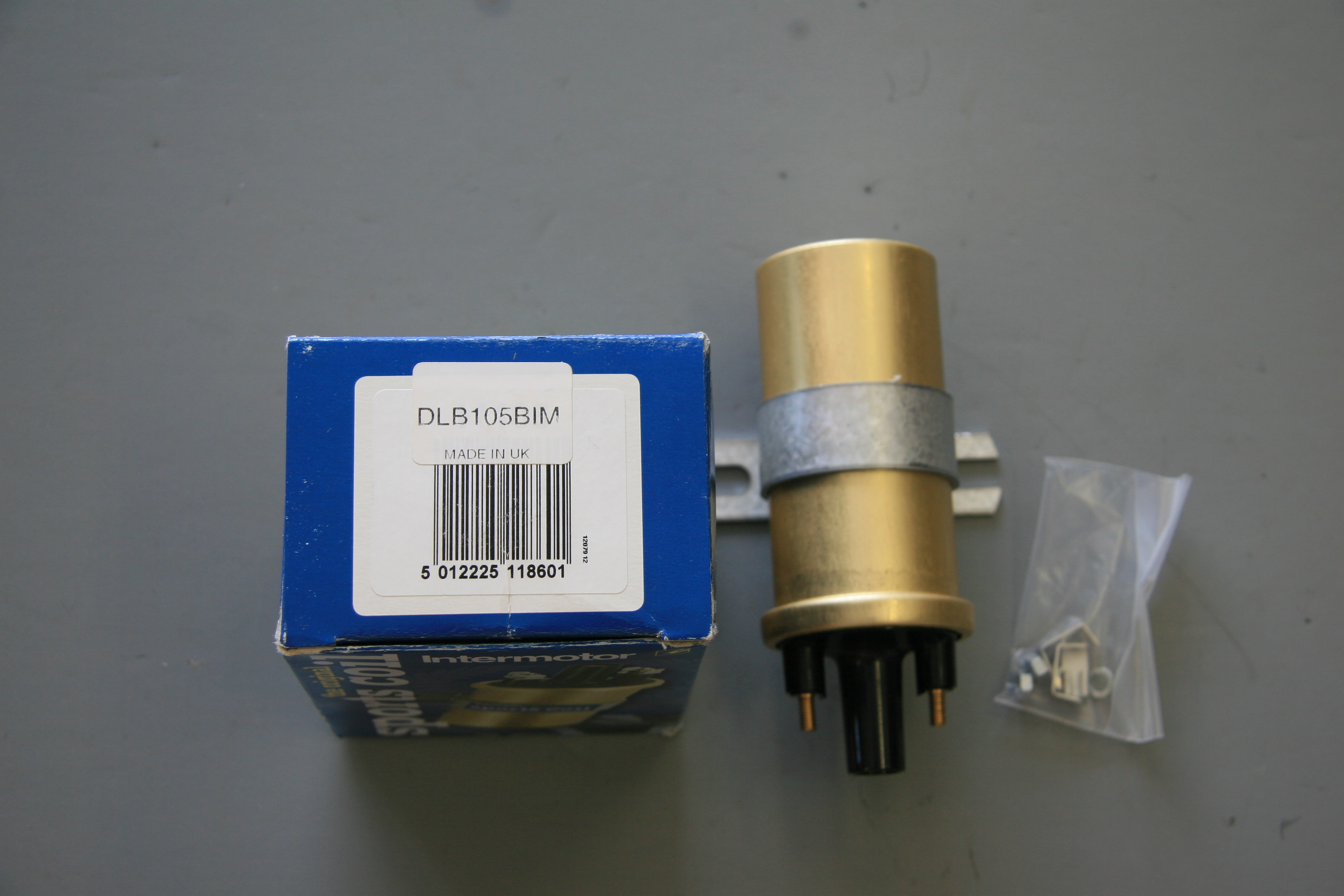
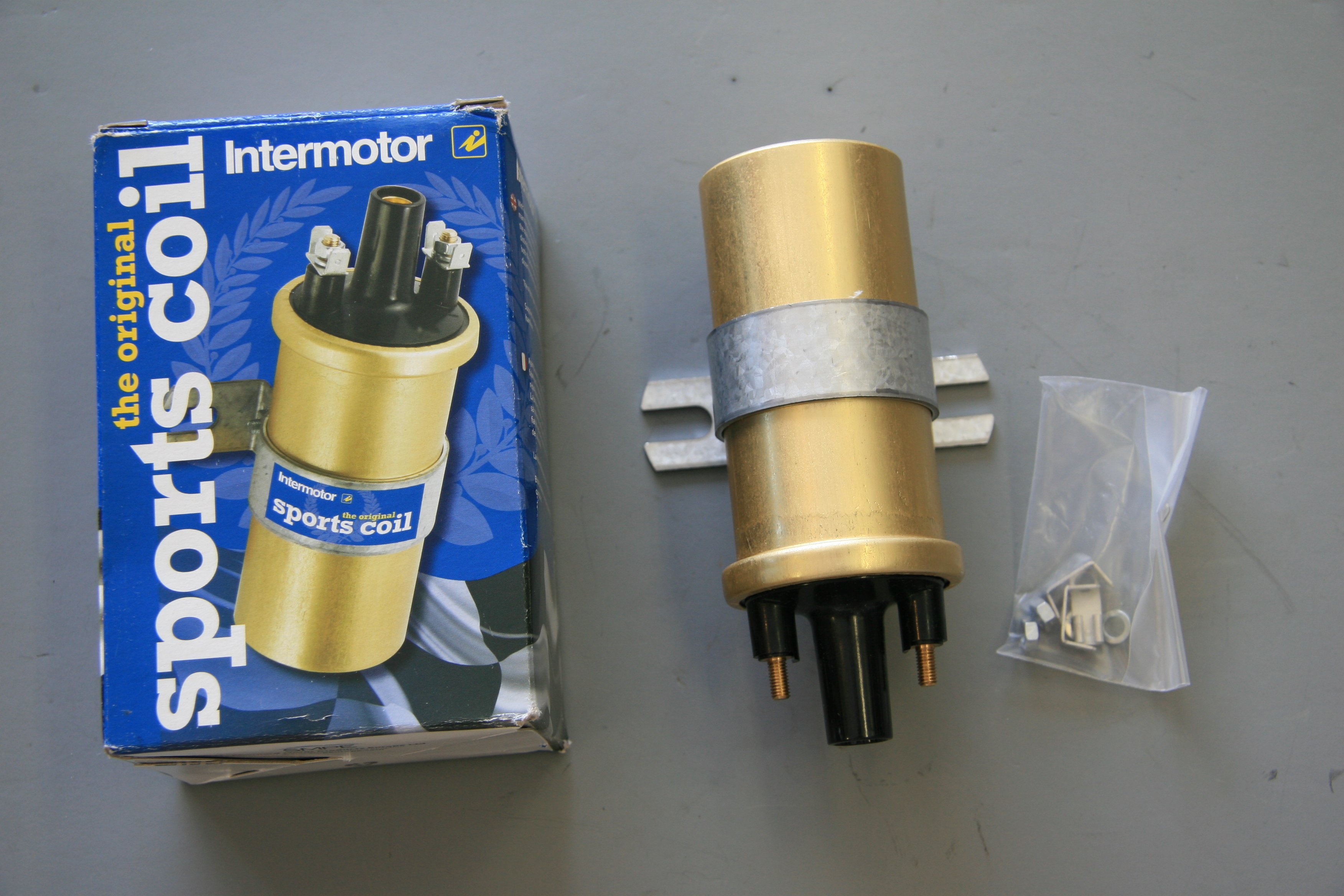
Coil
I also ordered the coil recommended by Classic Jaguar as an upgrade for the original unit. It was available for $35.00. It is an Intermotor Sports Coil.
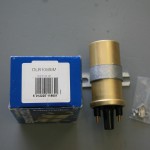
Intermotor Sports Coil
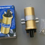
Intermotor Sports Coil
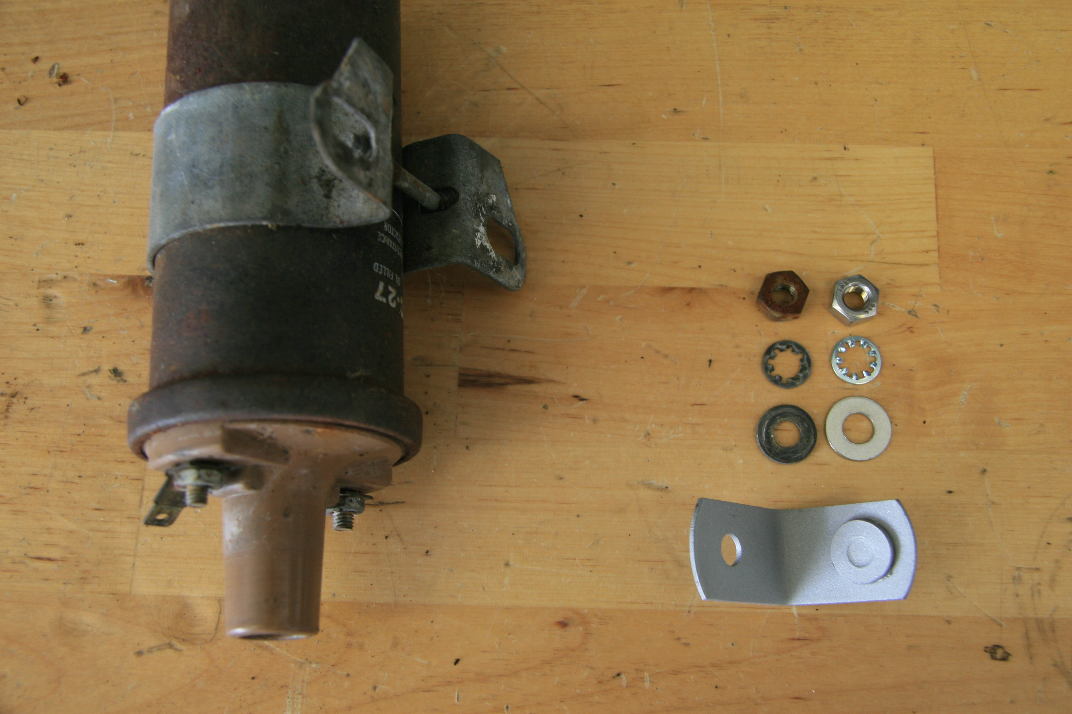
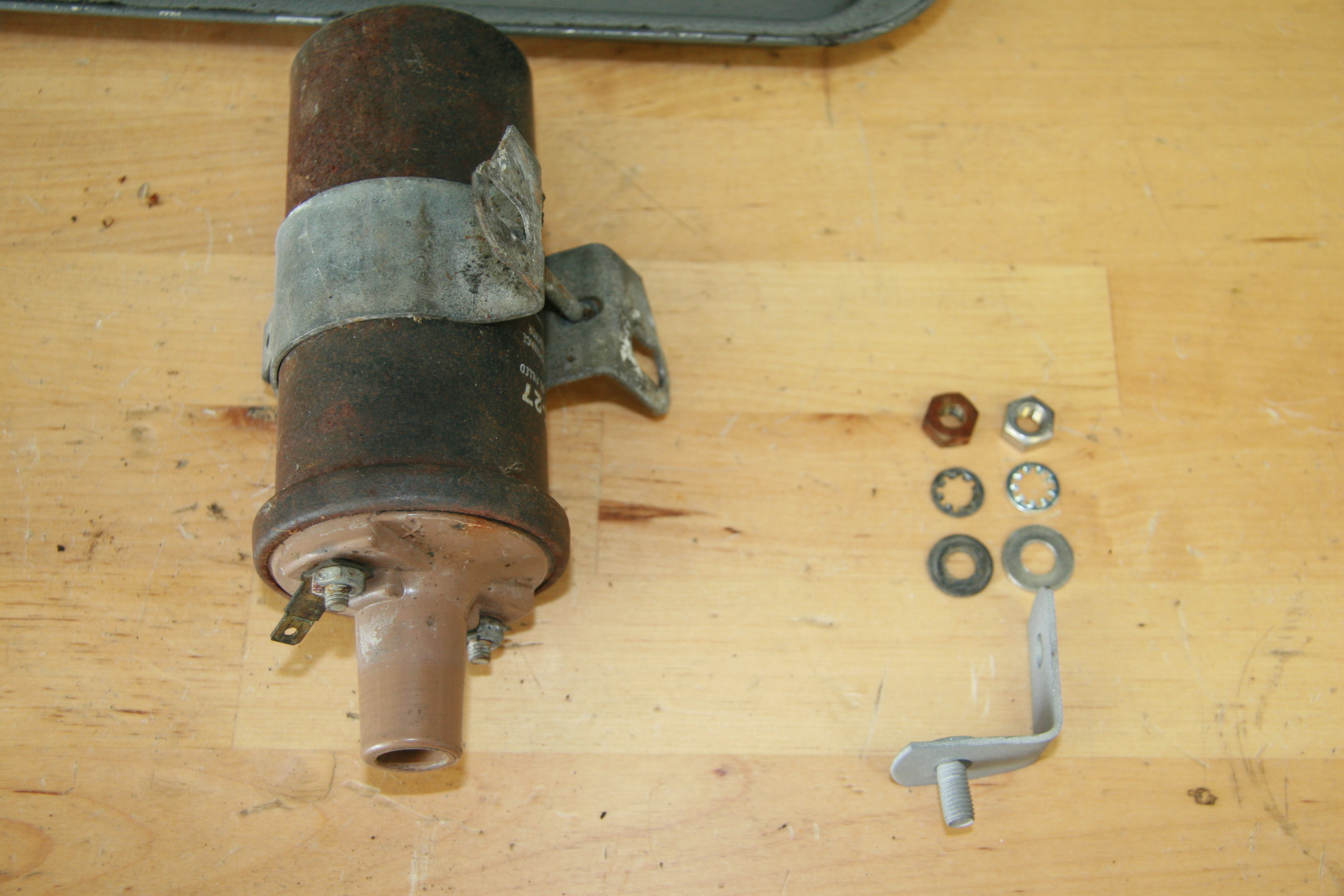
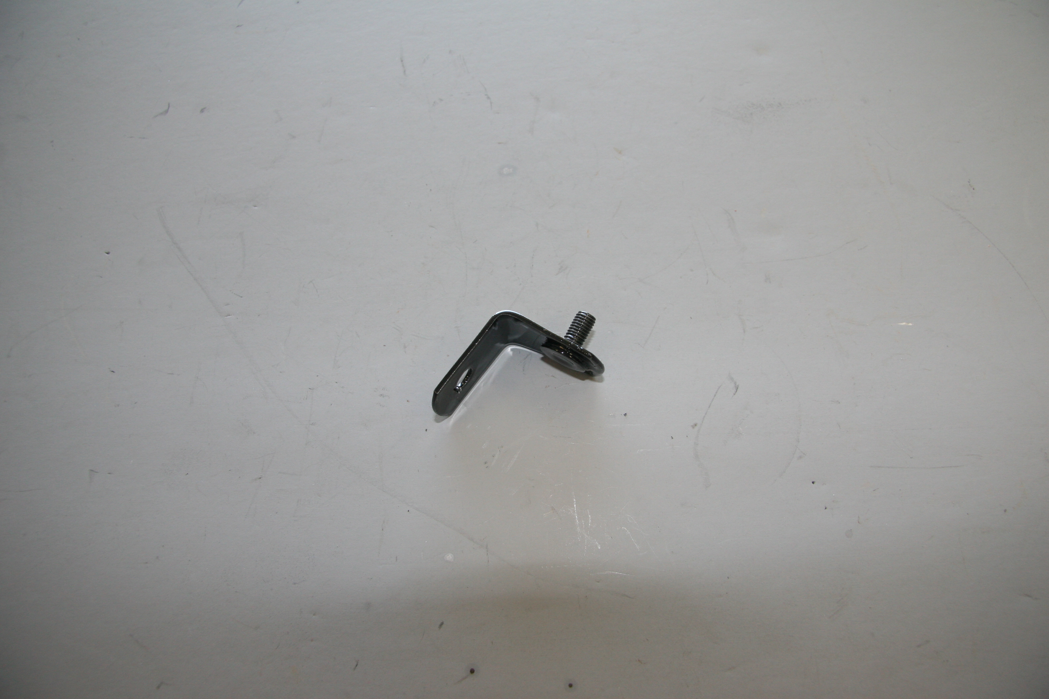
Extension Assembly for Coil Bracket
There is a small bracket that mounts to the coil bracket that is used to attach the coil to the front of the cylinder head.
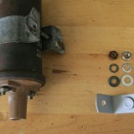
Coil Extension
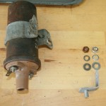
Coil Extension
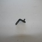
Bracket Extension
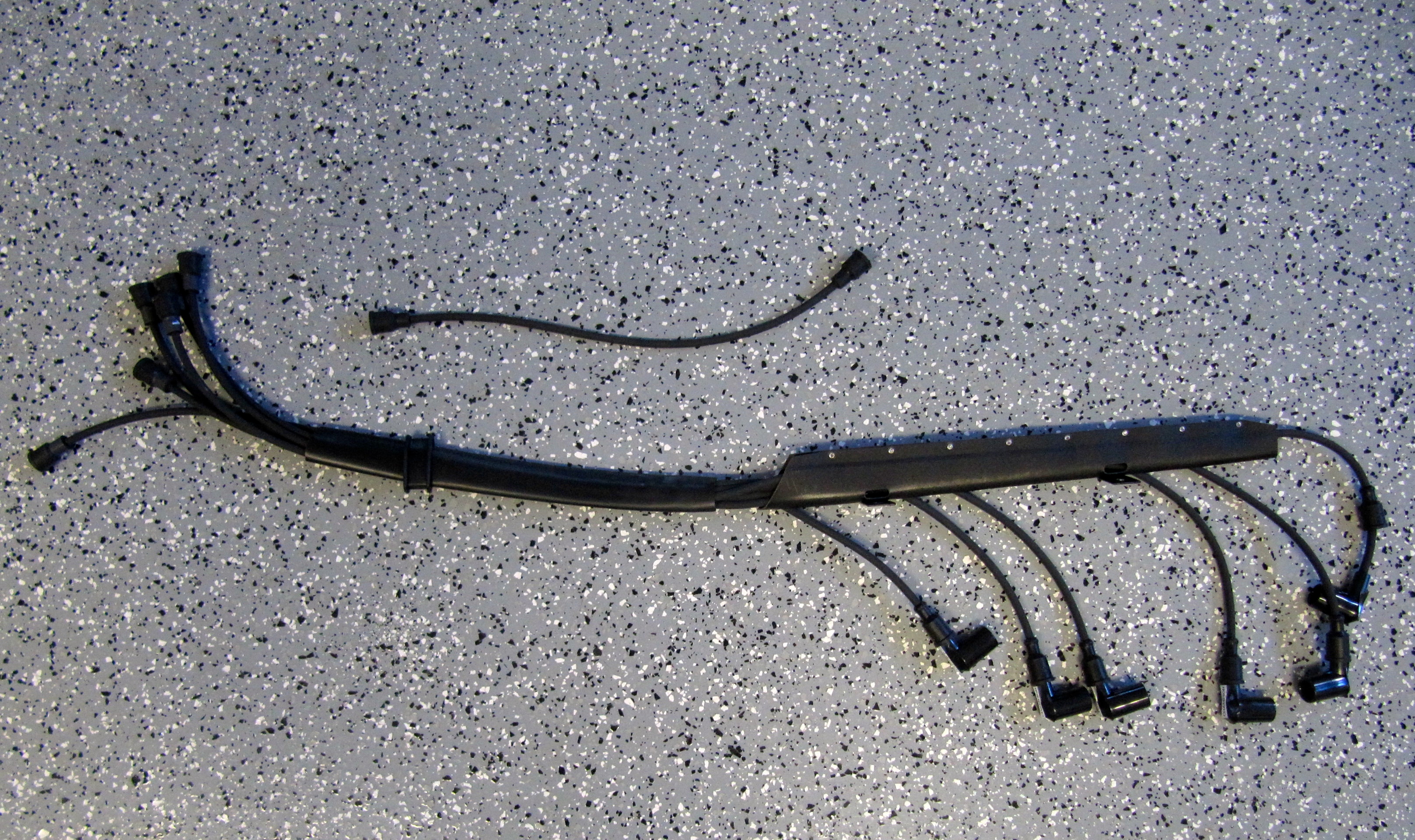
Ignition Wiring
Xks Unlimited fabricates an ignition wiring loom with Petronix wiring and press on leads for the cap of the 123 distributor. While expensive, the loom will result in a neat package across the top of the motor.
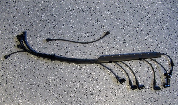
Pertronix Ignition Wiring Loom