
Original Interior
The original interior was medium red with black piping using leather and matching “leathercloth” vinyl. Carpet was also red and black armacord finished the boot interior. An adjustable plastic 16 1/2” steering wheel was standard.
Interior Modifications
Upholstery and Carpet
The interior finish materials were supplied by Heritage Trim. http://www.heritagetrim.com/. While somewhat expensive and not particularly fast on delivery, they provide a premium product with top grade materials. As the images show, I decided on black leather upholstery with red piping. Although I would have preferred a brighter red material for the piping, I was quite pleased with Heritage Trim.
Heritage also supplied the carpet, and while a material very close to the original is available, I decided to go with Wilton Wool which is a softer cut pile and to my view a more elegant look.

Heritage Interior
Steering Wheel
The Steering Wheel was replaced with a Moto-Lita wheel made of mahogany wood. It is ordered with a complimentary hub so that the original control head (trafficator) and horn button may be used.

Moto Lita Wheel
Fiberglass Gearbox Cover
Using a Toyota five speed gearbox required relocating the hole for the shifter in the gearbox cover from the original side mount to a center location. A fiberglass cover is available from http://www.britishcarspecialists.com/. The fiberglass cover is lighter, cooler as it does not conduct the heat like the original metal cover, and was easy to modify. I covered the gearbox cover with Dynamat Extreme and an additional layer of aluminum duct insulation to keep things cool.

Fiberglass Gearbox Cover
Interior Insulation
Anyone who has ever driven a stock Healey knows that the interior, particularly in the footwells, can get quite toasty but the combination of sealing firewall holes and installing modern insulation materials can virtually do away with the cockpit heat. I used Dynamat Extreme in the Bloody Beast and then installed a layer of aluminum backed foam duct insulation used in home HVAC systems on top of the Dynamat. All gaps between the pieces of insulation were covered with aluminum tape.

Dynamat Extreme

Aluminum Interior Insulation
Tilted Driver’s Seat
Big Healeys have reasonable legroom for those of us who are over six feet tall, but the designed seating arrangement places the driver very close to the steering wheel. One way to improve on the situation is to add spacers of varying lengths to the studs on the seat rails. The effect is to create a slight rearward tilt to the seat that then permits a little more arm extension for driving. I just picked up the extensions at the local hardware store.

Tilted Seat
Cup Holder
While I do not permit any beverages in the Bloody Beast other than water, the good ol’ American cup holder is a convenient accessory to the Healey interior. I borrowed the idea from Roger Conte – Ausmhly rfc_2002@sbcglobal.net. I used a Volkswagen Jetta cup holder #1J0 858 601D and mounted it under the parcel tray. Works like a charm and virtually hidden when not in use. This link will navigate you to the detail page on the cup holder: https://valvechatter.com/?p=3487

Cup Holder Empty
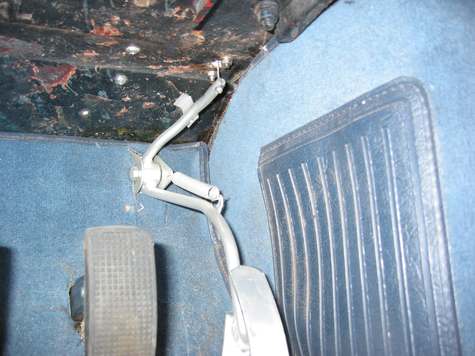
Alloy Pedal Covers
Just to dress up the pedals a bit and to provide an improved pedal surface, I installed alloy covers on the original pedals. My brake and clutch pedal covers were custom made and a gift from buddy Mick Nordquist, while the accelerator pedal came from Denis Welch Motorsport http://www.bighealey.co.uk/content/wider-accelerator-pedal.

Alloy Pedal Covers
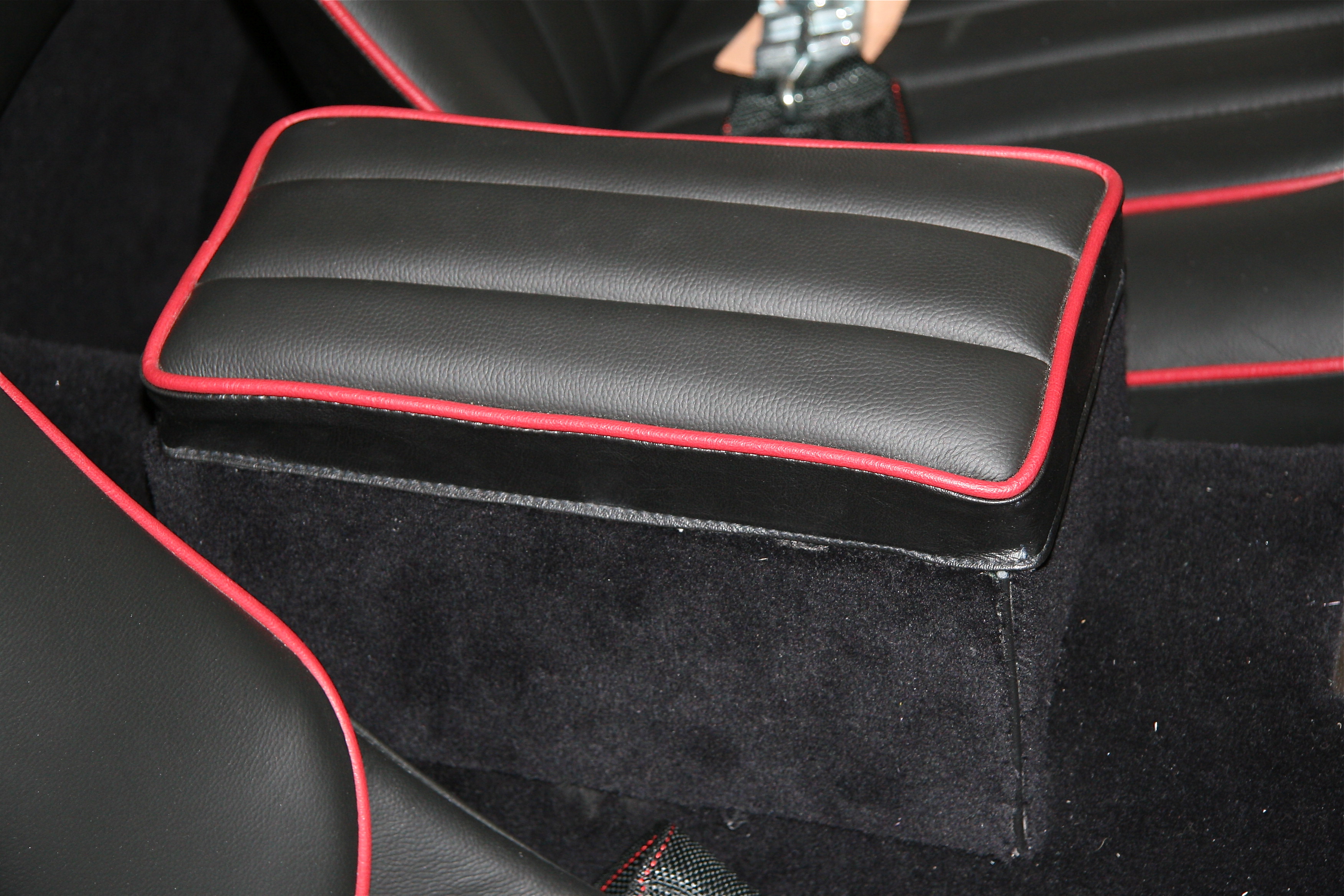
Arm Rest/ Console
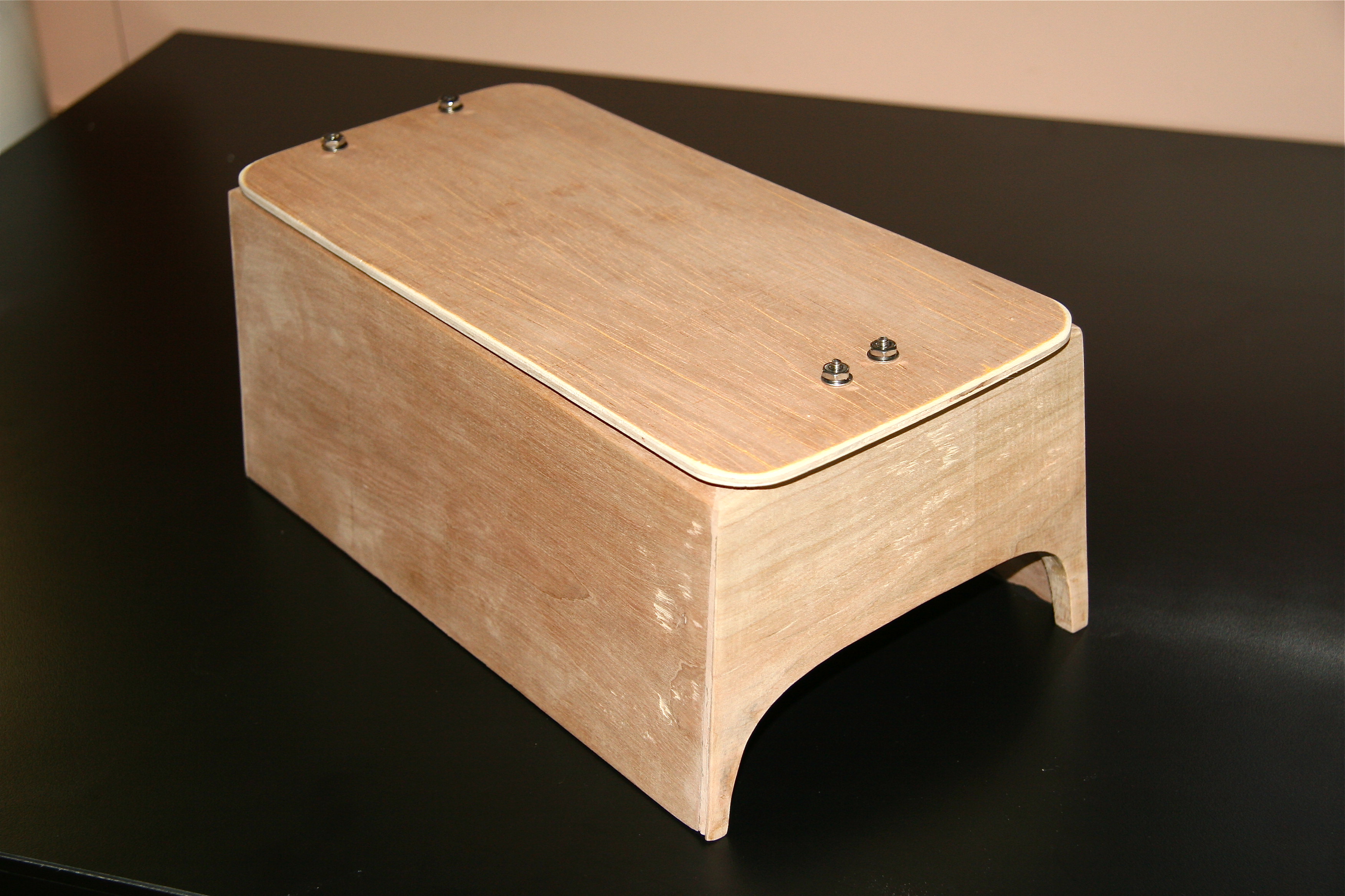
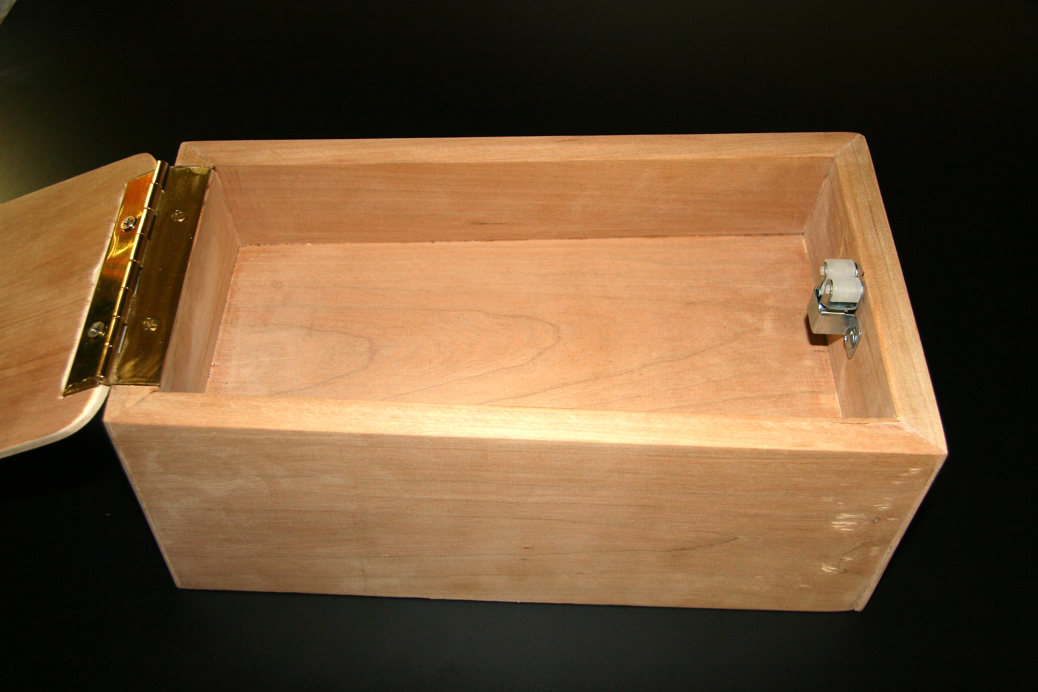
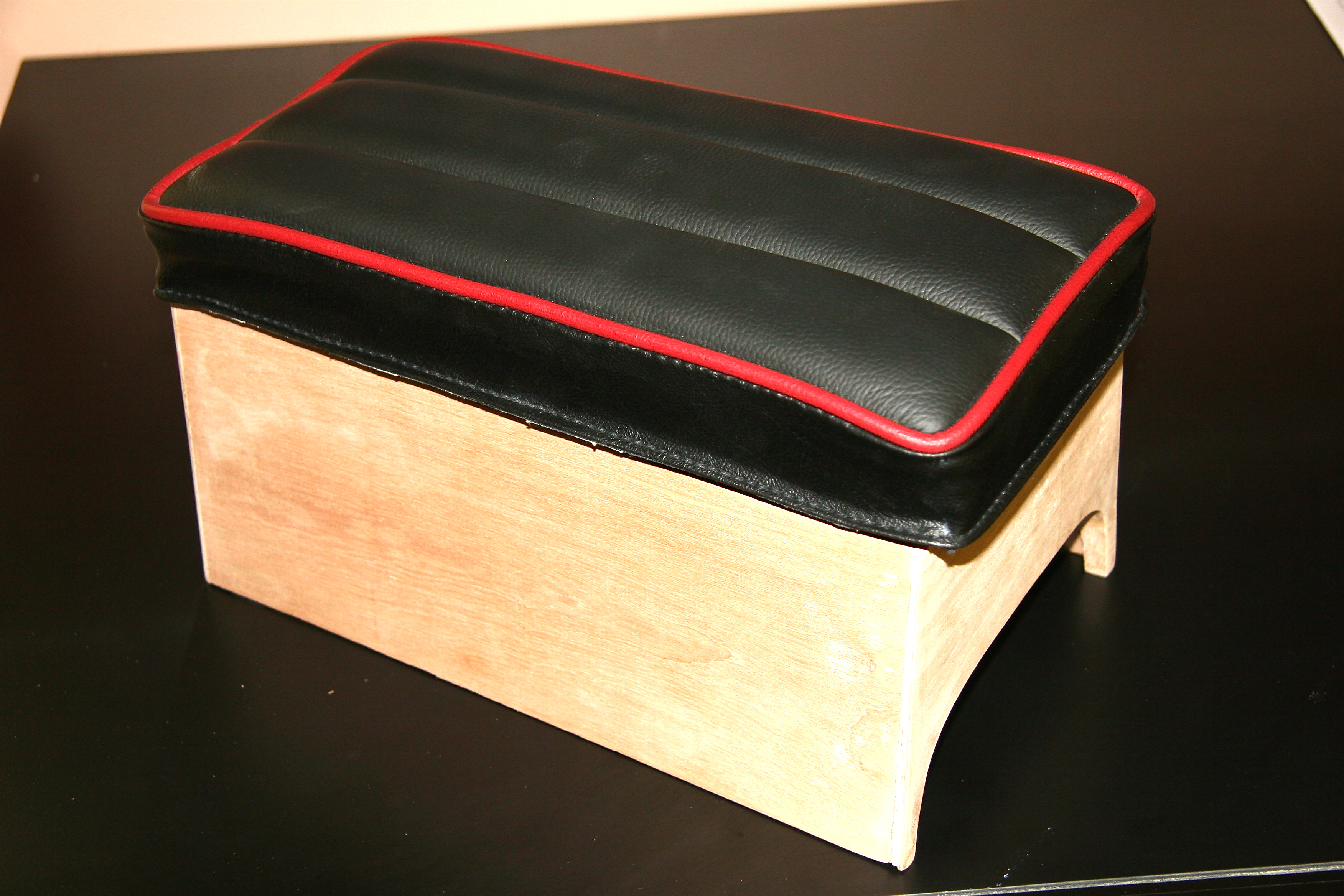
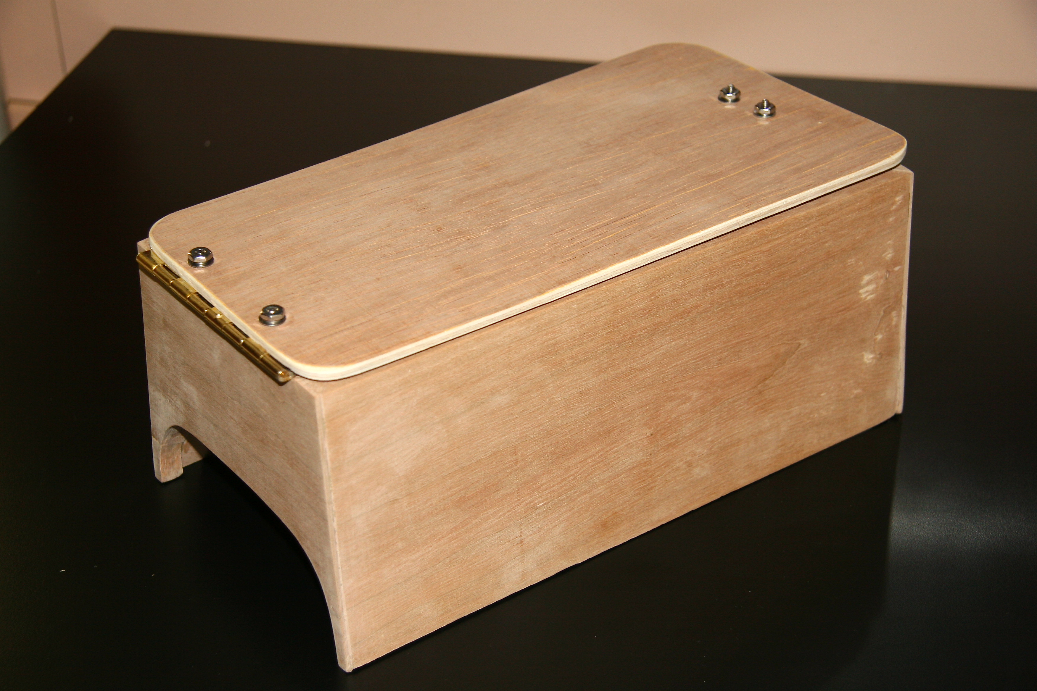
The padded arm rest provided as original equipment in the MK1 interior, while attractive in appearance, was pretty useless in that it was too low for one to actually rest an arm on the pad while driving. I decided to use the cushion as supplied by Heritage Trim to fabricate the top of a box or console to be installed on the gearbox/propshaft tunnel.
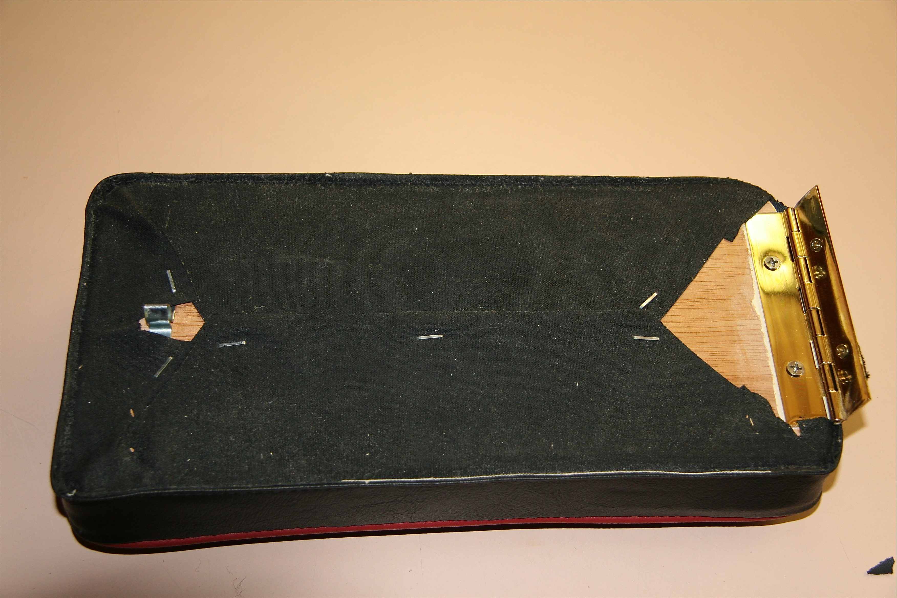
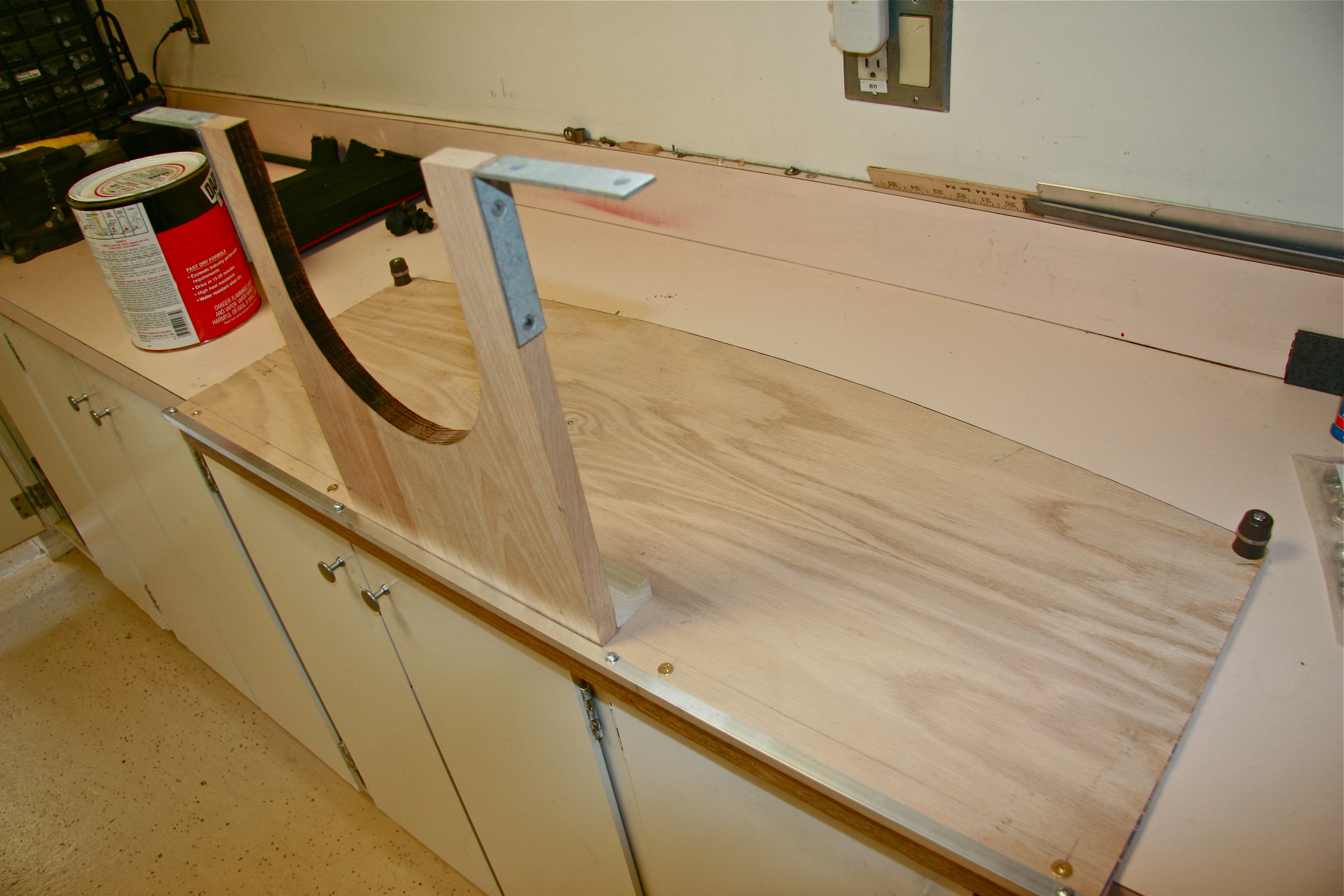
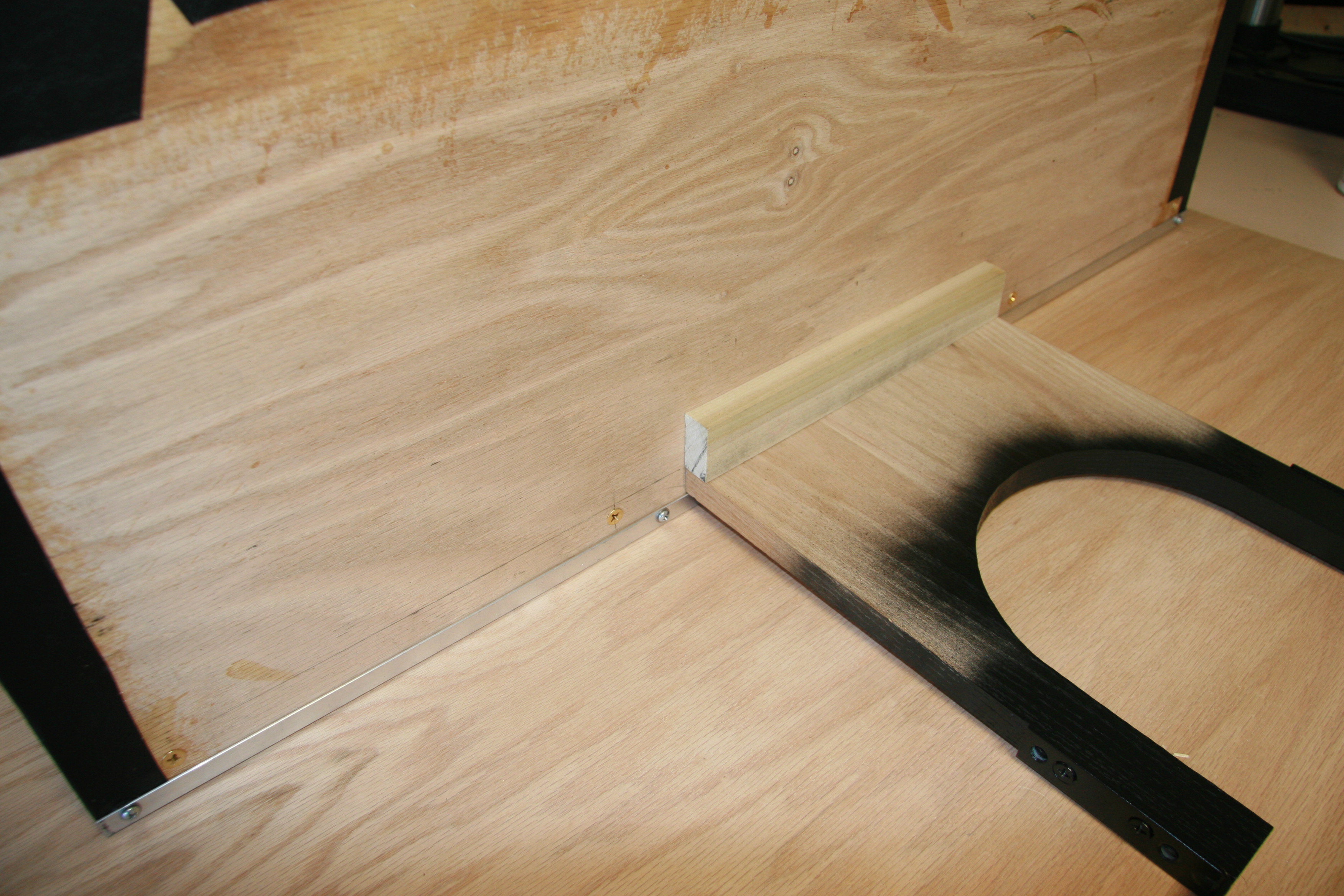
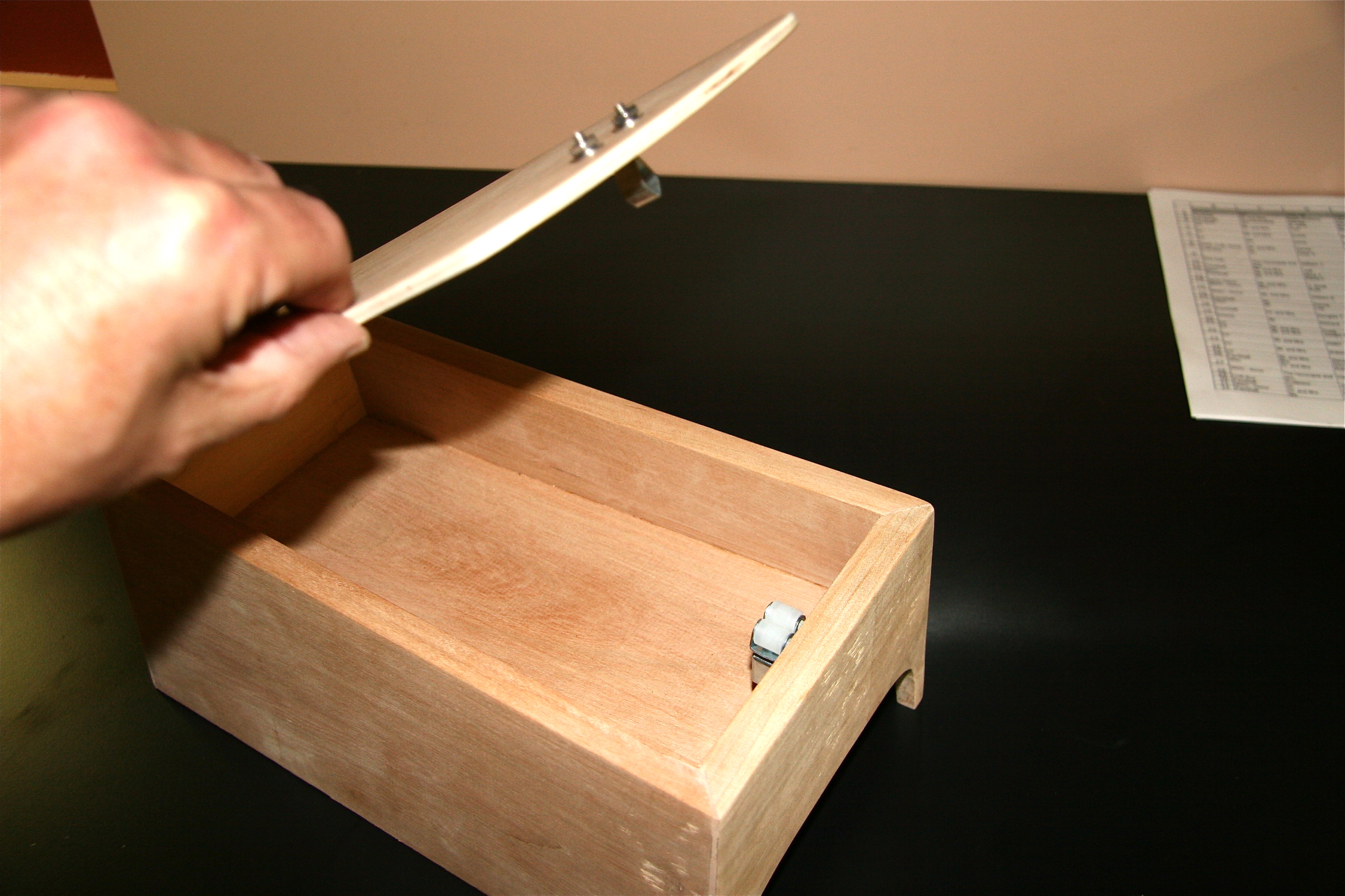
I began to form my idea for the console by fitting a cardboard shoebox to what I considered to be ideal dimensions, and then built a wooden box to provide some storage along with a fully functional arm rest. I encountered the need for lots of weird angles, but eventually got it all worked out and was very pleased with the outcome. After hinging the top, I covered the box in the wilton wool carpet and created something that appears original to the untrained eye. I could have permanently mounted the box to the tunnel but chose not to do so. This allows me to reposition the arm rest as desired.

Console Installed
Console Box

Console Box
Console Interior
Console Box
Console Lid
Console Installed
Rear Luggage/Parcel Shelf
MKIII owners have a nice luggage shelf behind the front seats if they need more storage space, but MKI owners didn’t have that convenience. Inspired by my upcoming cross-country trip, I decided to bold my own. The shelf is completely removable, but alas, unlike the BJ8 owner, I cannot just fold my up and out of the way. In my case, I either travel with it, or without it. This is the link to assembly directions and more images: https://valvechatter.com/?p=3508

Luggage Shelf

Luggage Shelf
Luggage Shelf
Luggage Shelf

Luggage/Parcel Shelf Image 6
Spare Tire Cover
While not technically the “interior,” I wanted to dress up the boot for appearance purposes nut also to protect clothes or other objects place in the boot that would have been exposed to a spare tire. I had a local upholstery shop sew a cover for me. I then cut a slot in the rear for the hold-down strap and I was in business. It makes for a much cleaner look in the boot.

Spare Tire Cover


