New Vinyl Door Piping and Ignition Wiring

Two more little jobs need to be accomplished in my journey to “renew” the Healey:

Vinyl Door Piping

After a little over ten years of use, the vinyl piping that edges the aluminum trim plate on the passenger side door shut face pillar was just worn out. My rear door gap is a little tight and the vinyl piping sometimes gets caught as the door closes.

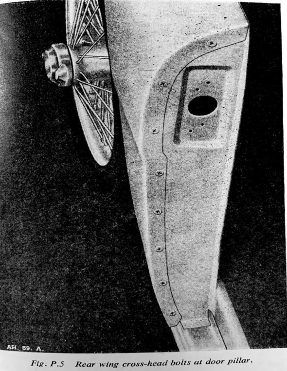
According to Anderson and Moment’s book, Austin-Healey Restoration Guide, the bottom and rear door sills were covered with aluminum trim plates, textured in a raised pattern. A vertical section covered the shut face pillar, secured to the pillar with eight chrome Phillips screws, 54K3024, #28 in the illustration.

Shut face Pillar

Black grained vinyl piping separated the rear trim plate from the rear fender along the door opening. This piping extended up and over the trim panel with its core removed so that it wouldn’t catch on the edge of the door when opened and closed.

From the Concours Guidelines: From the introduction of the Abingdon BN6 through possibly the end of BJ7 production, the shut facing was fastened with small, #4 truss-headed Phillips screws with very small cross- head screwdriver slots. Starting around 1963 or 1964 the screw head was changed from Phillips to Pozidriv. 

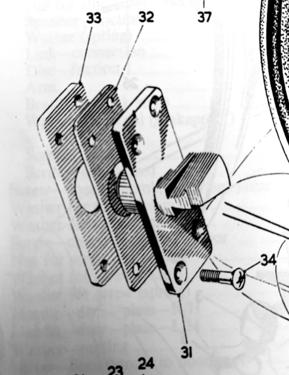
To remove the aluminum trim plates, one must remove the door lock striker, 14B2841, #31; that is attached through the door shut face pillar and packing plate, 14B2842, #32, into a tapped plate, 14B2843, #33. The assembly is secured with four chrome Phillips Head striker fixing screws, RMP0312, #34 (#10 x 3/4”)

Door Striker Assembly

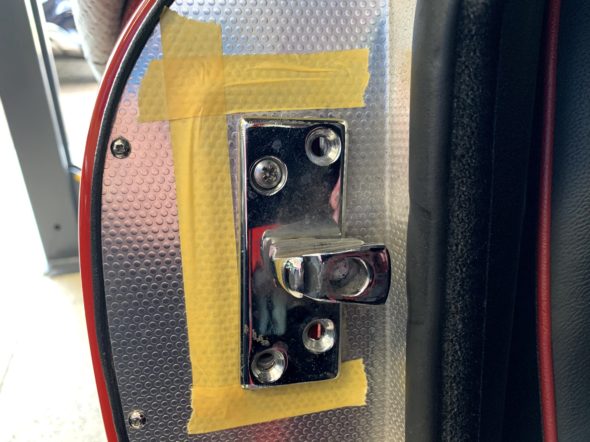
The striker assembly is adjustable so to be sure to return the assembly to the same position once reassembled, tape was used to mark the outside edges of the striker on the aluminum trim plate.

Marked Position of Door Striker Before Removing the alloy trim

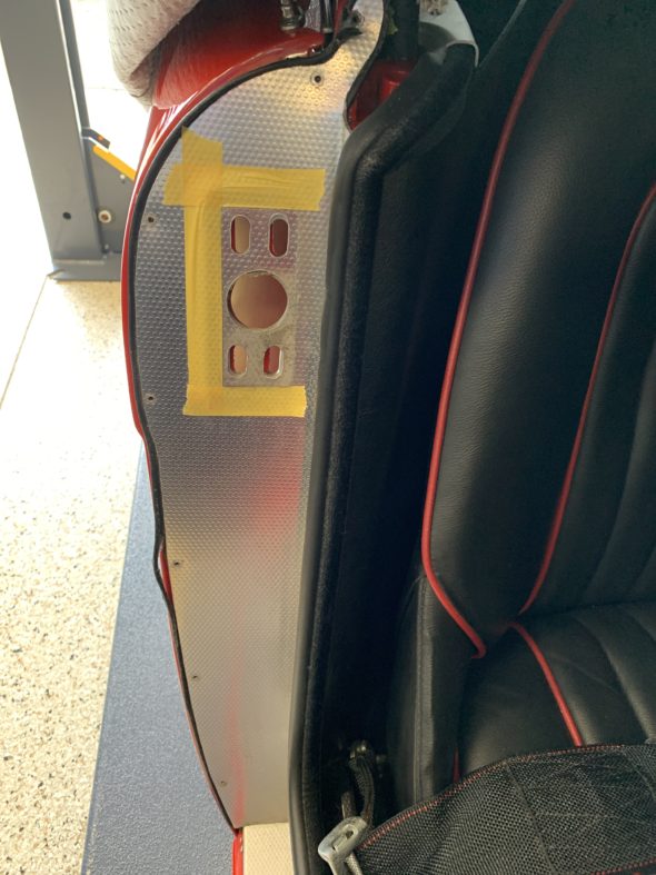
I removed the striker plate assembly by loosening the 4 Pozi Drive screws.

Door Lock Striker Removed

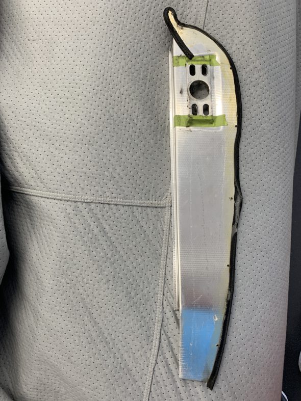
I then removed the seven #4 Phillips head screws that secure the aluminum trim plate to the door shut face pillar. The trim plate could then be removed. The image below shows how the piping is glued with contact cement to the trim plate before reinstalling.

Reverse Side of Alloy Trim Plate

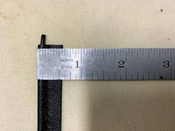
Geoff Chrysler, owner of Rightway Heritage Trim, made a pair of the piping pieces for me that are the proper size.

Chrysler Vinyl Trim

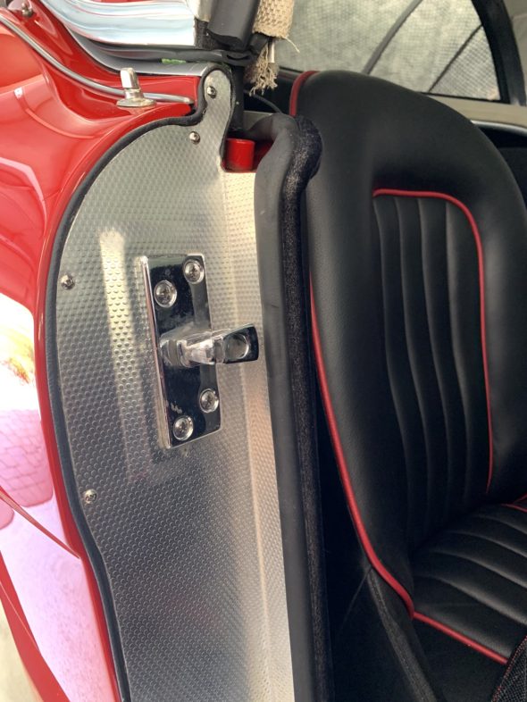
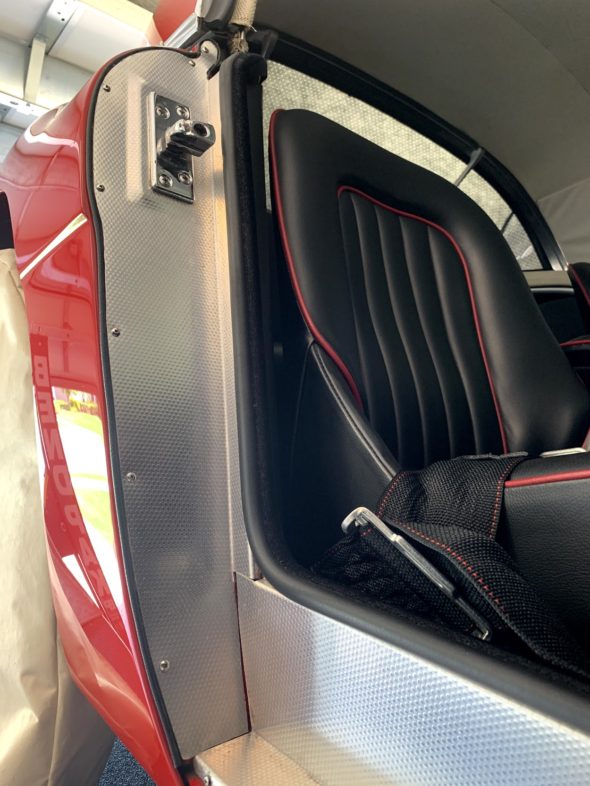
I glued the piping to the plate and then remounted the plate on the pillar. The turn at the top of the trim plate is difficult to address and it does take some patience. This is the finished product reinstalled on the car.

Vinyl Piping on Door Shut Face Pillar Alloy Trim

Vinyl Piping on Door Shut Face Pillar Alloy Trim

Ignition wiring

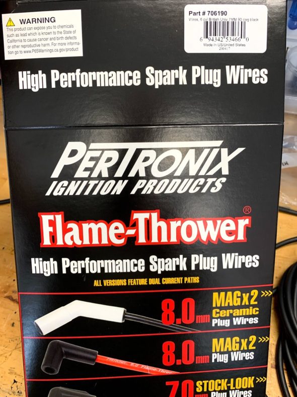
The ignition wiring for the coil, distributor and spark plugs was operating perfectly but I thought as a preventative maintenance item I would go ahead and replace the wires so I would be good for another ten years. This included replacing the distributor cap and rotor on the 1-2-3 electronic ignition device. I used the same type of wiring installed on the car when it was restored. The product is made by Pertronix and is designed for use with electronic ignition systems.

Pertronix Spark Plug and Coil Wires

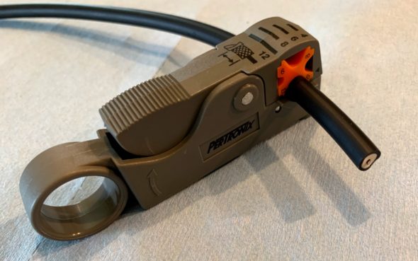
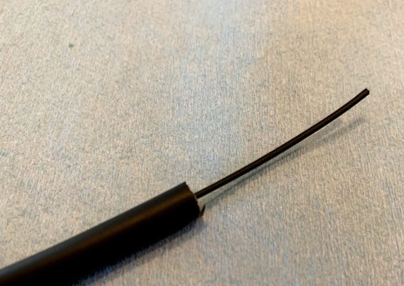
As supplied, the spark plug terminals and boots are already mounted on the individual wires. One only needs to cut the wires to length and install the terminals and boots for the distributor end of the wires. To make the job a little easier I used a wire/insulation cutter made by Petronix for the task. It works perfectly and leaves a nice clean core to wrap around the terminal.

Pertronix spark plug wire Insulation stripping tool

New Spark Plug Wire Trimmed

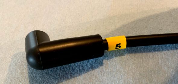
I also installed heat shrink wire numbers on the wires to help with sorting the wires.

Pertronix Spark Plug Wire Boot and Number

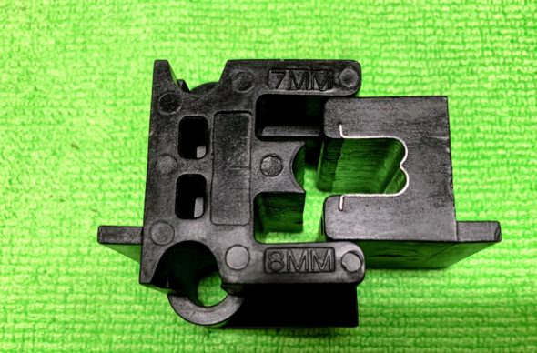
Pertronix also sells a two piece crimper used to crimp ignition wire terminals to the cable. It works for 7mm and 8mm wires, and produces perfect crimps every time. One places the terminal and wire between the two pieces of the device and then tightens them together in a vice.

Ignition Wire Crimper

All the new products were installed and the car is running just fine.


Assorted Ignition Modifications

The Original Ignition System

Distributor: Lucas DM6A

Coil: Lucas HA 12 volt

Spark Plugs: Champion UN12Y

Modified Ignition System

Distributor

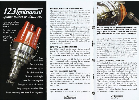
Having converted the Bugeye to electronic ignition with a Crane system, I knew that I wanted to use electronic ignition with the Bloody Beast, but unlike the Crane system, I wanted to use a system that would be housed in the distributor such as a Pertronix. After doing some research I decided to replace the entire distributor with a newly introduced Dutch product, the 123 Distributor. The United States distributer is https://123ignitionusa.com

More information about the installation is provided in this website post: https://valvechatter.com/?p=12431

One appealing aspect of the 123 is that the advance curve is determined by simply adjusting the settings by turning an adjustment on the outside of the distributor and “clicking” it into place. Sixteen curves are available from which to select. Since my purchase the vendor has introduced a programmable bluetooth distributor that can be managed with a laptop. The model number of the unit I used is 123/GB-6-R-V.

For initial set-up, I chose the recommended “B” setting. While the distributor is a “drop-in” in for the BJ8 with an electronic tach, a kit is supplied to adapt it for the mechanical tach drive of the BT7. The shaft did need to be drilled and the drive dog from the original Lucas unit installed with a few spacing washers. My unit was supplied by a German vendor Brits’N’Pieces.

123 Distributor

123 Distributor

Coil

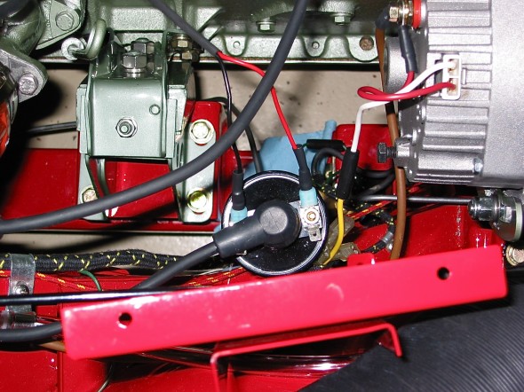
Rather than the original Lucas Coil, or Lucas Sports coil, I decided to go with the Pertronix Flame Thrower Coil in the Bloody Beast. The coil was originally mounted on top of the generator, but since I am using an alternator, that mounting position was not available. I mounted the coil on the vertical upright shroud support post.

Pertronix Flame Thrower Coil

Pertronix Flame Thrower Coil

 Ignition Wiring

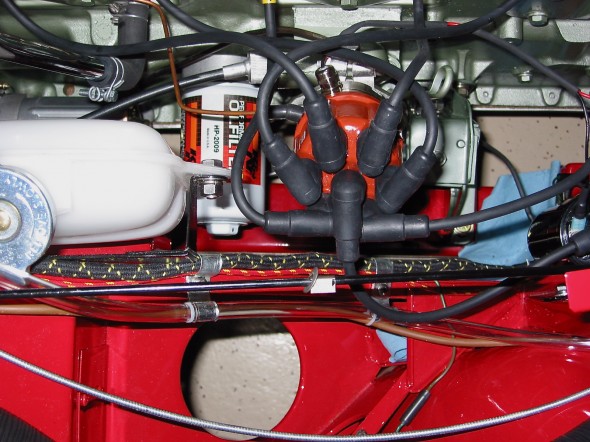
To complement the Pertronix Flame Thrower Coil, is used Pertronix ignition wiring as well.

Ignition wiring

Ignition wiring


cvcvbvcb

Ignition

Spark Plugs

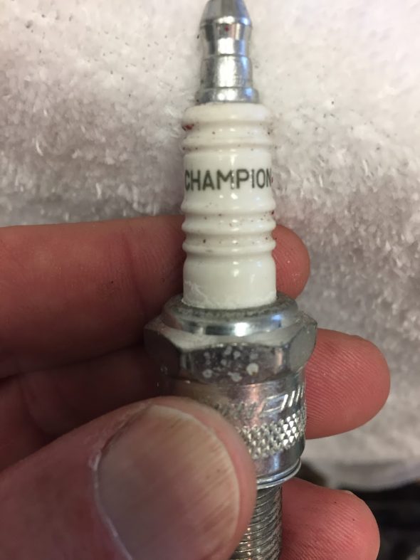
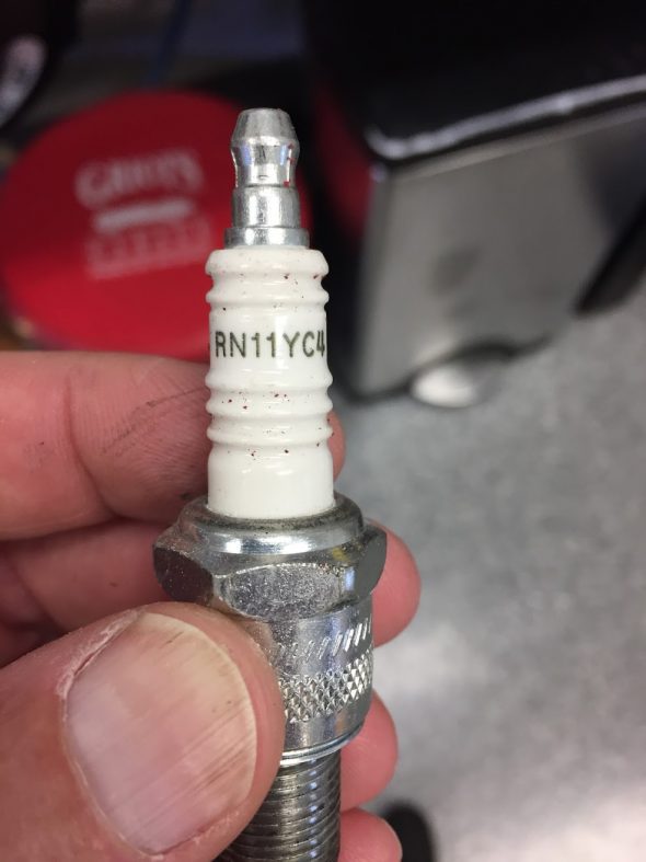
I don’t know if I will stick with the Champion plugs or not, but Mike Gassman installed Champion RN11YCA plugs when the engine was rebuilt and they remain in the engine at this point.

Champion Spark Plug Jag MK2

Champion Spark Plug RN11YC4 Jag MK2

Distributor

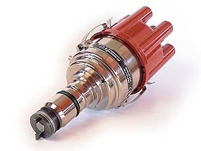
There are several options available for upgrade to an electronic ignition. I used a 123 Electronic Distributor on my 1960 Austin Healey 3000 and was very pleased with the installation so I ordered the same distributor designed for the Jaguar XK motor – negative ground. The company that produces the distributor is located in the Netherlands. This is the link to their website: http://www.123ignitionusa.com/jaguar.html.

I ordered the “Jag 6-R-V” from Classic Jaguar, 9916 Hwy 290 West, Austin, TX 78736     (512) 288 8800 Austin, TX. http://classicjaguar.com/cj/ign_sys.htm for $425.00.

This web site provides some useful commentary on the 123 distributor, although it should be clear that I am using the Jag specific model, not the generic british model.

http://jaguaretype.wordpress.com/home/technical/123-distributor/

123 Distributor

123 Distributor


Directions for Installation Provided with the Distributor

WITH THE OLD DISTRIBUTOR STILL IN PLACE

1. Mark the output towards cylinder #1 on the cap.

Remove the low voltage cable from the distributor to the coil, and remove the cap.

Now ask someone to crank the starter, and make a note: is the rotor rotating clockwise (CW) or is it rotating counter-clockwise (CCW)?

2. Crank the engine in its normal direction until you see that the rotor points toward the mark you made for cylinder #1, and verify that the static timing-marks of your engine align.

Do not rotate the engine anymore!

3. Check the firing order of the cylinders.

Use your workshop manual, or follow the cables from the cap to the spark plugs.

You start with cylinder #1, and remember to count in the direction that you have found earlier.

Make a note of the firing order, too. E.g. ‘1-4-2-6-3-5.’

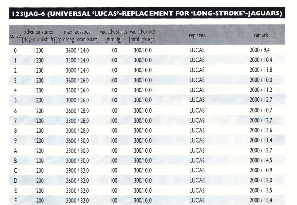
4. Check which advance-curve is required for your engine. Use your workshop manual, check the model number of the existing distributor. Also compare the curve-listings for the various models in this manual.


OUT WITH THE OLD DITRIBUTOR, IN WITH THE 123 IGNITION!

5. Turn the ignition off, and (with the engine still in the static position for cylinder #1) and remove the old distributor.

6. Using an 8mm Allen wrench, open the cap at the side of the 123 Ignition. Rotate the micro-switch to select the proper advance curve using a small screw driver. Close the cap tightly.

123 Ignition JAG-6 Curves

123 Ignition JAG-6 Curves

7. Mount the unit carefully, and ensure that the drive-dog mates correctly. Find a position so that the vacuum nipple and cables come out conveniently. Fasten it in such a way, that you can still rotate the new distributor.

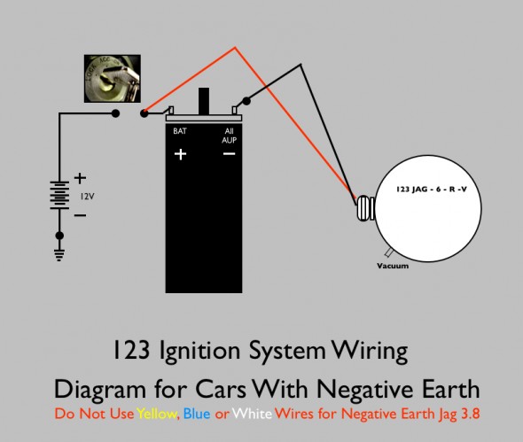
8. Follow the appropriate wiring diagram on the last two pages of the manual, but leave the black wire unconnected for now.

9. Turn the ignition on. A timing LED shines through one of the six holes in the aluminum disc. Rotate the body until the LED is “off.”

Now slowly rotate the body OPPOSITE to the direction that you have found under point 2, until the green LED just lights up. While turning the body, also press the rotor in the same direction to remove any free-play in the drive gear. Now, tighten the 123 Ignition securely.

10. Connect the black wire to the coil. Connect the spark plug leads in the proper sequence to the new cap (see point 4), starting with cylinder #1, to which the new rotor is pointing. Also connect the high voltage lead from the coil to the center position of the cap. Attach the cap to the 123 Ignition. Keep low-voltage wiring well away from the high-voltage cables and from moving parts. Do not connect the vacuum tube yet.

123 Ignition Wiring Diagram

123 Ignition Wiring Diagram

11. You can now start your engine. Use a stroboscope to adjust the maximum advance for your engine. If that is correct, you can attach the vacuum-tube to the nipple of the 123 Ignition with the ‘V’ option.

Coil

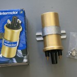
I also ordered the coil recommended by Classic Jaguar as an upgrade for the original unit. It was available for $35.00. It is an Intermotor Sports Coil.

Intermotor Sports Coil

Intermotor Sports Coil

Intermotor Sports Coil

Intermotor Sports Coil


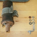
Extension Assembly for Coil Bracket

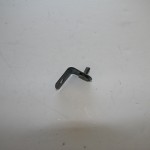
There is a small bracket that mounts to the coil bracket that is used to attach the coil to the front of the cylinder head.

Coil Extension

Coil Extension

Coil Extension

Coil Extension

Bracket Extension

Bracket Extension


Ignition Wiring

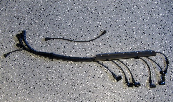
Xks Unlimited fabricates an ignition wiring loom with Petronix wiring and press on leads for the cap of the 123 distributor. While expensive, the loom will result in a neat package across the top of the motor.

Pertronix Ignition Wiring Loom

Pertronix Ignition Wiring Loom