Doors and Windows

Doors and Windows

Door Hinges

I decided against removing the hinge pins to “restore” the hinges. All the hinges were free moving but nice and tight with no discernible excess play. The door side of the hinge is aluminum while the body pillar side of the hinge is unpainted steel. It appeared that the hinges were painted while mounted on the car.

I removed the paint with paint remover, painted the bare metal side of the hinge with silver POR-15 (since I was leaving the hinges assembled, I could not zinc or cad plate the bare metal pieces), greased the hinges and tried them all for good fit with new bolts and screws sourced from SNG Barratt.

All of the adjustment in the door hinges is on the door side mounting. The hinges are fixed in place by captive nuts in the “A” and “B/C” pillars.

The hinges are now ready for assembly to the car when the time comes.
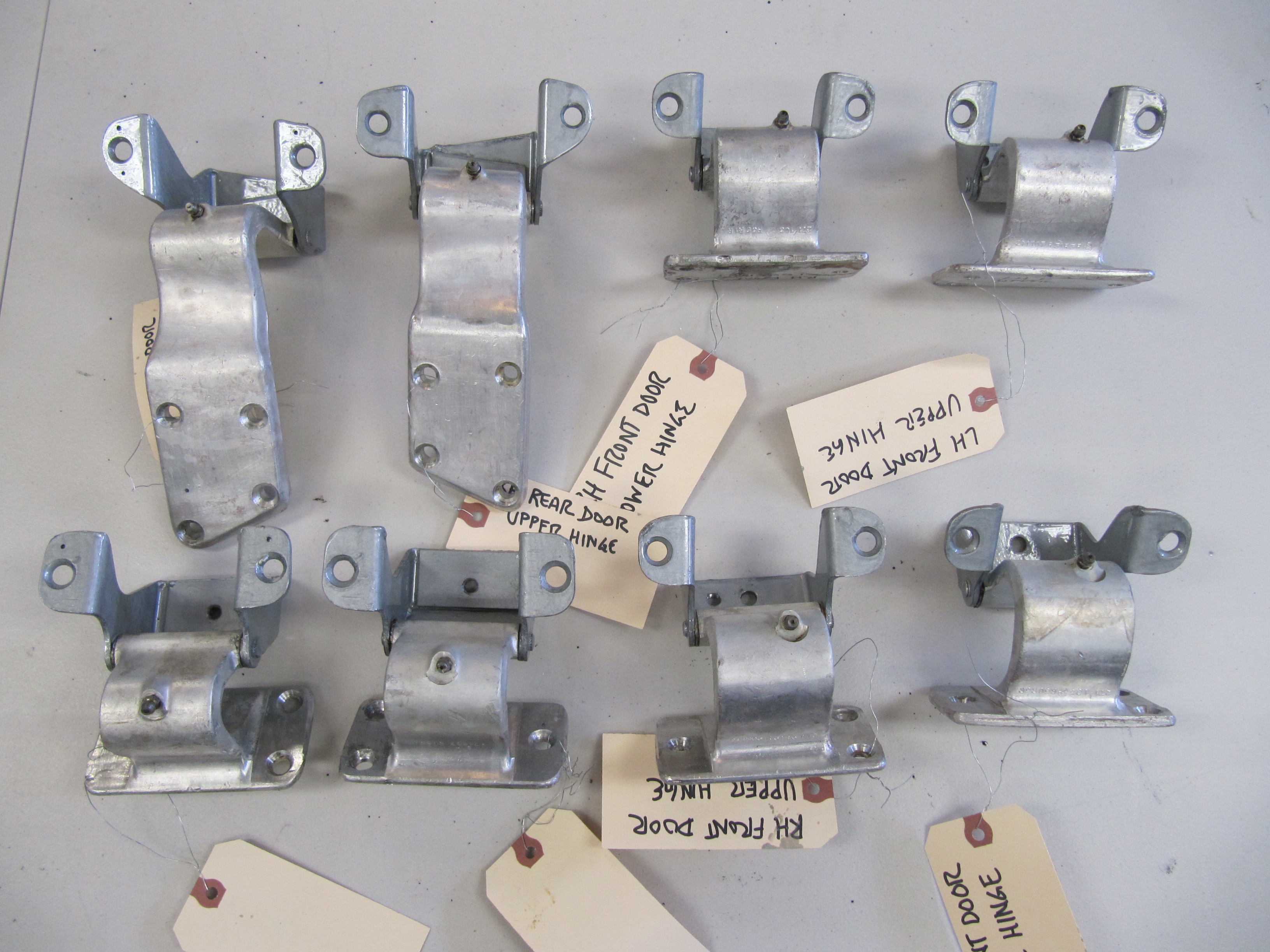
Cleaned Door Hinges

Painted with POR-15 Silver

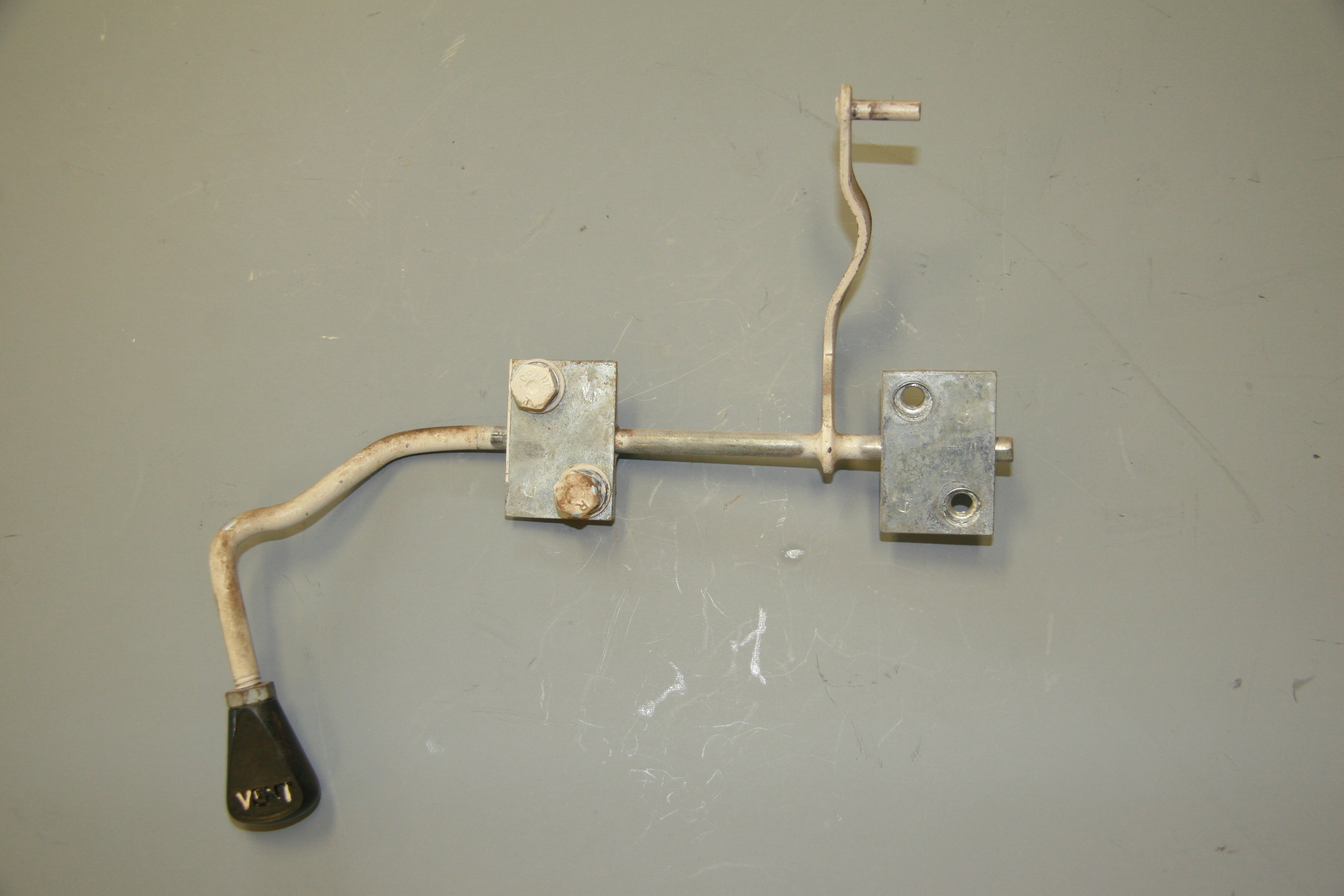
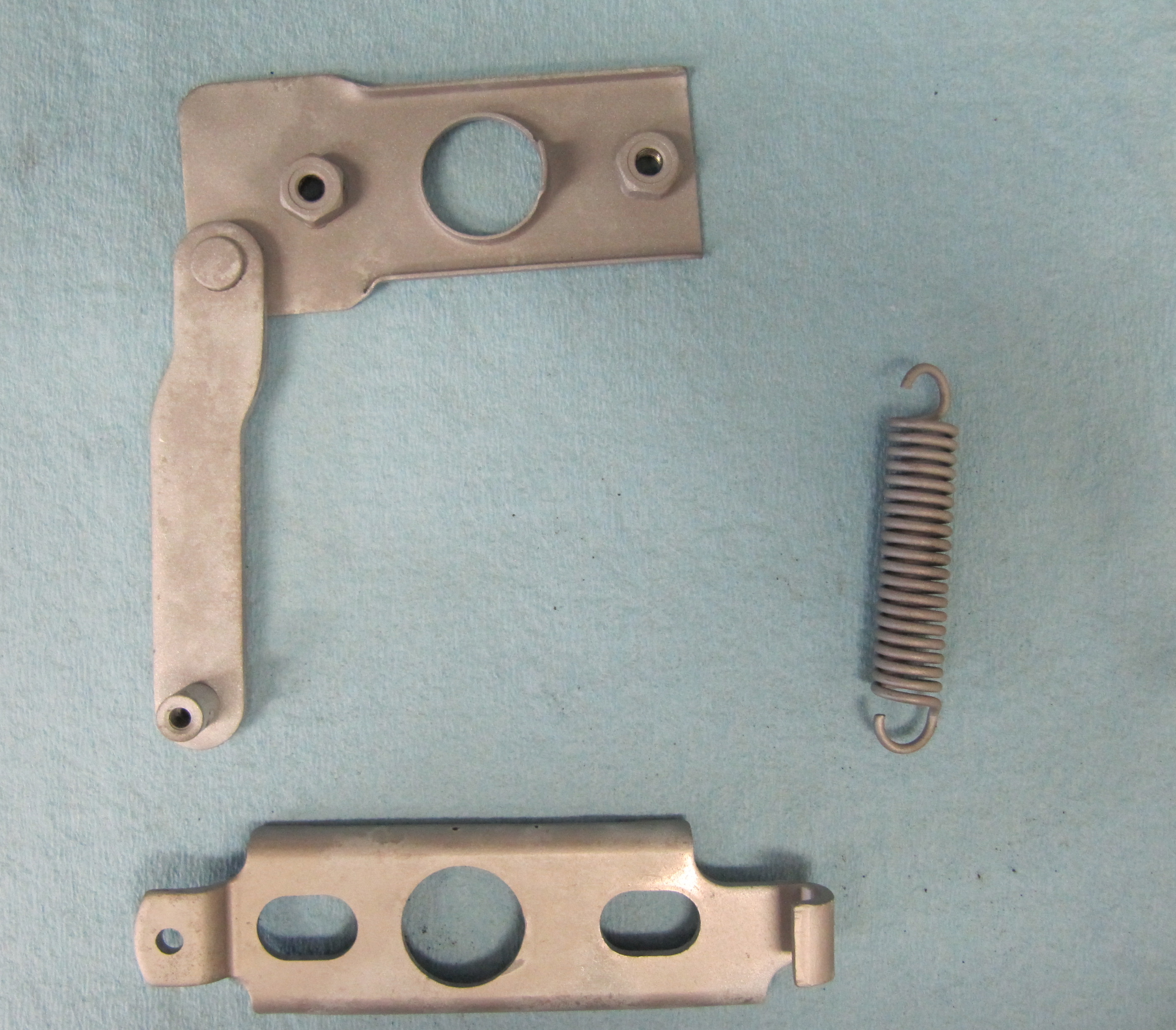
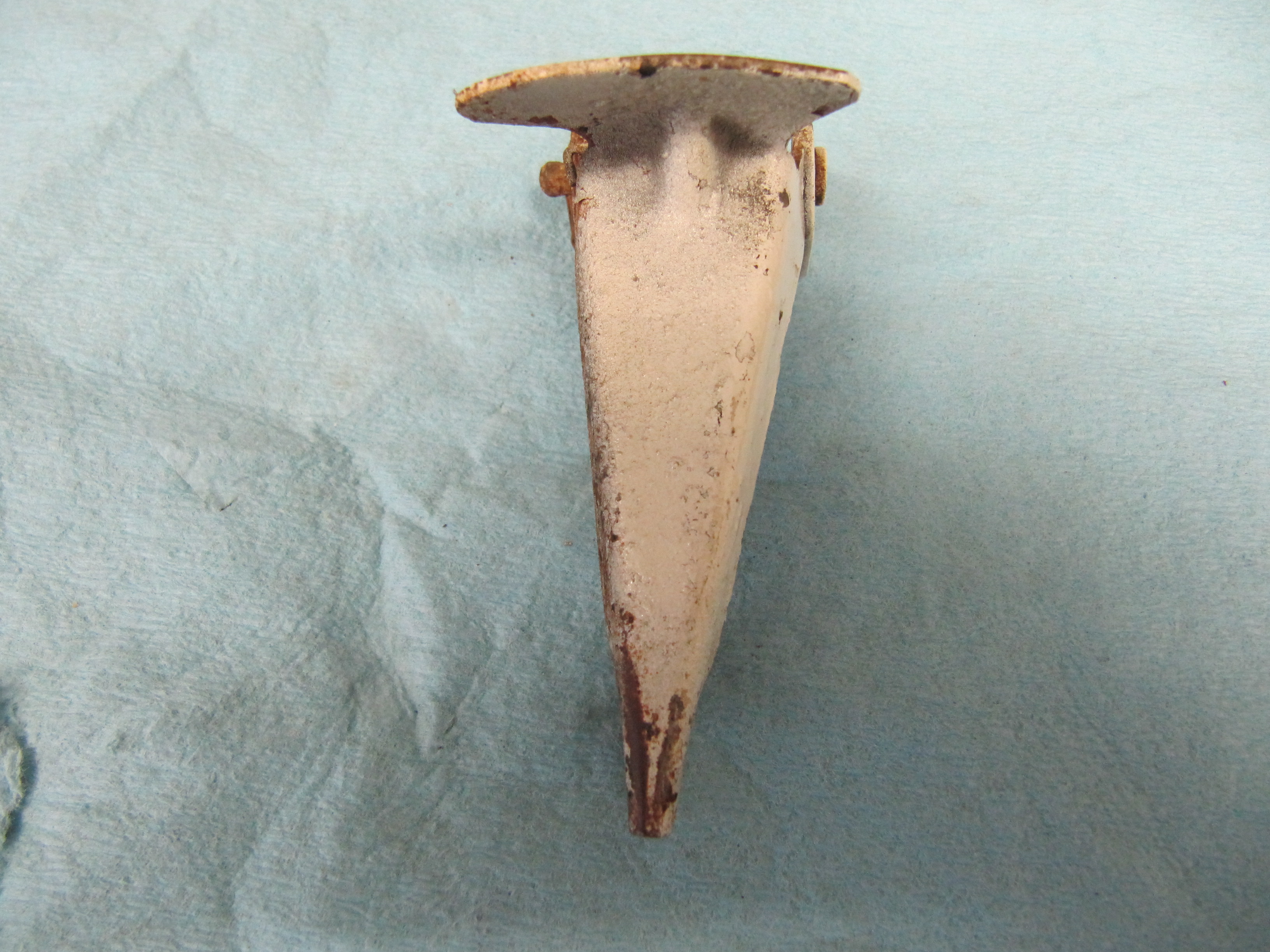
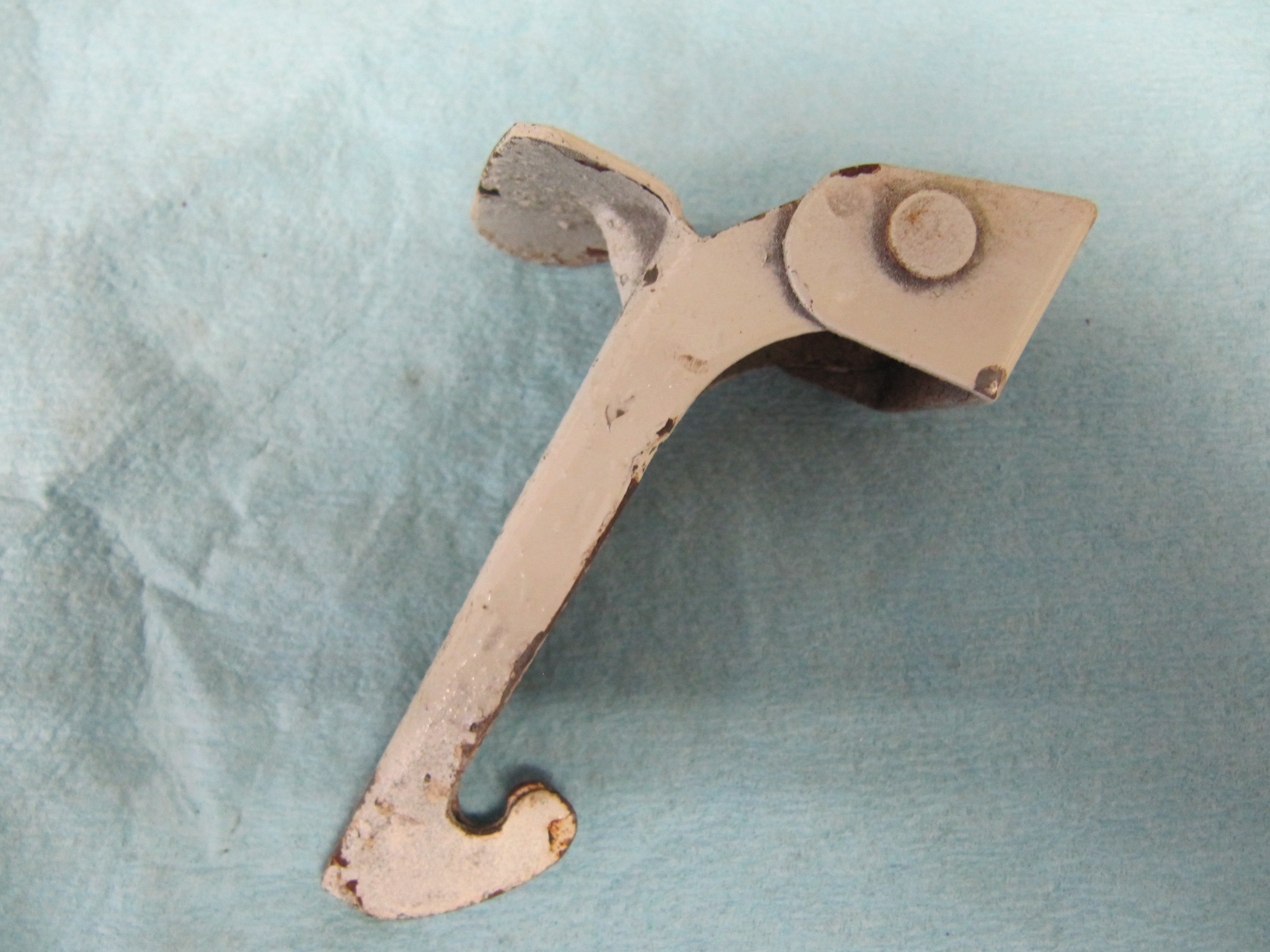
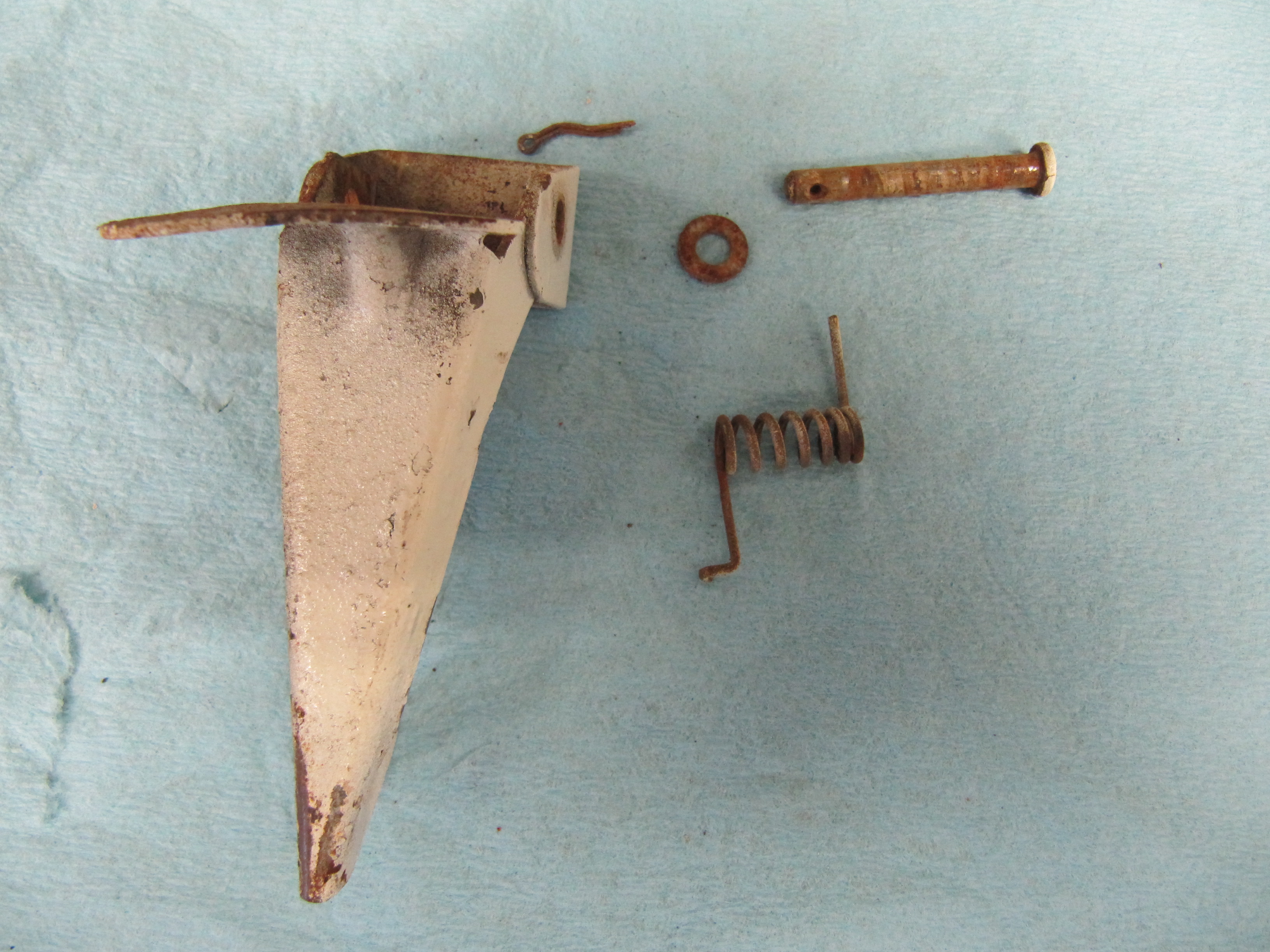
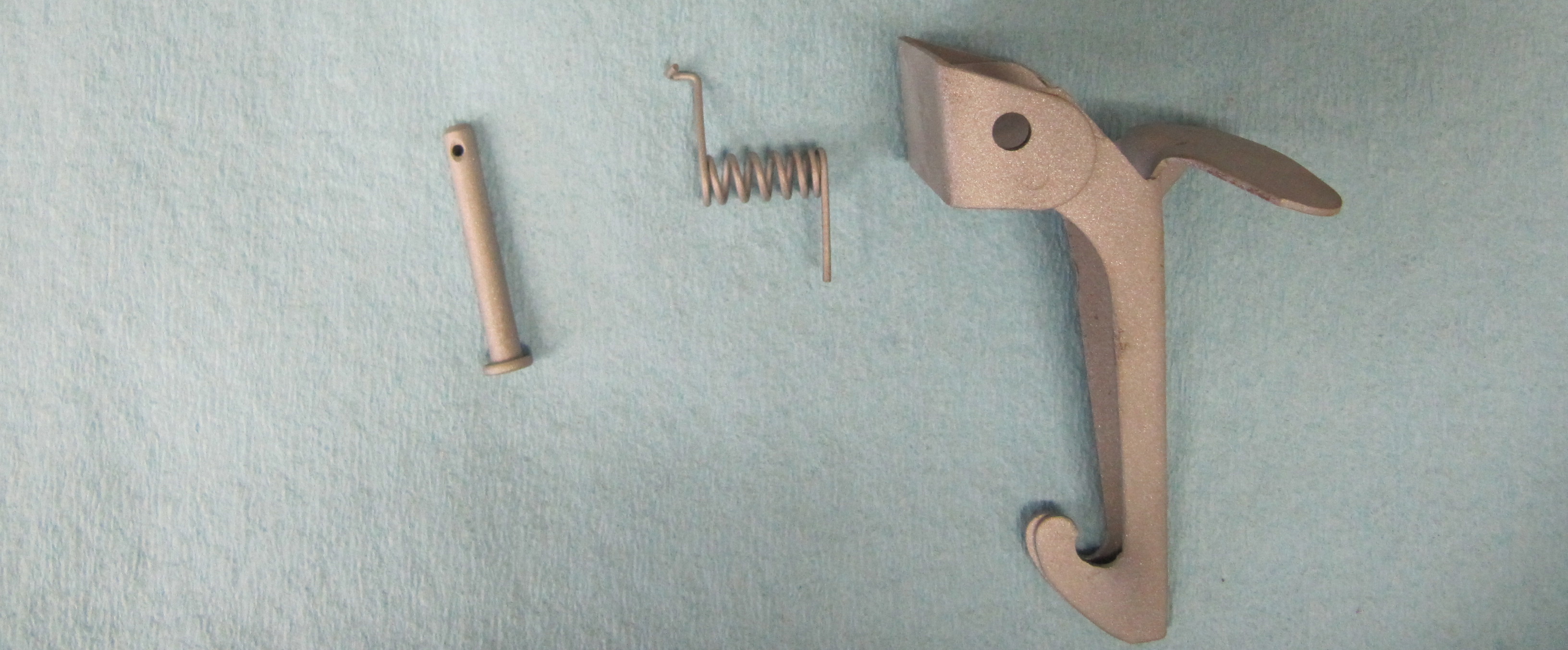
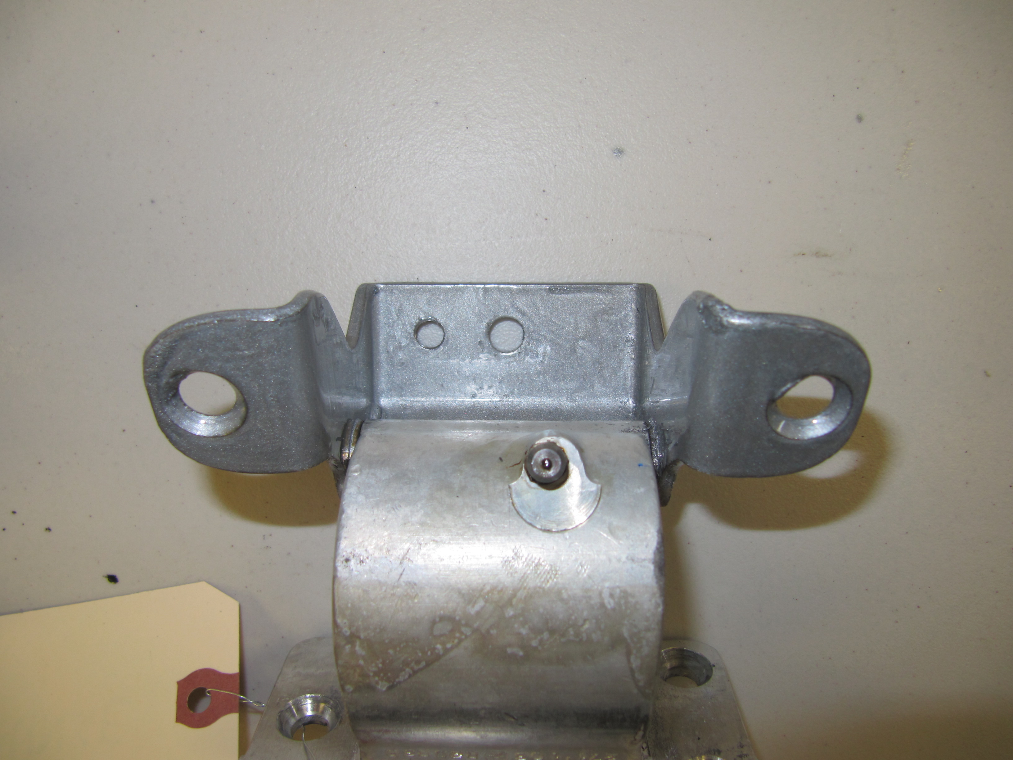
Door Check Arm Assemblies

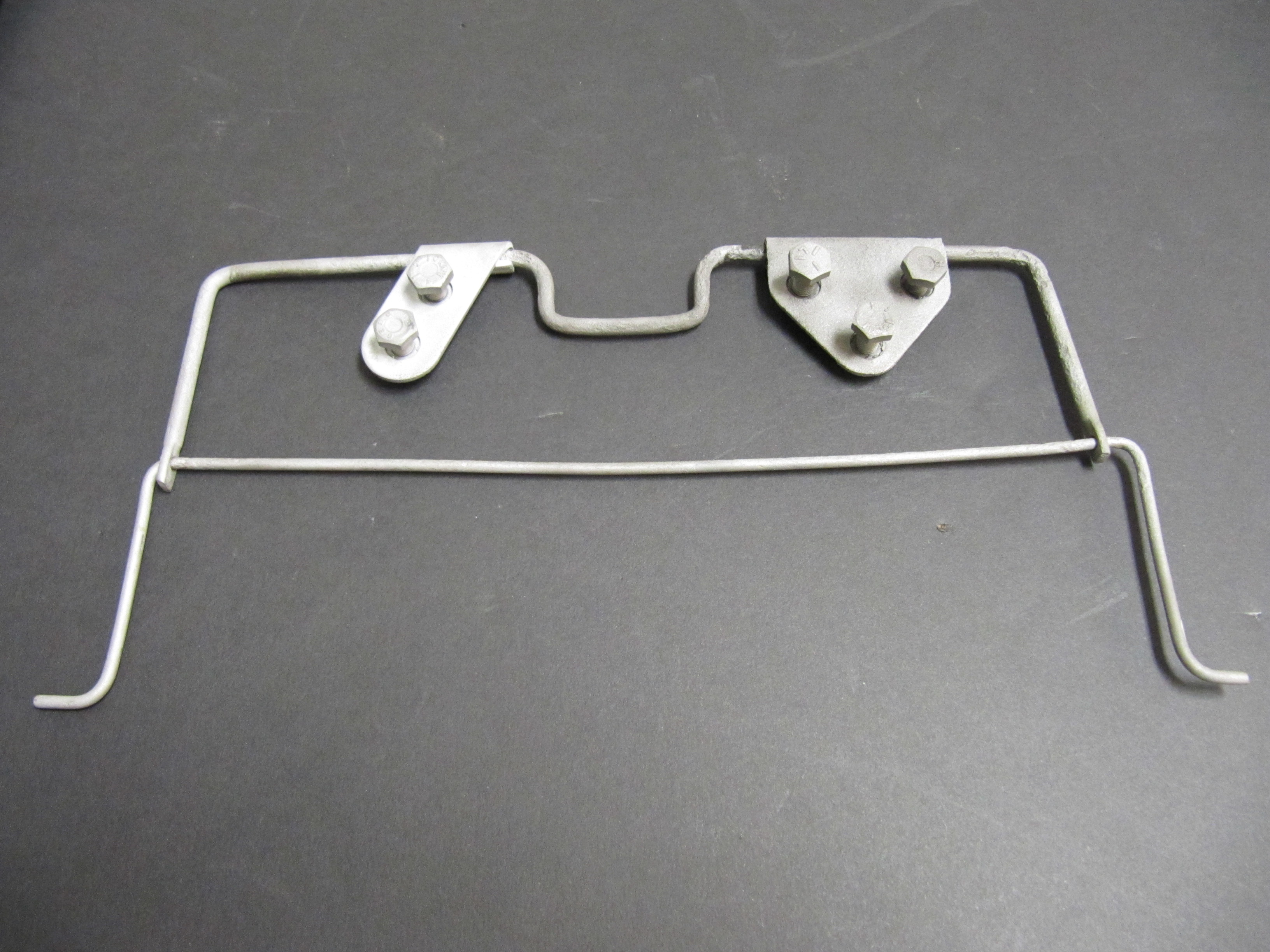
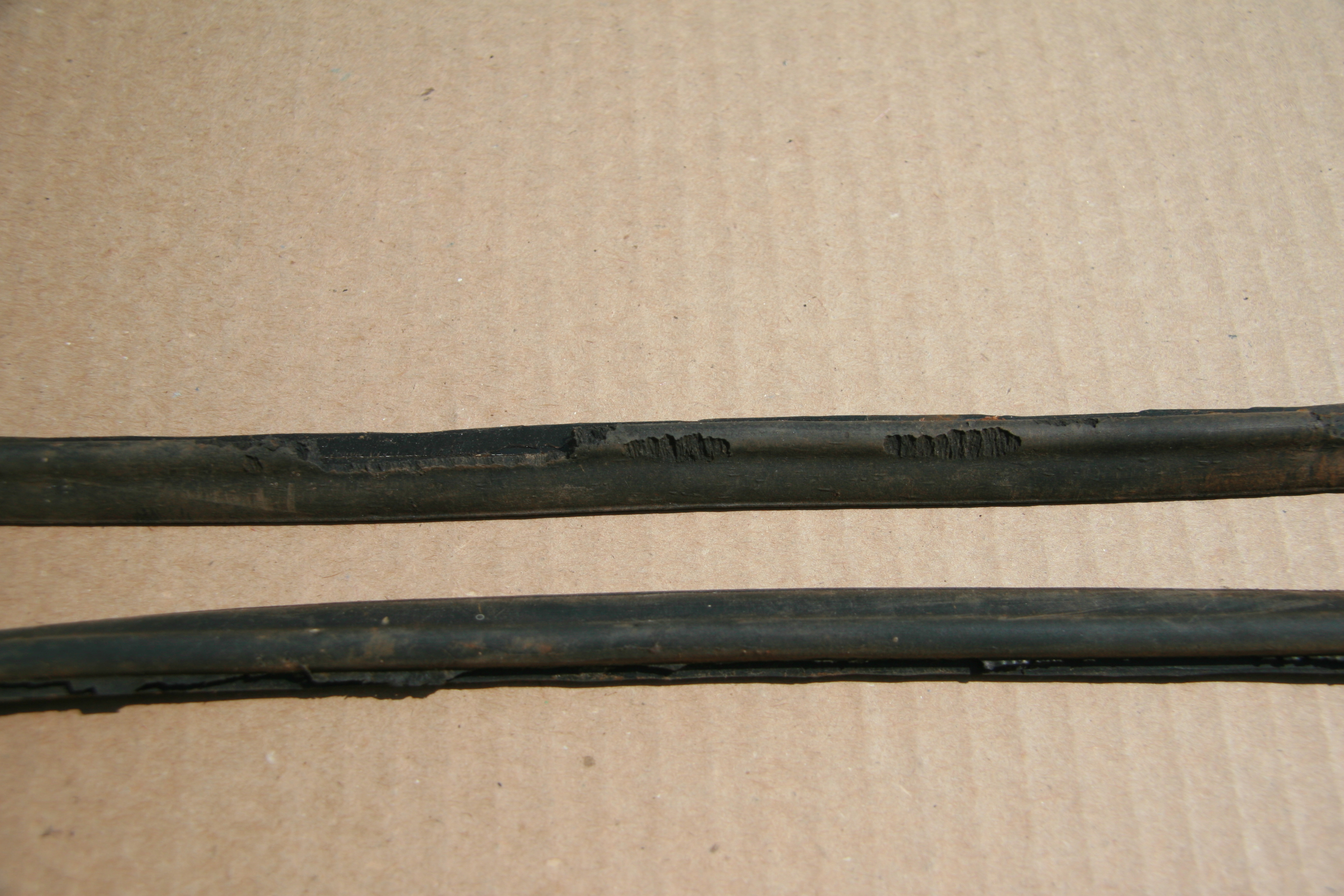
Each door has a check arm with a rubber buffer. The rubber buffer or stop is not available from the typical sources so I search for a suitable replacement material to use. I was unable to find anything that had the fabric rubber combination in the original stops. I media blasted each check arm and will have them zinc plated.

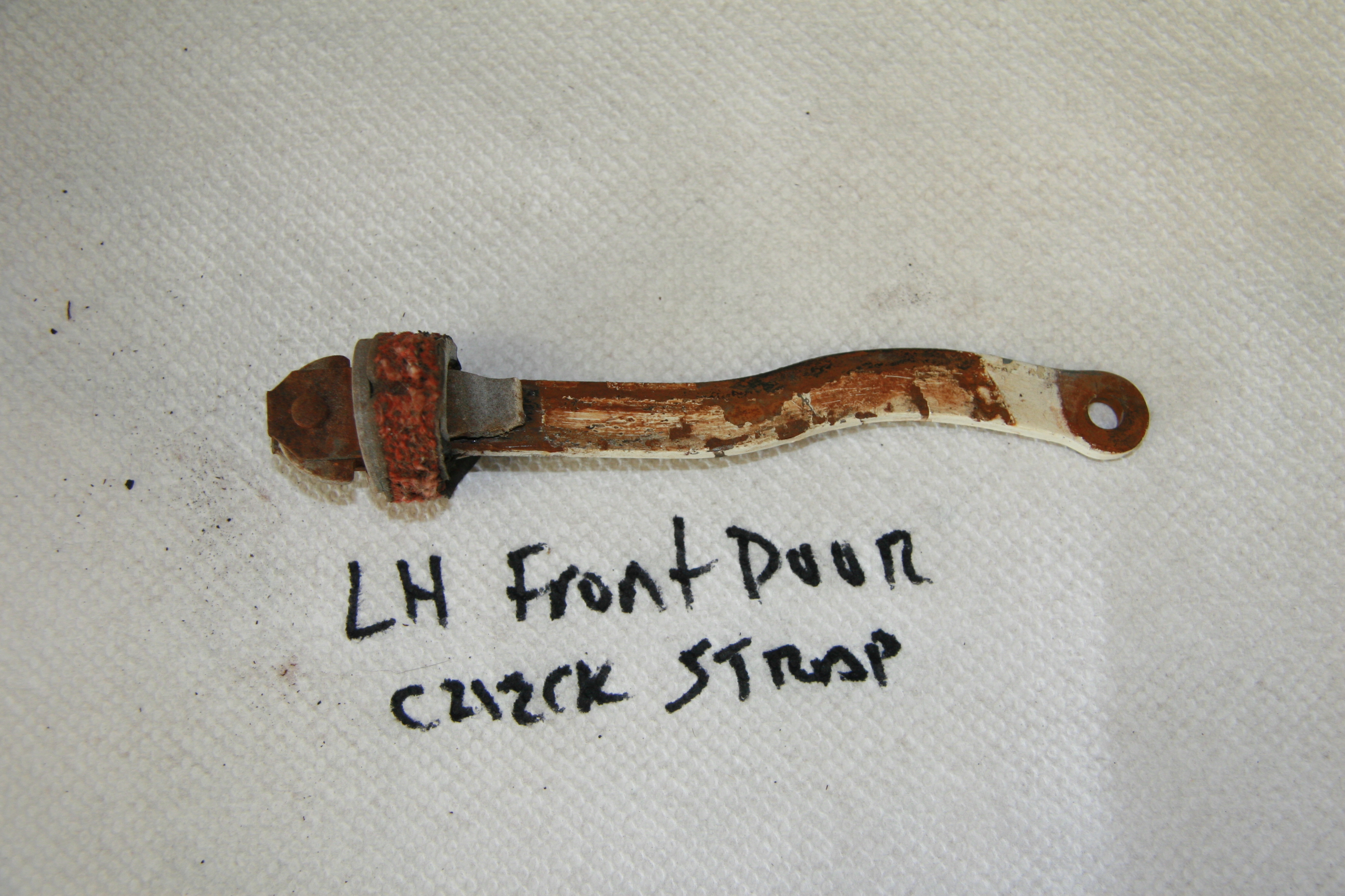
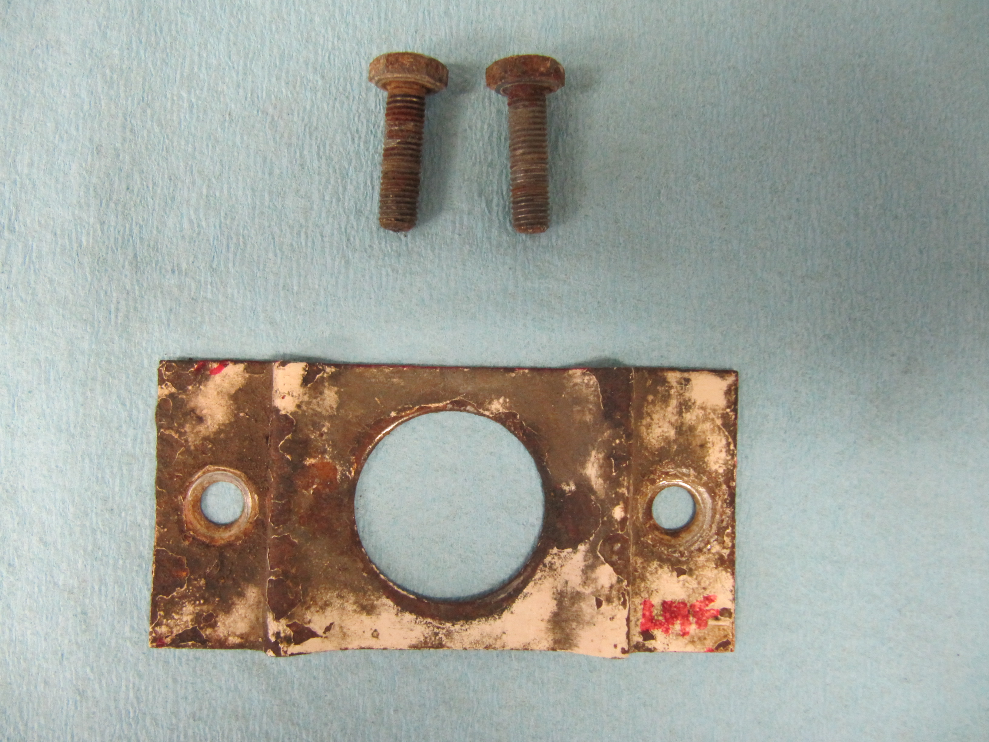
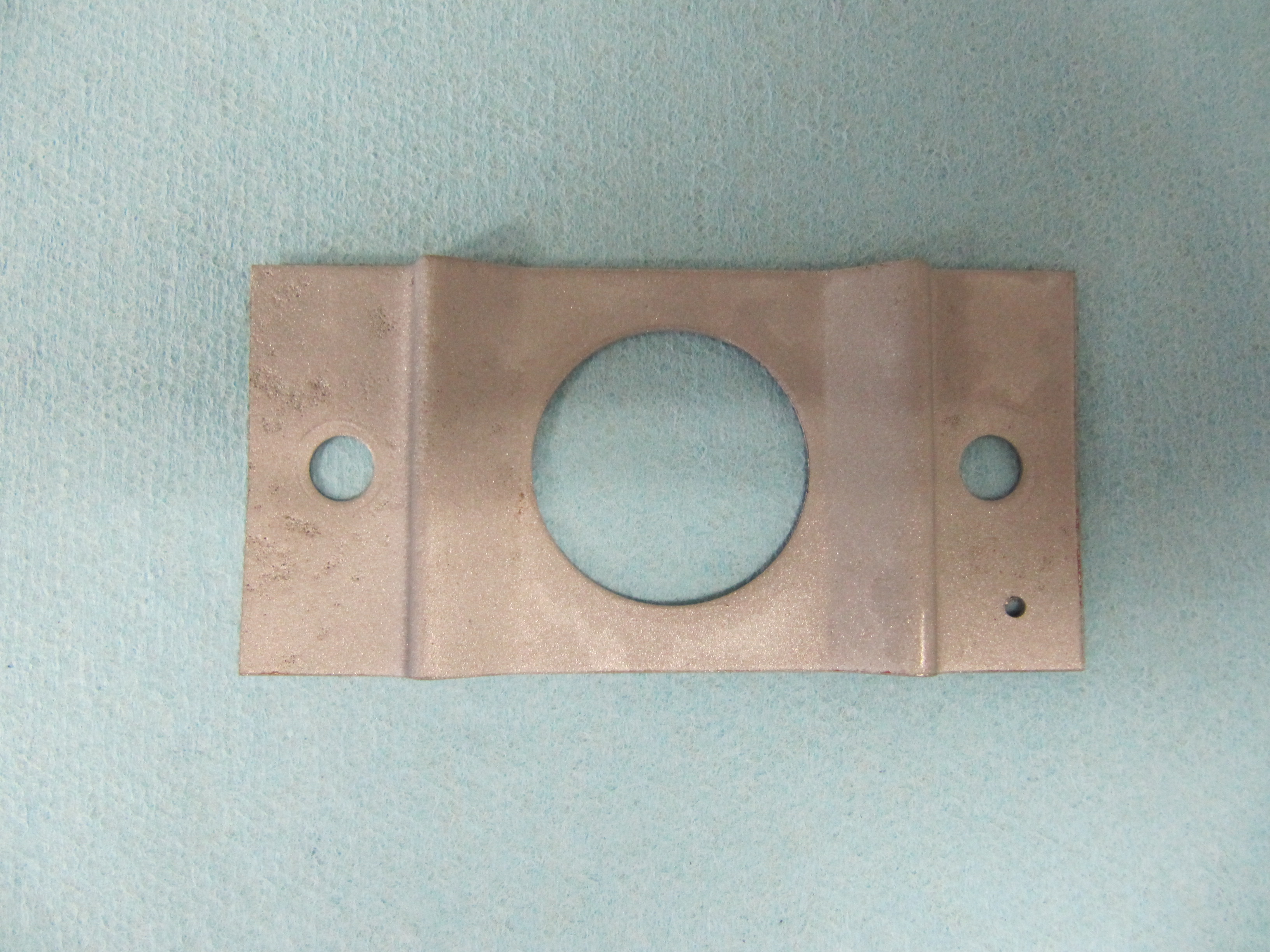
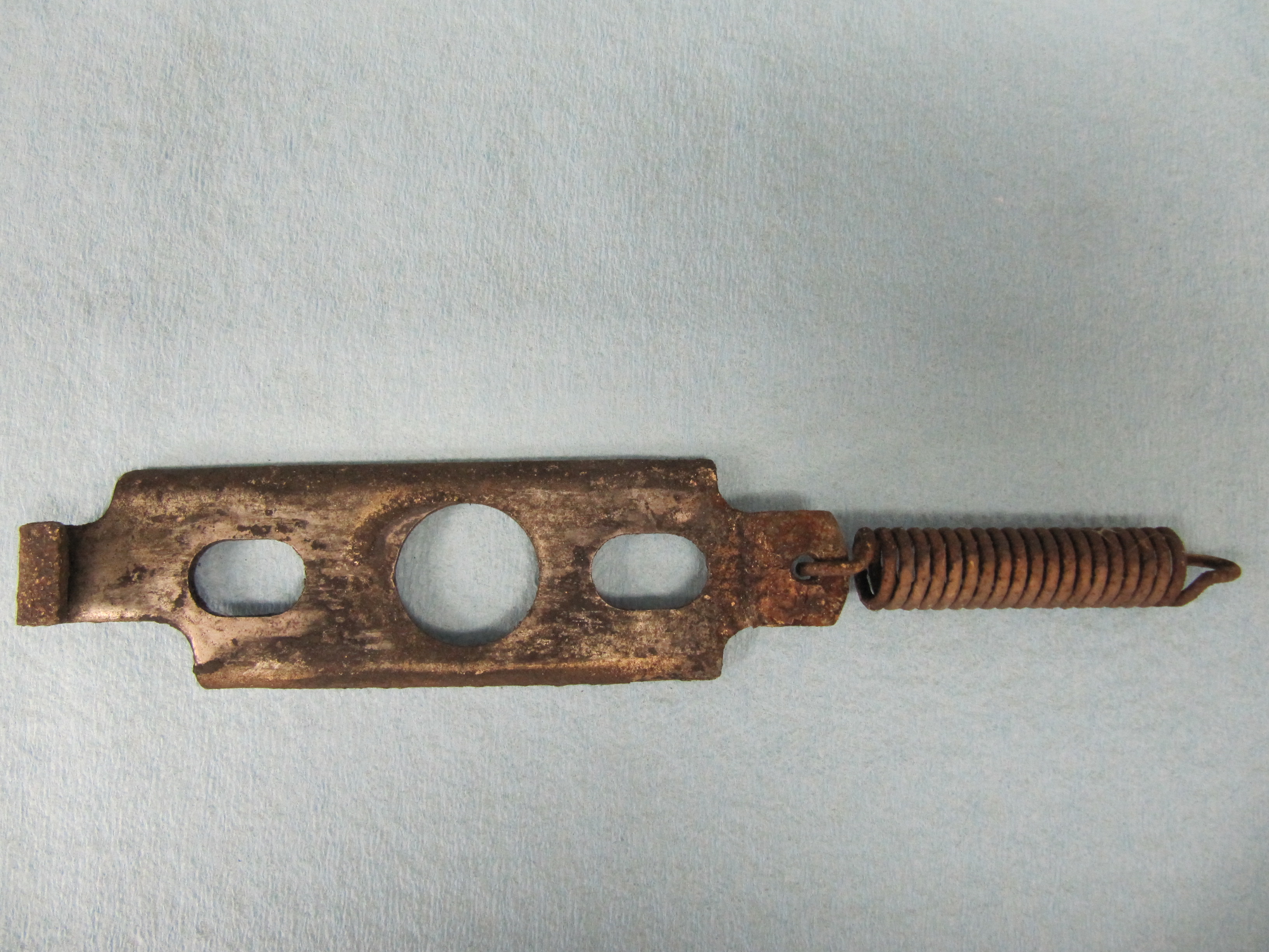
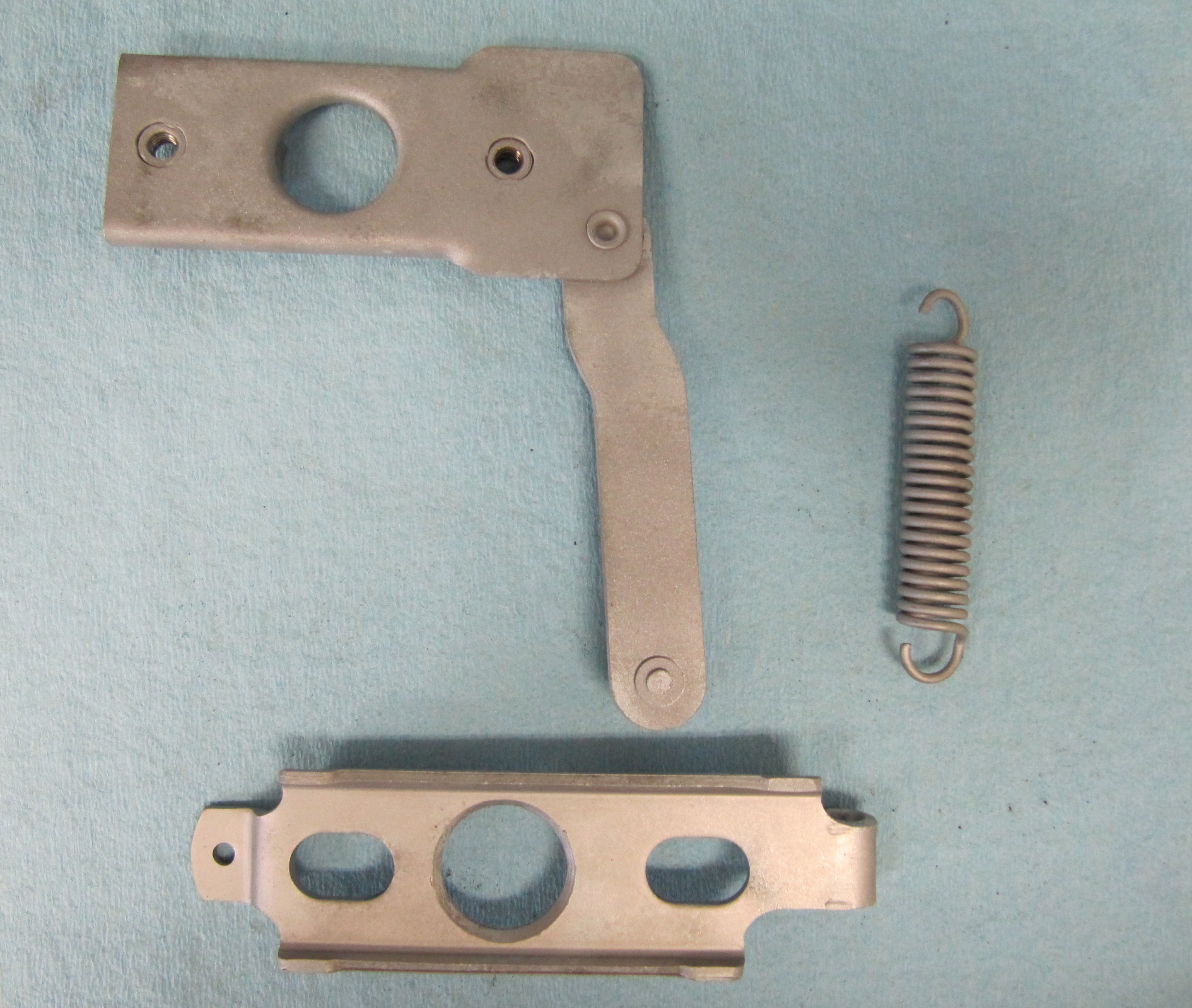
LH Front Door Check Arm Assembly

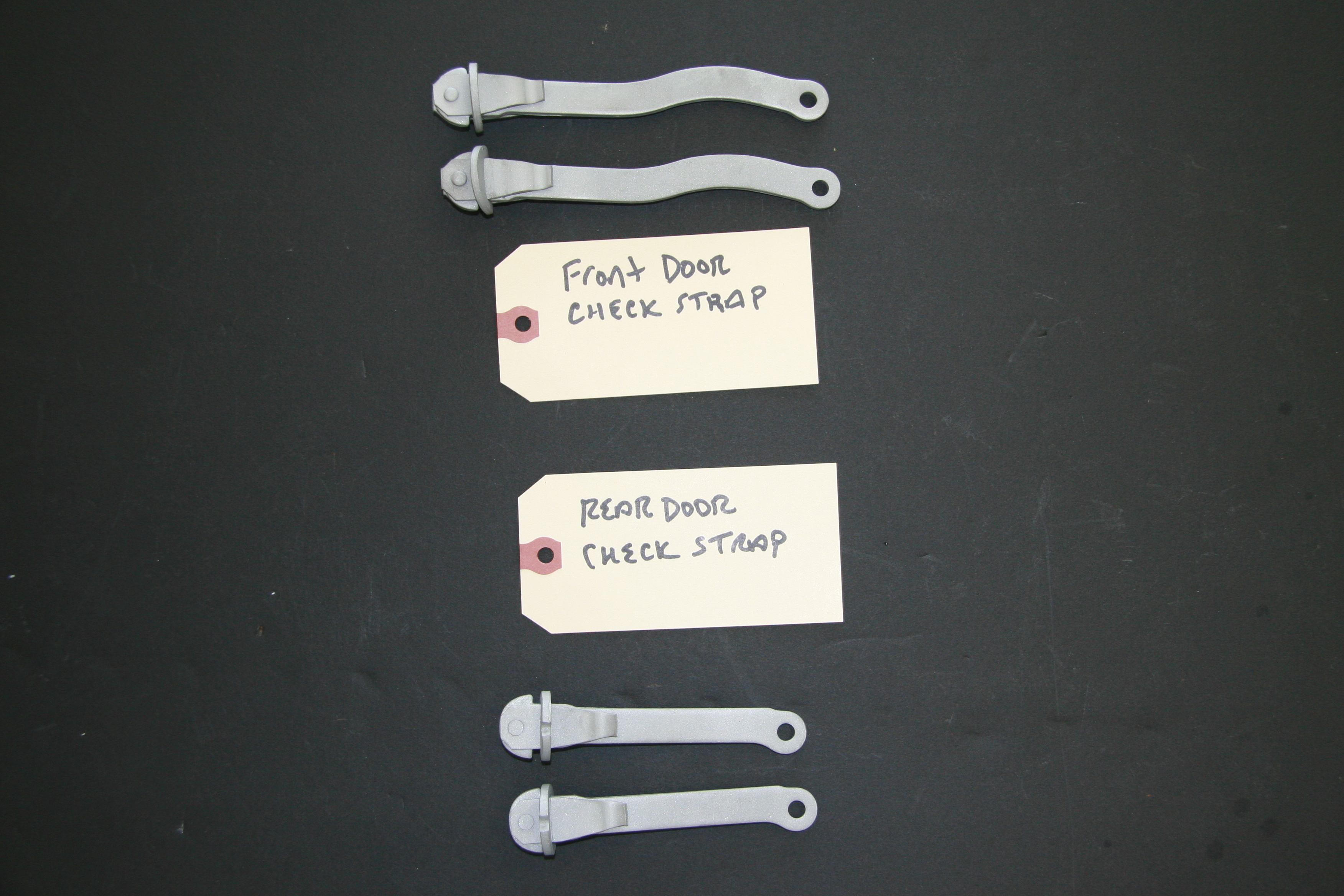
Front and Rear Check Arm Assemblies

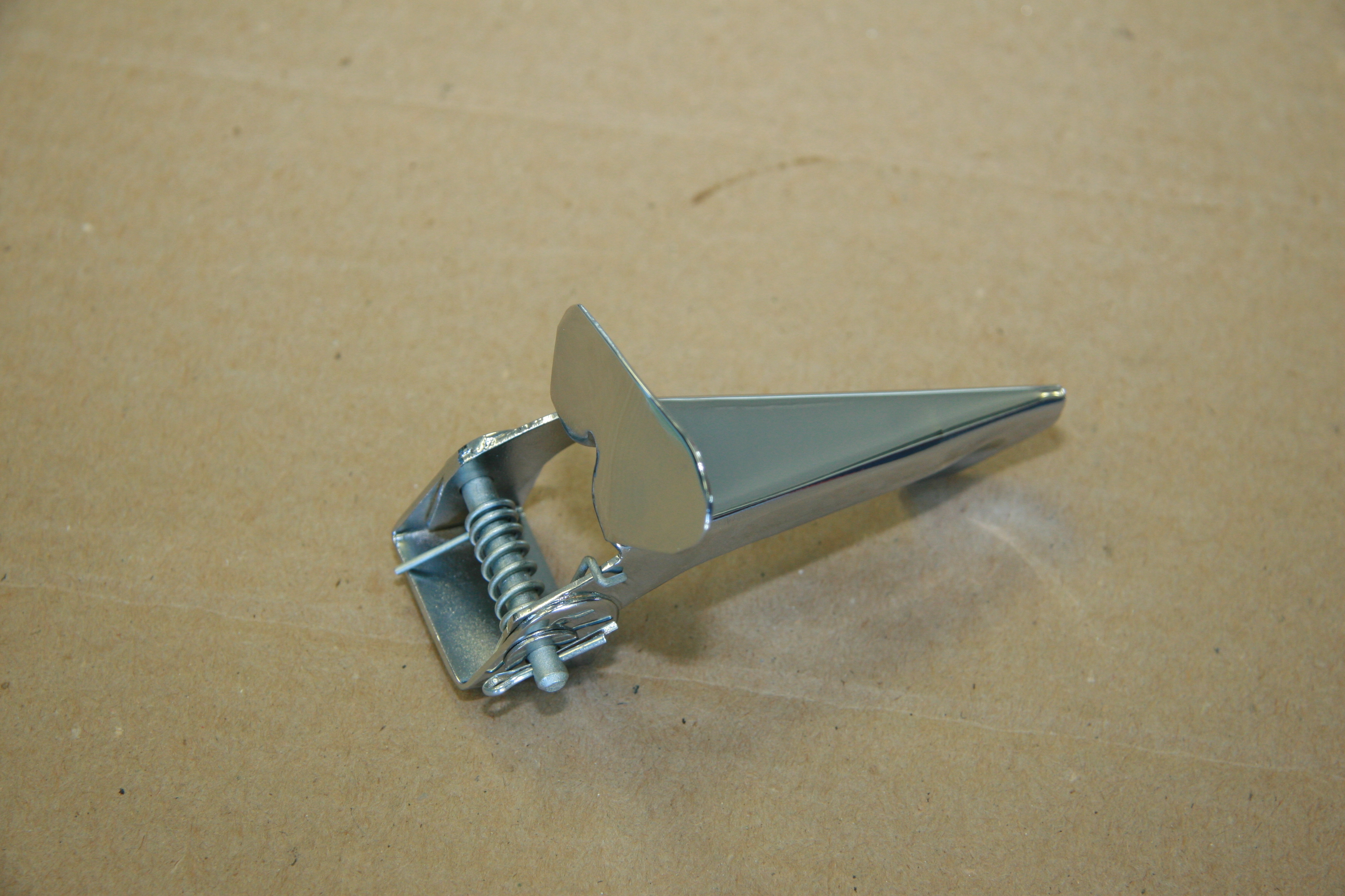
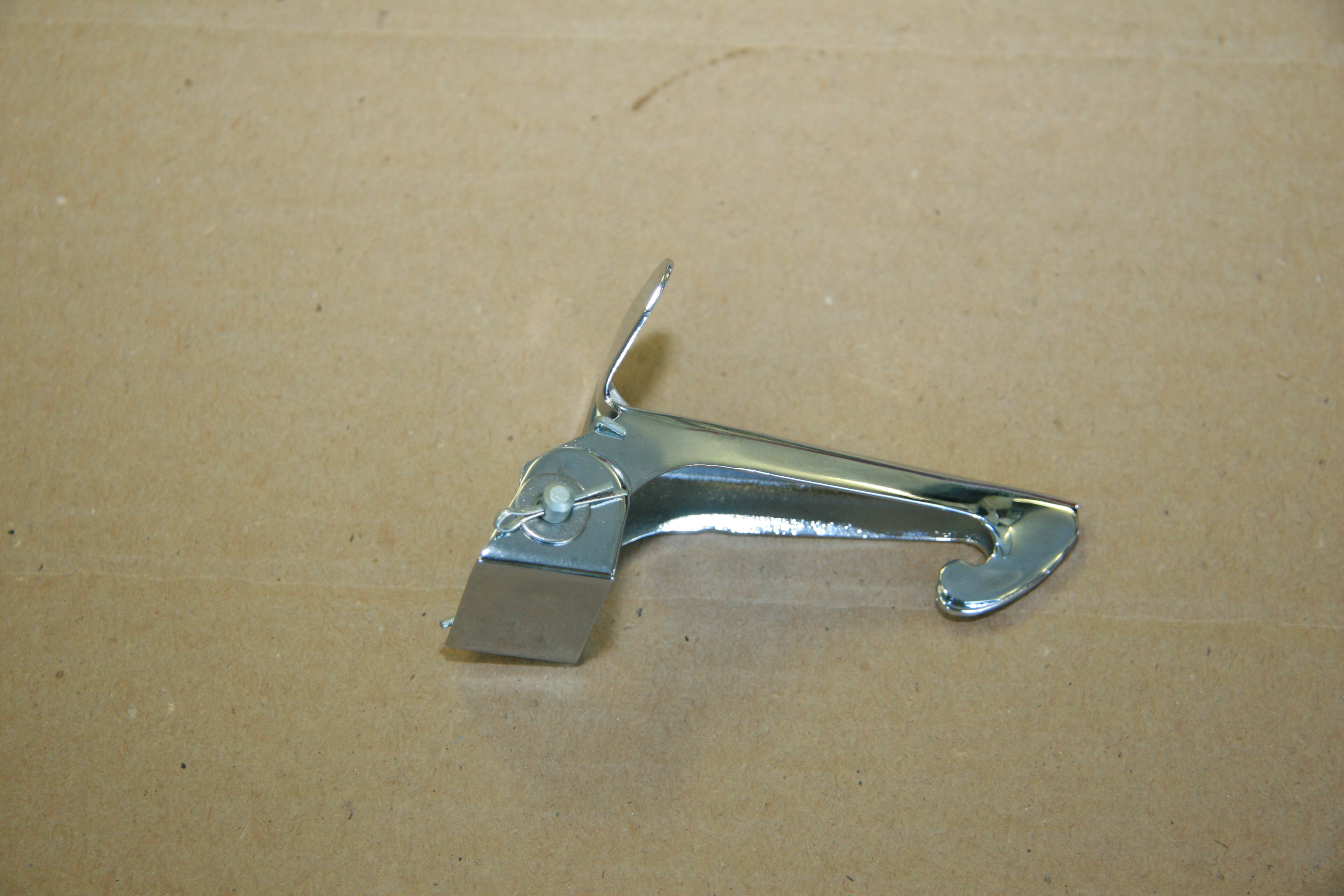
Rezinced Door Check Straps

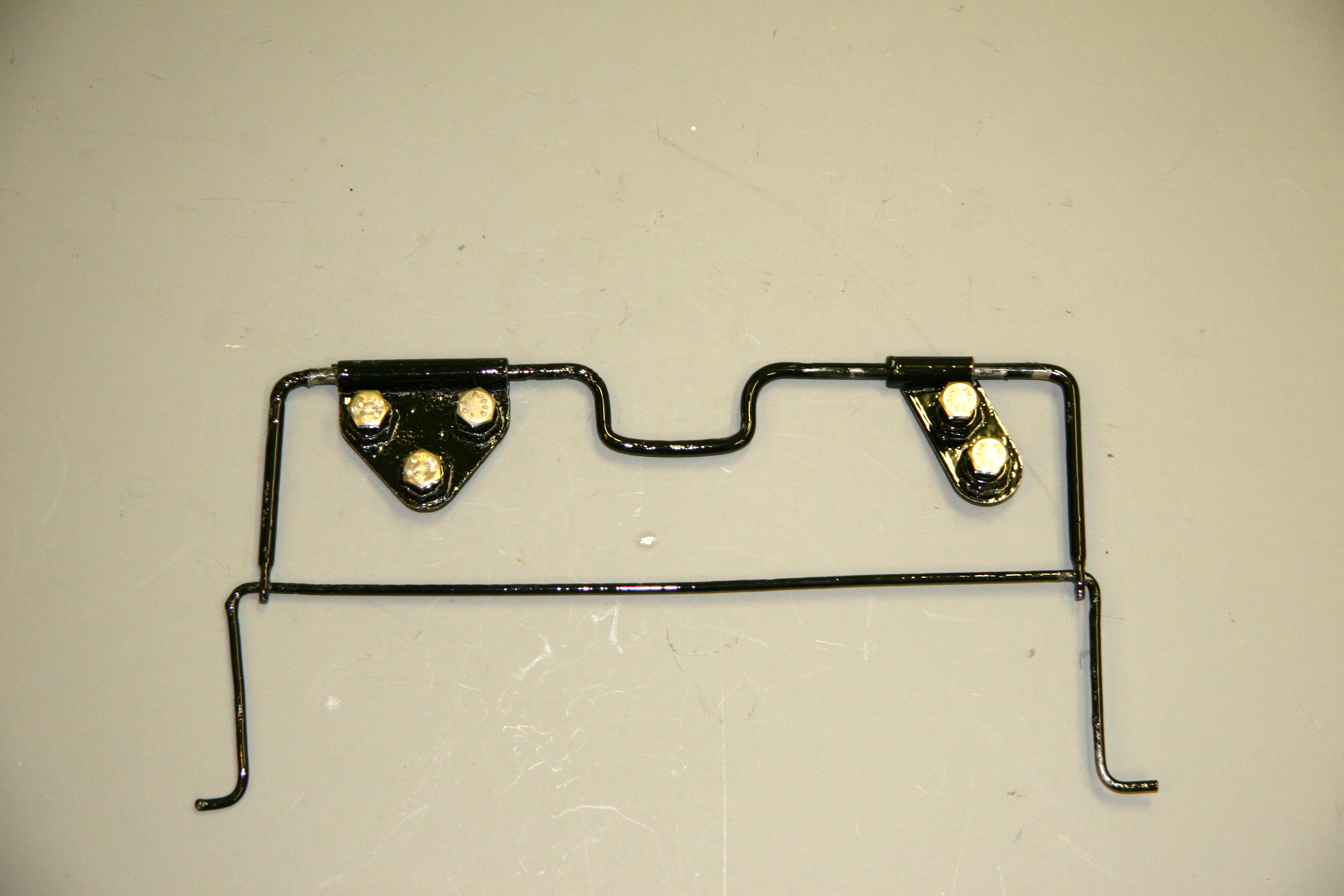
I ended up purchasing a 1/2″ thick Neoprene pad from Grainger and cut out the stops with a 1 1/8″ hole saw in my drill. Then using a 3/8″ and 5/8″ chisels I cut out the rectangular opening in each rubber stop. I will coat the circumference of the rubber with black silicone to provide some protection from moisture. I tried the stops on the check arms and installed one of the rear door check arms with the stop in a door. Everything seems to work well. Hopefully the new neoprene stops will hold up.

One and one eighth inch hole saw cut in half inch neoprene

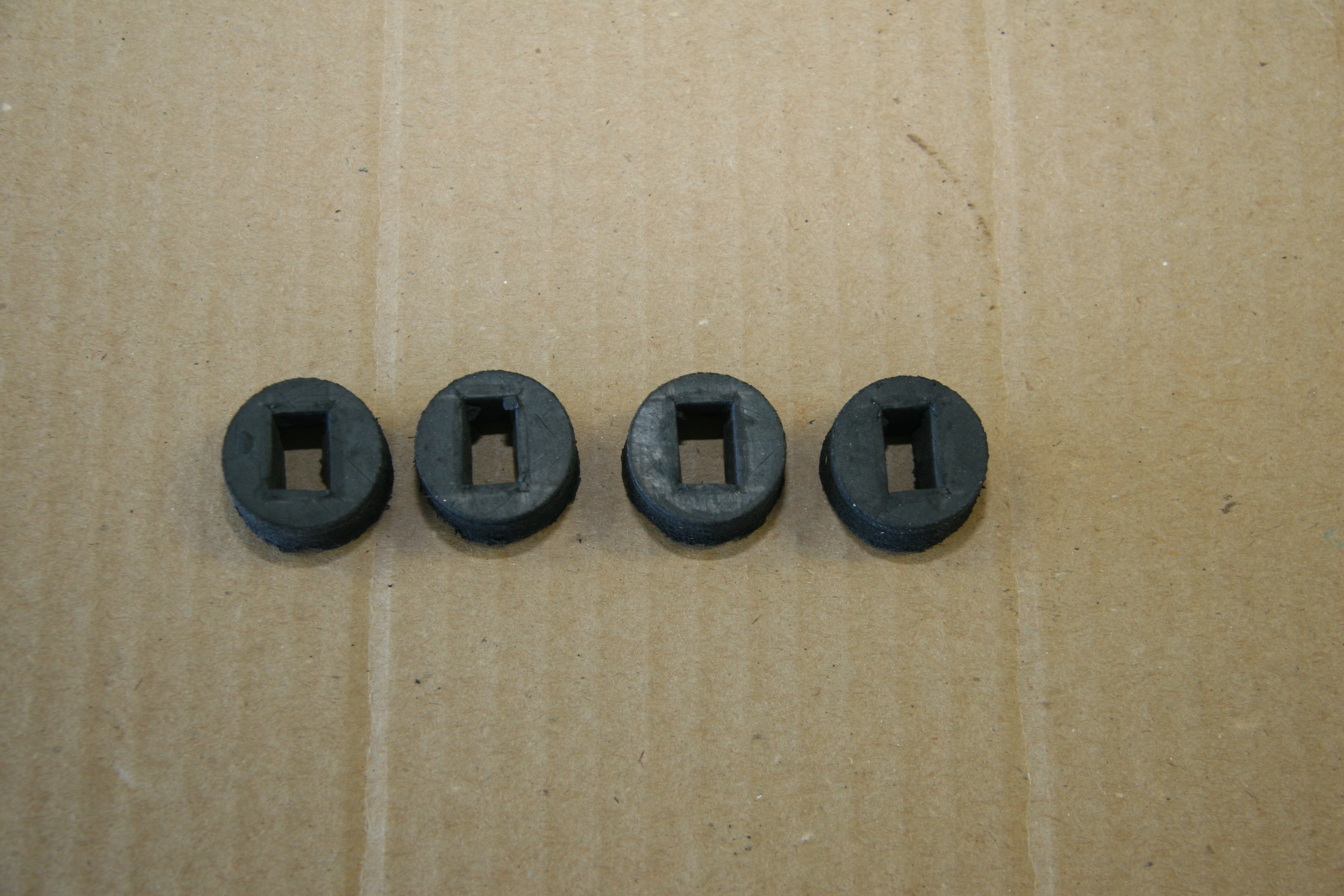
Neoprene Rubber stops for Door Check Arms

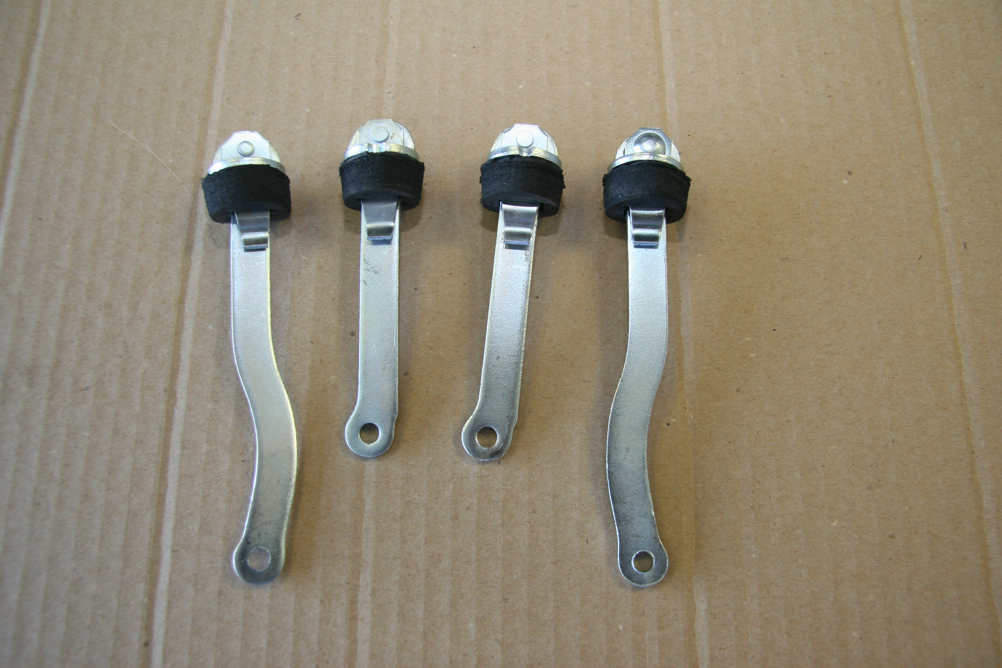
Front and Rear Door Check Arms with Neoprene Rubber Stops

I am not yet at the point where I am ready to install door seals; however, I came across some photos and installation instructions on the Jag-Lovers web site that may prove helpful later. This is a link to the page:

http://www.jag-lovers.org/snaps/snap_view.php3?id=1354948688

Door Hinge Shims

The rear doors had hinge shims on the upper hinges. The LH with two shims and the RH with three. I media blasted the hinges and will then zinc plate them. All of the shims were the same thickness.

LH Rear Upper Shims

RH Rear Upper Shims

Installing the Mk2 Doors

I knew from other car restorations that door mounting is never fun, nor easy. I decided that I would practice mounting the MK2 doors a couple of times before doing the real thing after fresh paint had been applied!

First, I installed the exterior door handles on each door, because these become impossible or nearly impossible to access once the windows and there frames go into place. Additionally, this gives the person holding the door for mounting something comfortable and convenient to grasp while holding the door. Each handle has two #10-32 mounting studs with a flat washer, shakeproof washer and nut. The front of the handles had what appeared to be leather or fiber pads between the handle and the door when I removed them from the car. I replaced these with neoprene pads that I cut to shape. Once finally mounted, these can be cut to shape with a sharp razor knife.

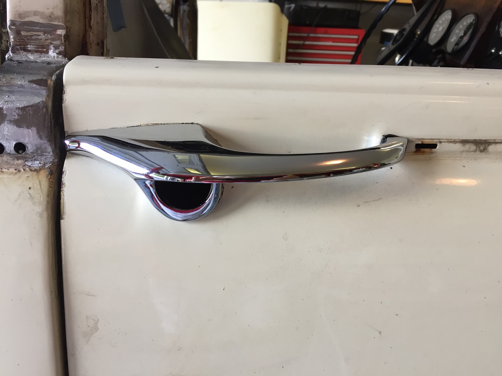
Exterior Door handle with Neoprene Cushion

After wrestling with the door installation quite a bit, I finally concluded that the best approach is to first, bolt the hinges to the doors with the bolts barely started in the captured threaded plates. Then lift the doors to the car ( a second person, or a special purpose jack designed for the job, is particularly helpful here!) and then start the pozi-drive screws through the hinges into the “A” pillar or “B/C” pillar. Again, everything its barely started, nothing tightened. After all of the pozi-drive screws are mounted, it is then time to install the 5/16-24 x 1 hex head bolts through the center of the hinges into the pillars. The front door hinges also have the two 5/16-24 interior lights switches that need to be started and these are located in the center of the lower hinges.
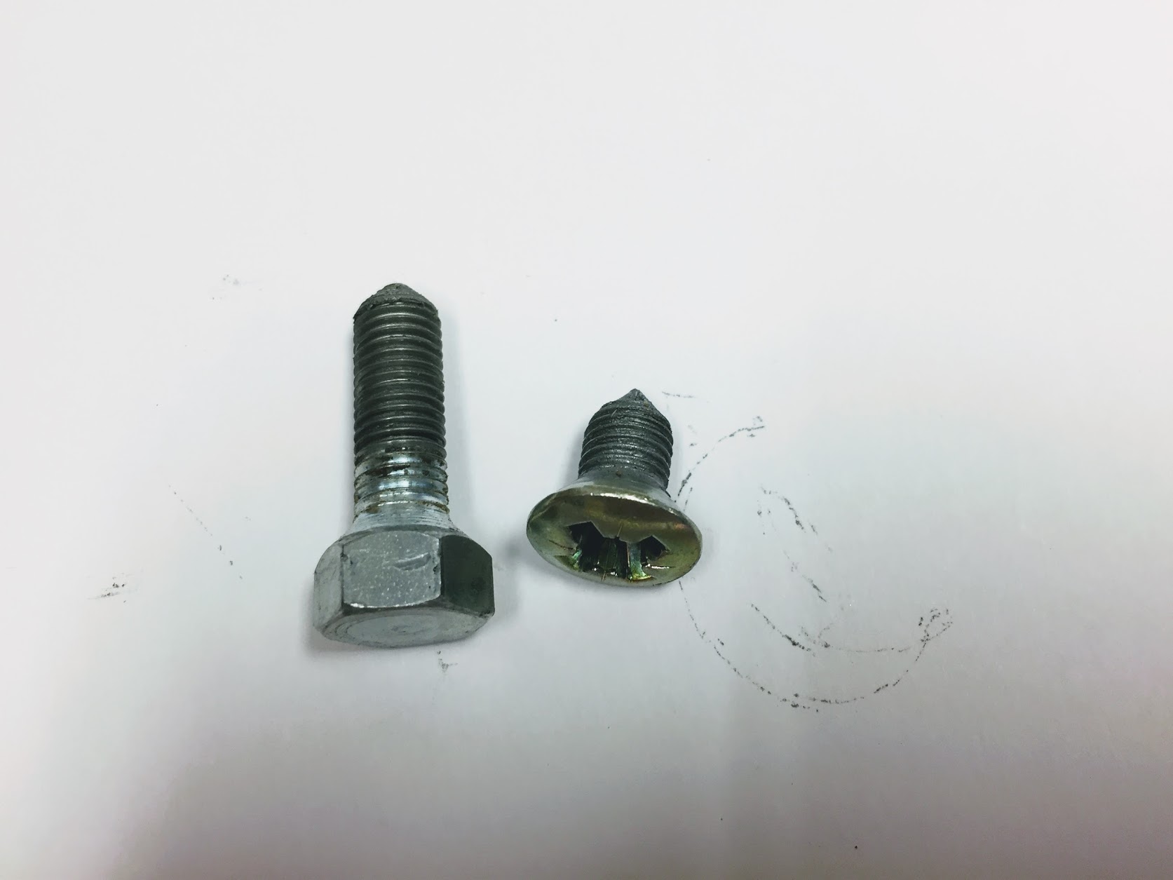
Door Fasteners

After all of the fasteners are started, it is then a matter of tightening the screws and bolts until they start to “hold” the door, but with adjustment (movement) still possible. Door gaps can then be manually sorted until you end up with what you want. This is a slow process requiring patience. I did all of this without the lock strikers installed. To simulate where the rear shut lines should be I rolled up some tape and then taped it to the door jam to buffer the closing of the door – the job that the seals will ultimately do.

Once the doors are where you want them, the door strikers can be installed. On my car, each of the door strikers had a shim. The strikers have quite a bit of adjustment and like the doors require a fair amount of “fiddling” until you end up with a door closure that you are happy with. More information about the door handles and locks can be found in this post: https://valvechatter.com/?p=6027

Window Regulator Installation

The front and rear regulators are different designs but the same procedures for installation apply. I found it easiest to compress (by turning the winding crank) the mechanism to its smallest size. Insert the mechanism into the door and then crank the winder the other direction to spread the regulator and align it with its mounting holes in the door. One can then loosely start the mounting screws to support the mechanism in the door. This process is best demonstrated in a video. The is the installation in a rear door of the Jag.

It is a fairly easy process once you get the hang of it.

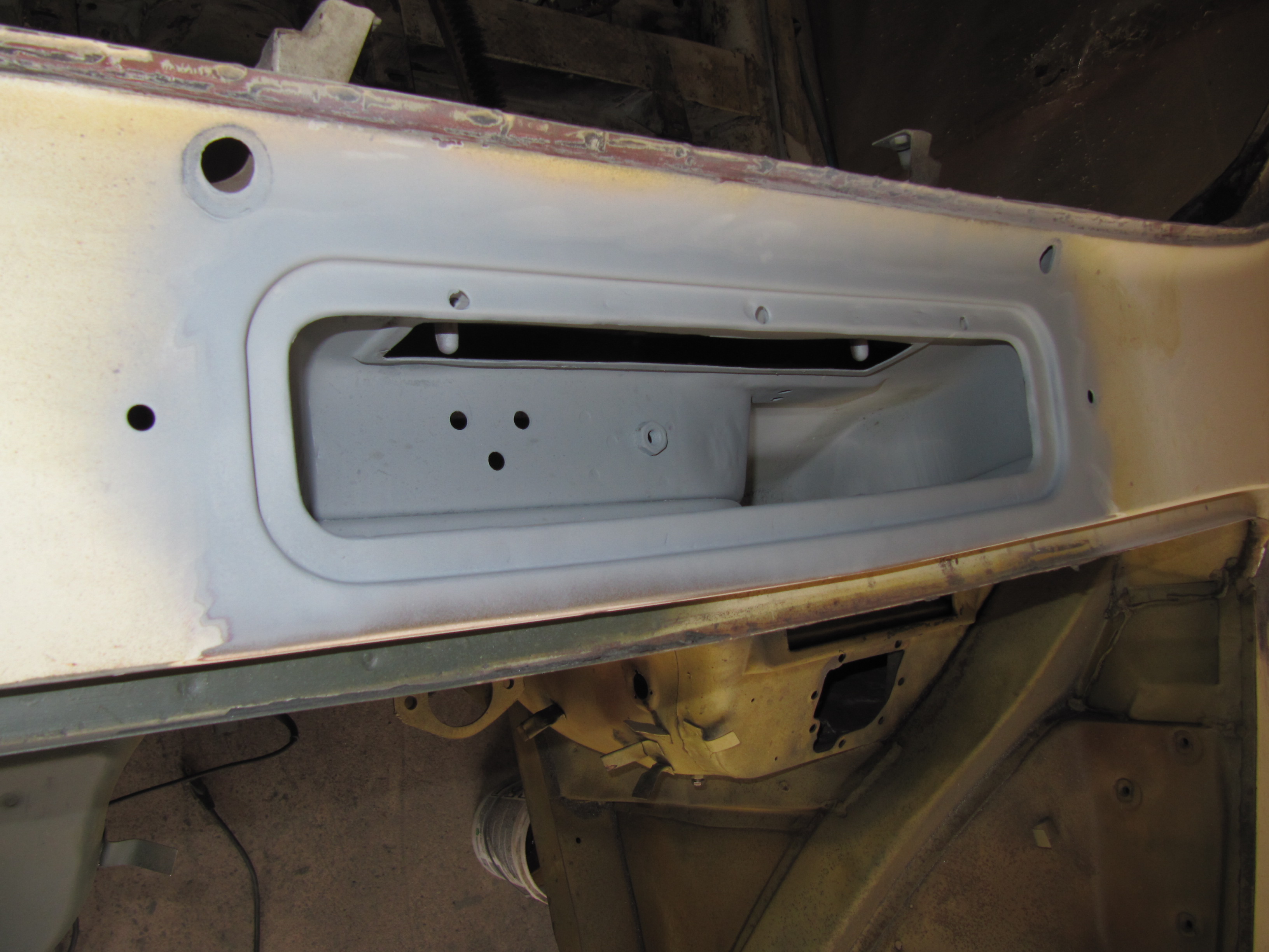
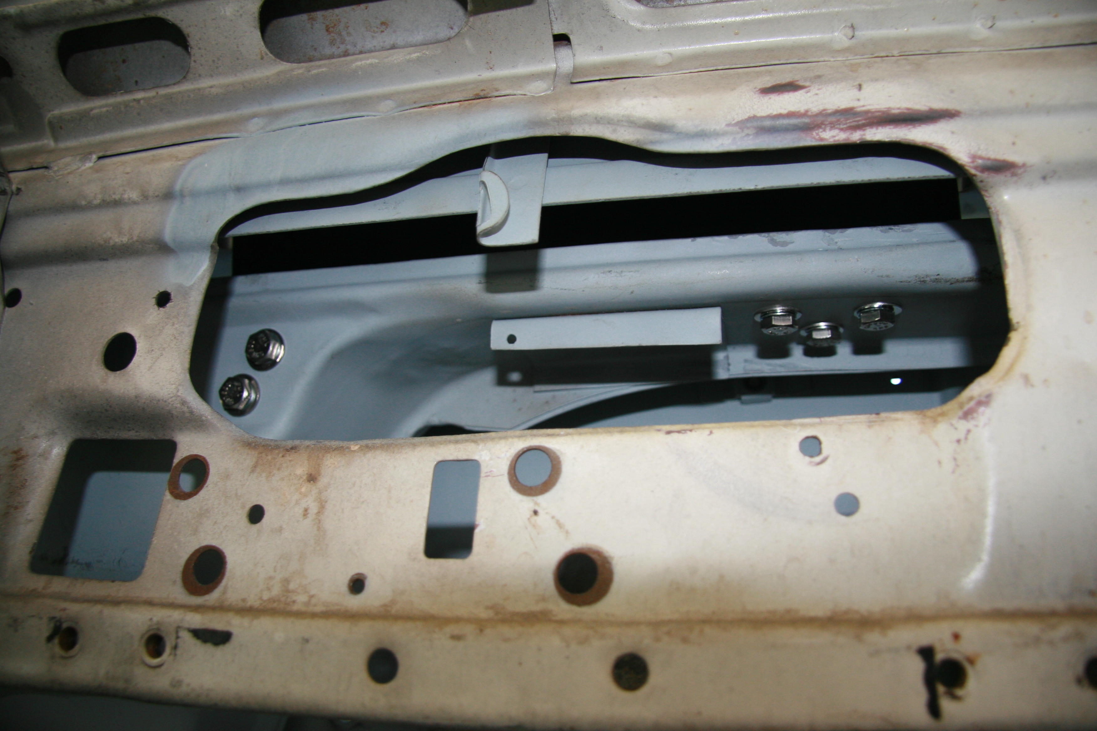
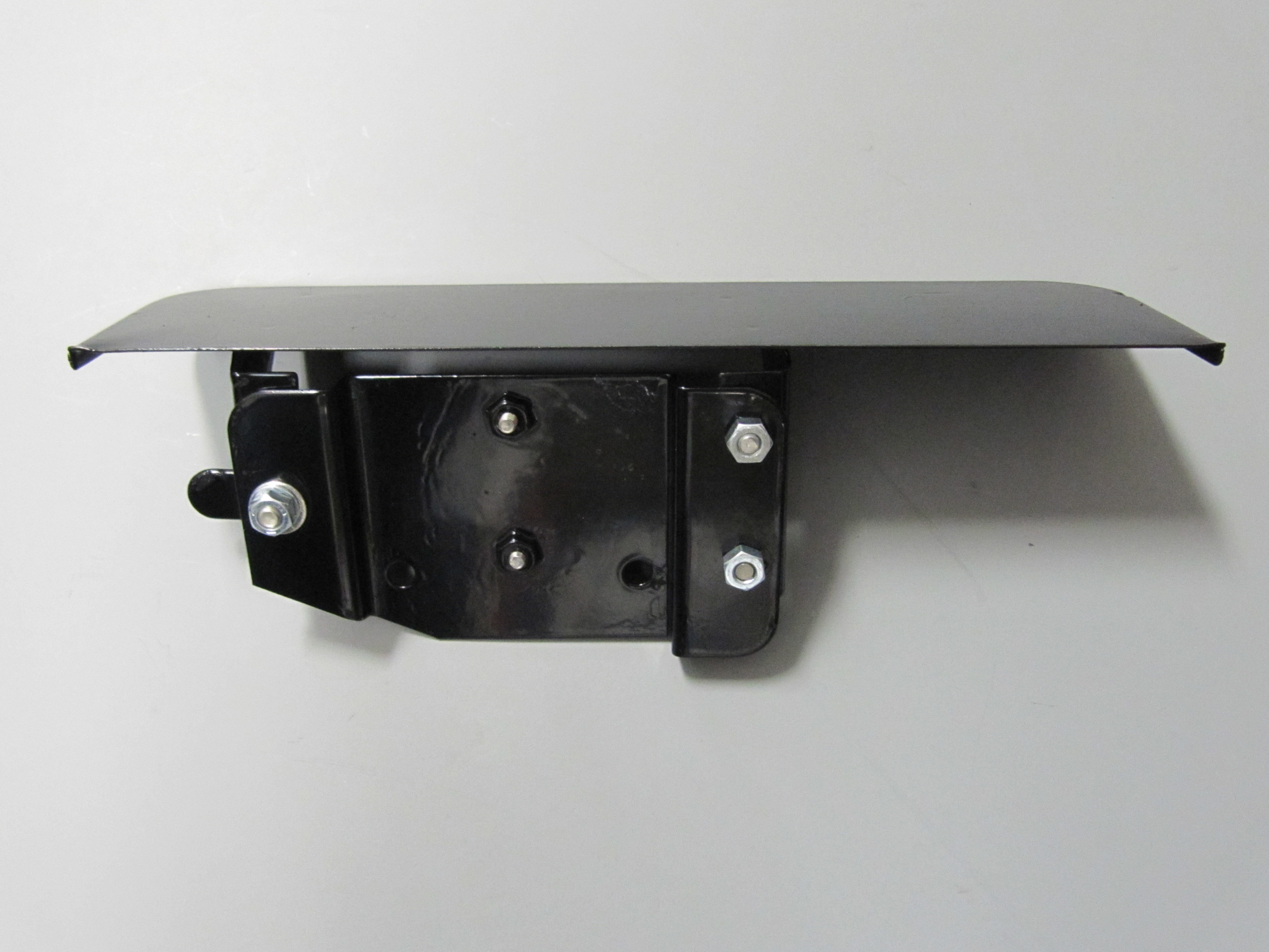
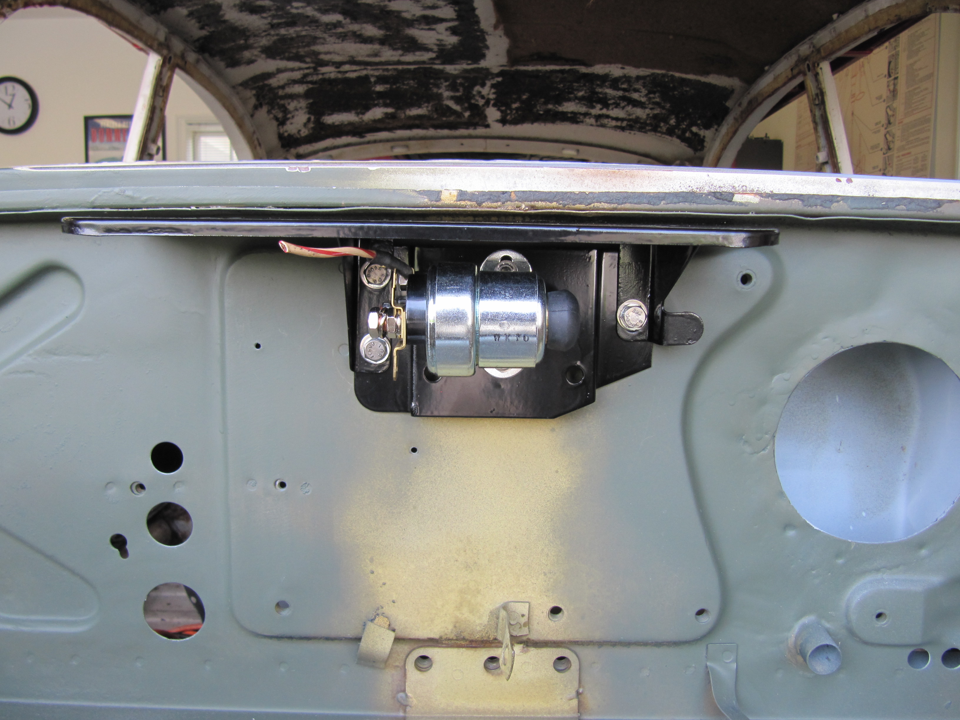
As shown in the video, and in the image below, the rear door regulator mounts with six slotted 1/4″-28 x 5/16″ pan head machine screws.

LH Rear Door Window Regulator Mount and Lock remote Control

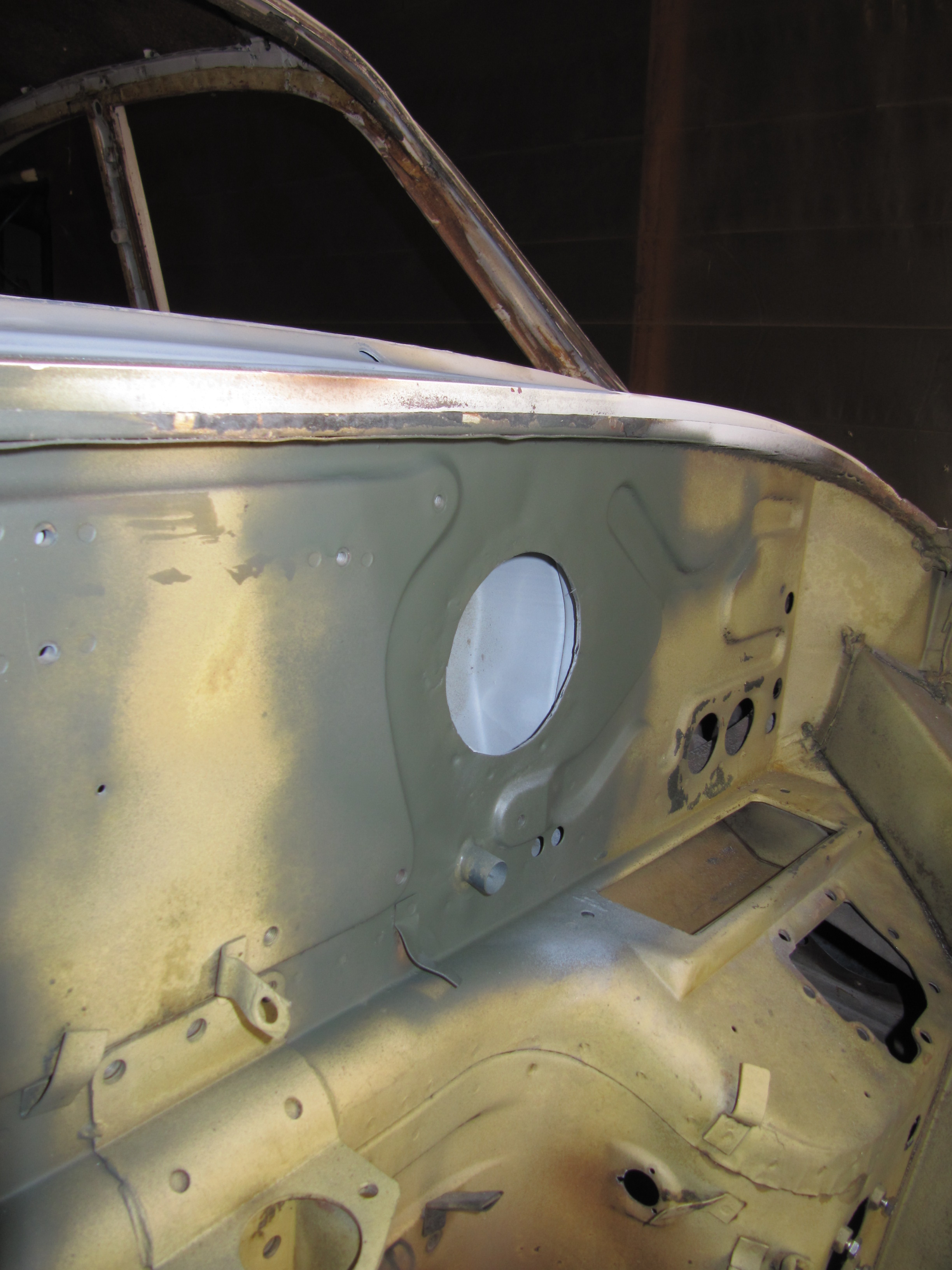
While the front door regulator mounts with four slotted 1/4″-28 x 5/16″ pan head machine screws as seen in the image below:

RH Front Door Regulator Mount with Four Screws

And, the spring/crank end of the regulator on the front door also mounts with four slotted 1/4″-28 x 5/16″ pan head machine screws:

RH Front Door Regulator Spring Mount with Four Screws

LH Front Door Window Regulator with all eight Mounting Screws

Installing Window Glass and the Window Frame

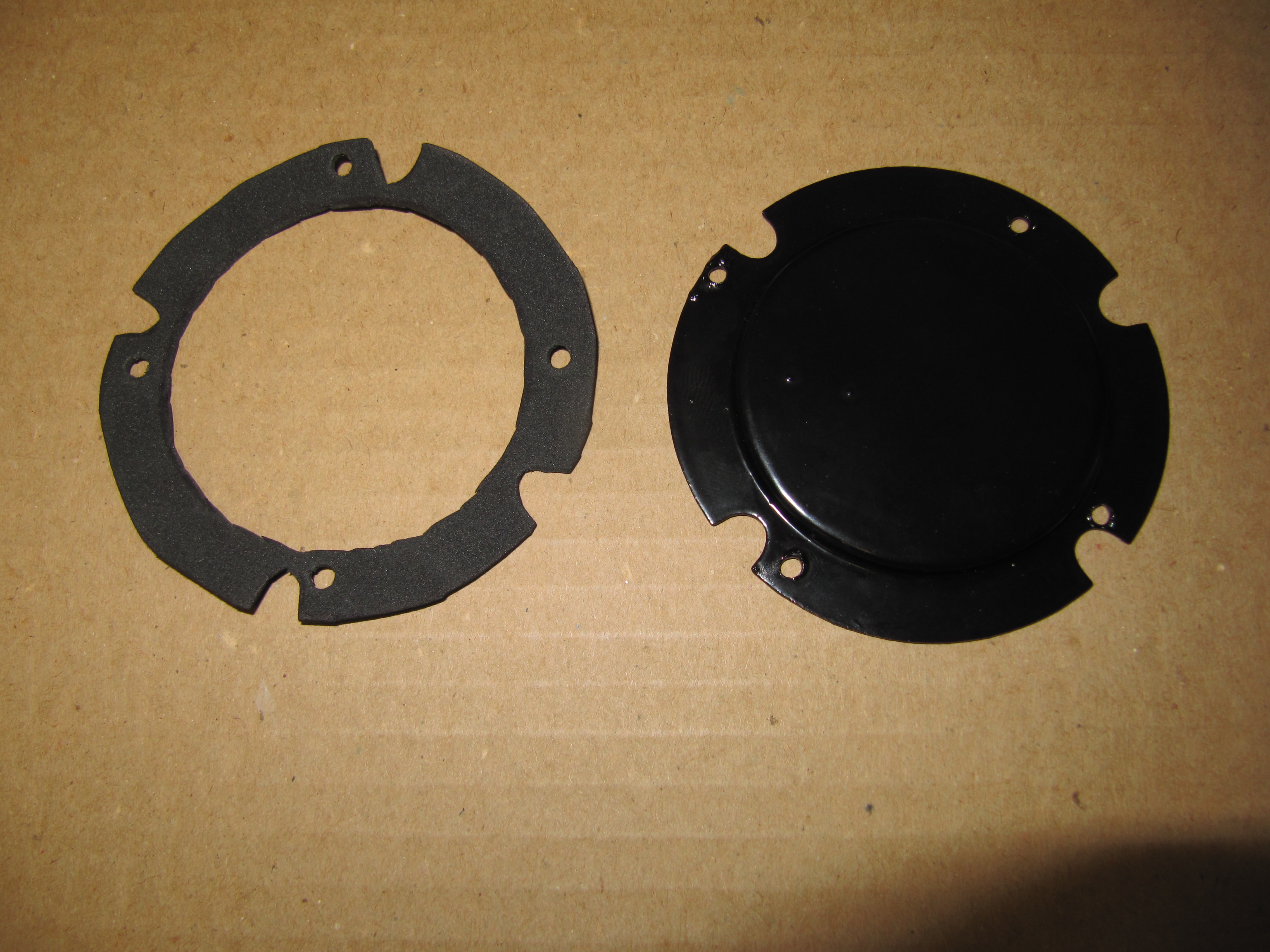
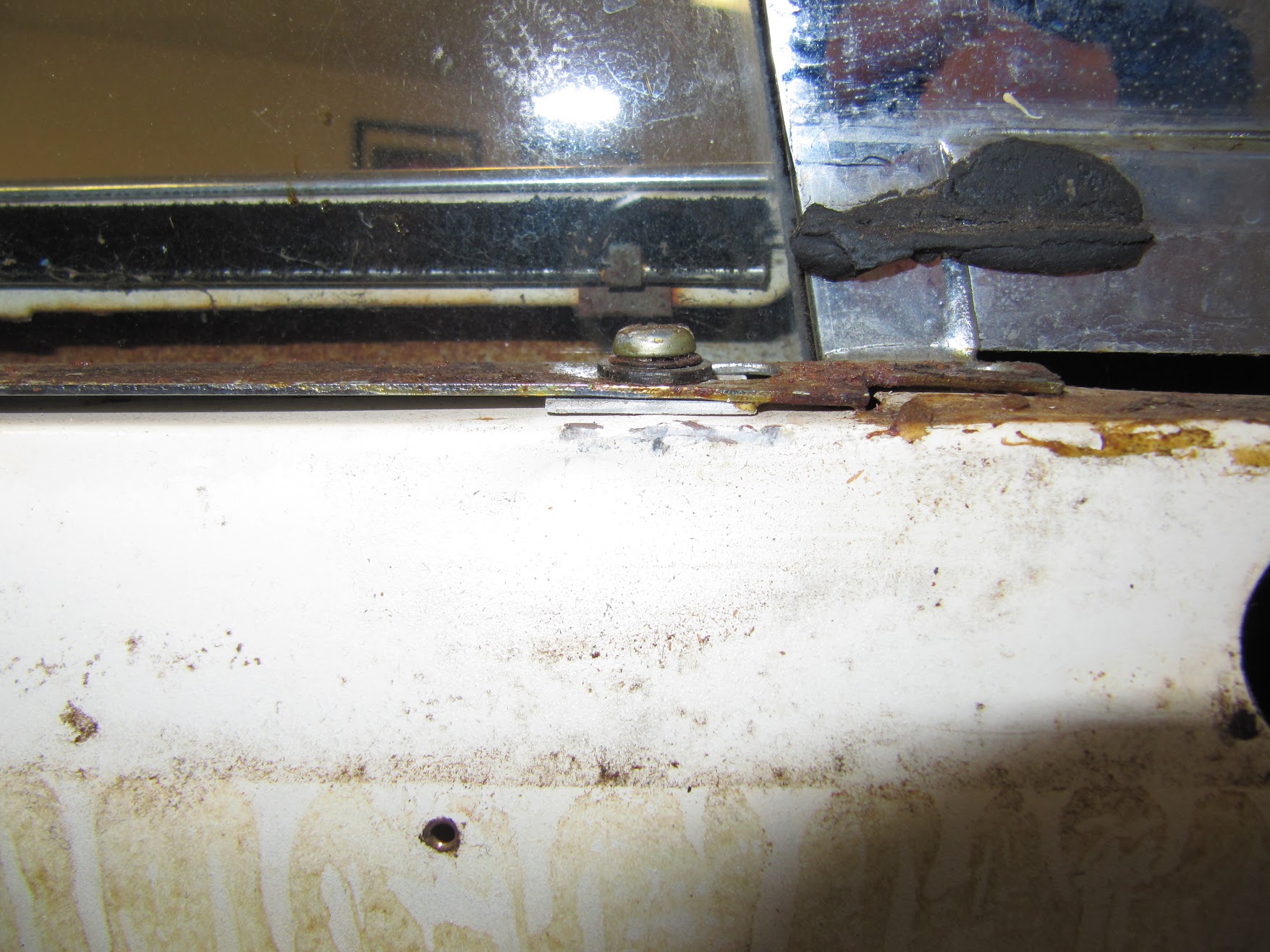
Before the window frames are installed, the four clips securing the weatherstripping to the interior side of the outside edge of each door need to be  pushed onto the door. The image below shows the clips when I removed the window frames from the car:

Four Clips to Secure Weather Strip to Outer Door Edge

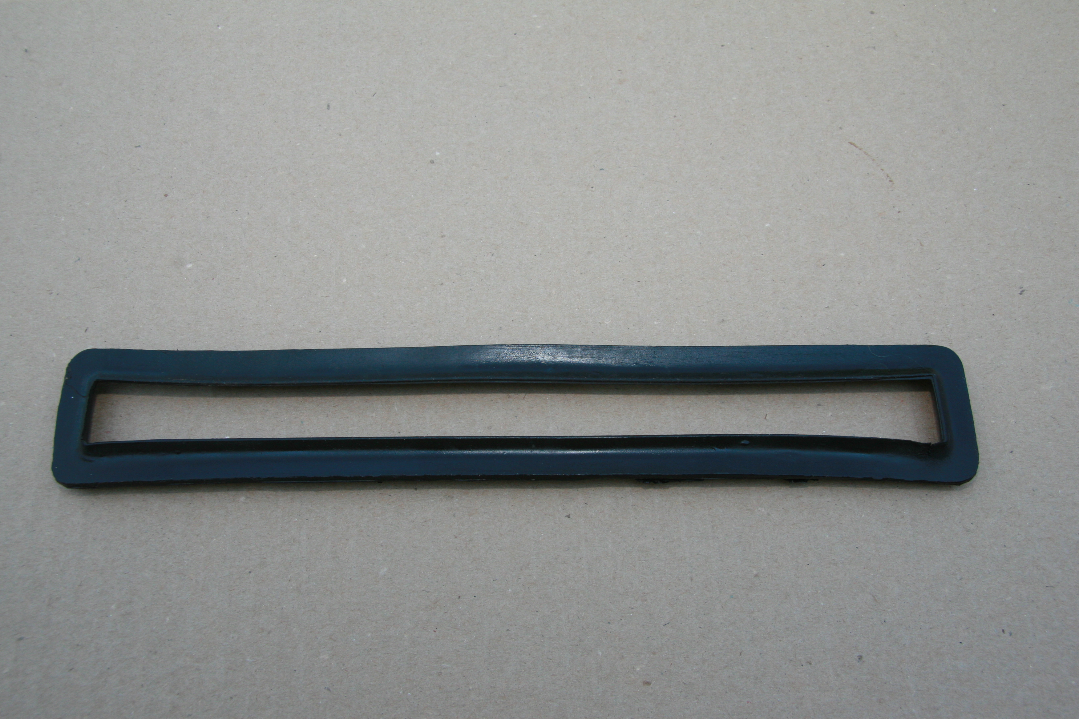
This image shows a section of the the weatherstripping in place and secured to the mounting clip:

Door Weather Strip and Mounting Clips

The image below shows a front window glass with the regulator “wheels” in the window channels 

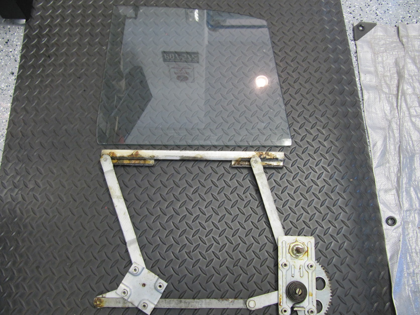
Front Window Glass and Regulator

The image below shows a front window frame with the lower mounting points on the legs of the frame:
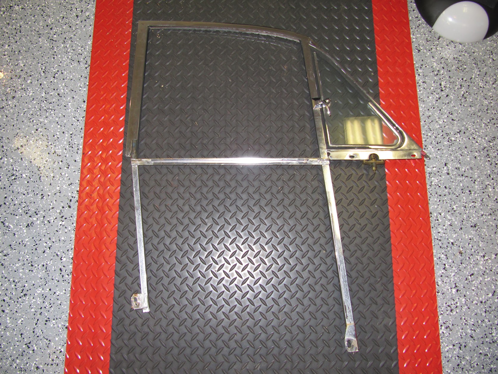
Front Window Frame

This process is also best described with a short video:

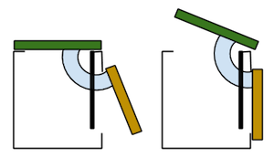
With the front window the procedure is the same except that the tracks are initially in front of the regulator rollers and one pushes the window rearward to advance it onto the rollers. This graphic shows the window frame sliding into the regulator:

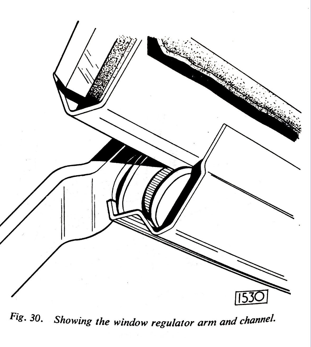
Window Mounting to Regulator

The Service Manual has a nice graphic illustration that shows the window frame securing points once you have the frame positioned in the door.

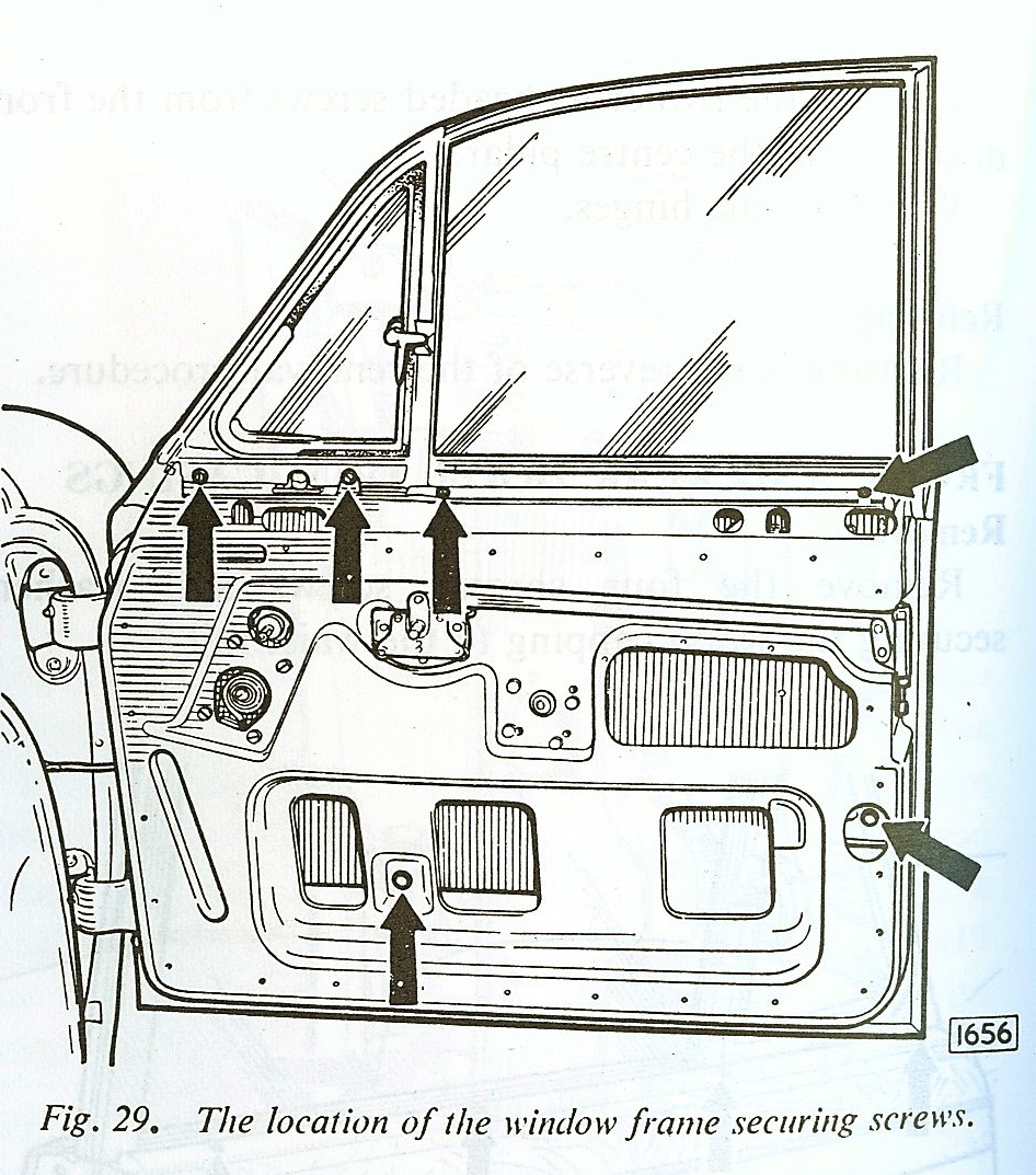
Window Frame Securing Screws

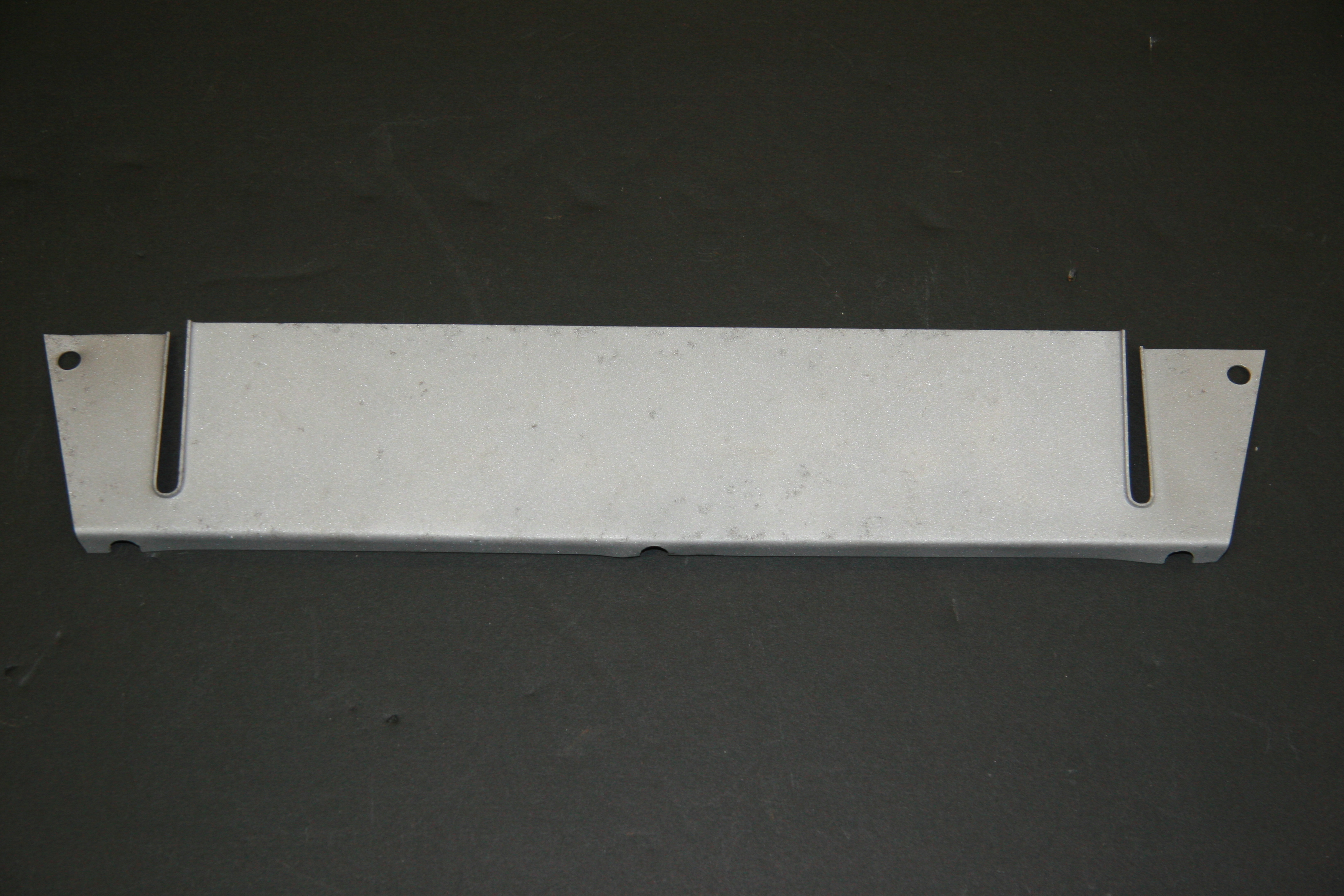
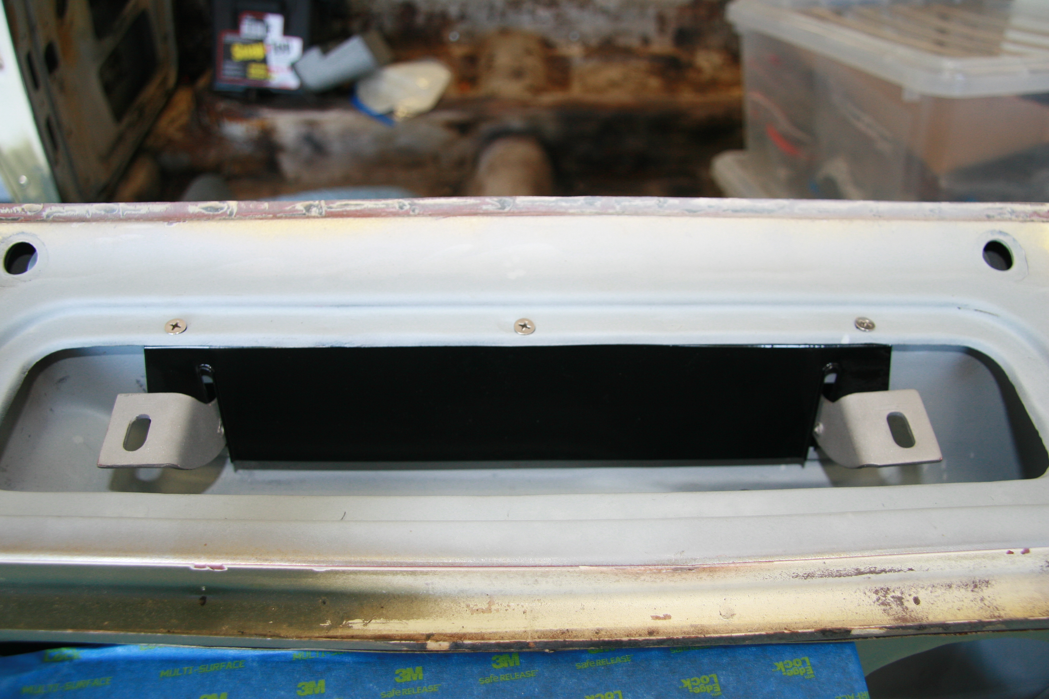
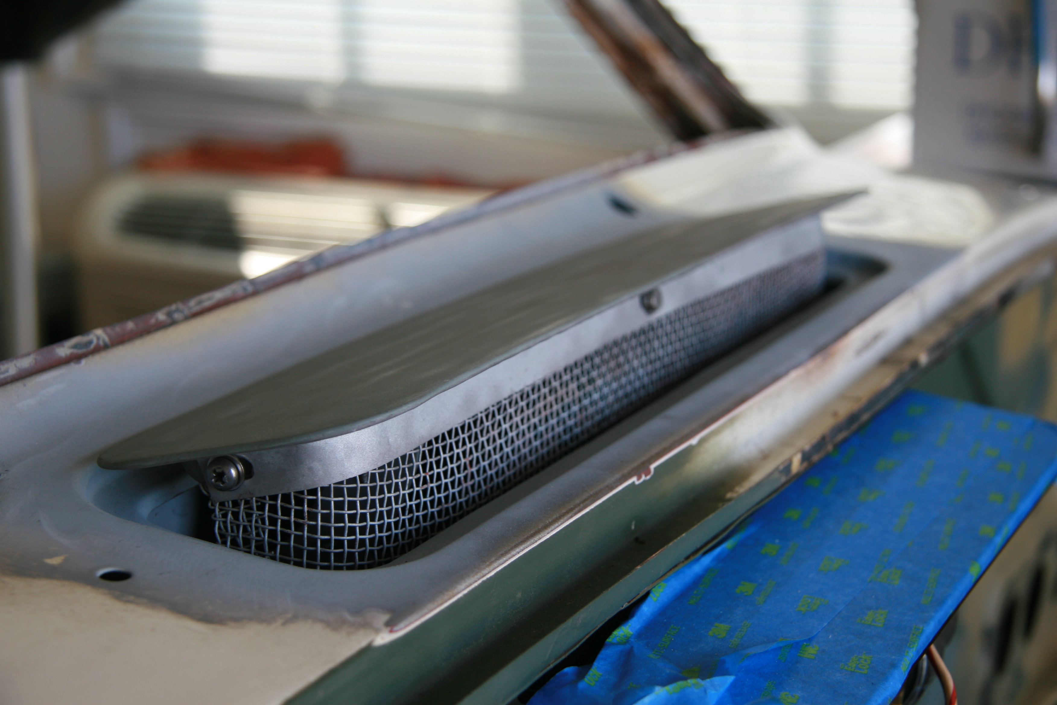
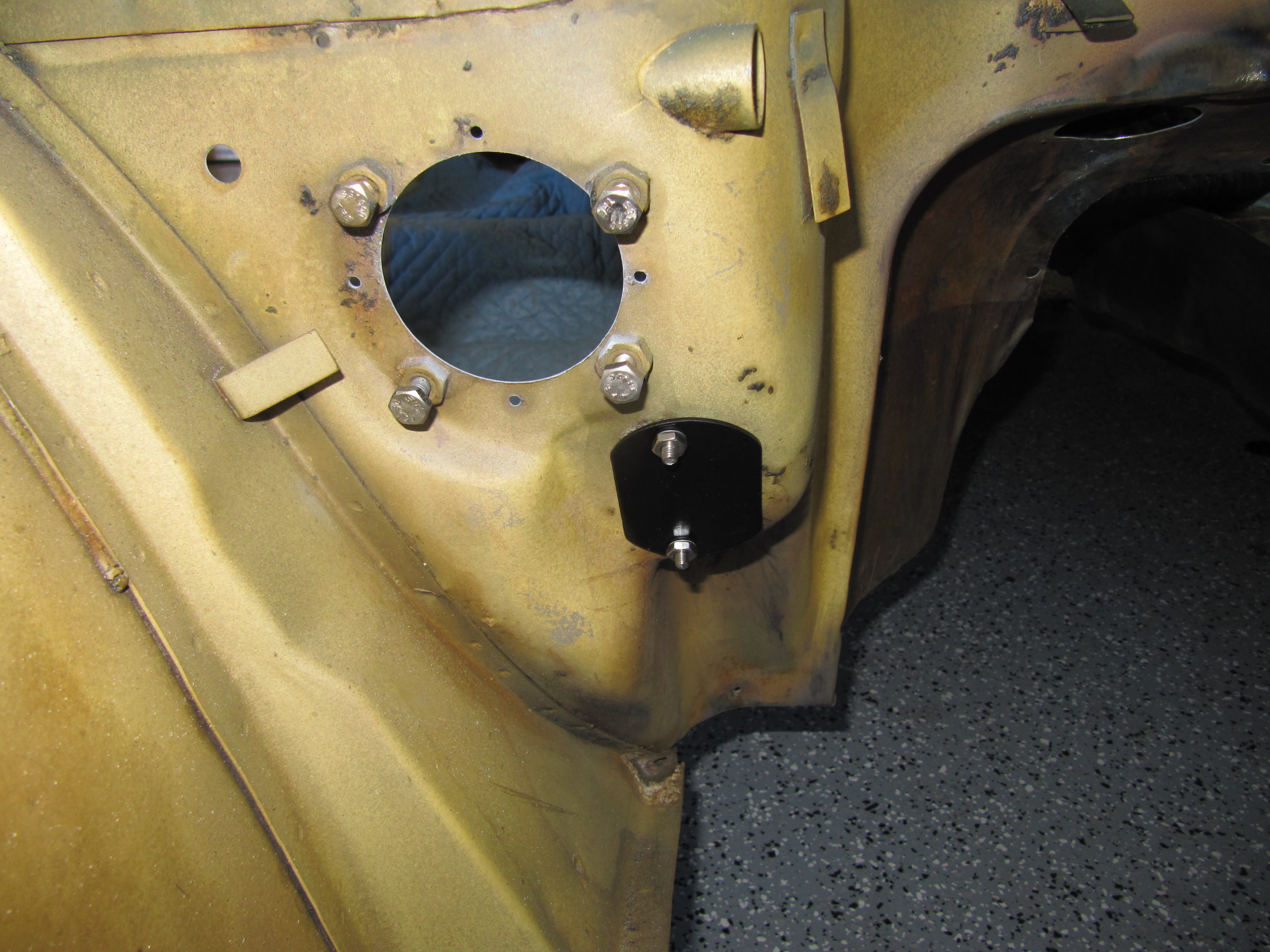
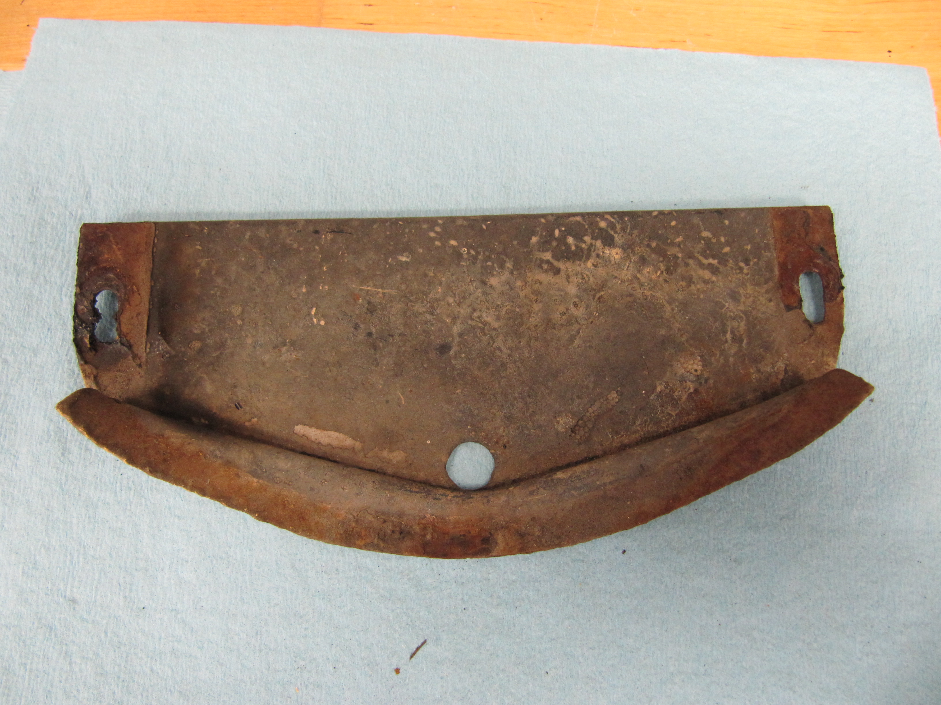
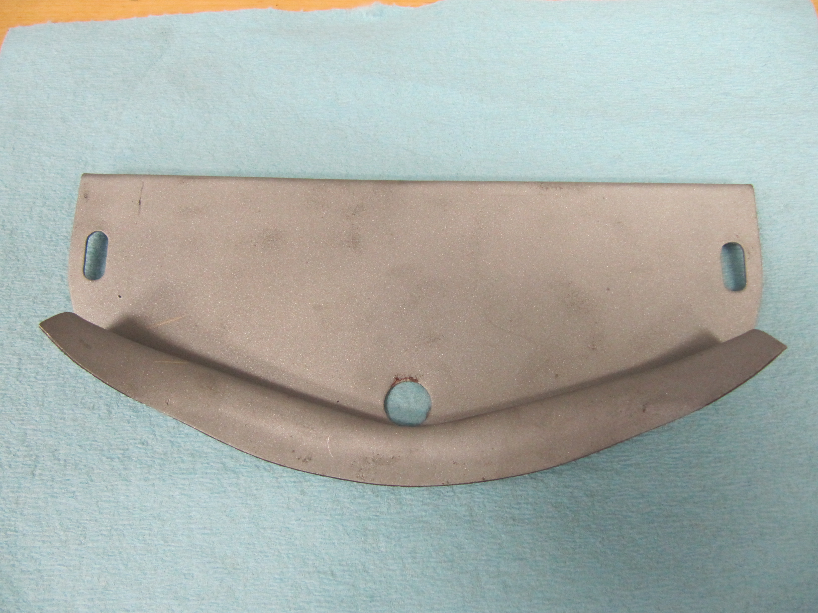
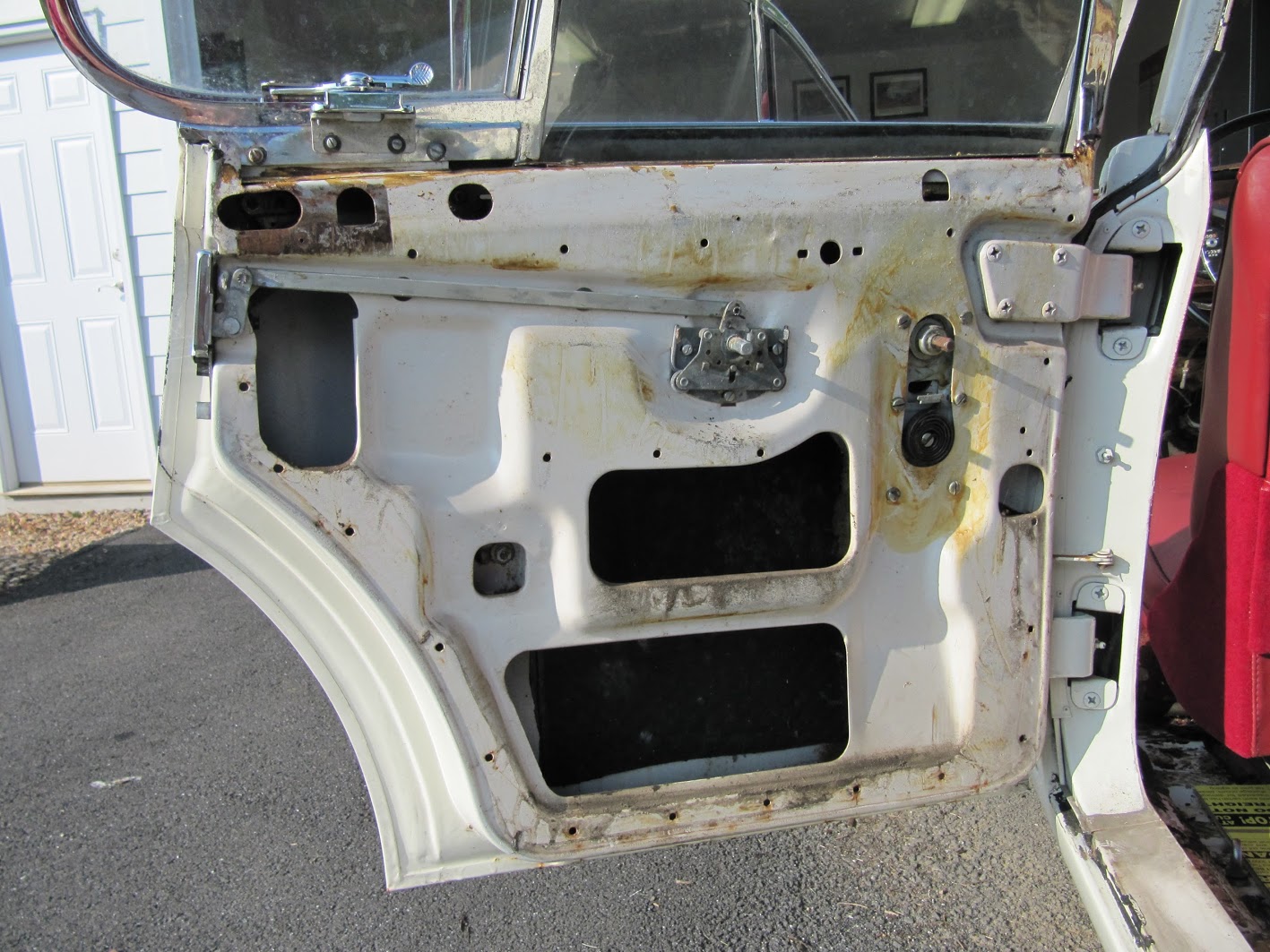
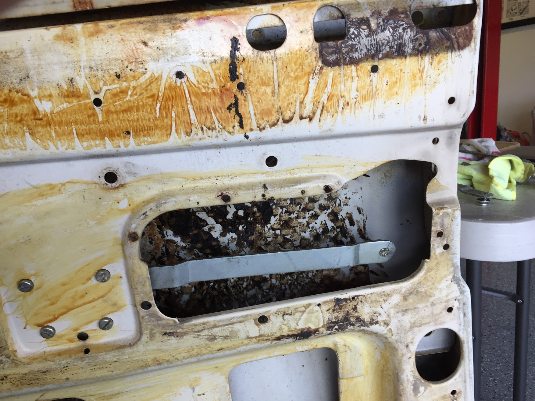
Before the window frames are secured to the doors, the Service Manual indicates that a layer of sealing compound should be placed on the door frame just below the  front and rear ventilators. I refer to this material as dum-dum made by 3-M. I will use a home made rubber gasket probably combined with dum-dum to help seal the area and keep water out. This is an example of what I found upon taking the window frames out of the car:

Dum Dum Sealer Below Window Frame

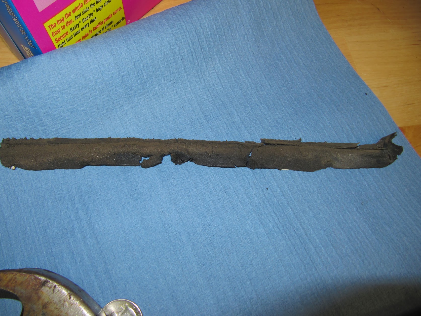
Dum Dum Window Frame Sealer


Each of the four door window frames is secured at the top of the door with four slotted #10-32 x 3/4″ pointed pan head machine screws. The mounting points for the rear doors are slightly different than the front doors as shown in the graphic, but all doors use the same number of screws. The window frames can also slightly slide rearward or forward for proper fitment. These screws should be loosely fitted to the door and window frame, but not tightened yet.

Window Frame Mounting Screws #10-32 x 3/4″

Front and Rear Adjustment of Window Frame

The height of the window frame is adjusted with the insertion of special shims, or packing pieces as they are called in the Service Manual, as needed. On my car, two sizes of shims were used. 

Window Frame Mounting Shims

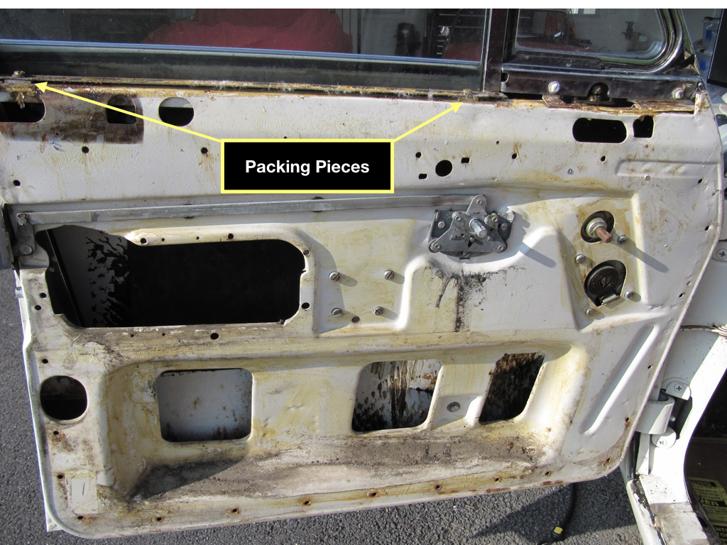
Window Frame Packing Pieces

LH Front Door – Rear of window used one packing piece; the front of the window used two packing pieces of different sizes.

RH Front Door – Rear of window used two packing pieces of the same size; the front of the window used two packing pieces of different sizes.

LH Rear Door – Rear of window used one packing piece; the front of the window used one packing piece.

RH Rear Door – Rear of window used one packing piece; the front of the window used one packing piece.

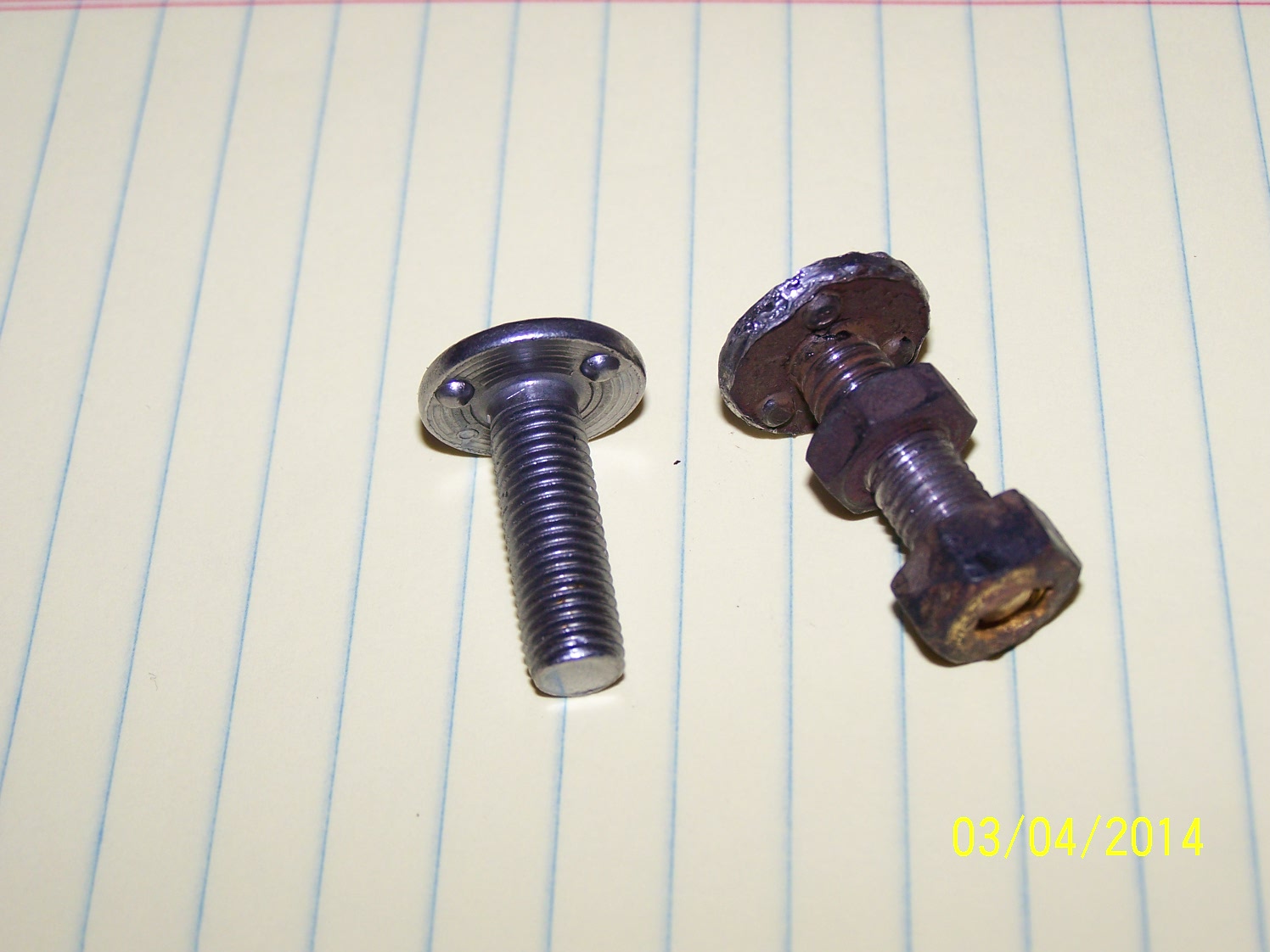
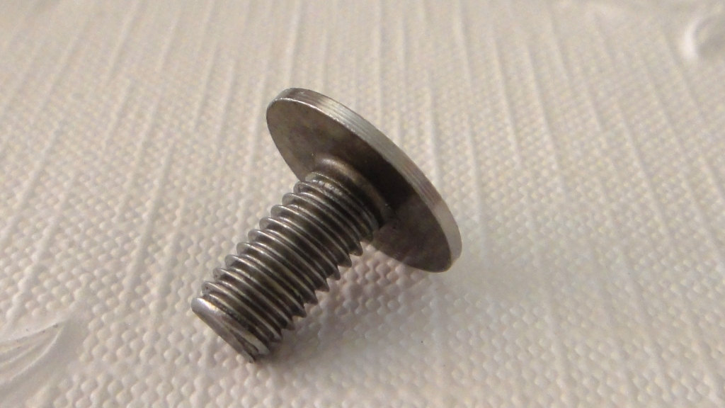
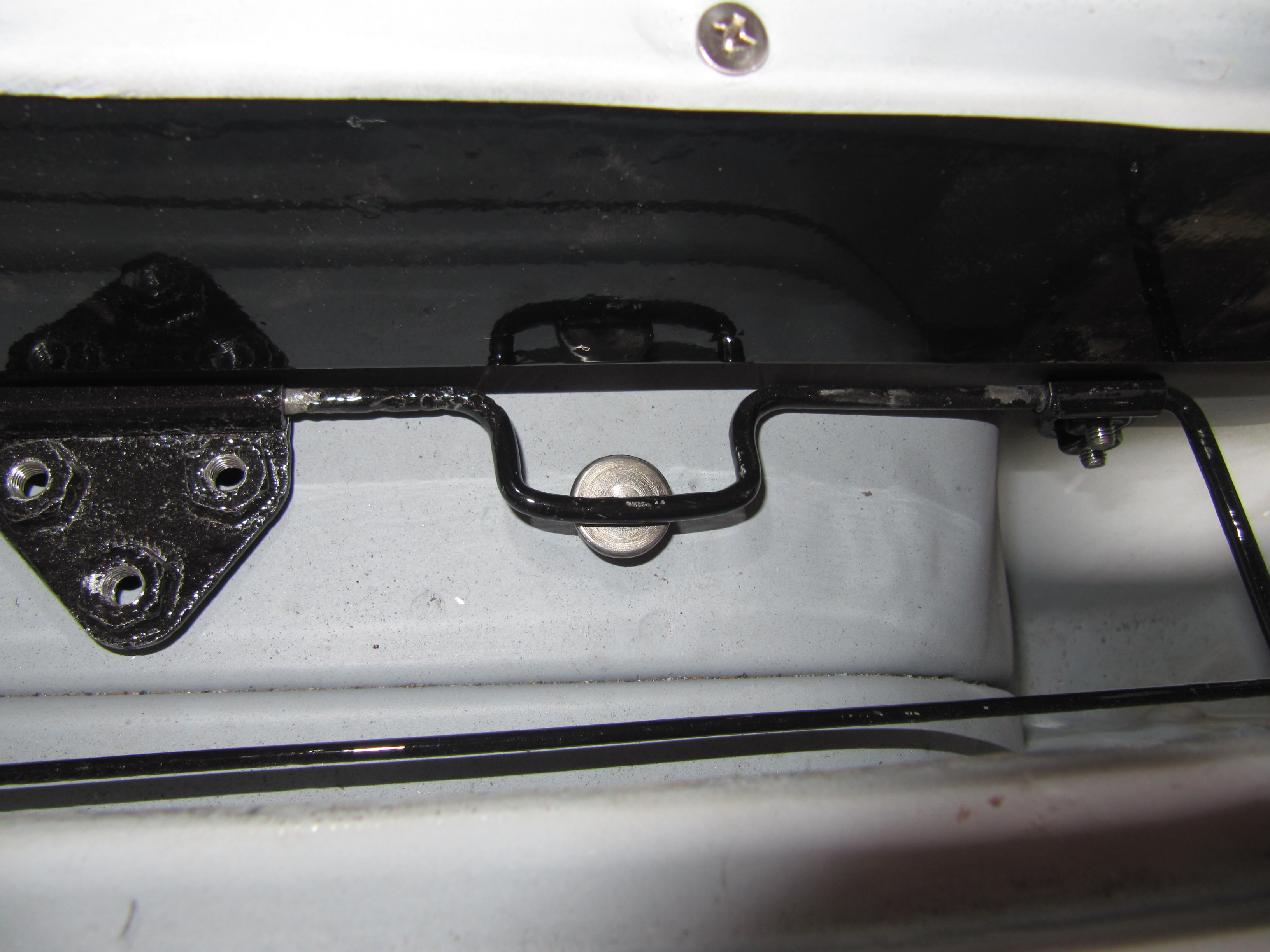
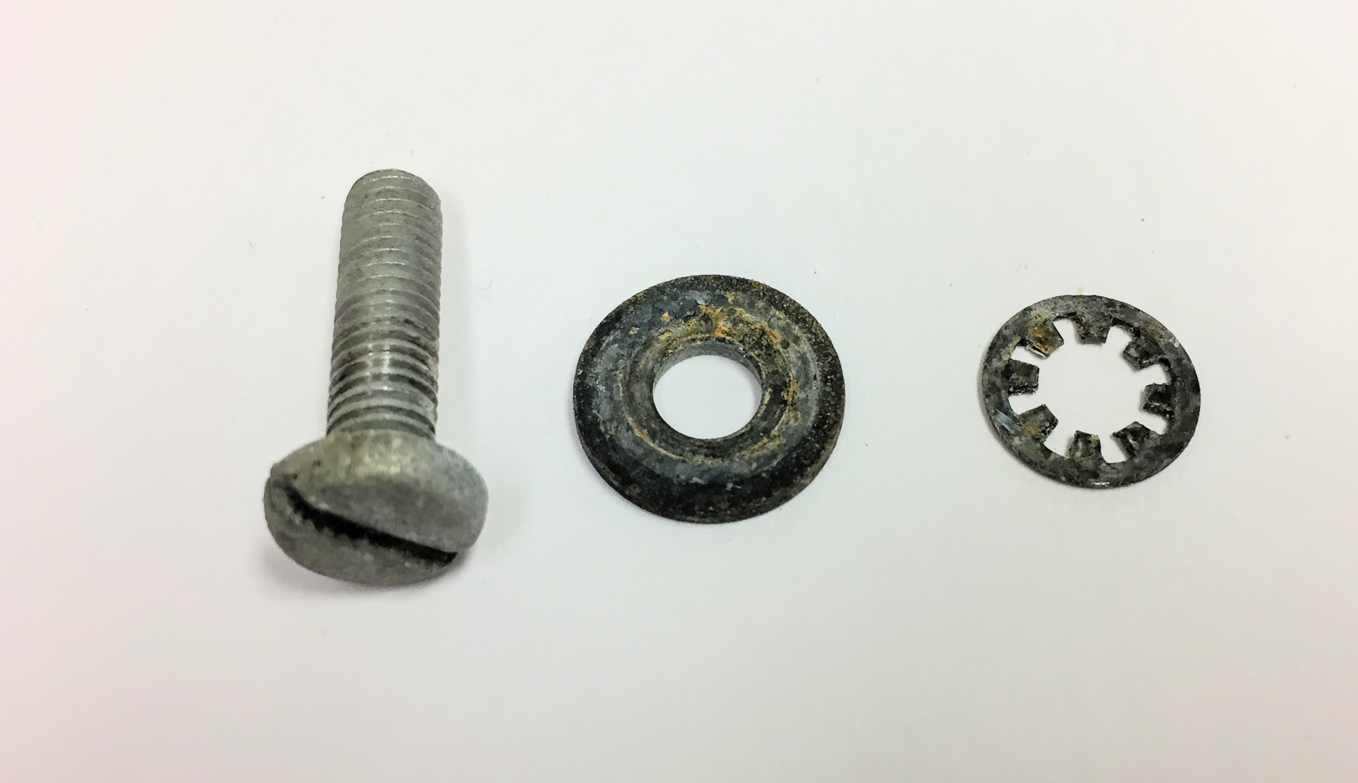
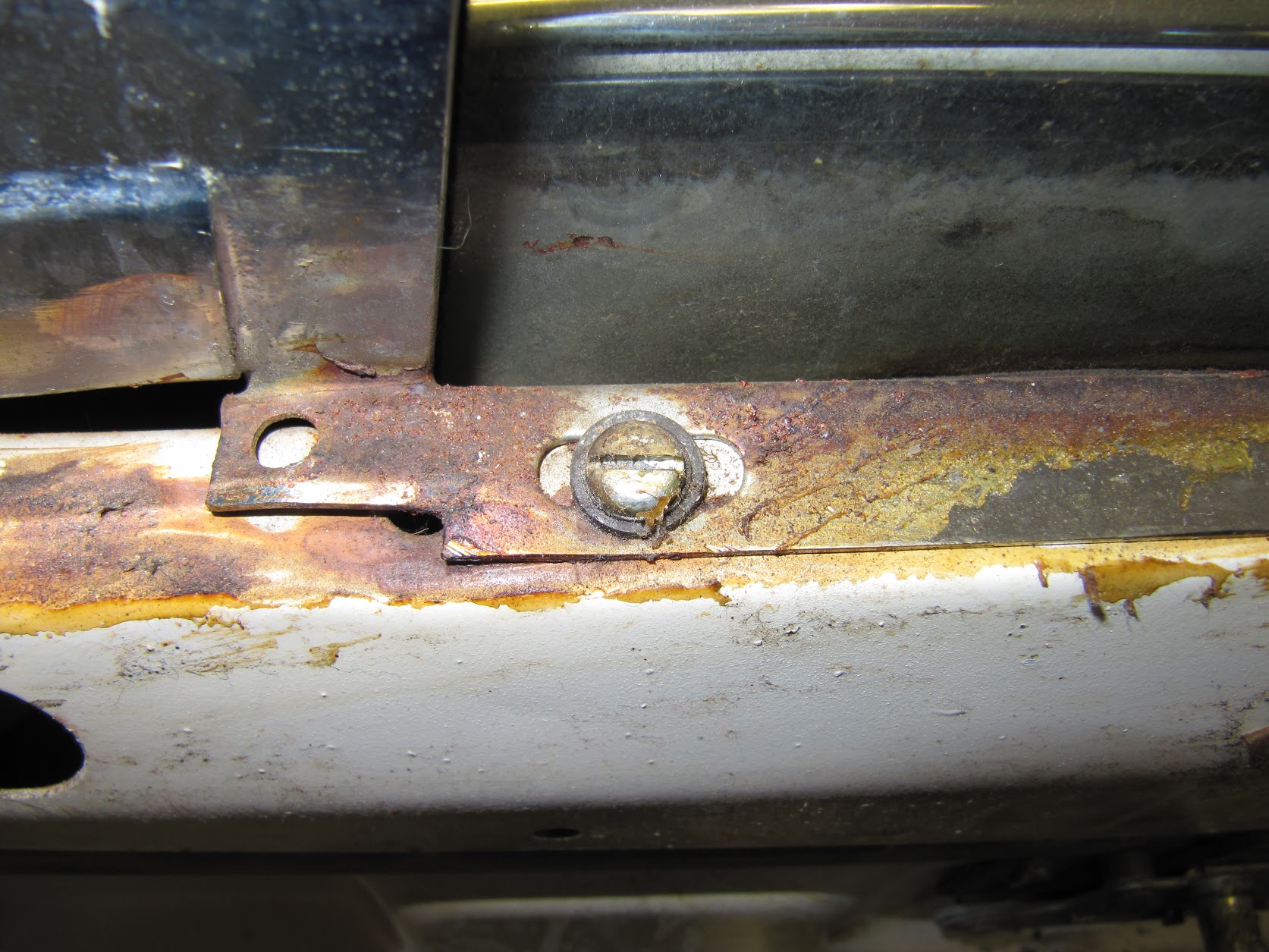
Once the window frame height seems to be right, the two lower securing points are fastened with a single 1/4″-28 x 1-1/4″ hex head bolt with a serrated washer and plain washers. Originally wooden discs or “packing pieces” were used at the lower leg fastening points to tilt the top of the window frame inward toward the rubber door seal. My car actually had a combination of wood and some hard rubber packing pieces. My wooden packing pieces were deteriorated and I will be using 1-1/2″ diameter nylon spacers with 1/4″ diameter center holes as replacements.

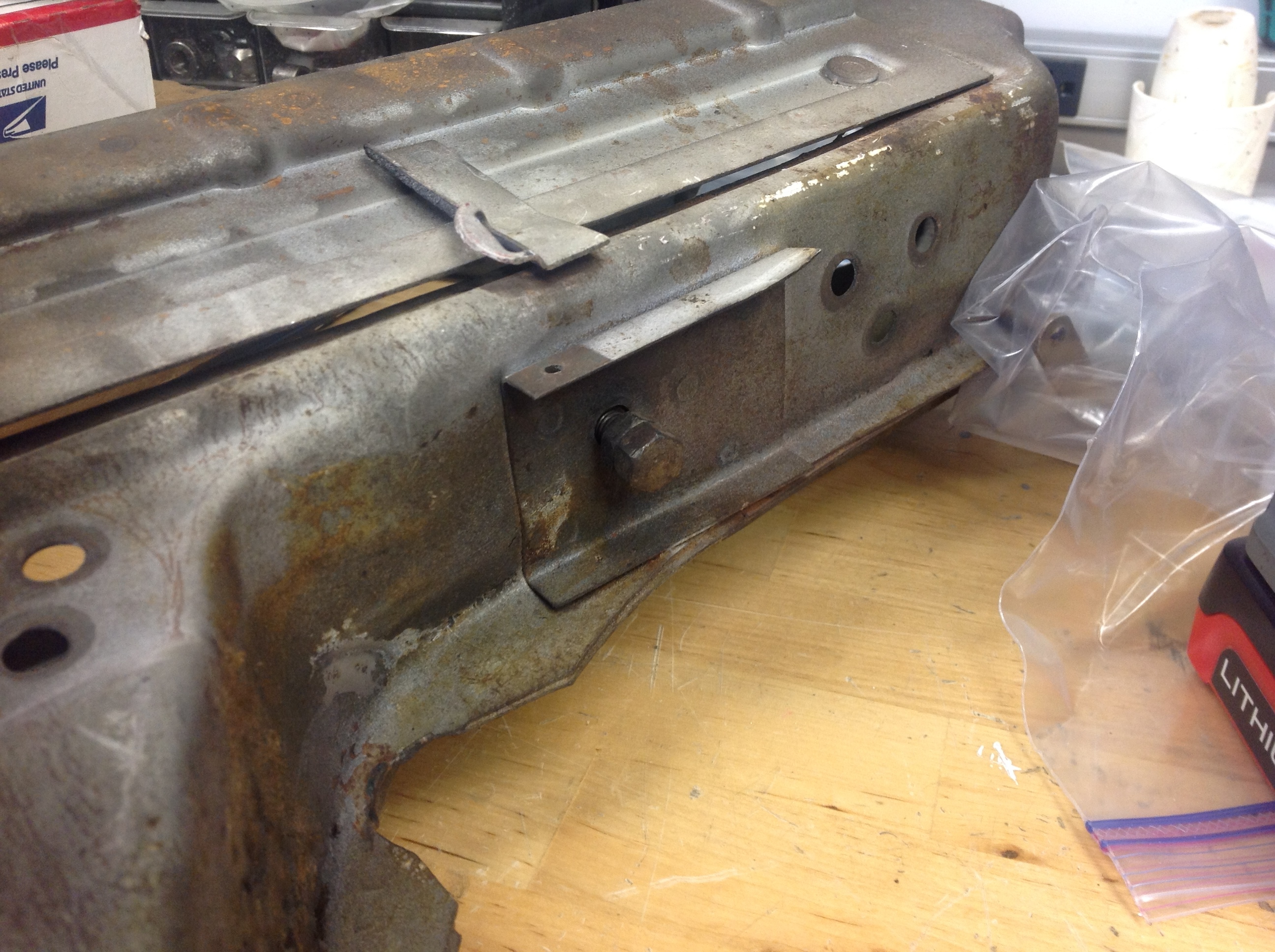
Once the window frame is in the proper position front to back ( “The window frame should clear the front screen pillar by 1/16”), the Service Manual instructs that the window frame post lower mount, with its packing pieces, farthest away from the door hinges should be tightened first. Then refit and tighten the front lower mounting point. Finally tighten the four pan head screws at the window frame top mounting points.

Original Window Lower Packing Pieces and Mounting Point

Original Window Frame Upper Mounting Screws and Lower Spacers with Bolts

Modern Window Frame Lower Spacers and Mounting Bolts

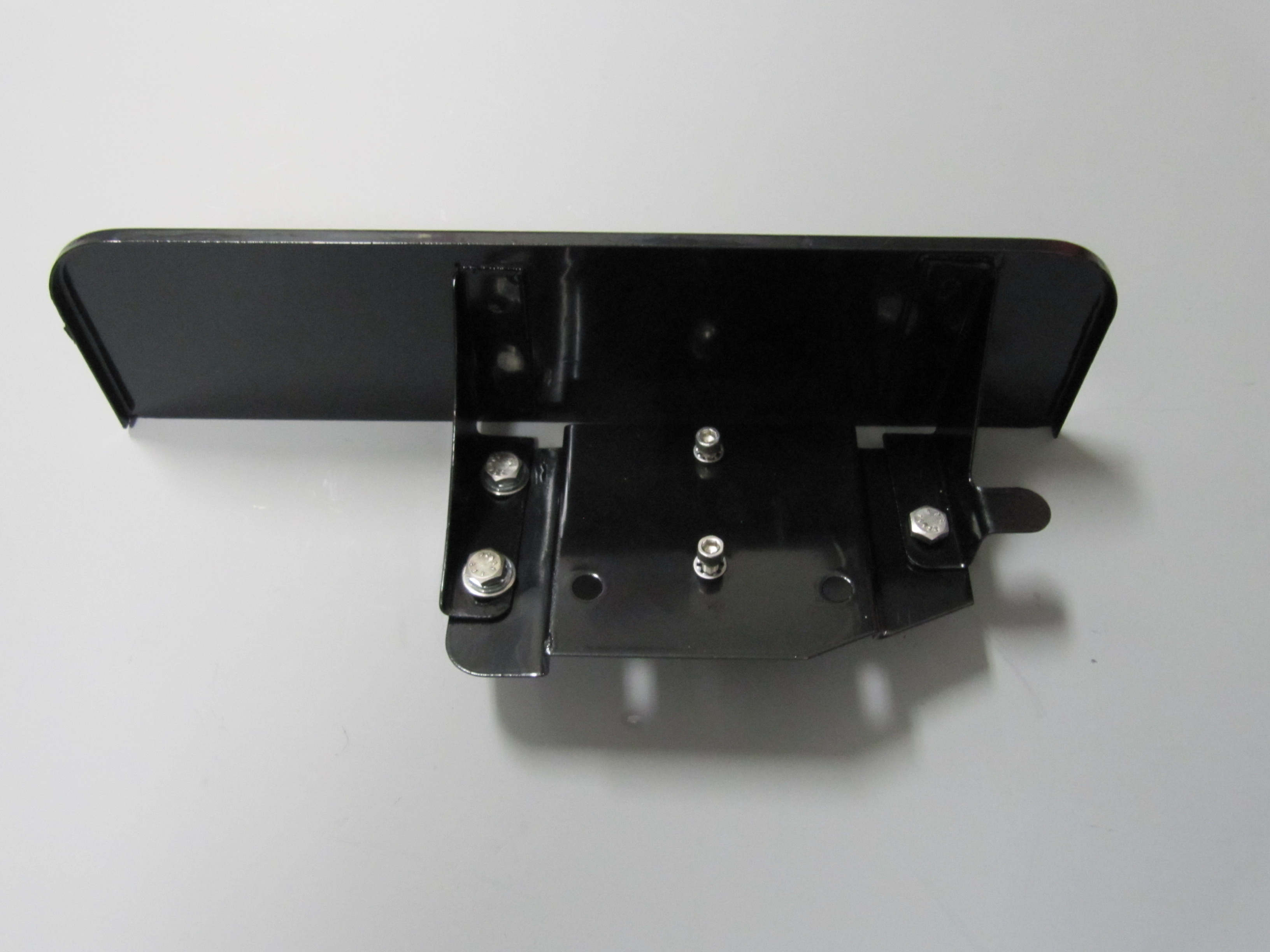
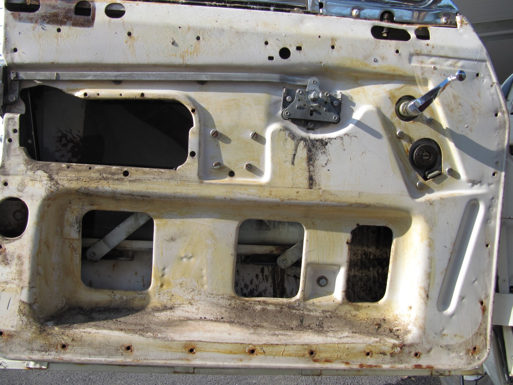
After the regulators, window glasses, window frames, weather stripping, and sealants are installed and the frames are properly adjusted the next to last step of the process will be to reinstall vinyl around the doors moving parts and to apply plastic sheeting to keep water inside the door and not in the interior! These photos show the original application:

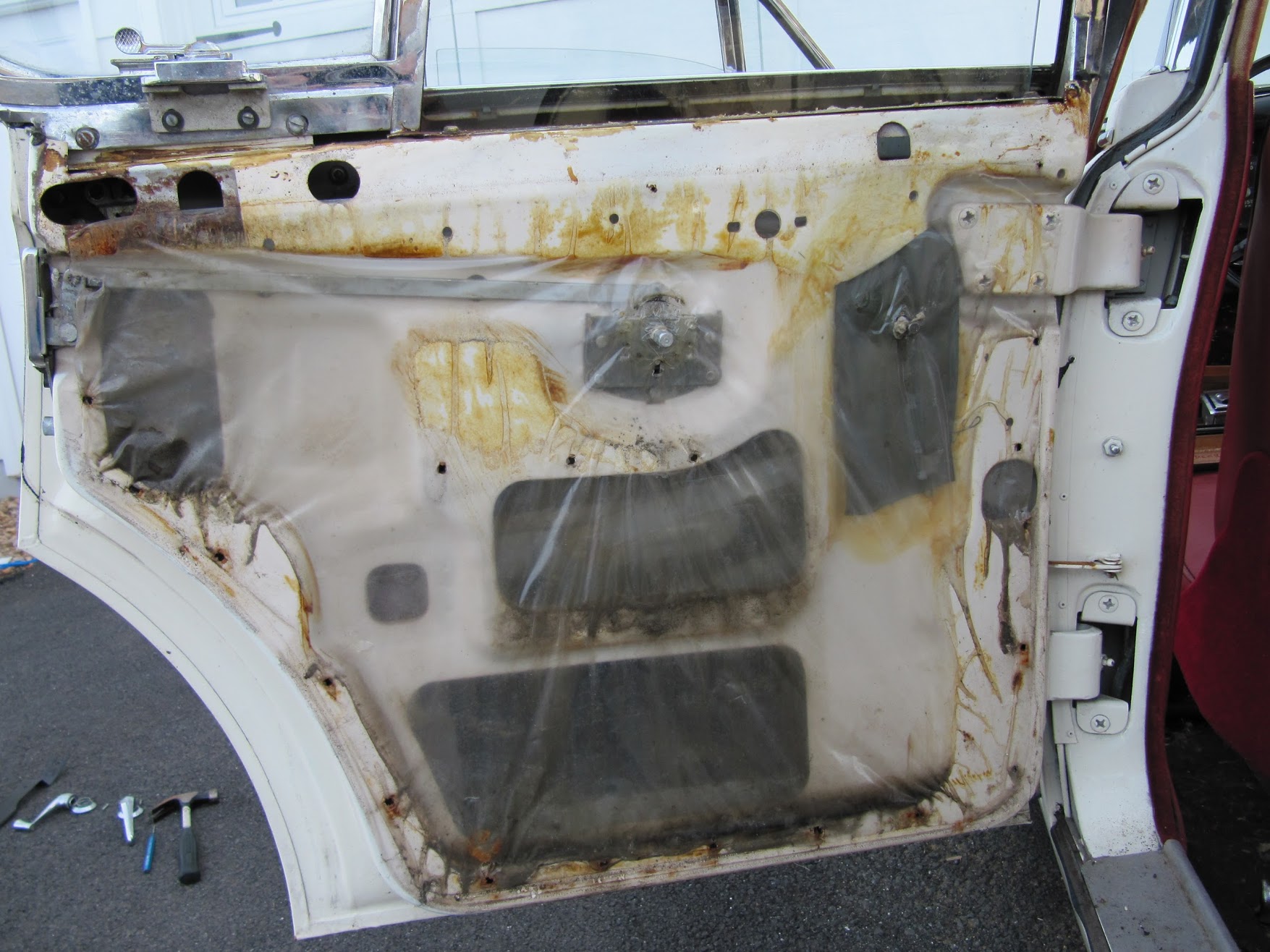
Rear Door Plastic Sealer Sheet, Vinyl Anti-rattle Cushions

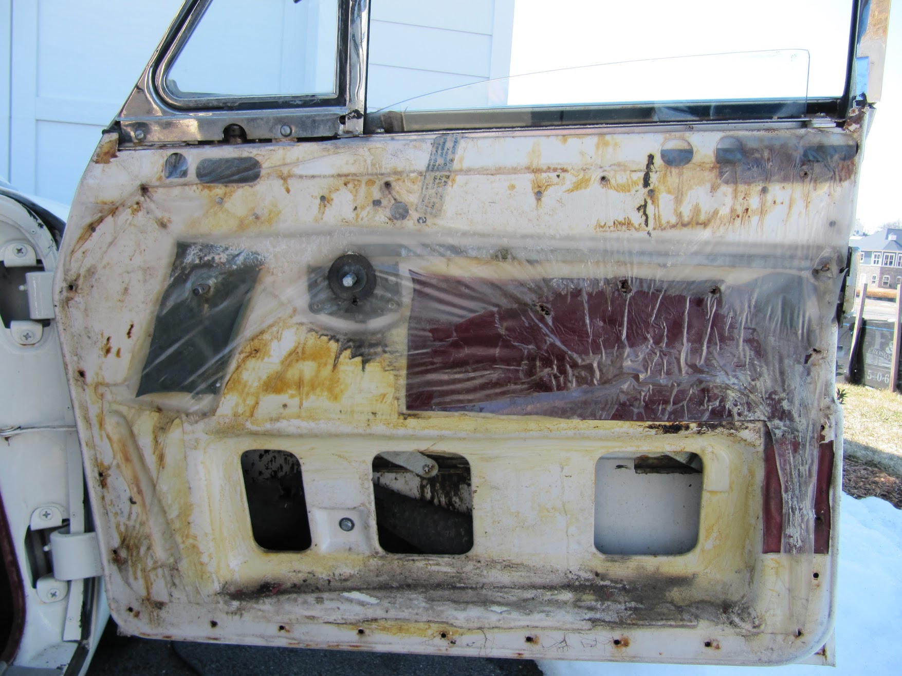
Front Door Plastic Sealer Sheet, Vinyl Anti-rattle Cushions


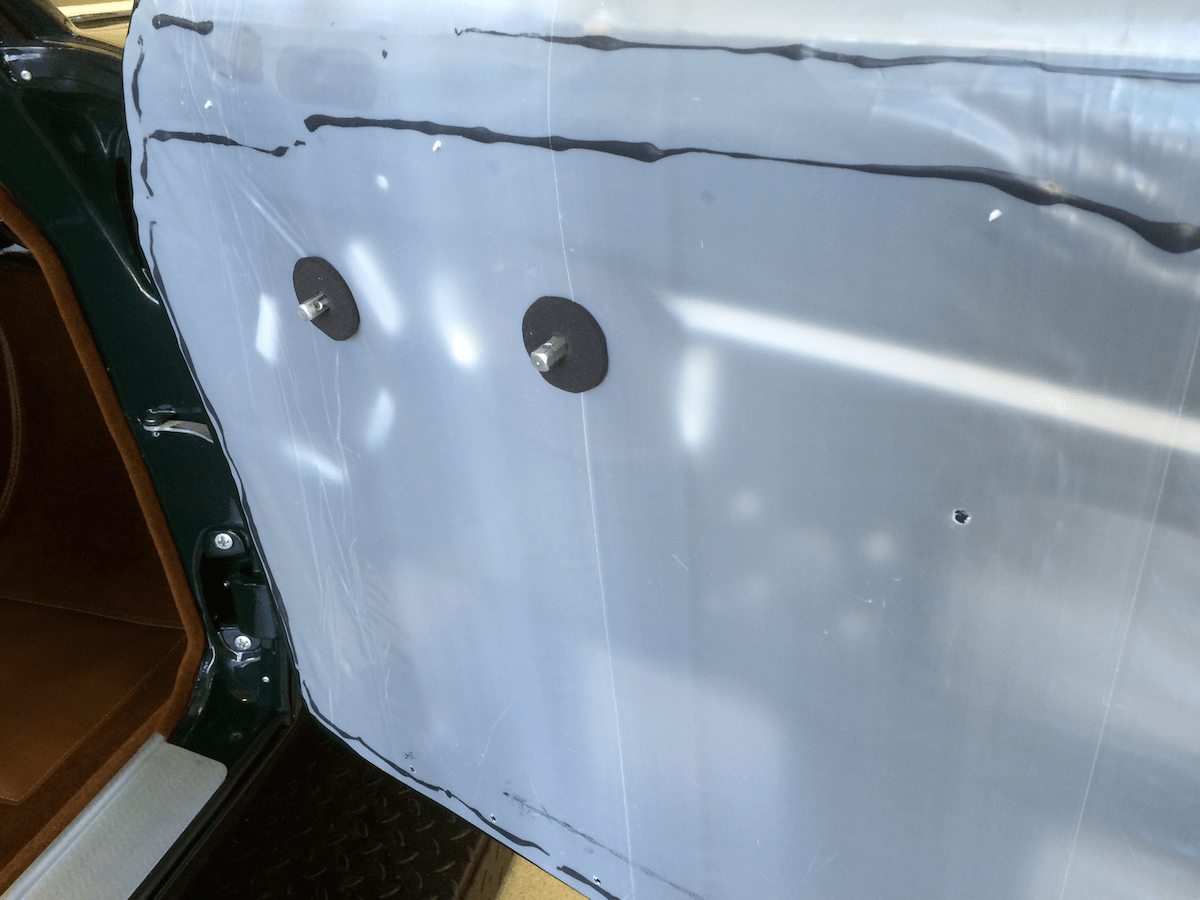
Eric Kriss provided an excellent explanation of this process on his Jaguar MK2 Restoration site. http://fairislepress.com/WP/?p=10706 He suggests that Jaguar placed the vinyl protectors to keep the window and door lock mechanism from fouling the plastic sheet. As Eric did, I will make some new ones using the old as patterns and glue them to the doors. Eric used a 4 mil plastic sheet with 3M 08621 Window-Weld 5/16″ Round Ribbon Sealer to fix the plastic sheets to the doors. Having used this material before I know that it is pliable, very sticky and reversible. Eric applied the ribbon sealer to the door and then pressed the plastic sheet to it using a rubber roller. I will do the same. This is a photo taken from Eric’s site: 

Eric’s Door Plastic Seal Sheet

The next step is to install the foam rubber cushions that fit to the window cranks and door handles before the casings go on. Again, this photo is from Eric’s site.

Foam Rubber Buffers at Handles

Finally, it is a matter of installing the door trim casings and the window crank handles and the door handles.

I will post more about this later. But for now I just want to record that it looks like I will need about 75″ of window channel track felt for each of the rear door windows and about 80″ for each of the front door windows.


Scuttle Ventilator

 Scuttle Ventilator Assembly

Ventilator Concept

My fellow MK2 restorer Eric Kriss has a very nice diagram and explanation of its workings on his Blog. With all credit to Eric, this is an excerpt from his post on the topic:

Jag Scuttle ventilator

Jag Scuttle ventilator


“The beloved Jaguar scuttle ventilator, probably designed by Rube Goldberg himself, works in a somewhat counter-intuitive way. The vent lever operates a dual lid system.

When the top (horizontal, colored green) vent lid is closed, no fresh air enters the passenger compartment, but the vertical lid (colored tan) is open! When the top lid is open, the vertical lid closes, forcing fresh air into the scuttle plenum and out through the air distributor box.

Note that if the top vent lid is closed and the heater is running, hot air entering the plenum from the heater will also pass into the center instrument panel area. A rear ventilator shield (colored black) forces most of the hot air into the air distributor box, but this still warms the instruments … probably not a really great idea. Rain water can leak in the same way.”

Assembly Sequence

I did a trial installation of the Scuttle Ventilator Assembly in July 2014. The following sequence was used to install components:

  • Two door hinges
  • Weather shield
  • Torsion bar assembly, vertical race first
  • Operating arm
  • Scuttle lid
  • Lid mesh grille to lid

Scuttle Plenum

The plenum on my car was very rusty and given the location of the plenum it cannot be repaired in place. I was fortunate to locate a good used plenum and John Stefanik installed it for me. This effort also required some repairs to the firewall, and John accomplished all beautifully.

Plenum Firewall Repairs

Plenum Firewall Repairs

New "Used" Plenum Installed

New “Used” Plenum Installed

Operating Arm Assembly, for Scuttle Ventilator

The Operating Arm Lever and knob were in great shape. It appeared that the car was painted at the factory after the Lever was mounted as the exposed parts of lever were body white, while the rest of it was zinc. The Lever cleaned-up nicely and was zinc plated. The Arm assembly mounts to the body shell with four 1/4″ – 28 x 1/2″ hex head bolts with split washers. The knob polished well and I repainted the “VENT” lettering. It’s position is adjusted using a 1/4″ – 28 lock nut.

I assembled the Scuttle Ventilator and installed it as a trial for fit and operation. Everything worked beautifully.

Operating Arm Assembly, for Scuttle Ventilator Lid

Operating Arm Assembly, for Scuttle Ventilator Lid

After a little polishing and a lettering “touch up” with some white modeling paint, the knob for the operating arm assembly looked as good as new.

Scuttle Vent Operating Arm Knob

Scuttle Vent Operating Arm Knob

Operating Arm Assembly, for Scuttle Ventilator Lid Trial Fitting

Operating Arm Assembly, for Scuttle Ventilator Lid Trial Fitting


Torsion Bar Assembly for Ventilator Lid 

This piece was very rusty but after soaking in a rust treatment, blasting with aluminum oxide, and the application of heat with a torch to the pivot points, I got it operational and I believe that it is strong enough to be used as is. I painted it with POR-15 and will hope for the best. The part is not available from the usual vendors.

I installed it as part of the trial fitting of the scuttle ventilator assembly and while it is not visually pretty, it appears that this part has been successfully saved. The Assembly mounted with five 1/4″-28 x 1/2″ hex head bolts, shake proof and flat washers. It is easiest to mount the vertical brace (to the left in the image below) first and then the piece with the three bolts.

Torsion Bar Assembly for Ventilator Lid

Torsion Bar Assembly for Ventilator Lid

Torsion Bar Assembly for Ventilator Lid

Torsion Bar Assembly for Ventilator Lid

In the photo below, the weld stud that screws into the nut at the bottom of the plenum has not yet been installed. My fellow MK2 restorer and part hunter extraordinaire, Robert Seligman, somehow tracked down a source for the weld stud. http://www.jhpfasteners.com/5/16-weld-stud-with-projections-under-head-p-5614-l-en.html

Apparently the stud was screwed in an upward direction to create more pressure if it was needed on the torsion bar assembly. Oddly, the stud is double-nutted with the lower nut welded so as not to loosen.

New and Original Weld Stud

New and Original Weld Stud

Plenum Weld Stud

Plenum Weld Stud

Adjusting nuts on bottom of Plenum

Adjusting nuts on bottom of Plenum

Weld Stud Installed in Plenum to adjust Torsion Spring

Weld Stud Installed in Plenum to adjust Torsion Spring

Torsion Bar Assembly for Ventilator Lid Trial Fitting - Mounting Bolts

Torsion Bar Assembly for Ventilator Lid Trial Fitting – Mounting Bolts

Rubber Seal on Recirculating Door on Scuttle Face Panel

I was going to install a new rubber seal, but discovered that new stock is not obtainable. So I took a look at my original to see if it could be saved. I recalled that there were some tears in the rubber but I was hopeful. Upon close inspection I found not tears, but several places where mice had chewed and eaten the rubber. Those bastards eat anything – rubber seals and wire insulation have great nutritional value I am sure!

Rubber Seal on Recirculating Door on Scuttle Face Panel Rounded Side

Rubber Seal on Recirculating Door on Scuttle Face Panel Rounded Side

Mice Teeth Marks

Mice Teeth Marks

I checked into rubber rejuvenation and a German product called Gummy Pflege Stift was recommended.I ordered and tried it and found it to be quite good. The seal is now clean soft and pliable. The surface that mates with the door is in good shape so I think I will be able to use this seal.

Gummi Pflege Stift

Gummi Pflege Stift

Rejuvinated Plenum Seal

Rejuvinated Plenum Seal

Rear Shield for Scuttle Ventilator Assembly

I don’t know the proper name for this component of the assembly. But, I  media blasted it and had it powder coated. This piece is a little tricky (not hard) to install. It used three flat head 2BA 3/8# screws and square nuts originally. Square nuts are used because the flange on the piece is used to tighten the screws. I found it easiest the start the nut on each screw, push the piece under the scuttle but above the nut, and then tighten each screw.

Rear Shield for Scuttle Ventilator Assembly

Rear Shield for Scuttle Ventilator Assembly

Powder Coated Rear Shield for Scuttle Ventilator Assembly

Powder Coated Rear Shield for Scuttle Ventilator Assembly

Scuttle Assembly Shield Mounted to Scuttle

Scuttle Assembly Shield Mounted to Scuttle

Scuttle Ventilator Lid and Wire Mesh Grille

A couple of the mounting screws for my original lid broke when I tried to remove it from the car. Fortunately, I was able to locate another lid which worked fine with my original wire mesh grille. The lid is installed first then the grille is added. The lid attaches to the hinges with captive #10-32 machine screws which are quite long, perhaps 1 inch. The length is to facilitate the mounting process. As one can see in the image above, there is adjustment for and aft for the lid. I suppose washers could be used to raise the height of the lid if needed.

The wire mesh grille is mounted to the lid with three phillips head #10-32 x 1/2″screws. I found it easiest to insert the front center screw first followed by the side screws. The mesh grill is properly painted the color of the car.

Scuttle Ventilator Assembly Lid and Wire Mesh Grille - Trial Fitting

Scuttle Ventilator Assembly Lid and Wire Mesh Grille – Trial Fitting

The Scuttle Plenum has a drain tube at its bottom and a rubber drain hose is mounted to the tube. The drain hose simply drains to the ground below the car. The image below shows a trial fitting of the hose. Unfortunately, it is a bit difficult to make out in the photo. It is the large hose that exits to the transmission tunnel.Plenum Drain Hose


Body Panels and Trim

Body Panels and Trim

Cover and Blanking Plates

Of course, there are many large and small components that comprise the finished body of the MK2. The clean-up and preparation of the body and its primary parts is addressed in the “Body Prep” post. However, I have also begun to prepare some of the smaller components such as the covers or blanking plates for the firewall and under-dash interior of the car. The Jag was assembled for home and foreign markets so holes were located in the body superstructure to accommodate either LH or RH steering. Blanking plates were fastened over the holes not used. For example, the image below shows the Cover Plate Over Steering Column Cut-out on Centre Dash as well as the Headlamp Dipper Switch Blanking Plate. The Cover Plate for the Steering Column is pop riveted to the body from the interior side of the firewall, while the Dipper Switch Plate is secured from the engine side of the firewall with two #10″- 32 x 1/2″ hex head bolts, nuts and shakeproof washers. The nuts are located on the engine side of the firewall with bolt heads on the interior side. The image shows socket bolts, but they will be replaced.

Steering Wheel Shaft & Dip Switch Blanking Plates

Steering Wheel Shaft & Dip Switch Blanking Plates

In early July, 2014 I began trial fitting many components. This was motivated by the trial installation of the RetroAir air conditioning kit. The dip switch blanking plate hardly required trial fitting, but you have to start somewhere. I did not trial fit the Steering Wheel Blanking plate since it required riveting to install and I did not want to drill out the rivets again.

Dip Switch Blanking Plate Trial Fitting

Dip Switch Blanking Plate Trial Fitting

Dip Switch Blanking Plate Trial Fitting - Interior View

Dip Switch Blanking Plate Trial Fitting – Interior View

I made a closed cell foam gasket for the steering column blanking plate and installed it in the firewall/floor with screws temporarily. I will rivet it to the firewall/floor after the body is painted.

Foam gasket for Steering column blanking plate

Foam gasket for Steering column blanking plate

RH Steering Column Blanking Plate Installed

The Cover Plate Over Pedal Mounting Cut-out on Centre Dash

I will not be using the Cover Plate since I am air conditioning my car and the Blower mounts in this location with a new face plate.

The cover plate uses the same gasket as used on the master cylinder housing. It is secured to the firewall with four 1/4″ – 28 x 1/2″ hex head bolts with plane and shakeproof washers and 1/4″ -28 nuts.

Cover Plate Over Pedal Mounting Cut-out on Centre Dash

Cover Plate Over Pedal Mounting Cut-out on Centre Dash

Striker Plate for Bonnet Catch

I media blasted the striker plate and will have it zinc plated. Not sure that it will matter, but I drilled a small hole in the left front corner (from the driver’s seat) to relocate the plate when the time comes. The plate is secured to the car and to the other catch components with two two 1/4″ – 28 x 3/4″ hex head bolts.

Striker Plate

Striker Plate Clean

Bonnet Catch Base Plate, Catch Plate and Spring

These three pieces of the bonnet catch mechanism were media blasted  and will be zinc plated.

Bonnet Catch Components

Bonnet Catch Components

Bonnet Catch Components

Bonnet Striker & Pin

This assembly consists of the striker pin or peg, three retaining washers, a spring, and a nut to adjust the compression of the spring. The assembly mounts to the bonnet with the threaded end of the peg which is 7/16″ – 20. The large washer was bent and I don’t know if that is intentional or not. I could not find new components from the usual vendors so I blasted these pieces and painted them with POR-15 to prevent future rusting.

Bonnet Striker Pin Assembly

Bonnet Striker Pin Assembly

Safety Hook for Bonnet Catch

The safety hook for bonnet catch is comprised of the hook, tension spring, pivot pin, flat washer and split pin. I media blasted these components and while as original they were painted body color, I had the safety hook chromed and the other components cad plated.

Safety Hook

Safety Hook

Safety Hook


Safety Hook Components Cleaned

Safety Hook Components Cleaned

Safety Hook for Bonnet Catch

Safety Hook for Bonnet Catch

Safety Hook for Bonnet Catch

Safety Hook for Bonnet Catch

Adaptor Plate Assembly for Solenoid and Solenoid Weather Protection Flange

The starter solenoid and its mounting bracket are fastened to the Adaptor Plate with two #10 – 32 x 1/2″ machine screws and shake proof washers. The Assembly is the mounted to the firewall through the Weather Protection Flange with three 1/4″ – 28 x 1/2″ hex head bolts and shakeproof washers.

Solenoid Mounting

Solenoid Mounting

Solenoid Mounting

Trial fitting of the Starter Solenoid Bracket and Weather Protection Flange.

Adaptor Plate Assembly for Solenoid and Solenoid Weather Protection Flange

Adaptor Plate Assembly for Solenoid and Solenoid Weather Protection Flange

Adaptor Plate Assembly for Solenoid and Solenoid Weather Protection Flange

Adaptor Plate Assembly for Solenoid and Solenoid Weather Protection Flange


Access Panel for Radiator Grille 

A small panel is provided below the chrome grille to access its the fixing points to the body. As with most of the car, this panel was heavily coated with undercoating. I removed the undercoating, blasted the piece and treated it with rust preventative for painting later. The panel is secured to the body with two #10 -32 x 1/2″ slotted machine screws.

Access Panel

Access Panel


Access Panel for Radiator Grille

Access Panel for Radiator Grille

LH Valance

Getting rid of heat build up under the bonnet is a real problem with the MK2 Jags. I am adding air conditioning that will probably further contribute to the heat issue. Following the lead of some others I decided to remove a lower section of the LH engine bay valance hoping that the opening would help some of the heat escape a little more efficiently. I ordered some stainless wire cloth from McMaster-Carr http://www.mcmaster.com/#standard-wire-mesh/=xas1n5 that has four openings per inch. The cloth is welded not crimped to form the mesh. The idea is that the stainless wire cloth will allow the heat escape but will also keep any road debris from entering the engine bay.

LH Valance Area to be Removed

LH Valance Area to be Removed

LH Valance Opening for Cooling

LH Valance Opening for Cooling

It was a little challenge to get the screen to fit because of the curvature of the sides of the valance opening. I used 1/8″ x 1/2″ steel to frame the mesh cloth and welded the corners. Nut sets were used to fasten the frame to the body so that the screen could be removed for cleaning from the wheel well.

I intentionally left a small gap along the lower edge so that water and grime would not be trapped between the screen and the body. I will have the screen painted body color before final installation.

Fabricated Ventialtion Screen

Fabricated Ventialtion Screen

Fabricated Ventialtion Screen

Fabricated Ventialtion Screen

LH Valance Ventilation Screen in Place Inside

LH Valance Ventilation Screen in Place Inside

LH Valance Ventilation Screen in Place Outside

LH Valance Ventilation Screen in Place Outside