
Rocker Cover – loosened two bolts and removed rocker cover.
Rocker Cover removal
July 3, 2002
Engine Removal, cont’d
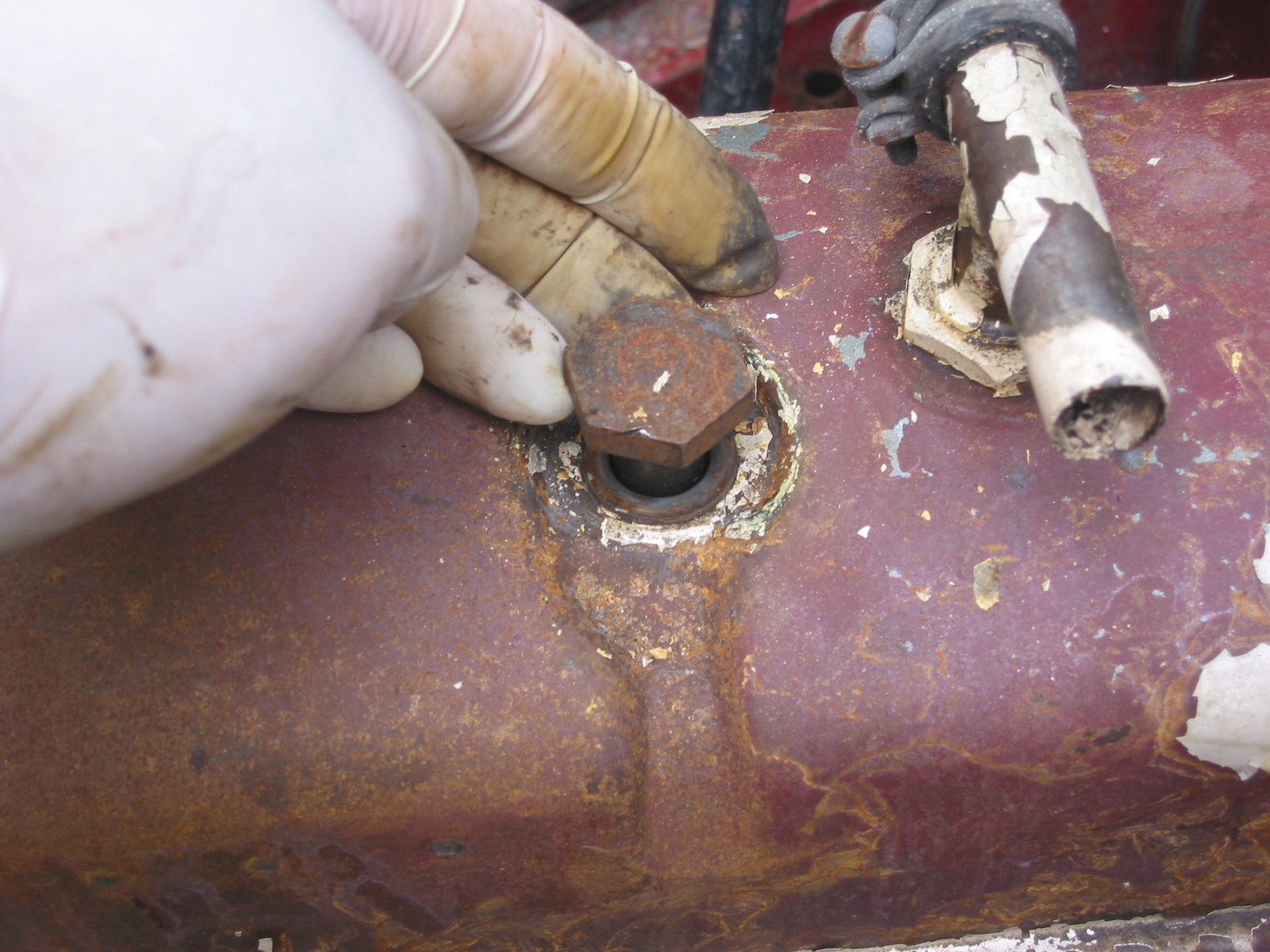
Gearbox mounts – Removed 4 bolts securing the gearbox mounts and 4 bolts and nuts from the Propshaft at the gearbox union. The bolts on the gearbox side cannot be removed without removing shaft nut. There were also 2 nuts of the same size to remove on the underside of the chassis. Finally, the nut and securing pin on the gearbox stabilizer must be loosened and removed to free the gearbox.
Propshaft Removal
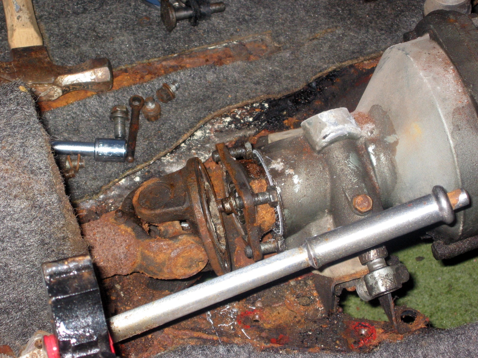
Clutch slave cylinder – Detached the cylinder from the bell housing by removing 2 bolts. Must also release the clutch operating lever by removing the cotter pin from the clevis pin.
Disconnected the wire clamp on the bell housing and unclipped the wire to the gearbox switch for the overdrive.
Overdrive Wiring Clip

Overdrive Wiring
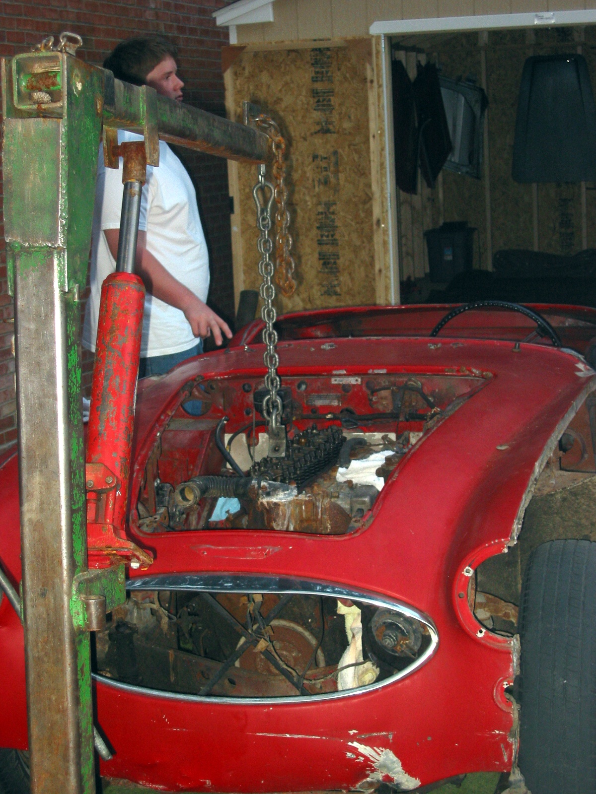
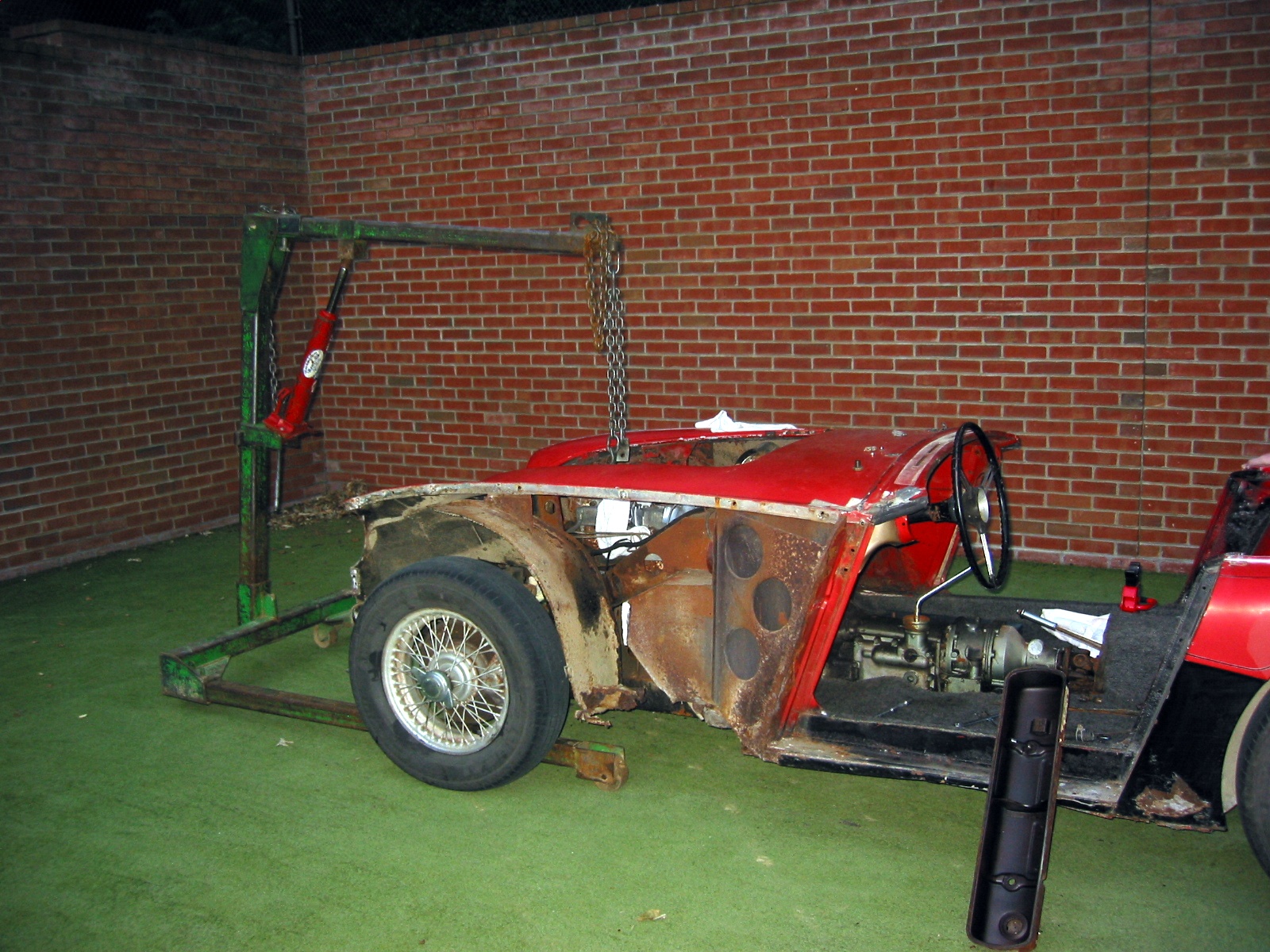
Engine Hoist – We then thought we were ready to connect the hoist and remove the engine and gearbox as one unit. If we were doing this again, we would have waited until the shroud was removed to avoid any damage. It would have also made it easier to swing out the entire unit had we jacked up the car a bit first. That would have given the gearbox more room to swing vertically. Providing enough lift height on the hoist is a bit of a problem given the length of the combined engine and gearbox and the angle needed to successfully remove the unit.
We also decided that while it isn’t theoretically necessary, it would be easier to pull the engine if the brake reservoir were removed. So we gave up due to darkness and gently reset the engine in the bay.
Helper Scott
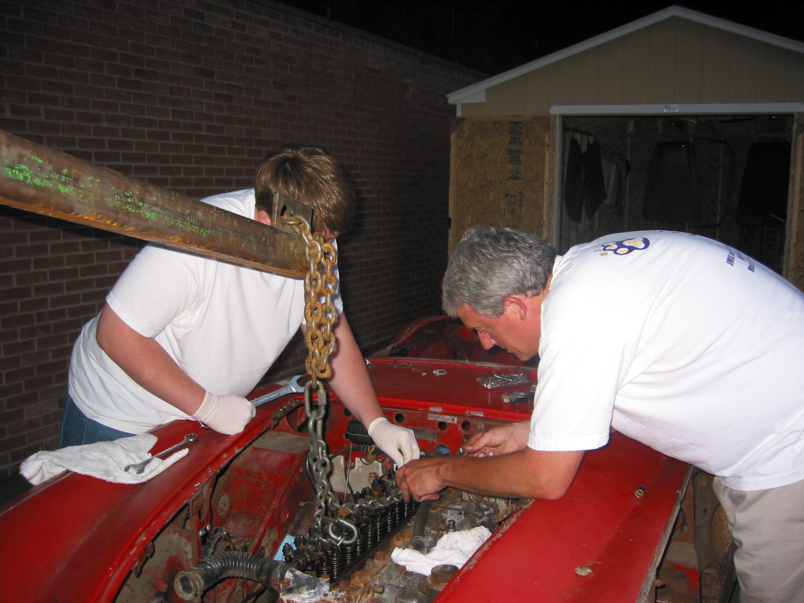
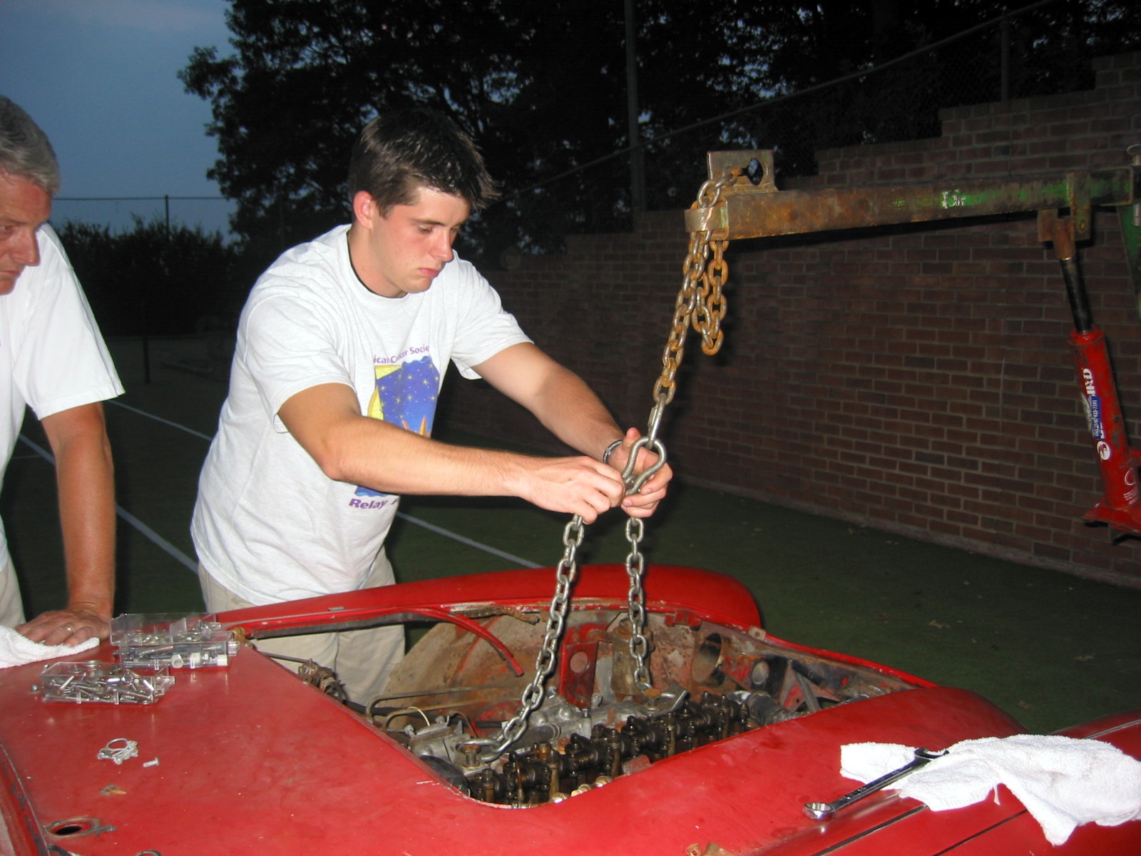
Securing the Hoist Chain
Helper John
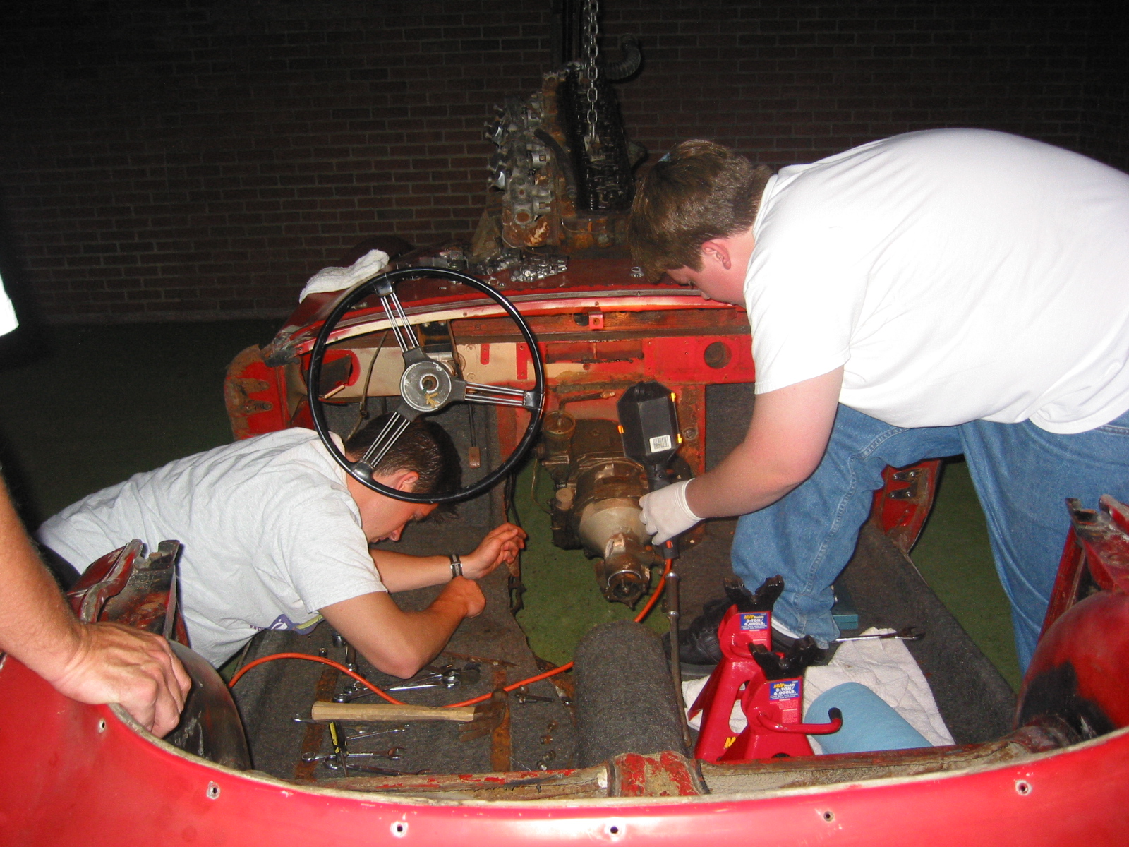
Freeing the Gearbox
Progress!
Resting for the Night!
July 4, 2000
Engine Removal, cont’d
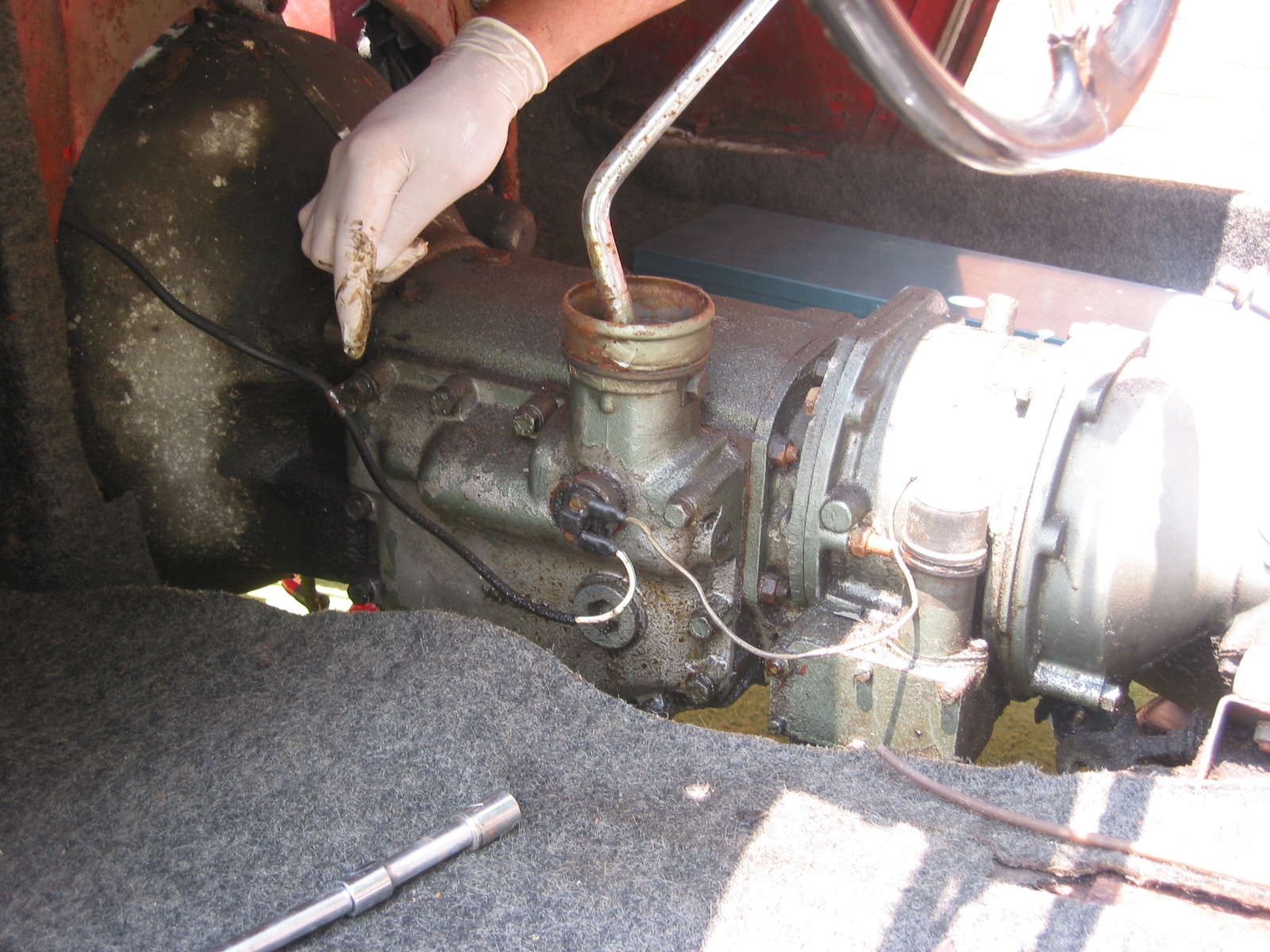
Brake fluid reservoir – Removed the container by loosening one nut securing the bracket, and then loosening the two brass brake line nuts to the container. Note that there are also nuts on the bottom of the canister.

Brake/Clutch Fluid Reservoir
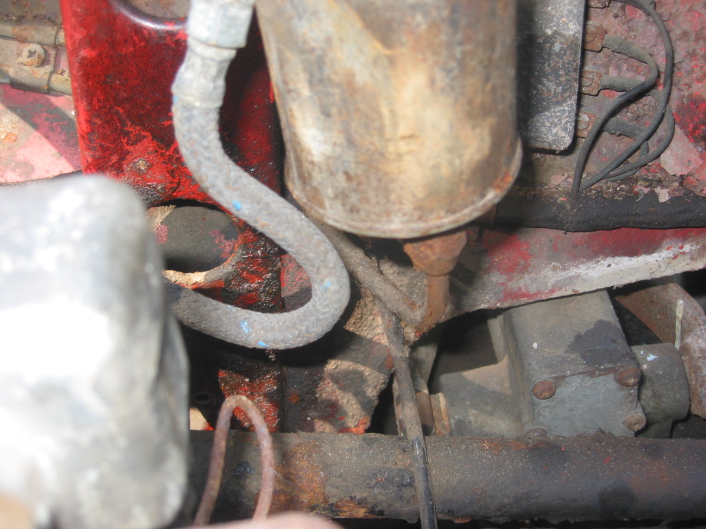
Brake/Clutch Fluid Pipes to Reservoir
Hydraulic lines – Removed the hydraulic lines from the master cylinders to the reservoir canister. Note double clasp or clip on fender secured by a nut and bolt on outside of fender well. The longest pipe is the brake and is connected closest to the front of the car. Shorter pipe is the clutch line.
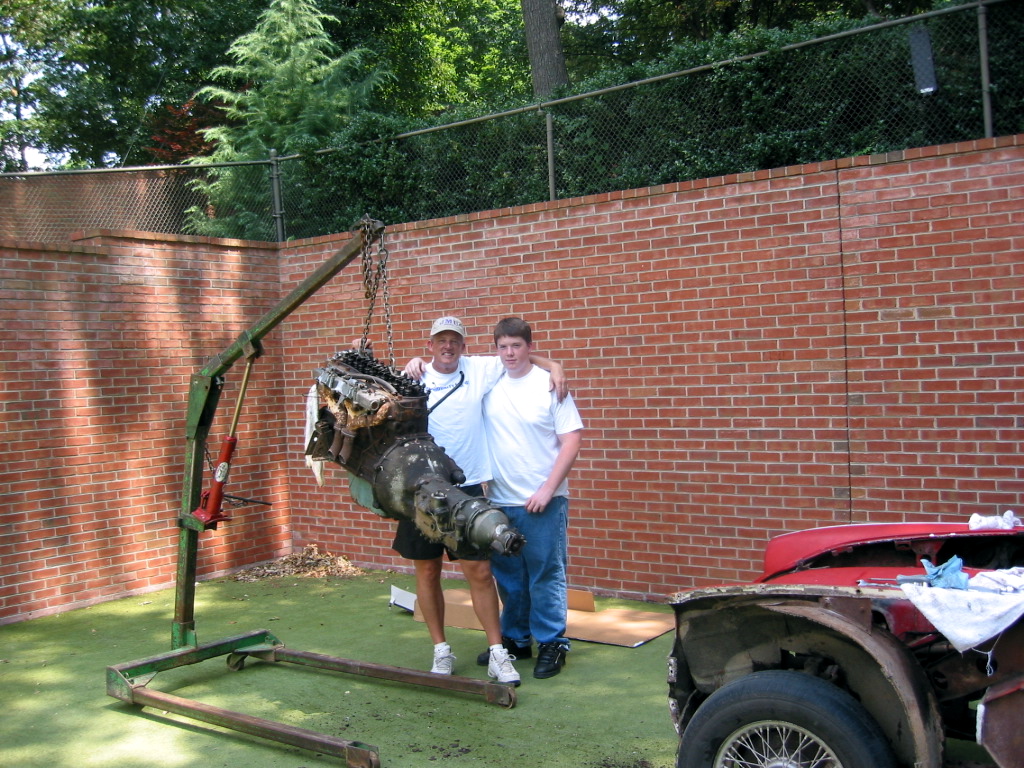
Attempted to remove the engine with the lift again. This time with better light, a less crowded space and with the lift chain adjusted we easily removed the engine and transmission.
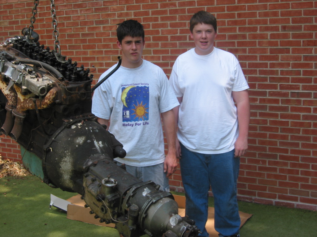
The Helpers Got it Done!
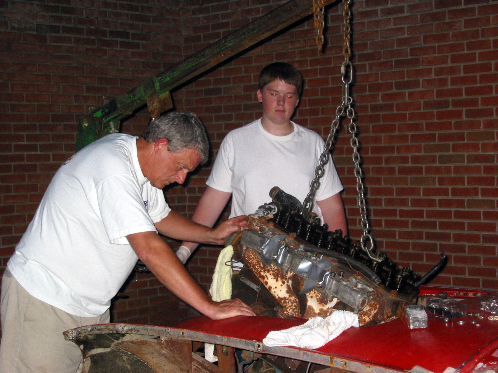
Lin, Scott and the Beast
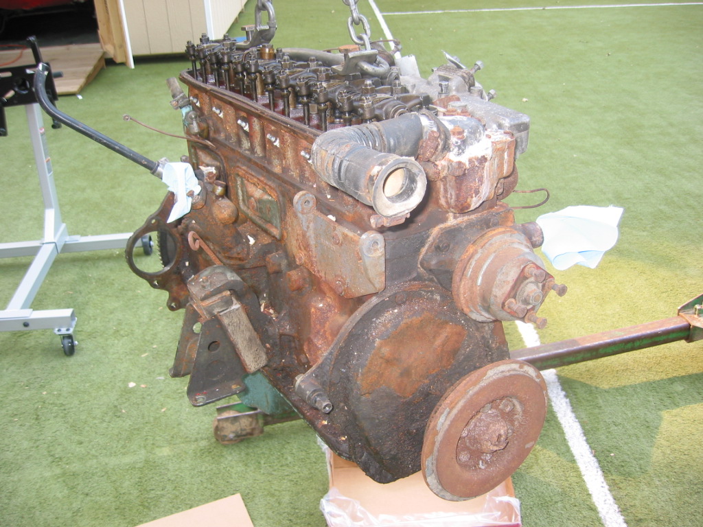
Free at Last with Gearbox Removed
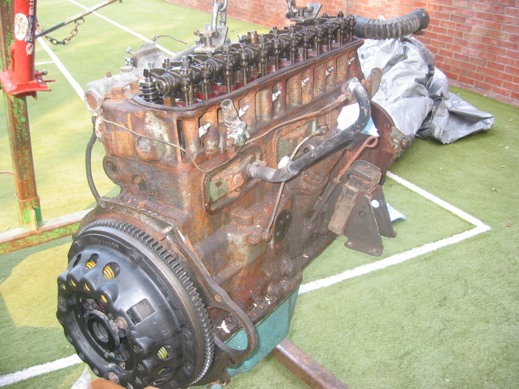
Clutch Assembly and Ready For the Engine Stand
To mount the engine on the stand it was necessary to remove the gearbox from the engine. The bell housing was secured with 9 3/8” x 24 bolts including two that mount the starter. The bolt on the top right secures to the engine block without a nut. All other bolts have nuts. After removing the transmission we then had to remove the clutch. You must gradually slacken the cover screws a turn at a time until the spring pressure is relieved.
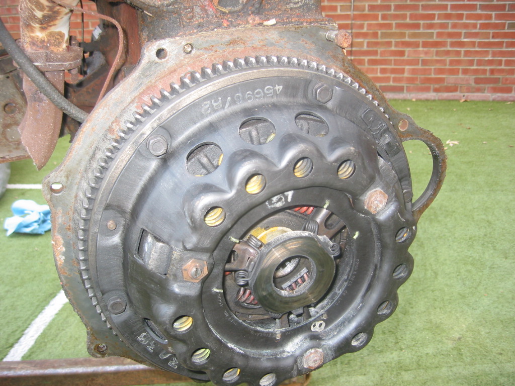
Clutch Assembly 1

Clutch Assembly 2
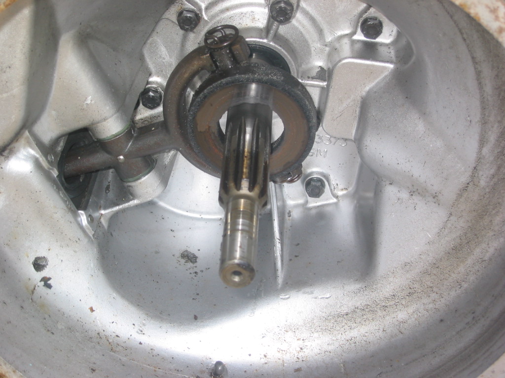
After the clutch assembly was removed, the flywheel was exposed. Four nuts with the lock washer straps were loosened. The crankshaft pulley must be held on the front of the engine to prevent the shaft from turning.
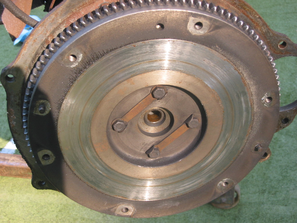
Exposed Flywheel
Clutch Fork
We were then able to transfer the engine from the lift to the engine stand.
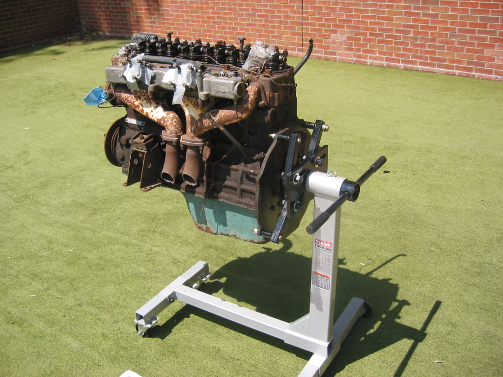
On the Engine Stand

Engine Stand Mounting
July 22, 2002
Wings
The Front Wing – Removed 3 bolts joining the front shroud and the front wing below the headlight. These are slightly shorter than those used to secure the top of the shroud and the wing together. They are tightened to spring-clip type nuts. Removed the headlight and sidelight. The sidelight is fastened with three small screws and nuts on the reverse side. Two pieces of plastic piping are found above and below the sidelight. Four brass nuts accessible beneath the wing hold the headlight bucket in place. Seven bolts fastened the shroud to the wing along the top edge. Three bolts and nuts secure the wing to the frame along the bottom edge. Seven small self tapping screws fasten the wing in the door jamb to the hinge pillar.
The Rear Wing – Removed three bolts inside the interior and three inside the boot to remove the rear wing. The bolt located closest to the rear of the car, but still in the interior has a regular nut rather than a clip spring nut which must be held with a wrench when removing. There is also a screw near the door under the aluminum trim that fastened into a steel plate. At the bottom of the rear wing there are two bolts and nuts securing the wing to the frame and a vertical drive sheet metal screw. Finally, eight cross-head screws with nuts fix the wing to the door shut pillar and they must be removed.