Clutch and Gearbox
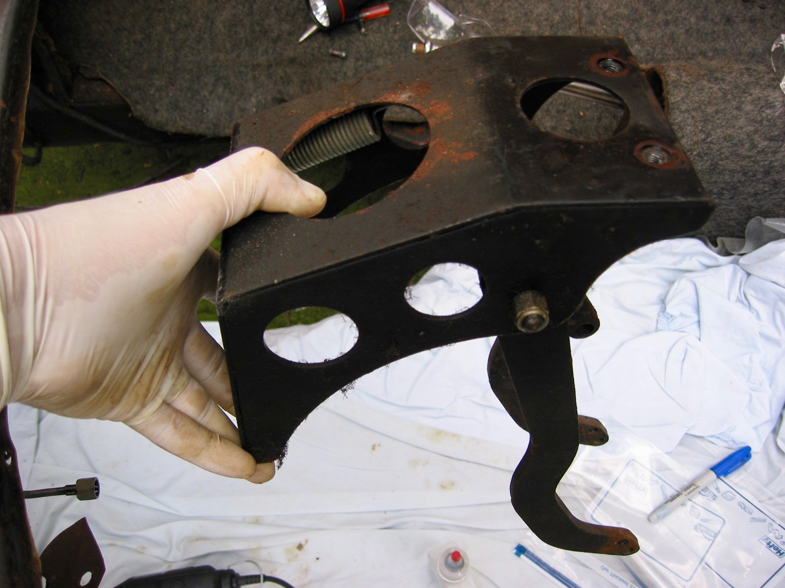
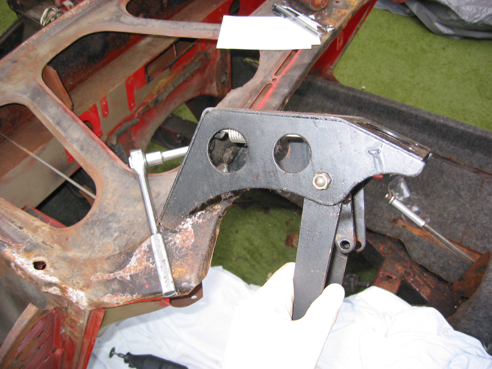
Clutch Master Cylinder
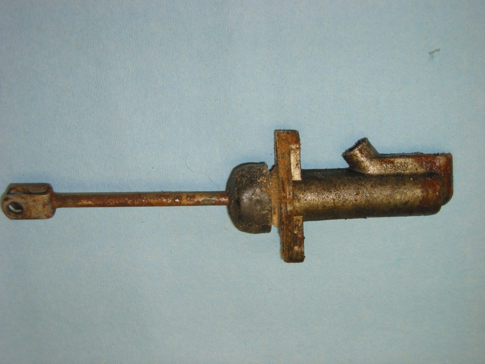
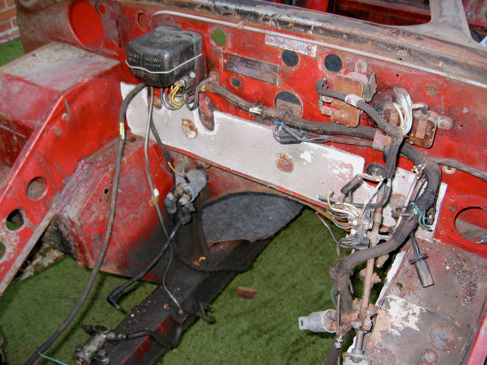
I will replace the master and reservoir seen here with a new unit.
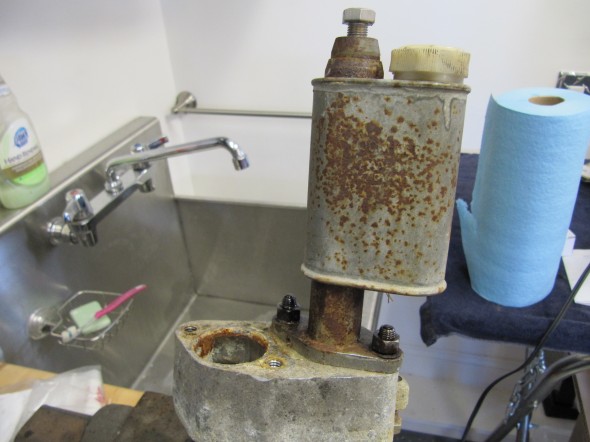
Clutch Master/Reservoir
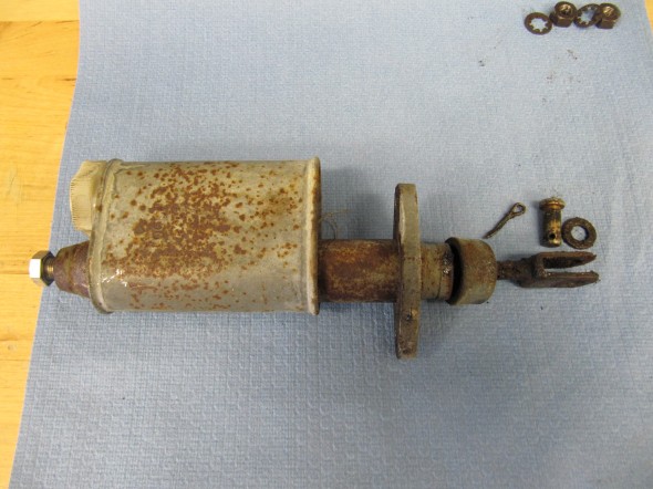
Clutch Master/Reservoir
Since the clutch master and the brake master share the same housing and pedal box, information about those components is addressed under the brake servo and hydraulics post at this link: https://valvechatter.com/?cat=615
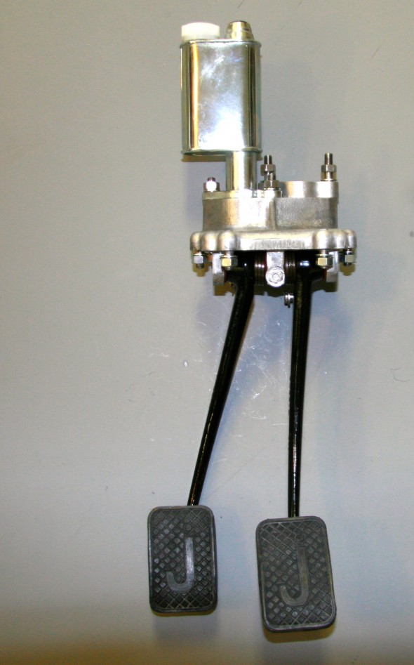
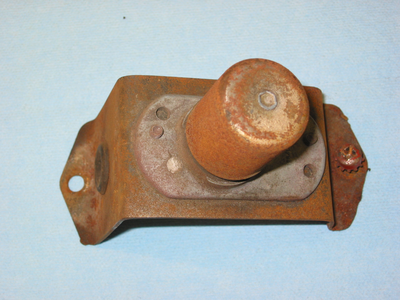
Clutch Master Cylinder, Reservoir Mounted to Housing with new Pedal Rubber
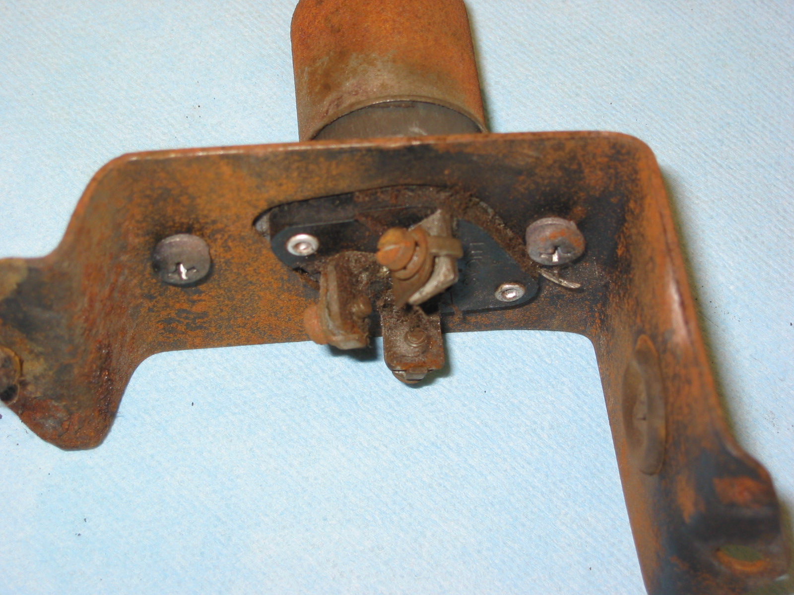
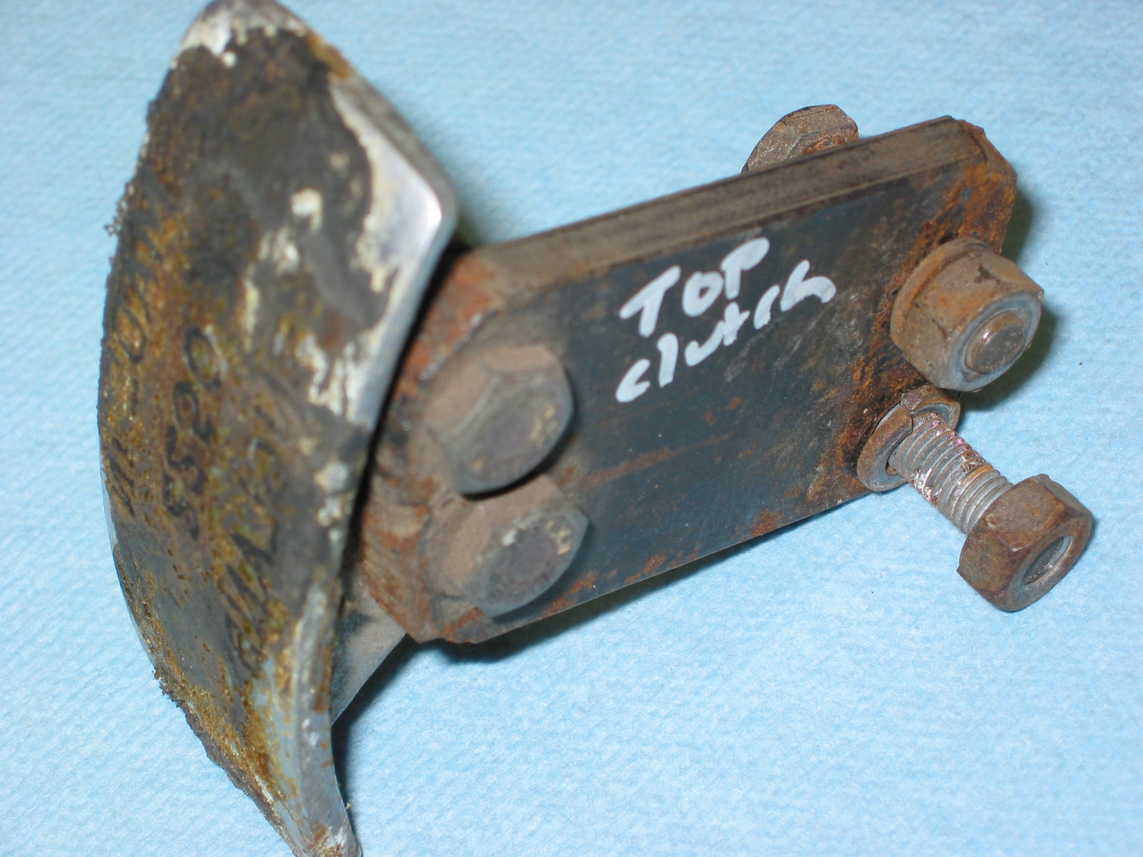
Bracket for Flexible Clutch Hose at Rear of Cylinder Head
This little bracket is in a conspicuous location and called for re-chroming.
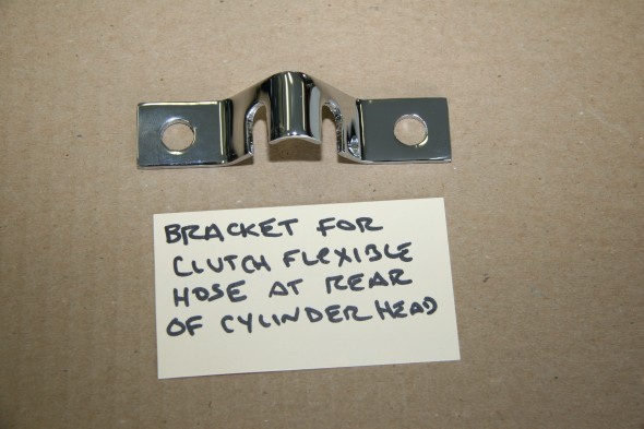
Clutch Flexible Hose Bracket at Rear of Cylinder Head
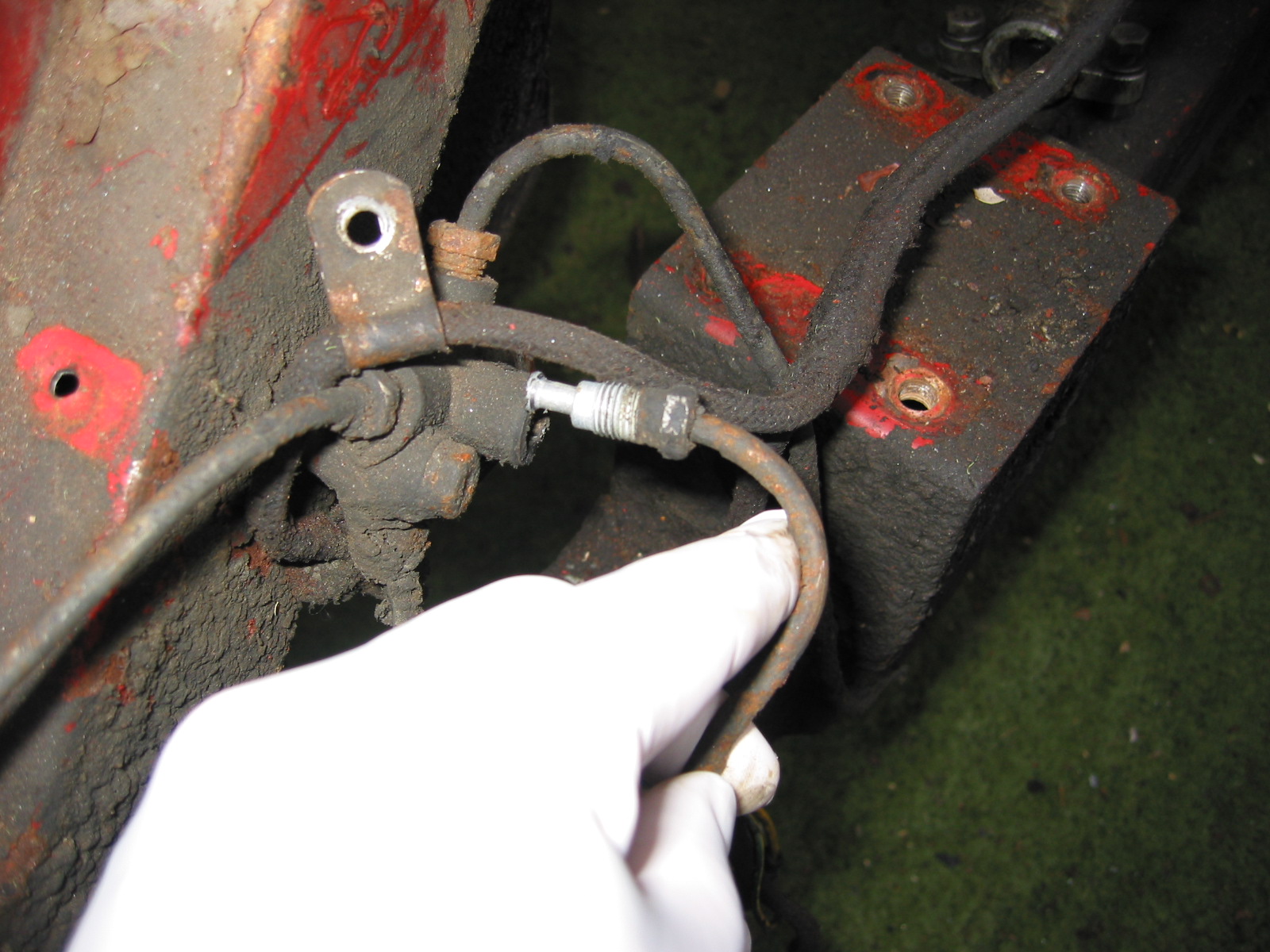
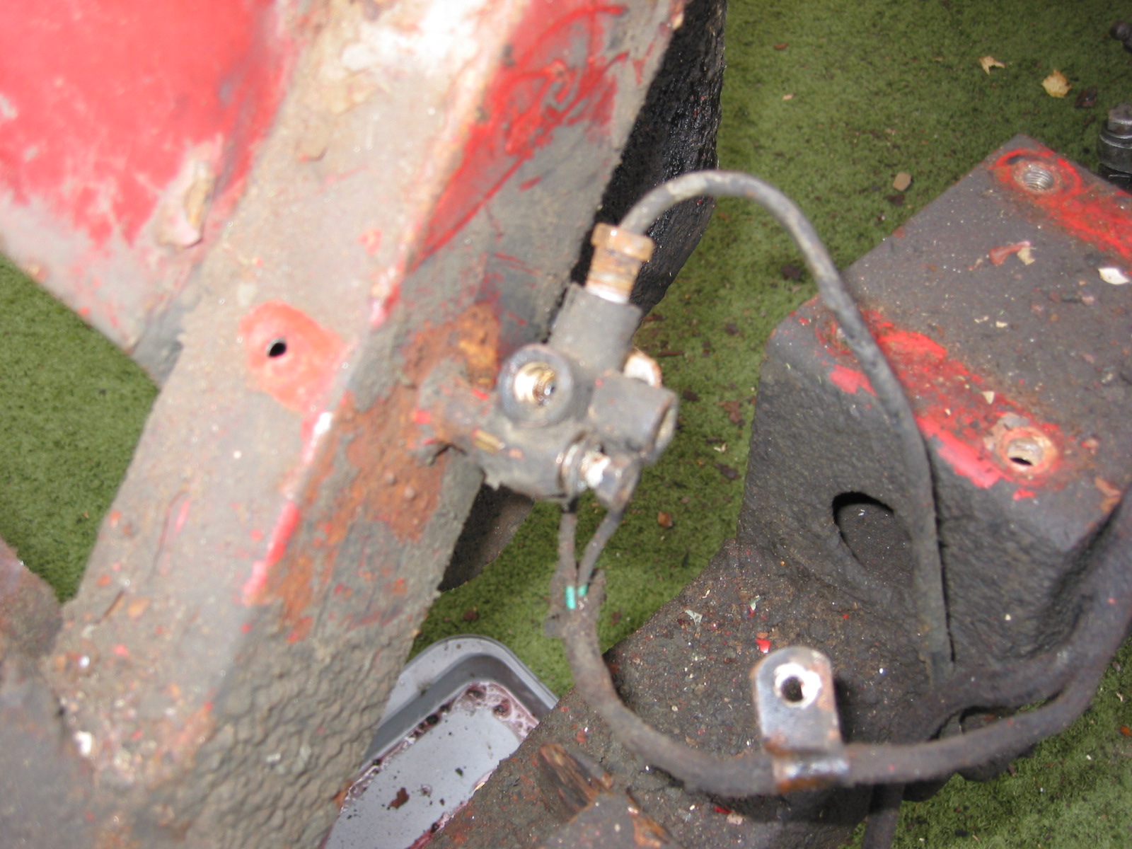
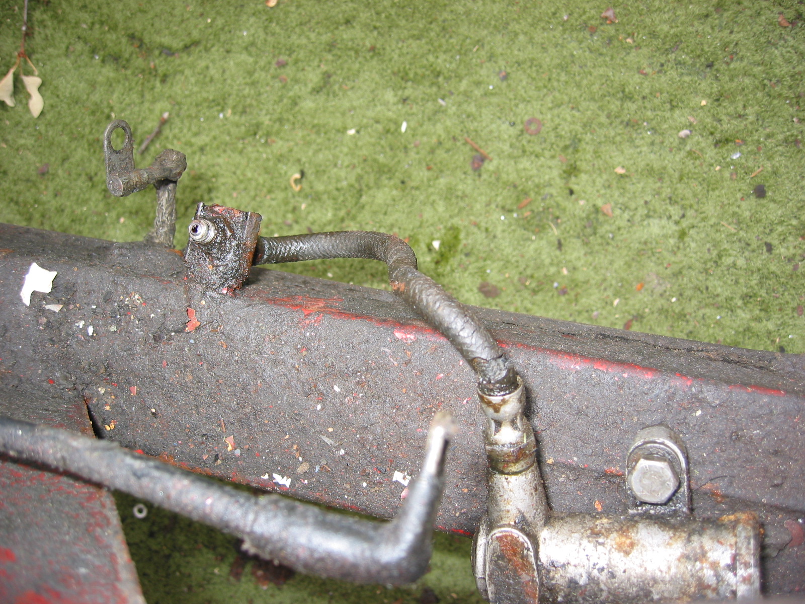
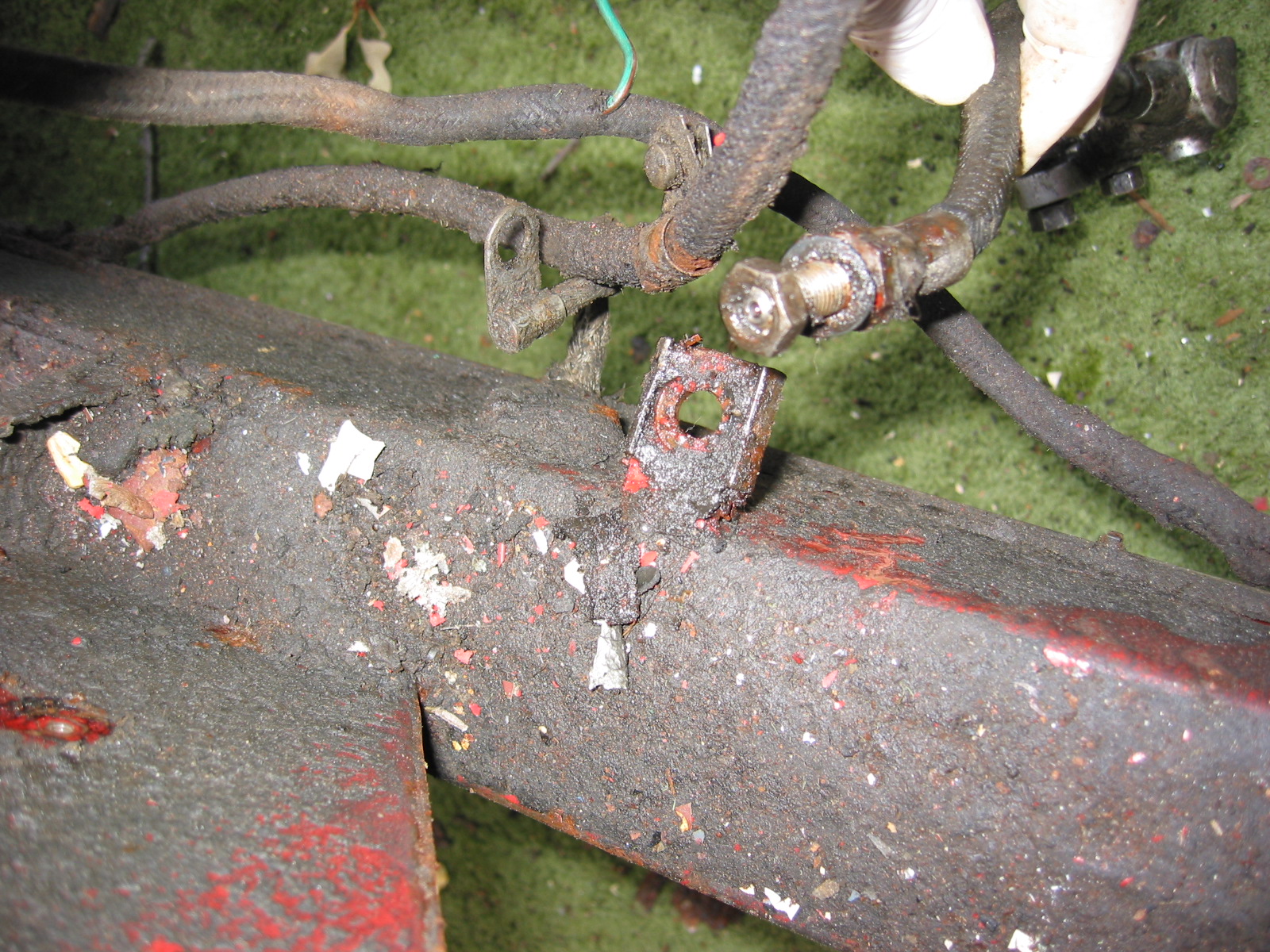
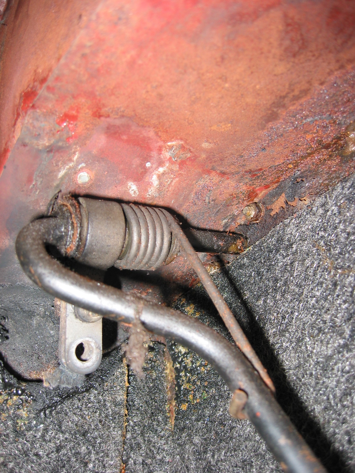
Slave Cylinder Hydraulic Pipe
A hard line attaches to the flexible stainless steel hose at the cylinder head bracket (shown above) and connects to the slave cylinder. It is held securely by one clip attached to the bell housing. The new line was sourced from Classic Tube along with the pre-bent brake lines.

Slave Cylinder Hydraulic Line
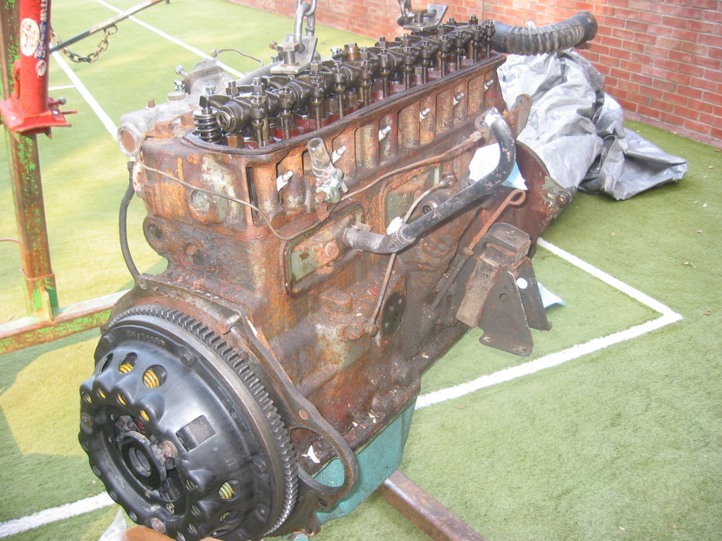
Clutch
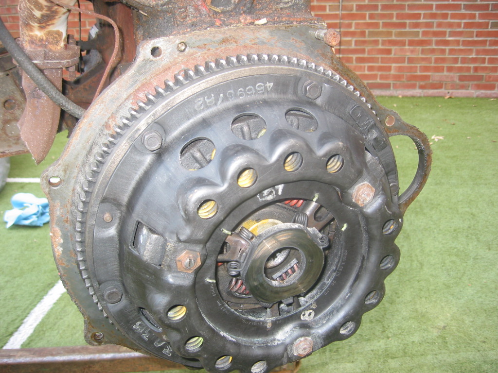
The 1964 MK2 used a spring-loaded, hydraulically-operated, driven plate assembly with cover and a graphite release bearing. Later models switched to a diaphragm clutch. While the diaphragm cultch is probably easier to operate, I decided to stick with the original type in my restoration. The entire clutch assembly was purchased from SNG Barratt and installed by my engine builder, Mike Gassman, from Gassman Automotive. The unit was balanced with the engine for smoother running.
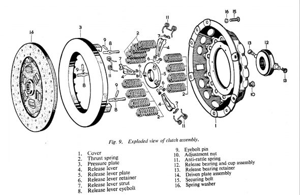
MK2 Clutch Diagram
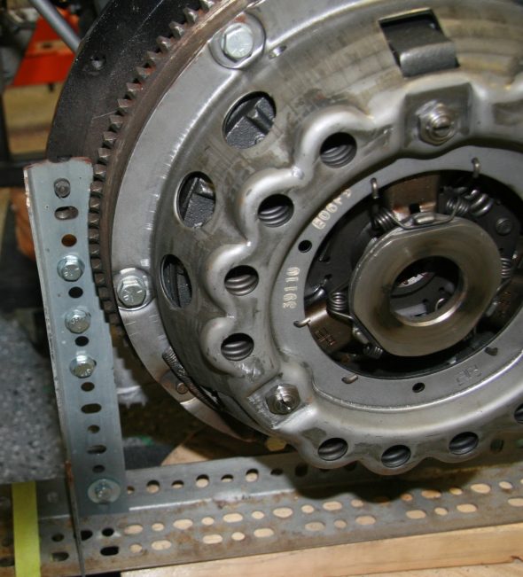
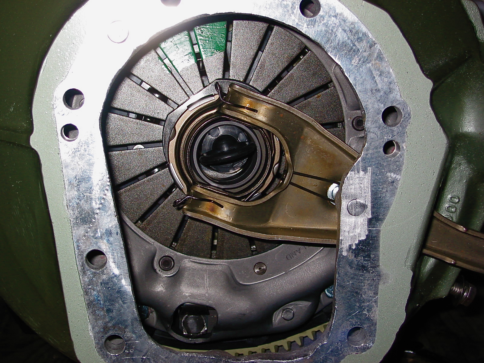
MK2 Clutch Assembly
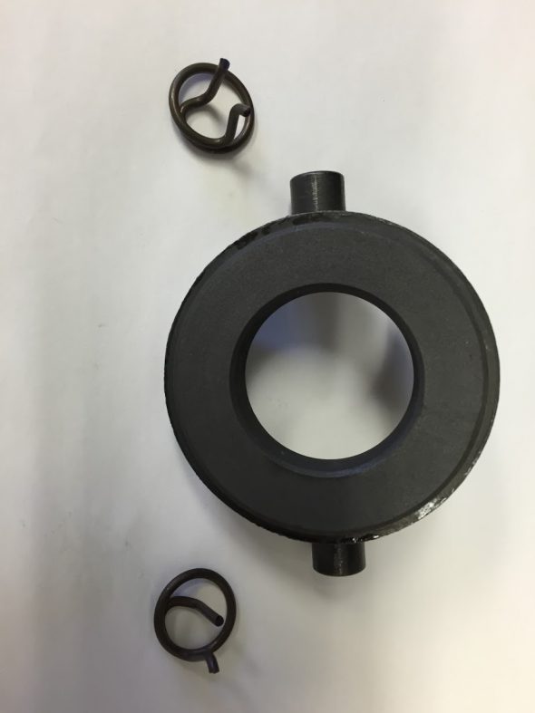
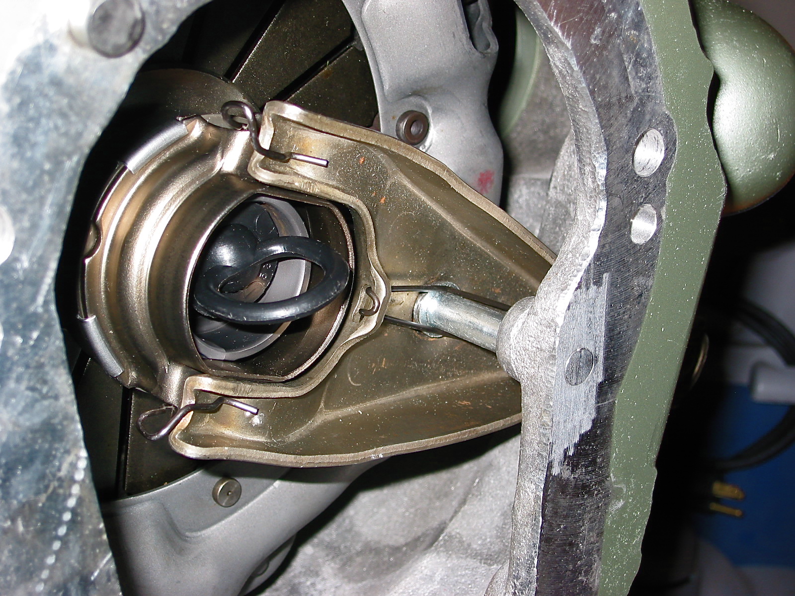
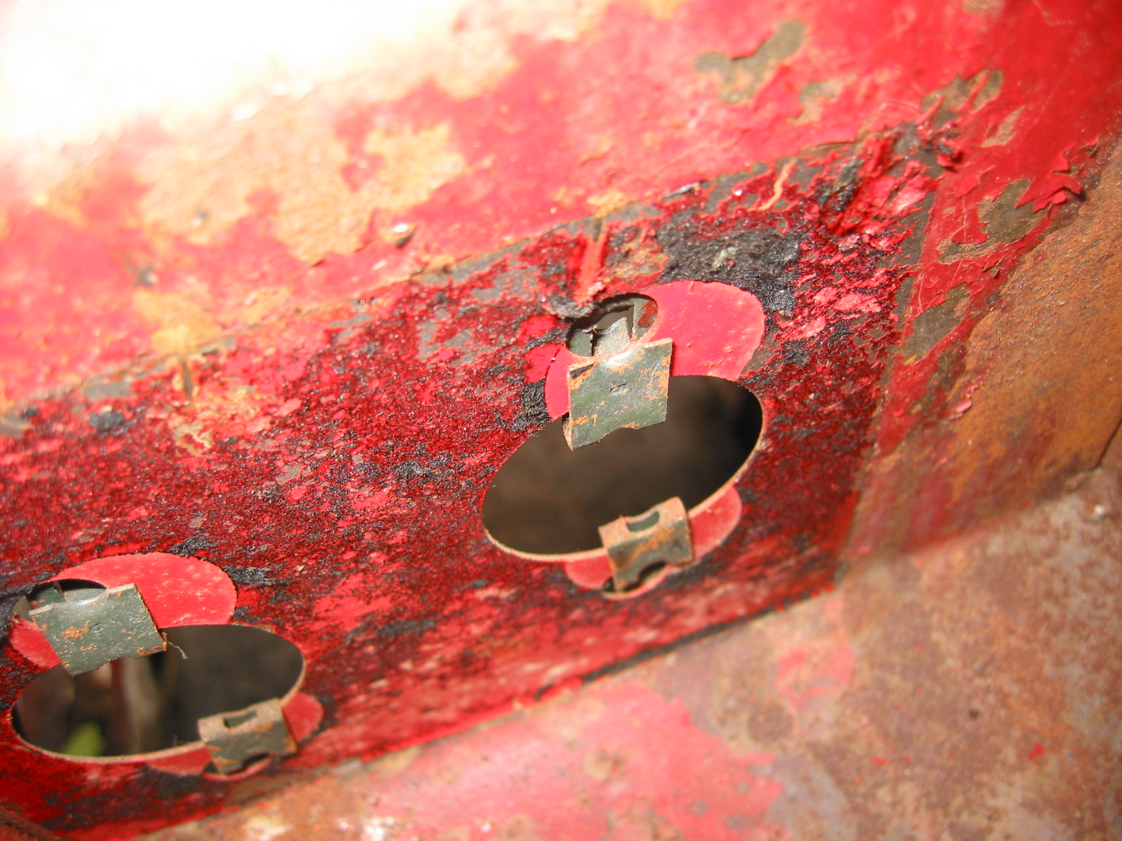
Release Bearing and Clips
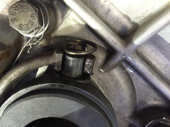
Release Bearing Mounting Clips
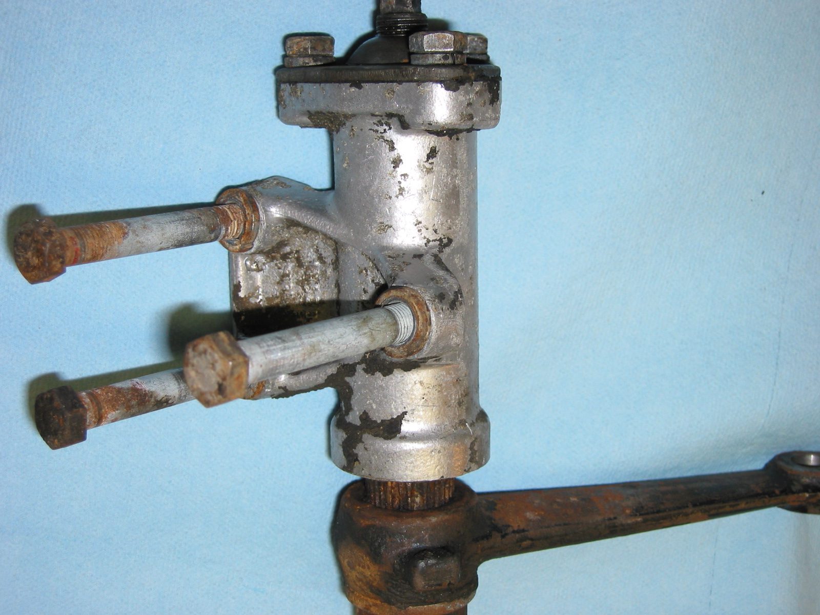
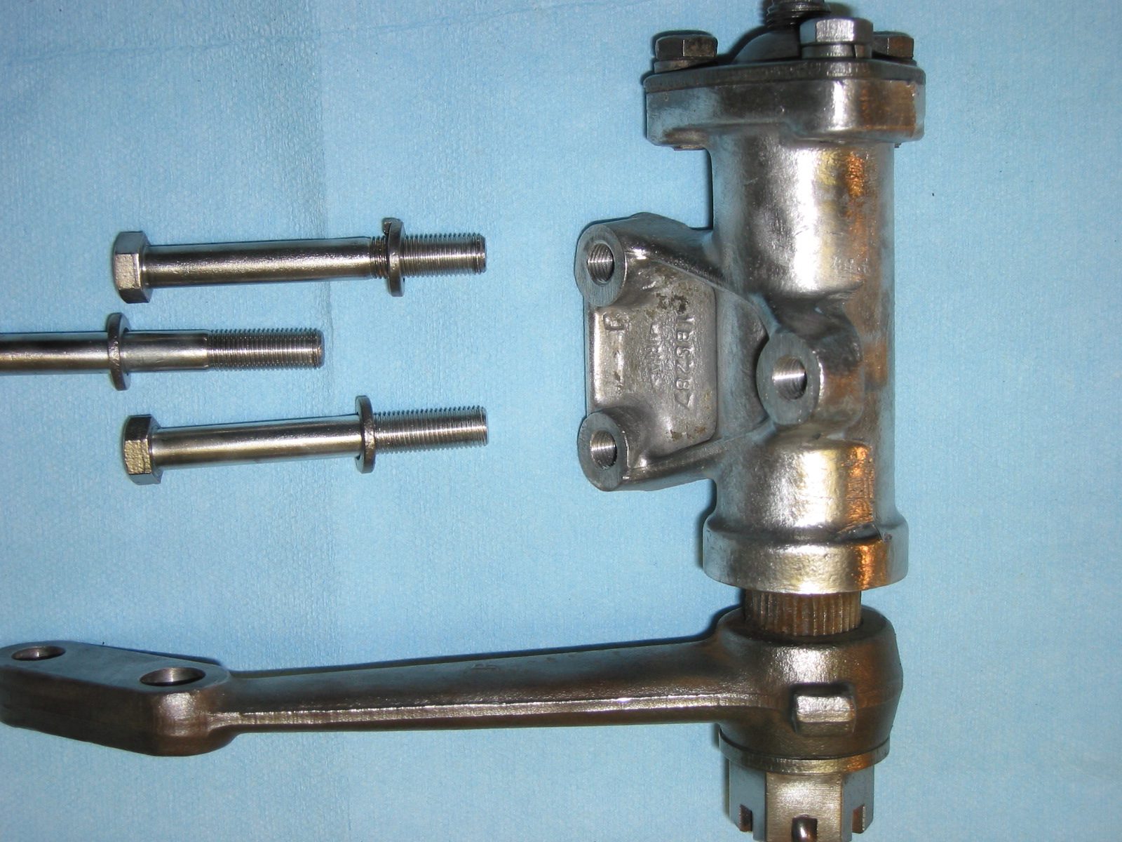
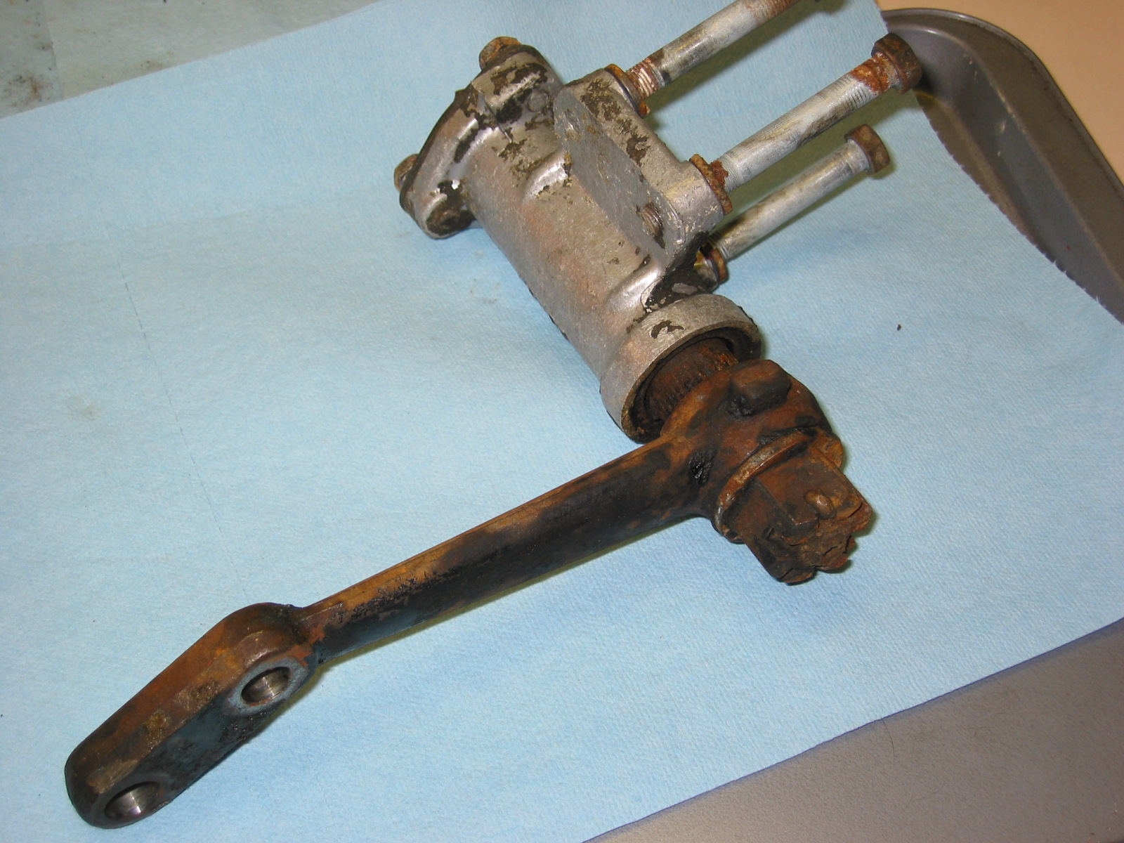
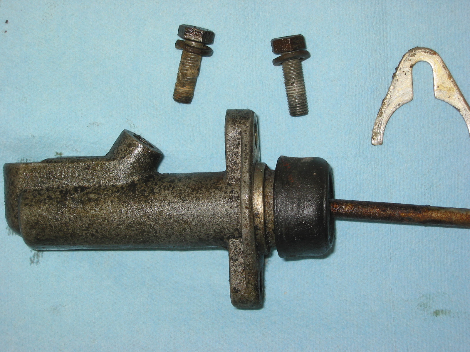
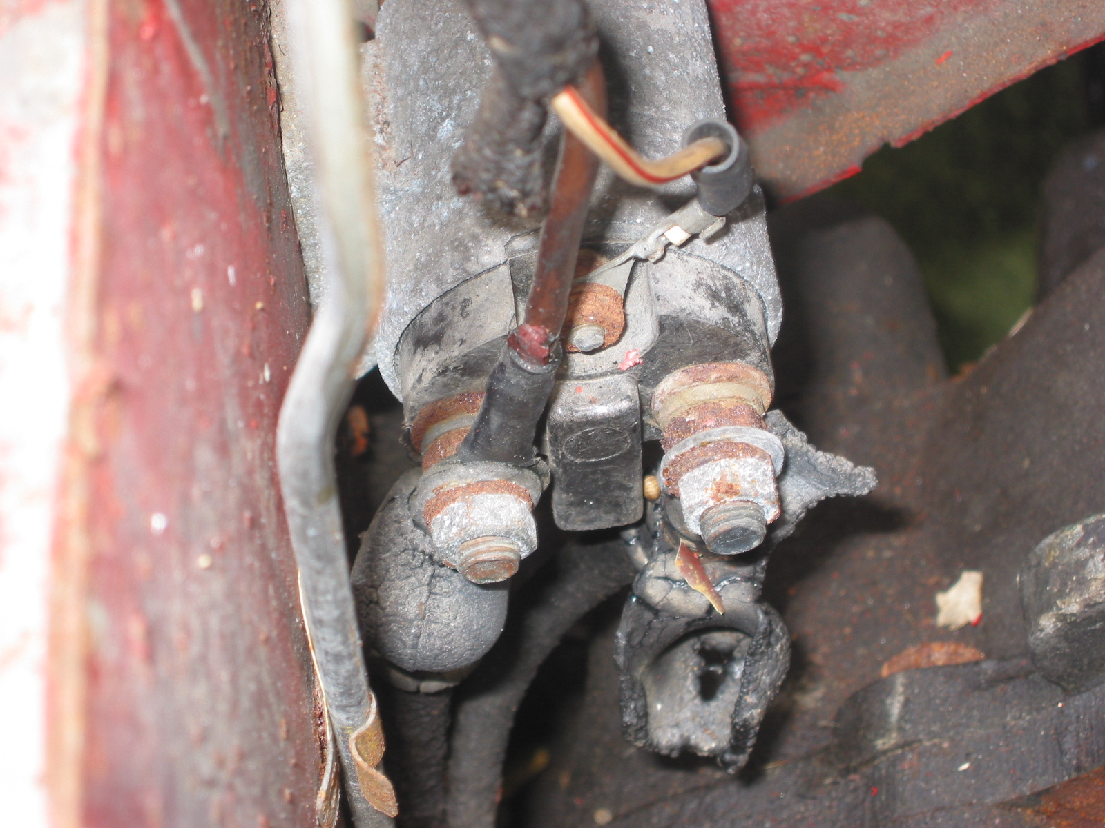
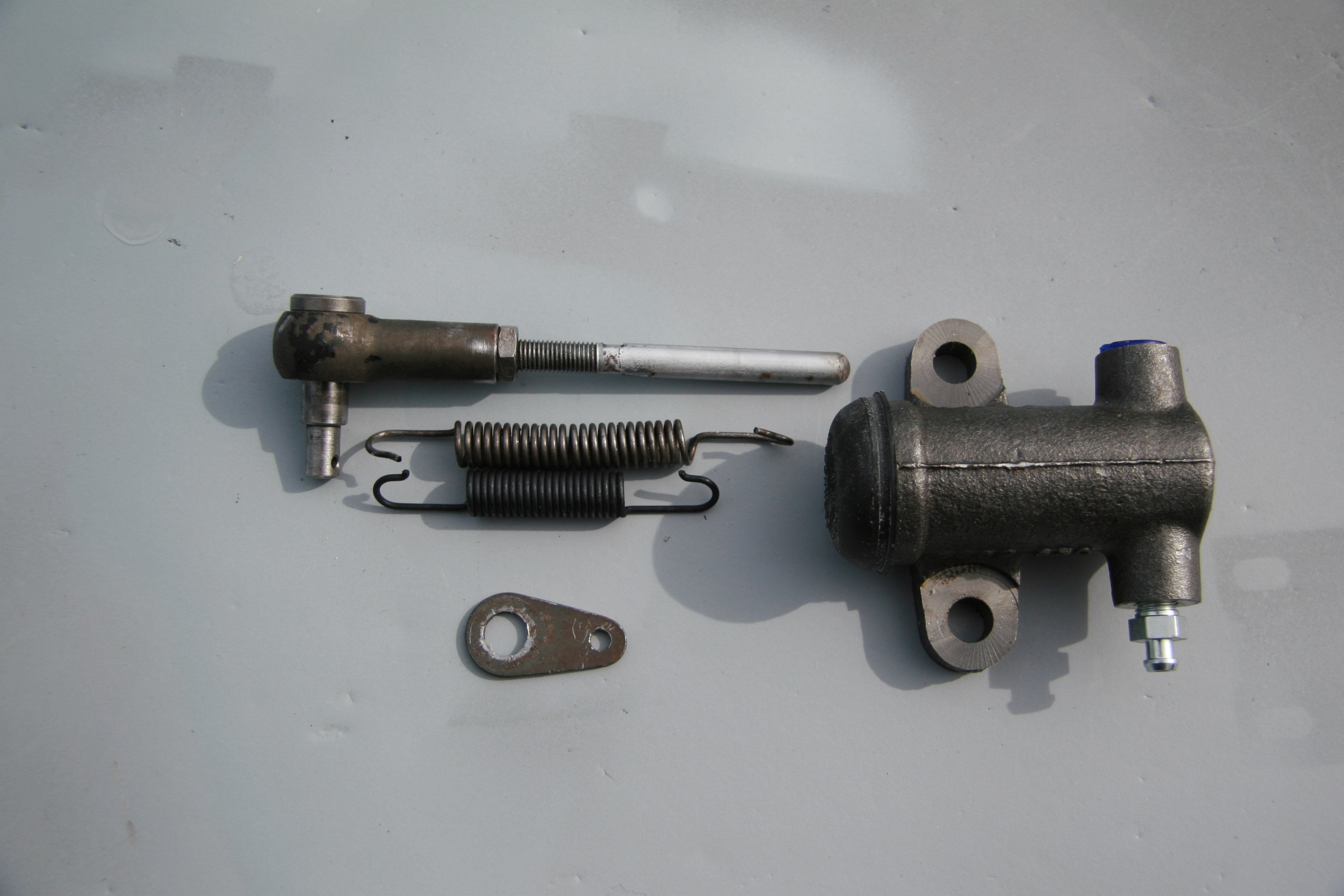
Clutch Slave Cylinder
Fortunately, the replacement slave cylinder sourced from SNG Barratt is exactly the same as the original. the rubber boot is somewhat different, but otherwise identical. The new return spring is; however, shorter than the spring currently on the car. Not sure if it is a different spring or if the original is stretched. In any case, I shall try the new one (which did have the proper Jaguar part number) and see how everything functions.
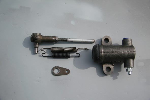
Slave Cylinder
Assembly
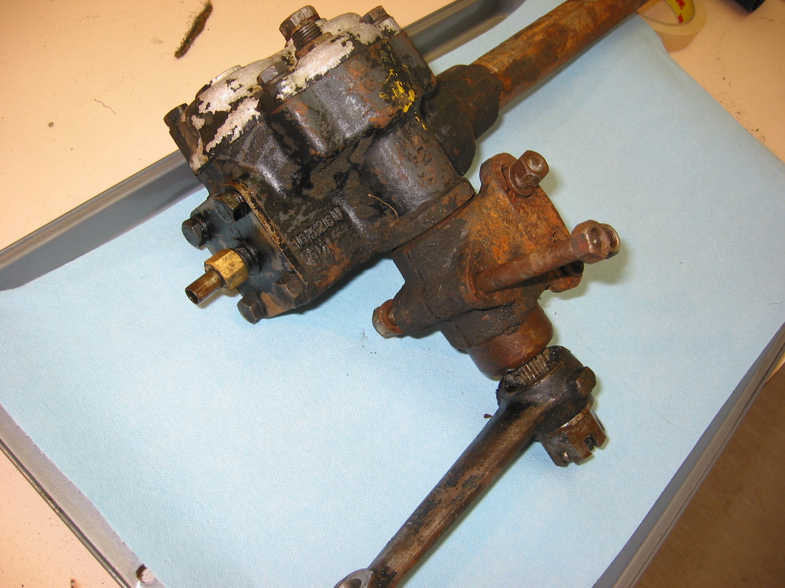
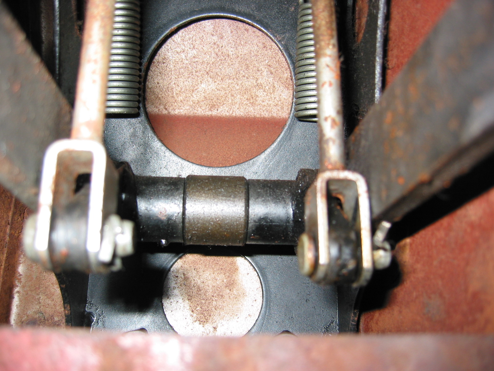
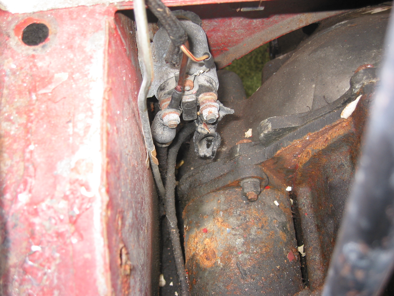
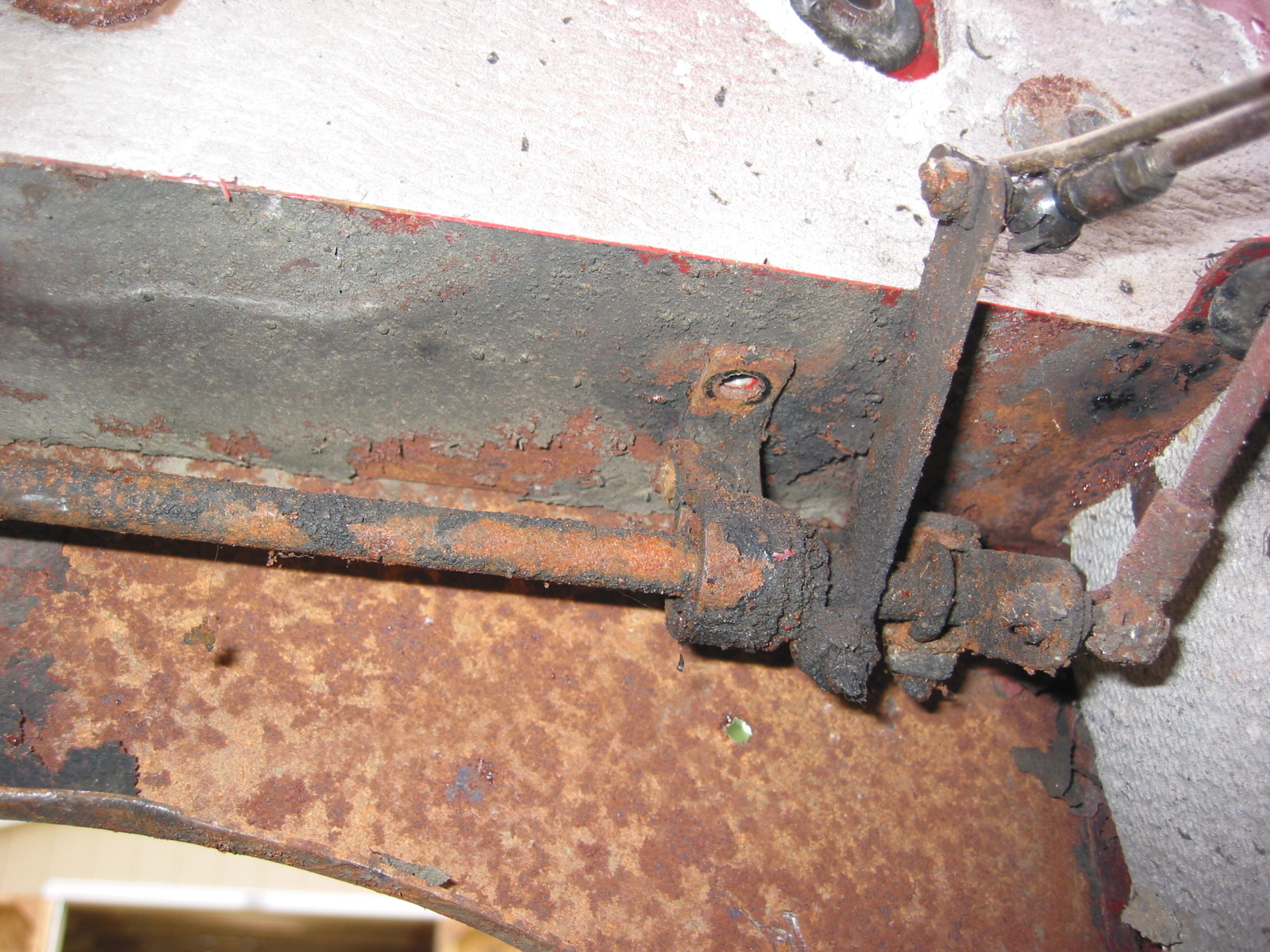
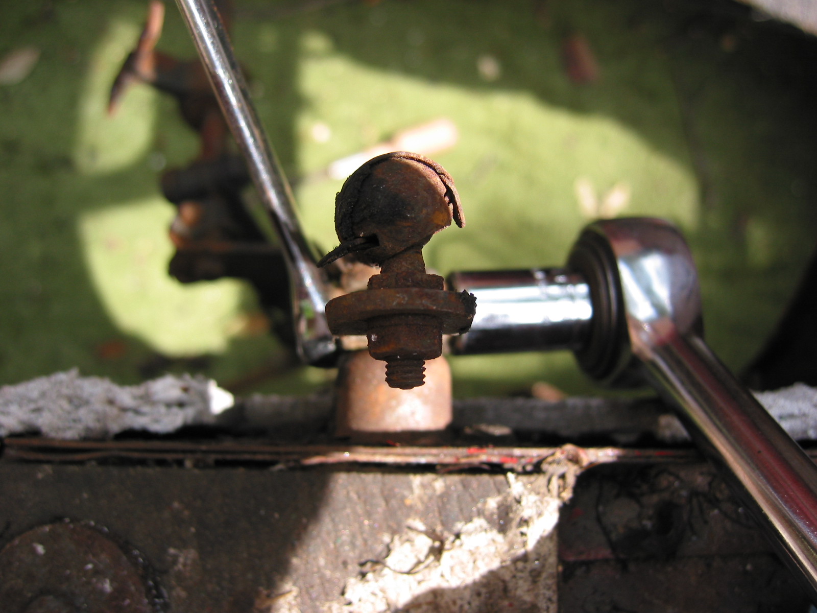
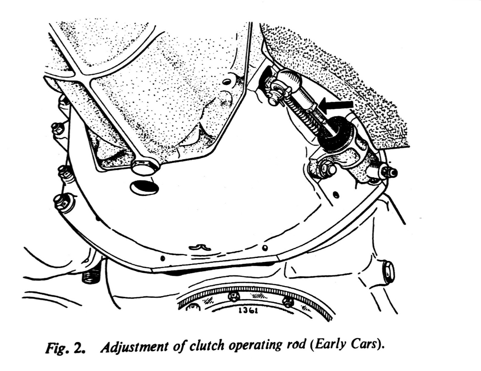
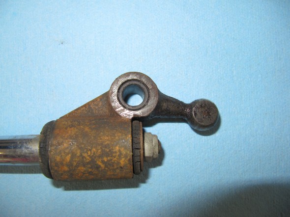
The Jaguar Service Manual states that “there should be 3/4″ free travel or unloaded movement at the pedal pad before feeling the resistance of the clutch thrust springs. The free travel is most easily felt by depressing the pedal pad by hand until a marked resistance is felt. Adjustment is effected by slackening the lock nut and turning the operating rod between the slave cylinder and the clutch withdrawal lever. Screwing the rod into the knuckle joint will increase the pedal travel; screwing the rod out will decrease the free travel.”

MK2 Clutch Slave Cylinder Adjustment
Gearbox and Overdrive The gearbox is a four-speed type with synchromesh on the second, third, and top gears. The overdrive is a Laycock de Normanville. First and reverse gears are 12.731:1, Second is 7.012:1, Third is 4.836:1, and fourth is 3.77:1; with the overdrive engaged the top gear ratio is 2.933:1. A synchronized fiord gear was added later in production.
According to Nigel Thorleys excellent book – Original MK1/MK 2 the all synchro box was fitted in Sept 1965 from chassis no 119200 – 2.4 RHD 127822 – 2.4 LHD 169341 – 3.4 RHD 180188 – 3.8 LHD
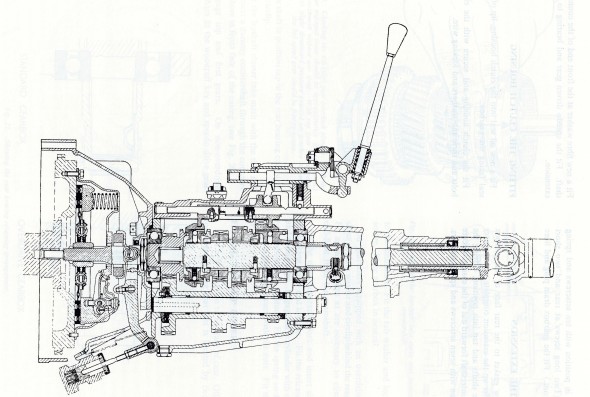
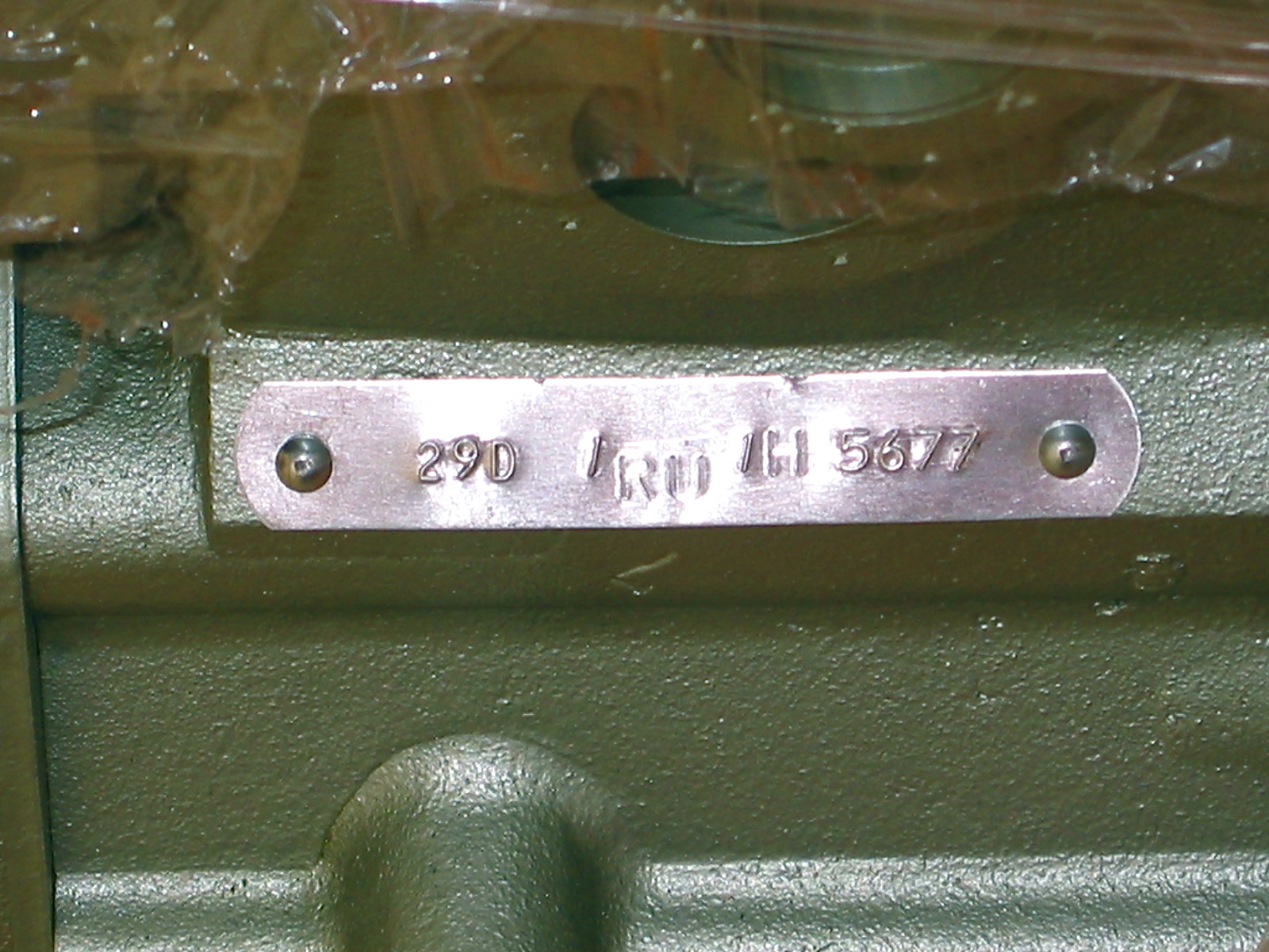
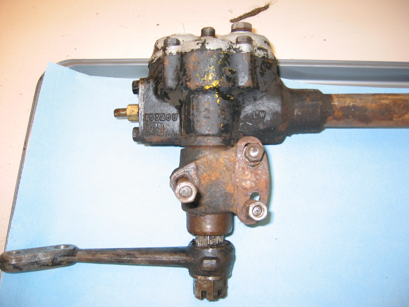
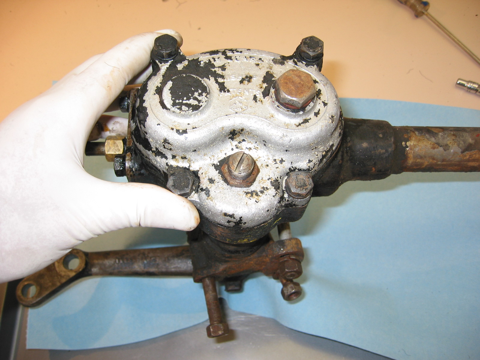
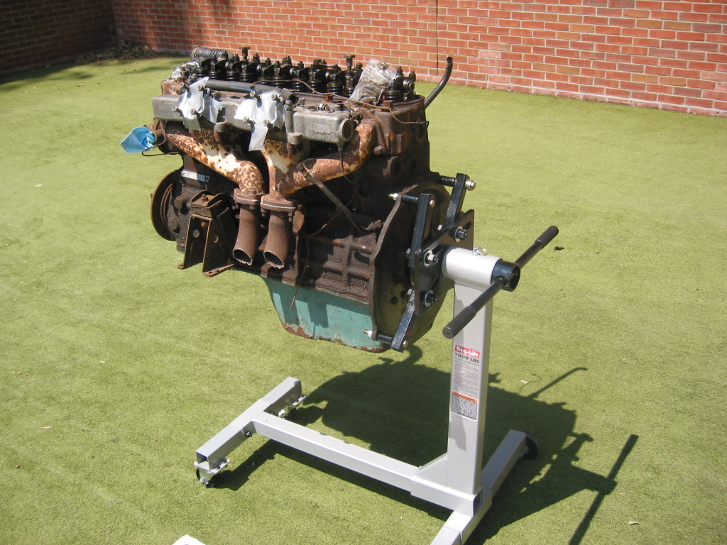
MK2 Gearbox
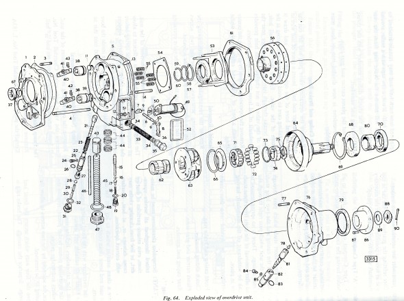
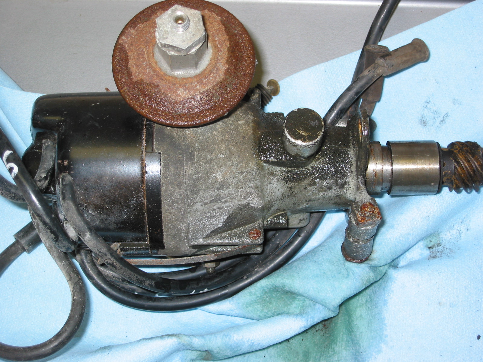
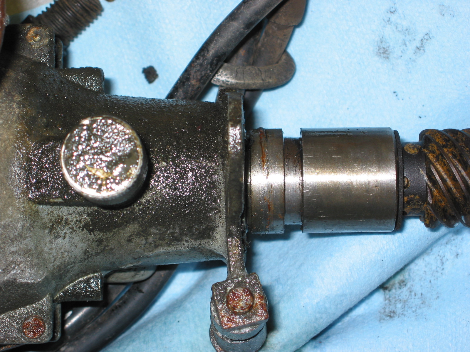
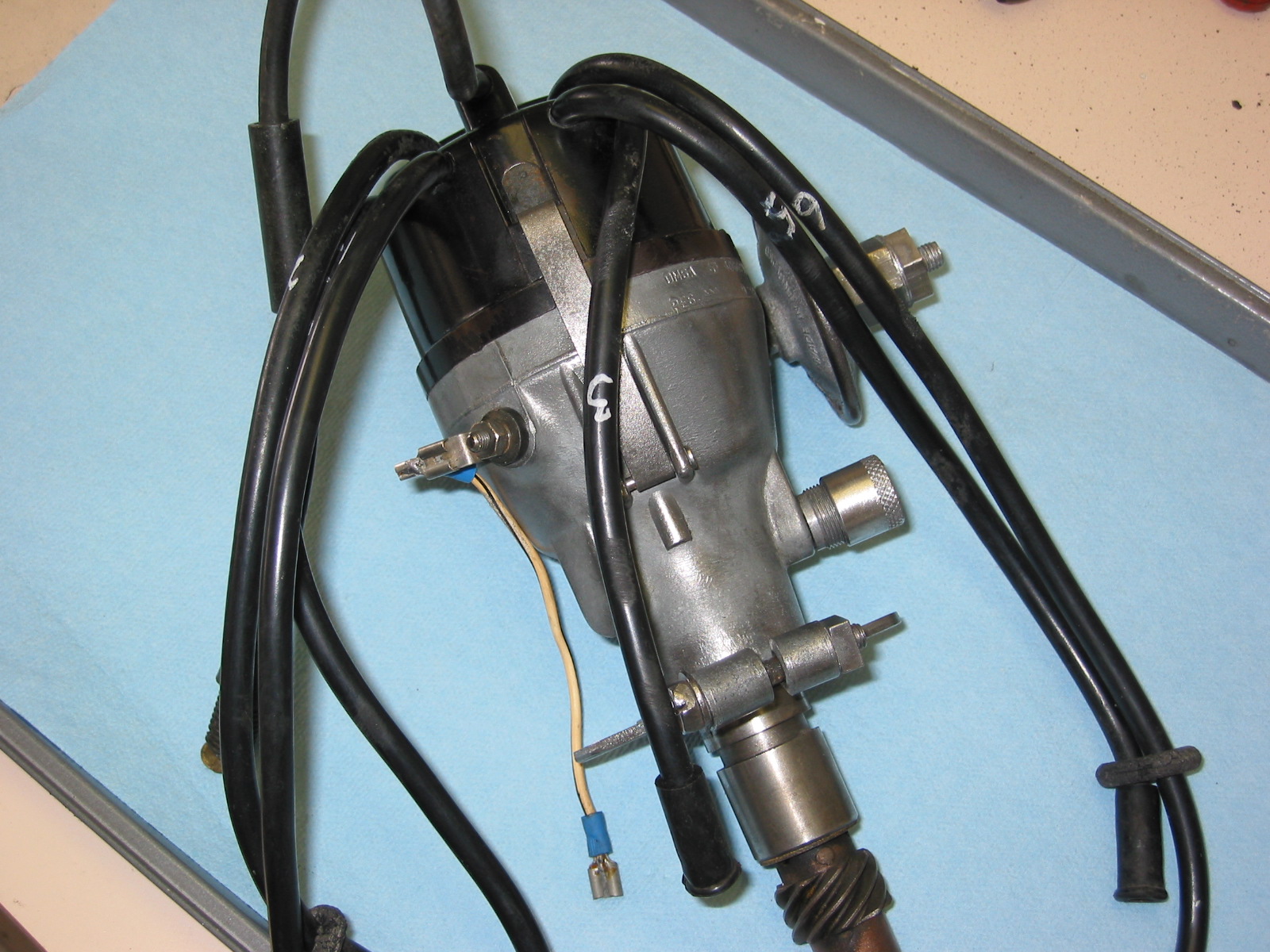
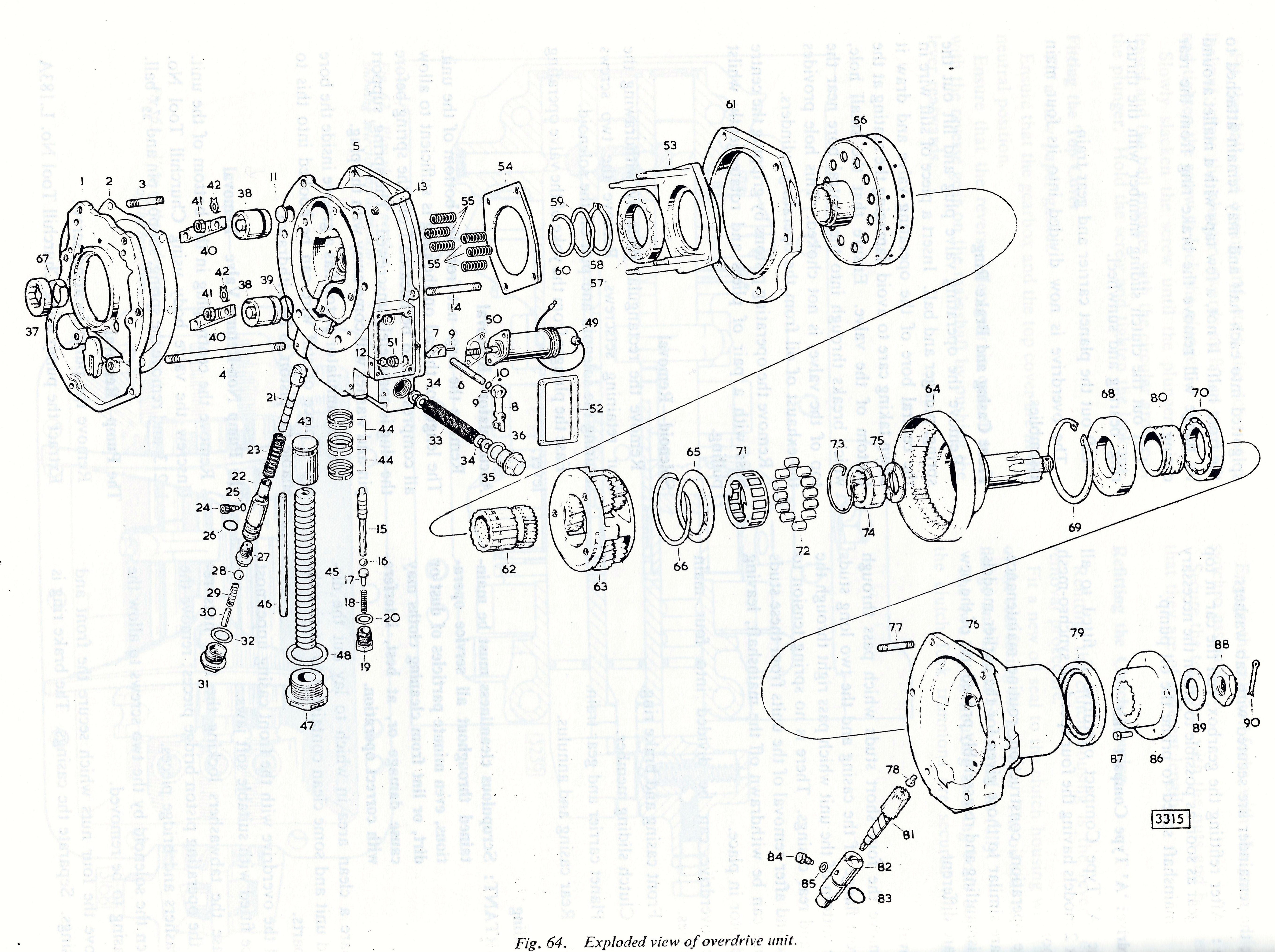
MK2 Overdrive
Mike Gassman, http://www.gassmanautomotive.com refreshed the overdrive and the gearbox was sent to Quantum Mechanics in Connecticut. Both units were in good repair with the exception that the 3rd to fourth shift fork was bent and was replaced. The gearbox also had all bearings, synchronizers, seals and gaskets replaced. The gears were in good shape. The overdrive was cleaned, an overdrive rebuild kit installed and reassembled in good working order. A new solenoid was affixed and the system was tested.
Change-Speed Lever Assembly (Gear Shift) The change-speed lever has single flat washer above the selector lever.
There is a two part rubber bush inside the selector lever through which the selector shaft passes. There is a flat washer at each end of the bush. The washers have different diameter holes appropriate to the shaft size at each end of the lever. I cleaned the selector lever and painted it with POR-15. New rubber bushes were also installed.
Change-Speed Lever
Selector Lever
Painted Selector Lever
Assembly Components
There is a bronze bushing in the selector lever through which the pivot pin passes. This bush was also replaced with a new component. A new fiber washer is located on each end of the pivot pin. A double spring washer is located on the pivot pin and the assembly is held together with a slotted nut and a split (cotter) pin.
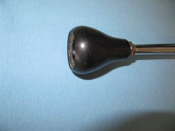
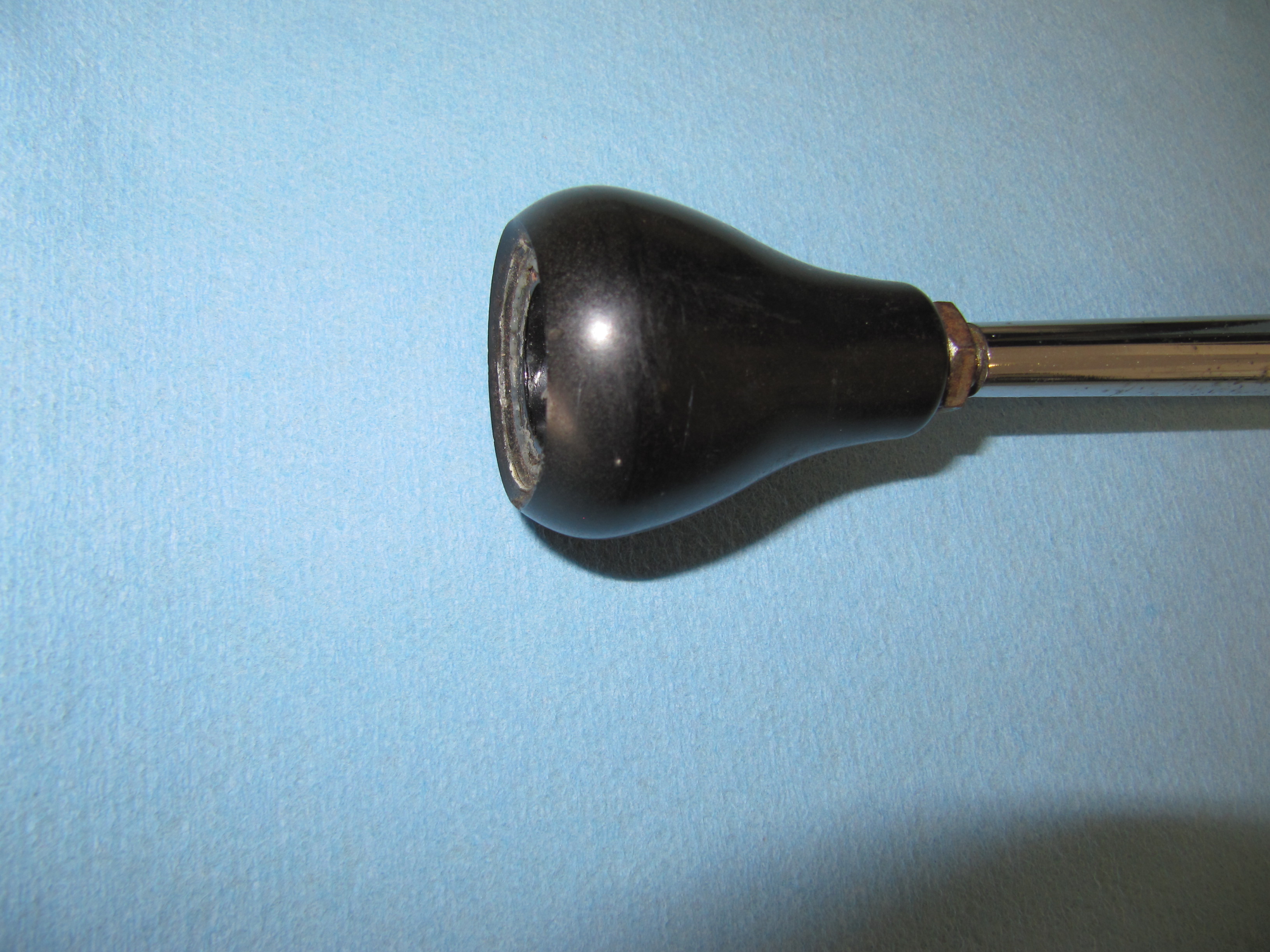
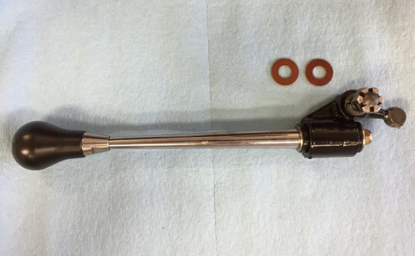
Change Speed Lever Knob
The correct lever knob for the early Moss gearbox (without first speed synchro) is a tear drop shape. The later box used a round shifter ball. A locking nut secures the shift knob to the shaft.
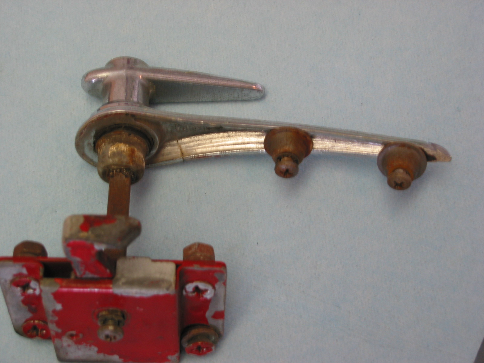
I ordered a new lever shaft and discovered that what is being supplied now is 3 inches shorter than the original. I will probably have my original lever shaft rechromed and use it.
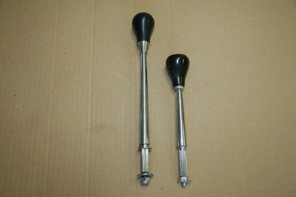
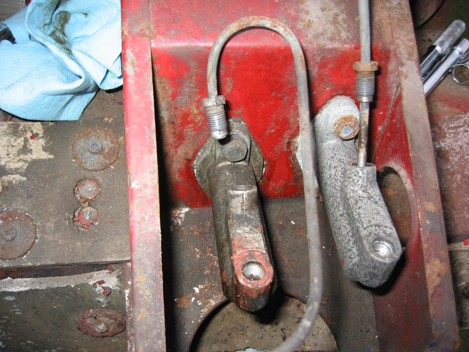
Original Shifter on Left and New Part on Right
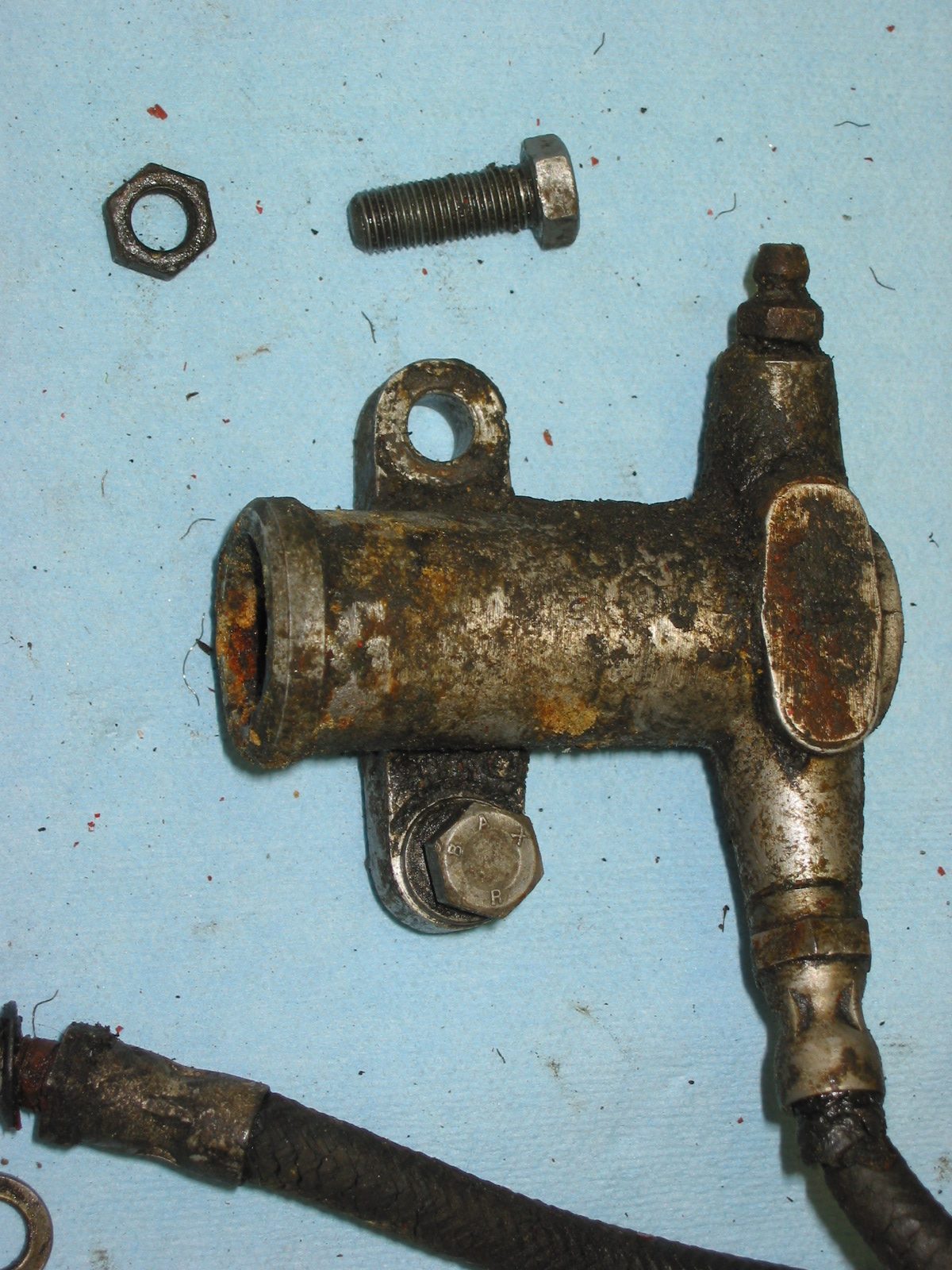
Pivot Jaw Holding Selector Lever
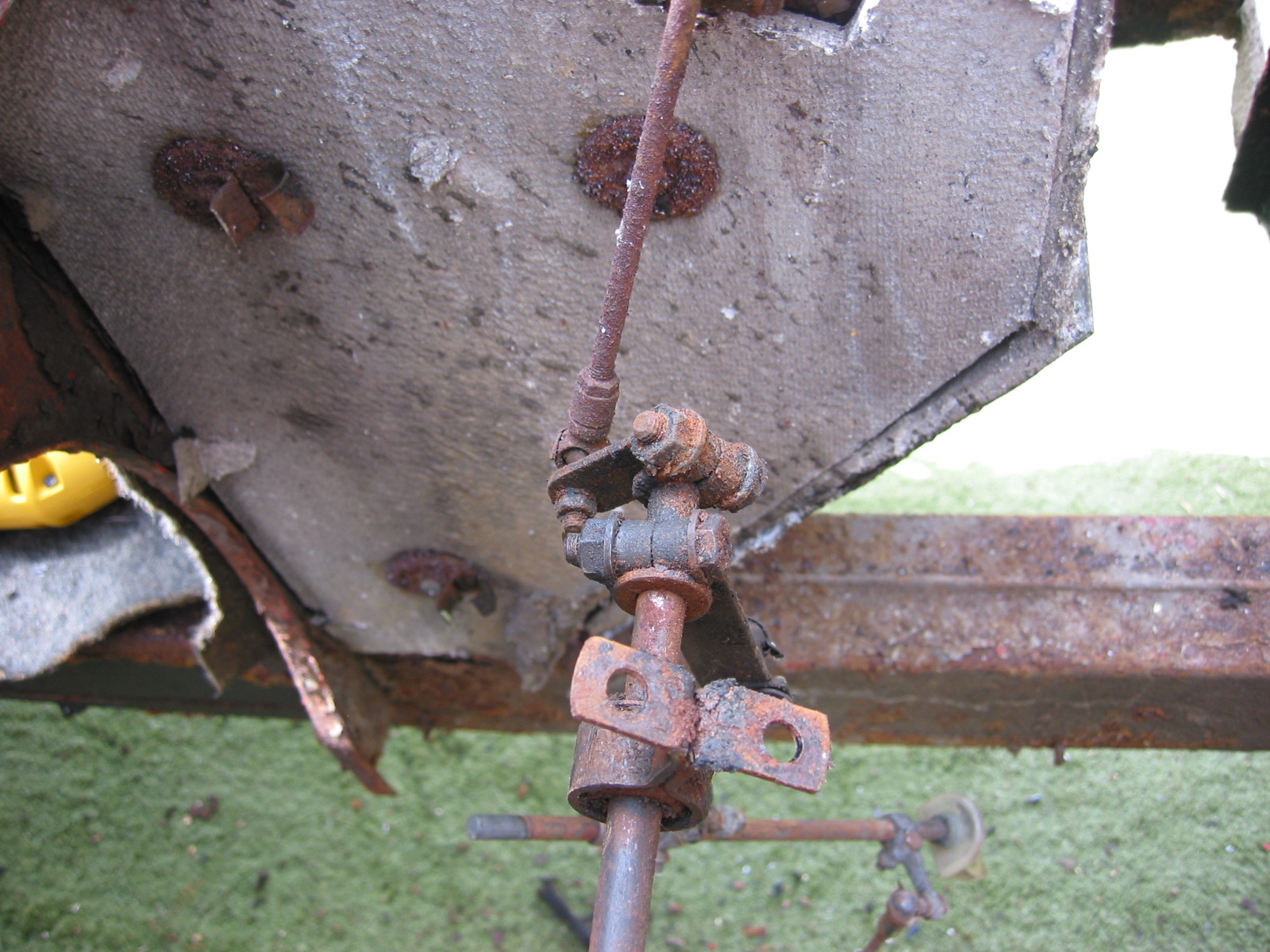
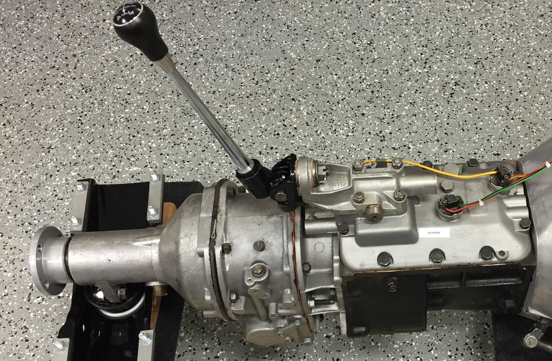
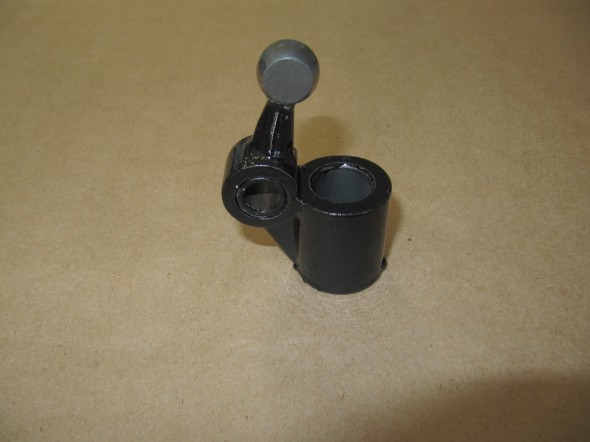
This device connects the Change-speed Lever (gear shift) to the Gearbox Top Cover. In the image below it is the black yoke which was cleaned and painted with POR-15.
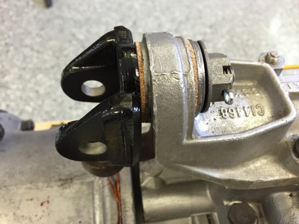
Pivot Jaw Housing Selector Lever
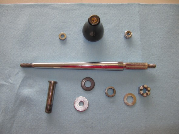
The following image shows the components of the Pivot Jaw assembly: The Pivot jaw, two fibre washers, a bushing, a flat “D” washer, a spring washer and a slotted nut with split pin.
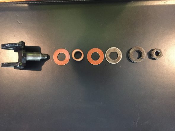
Pivot Jaw Assembly Components
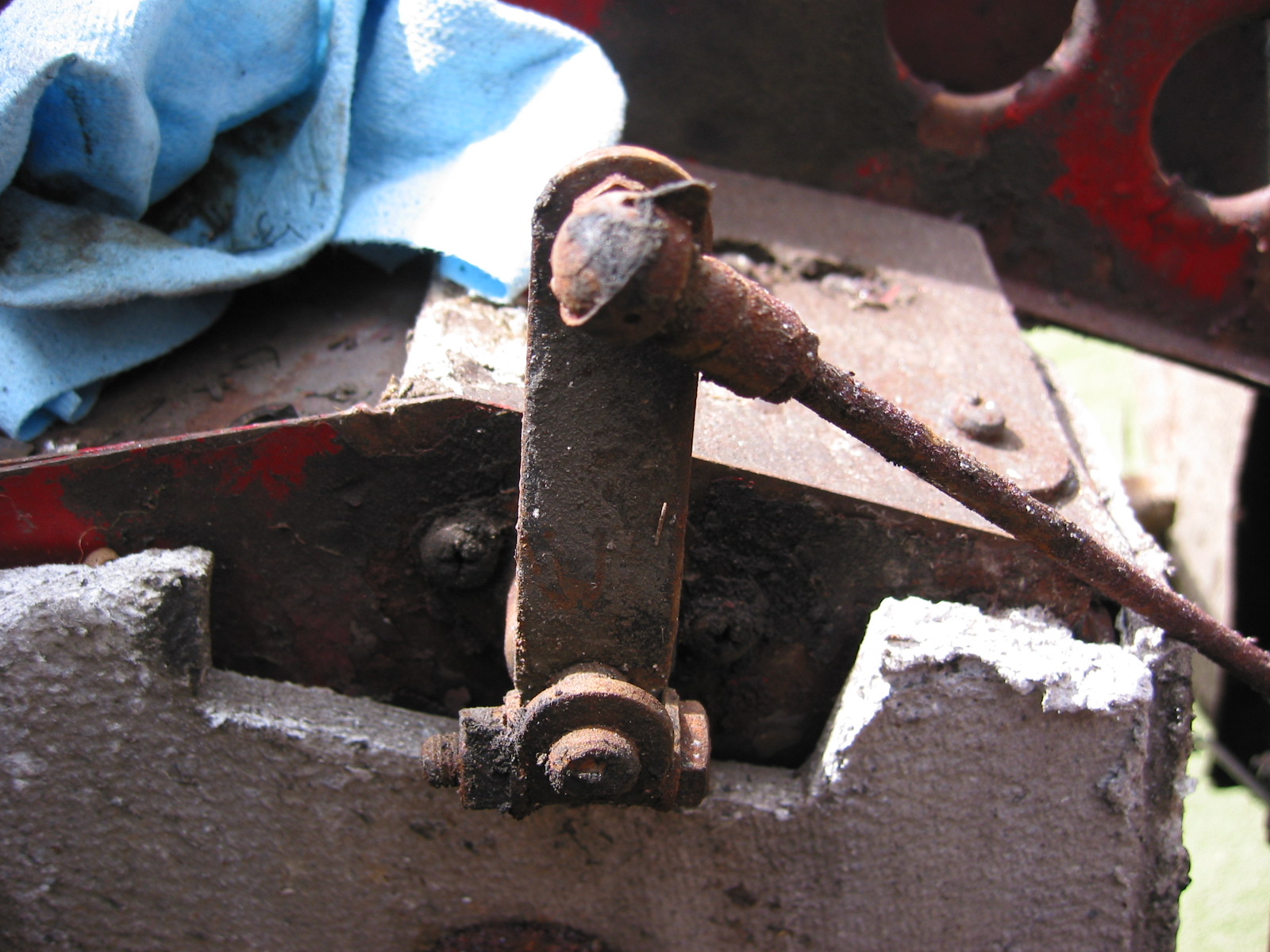
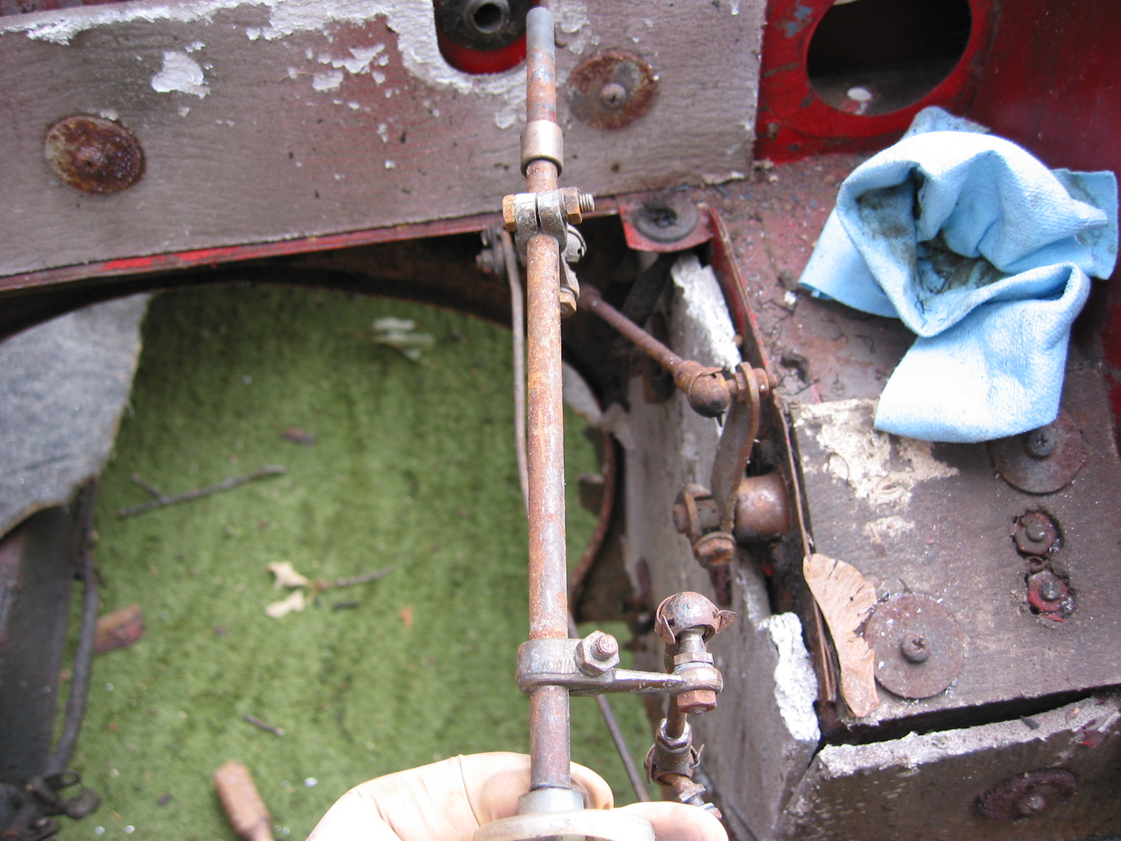
This image shows the Pivot Jaw Housing, the Change-speed Lever, and the Selector Lever all assembled and in place on the gearbox:
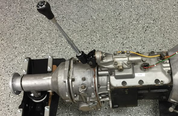
Assembled Gear Selector Assembly
Fasteners for Gearbox to Engine The original fasteners were in good shape, no doubt due to the thick coat of oil and grease that encapsulated them! I media-blasted the bolts and nuts and had them zinc plated for use upon reassembly. There are eleven hex head bolts 3/8″ – 24 x 2 7/8″ with two 3/8″ – 24 nuts and shakeproof washers, and four 3/8″ – 24 x 1 3/8″ hex head bolts with four 3/8″ – 24 nuts and shakeproof washers.
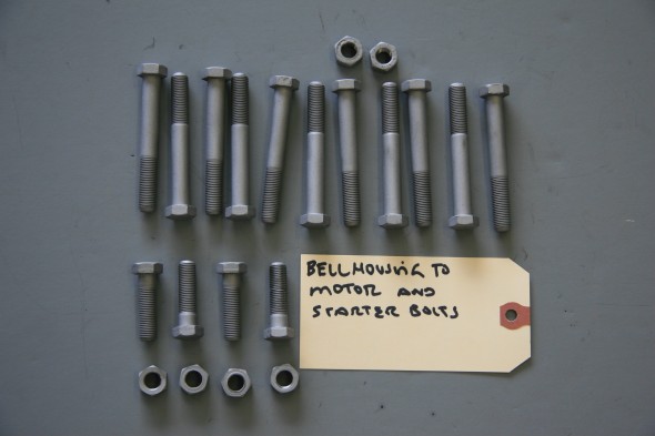
Bellhousing fasteners
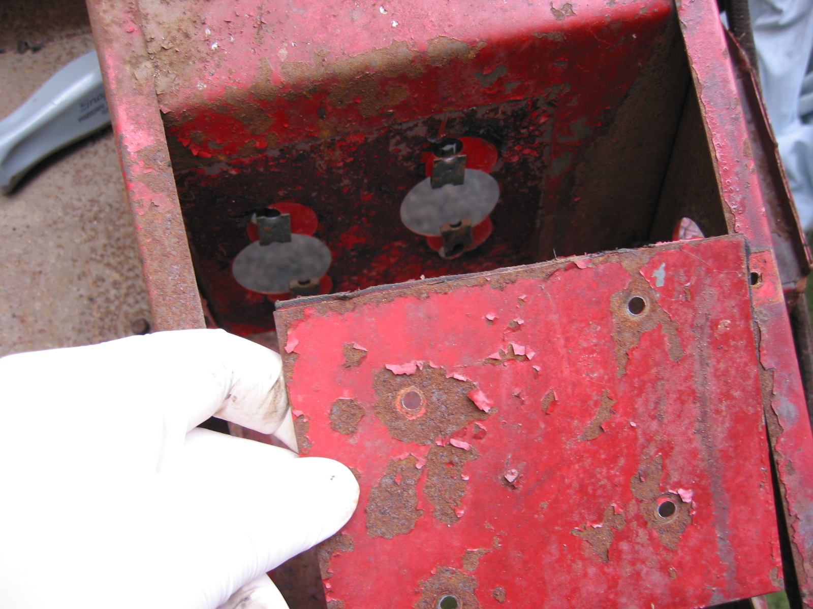
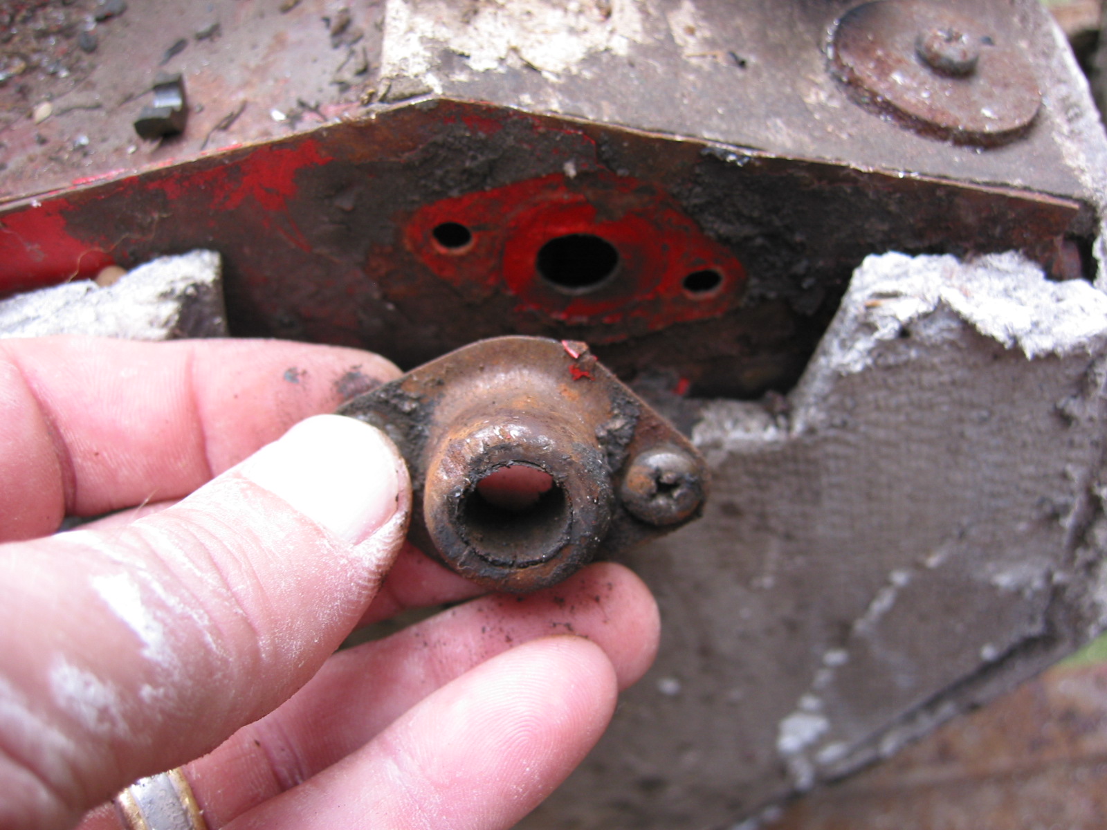
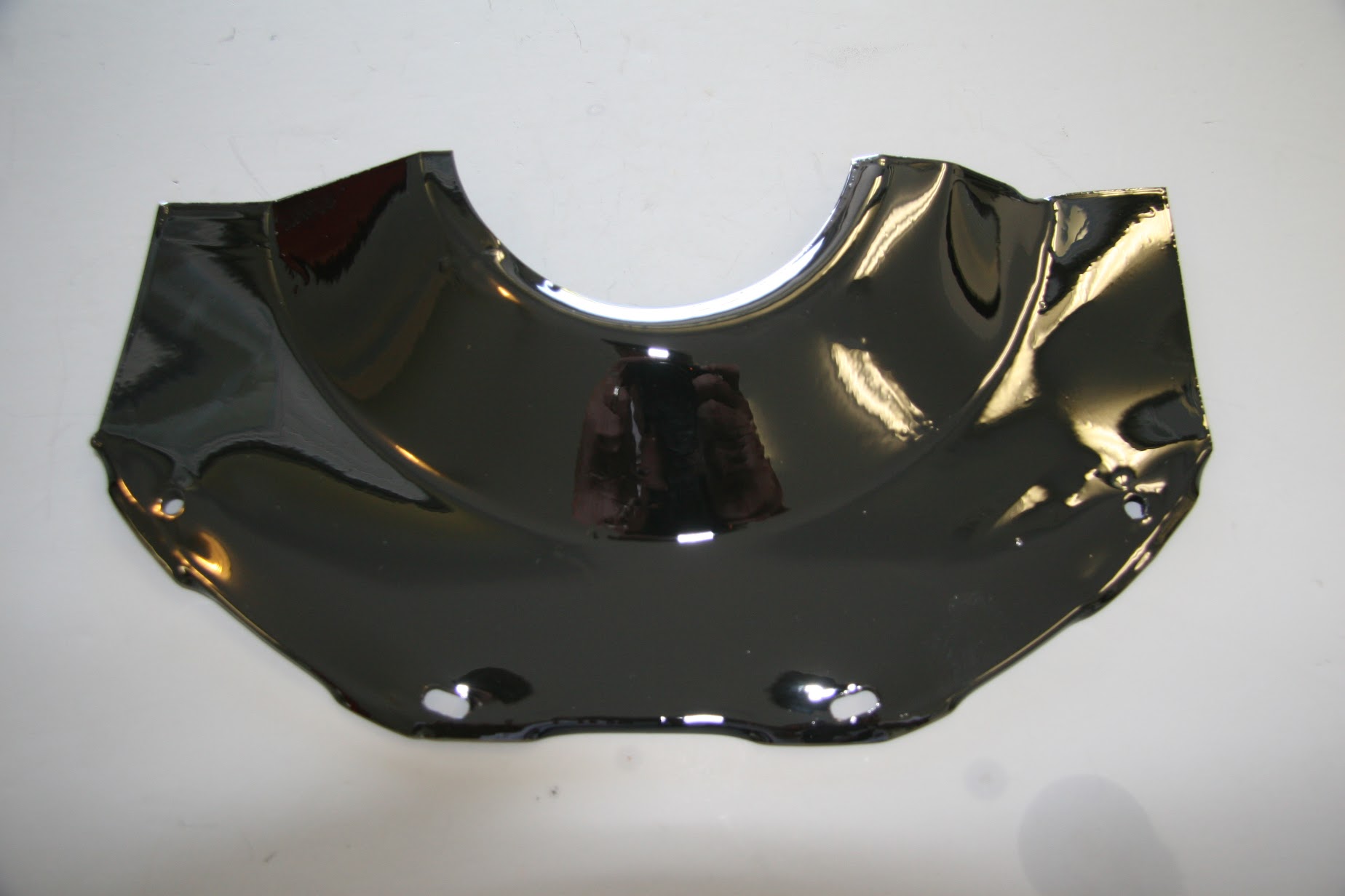
Cover Plate at Front of Clutch Housing The cover plate is fastened to the engine backplate with four #10-24 x 1/2″ hex head bolts and shakeproof washers. It is installed when the gearbox is mated to the engine when the two components are separated by approximately 2″. At that time the cover plate is slid into position and tightened against the lip of the gearbox bell housing with the four bolts.

Clutch Cover Plate
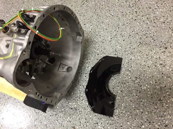
Clutch Cover Plate at Bell Housing
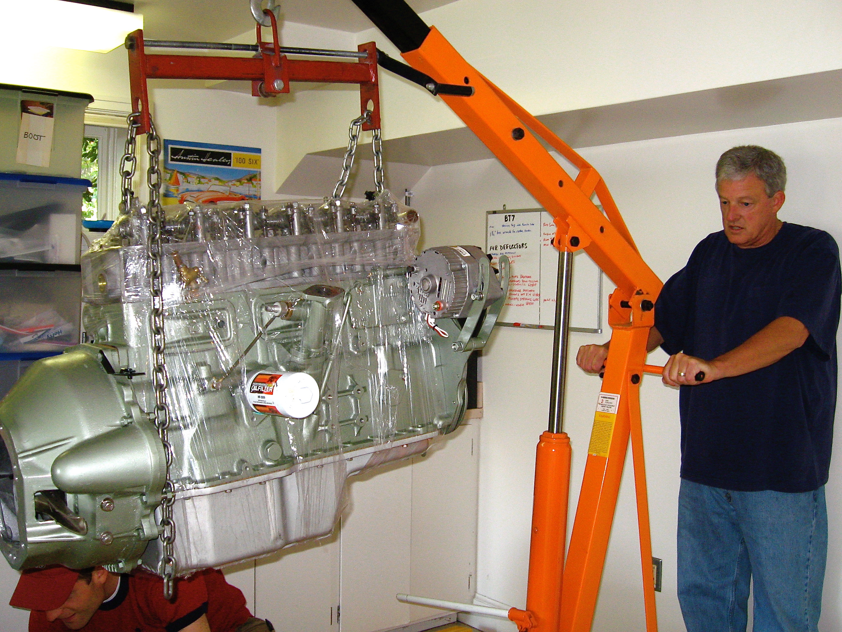
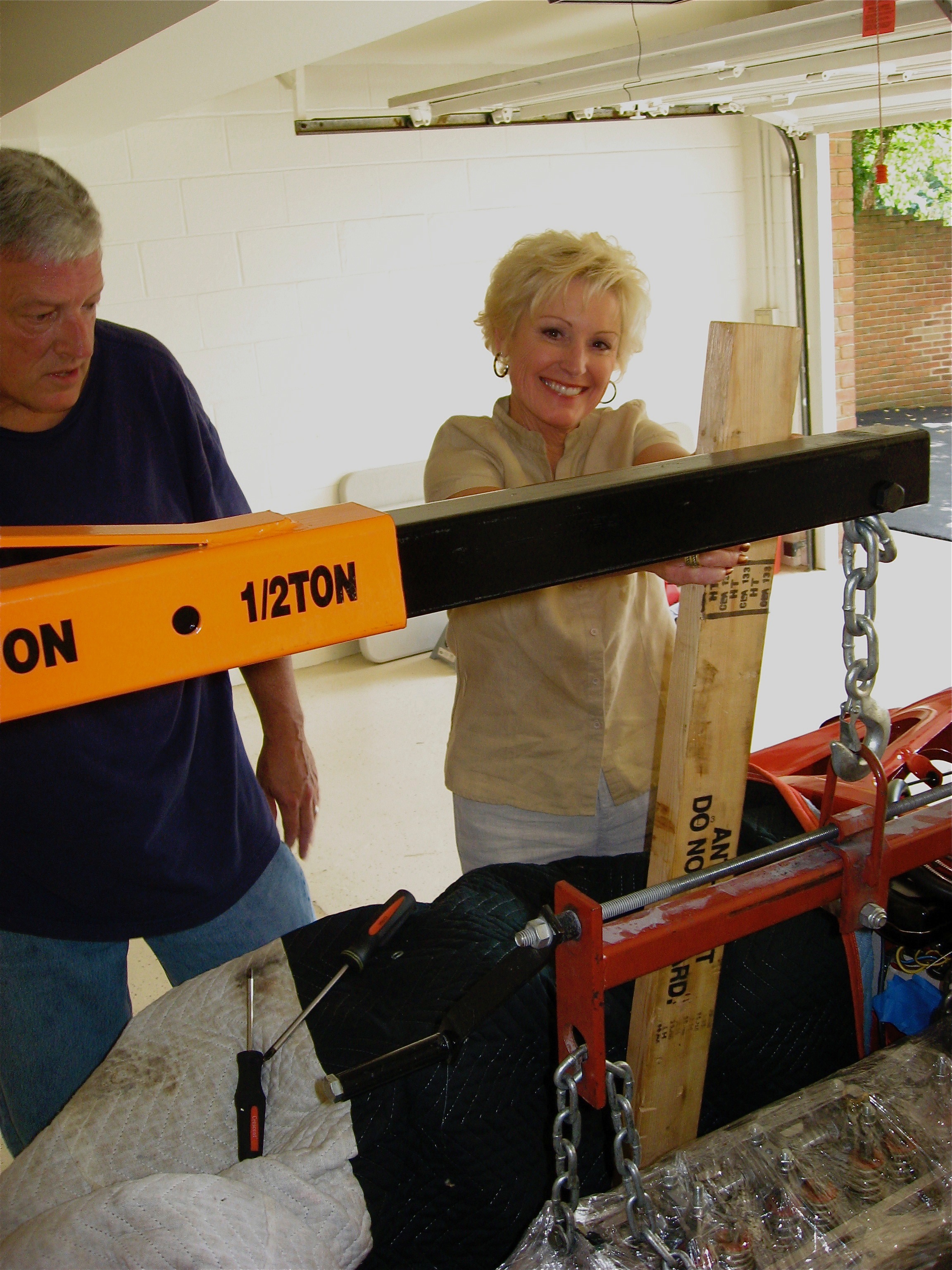
Gearbox/Engine Mating
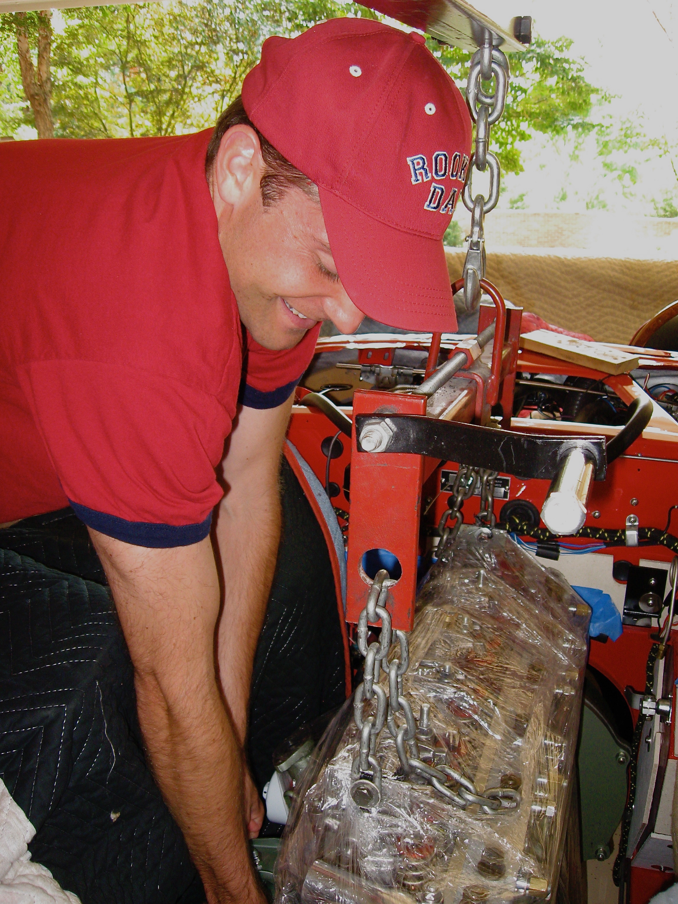
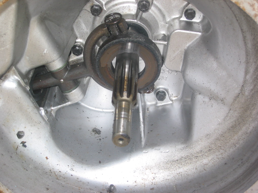
On June 18, 2016 in preparation for the preliminary installation of the engine and gearbox into the car for testing, I mated the two components together using the bolts referenced above. In the cases where nuts are used, all nuts are found on the bell housing side. I had to wrestle with the gearbox a bit to get it to seat properly, but I eventually got there. One must be careful to keep the gearbox mainshaft level with the crankshaft to avoid bending the shaft.
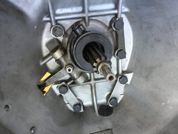
Gearbox Mainshaft
I used my engine hoist to hold the gearbox at proper height during the exercise. Several long 3/8″ bolts were used to align the bell housing and the backplate of the engine, prior to inserting the proper bolts and pushing the gearbox home. As mentioned above, then the two components are approximately two inches apart, the clutch cover needs to be inserted and bolted in place.

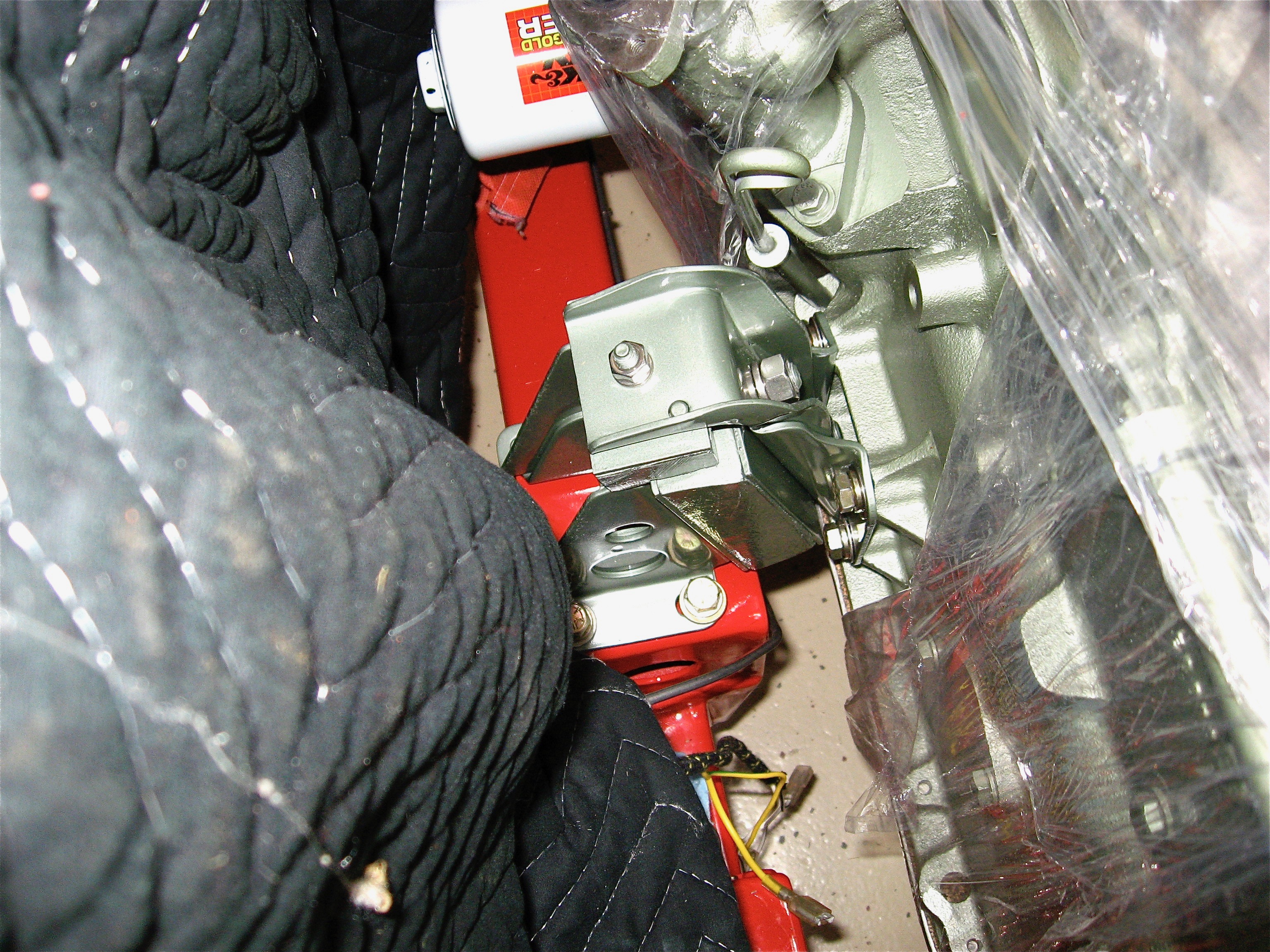
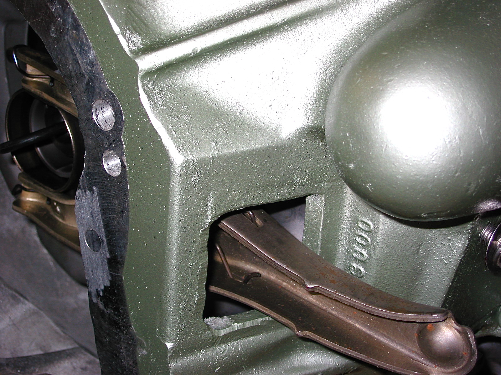
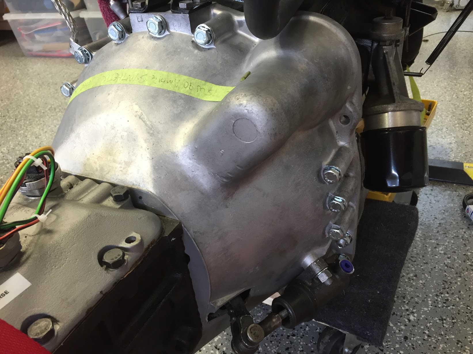
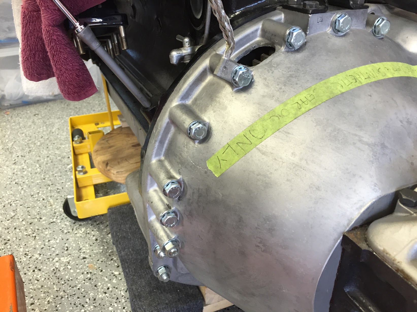
RH Side of Bell Housing Mounted to Engine

LH Side Of Bell Housing Mounted to Engine
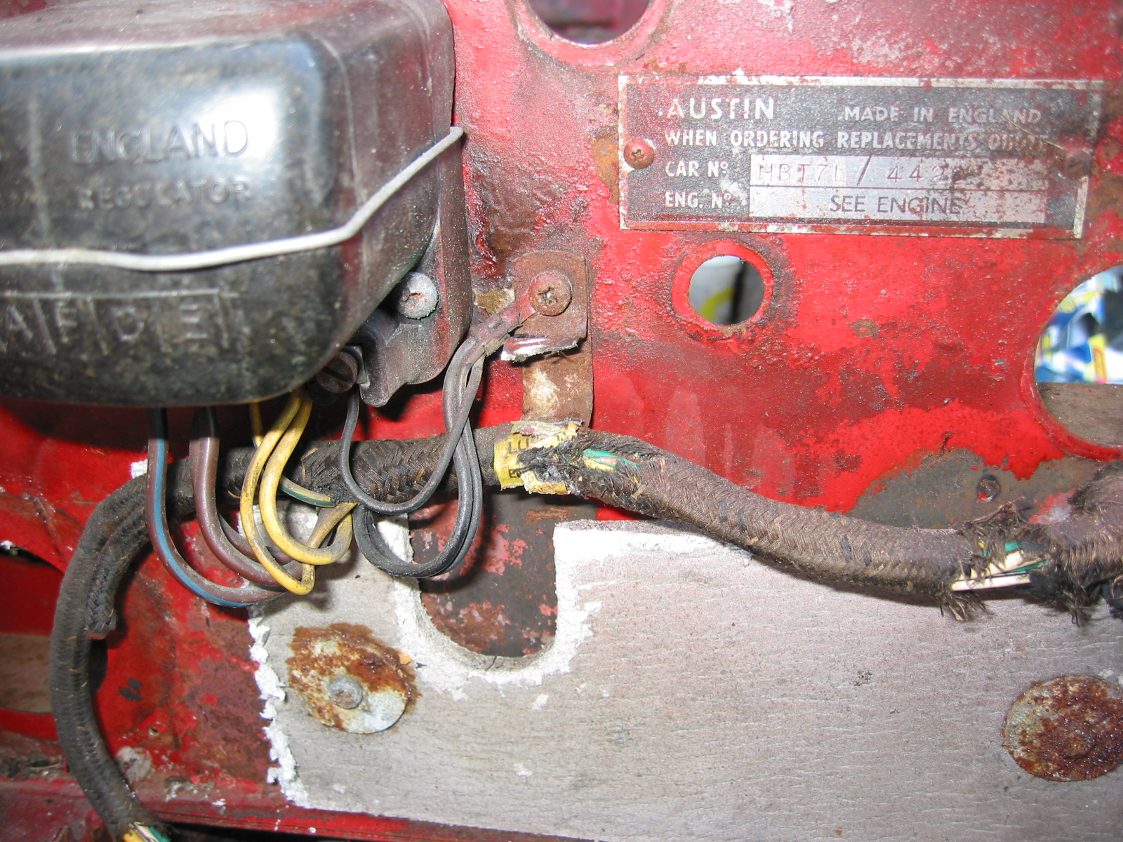
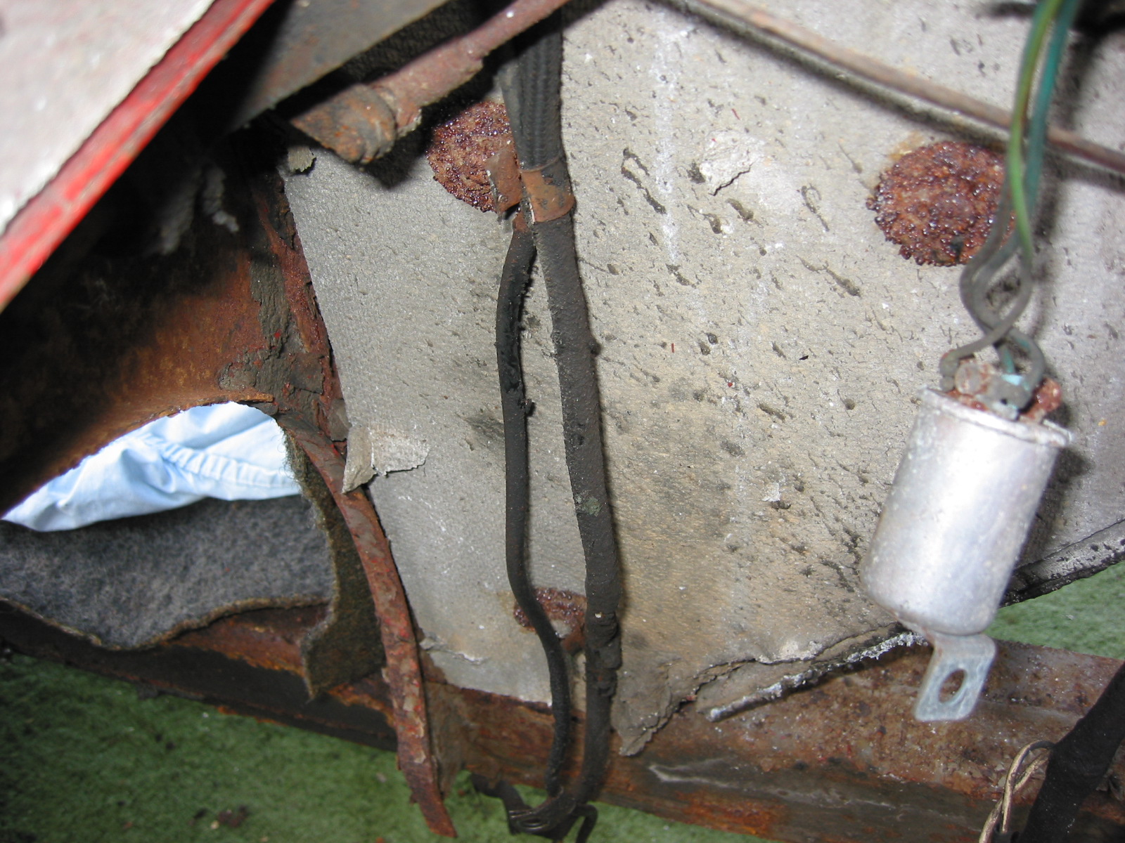
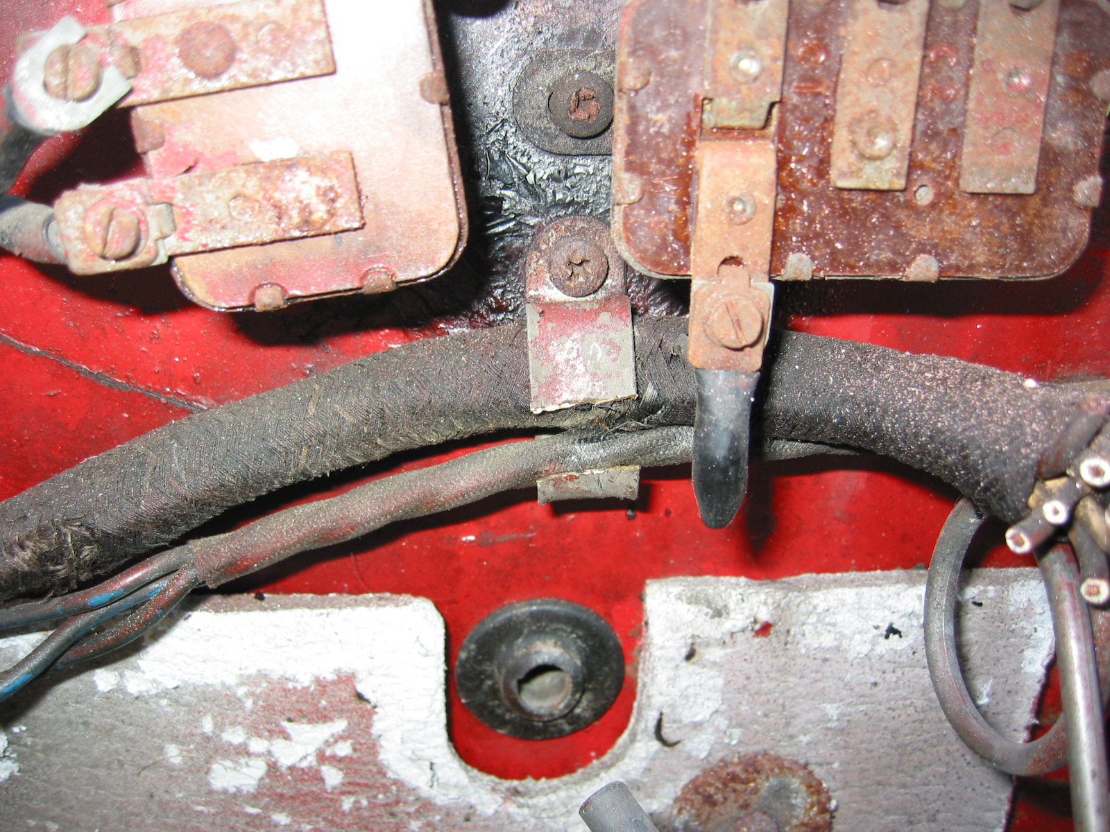
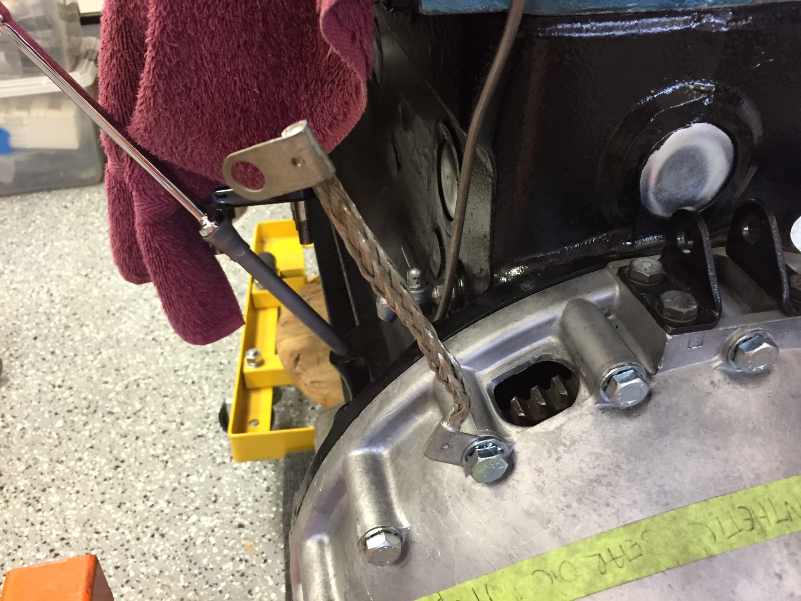
Ground Strap
The ground strap was connected to the engine/bell housing prior to installation in the car. A new ground strap was sourced from SNG Barratt. Note the proper location of the strap:

Ground Strap Mounted
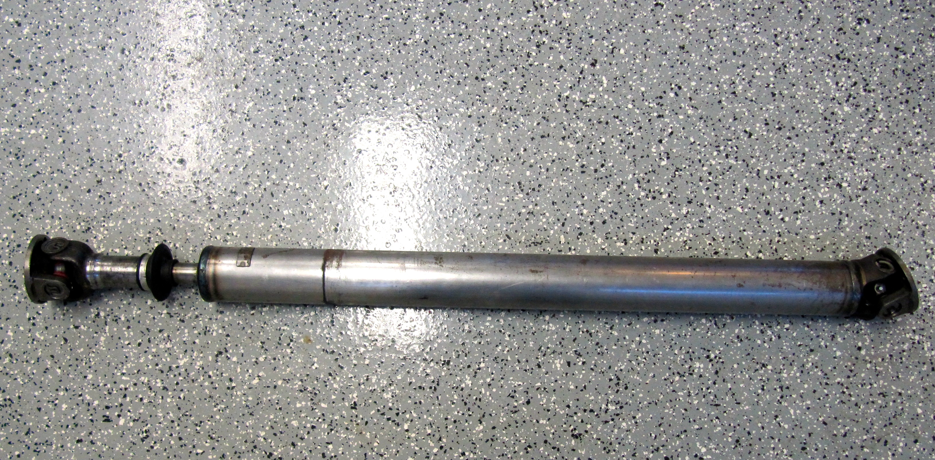
Propshaft
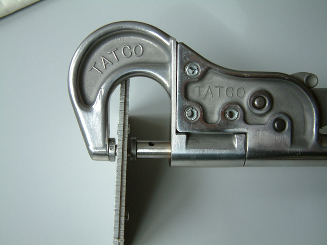
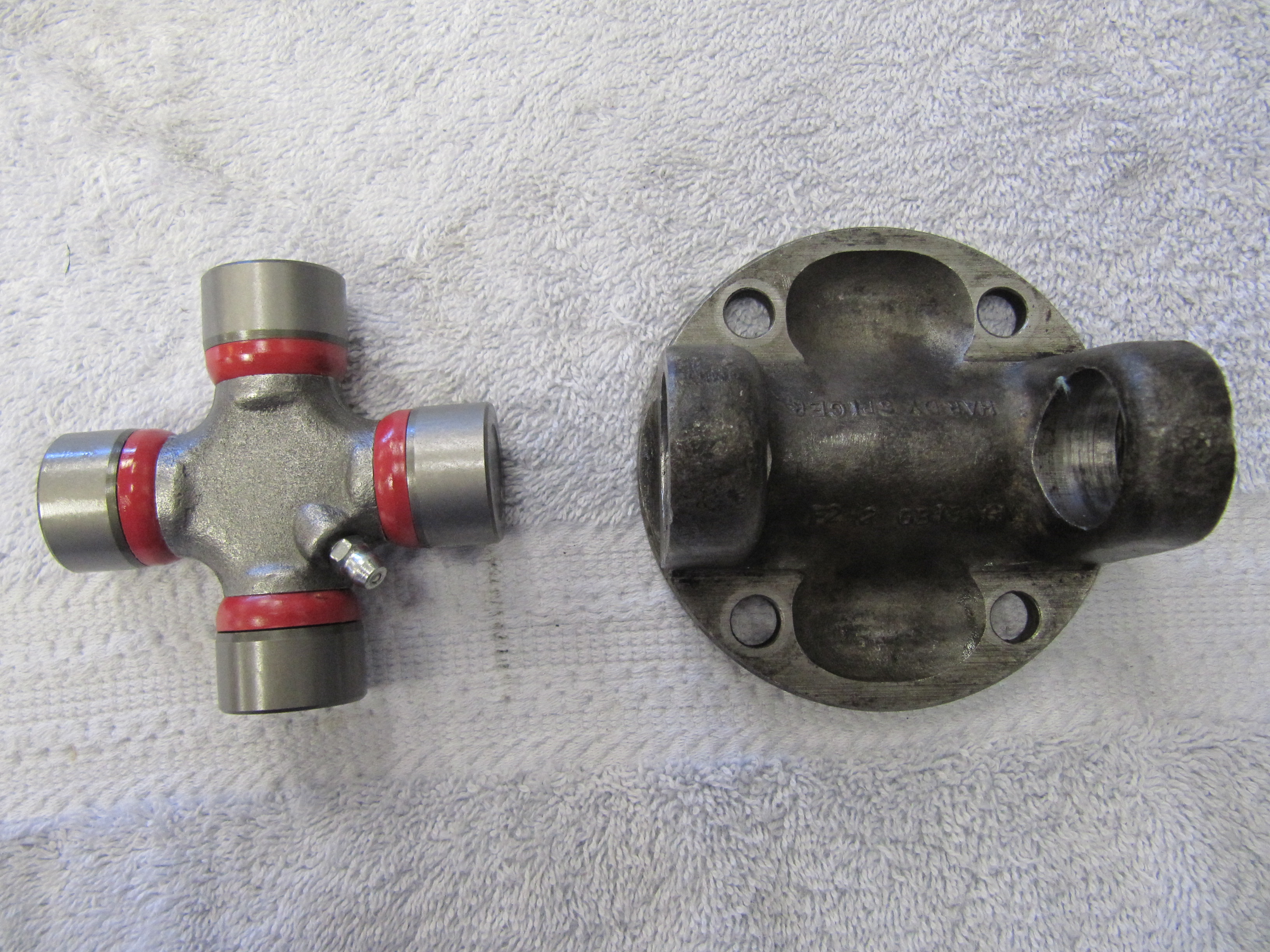
The propshaft with the two flange yokes attached is just under 48″ long. The shaft seems to be in good shape, but I went ahead and replaced the two universal joint journals and bearings. Following installation of the universal joints I greased the two units and then cleaned the shaft well to send to Driveshaft Specialists in San Antonio, TX http://www.driveshaftspecialist.com (Jeff, 866-455-6622) for balancing.
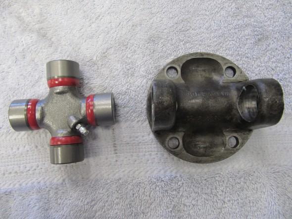
Universal Joint Replacement
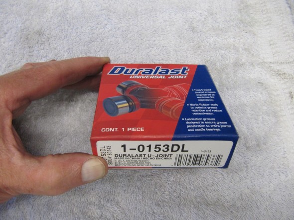
Duralast Universal Joints
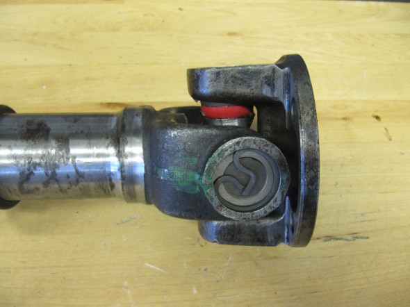
Universal Joints Installed
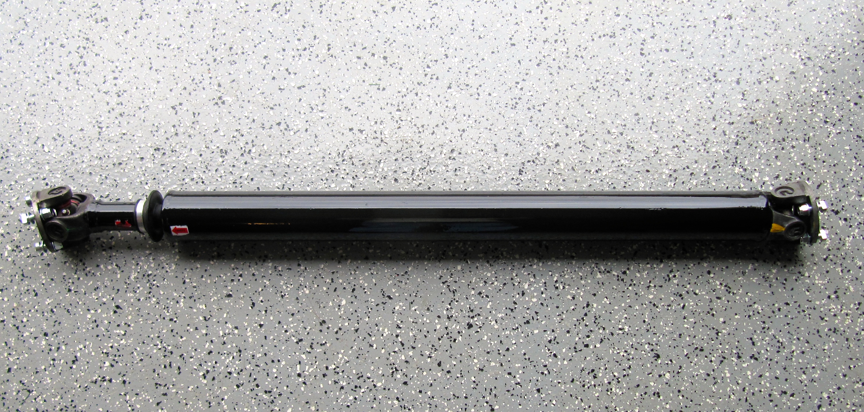
Upon return from Driveshaft Specialists, I painted the propshaft with POR-15.
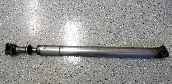
Propshaft with new Universal Joint
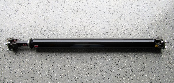
Balanced & Painted Propshaft
Gearbox/Overdrive Lubrication
After installing the engine and gearbox in the car I filled the gearbox and overdrive with oil. Mike Gassman, at Gassman Automotive, recommended using Amalie Elixir Full Synthetic GL-5 Gear Lubricant. The Jaguar MK2 Service Manual indicated that 4-3/4 pints of lubricant should be used.
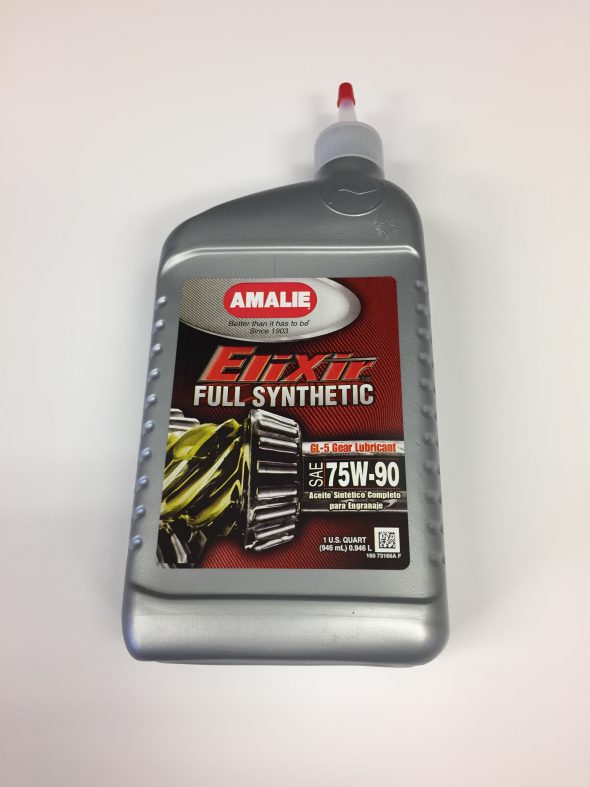
Amalie Elixer Full Synthetic GL-5 Gear Lube 75W-90
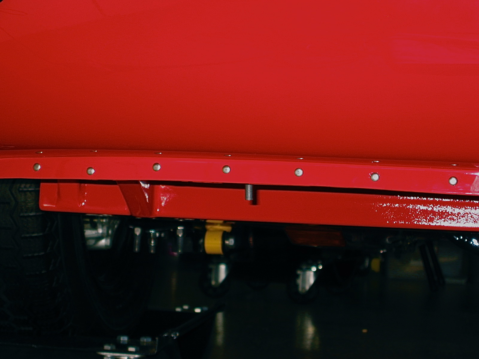
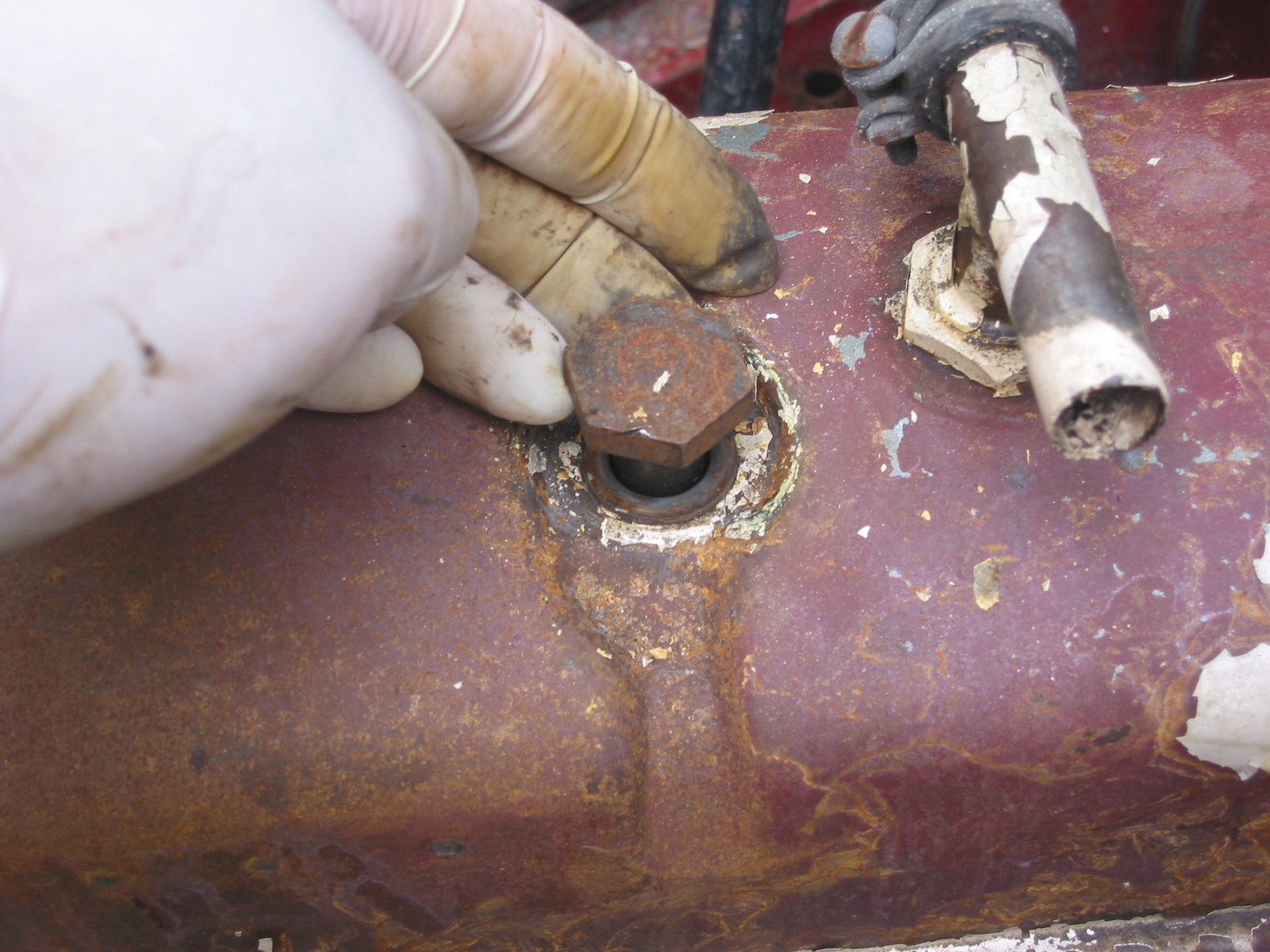
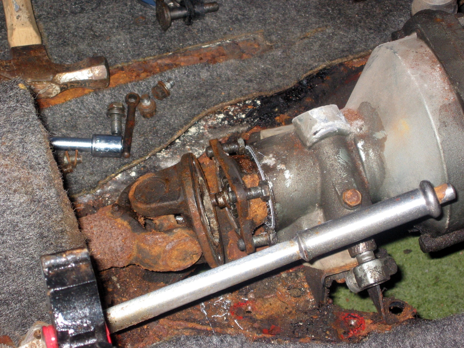
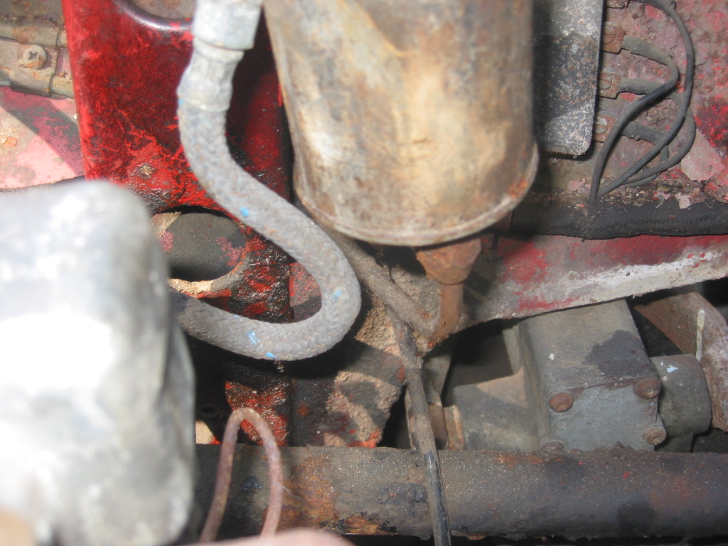
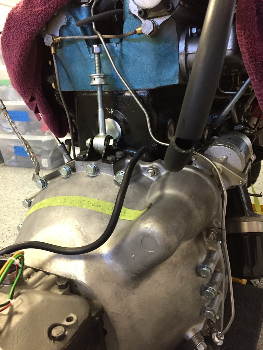
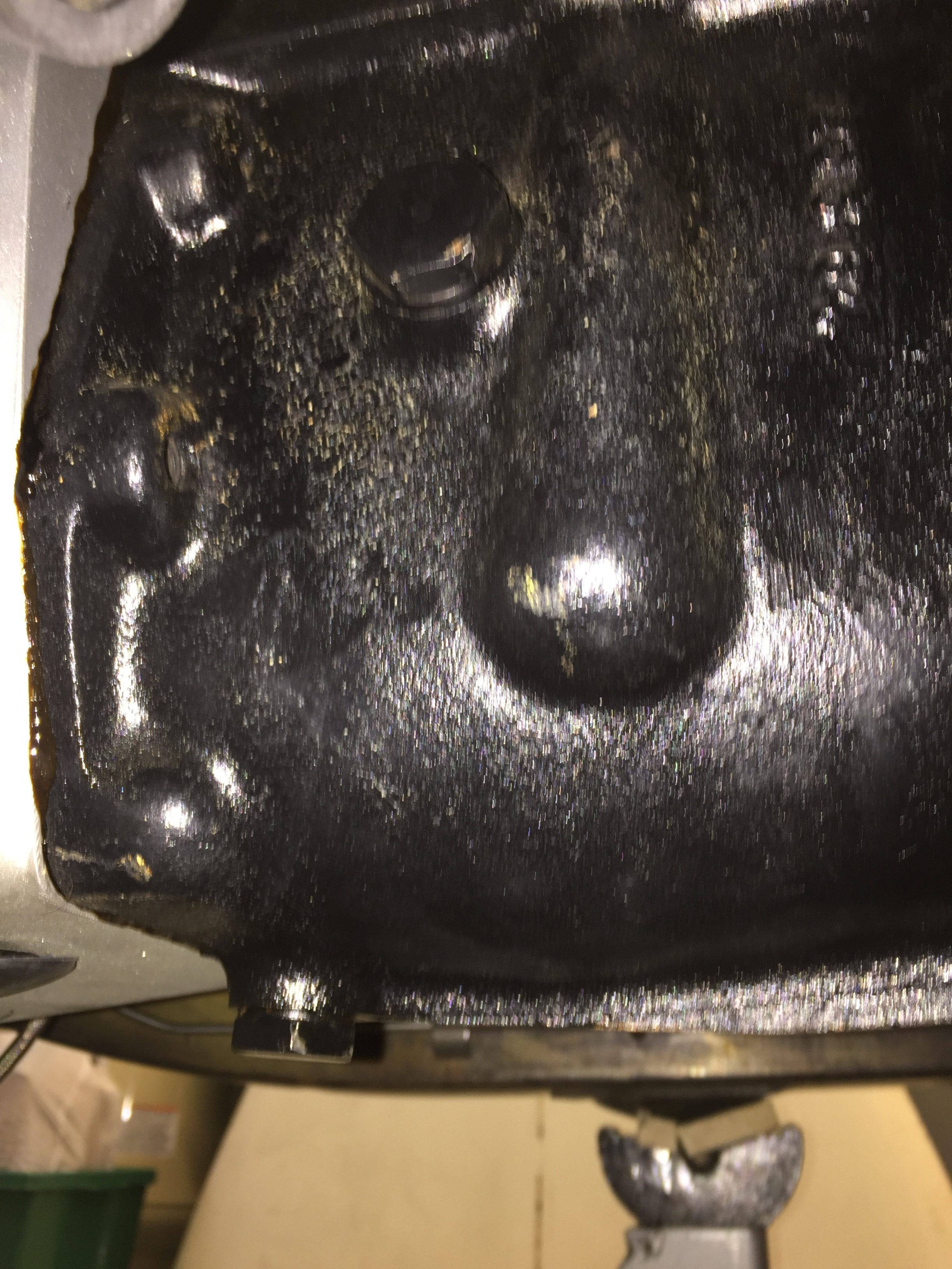
This image, although a little out of focus, shows the fill plug near the top and the drain plug at the bottom of the gearbox. The overdrive fills though an internal hole from the gearbox to the overdrive.

Drain and Fill Plugs for the Jaguar MK2 Gearbox
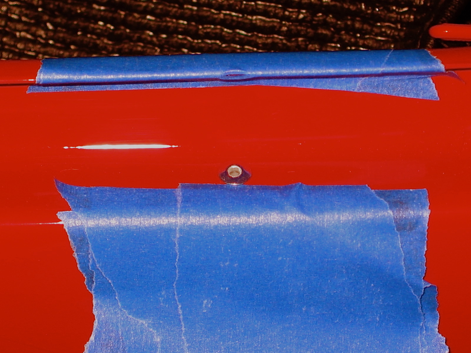
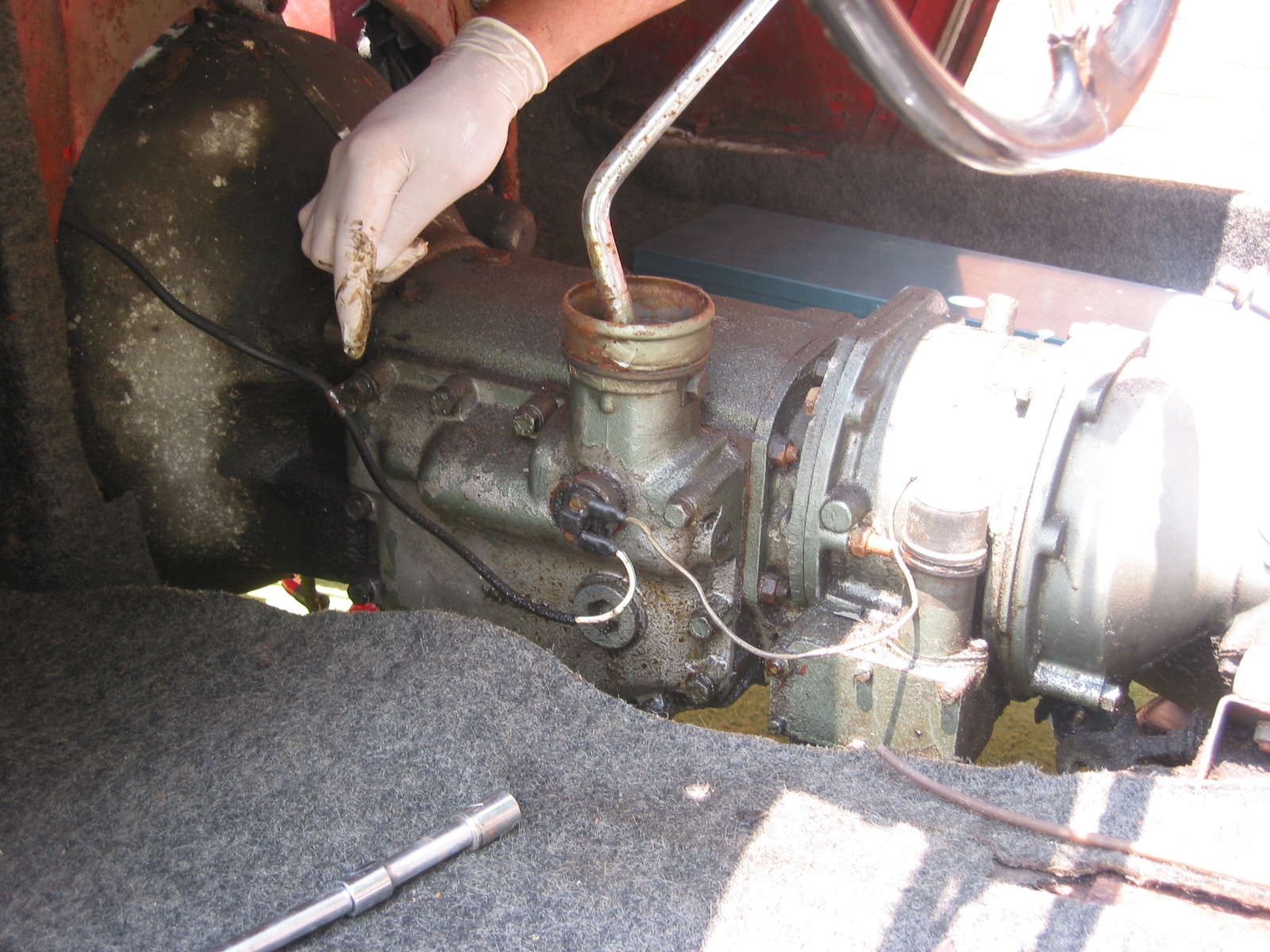
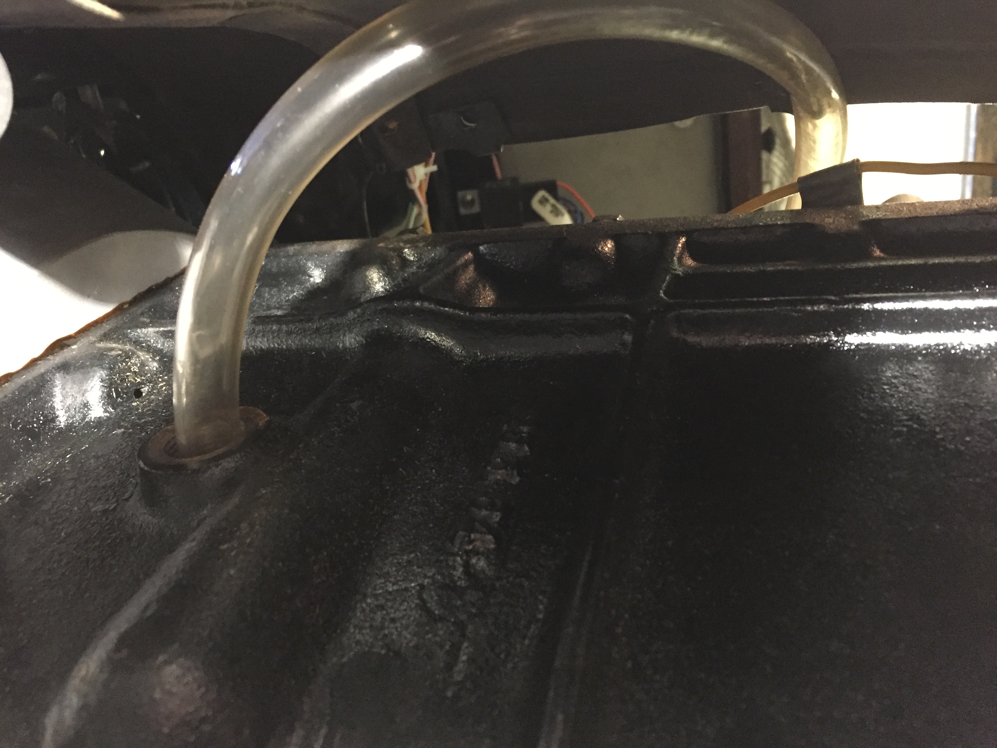
While I could have used my hand pump to pump the gear lube from below into the fill hole, since my interior is not installed I removed the fiberglass gearbox cover and filled from above. I inserted a clear tube into the fill hole and routed it to the interior. I found that it actually took a little closer to 4- 1/2 pints to fill the units, even after waiting some time to allow the fluid to flow to the overdrive. I filled the gearbox until the gear lube began to leak out of the fill hole.
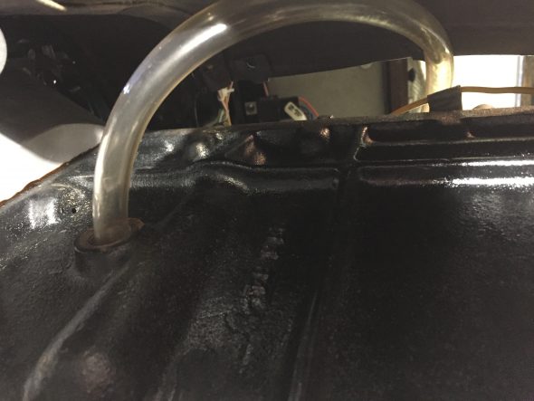
Fill Tube for Gearbox