Luggage Rack Lexan Boot Lid Shield

I have a Cape International luggage rack on “The Bloody Beast” and I am very pleased with its looks and functionality. One of the features I like best is how closely the rack “hugs” the contours of the boot lid; however, the curvature of the boot lid makes it quite possible for items carried on the rack to rub against the paint with the possibility of ensuing paint damage. This is especially true if you desire to carry something like folding chairs in bags that are not completely flat. To protect the paint I developed the folding transparent (and waterproof) plexiglass shield shown below. The folding joint in the Lexan allows me to fold the glass in half for easy stowage in the boot when not in use.

The hinge folds 180 degrees. Ordered from McMaster-Carr, 11565A11, Clear Acrylic w/White Polyester Middle. Lexan is 1/4” thickness and is quite rigid.

Luggage Rack Shield Image 1

Luggage Rack Shield Image 1

Luggage Rack Shield Image 2

Luggage Rack Shield Image 2

Luggage Rack Shield Image 3

Luggage Rack Shield Image 3

Luggage Rack Shield in Place

Luggage Rack Shield in Place

Chapter 69 Assembly Week Thirty-Nine September 10, 2007

The next job to be tackled was the installation of the rivets for the rear shroud to the frame. There are 19 aluminum flush face rivets for the lower lip of the car and another 13 rivets that attach the shroud to the rear boot frame rail.

First, I put a healthy bead of 3M body caulk between the two pieces to keep water out of the boot. I clamped things together as best I could and inserted pop rivets in the frame rail just to line the components up properly. The aluminum rivets for the lower lip were sourced from British Car Specialists. I purchased a rivet squeezer tool from Brown Aviation Tools with the 2003-16 1/8” rivet set to use for the job. An expensive tool at $135 for one little job! The tool worked nicely. After an initial “squeeze” with the tool, I put five small #10 washers on the rivet set to pull them closer together and squeezed the rivet again. I ended up with a very satisfactory job. As per original specifications, I then painted the lower lip satin black.

Rivet Squeezer

Lower Rivets installed

There just wasn’t room to use the rivet squeezer for the boot rail-to-shroud assembly so I used 1/8” diameter, 1/4” long aluminum pop rivets for the job. The nose of the rivet gun wanted to hit the boot lip so I put about three thicknesses of blue painter’s masking tape around the area to protect the paint. I did get two small nicks that were touched up, but otherwise the project was a success. It pays to take your time on the rivet job if you are assembling after painting.

Rivet paint protection

Pop Riveter

Pop Rivets installed

Following the rivet work I installed the rear bumper bars and rally bumpers supplied by Cape International. New rubber grommet seals were installed on each bar, paying attention to the LH/RH designation. I am very pleased with the look of the rally bumpers, although one is not afforded much protection by these full bumper replacements!

Rally Bumpers

The next task was to install the boot lid. This turned out to be pretty easy. Again I protected the body with some blue painter’s masking tape and with the help of my wife, put the lid in place and tightened down the boot hinges. After getting the lid in place, I needed to adjust the boot lid striker so that it would fit properly to latch the boot lid. I then attached the boot lid control cable to the lower hinge post and I was in business!

Boot Lid Installed 2

Back End Finished

Before the final installation of the engine, I decided to fit the clutch assembly and Smitty Bellhousing to the block and put in the car to make sure the clutch was working properly. I wanted to make sure that I had sufficient room for the clutch fork to function once connected to the slave cylinder. Some might call this a little anal, but if you install with just the bellhousing and not the gearbox, you can view everything to ensure success later!

Clutch Fork 1

Clutch Fork 2

Clutch Fork 3


Chapter 66 Week Thirty-Six August 20, 2007

I went out to visit Jack at Coach Works and check on the progress of the motor assembly. I was pleased to find that he had mounted the spin-on oil filter, the alternator with the bracketing kit from Hendrix Wire Wheel (made by Don Lenschow), the rebuilt original water pump and pulley from World Wide Auto, the tach drive, the harmonic balancer and crank pulley, the oil feed line, the drain valve, the head gasket and Denis Welch aluminum head, the chain tensioner and timing chain, the timing chain cover, the tappet covers and the aluminum oil sump from British Parts Northwest. The BPN aluminum oil sump bolted right on with no adjustment required of the oil strainer or drain pipes.

Spin On Oil Filter

Water Pump and Alternator

Tach Drive

Coolant Drain Valve

Tappet Covers

I failed to mention in earlier posts that I had ordered and received a new aluminum head with valves, springs and etc. from Dennis Welch Motosport. I ordered the “Fast Road” version. Yes, it did make me happy

A present for myself!

Aluminum Head Tech Sheet

You got it!

New Studs

I got over my fear of touching the rear shroud! I placed it on the superstructure and bolted it on through the two steel threaded mounting plates near the front of the shroud. I then clamped the bottom lip in the rear

Fitting Rear Shroud

Fitting Rear Shroud 4

I mounted the rear reflectors that I had converted to lamps A-H Reflector conversion Charlie Baldwin and the rear lights/turn signals.

Rear Lights

Rear Lights 2

I discovered one reality the hard way. On the left turn signal lamp you have a red wire, a white with purple wire, and a black wire (the right lamp is the same except the white wire has a brown stripe in it rather than purple). These red and white wires must go to their proper terminals or you won’t end up with the turn signals functioning properly. I also learned that those chrome trim rings can be a pain to install in the rubber lamp boots! Patience is required along with tools like a wooden cuticle tool and dental picks. I am sure they had those on the assembly line.

After installing the lights, I put the tenax studs in place for the soft top and tonneau. I used a leather washer against the car paint and then a nylon washer to lift the stud away from the paint slightly.

Tenax Stud

Next, I installed the fuel tank filler pipe and the aluminum Aston flip-top fuel cap. Not original, but I sure think it adds a nice touch!

Fuel Filler Pipe Joint

Aston Fuel Filler Cap 3

 There are three rubber buffers that are inserted through the rear shroud and the frame hoop to help set the height of the boot lid on the shroud.

Boot Lid Rubber Buffers

I am going to wait another week or two to install the boot lid on the car, but I went ahead and attached the locking boot handle, the “Austin Healey” script badge and the “3000 Flash”. I also attached the prop rod rubber clip and the lock. I purchased stainless prop rods and prop rod stay brackets for the boot lid and bonnet from Wicker’s Paint and Body Shop (Unfortunately, no longer in business).

Boot Lid Hardware

Stainless Prop Rod

Prop Rod catch

Prop rod stay bracket 2

Chapter 65 Week Thirty-Five August 13, 2007

Rear shroud and boot lid.

Jeremy returned from vacation and painted the rear shroud and boot lid. I picked them up and they do look beautiful. I am reminded of that feeling I had when he unloaded the frame and superstructure from his trailer at the house. I am afraid to touch anything for fear of damaging the paint. As before, I suppose with time I will get over it.

Chapter 30 – Cleaning and Trial Fitting

Jeremy Turner’s Work Continues

Headlights and turn signals – Jeremy worked on fitting the headlights and turn signal lights to the front wings/shroud. We discovered that the aluminum wings were not molded properly to fit to the shroud. Some body work is required. The result won’t be perfect, but should only be noticeable to Jeremy, me and someone like Rich Chrysler!

Right headlight mounting 2

Right Headlight mounting 

Left headlight mounting 1

Left headlight mounting 2

Fender BeadingThen it was nice to try the fender beads on both front fenders.

Fender Beading

Front Fender Beading

Rear wings and boot lid – Then attention was turned to the back of the car. Rear wings fitted, boot lid tested with the old gasket applied, and the rear rally bumpers fitted as well. Again, great to see continued progress. The goal is to return the car to me in two weeks to be stripped for bodywork, blasting again, and priming of the frame. Getting some red paint on the “Bloody Beast” is nearing!!

Left side in primer

Boot in primer

Here is Jeremy Turner, starting to look like a proud father. He just does great work.

Jeremy and the bloody beast

The fender beading is installed in the rear fenders, and the aluminum cowl is put in place.

September 19, 2006

Exhaust – Because the Jule Enterprises frame did not include the mounting points for the exhaust hangers, Jeremy needed to fit the exhaust and determine where the hangers needed to mount to the car.

Exhaust 5

Exhaust 8

Exhaust 3

Exhaust 1

Exhaust 2

Exhaust 4

Windscreen – Yesterday I took the afternoon off and went to Broadway to help Jeremy with a final check of the exhaust system before drilling the holes in the frame and floorboard for the hangers and to install the windscreen. We did adjust the front mount for the muffler to get it up a little higher. The posts for the windscreen did require some grinding to get the windscreen to fit properly, but after several “trial-and-error” fitting sessions, we got the windscreen installed properly. It really made the shell begin to look like a car! I was so excited with the progress I forgot to take photos. I brought a lot of parts home (emblems, lights and etc.) that fortunately are no longer needed for fitting.

 September 22, 2006

Door shut face finishers again – In order to get the aluminum shut face finishers and the rear quarter panels to fit, we decided that we needed to cut the weld on the front of the hood mount plate and bend it up a bit to have it align with the top of the aluminum trim and to permit the rear quarter panels to slide under. This strategy proved successful, as Jeremy was able to get the new Heritage quarter panels to fit properly. The new shut face finishers from Moss (Kilmartin products) arrived and much to my relief they fit perfectly! The photos also show some small pieces of rubber door seal “Bristle Flex” that came from Macgregor in Canada. It seemed to fit well, although it does not appear as original.

door shut face finisher kilmartin 1

Rear quarte panel fitting 3

The lower bracket that secures the rear quarter panel to the footboard had to be made larger so that it would contain the panel. Jeremy did a nice job of fabricating the brackets. Following complete trial fitting the gap at the front of the hood mount will be welded closed.

Rear quarter panel fitting 2

hood mount reposition 2

 September 27, 2006

Hood Mount Plate – Jeremy welded the front lip of the hood mount plate and completed final fitting of the aluminum door shut finishers along with the vinyl beading. It took some time to get to the point that the door did not rub against the vinyl. 

Anti-sway bar brackets – Then he moved to installing the brackets I purchased from Kilmartin for the anti-sway bar. I still do not understand why Martin Jansen did not install these as part of his Jule frame package.

Sway bar brackets 1

Sway bar brackets 2


Chapter 26 – Cleaning and Trial Fitting

September 12, 2005

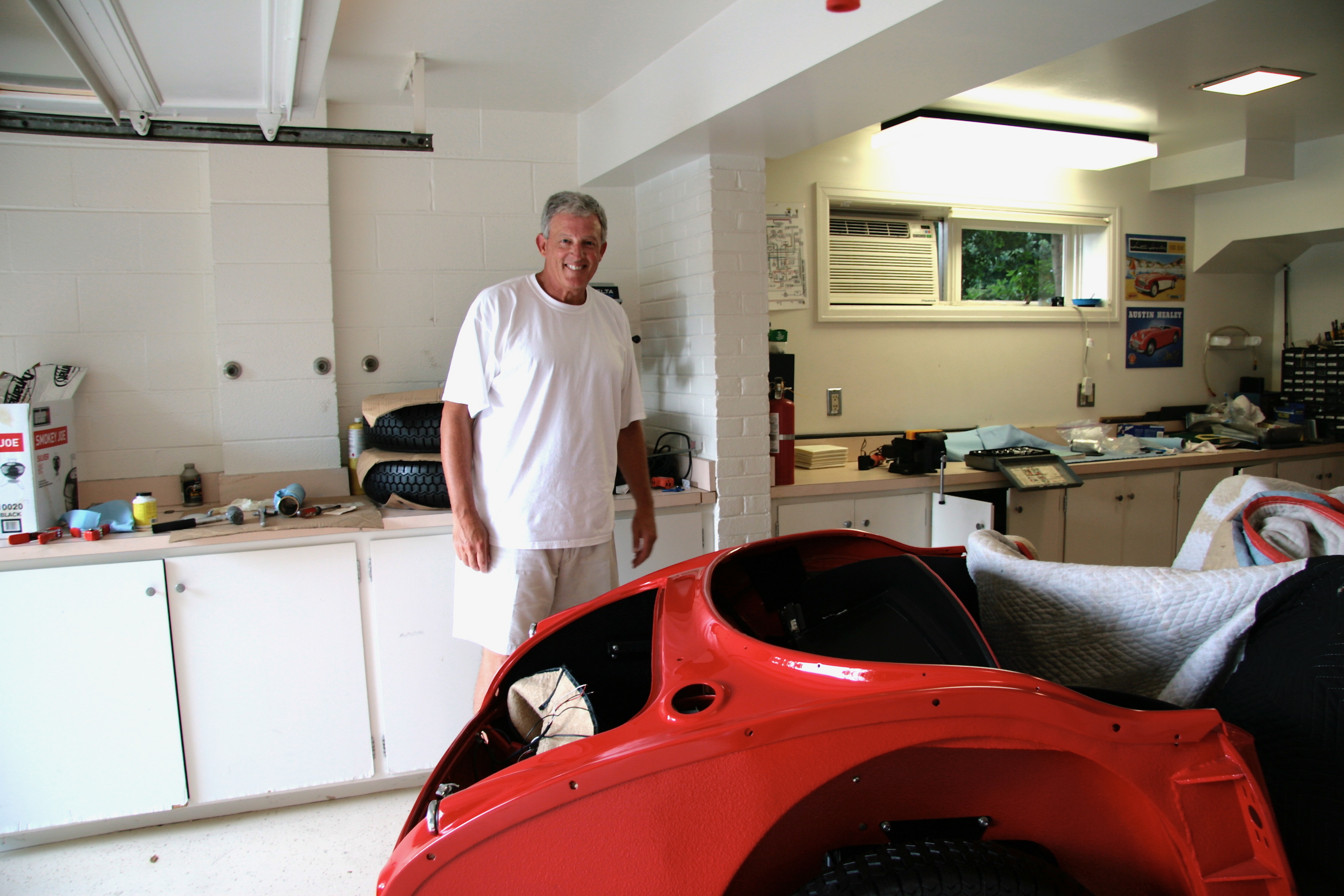
Jeremy Turner Begins His Work 

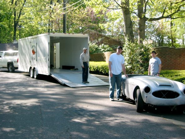
 We took the car to Jeremy in April, but he got stacked up during the summer months with the work of previous customers who wanted a few things done to ready their cars for shows of various types. Unfortunately, that meant pushing the BT7 off to the Fall.

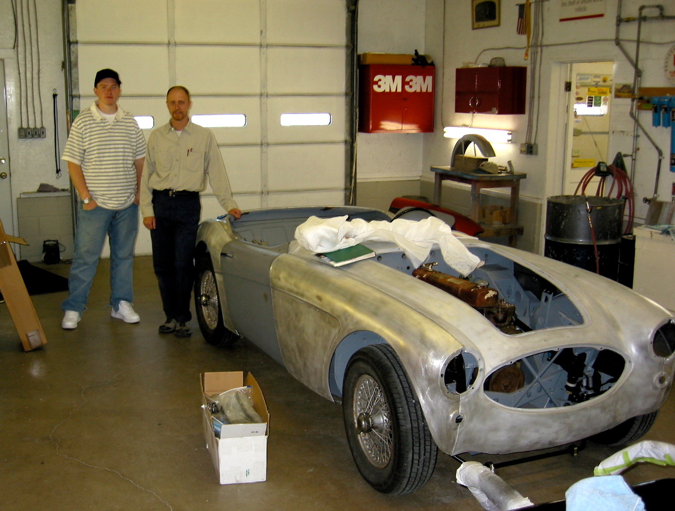
To Maple Hill Restorations 1

Maple Hill Restoration Arrival 1

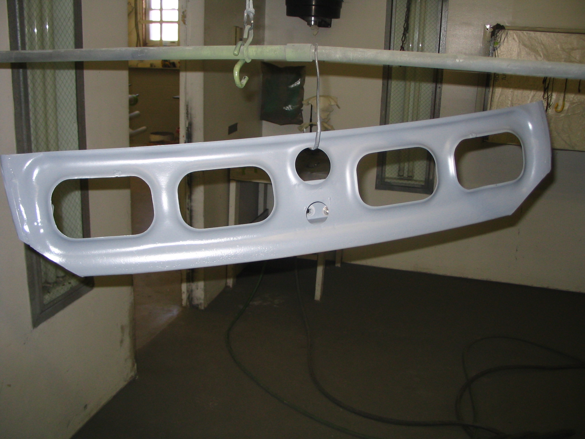
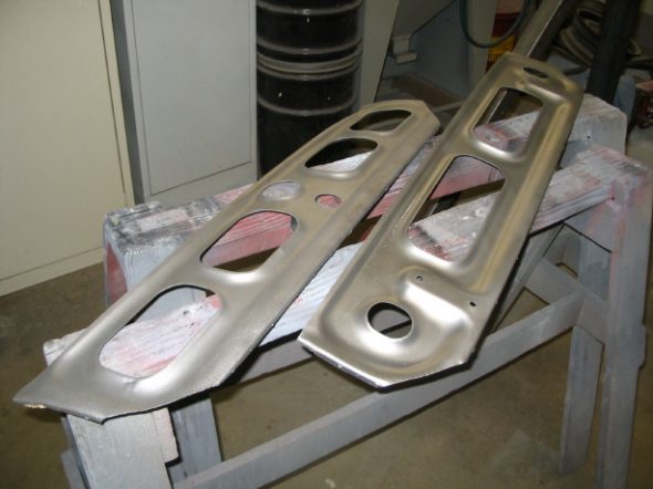
This week Jeremy got to work. First he media blasted and painted the seat backs and frames so that they could be sent to Heritage Upholstery for finish upholstery work. After I get Rick Kiser to build a new rear seat squab I will be ready to begin the waiting process for the interior work. I expect at least 2-3 months for that job.

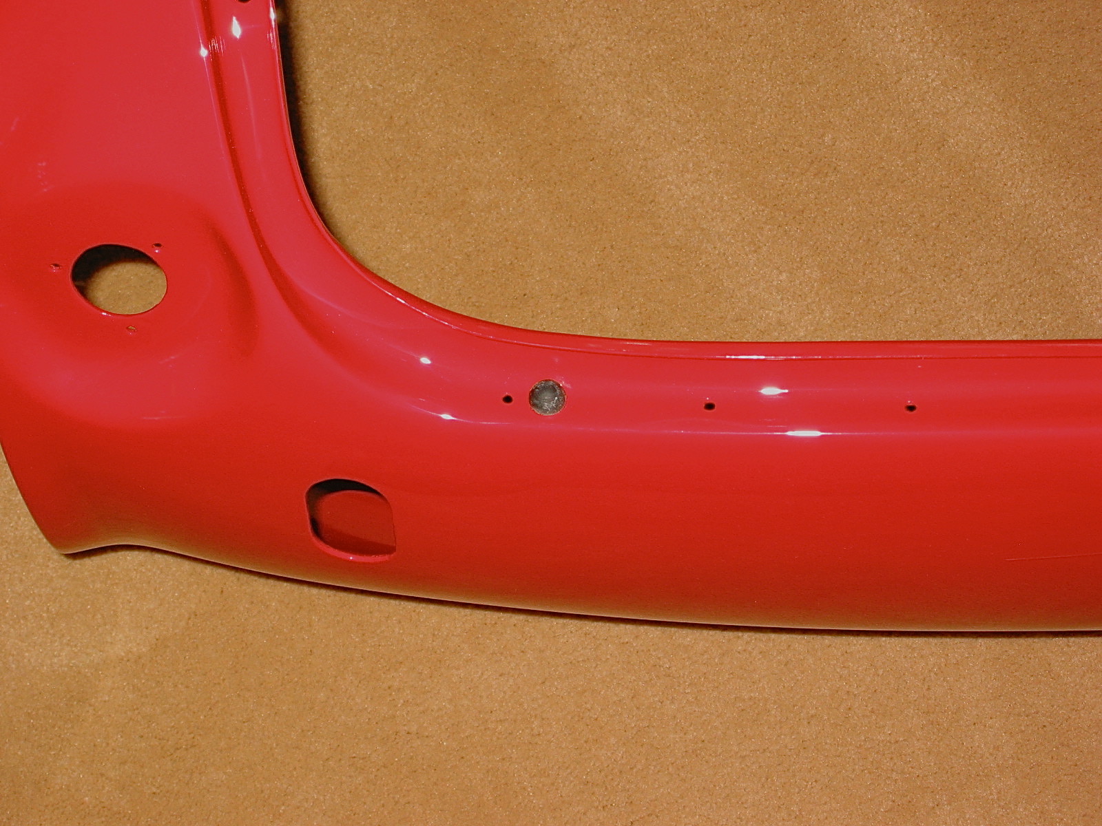
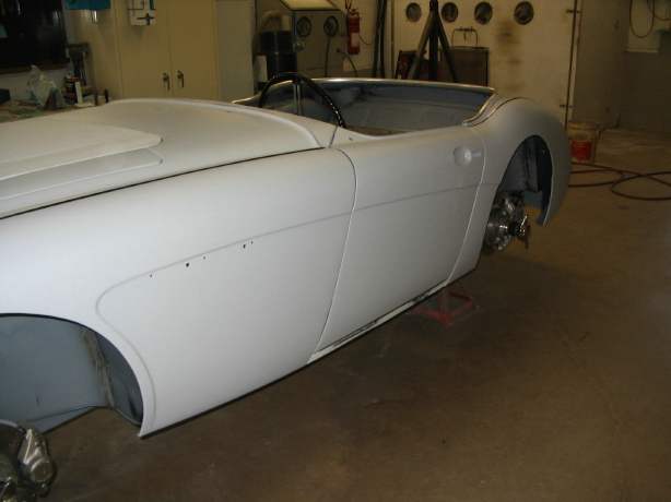
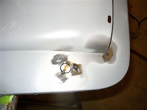
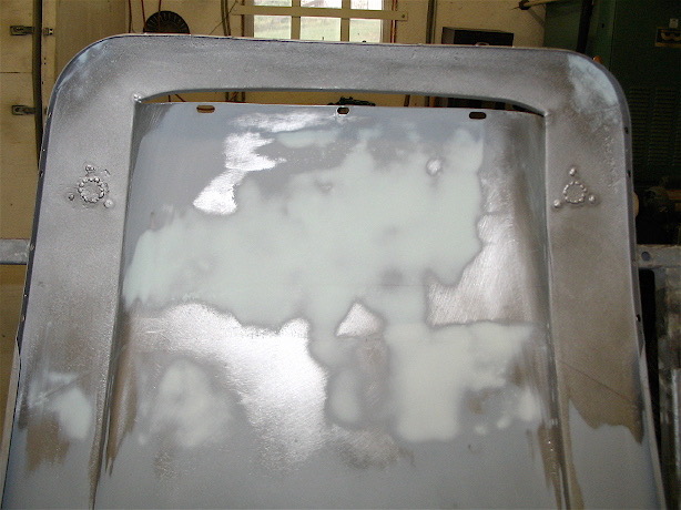
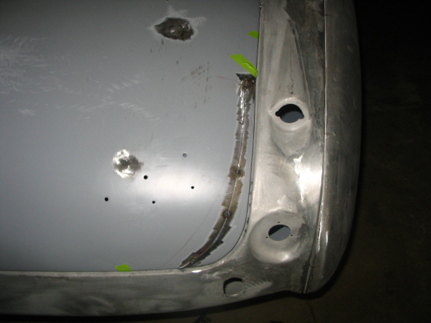
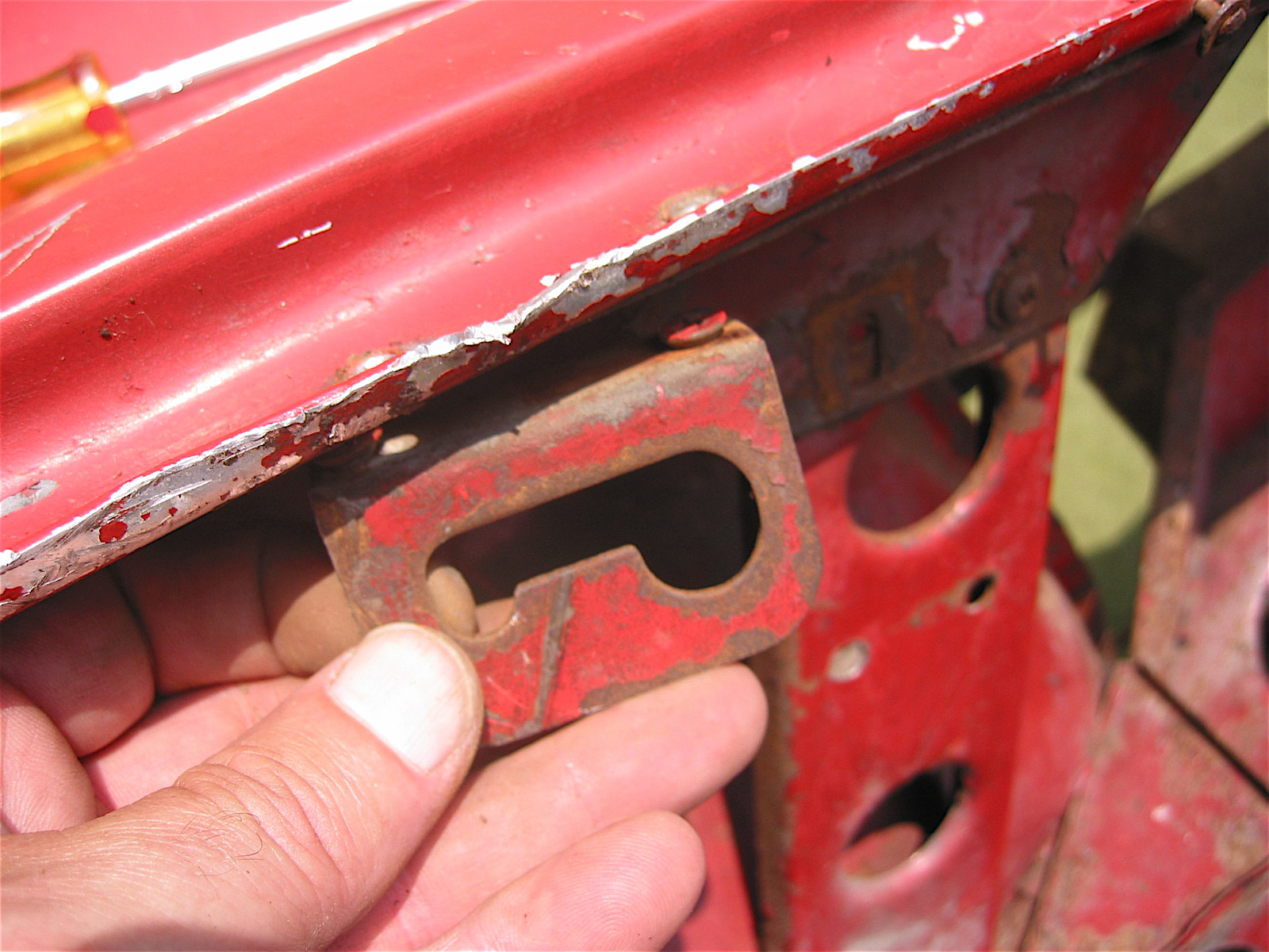
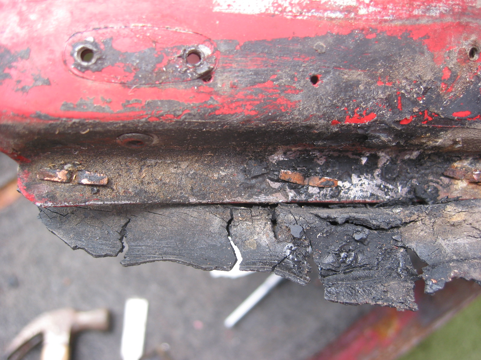
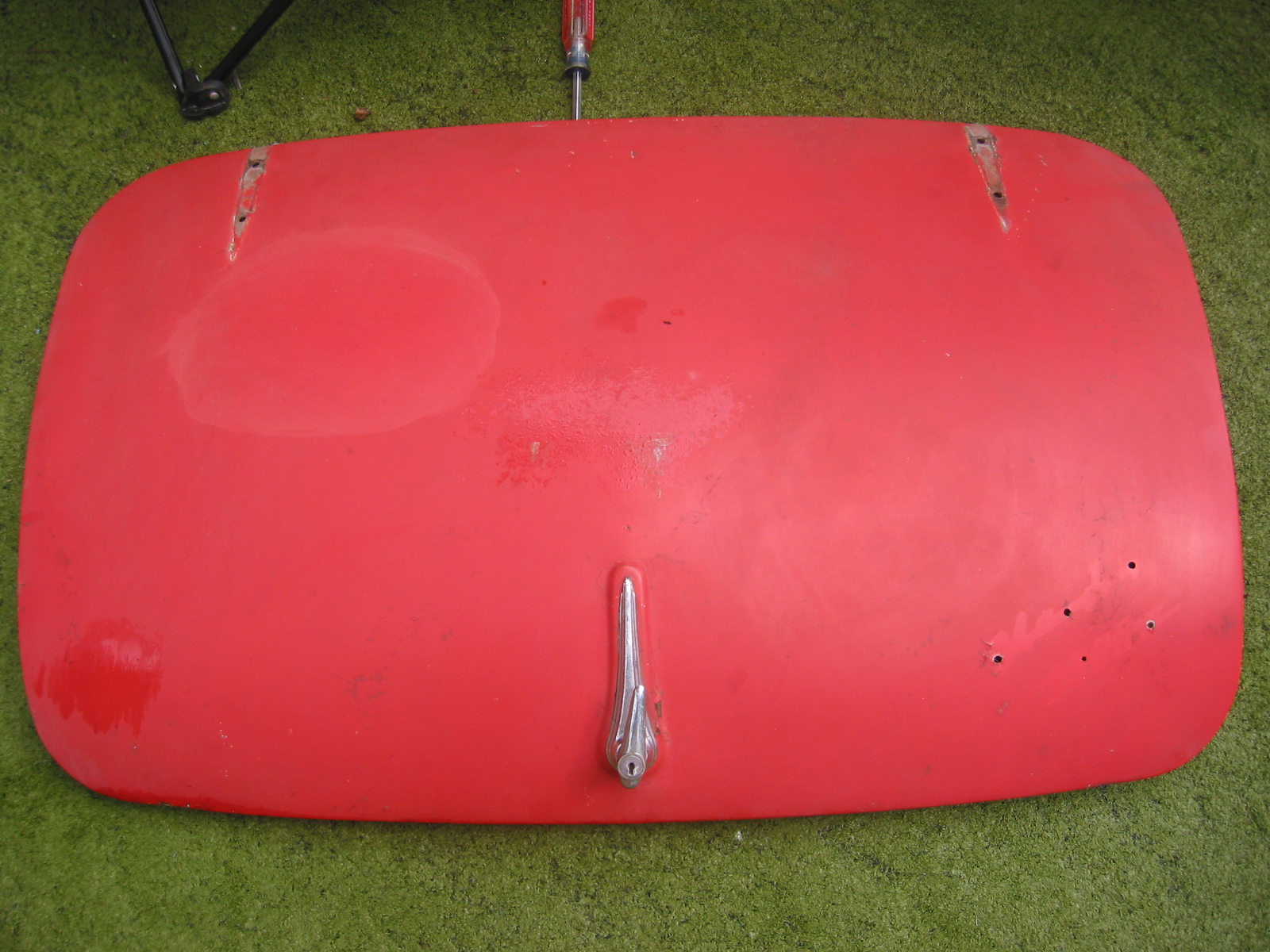
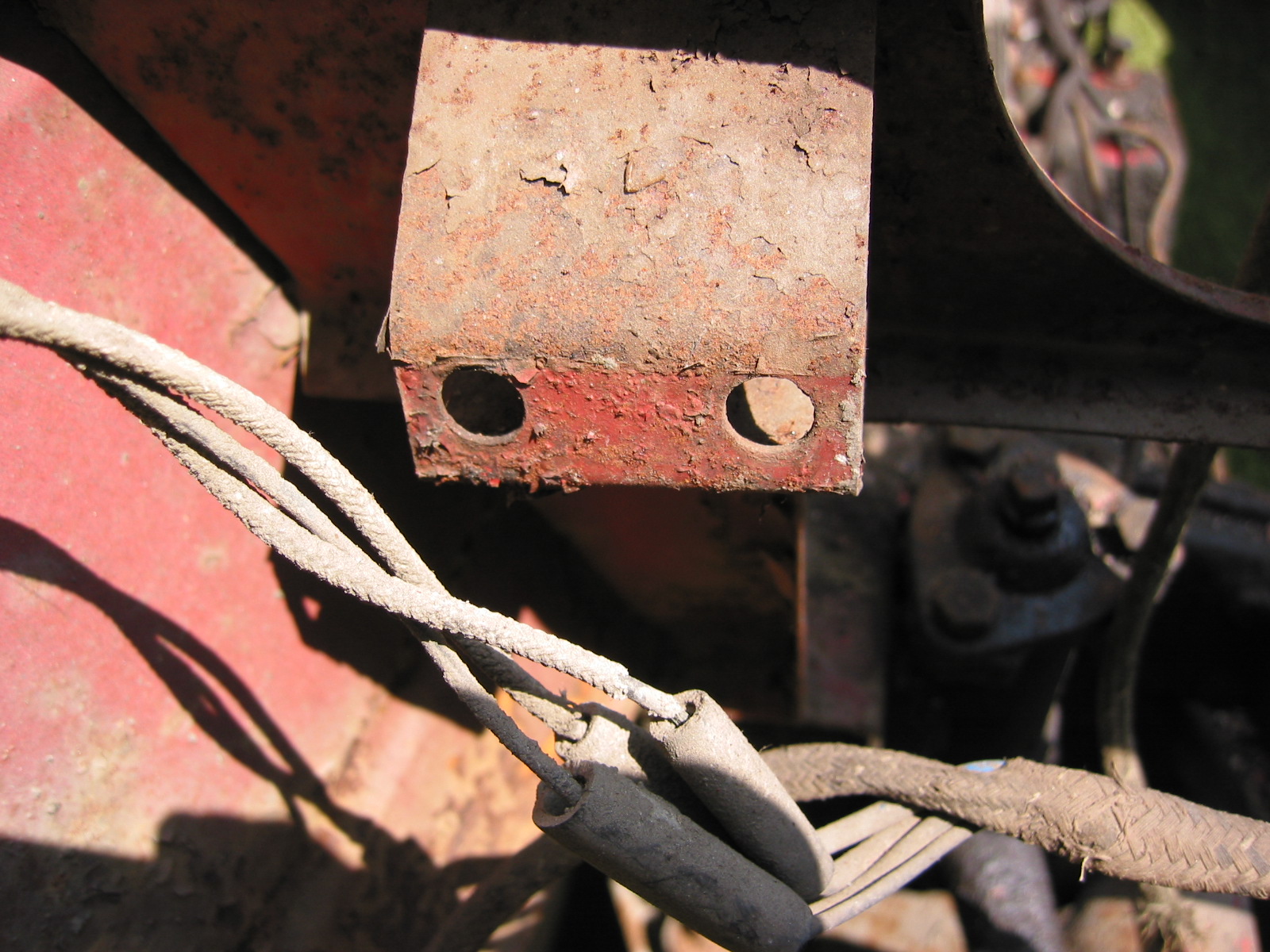
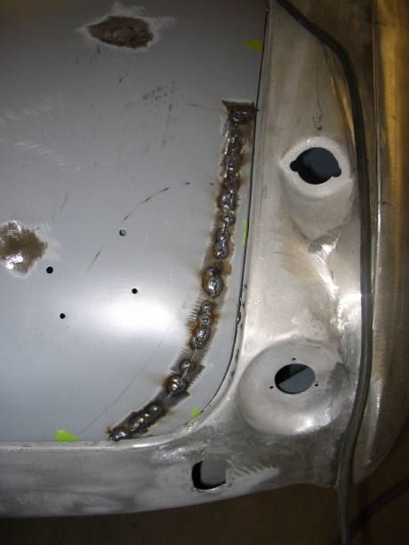
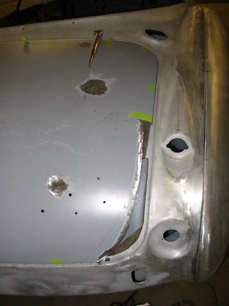
Jeremy began by fitting the doors and wings. Not as easy as it might have been since I am using new aluminum wings that don’t fit quite as nice as the originals, but the originals were consumed by rust. The bonnet had two holes punched in it for the installation of hood locks and we agreed that the holes needed to be filled. He cut the reinforcing frame off of the back of the bonnet to blast any rust from the skin, welded the holes closed and primed.

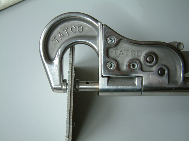
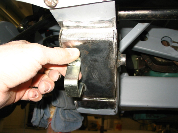
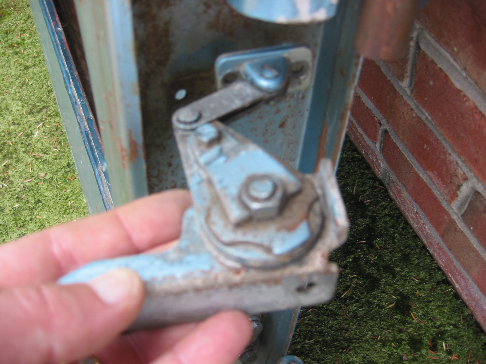
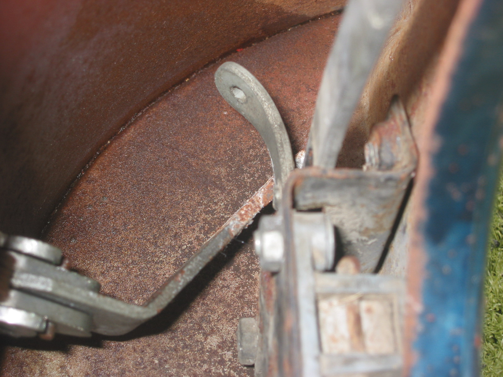
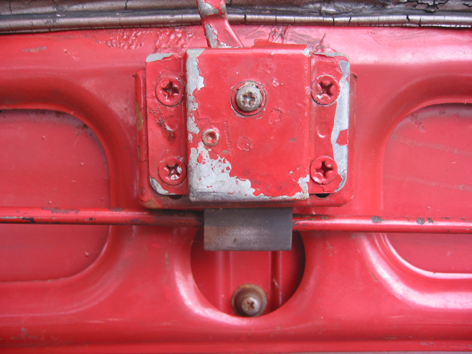
Latch brace removed_4

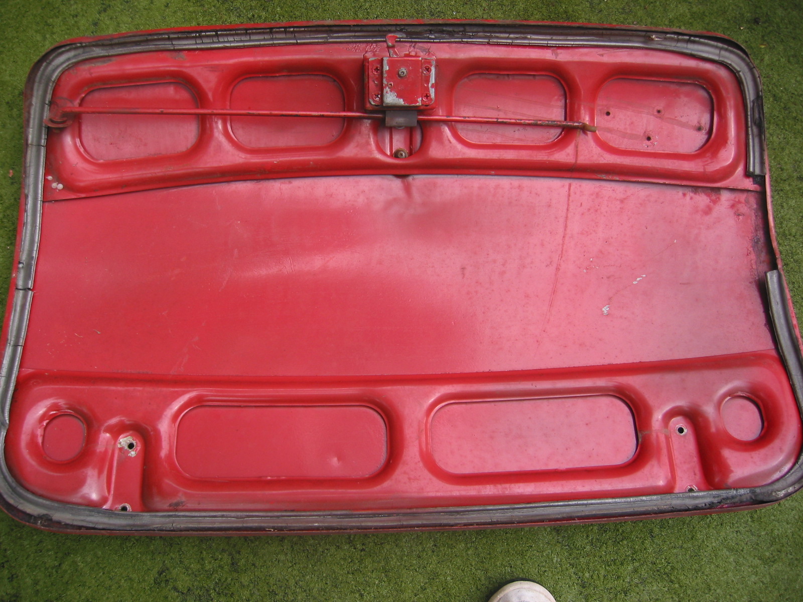
Underside of hood rust_7

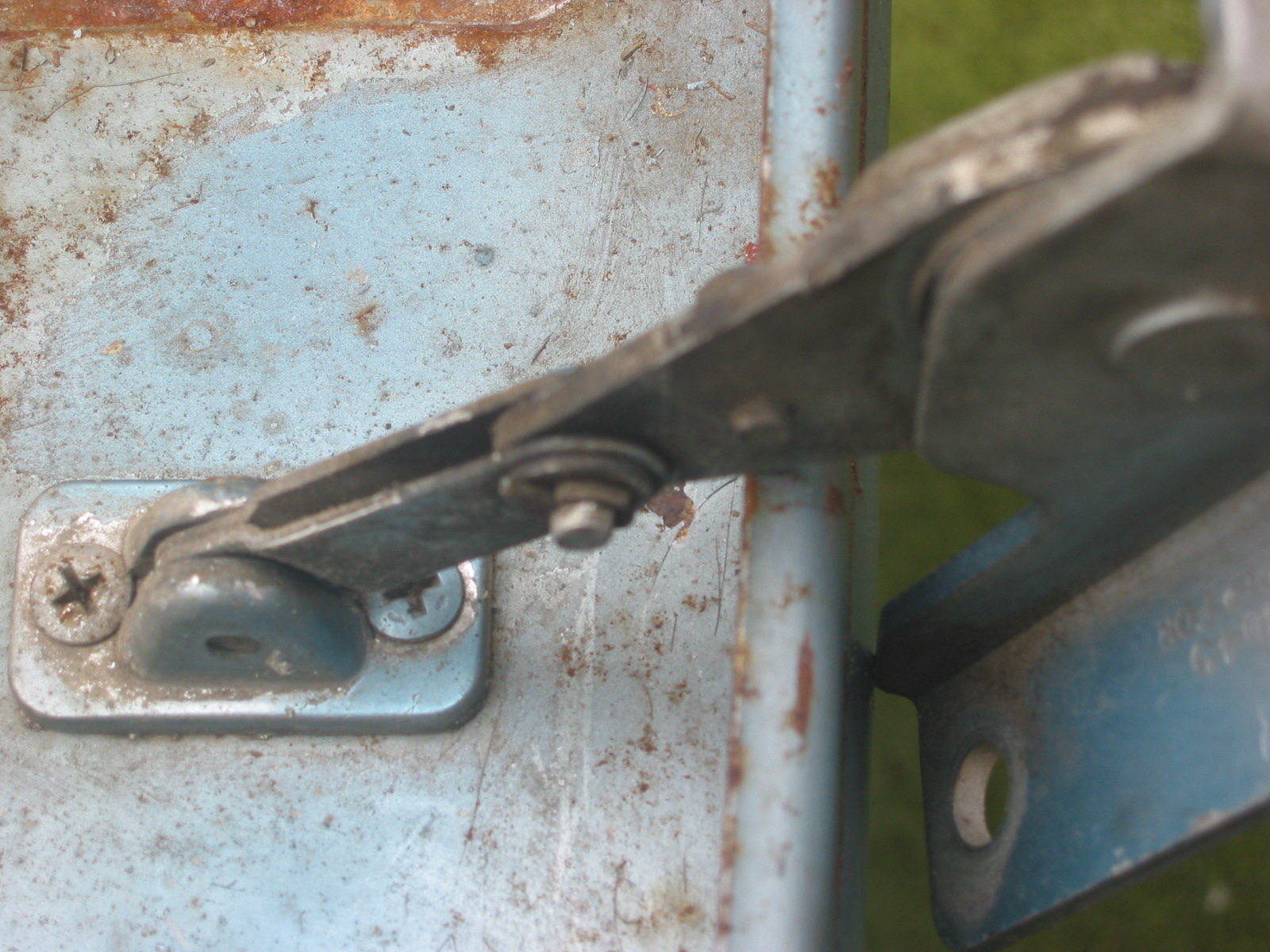
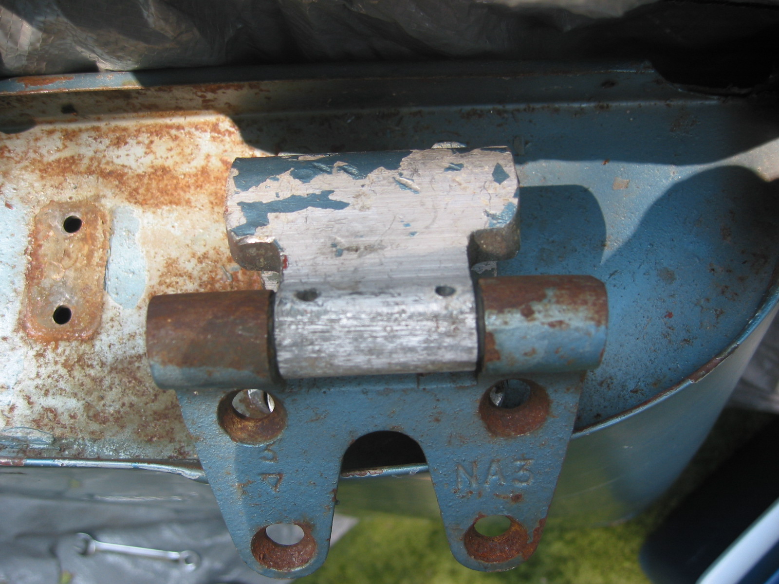
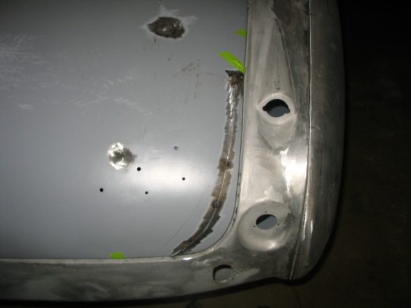
Outside of latch brace repaired and cleaned_6

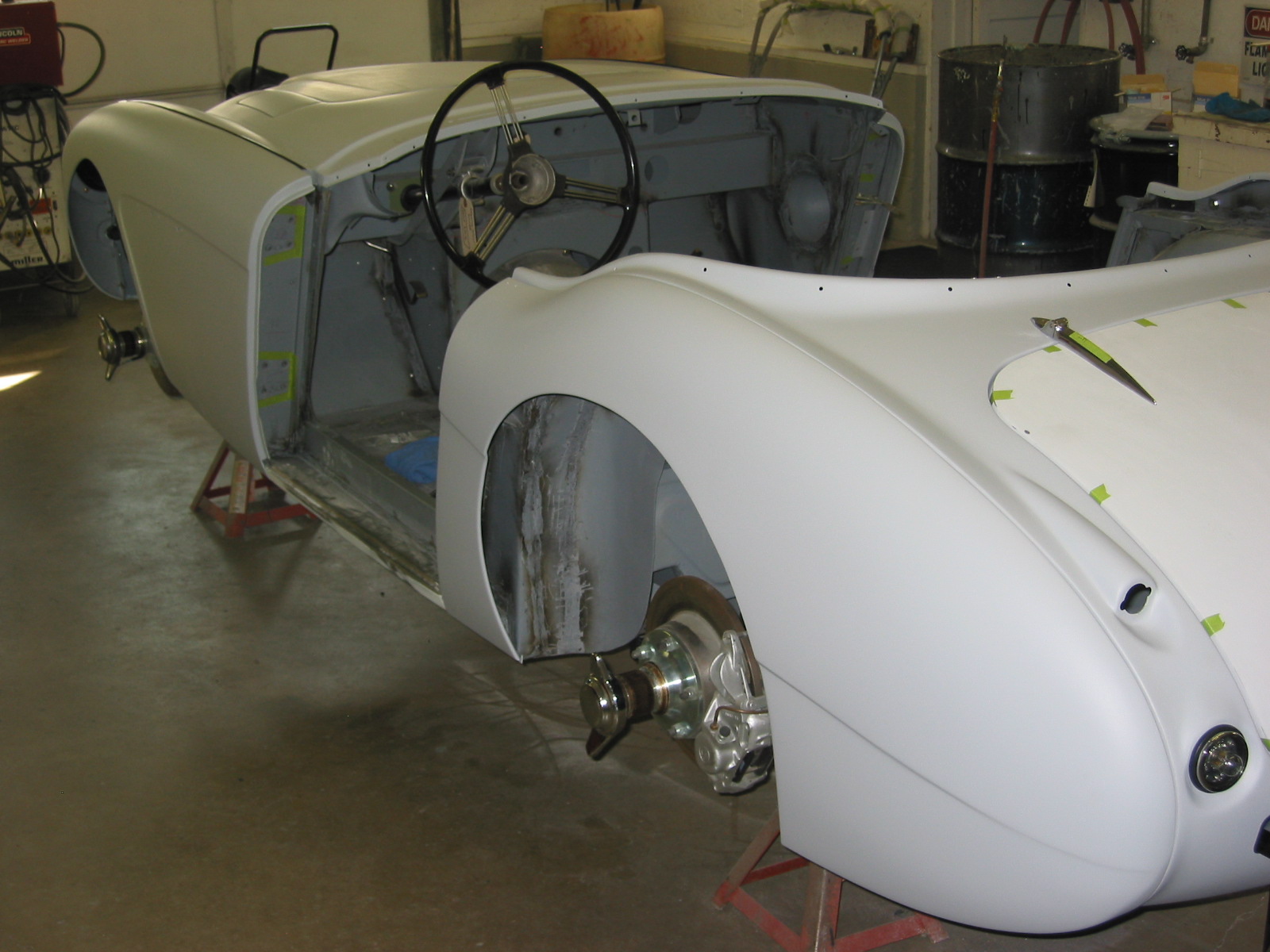
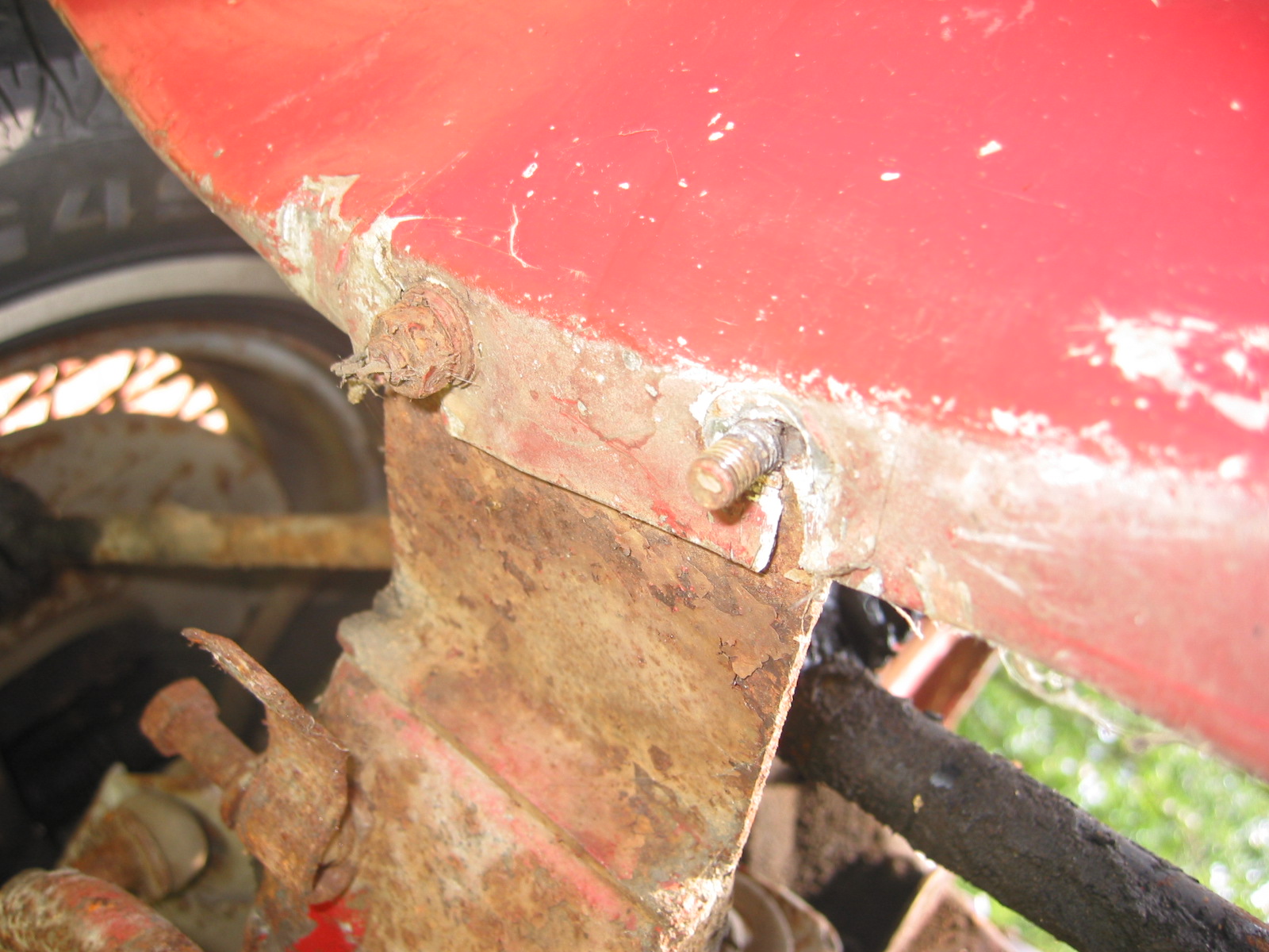
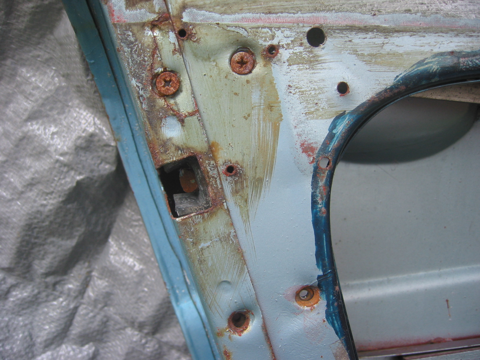
He also bent back the skin on the bottom of the doors to again get all the rust blasted out and primed. This will alleviate problems in the future. It is all a slow process, but it is what must be done to end up with the quality job I want!

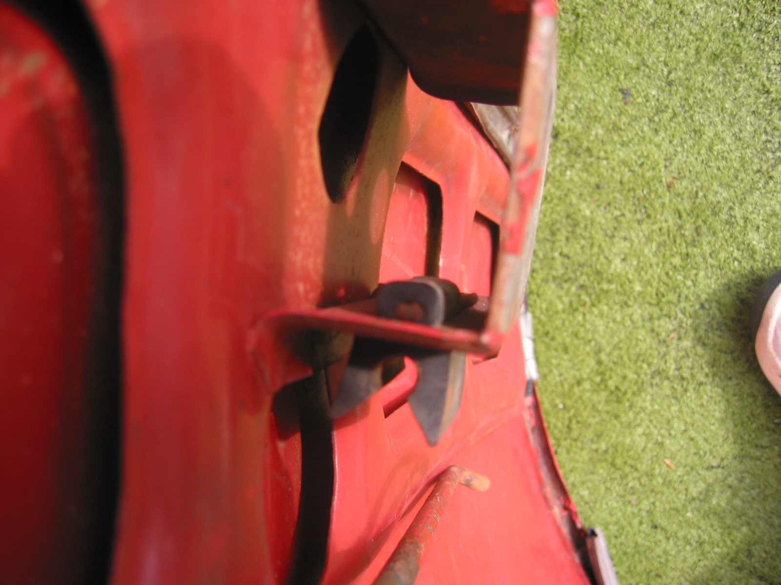
Rust exposed on bottom door edge_4

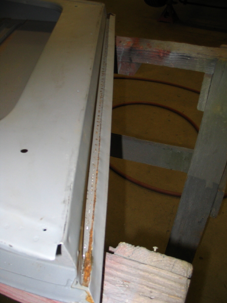
Door edge lip pulled out to expose rust_3

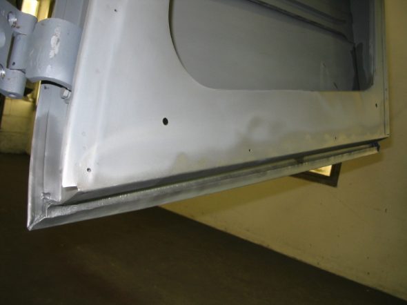
Door edge glassbeaded to remove rust_2

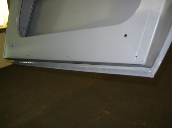
Door edge epoxy primed_1

I received the windscreen frame from Custom Chrome Plating in PA. It was a beautiful chrome replating job. It should have been for $500.00 for four frame pieces! I took it and glass and hardware to Village Auto Center in Harrisonburg for assembly. I am nervous about their care, but I expect everything will come back fine.

September 20, 2005

The windshield came back and was nicely assembled except the corners don’t meet as tightly as they need to to prevent leakage. I will work on that later before final assembly. I put the pillars on the frame and will take it to Jeremy for fitting to the body.

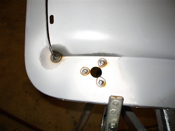
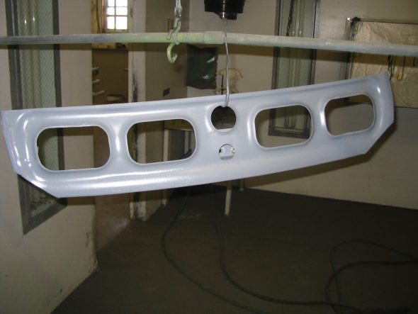
Jeremy sent some new images of his latest work that focused on cleaning up the bonnet, fixing a dent and filling the lock holes.

Rear hood brace removed_4

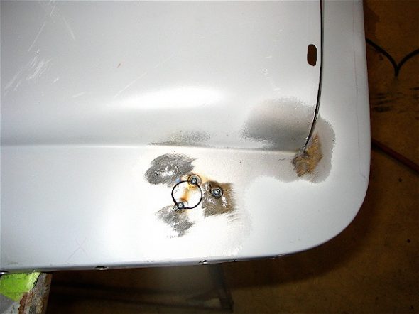
Hood pin holes being welded_6

Screw holes welded up_2

Right hand hole welded up_1

Left hand hole shut up_3

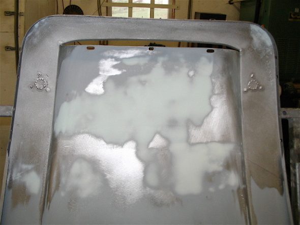
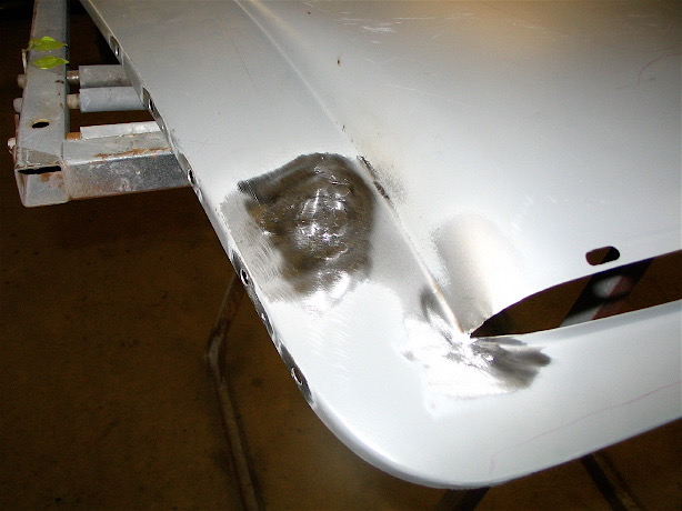
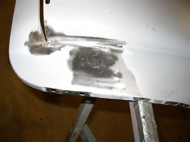
Rust cleaned from underside of hood and dents removed._3

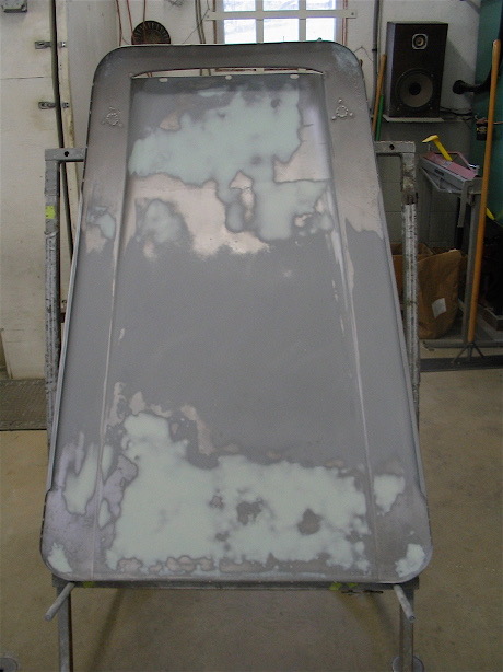
Body work done on underside of hood in areas that would be hard to get to when the braces are welded into place

Rear hood brace removed_4

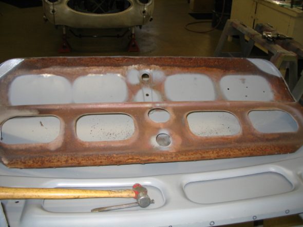
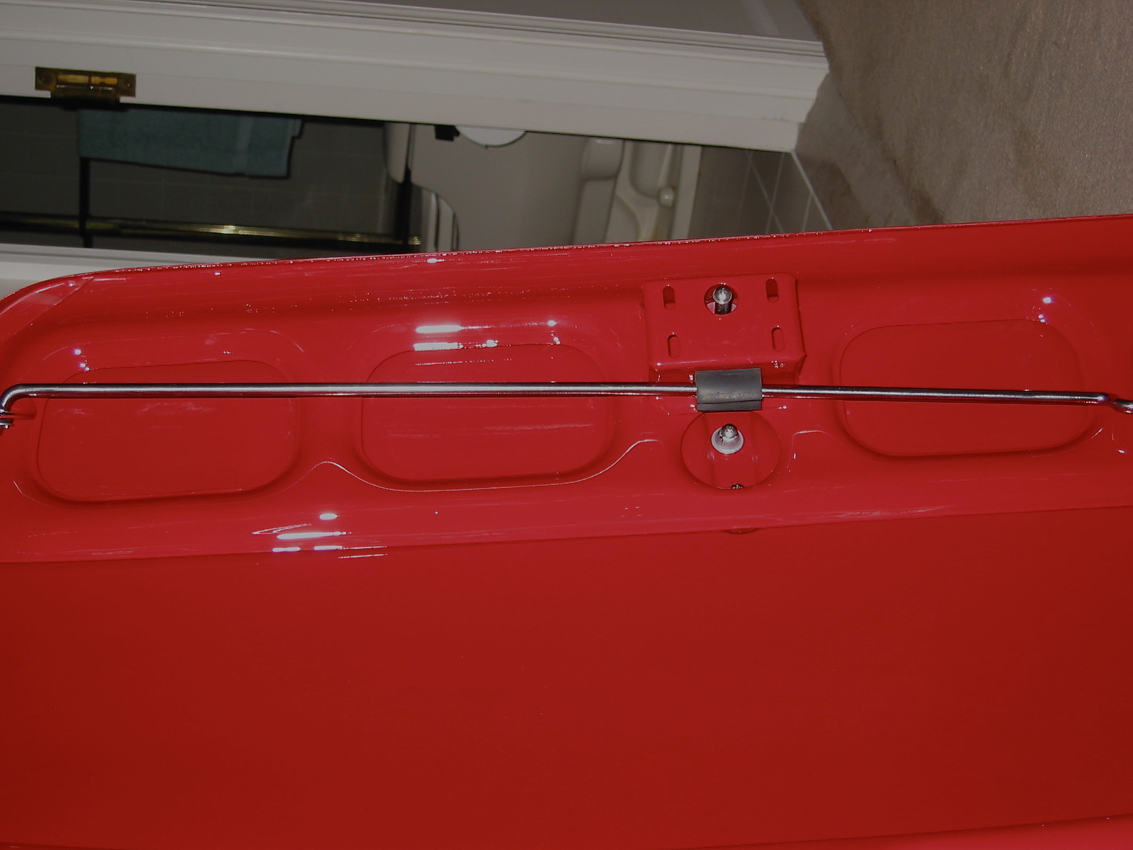
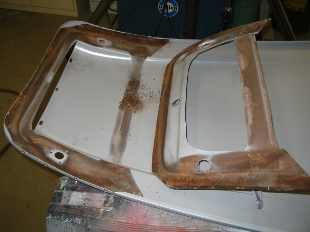
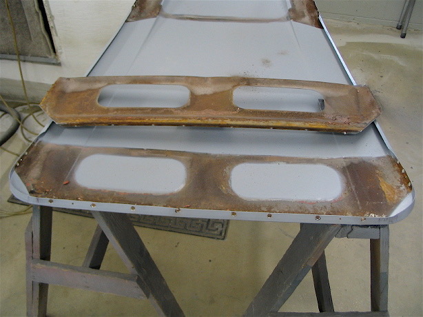
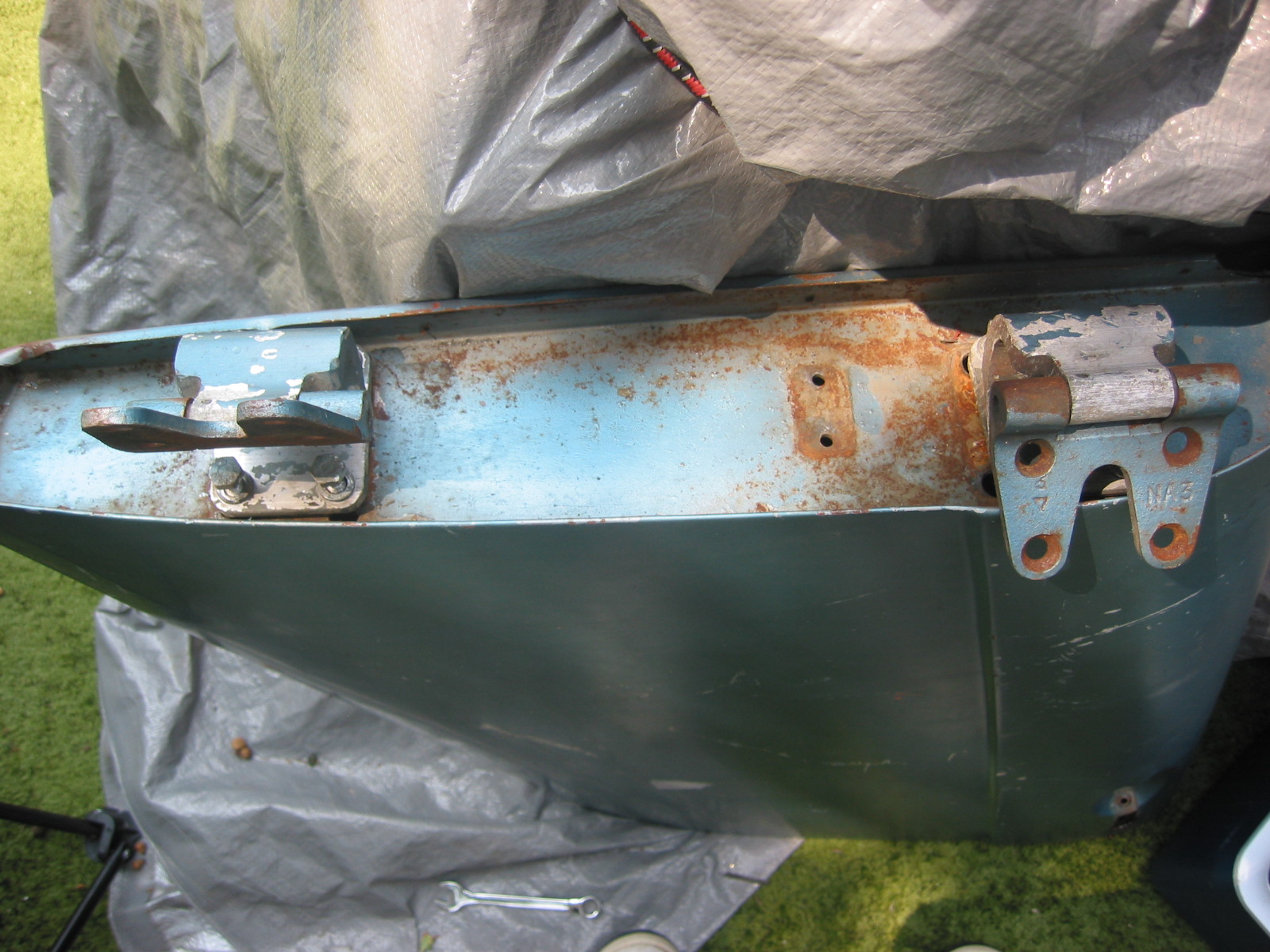
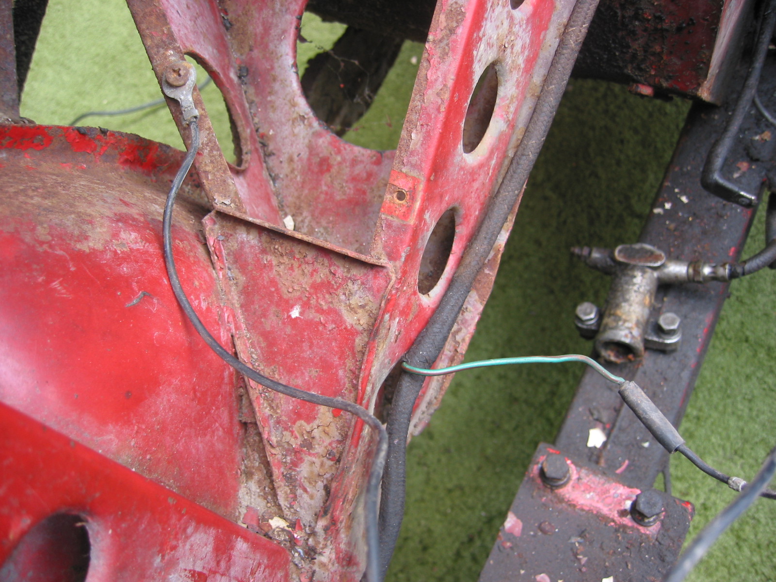
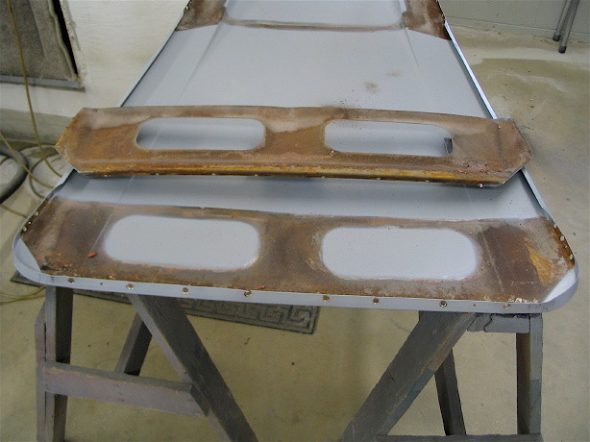
Trunk brace removed_6

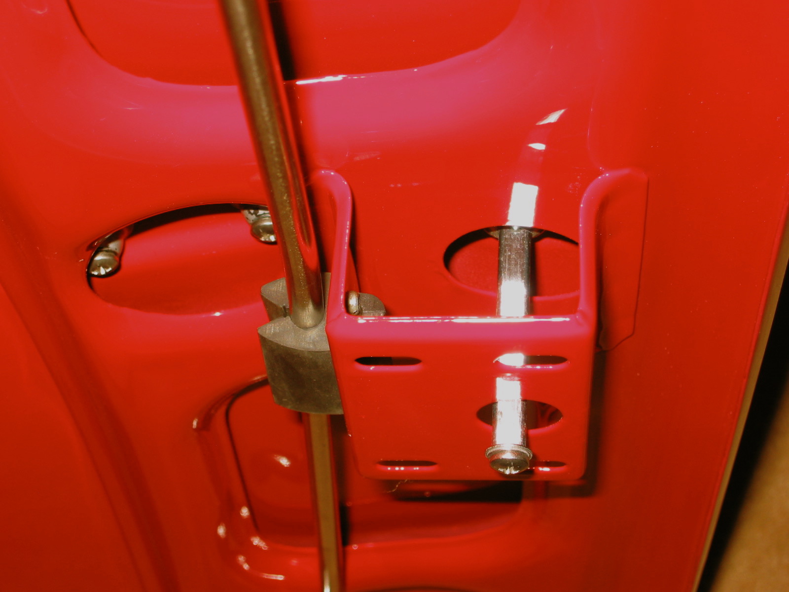
Trunk braces cleaned_8

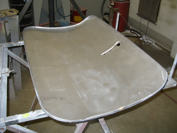
Underside trunk lid cleaned

December 10, 2005

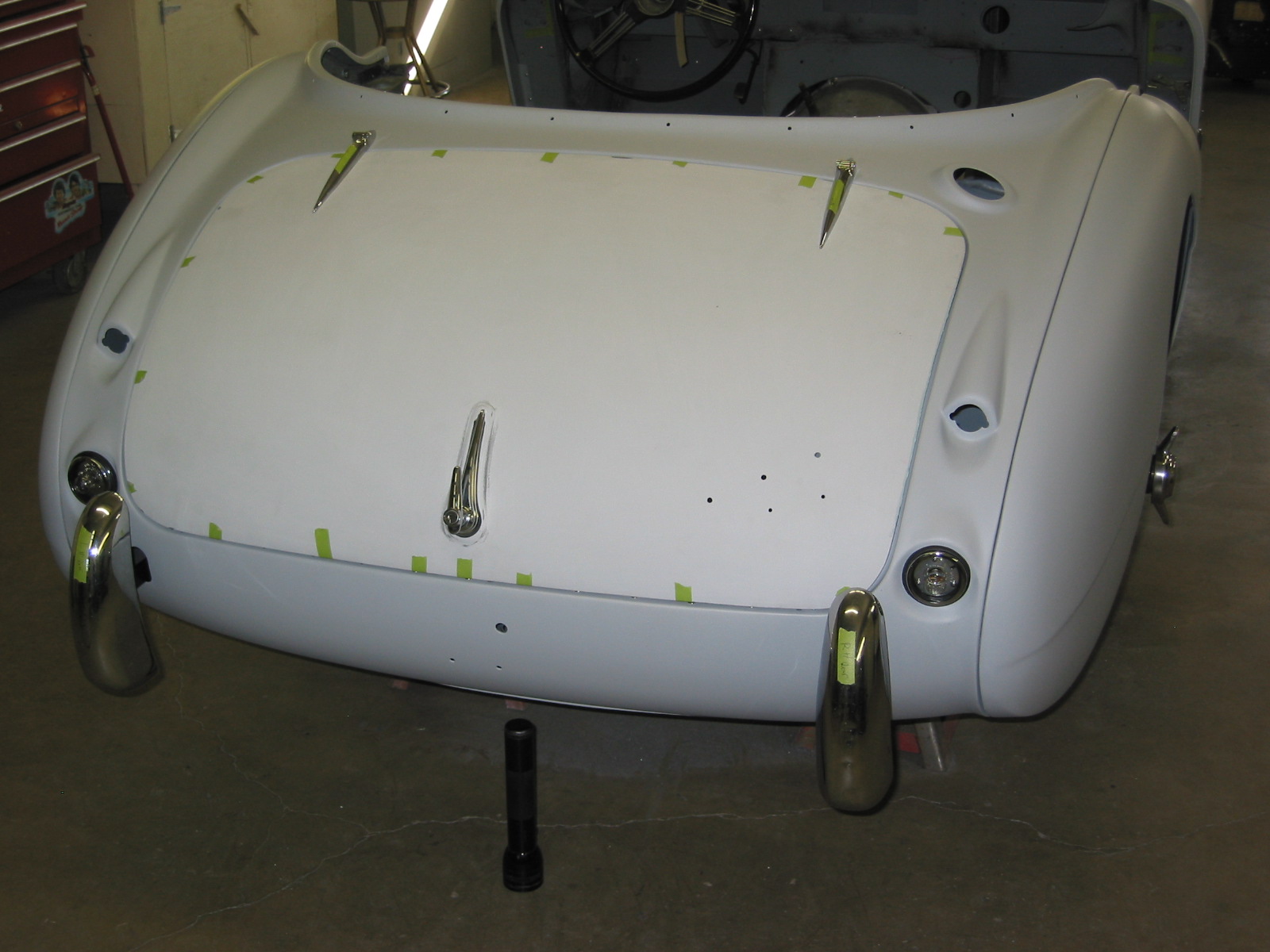
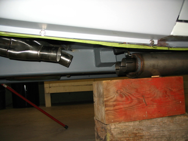
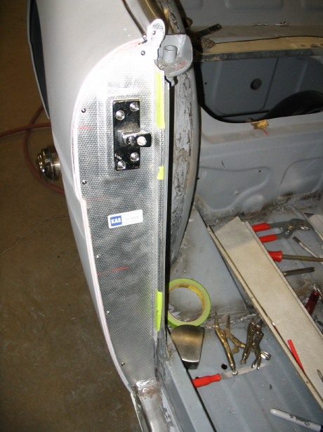
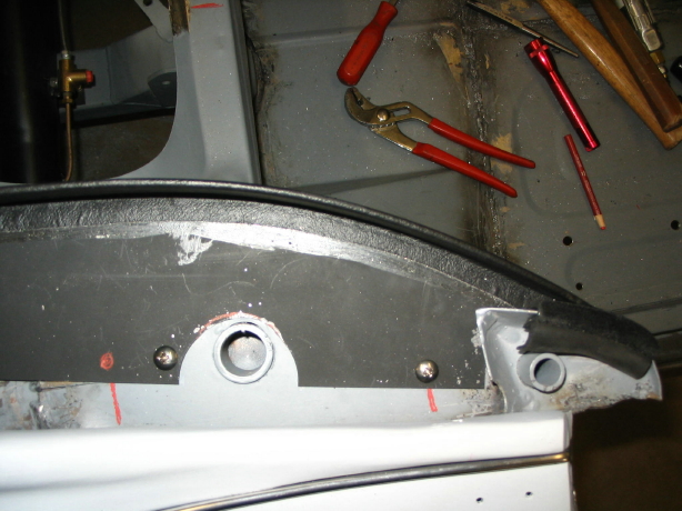
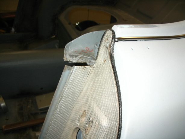
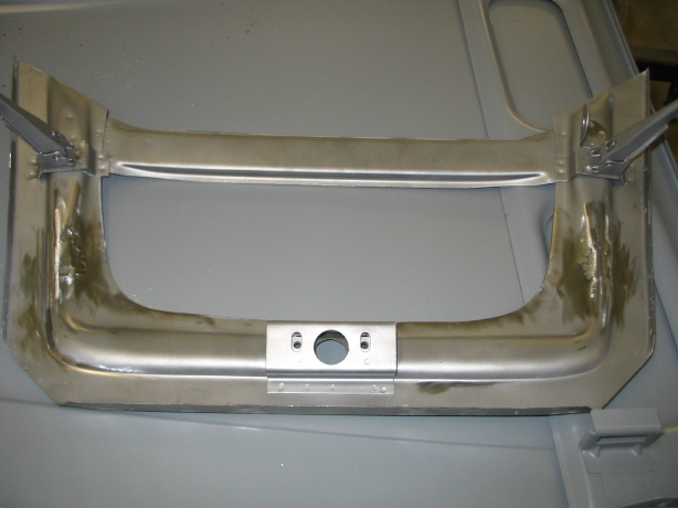
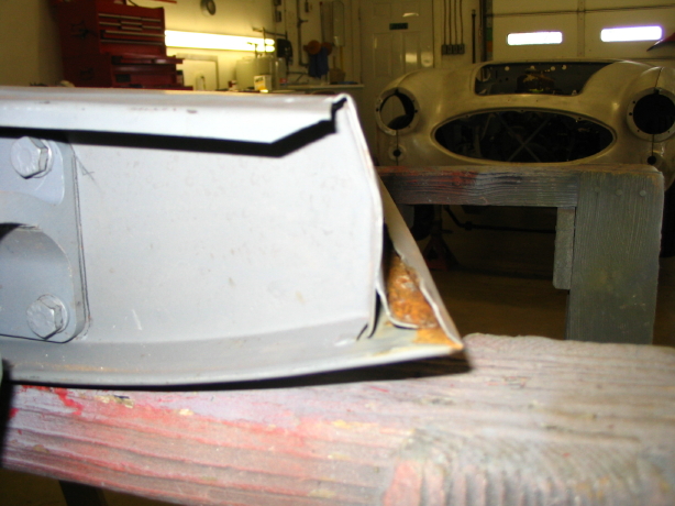
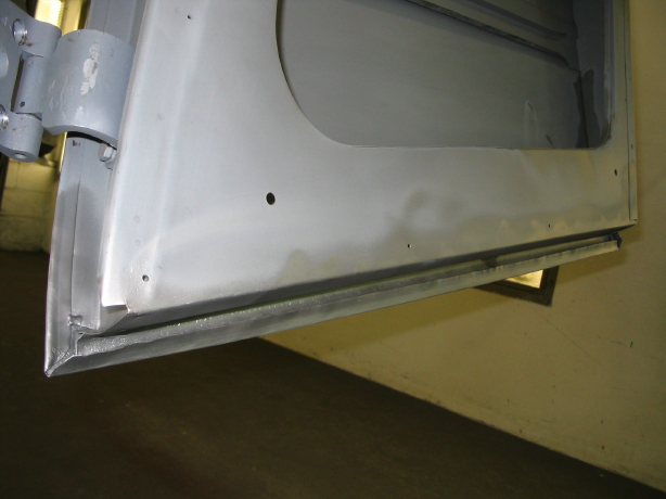
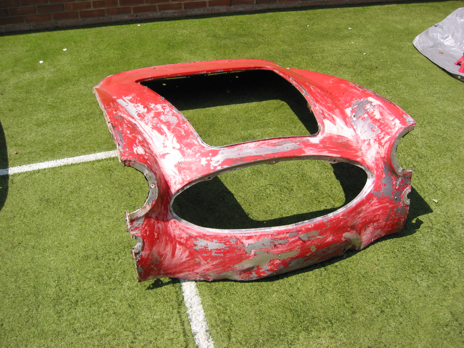
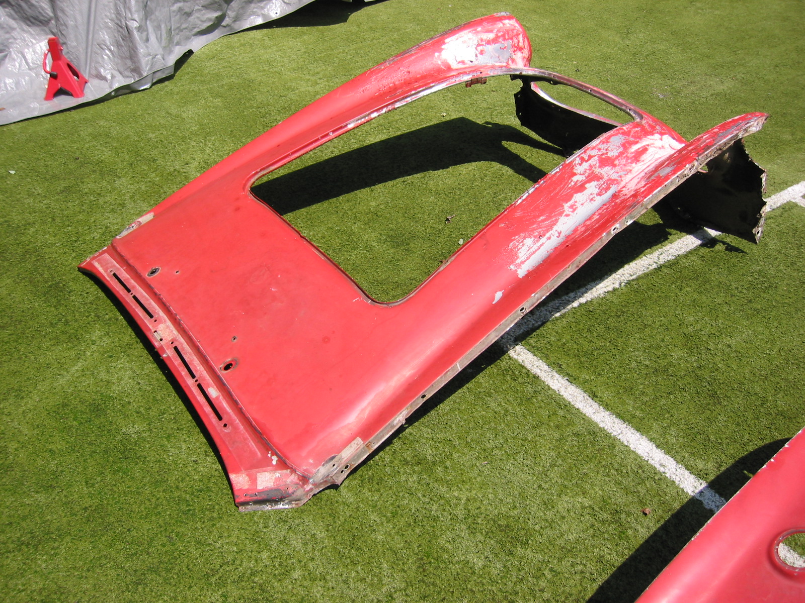
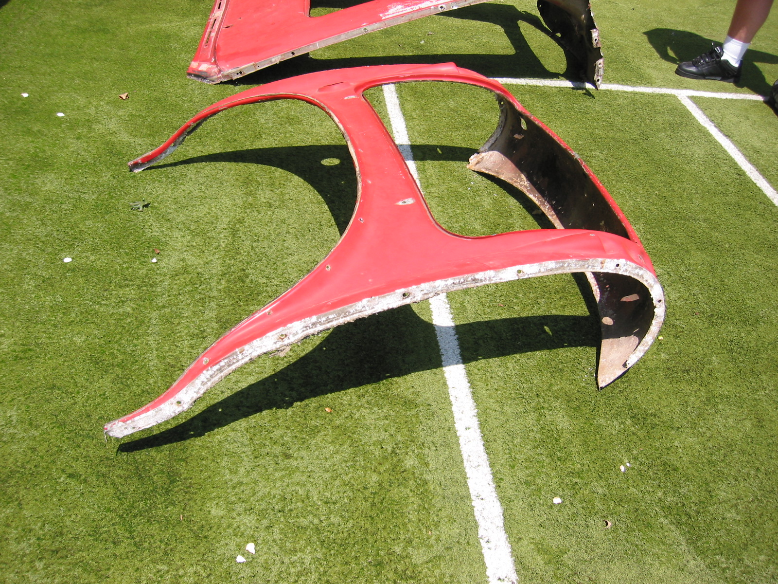
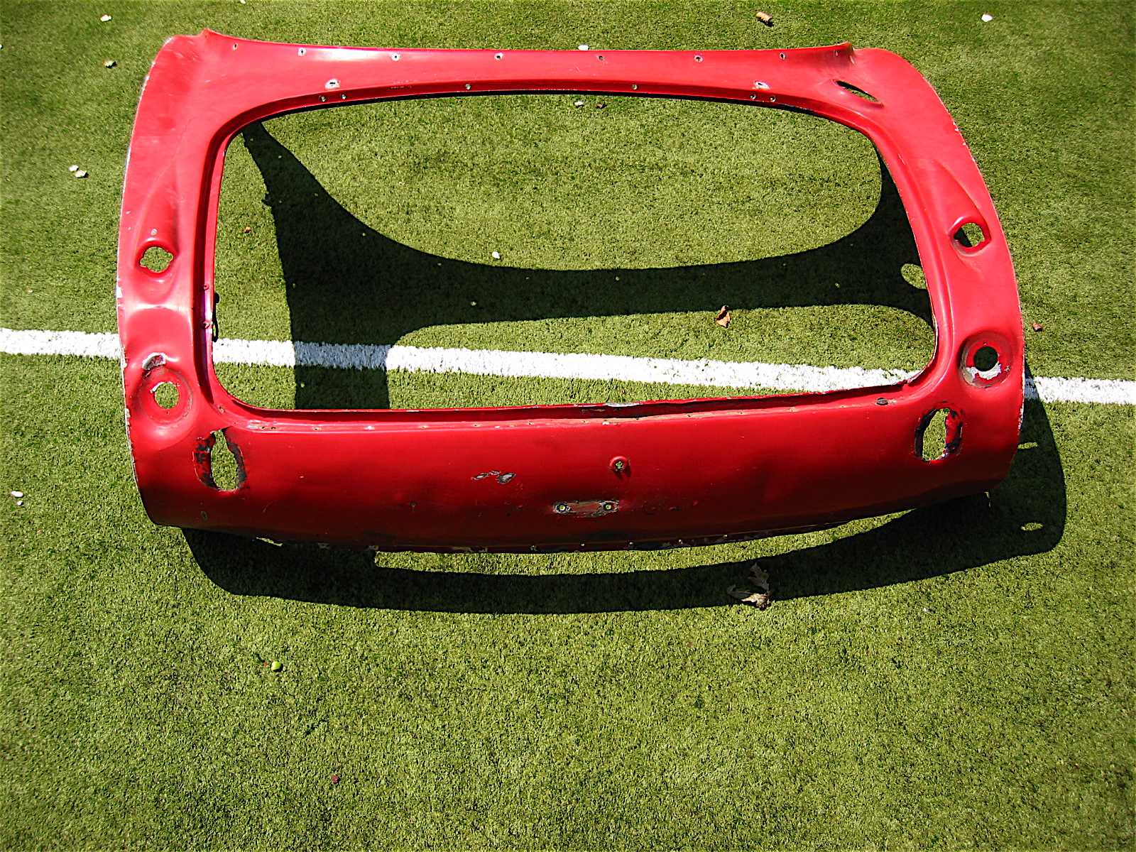
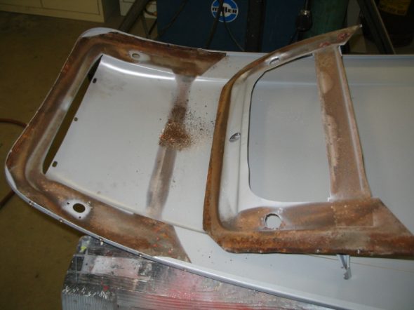
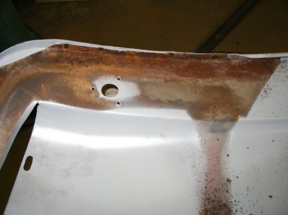
I have been disappointed that after a good start in September, Jeremy began working on other projects and didn’t make much progress with the Healey. He got back to work after Thanksgiving and forwarded the following photos of work done on the boot lid. It was badly deformed, cracked on the top side edges and didn’t fit the shroud particulalry well. I was pleased to see his skill with cutting and welding. Things are looking up!

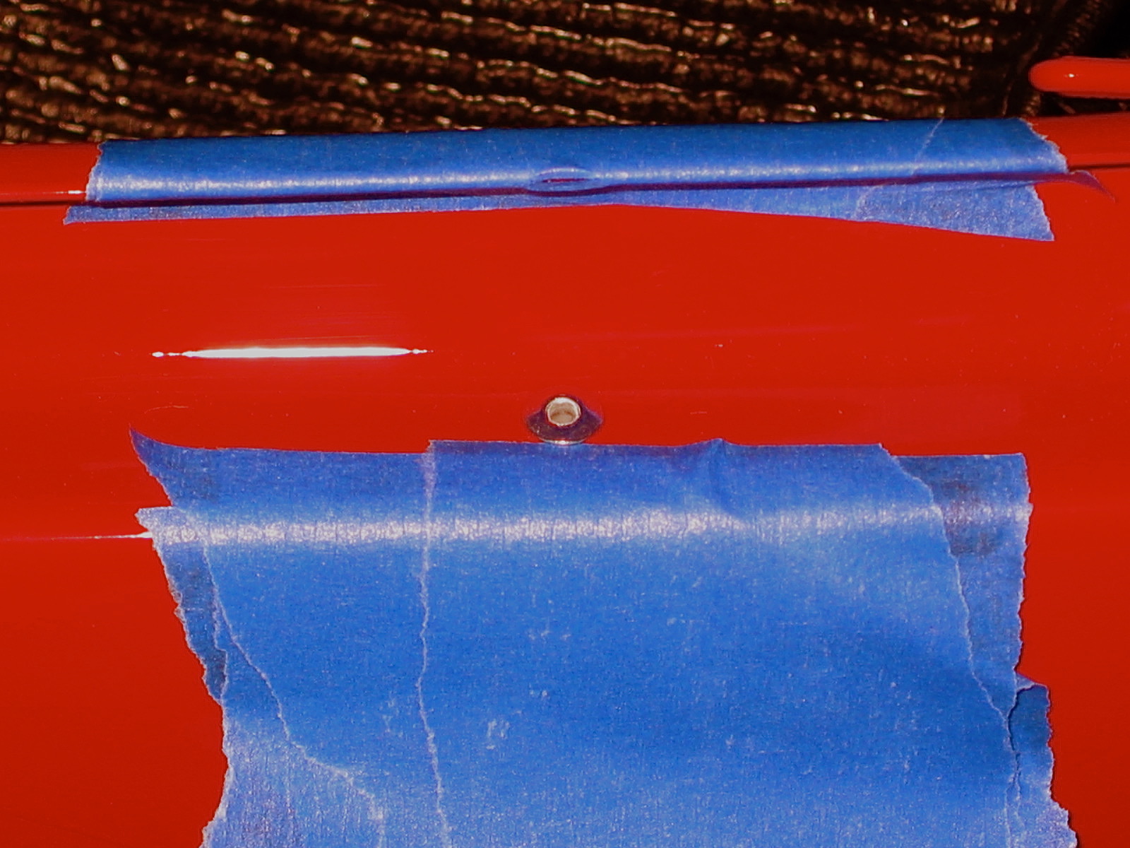
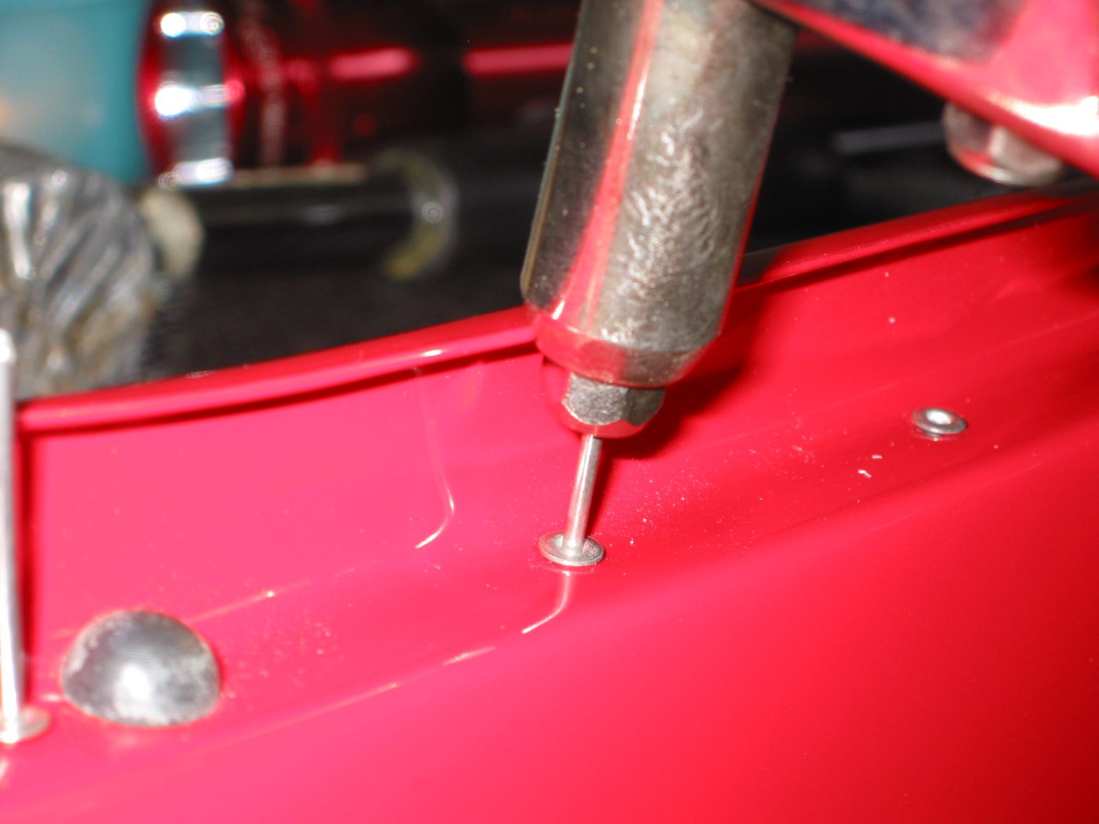
adjusting LH trunk gap_4

adjusting RH trunk gap_5

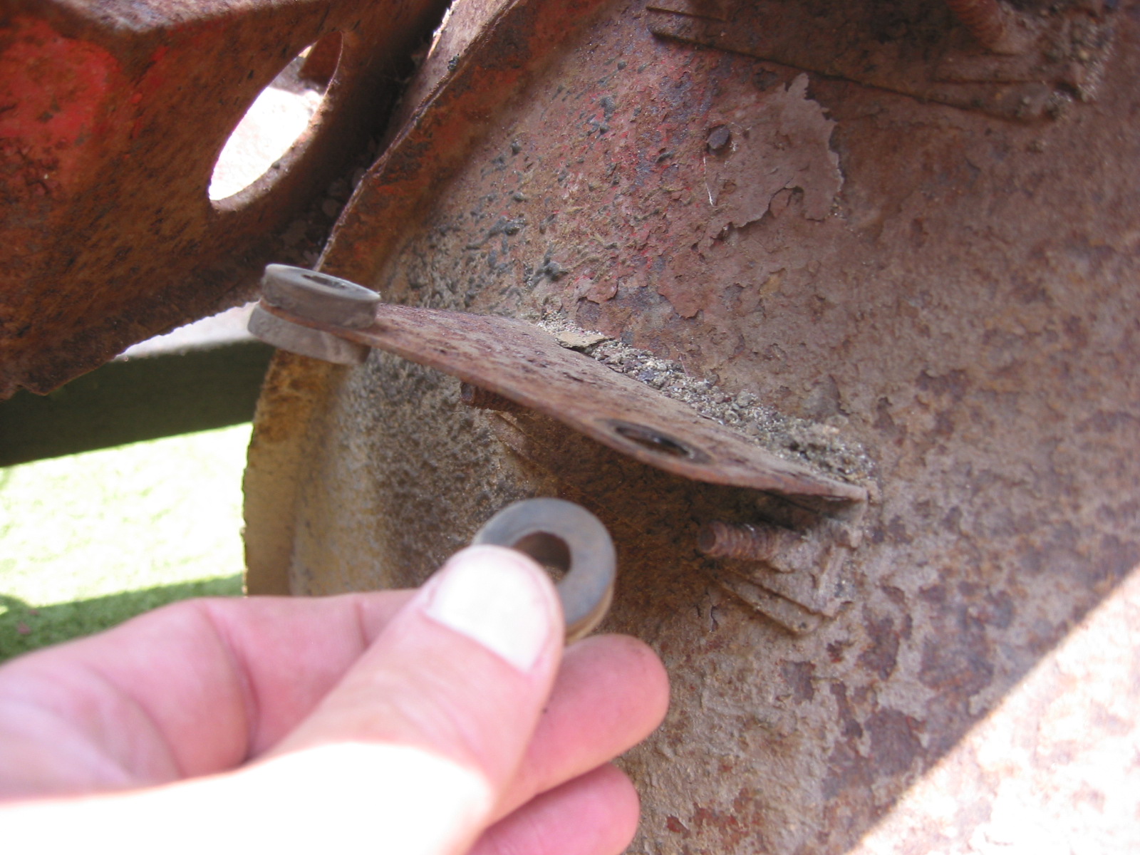
new trunk edge to adjust gap

trunk edge removed

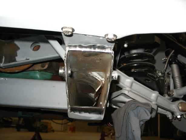
epoxy primed latch brace

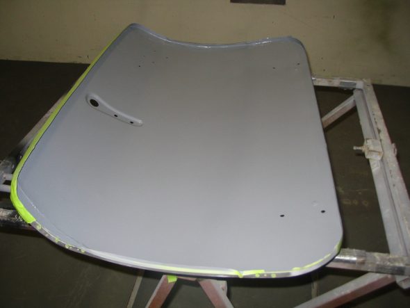
underside epoxy primed

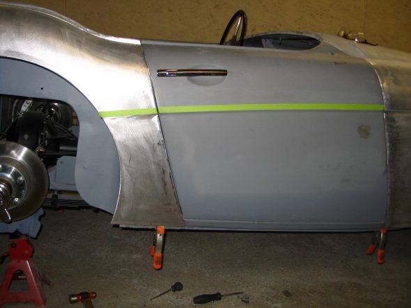
aligning the door and quarter gap

February 19, 2006

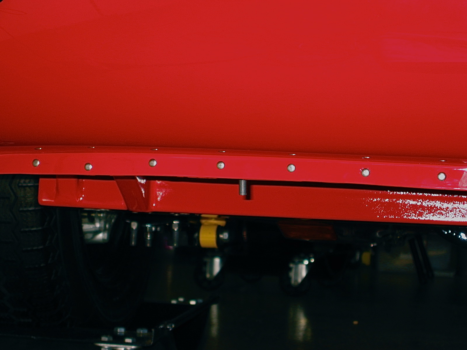
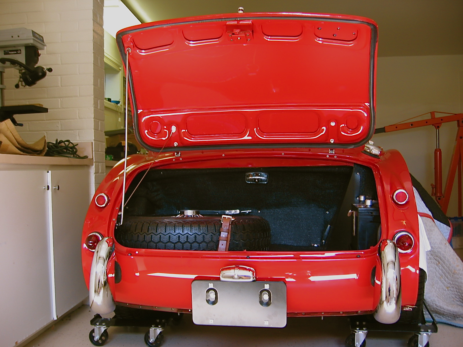
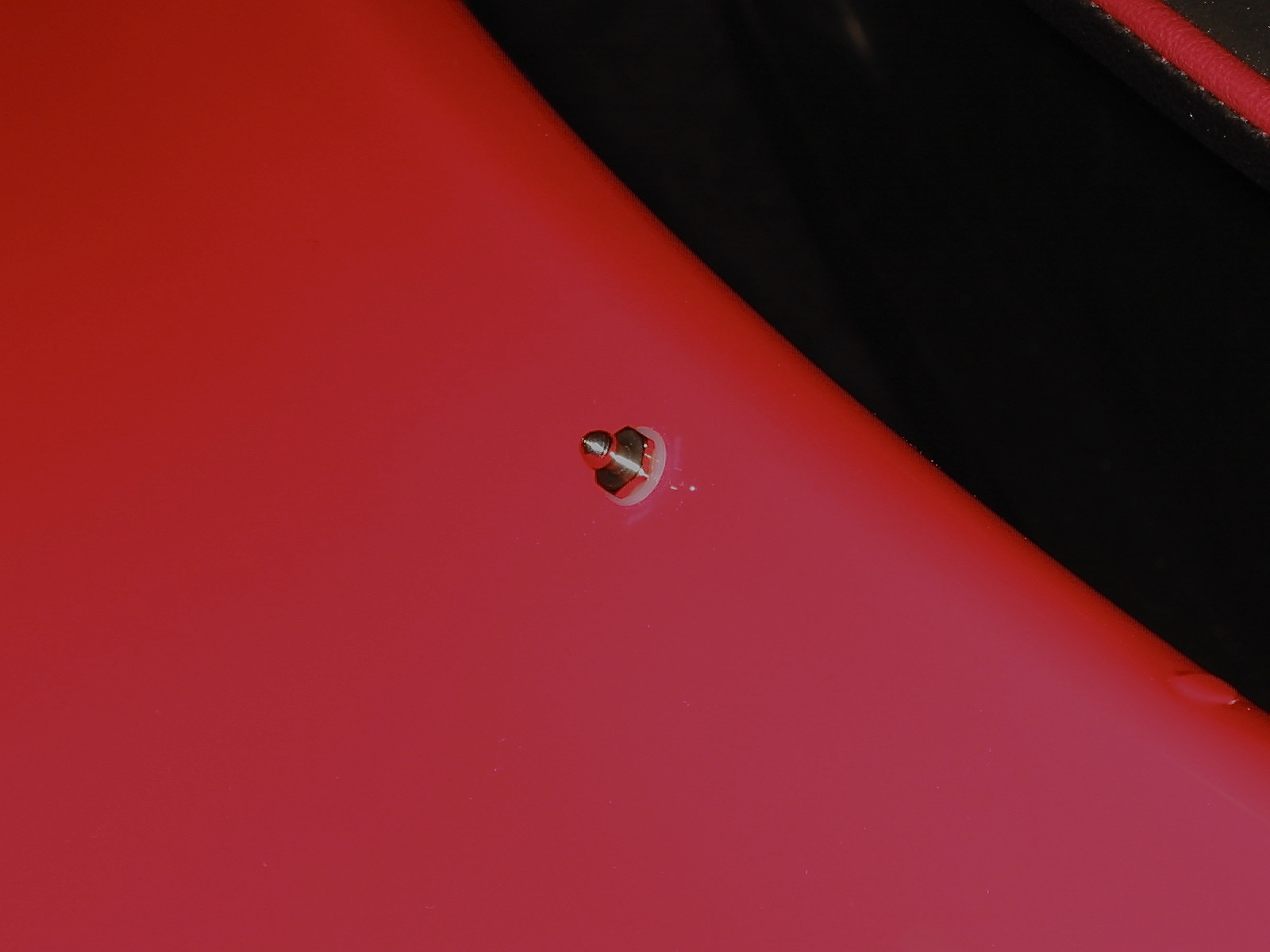
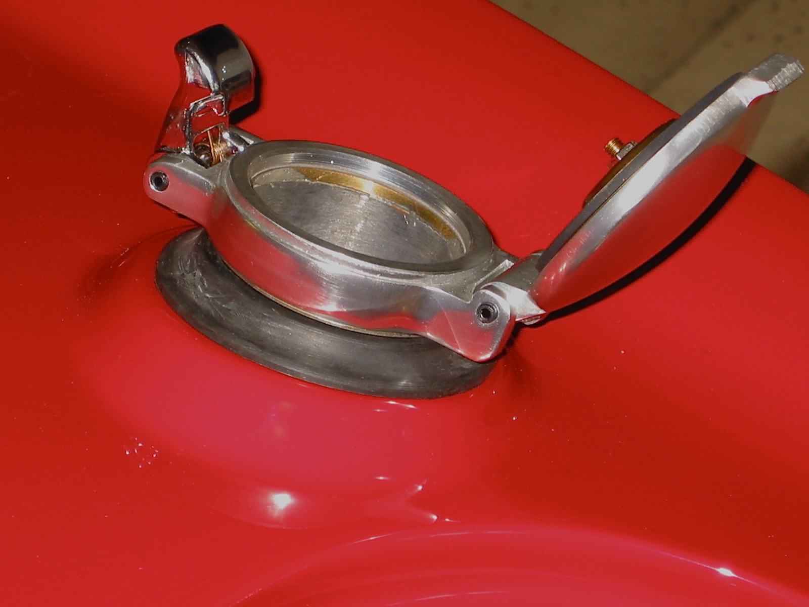
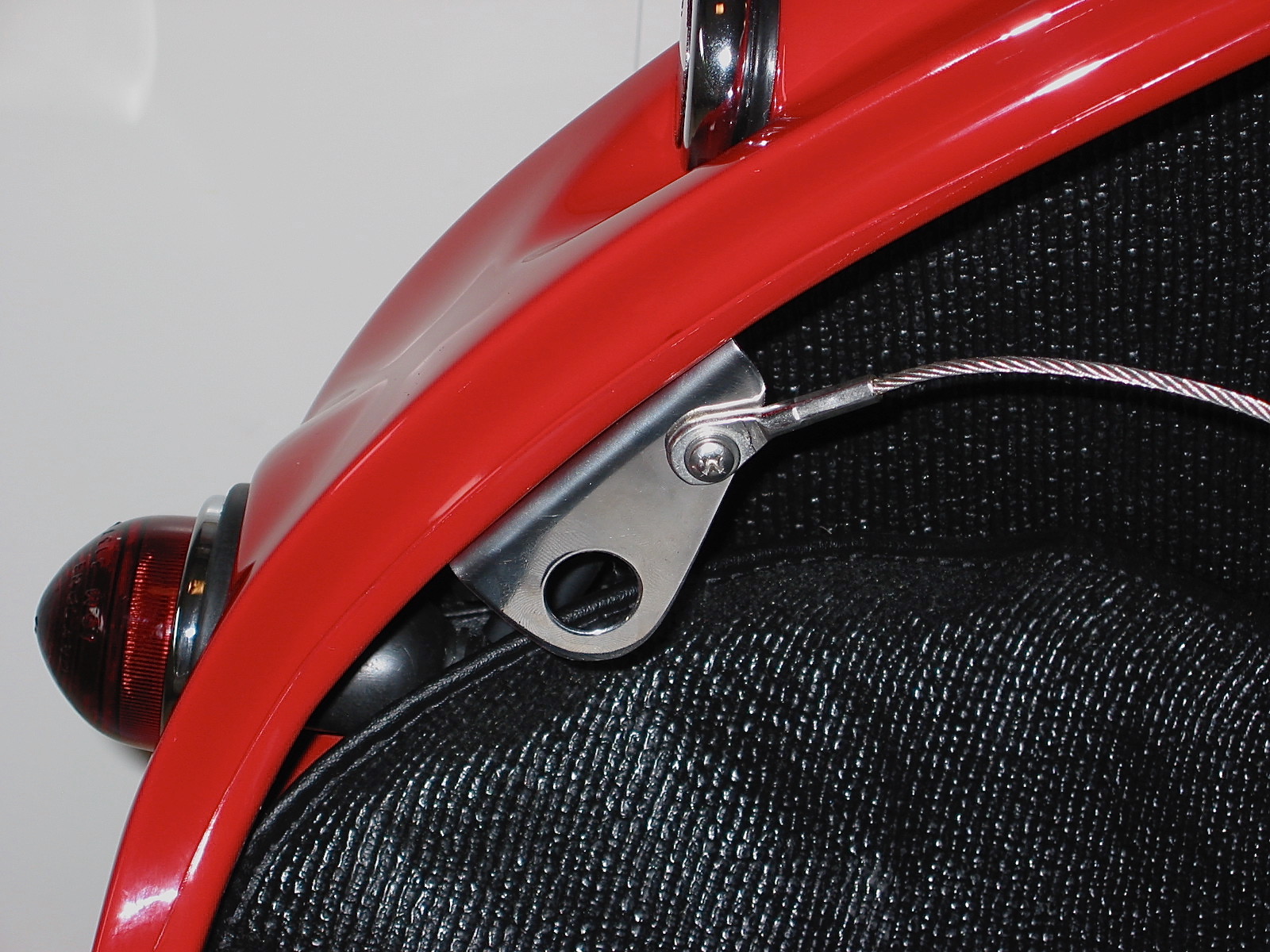
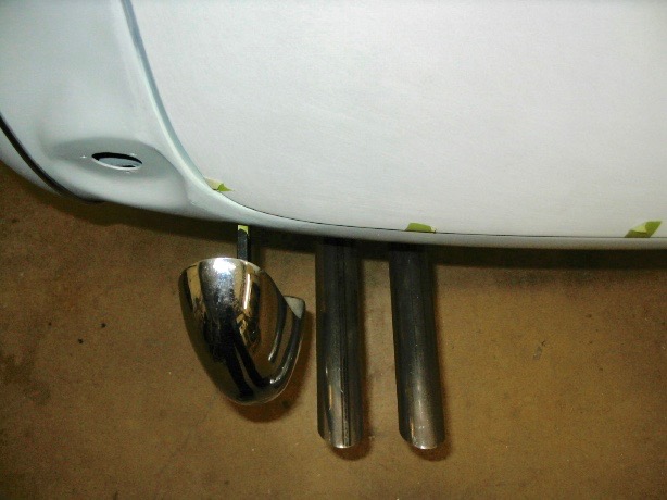
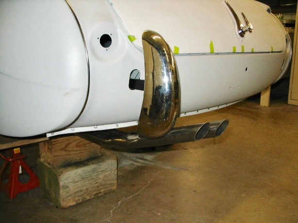
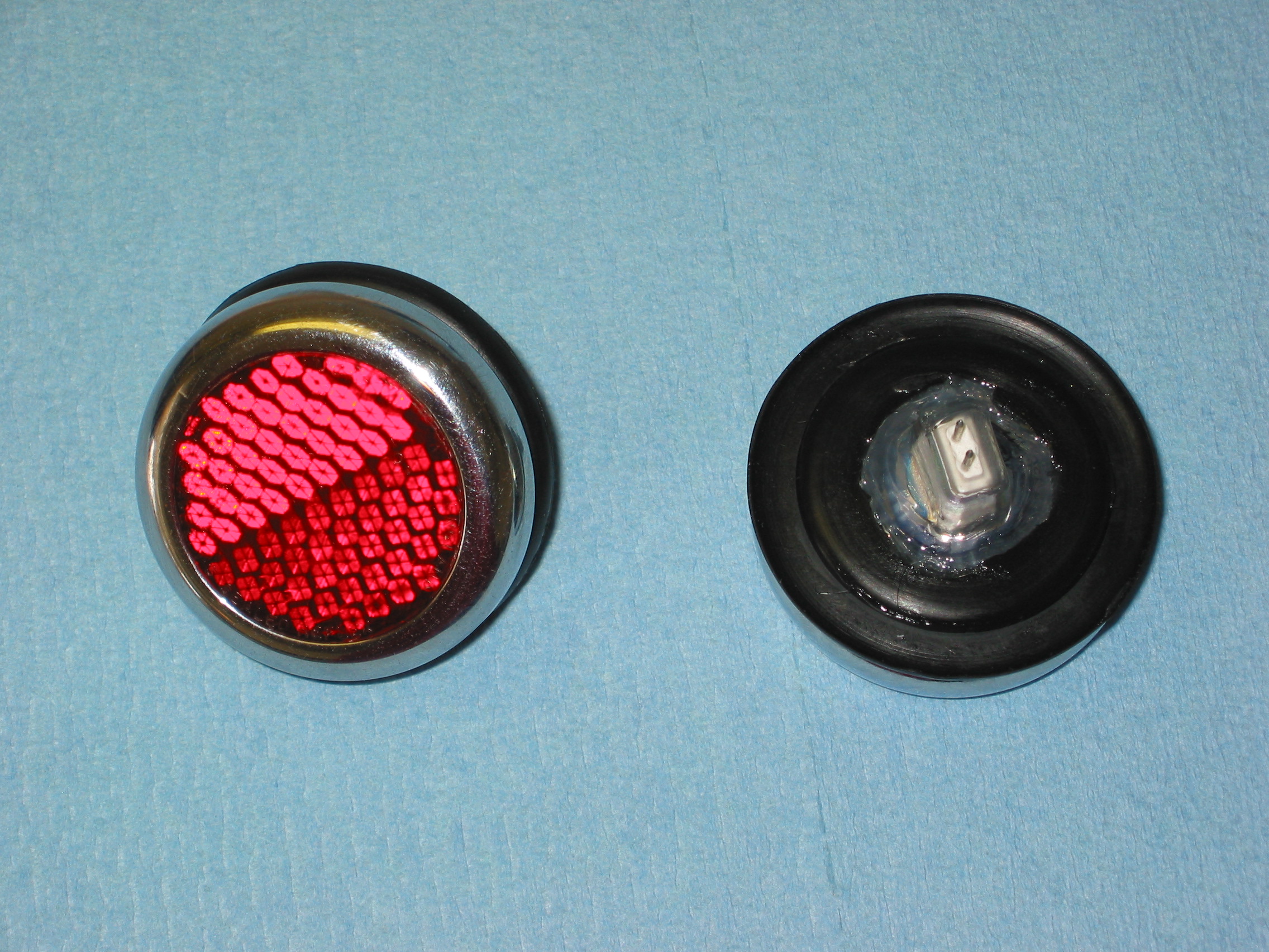
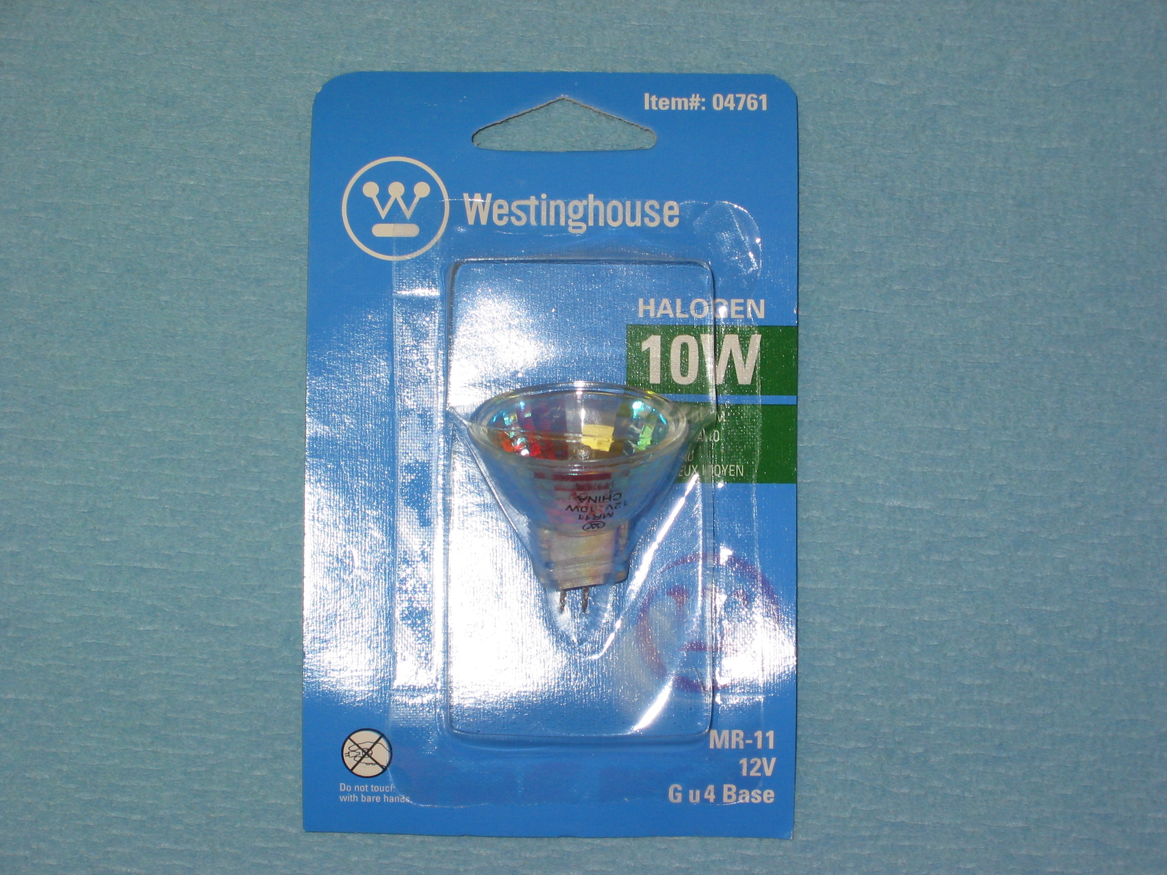
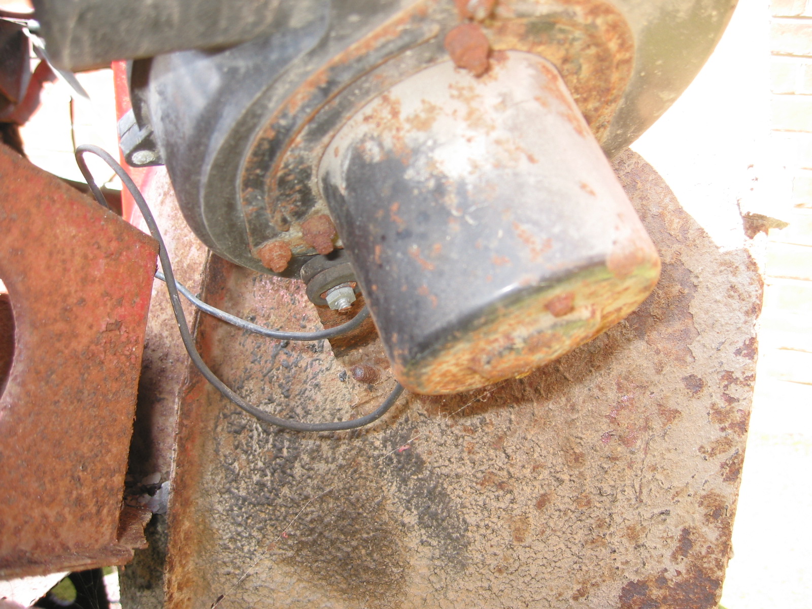
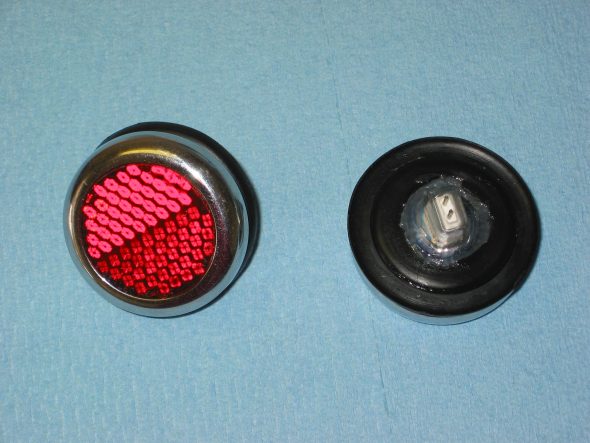
Rear lights on Healeys leave something to be desired. I came upon a web site that offered a good idea for adding some rear illumination without any obvious physical modifications. It involved converting the rear reflectors to working lights using a pair of 10 watt,12 volt MR11 halogen bulbs that I found at a local lighting store. I also ordered two connecting terminals on-line since the connectors are very small and somewhat delicate pins.

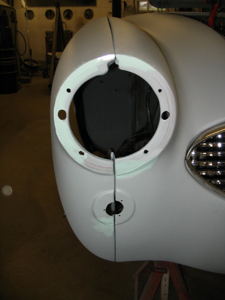
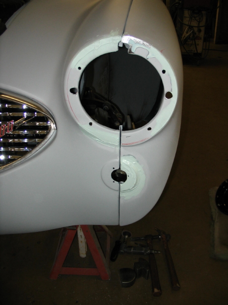
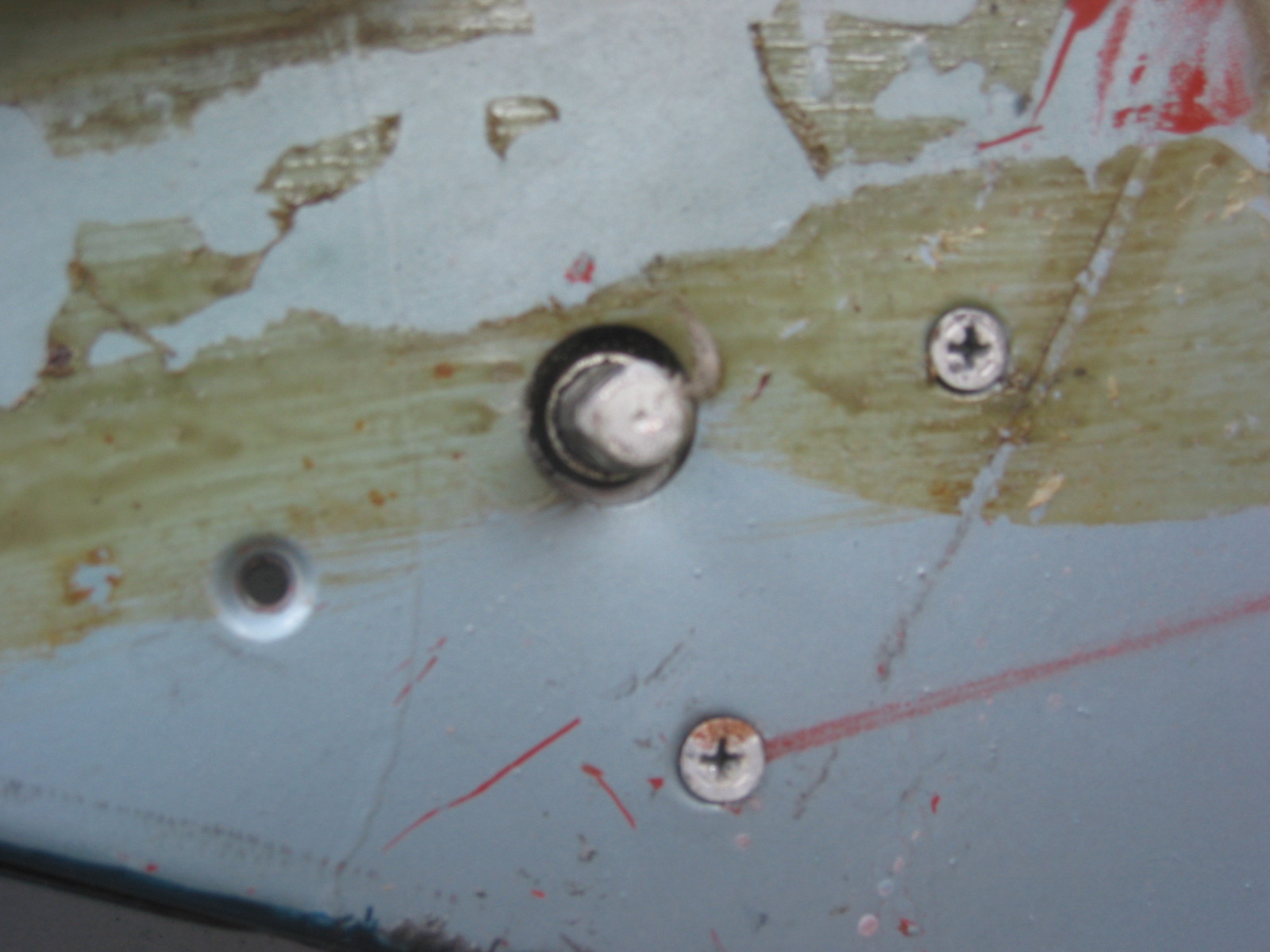
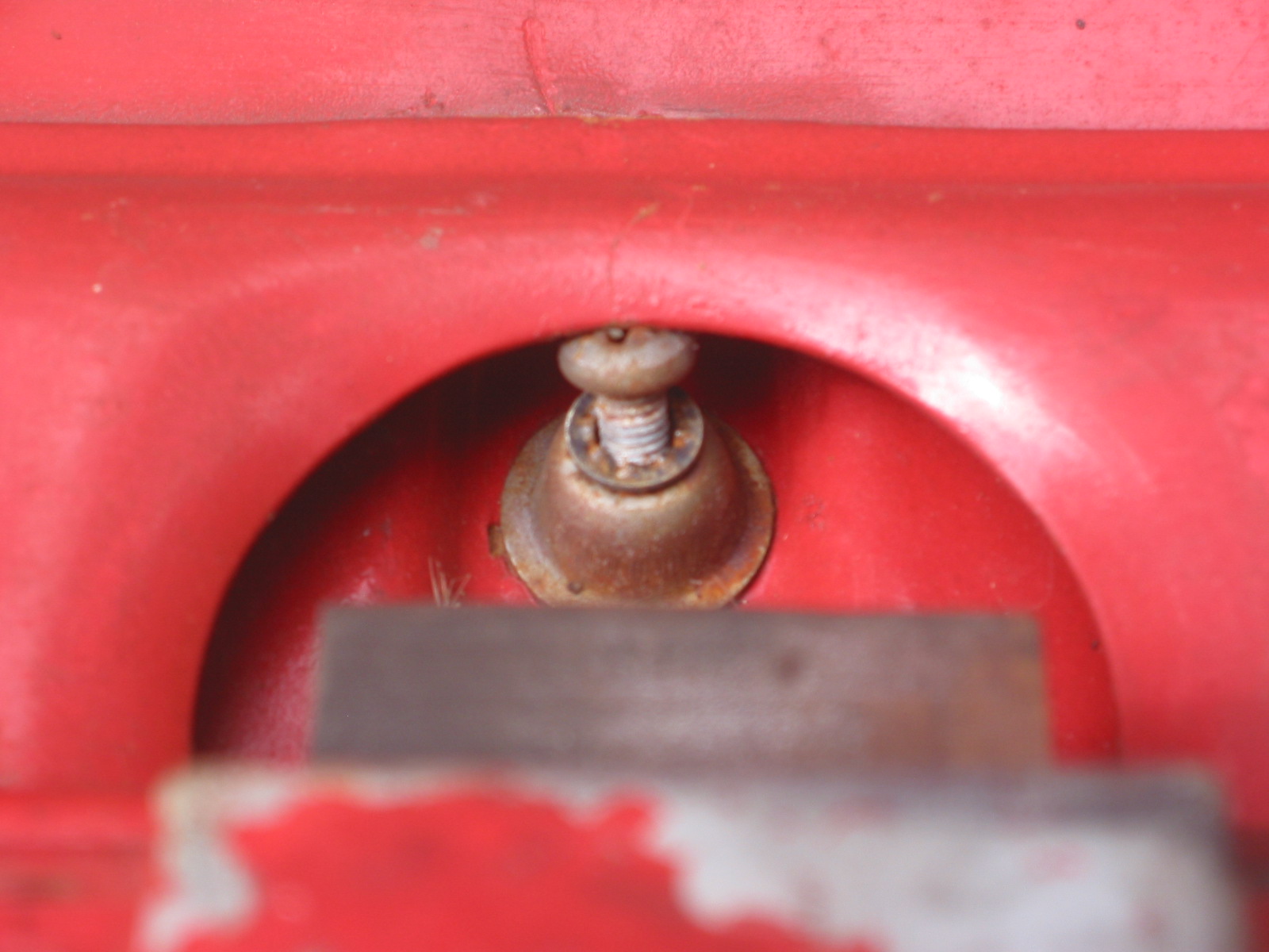
As per the directions on the Healey Club of Ontario web site, I removed the rear reflectors from their pods. I dicovered that this works with the original reflectors but not with those currently available! The reproductions are not as deep and do not have the foil reflector. The easiest way is to carefully insert a small screwdriver between the chrome bezel and the rubber ring. Pull the chrome bezel off, remove the red reflector, and the rubber body will easily pull out of the hole.

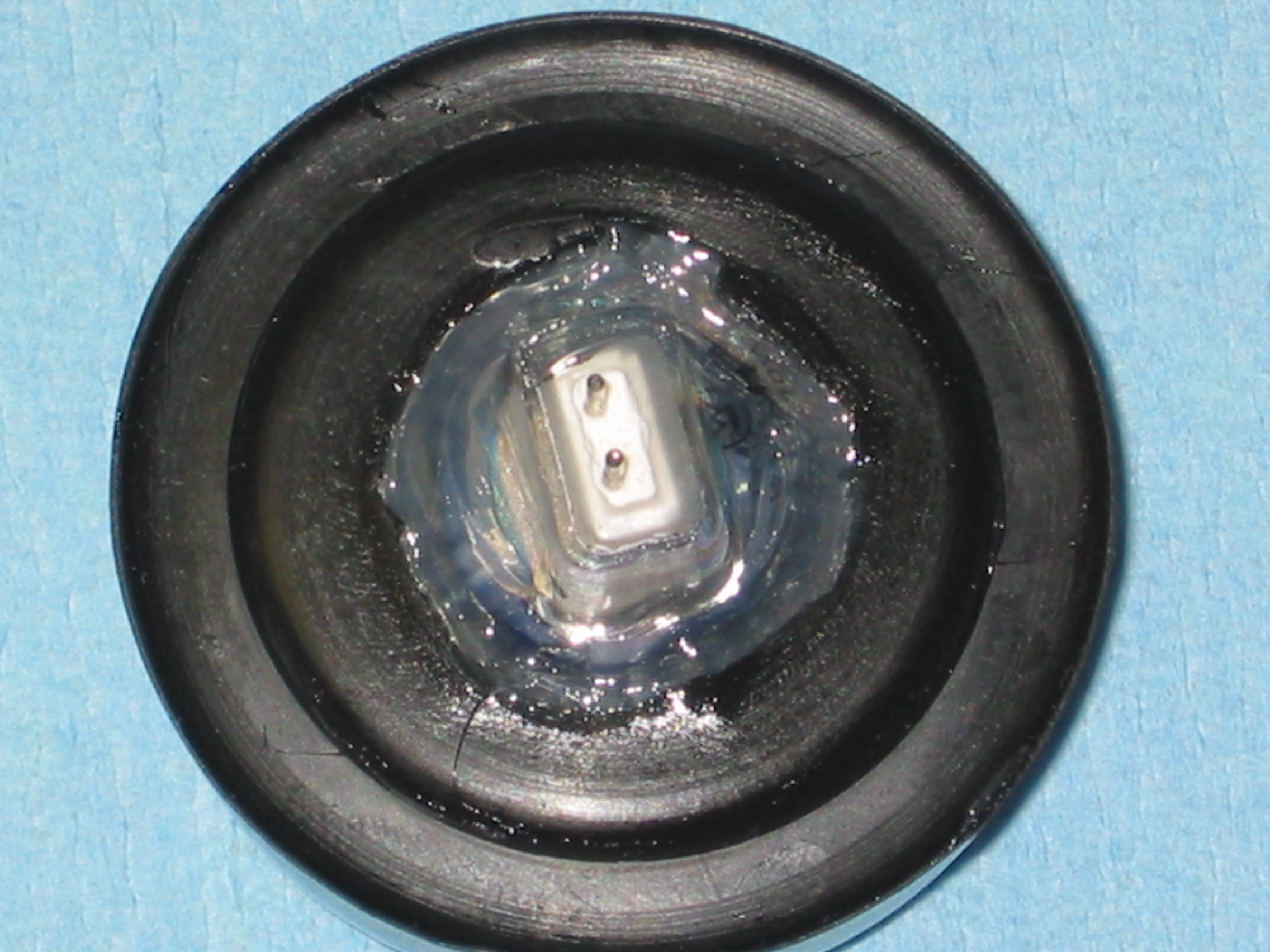
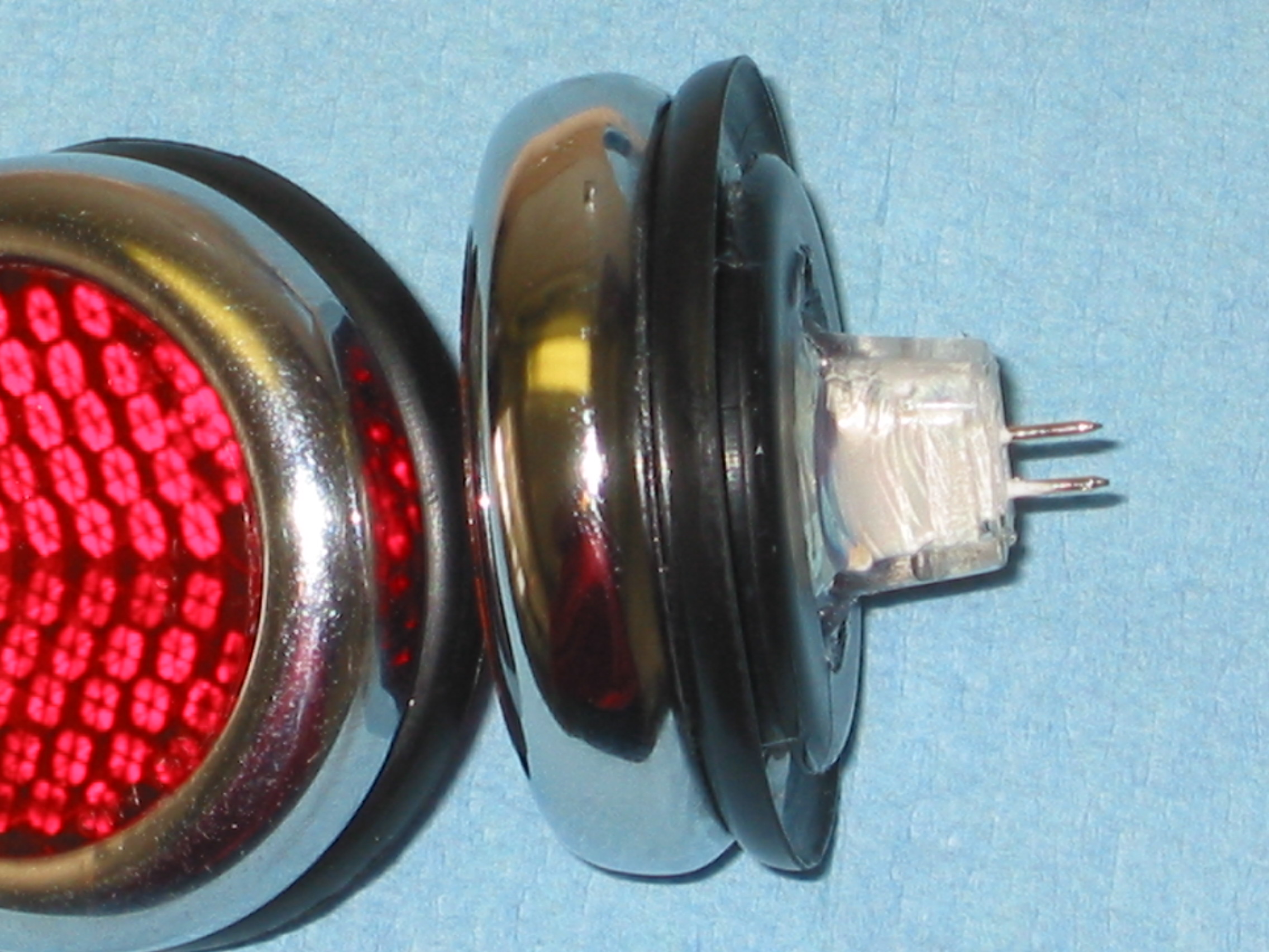
I removed the silver foil from the reflector and drilled a 1″ hole in the center of the rubber grommet. I then trimmed the hole to create an
inward taper into the reflector body to match the cone of the new bulb. Then I secured the red reflector to the grommet, sat the halogen bulb inside and pressed the assembly together. This is not real easy to do. I added a little dishwashing soap to the rubber to make it simpler to press things together. After assembly, I used a bead of silicone to seal the new bulb to the rubber grommet.

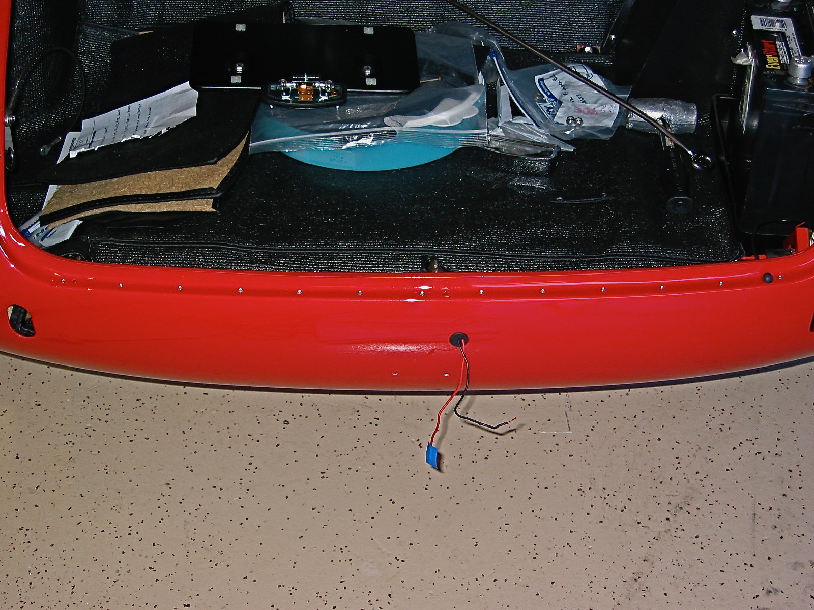
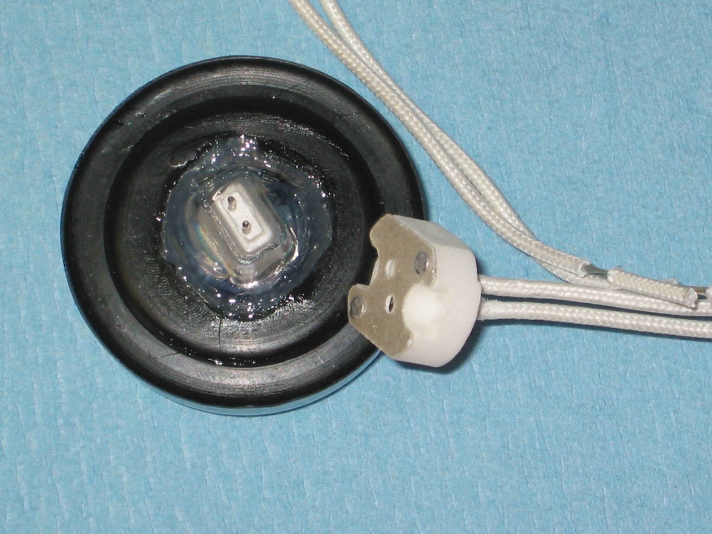
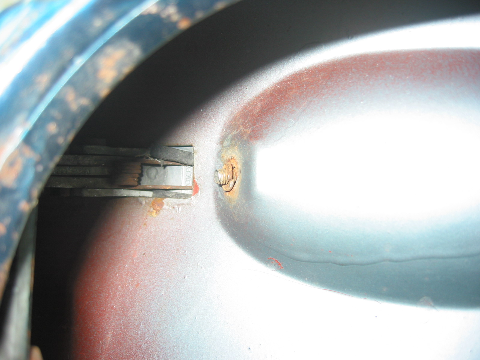
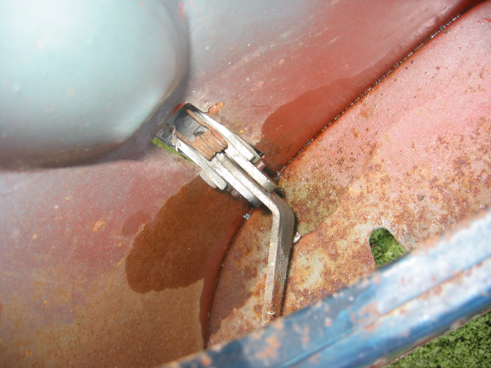
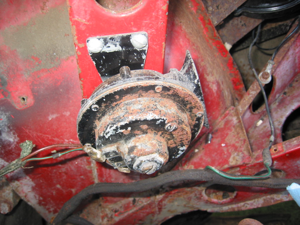
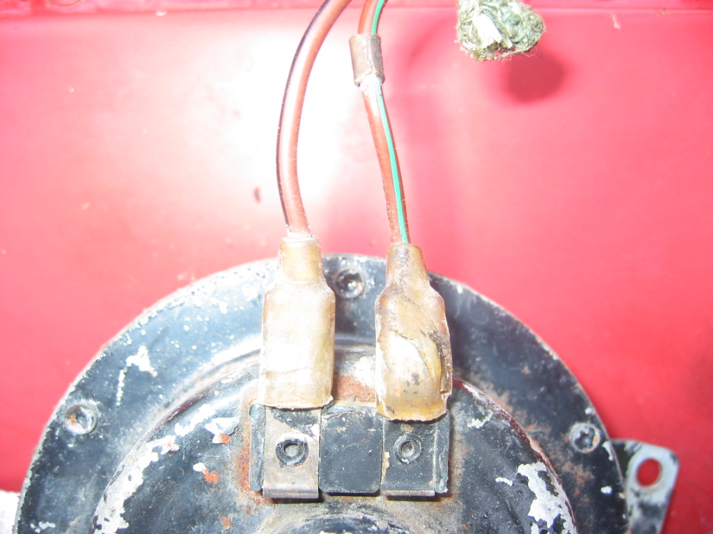
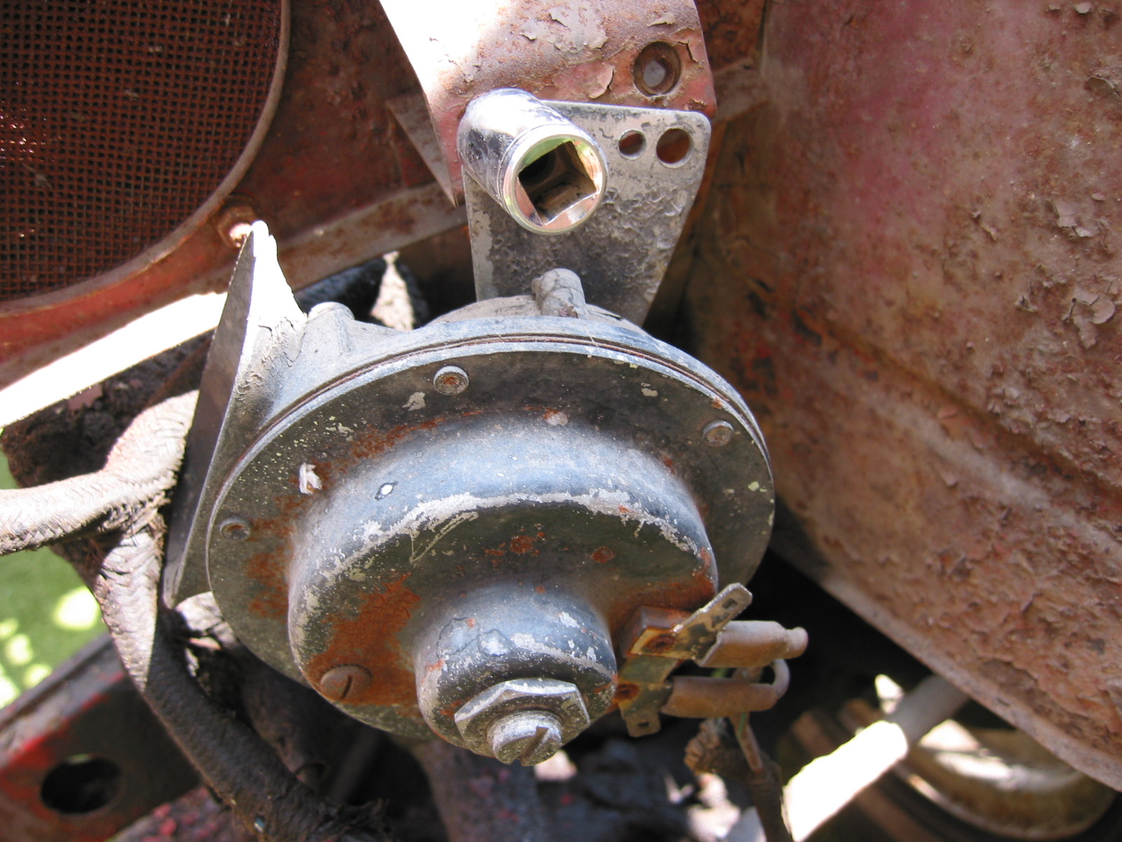
After installation on the car, run wires from the two brake light terminals in the trunk to each reflector pod and from the wire ground screws on each side to the same pod. The bullet connectors for the brake lights are in the boot on the driver side at the rear. I used bullet connectors and changed the single bullet holders to double so I did not have to spice into the wires. Driver side is White with Purple trace and Passenger side is White with brown trace. Since these will
light both with brake and turn signals this is important.

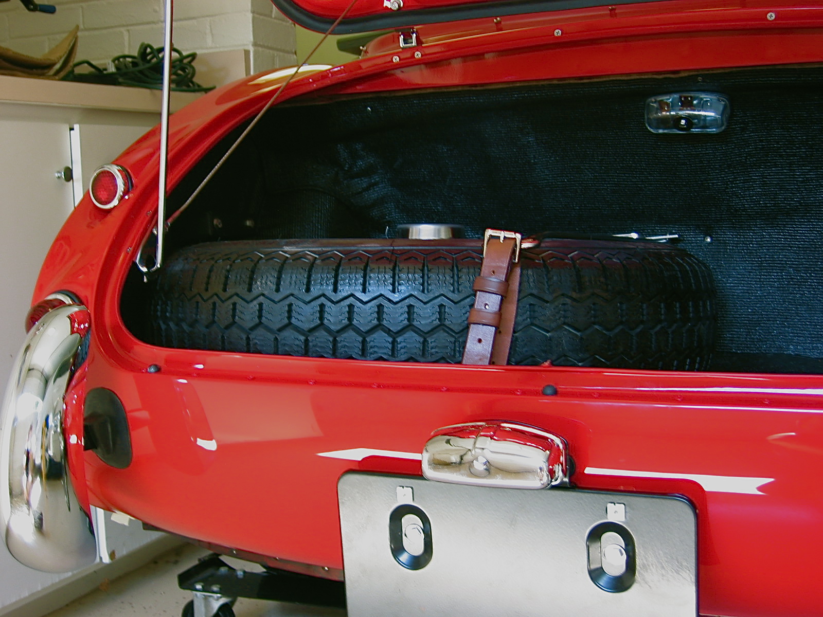
Rear modified reflectors 2

Rear modified reflectors 3

Rear modified reflectors 4

Rear modified reflectors 5
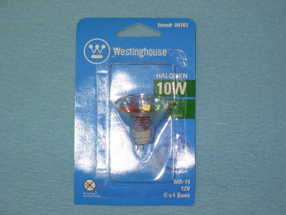
Halogen bulb


Chapter 7 – Disassembly

Front Shroud

Removed five cross head drive screws at the rear of the bonnet. Three screws with nuts must be removed at the front of the shroud at the bonnet opening. Two cross head screws and nuts also attach the shroud to upright posts. A third bolt and nut holds the prop rod bracket. Five pop rivets were drilled out along the scuttle. Two additional rivets must be drilled out along each side and where the rubber seal attaches to the scuttle. Two bolts securing the shroud to each frame extension in the front must be loosened from their nuts. The shroud can then be released from the rear and pulled forward.

Prop Rod Bracket Removed

Rivet Removal

Front Shroud to Frame Mount

Shroud Removed 1

Shroud Removed 2

Rear Body Panel (shroud)

The rear body panel is released by first drilling out 19 rivets along the lower lip. Thirteen rivets must be drilled out that hold the body panel to the luggage compartment frame. Two or three rivets must be drilled out on the side of the rear body panel where the wing fastens to it. Four cross head screws and nuts must be removed from the top lip of the boot opening. The rear body panel can then be removed. Care must be taken to not bend the small front lip on the aluminum panel at the front points.

Rear Shroud 1

Rear Shroud 2

Doors

Removed three posidrive screws holding the interior door handle. Removed four posidrive screws at rear of door by handle. Removed opening mechanism. Loosen phillips head screw in door handle accessible when the door handle is pulled. 5/16” nut on the door handle screw. Loosen 5/16” nut on the screw on the back of the door handle – not easy to get to! Door handle can then be extracted from the door.

Interior Door Handle

Exterior Door Handle Fastener

Door Latch

Door Fasteners

Removed side curtain bezel and retaining nut and chrome washer. Removed mid-door wood strip. One pozidrive screw on top center and two screws to the left and right on the bottom side. Removed the door strap (catch). 

Door Catch Mechanism

Interior Door Trim Panel Wood

Door Opener Mechanism Orientation

Remove door hinges. Four bolts into a securing plate for each hinge. Drilled small indentation into the top bracket to recognize it. On reassembly of doors mount outside door handle first. Then install mechanism so that the action arm is in the proper place.

Door Catch at Door

Door Hinges

Aluminum Door Hinge

Boot Lid 

Removed two screws and cup washers securing the handle/lock. Remove four bolts/nuts holding the lock/catch mechanism. Remove one screw holding the locking mechanism post. Lock surface was painted as were the screw tops so it was installed when the car was painted. The chrome lock and handle were installed after the car was painted because the locking post screw was not painted.

Exterior Boot Lid

Interior Boot Lid

Boot Lock Handle

Boot Lock

Removed the large cotter pin holding the rubber boot lid support rod. The rubber could then be removed as well. The head of he pin was located on the rod locator bracket side. A small cotter pin was removed from the support rod at the home bracket. The rubber grommet was then removed and the rod was detached.

Removed rubber gasket sealing boot lid.

Boot Rubber Seal

Boot Prop Rod Clasp

Heater Blower Assembly

Removed four nuts on posts through rubber grommets. Black ground wire connects to the angle pillar. Power is through a green wire with a brown stripe that plugs into a rubber junction. 

Removed the two heater blower mounting brackets. Two bolts each through wheel well arch. Large washers used on the tire side of the arch.

Smith’s Heater Blower

Blower Mounting Location on Frame Upright

Blower Mounting Rubber Grommets

Blower Motor Wiring Connections

July 28, 2002

Under Bonnet Components

Horns – Located on the left and right of center under the front shroud. Each horn is secured with two bolts fastened into small steel threaded plates. I don’t believe my horns or brackets to be correct as one was mounted on the vertical shroud support like later cars.

Horn on Shroud Upright

Horn Wiring Connections

Proper Horn Location Under Front of Shroud

Horn Mounting Bracket