July 3, 2004
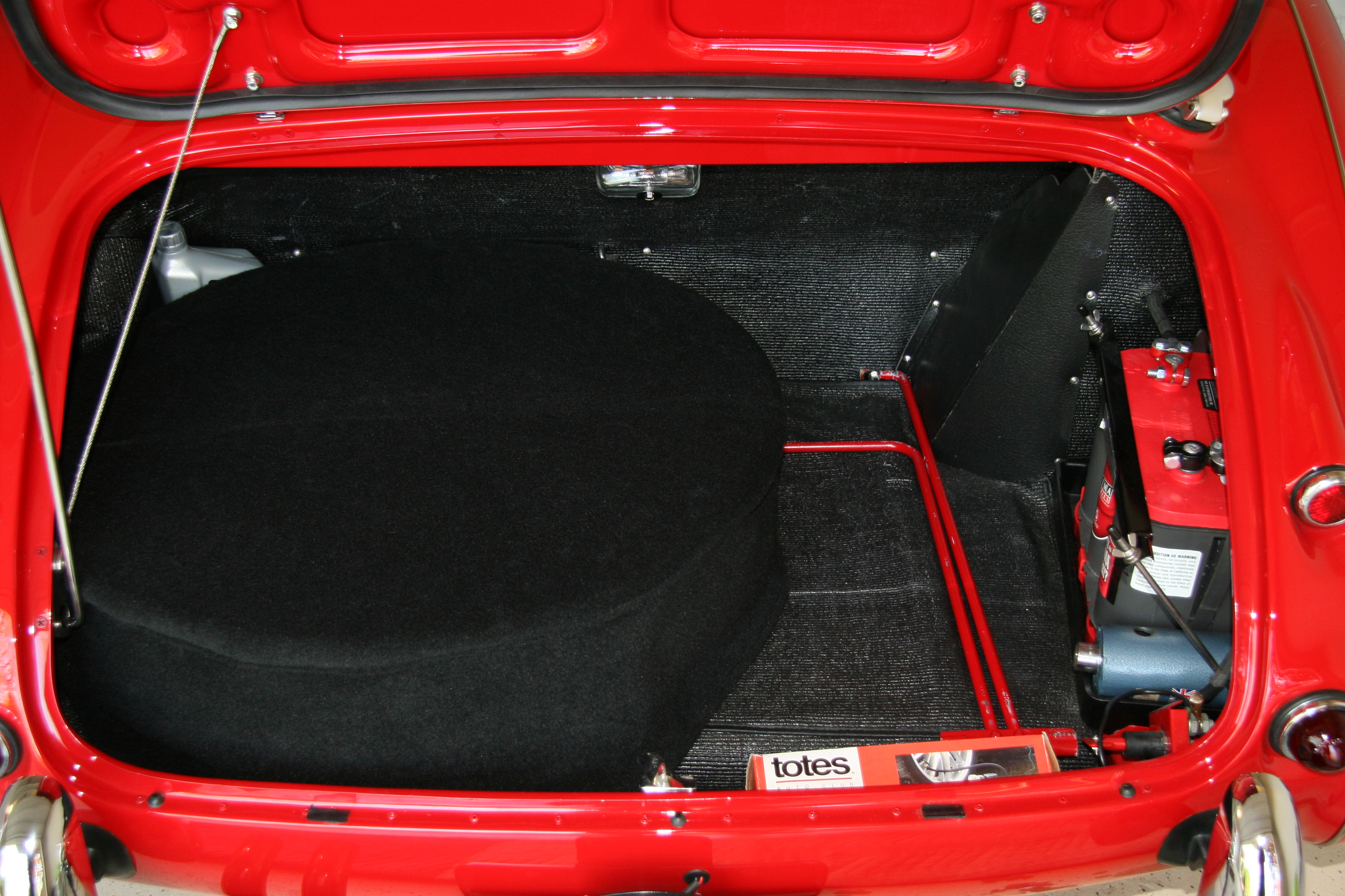
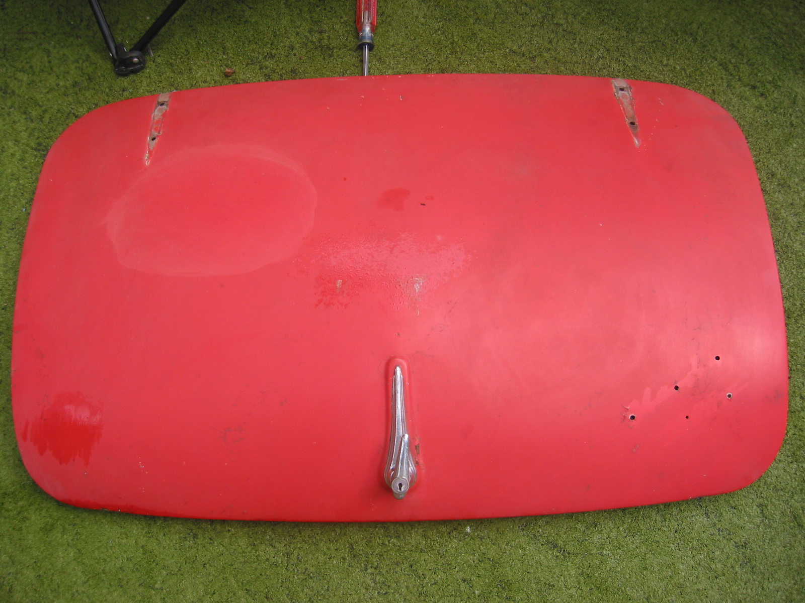
Boot Armacord Liner
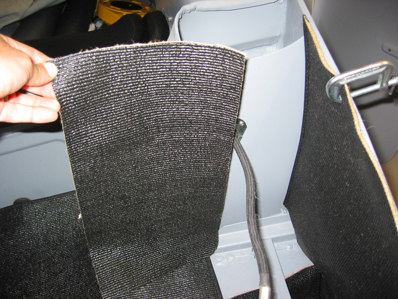
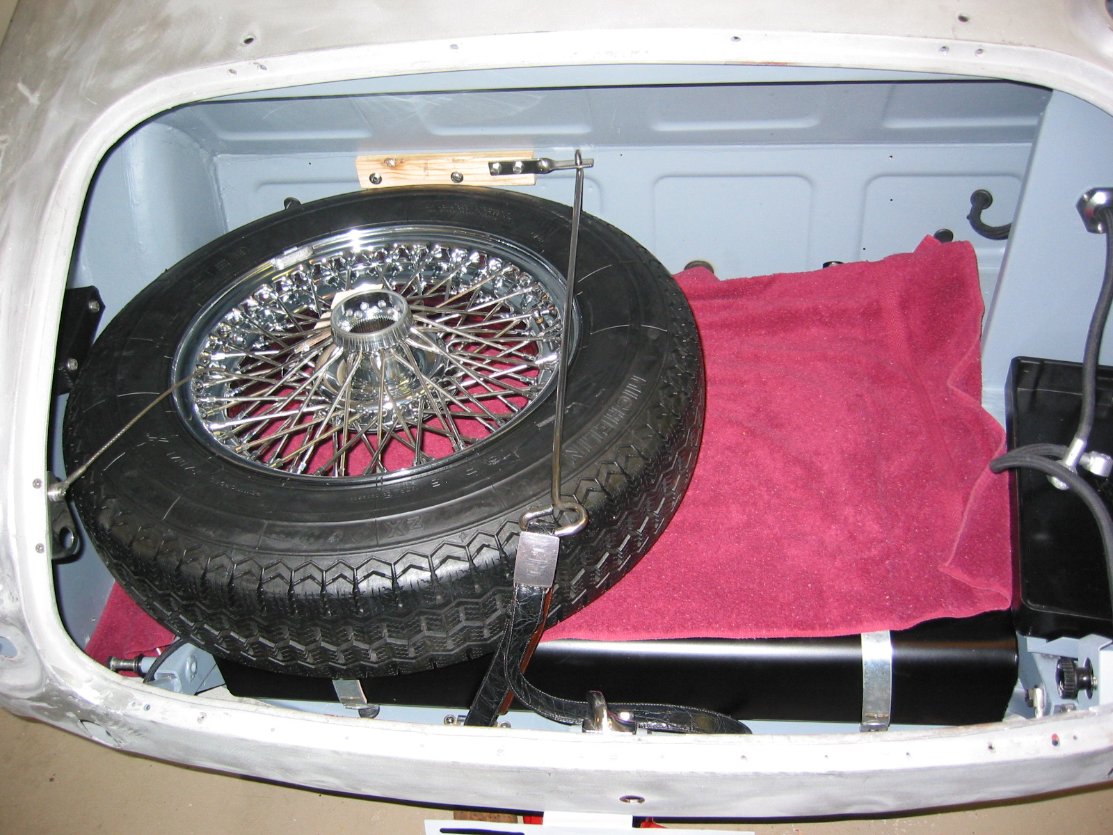
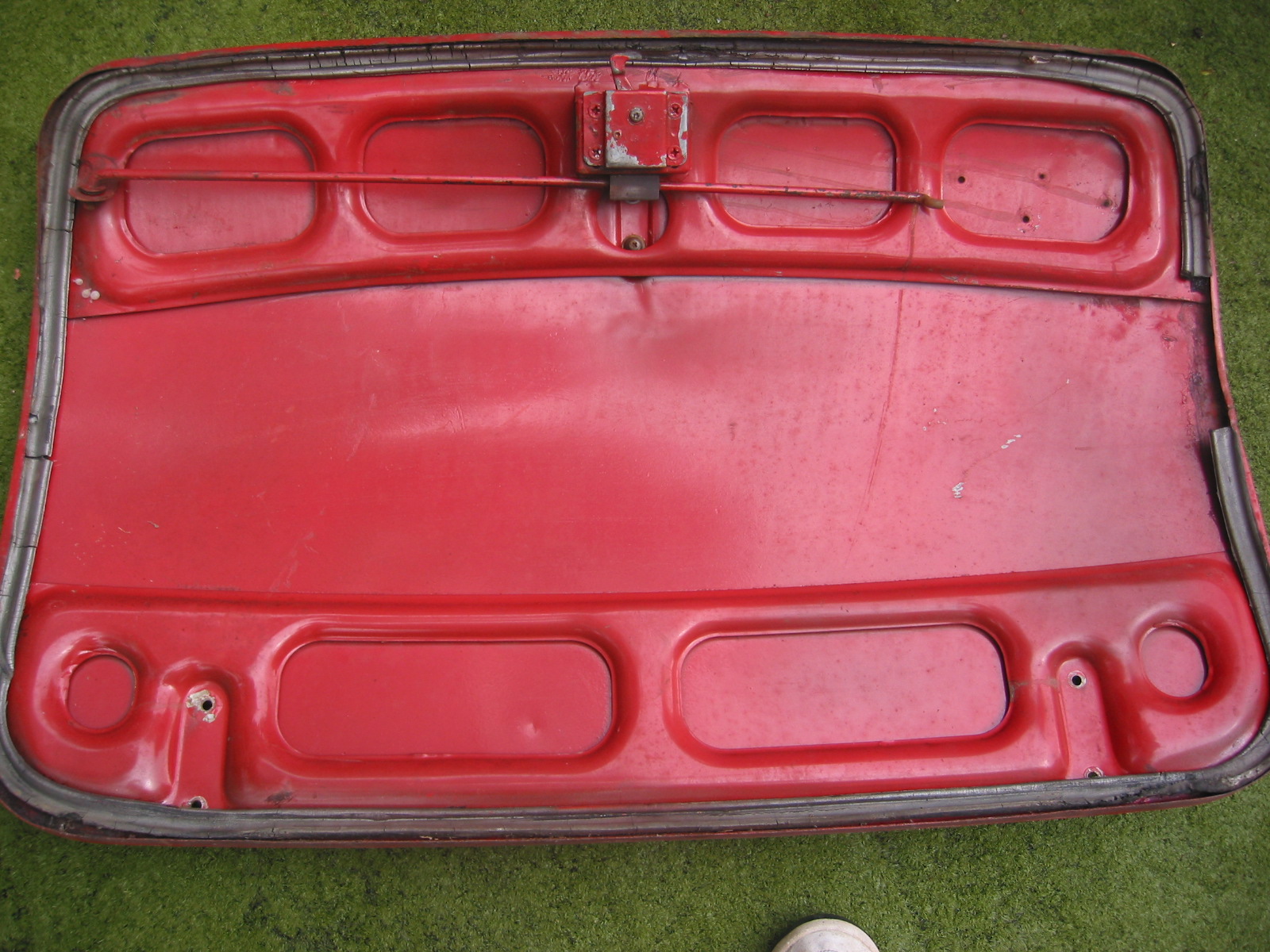
Test installed the boot liner material from Heritage. Won’t be gluing it in until after the car is painted. Everything seemed to fit fine and the material looked great.
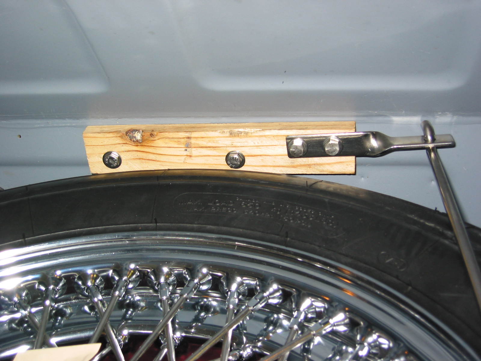
3M spray adhesive is claimed to work well. Install before fuel tank, but after the fuel tank strap brackets are affixed, and before the battery cable fixture is added and before all wood blocks are secured. Be sure to put holes or cuts in fabric.
Install the cardboard fuel neck cover after the tank and filler pipe – will need to drill three holes after material is glued in.
I reboxed everything and stored it in the coat closet downstairs.
The panel install order is below:
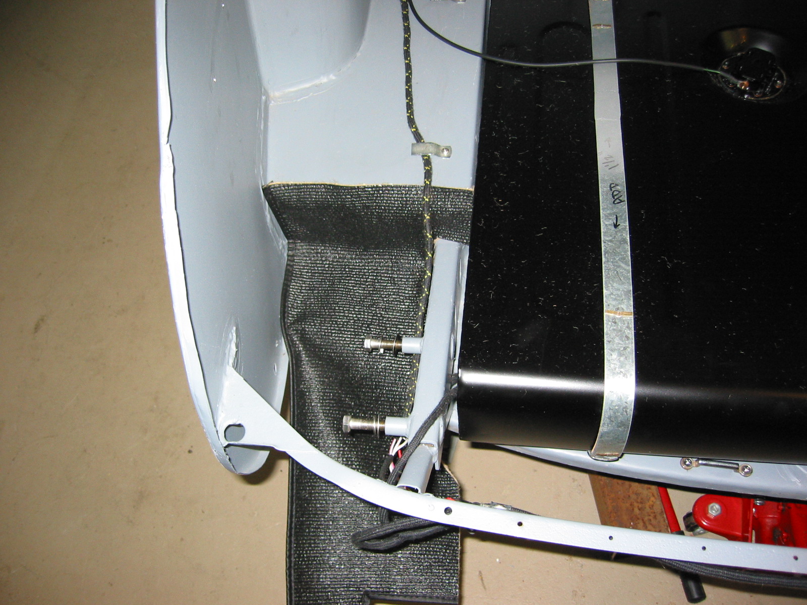
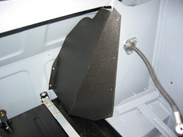
1 Battery cable vertical panel – glue
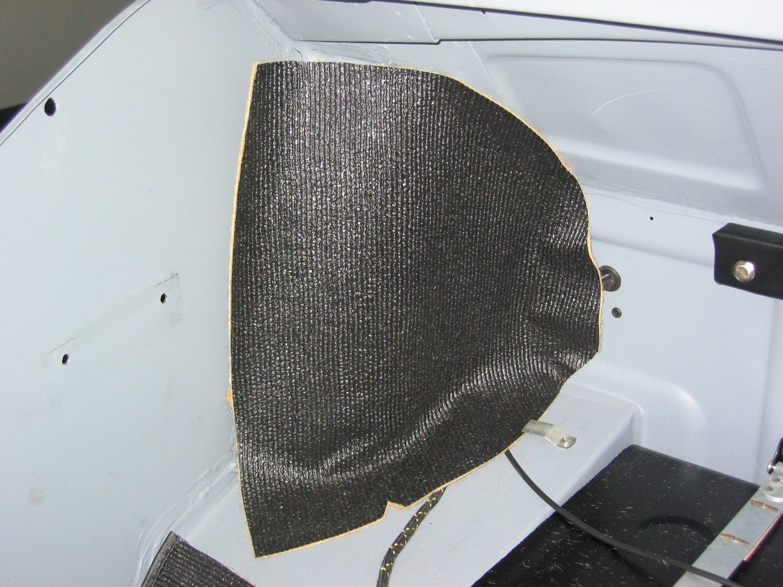
2 Left wheel well curved panel – glue
3 Left vertical wall panel – glue
4 Right vertical wall panel – glue
5 Left floor well – glue
6 Right floor well – glue
7 Back vertical wal -l glue
8 Rear shroud panel ?
9 Floor Panel – not glued

Boot Liner 1
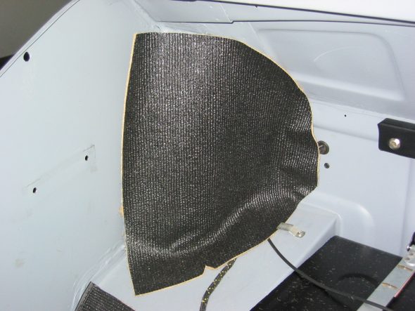
Left Wheel Arch Panel
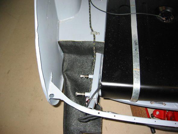
Left Floor Well Panel

Right Floor Well Panel
Fuel Pipe cover
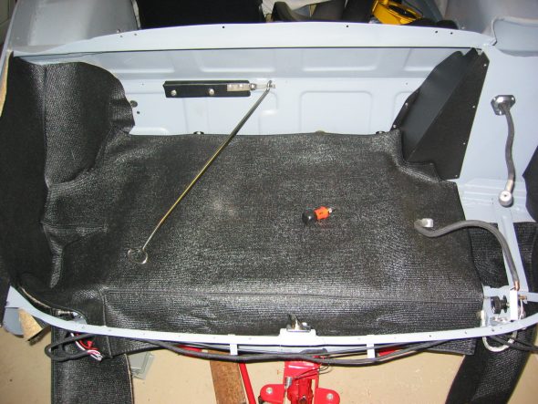
Floor liner Panel
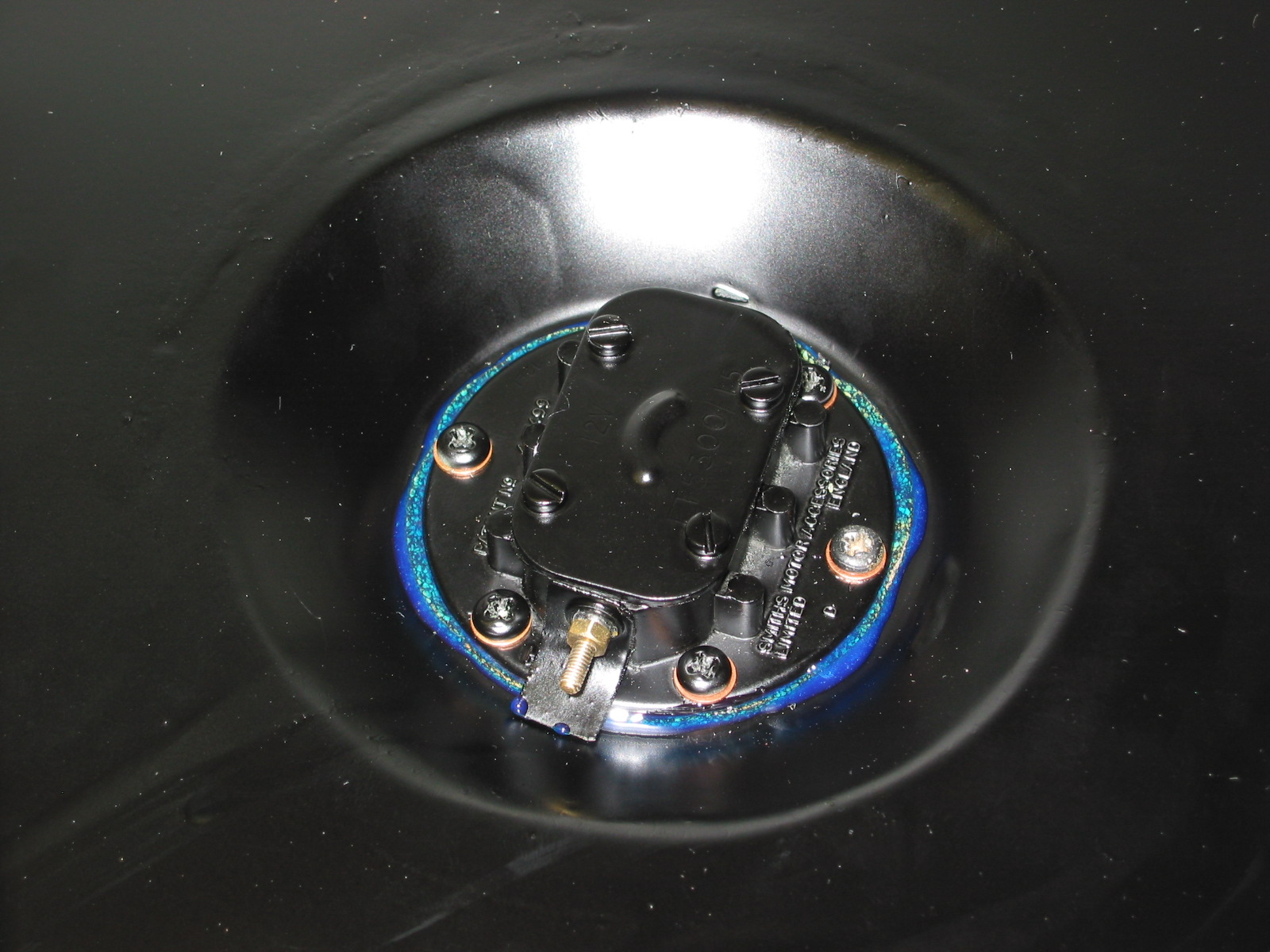
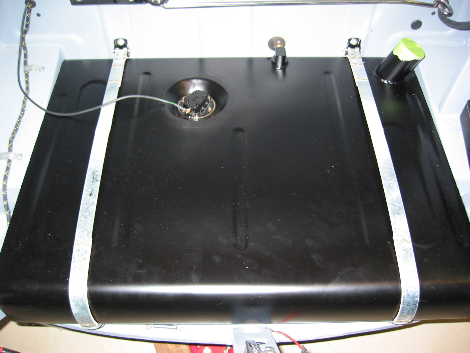
I didn’t think about getting the hylomar sealant in the fuel tank when I sealed the sender unit gasket. I will need to replace, clean, and reseal more carefully.
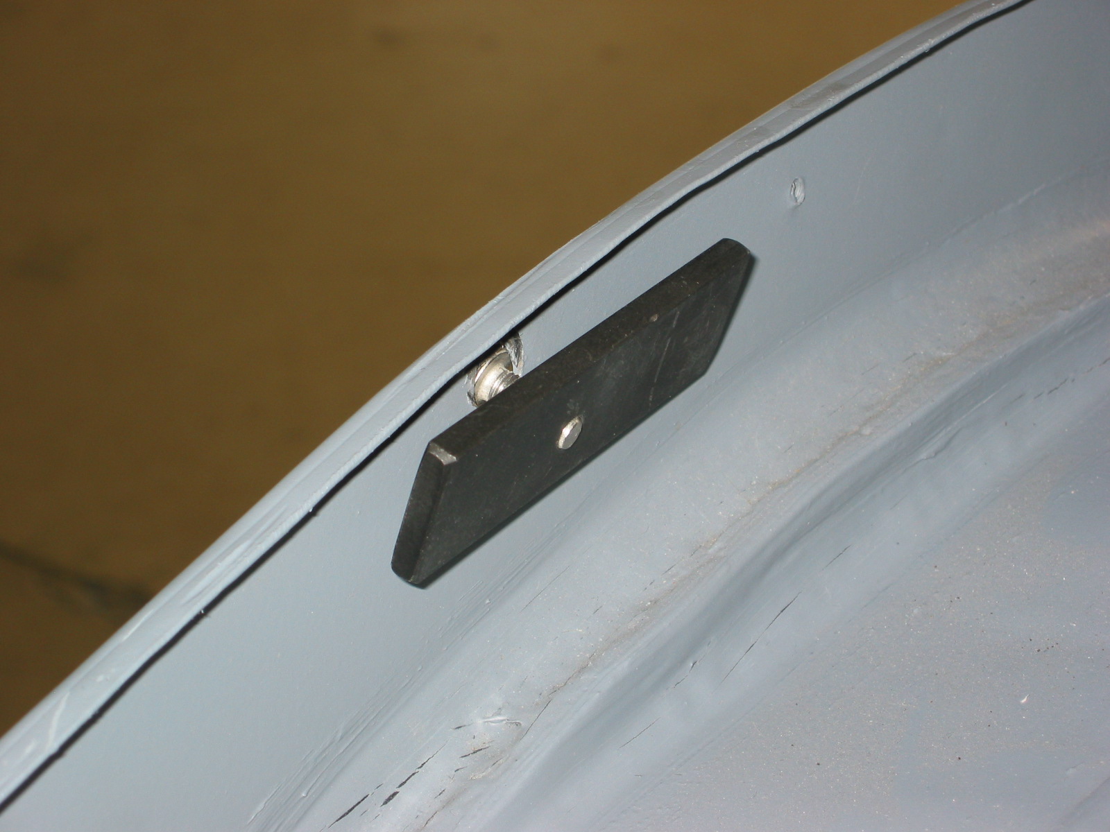
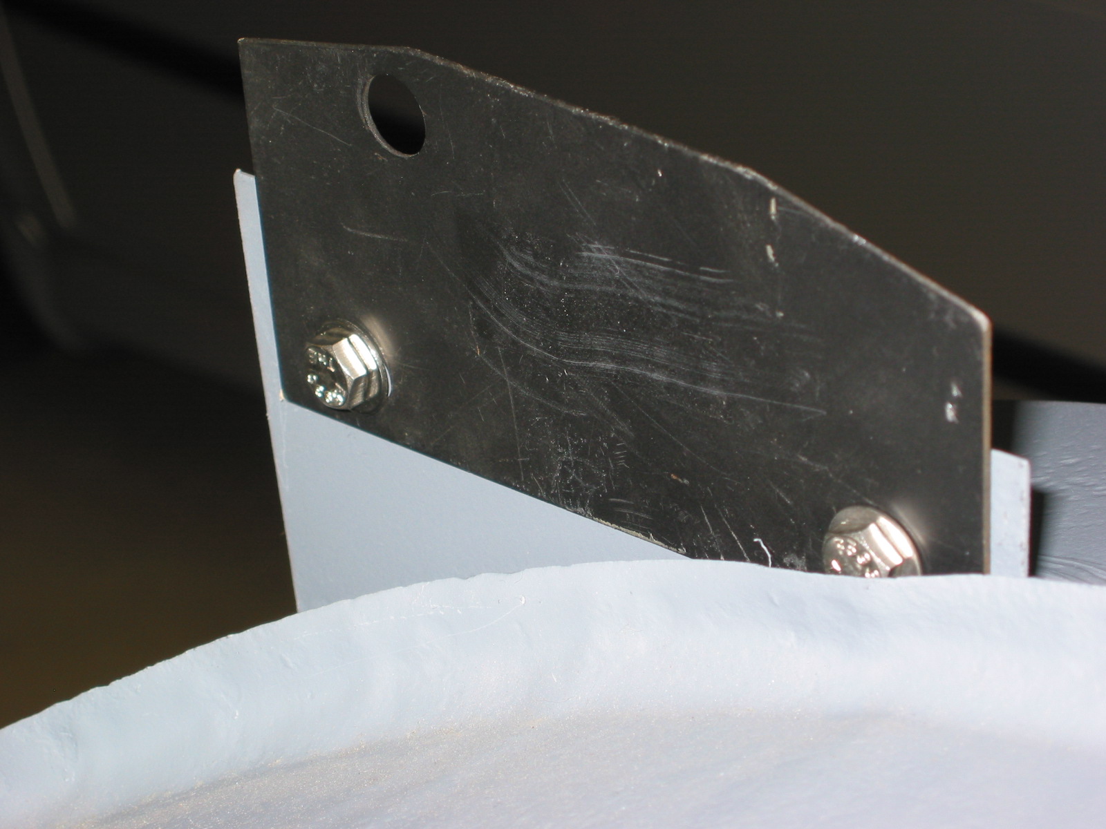
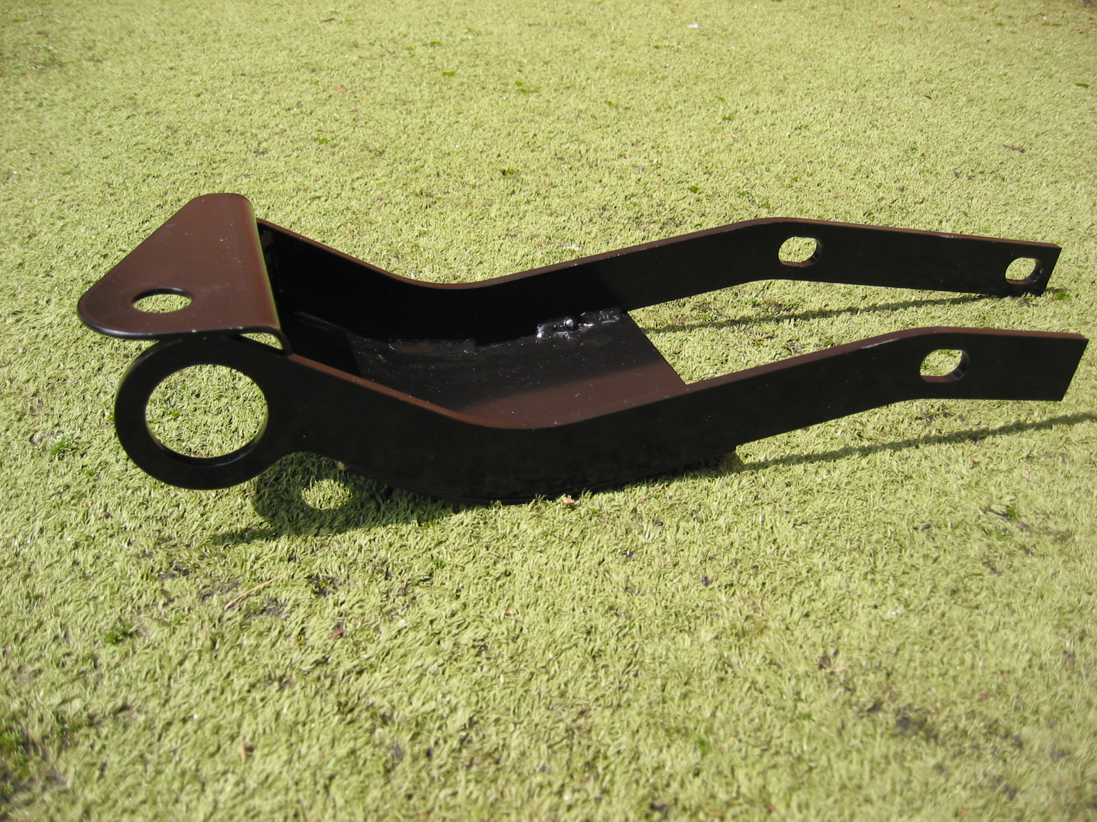
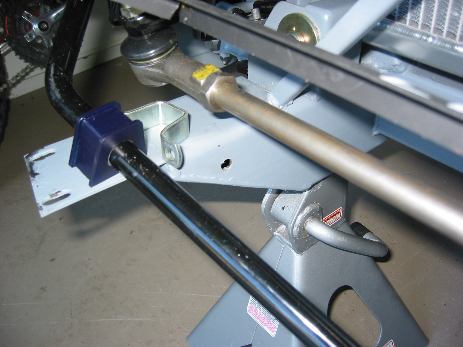
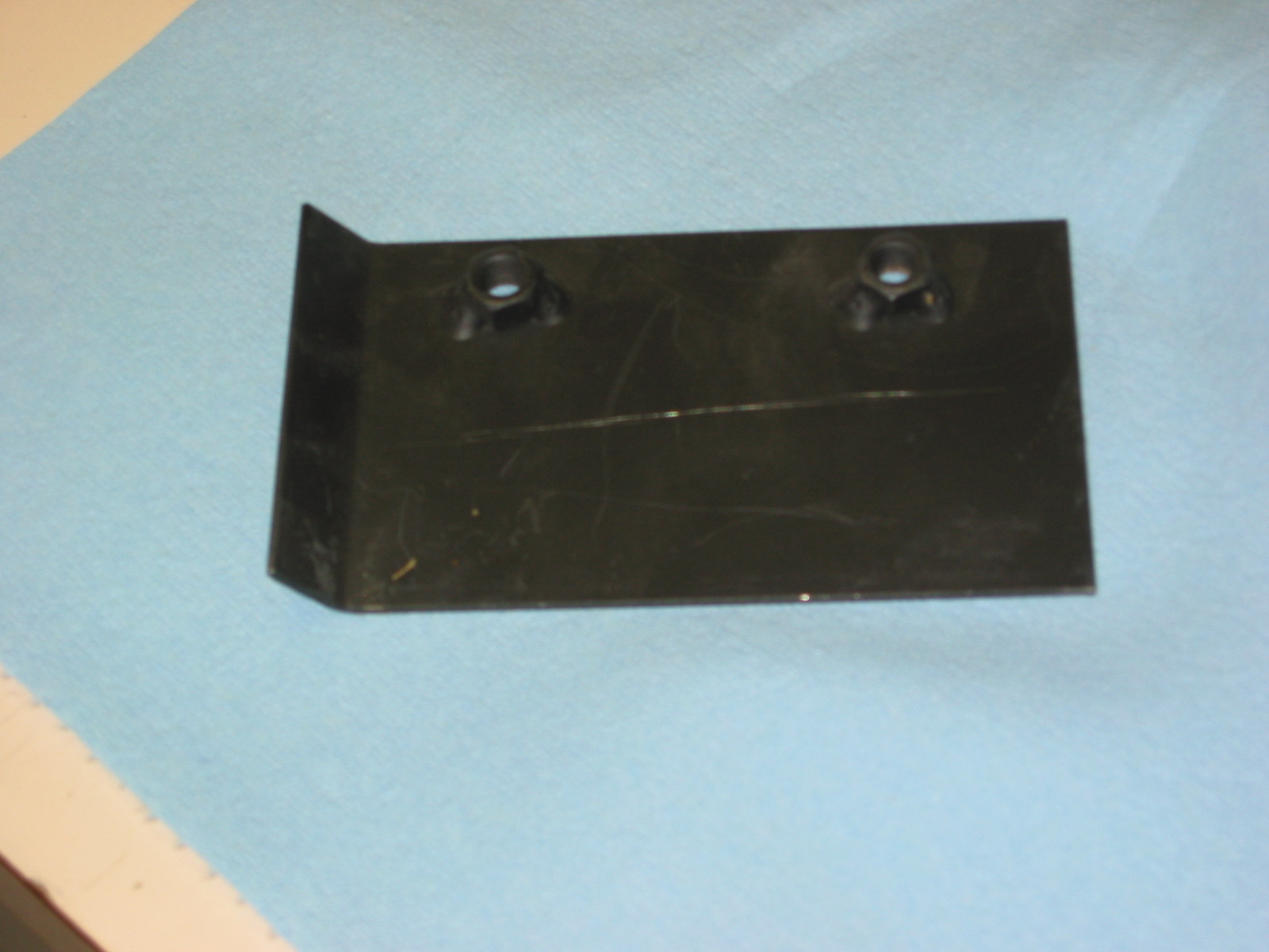
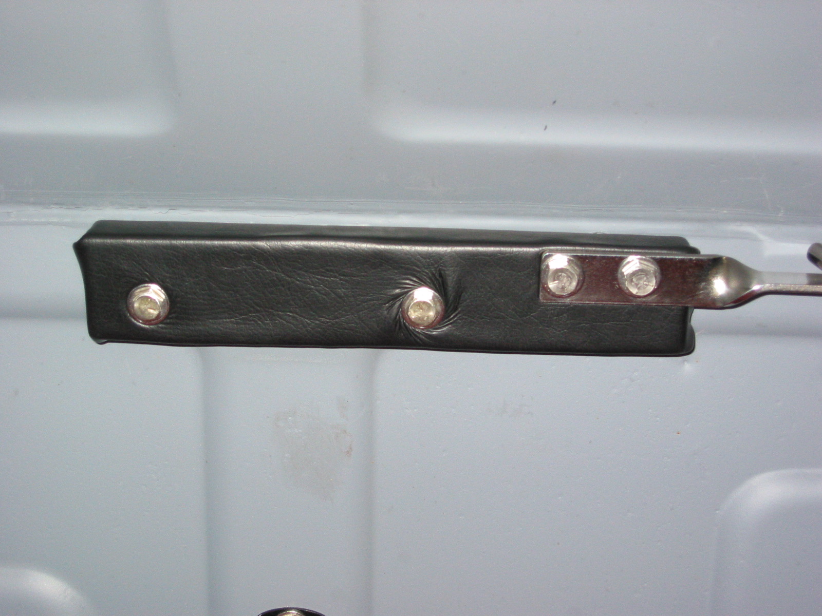
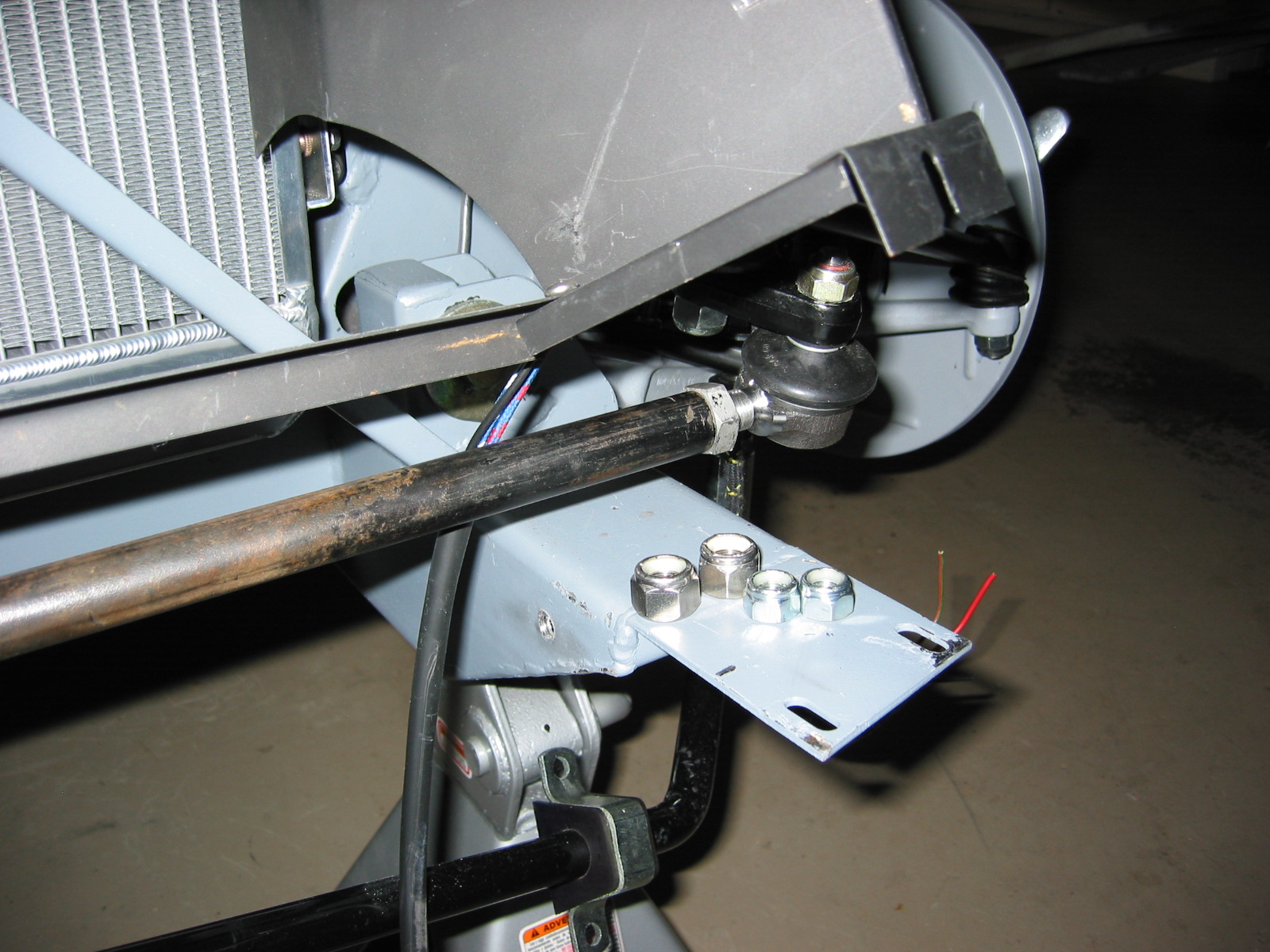
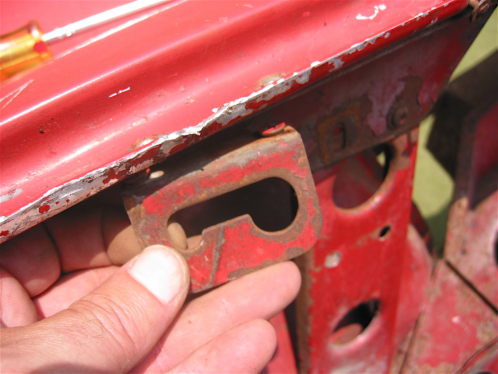
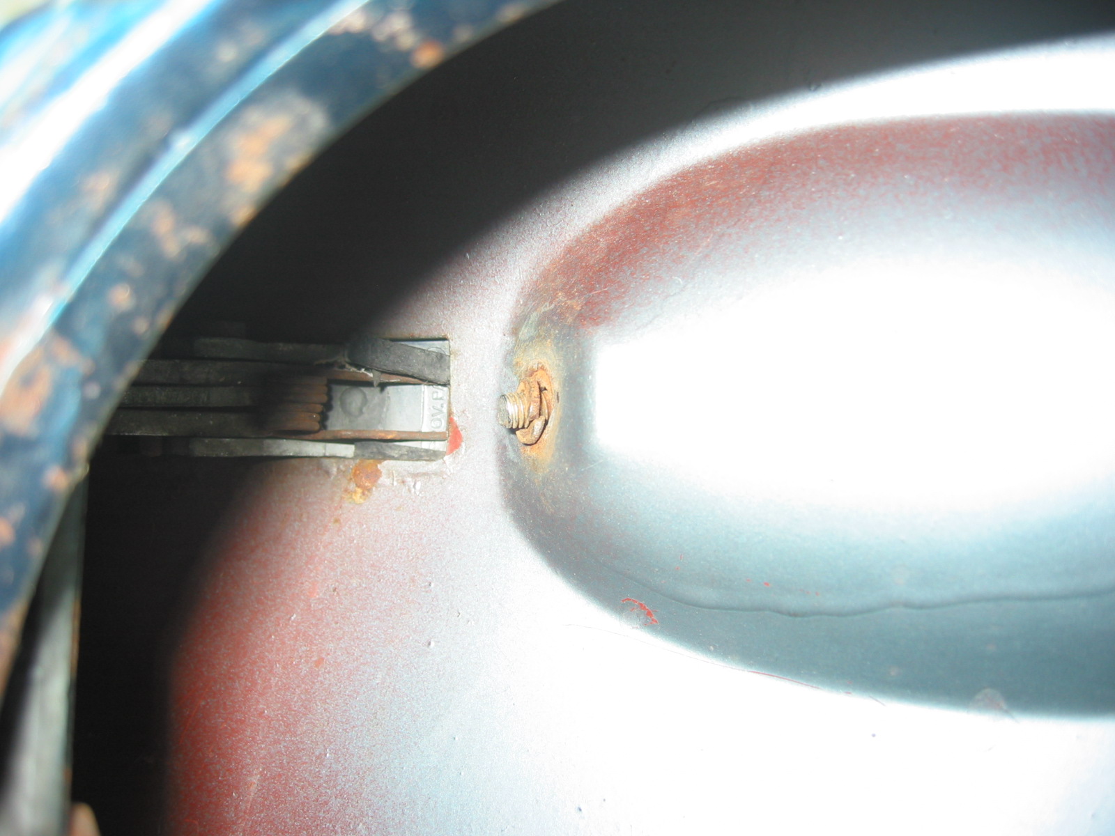
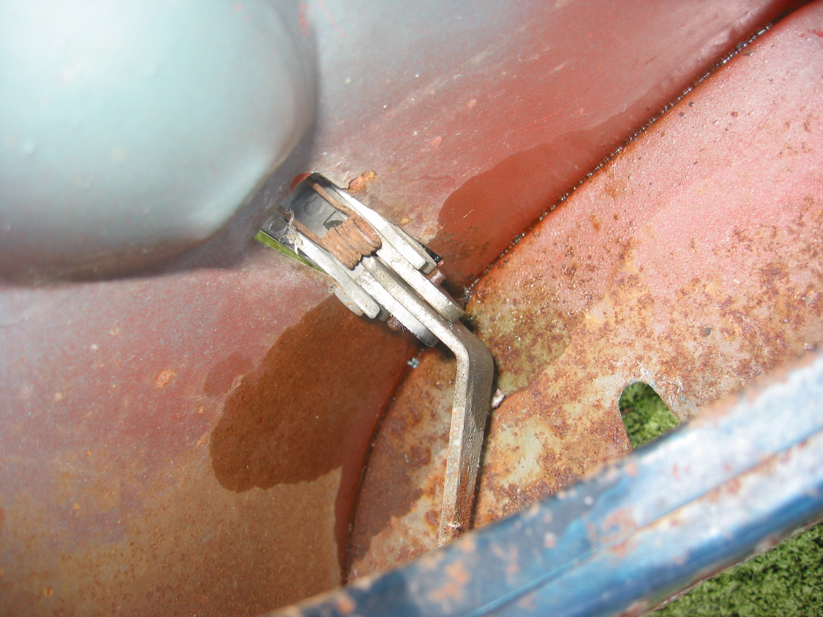
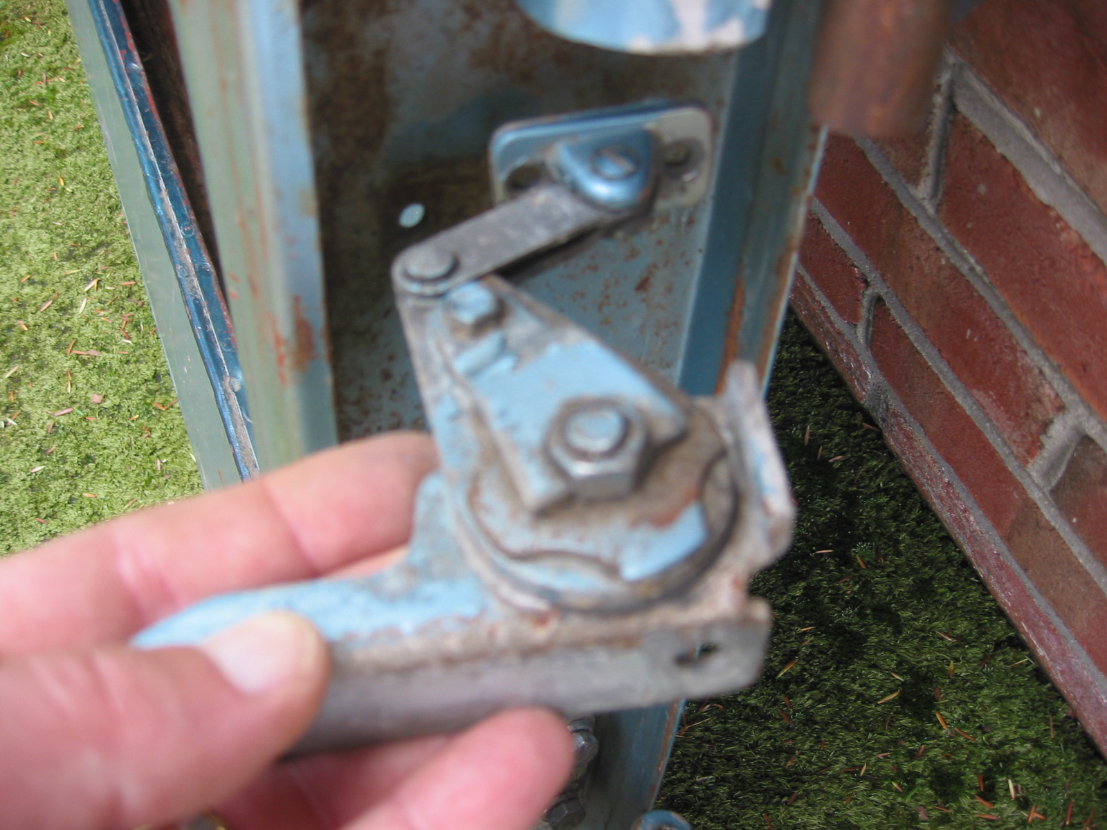
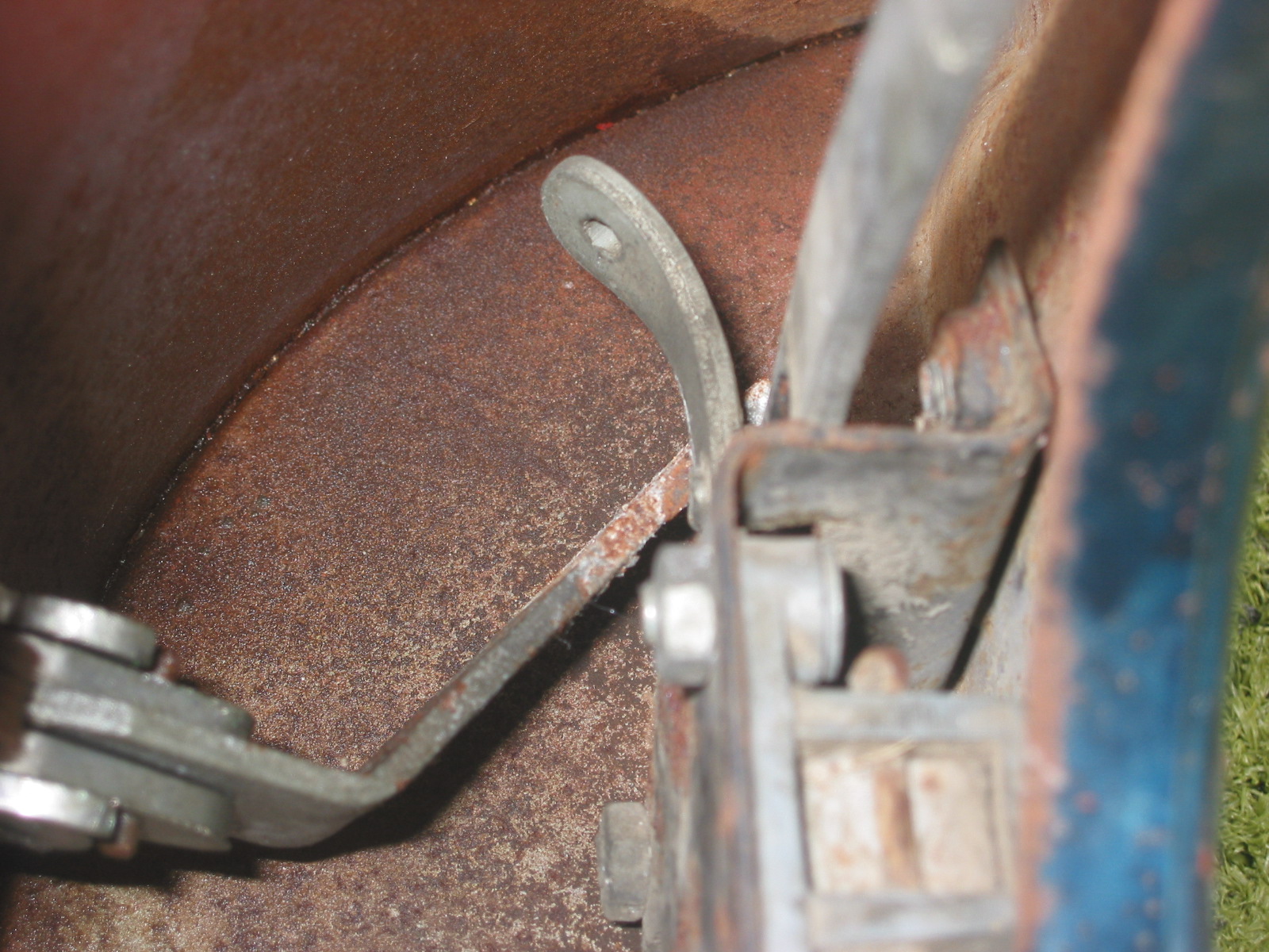
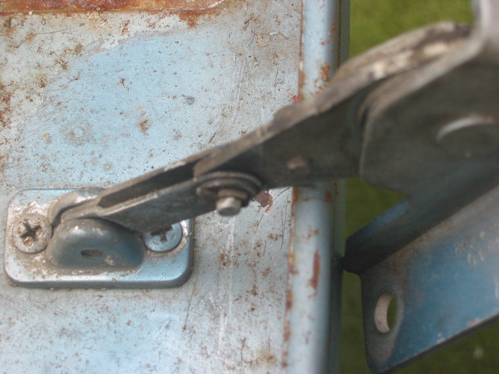
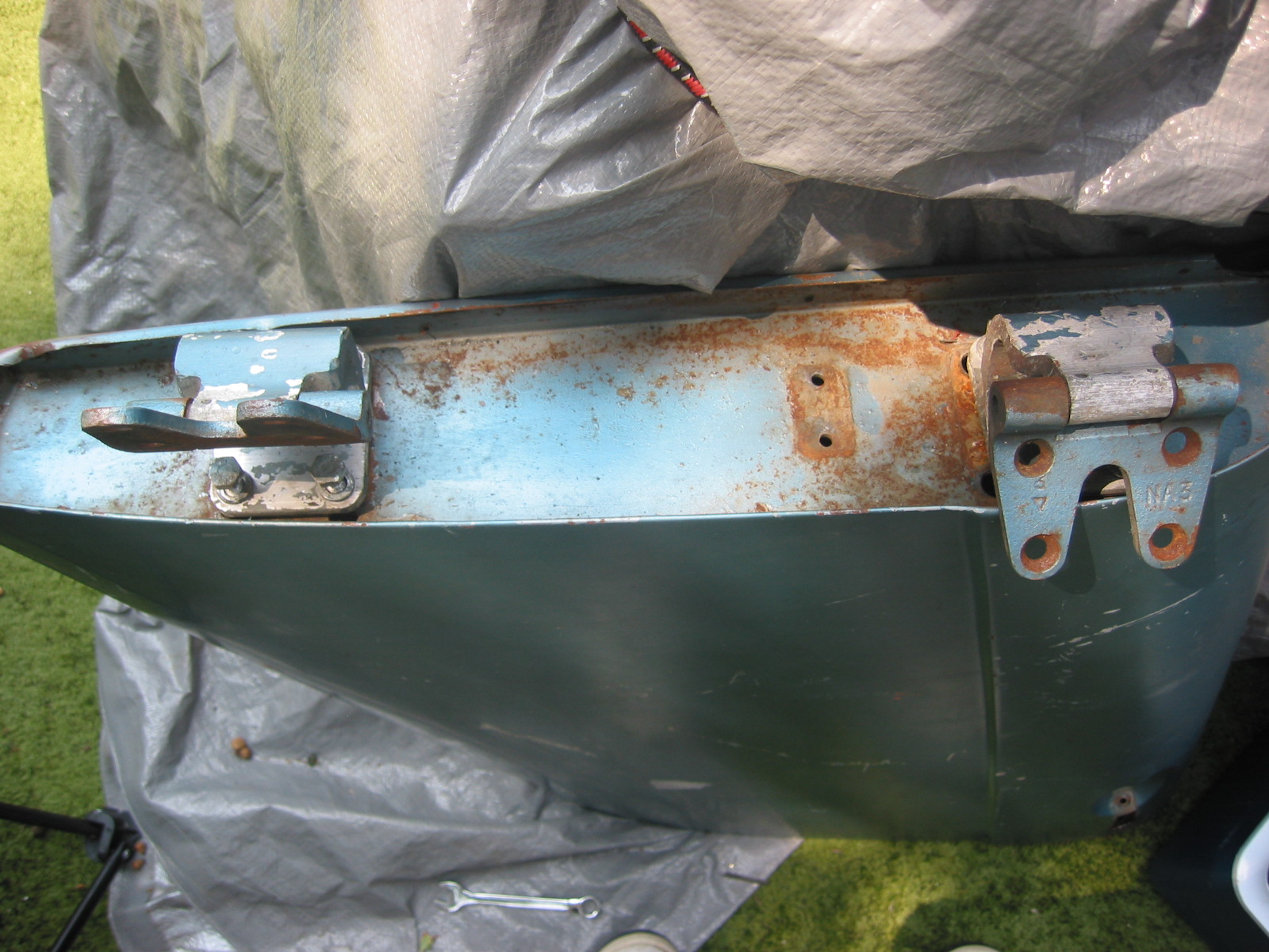
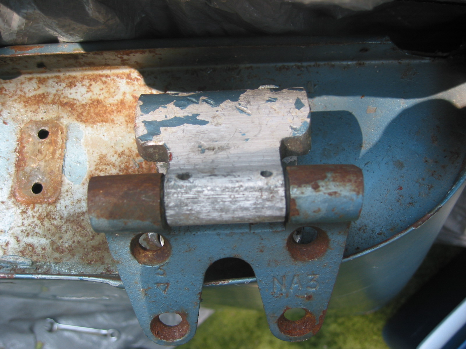
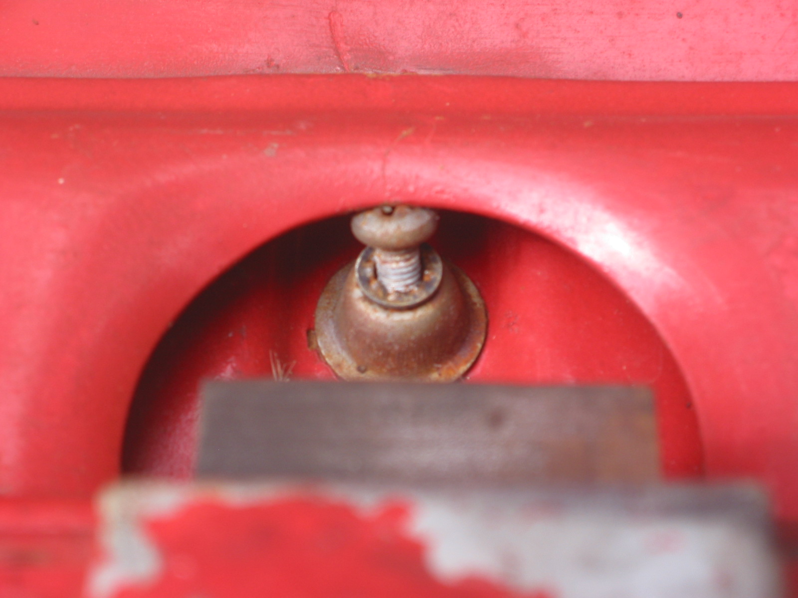
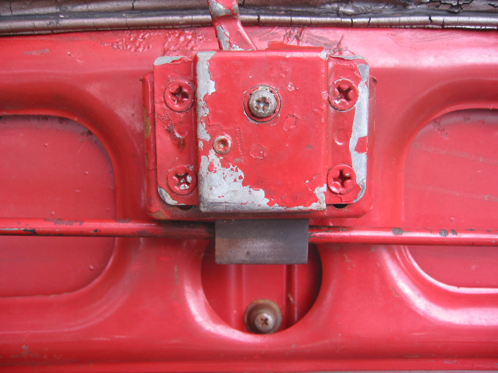
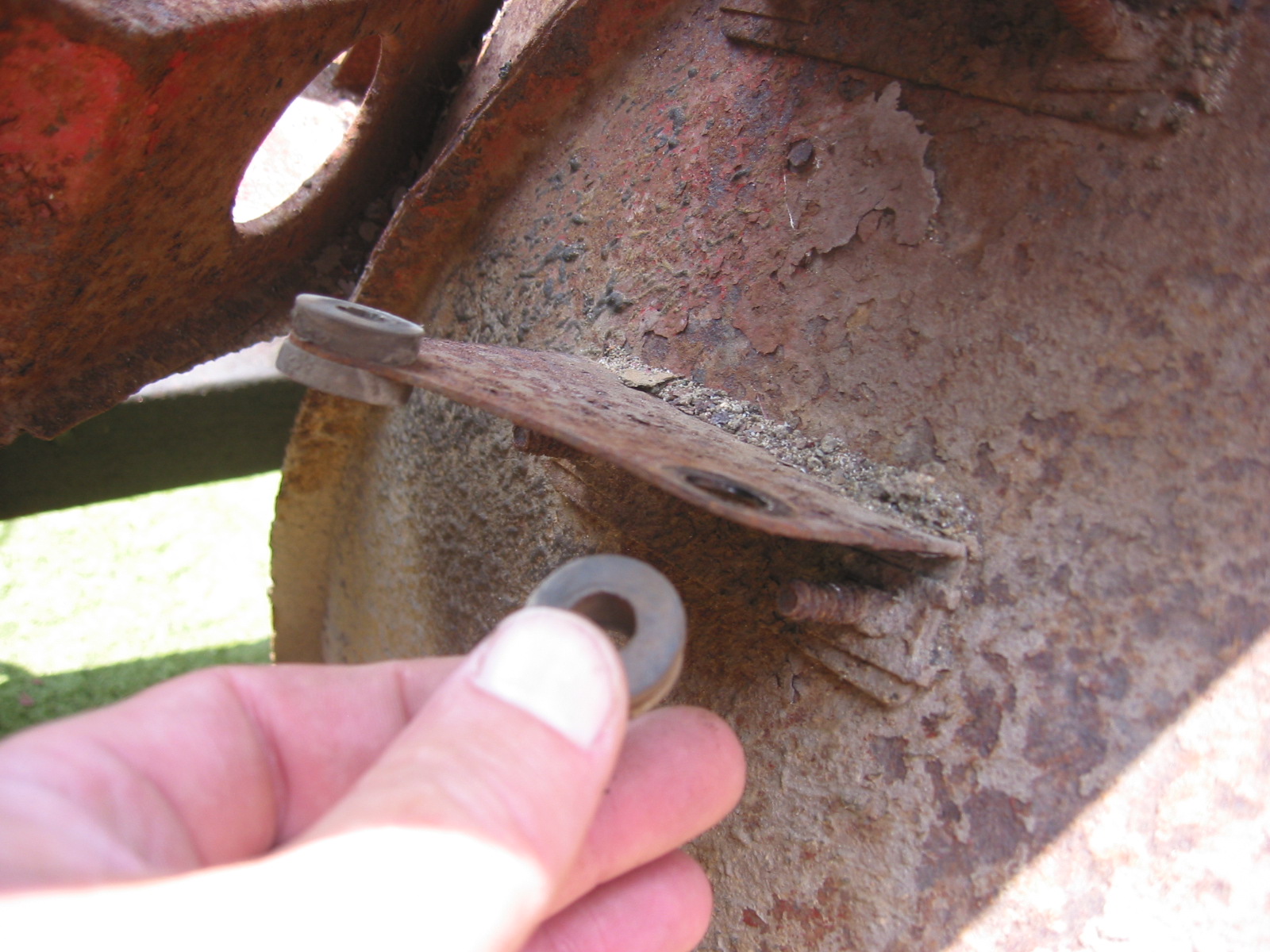
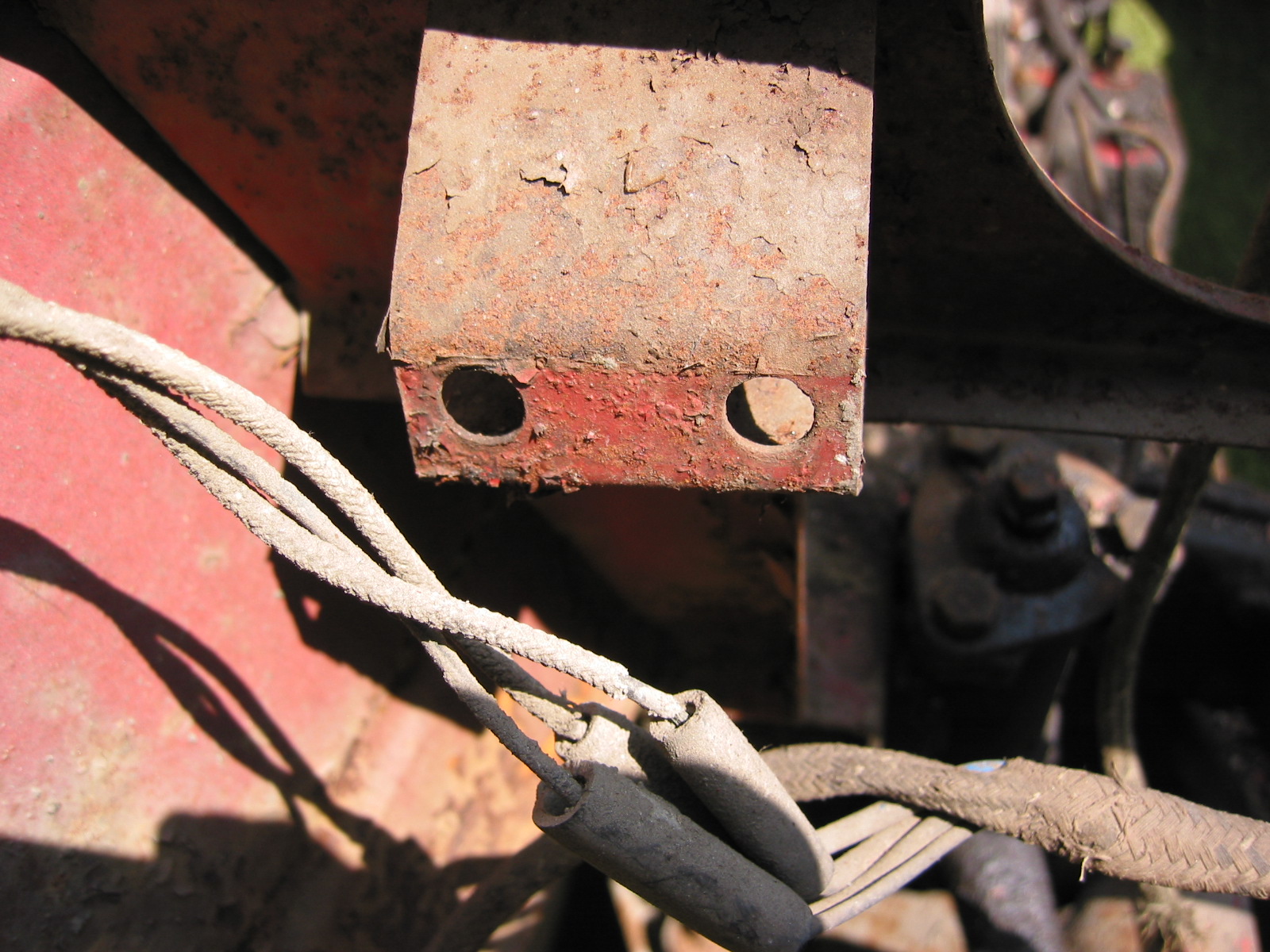
Fastened both tapped plates that secure the rear wings to the superstructure to the body temporarily. They may not be in the right location.

Wing tapped bracket
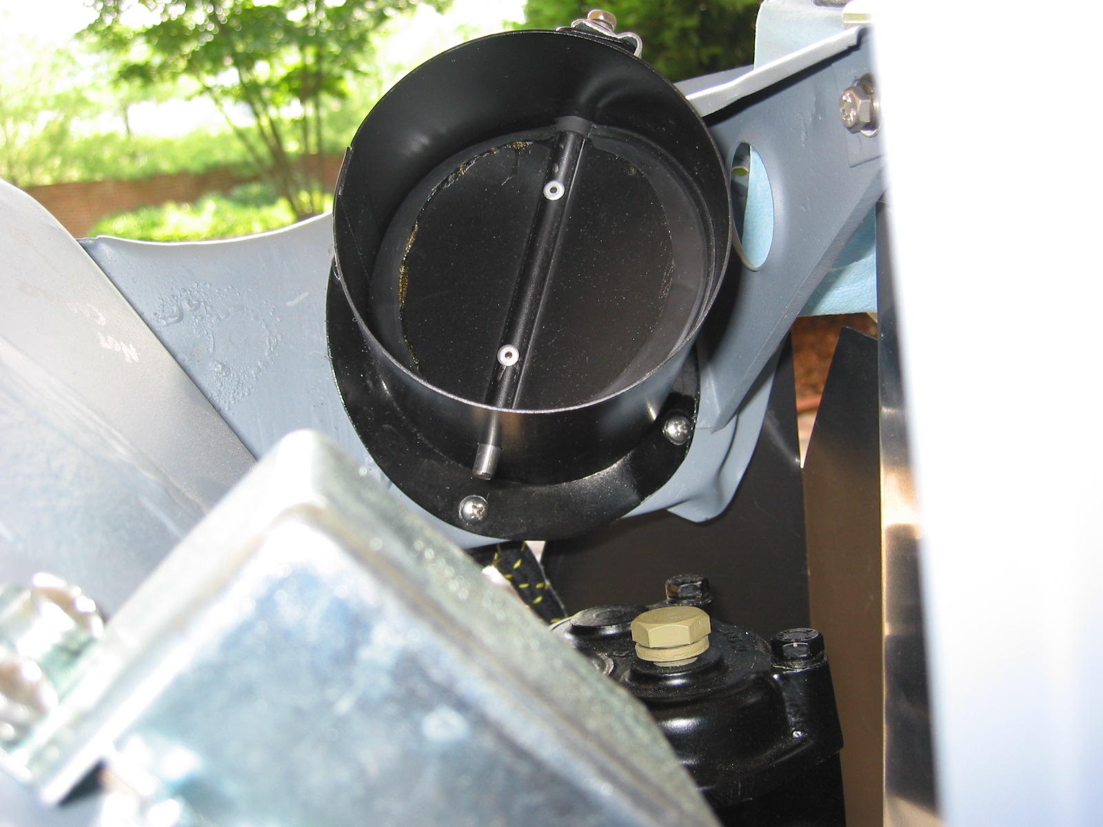
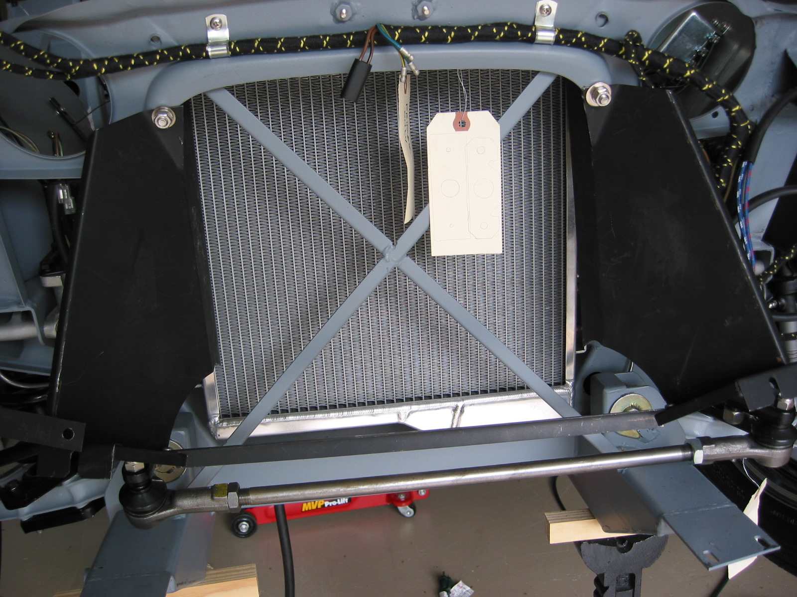
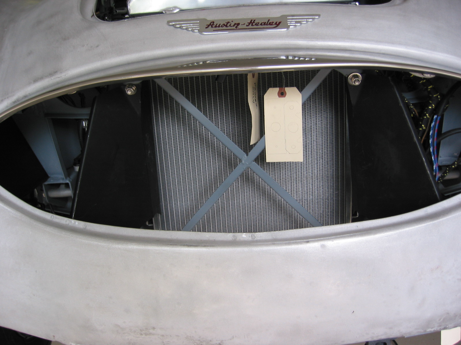
Air Control Assembly – Installed the front left air control assembly. It did not fit real well due to some bending done by Martin but after some convincing the job was accomplished.
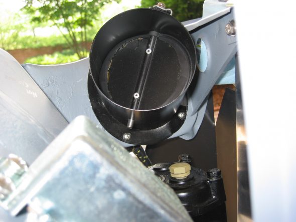
Fresh Air Assembly 1
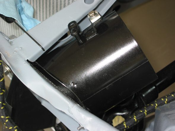
Fresh Air Assembly 2
Fresh Air Assembly 3
July 11, 2004
Heater Installation
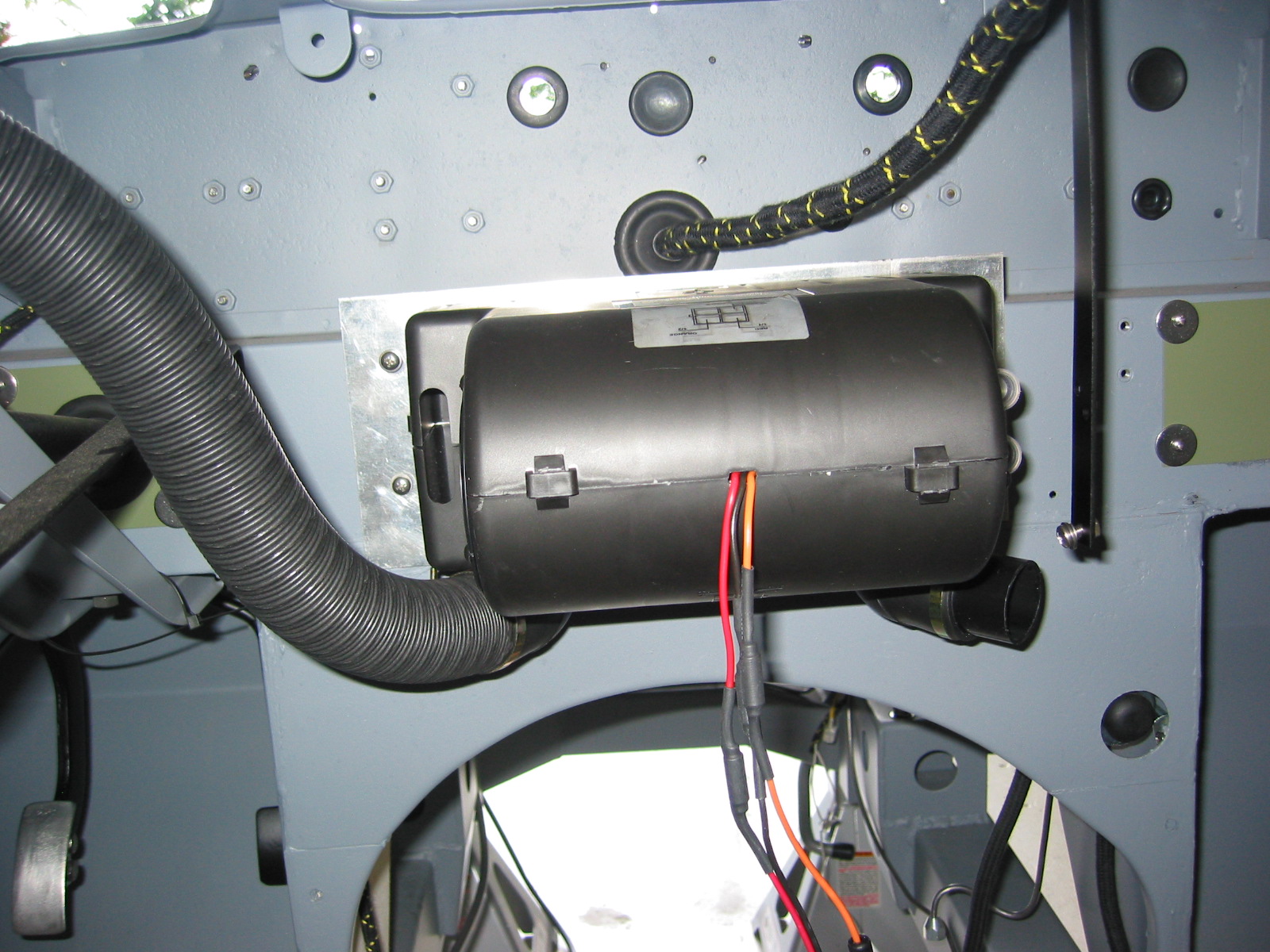
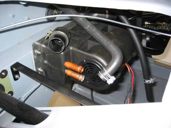
I purchased a modern replacement for the original Smiths Heater from Cape International. The heater is basically the same footprint, but it incorporates the fan blower making the original fan blower extraneous or irrelevant. The provided mounting plate to the cold air box was installed upside down and backwards which threw me for a minute. After reversing the plated the heater installed nicely using the four #10 x 1/2” original mounting locating screws.
New heater 1
Heater Cape Int 1

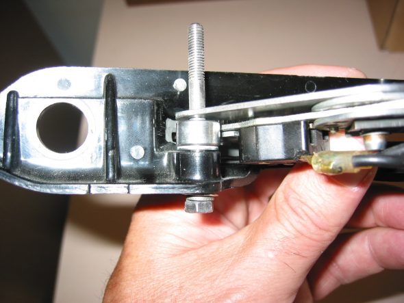
Heater Valve 4
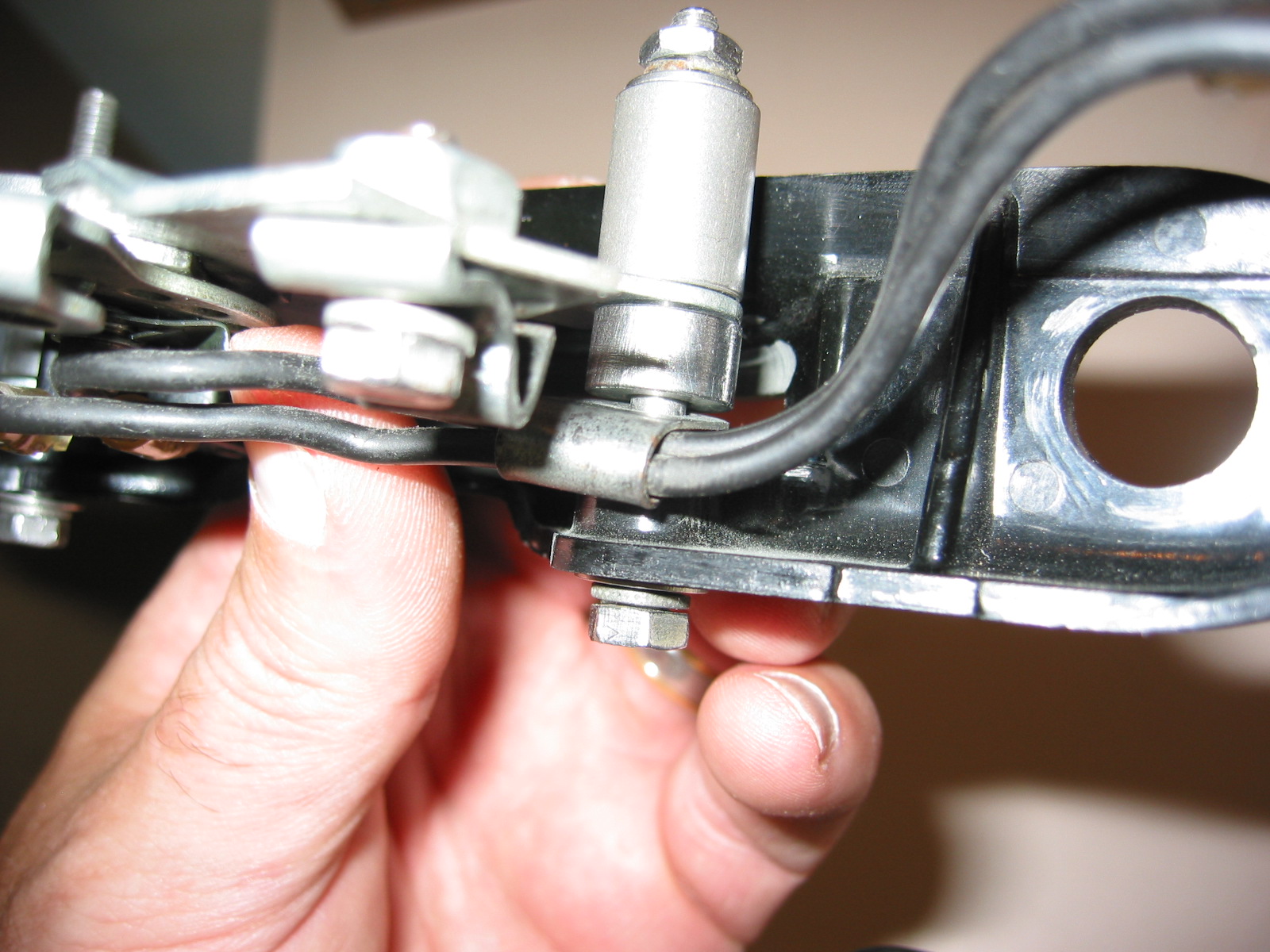
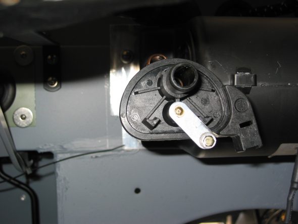
I drilled a slightly larger hole in the included water control valve control arm to permit the installation of a cable connector with tightening screw to secure the wire and cable sheath.
I could not figure out how to connect the water control valve in a way that would permit using the dash control slide knob as originally intended. Instead it works exactly in reverse. Oh well, small price to pay!
Replaced the original cable sheath and wire with a bicycle brake cable for smoother operation of the slide control to the water control valve. Worked nicely.
Heater Valve 3
Heater Valve 5
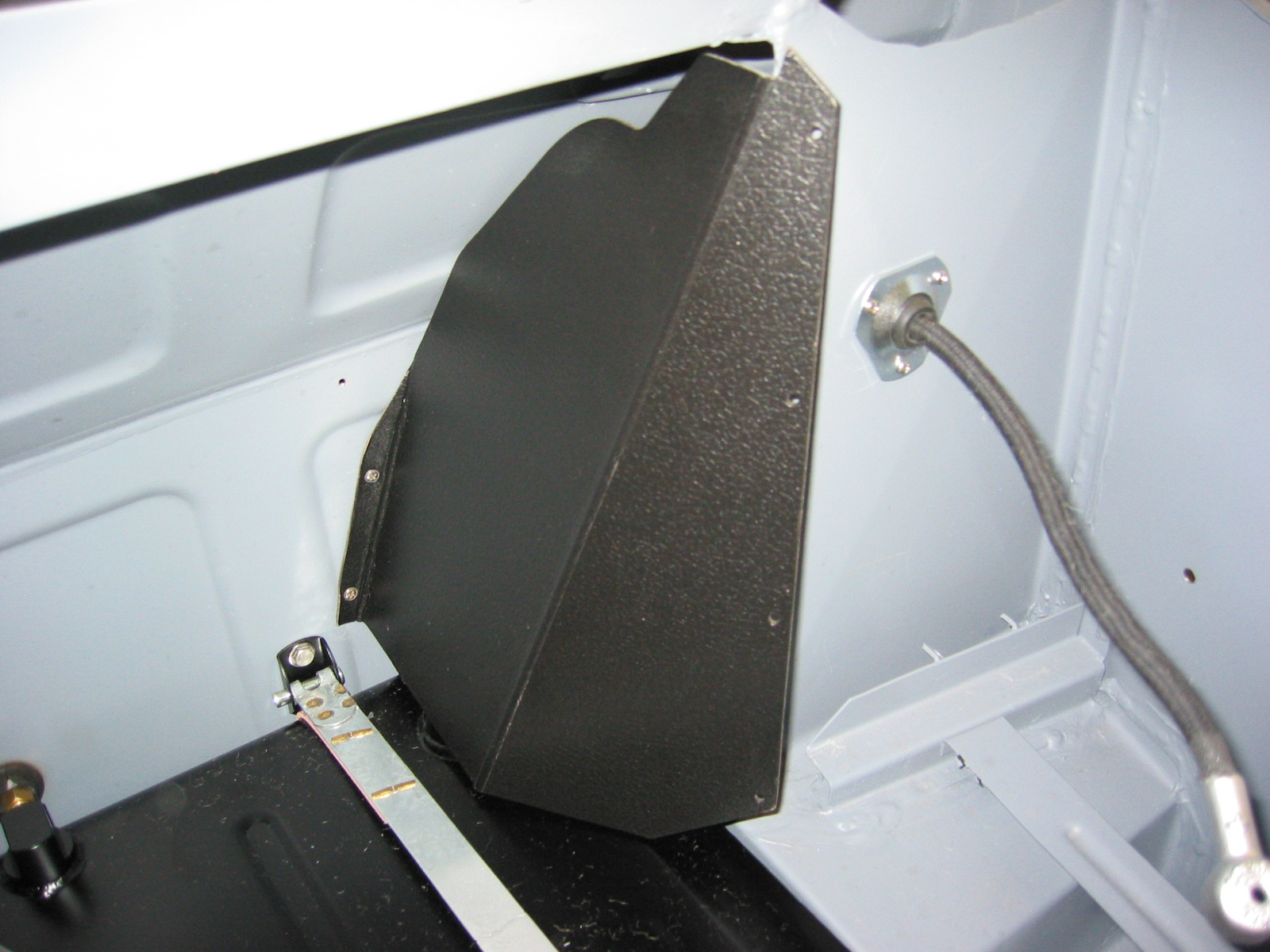
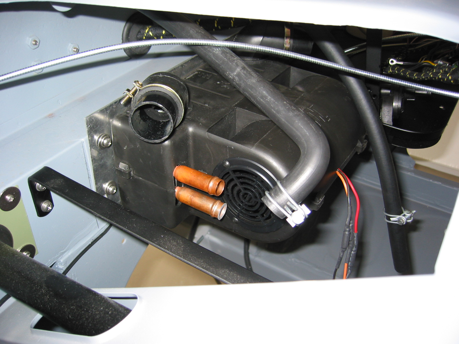
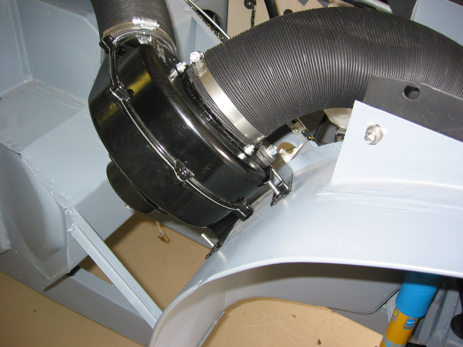
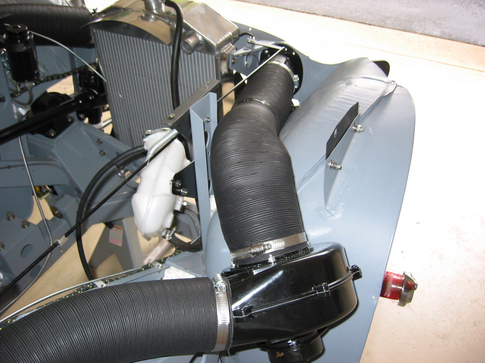
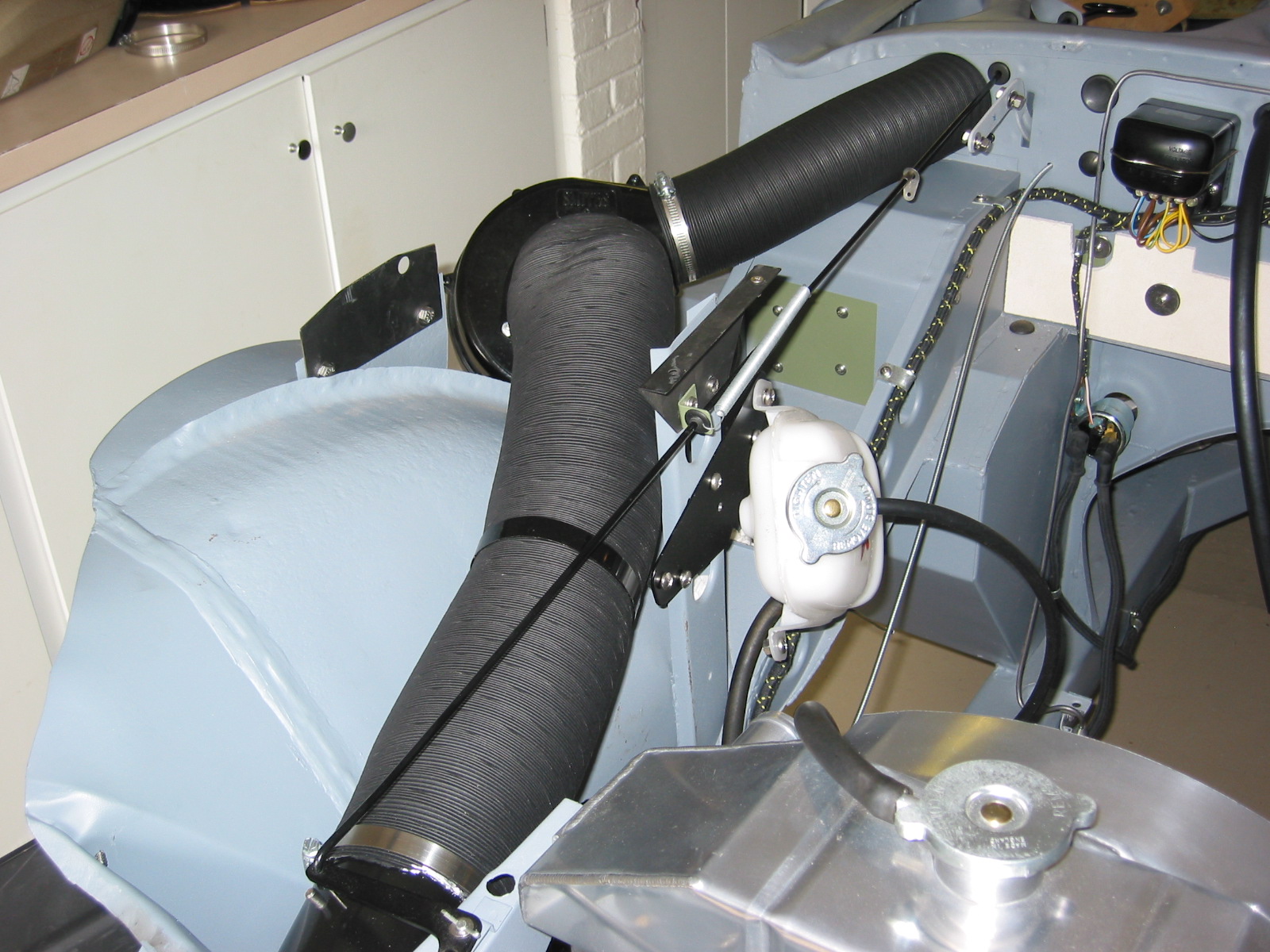
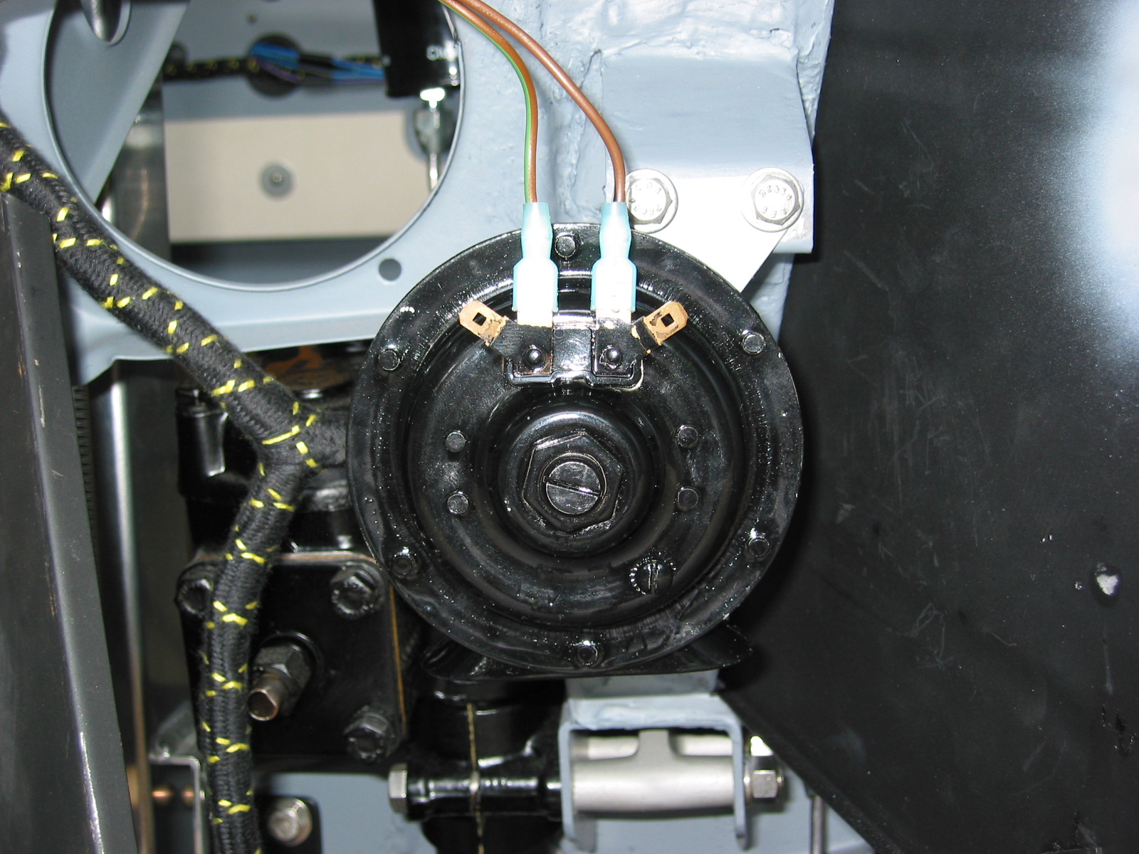
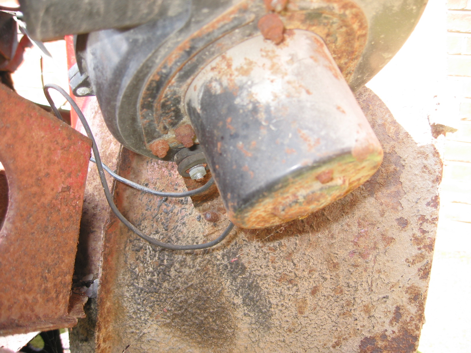
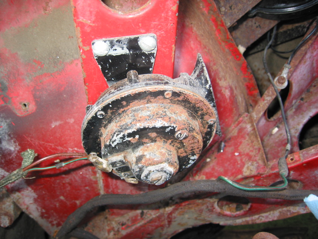
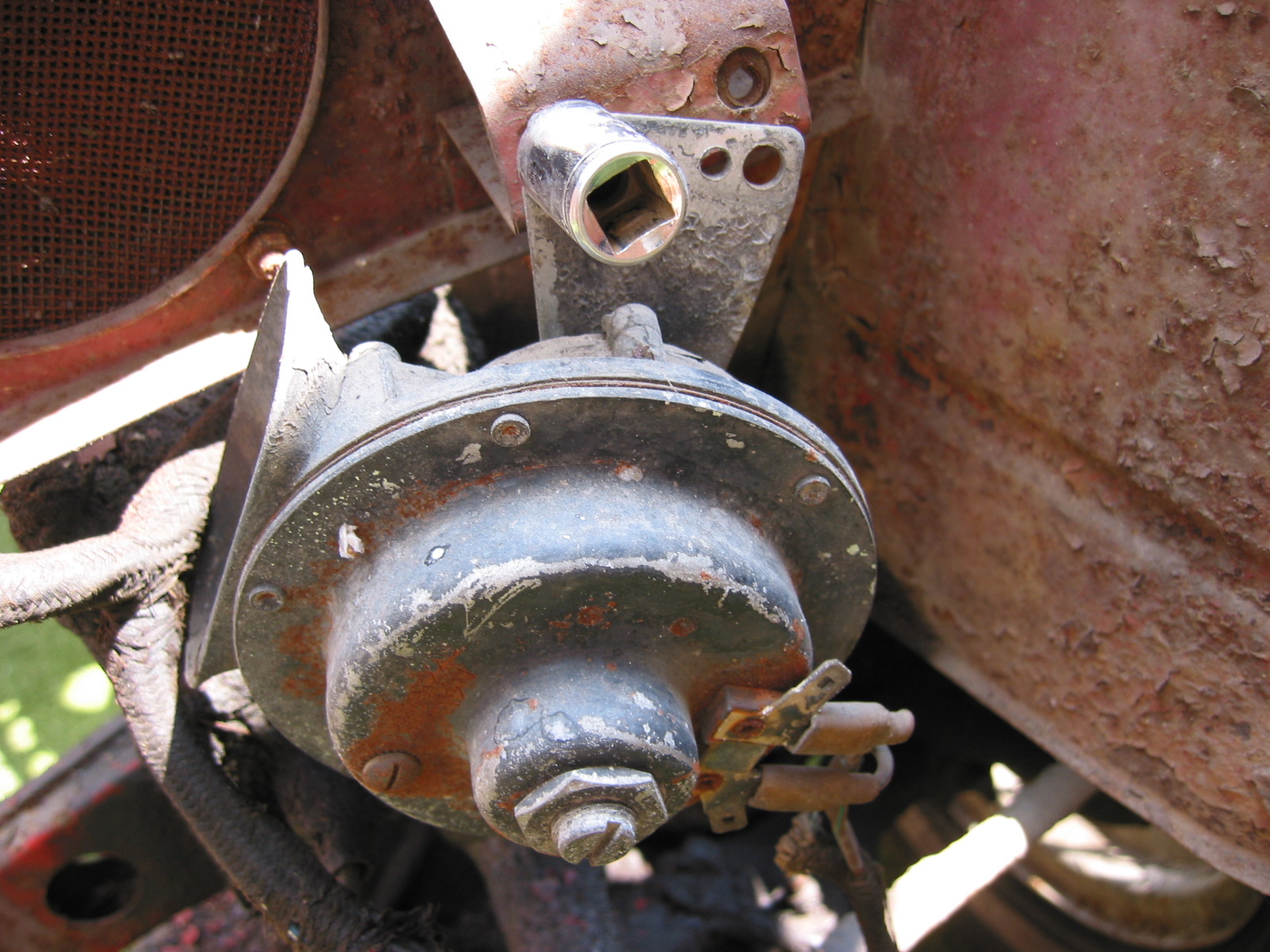
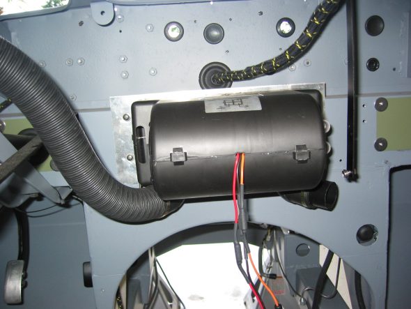
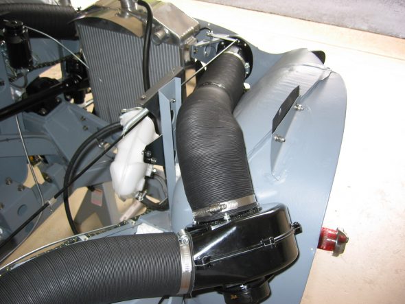
I received a new Smiths heater blower from Hemphills that proved to be a very nice replica of the old one. I installed a the new blower on the fender superstructure.
Blower and hose
Heater Blower Mounting

Heater Blower Hose 3 inch
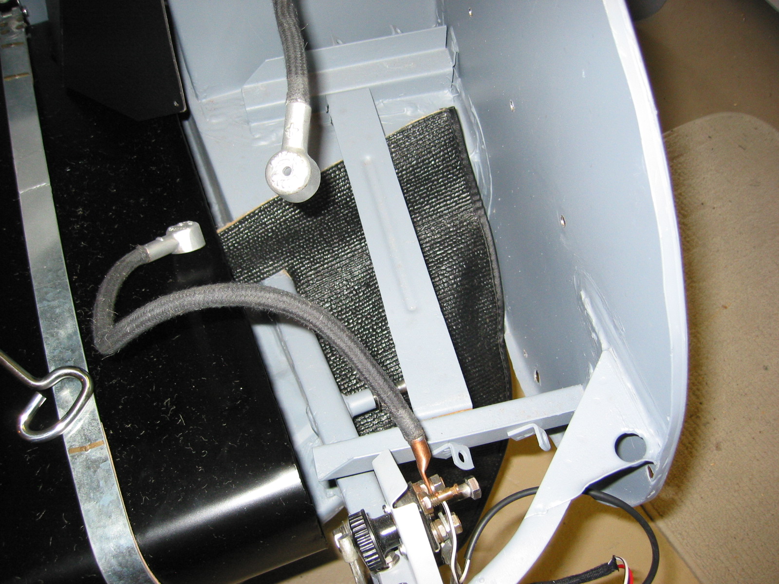
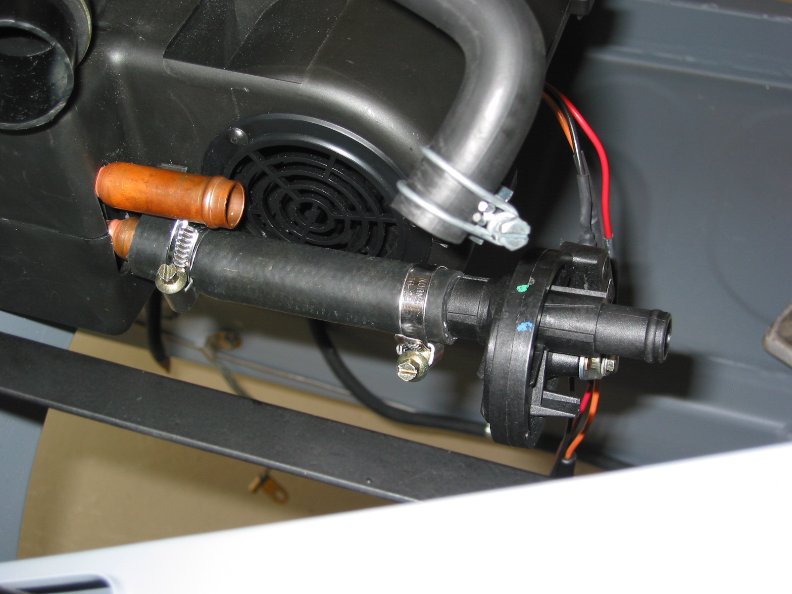
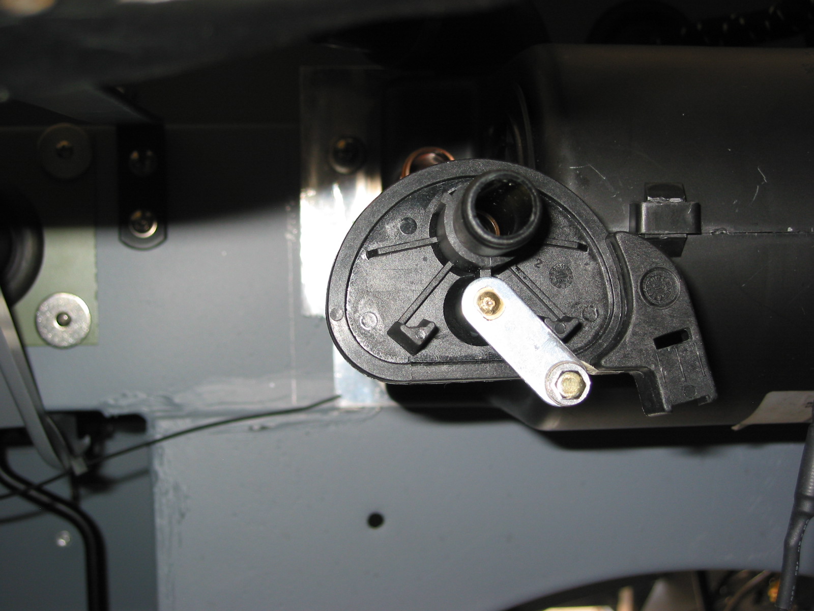
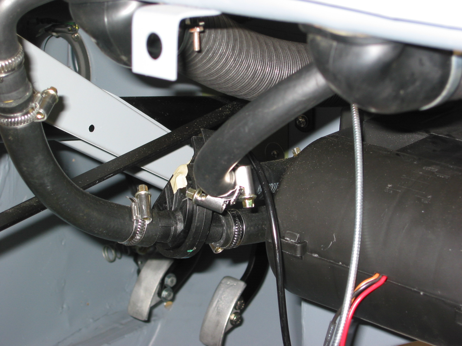
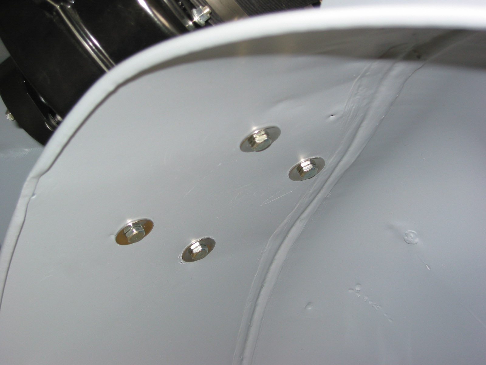
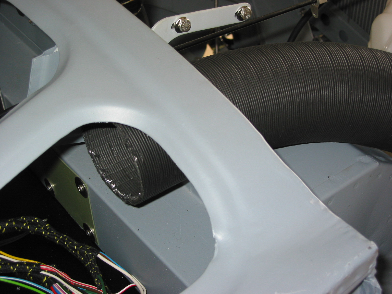
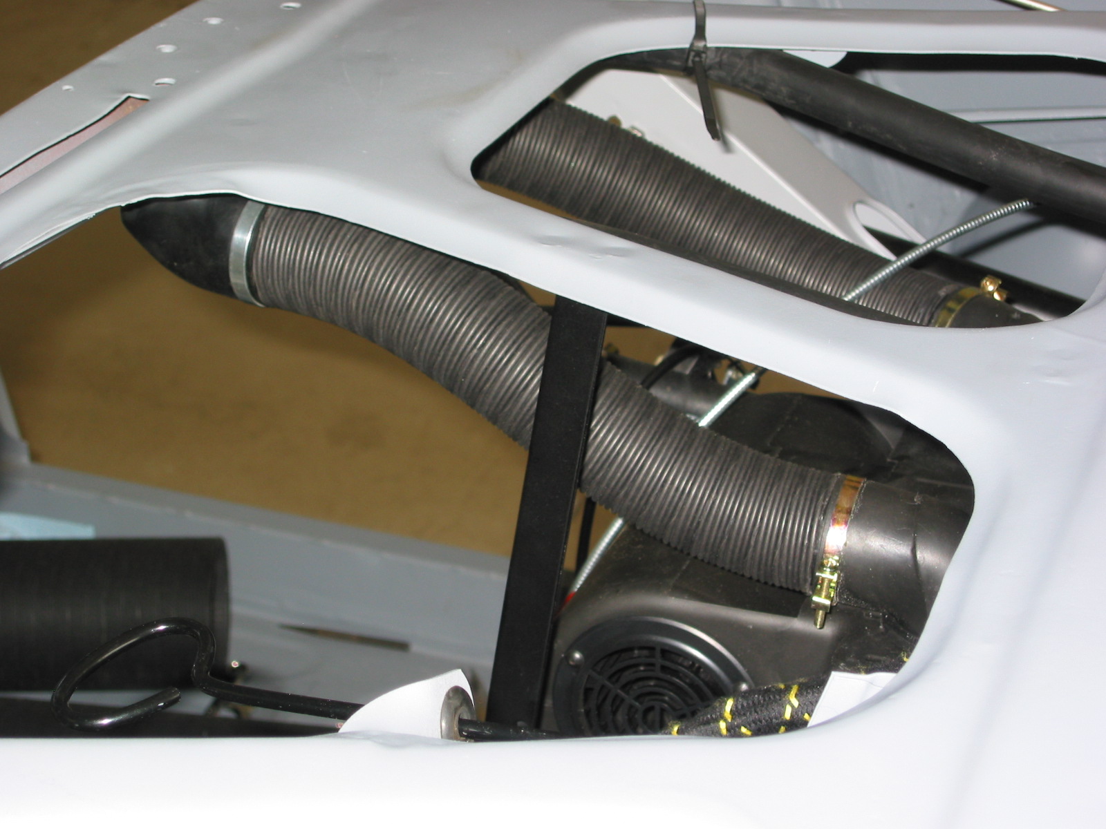
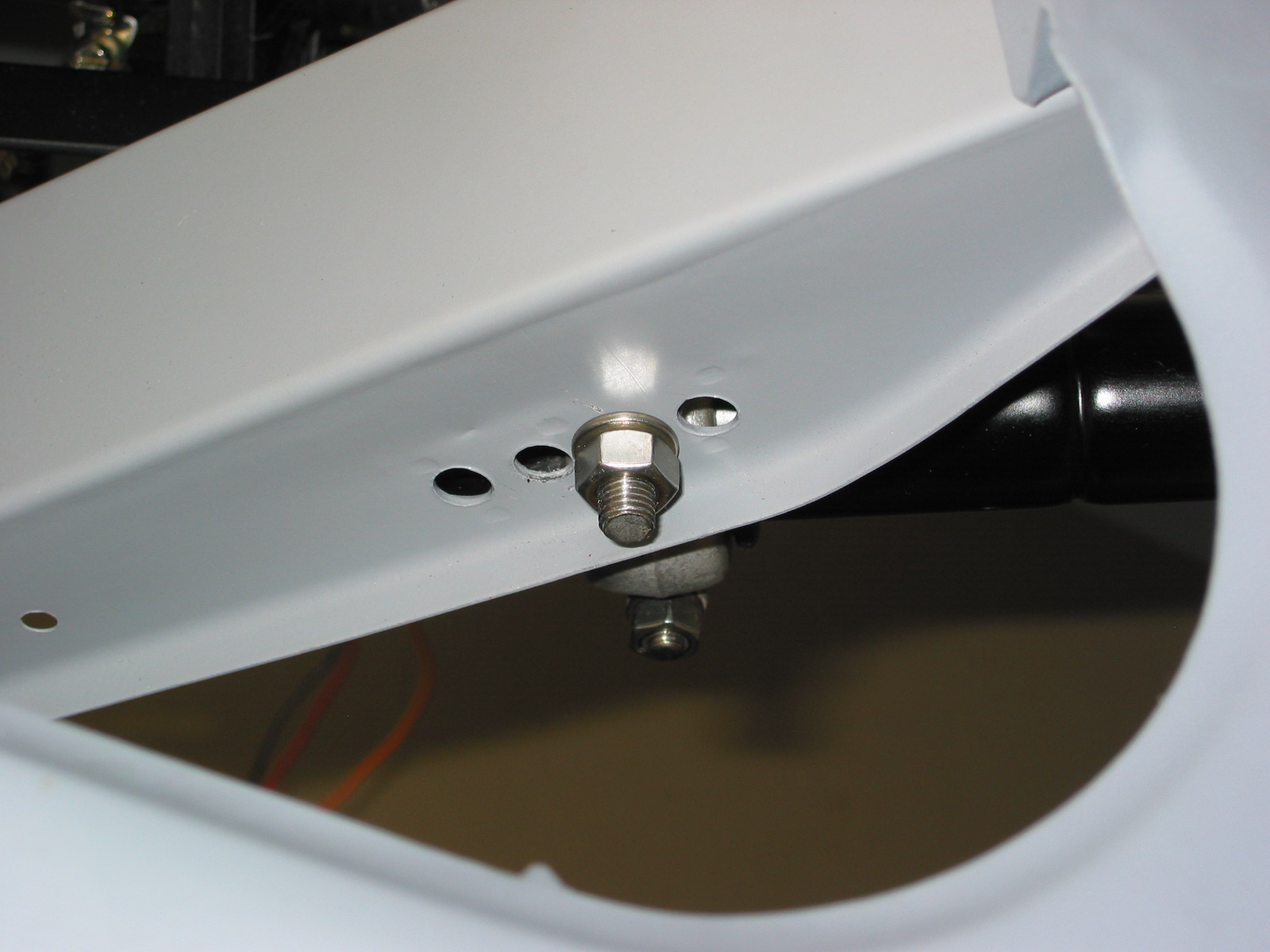
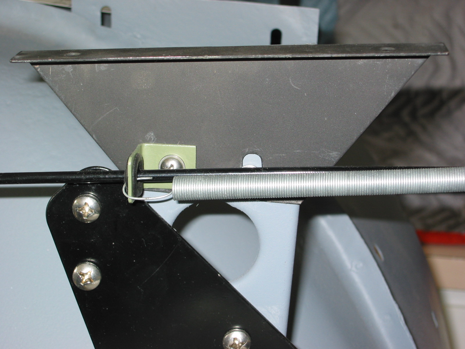
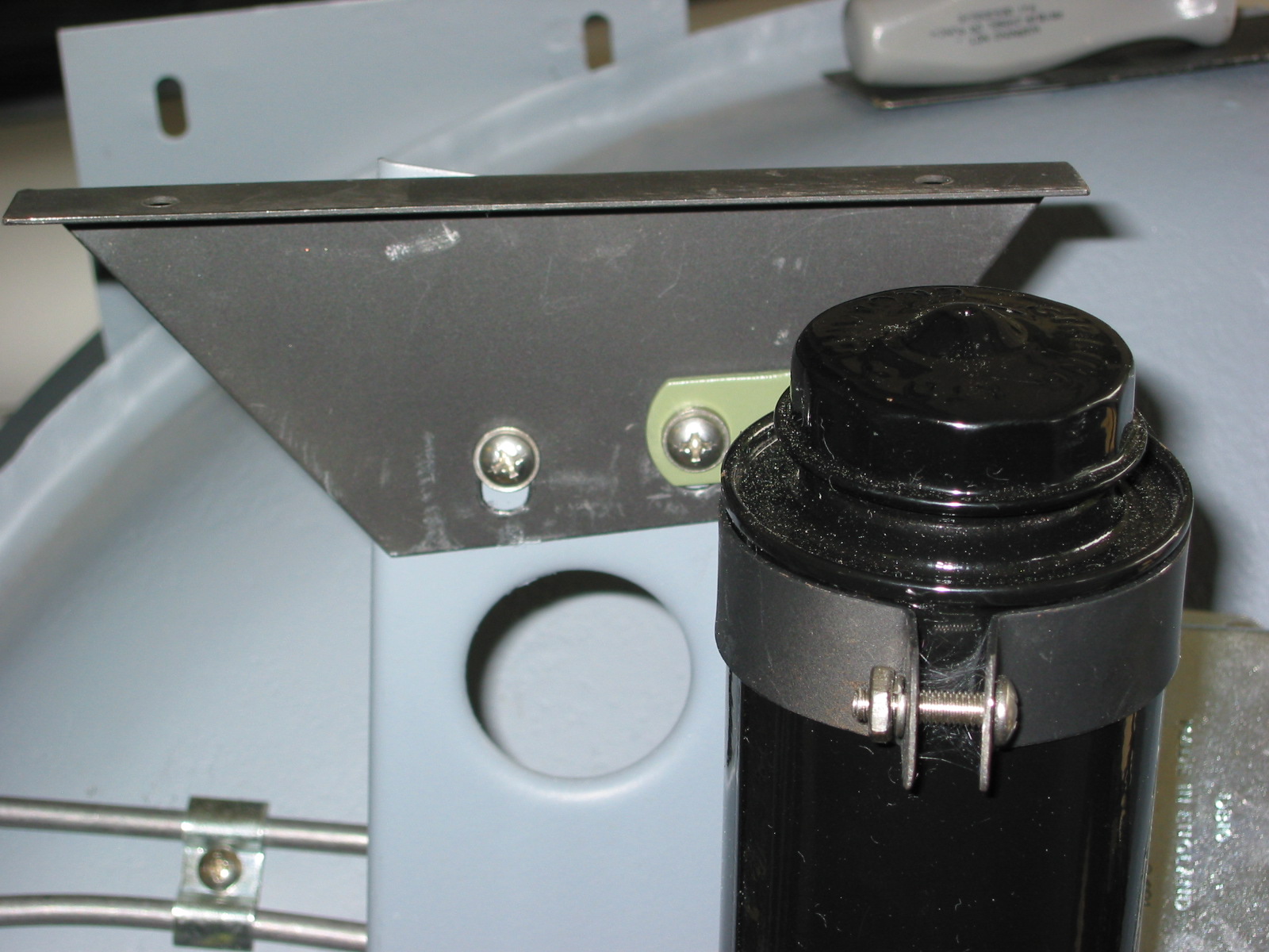
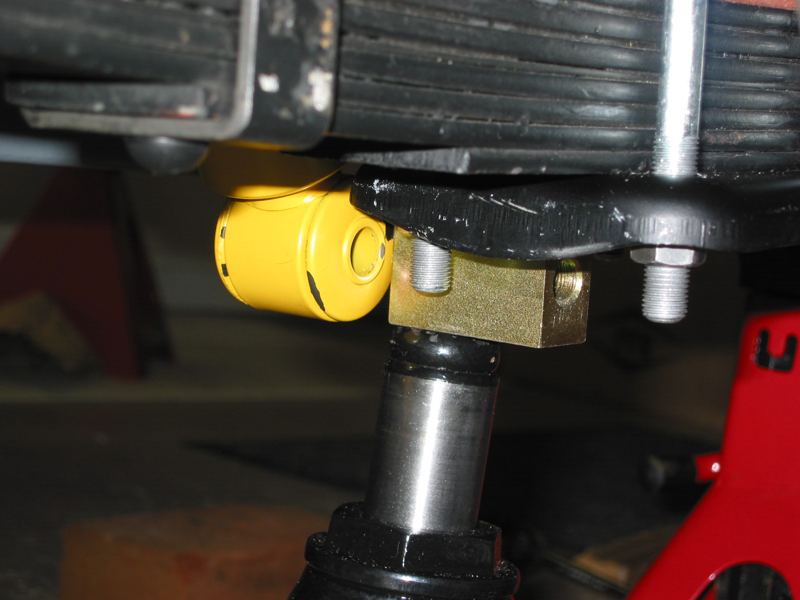
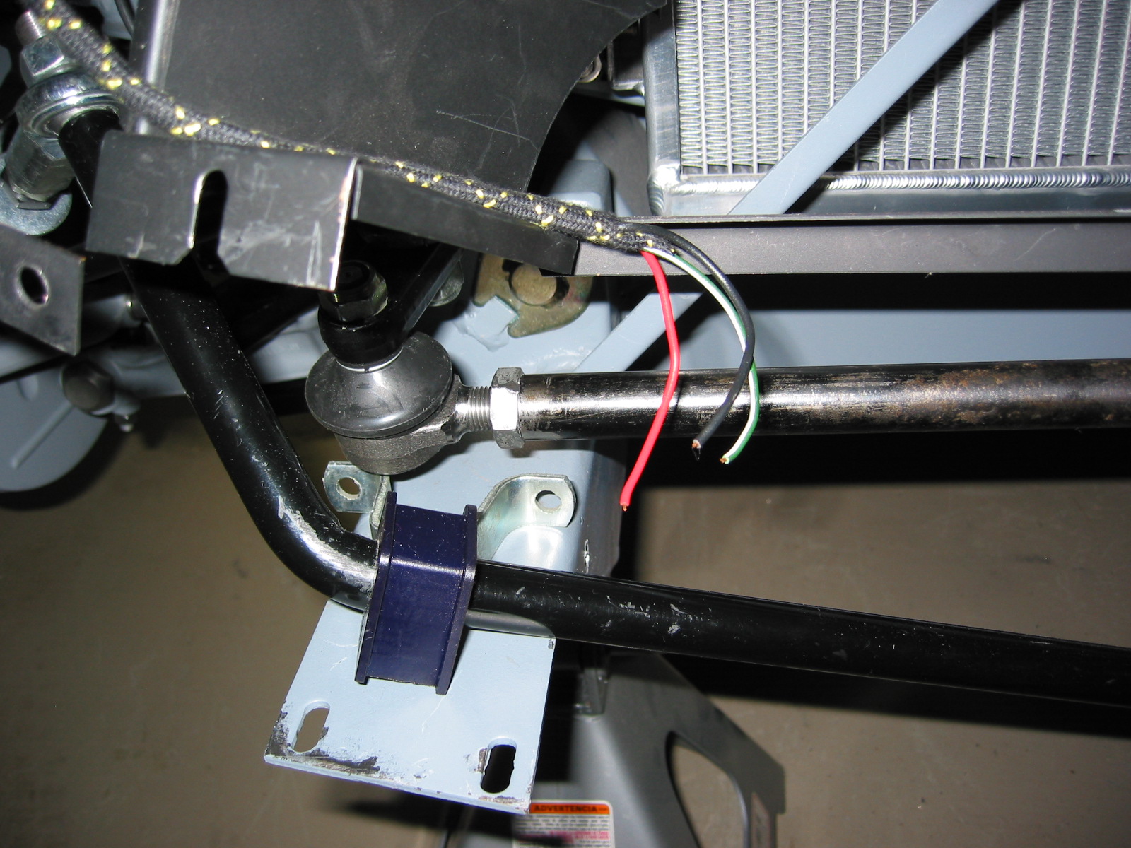
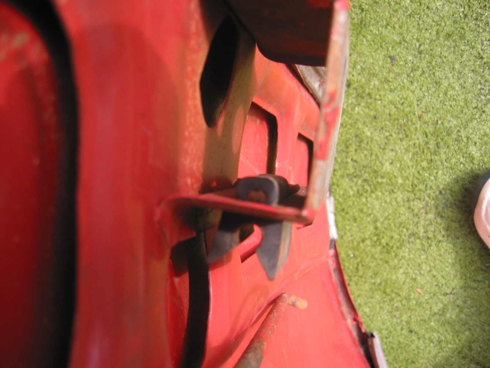
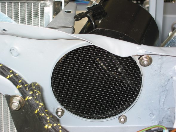
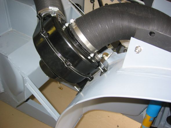
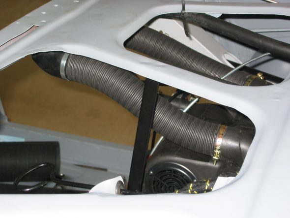
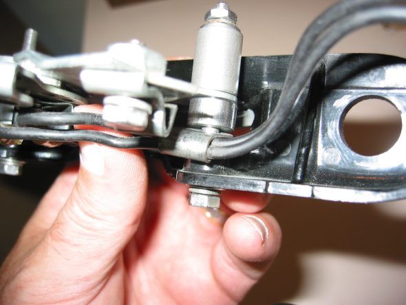
The new blower will now be used to “push” cold air into the passenger side of the interior. I purchased a new air control assembly typically used on the left side of the car. I cut off the mounting flange and inserted it into the ait tube.The right hand knob on the heater panel that used to control the heater can now be used to control fresh air into the cockpit on the passenger side.The cable clamp must be located just as in the photo accessible below the car to get the maximum movement on the air control valve. I need to get some nylon mesh to screen the front air intake. This will give a very “neat” and elegant installation. The cold air will empty just above the parcel shelf in the interior.
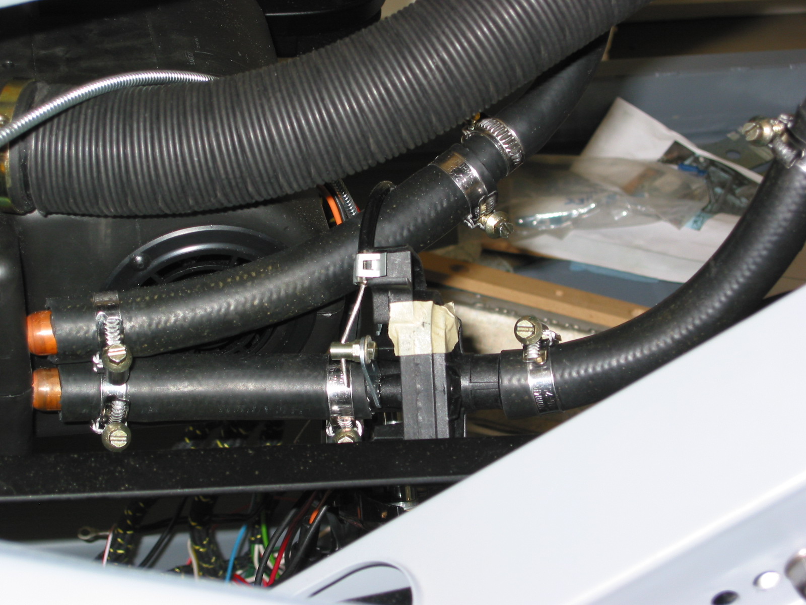
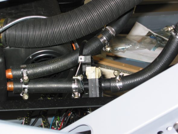
Heater Hoses

Heater Hose Assembly
Inverted Control Cable connections
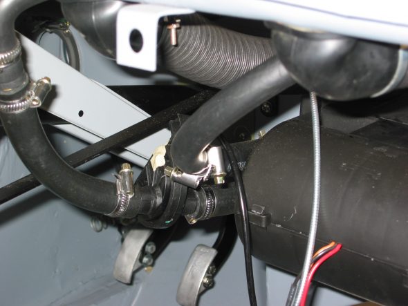
I used band hose clamps which cut into the duct hose so when I install the final time I will switch to the wire clamps as used on the car originally. The 4” hose could be approximately 1” longer on final install and the 3” hose could be slightly shorter. I discovered that one needs to clamp the 3” hose to the blower before tightening the blower to the inner fender.
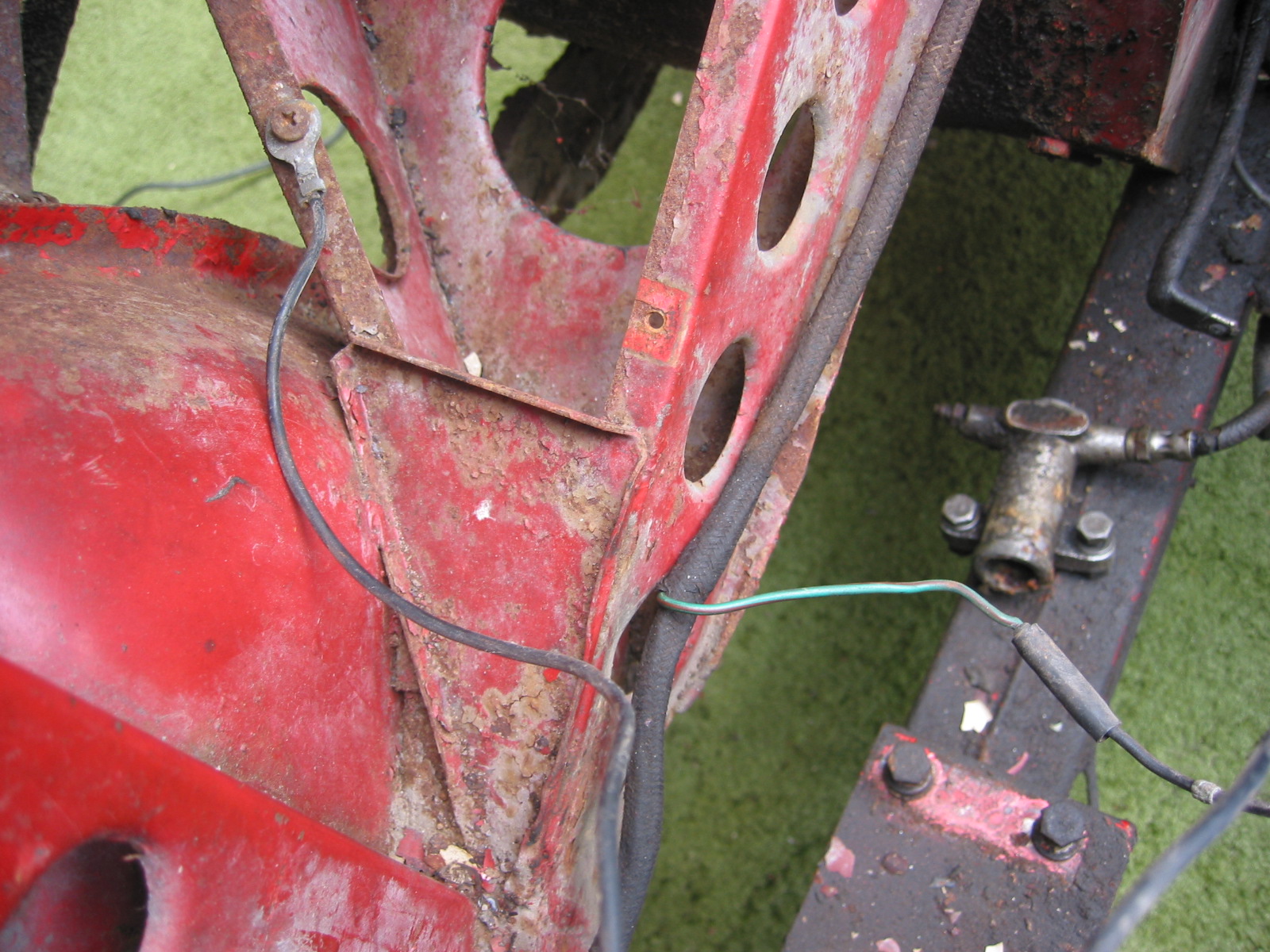
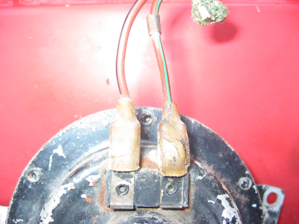
The wiring connections are used as originally fitted. Green and a green/brown wire connect to the two black wires on the dash slide control. The single green wire from the harness connects to the blower on the wheel arch. New wiring and a switch will be added to control the new two speed heater.
Cut the two demister hoses to length and installed them from the top of the heater to the dash superstructure.
Heater demister hoses
Heater demister hoses 2
Fascia Installation – Fit the fascia to the body. Mounts with four chrome screws and nuts at the corners. One additional screw mounts on the face of the fascia through to the body in the top center. Another locates the brace from the firewall. Upon installation I discovered that the steering column contacted the bottom of the chrome ring surround in the fascia so I moved the column mounting bracket to a higher securing hole on the column brace.

Steering wheel new setting
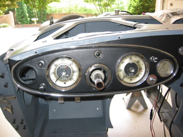
Fascia Instruments
Heater Control Panel
Filed the edges of the control panel very carefully and improved the fit to the fascia considerably.
Heater control 1
Heater control 2
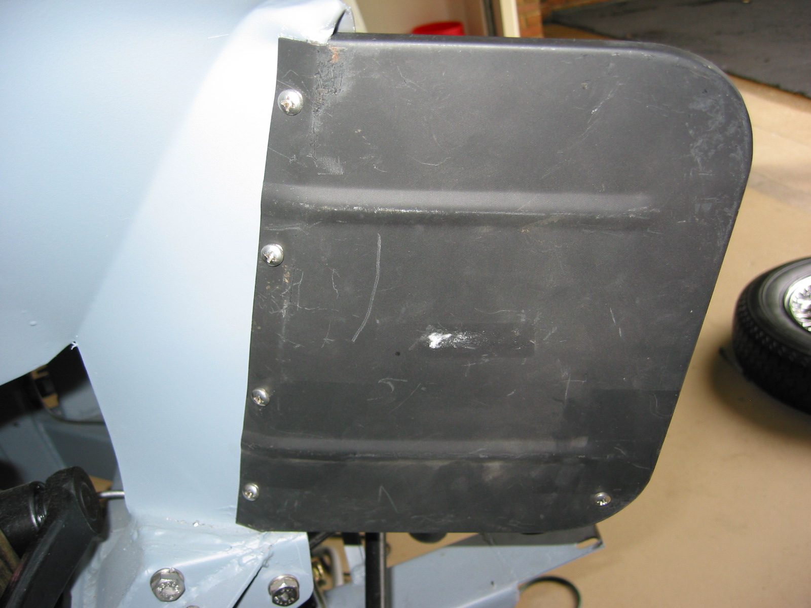
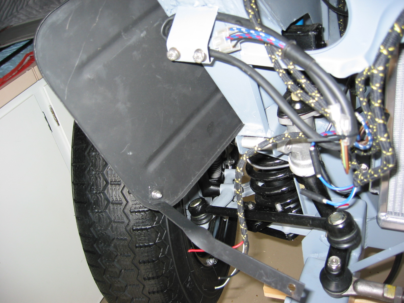
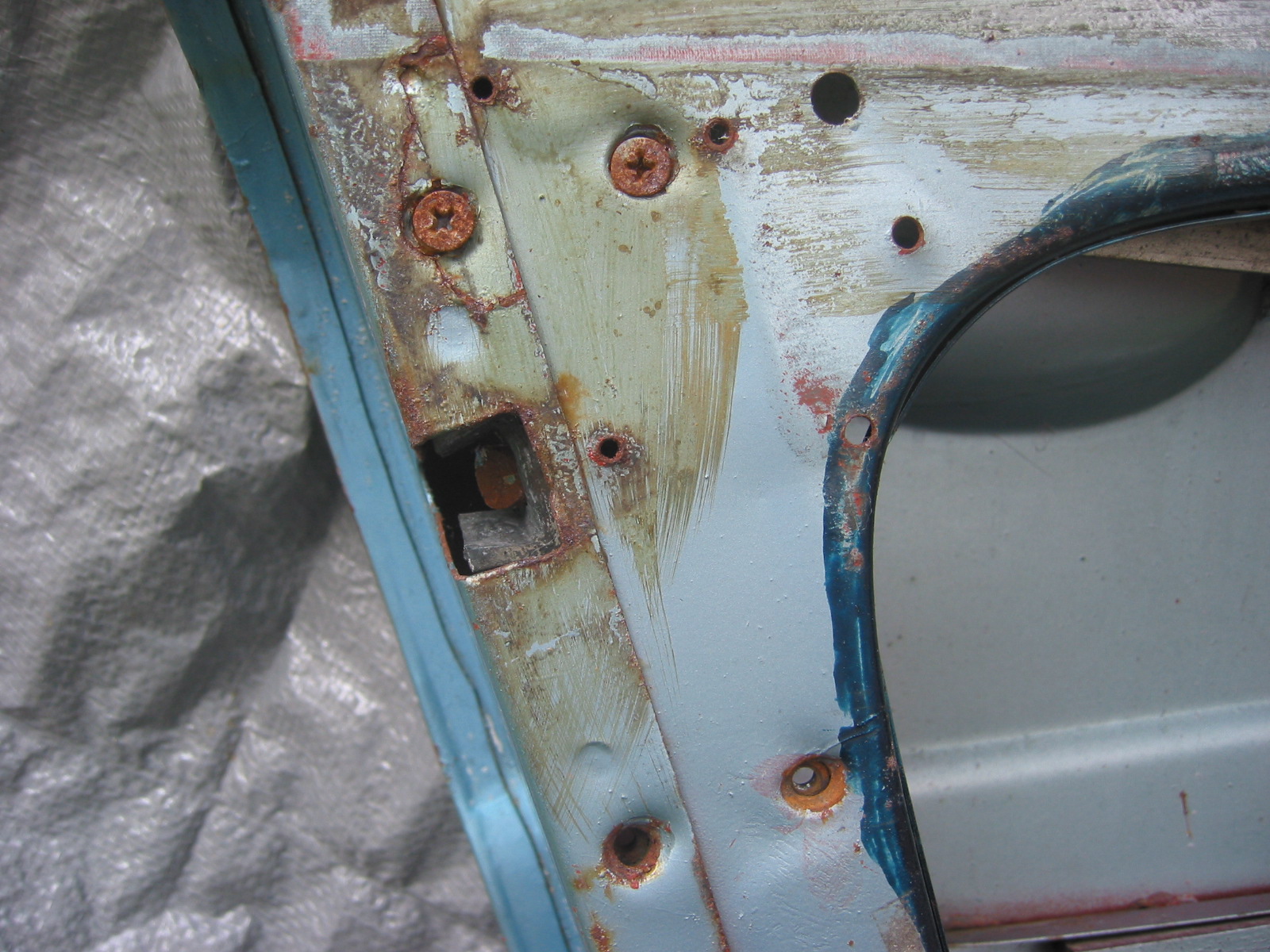
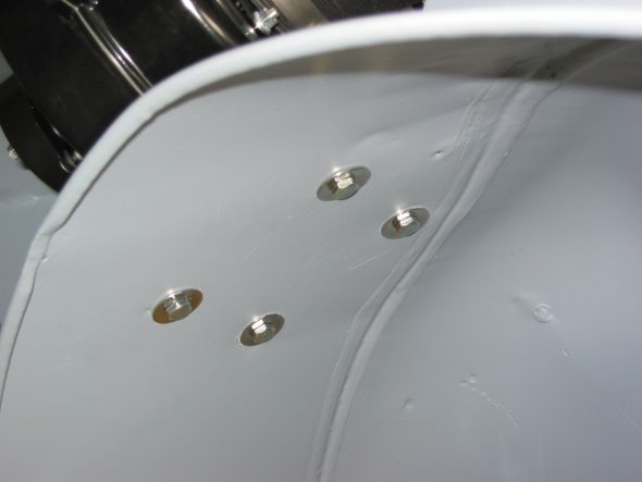
Blanking Plate – Installed the blanking plate on the right side of the car to cover the master cylinder mounting holes for a RHD car. Used #8 1/2” sheet metal screws into four J nut fasteners. The original plate had tar paper on the back side to seal and insulate, so I will need to do something similar on final install, after the final paint is applied.
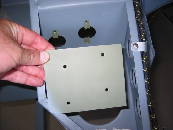
Blanking plate install 2

Blanking Plate install 3
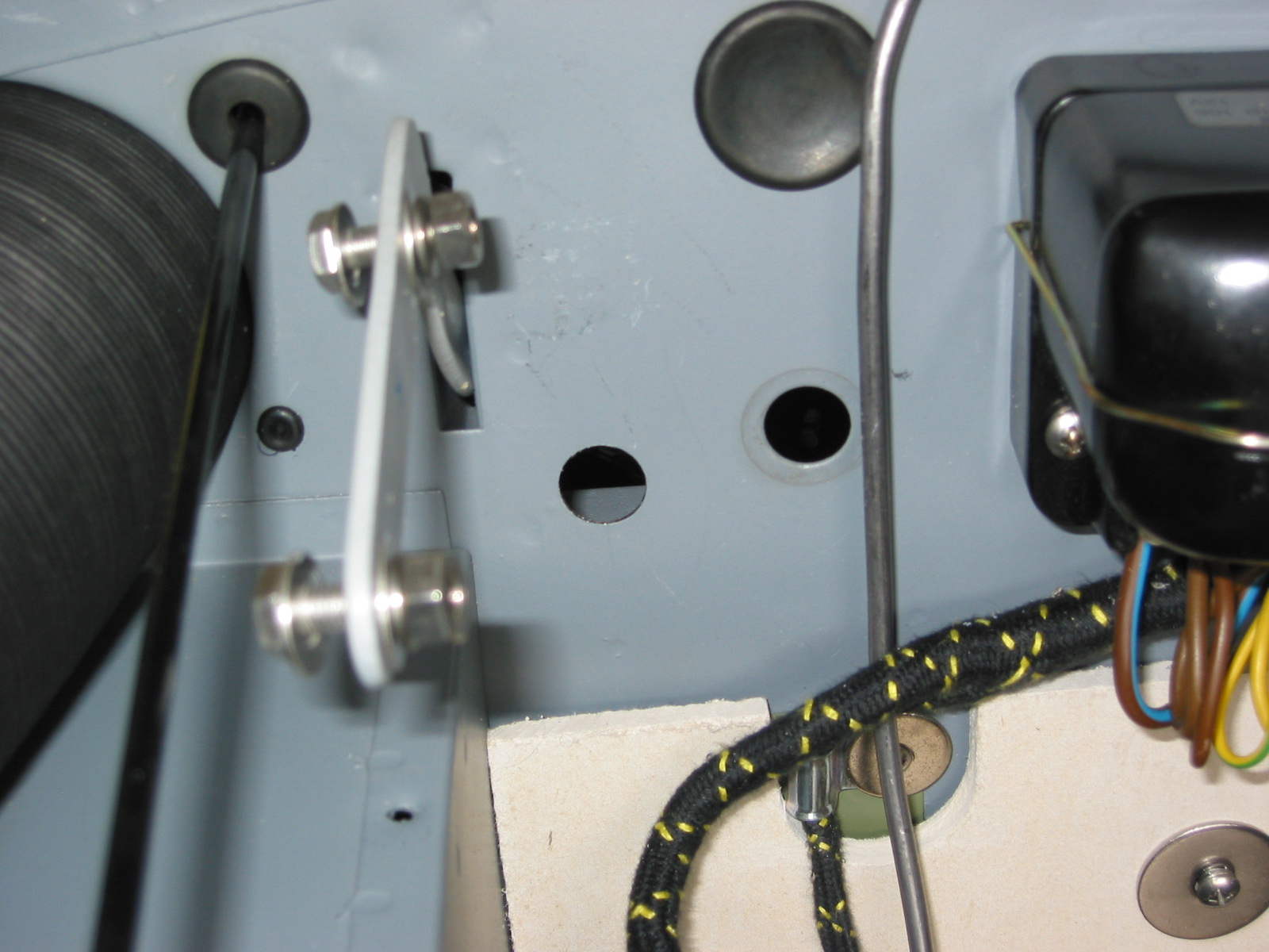
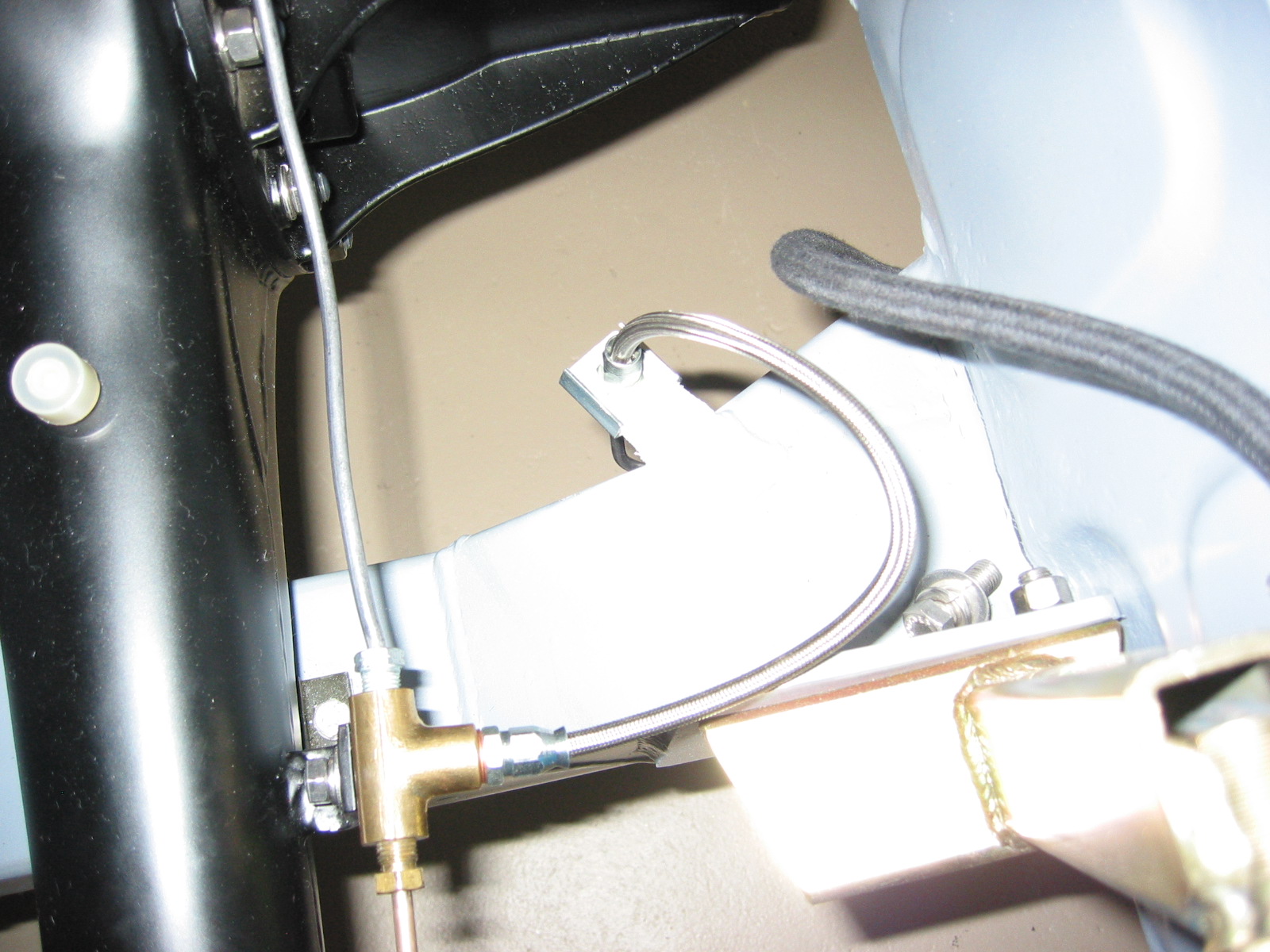
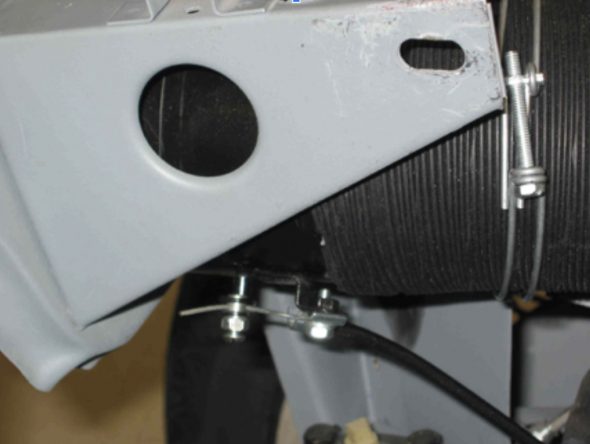
Fresh Air Contol Cable – Passenger Side
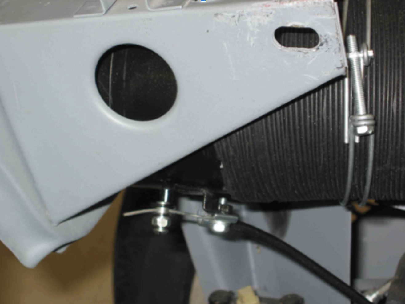
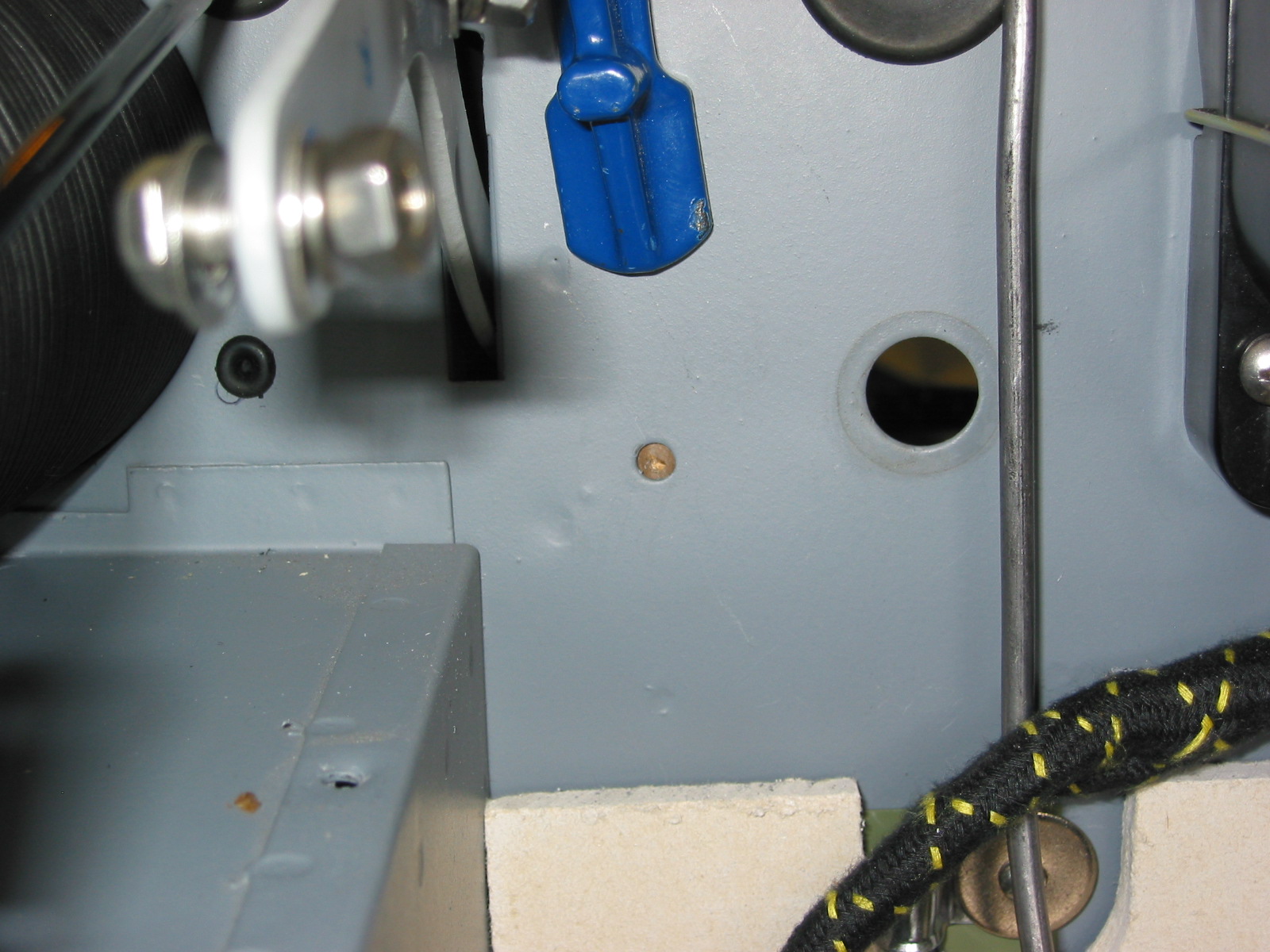
Drilled the small hole in the firewall next to the tach cable grommet to 5/8” and added a rubber grommet to run the new cool air cable through the firewall.
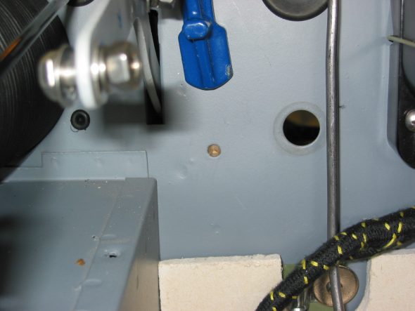
Hole for cold air cable

Hole for cold air cable 2
October 15, 2004
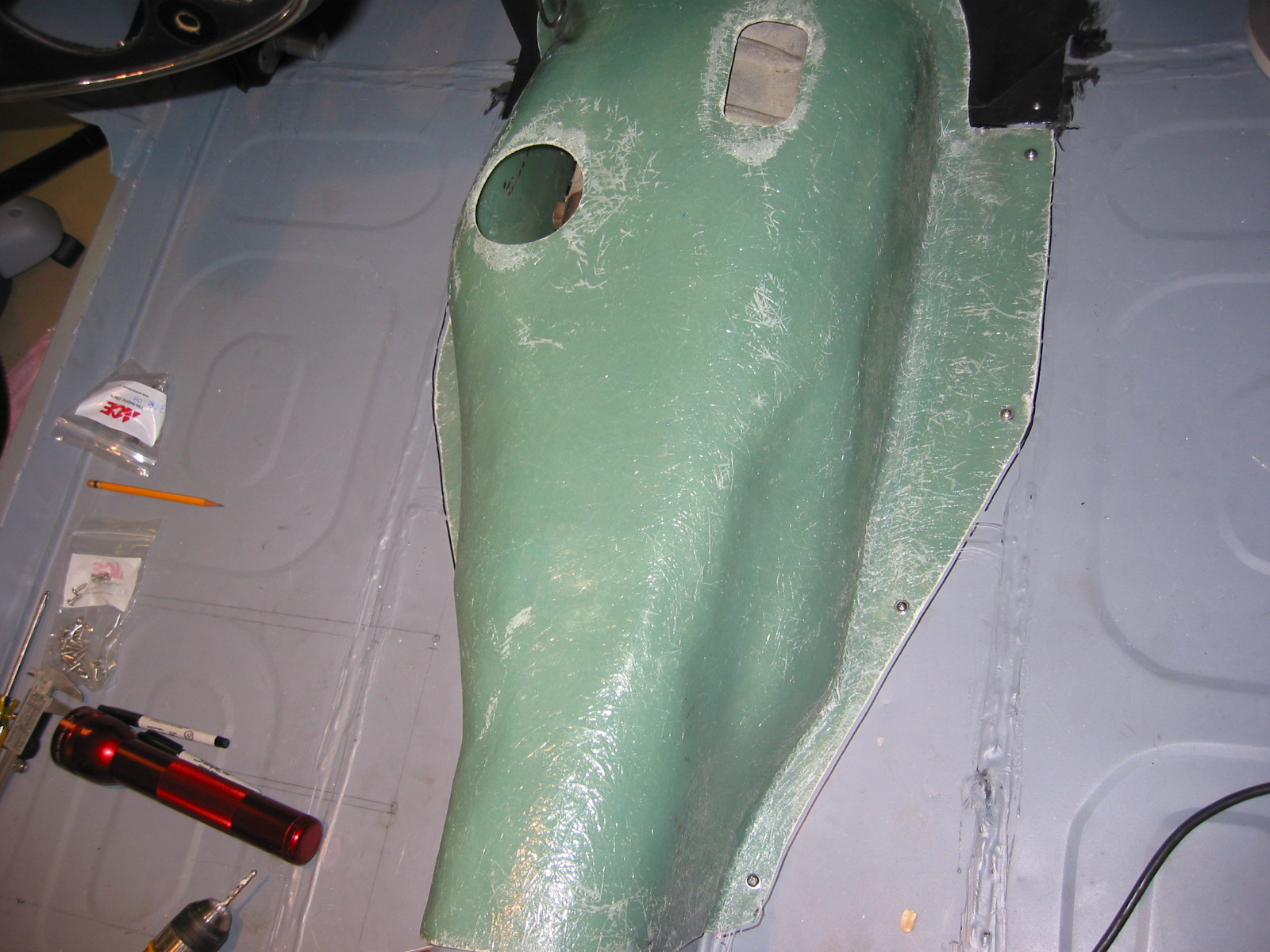
Gearbox Cover and Extension Installation
The original gearbox cover and extension were unusable due to rust. I ordered a new extension panel from Kilmartin and a fiberglass gearbox cover from British Car Specialists. While the cover seemed to be a good fit and will certainly be cooler than the original metal cover, the extension panel did not fit over the Smitty bell housing for the Toyota transmission conversion.

Gearbox cover 1

Gearbox cover extension 1
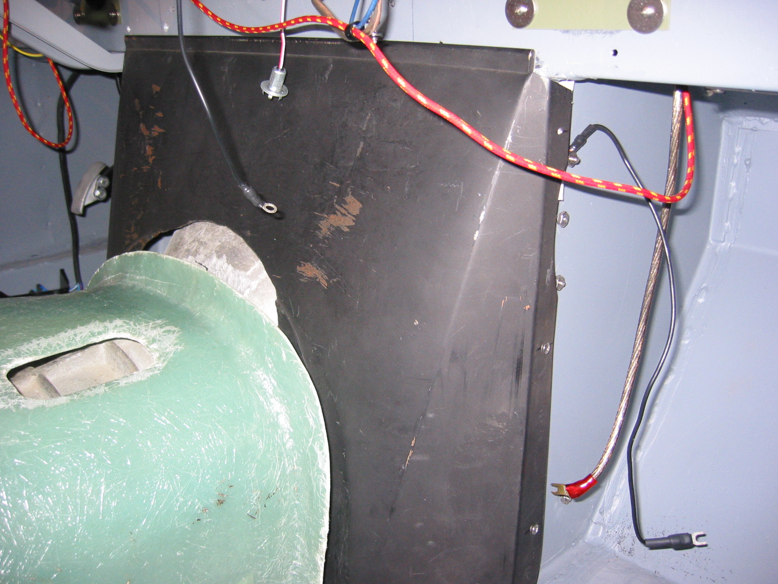
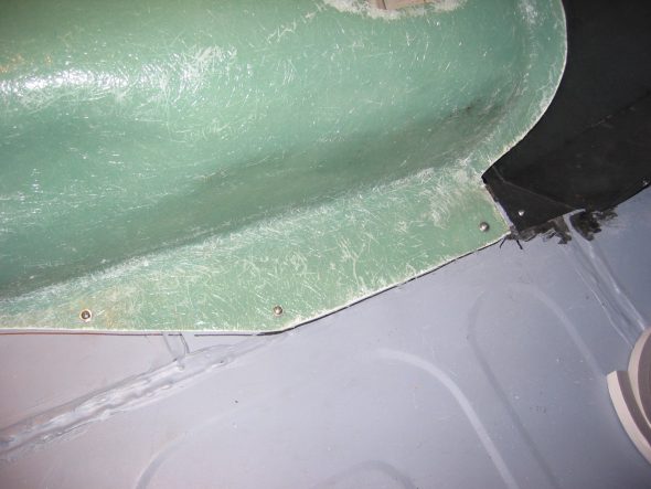
I trimmed the extension panel and then fitted it to the firewall bulkhead. I first placed 1/2” weatherstripping on the bulkhead and then drilled the mounting holes needed – three per side – to secure the panel to the bulkhead. I then drilled two holes in the cover footing to screw it into the frame.
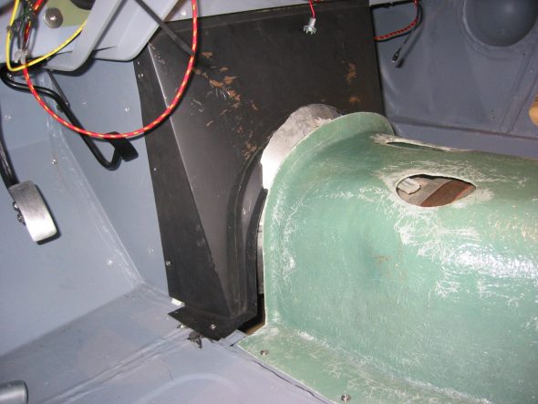
Gearbox cover extension 3
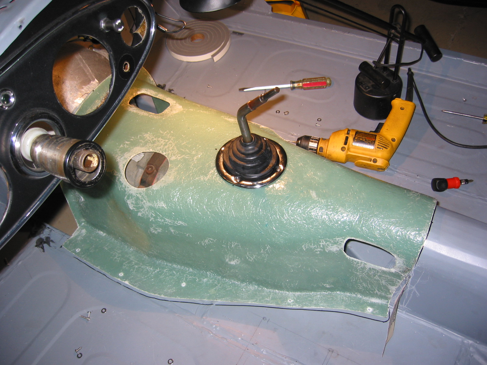
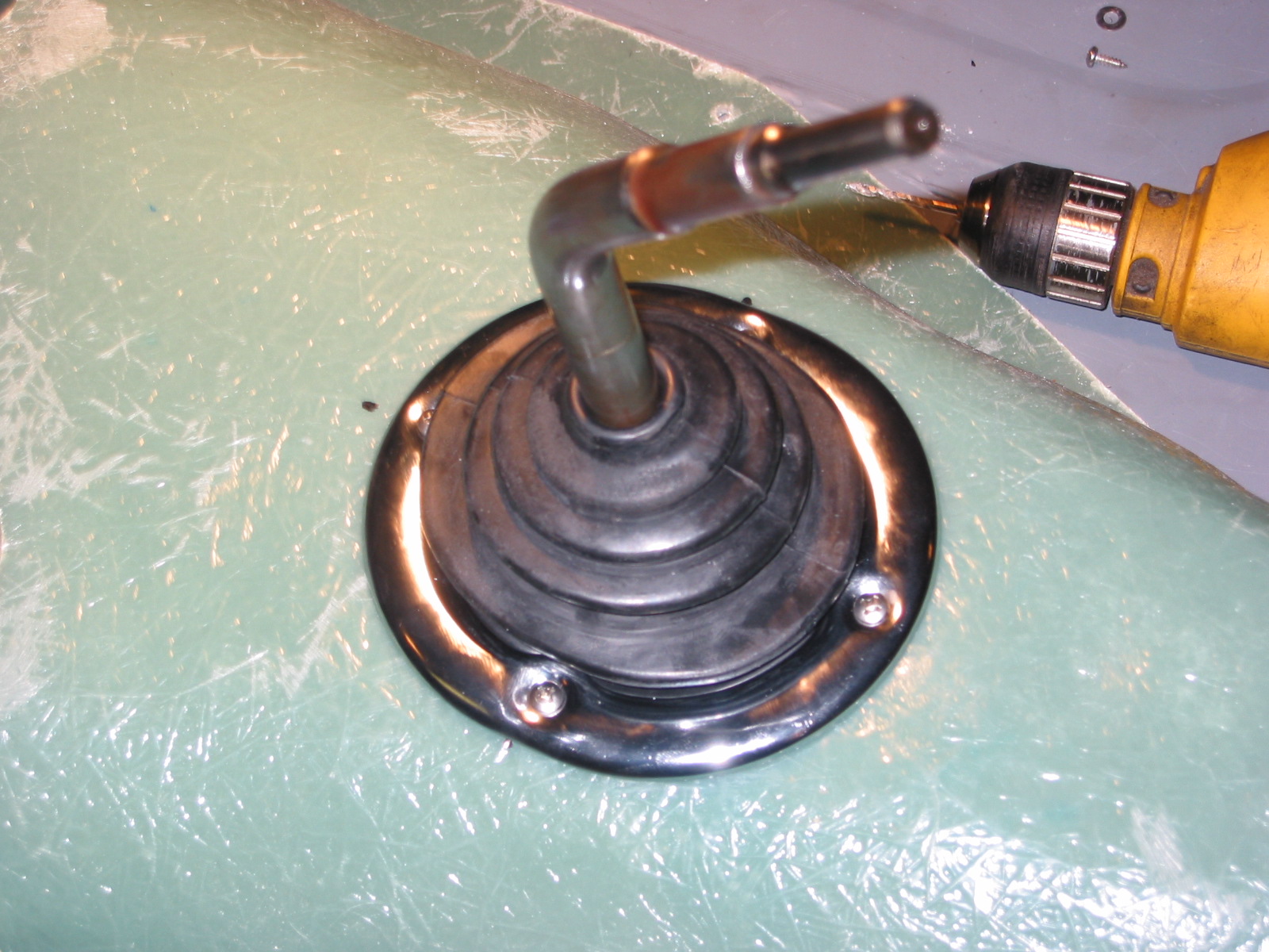
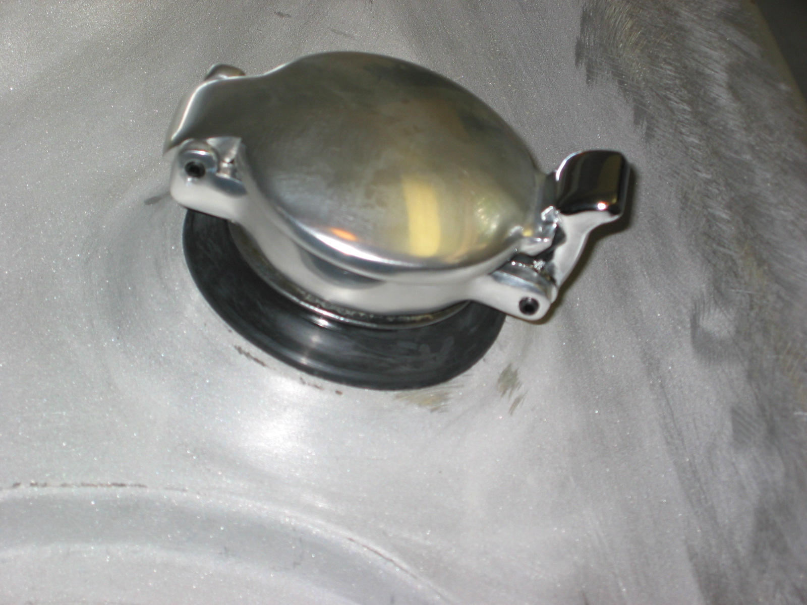
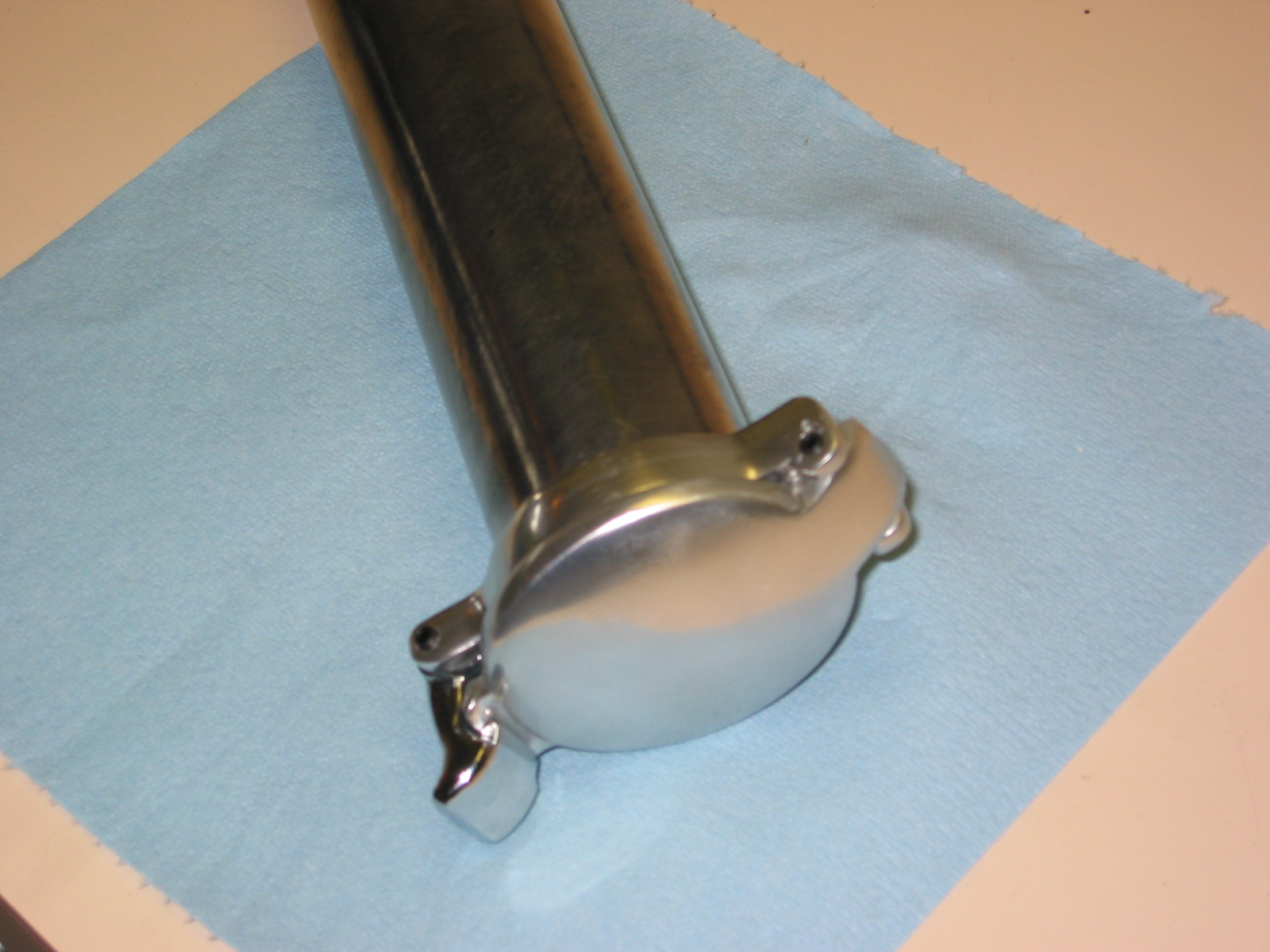
I measured the distance from the metal driveshaft tunnel to the center of the shifter – 13.” Then I installed the cover and measured the same 13” distance and marked it on the cover. I drilled a small hole in the cover just to check the proper location with the shifter. I then drilled a 3 1/4” hole in the center of the gearbox cover for the center shifter. Location was perfect! I used a rubber boot and mounting ring from an MGB as suggested by Smitty. This required drilling 4 small holes for #8 stainless screws.
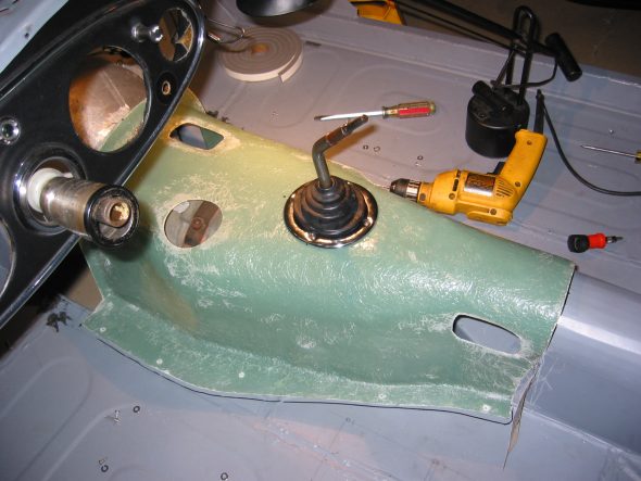
Toyota shifter installed 2
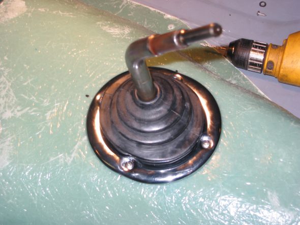
Toyota shifter installed 1
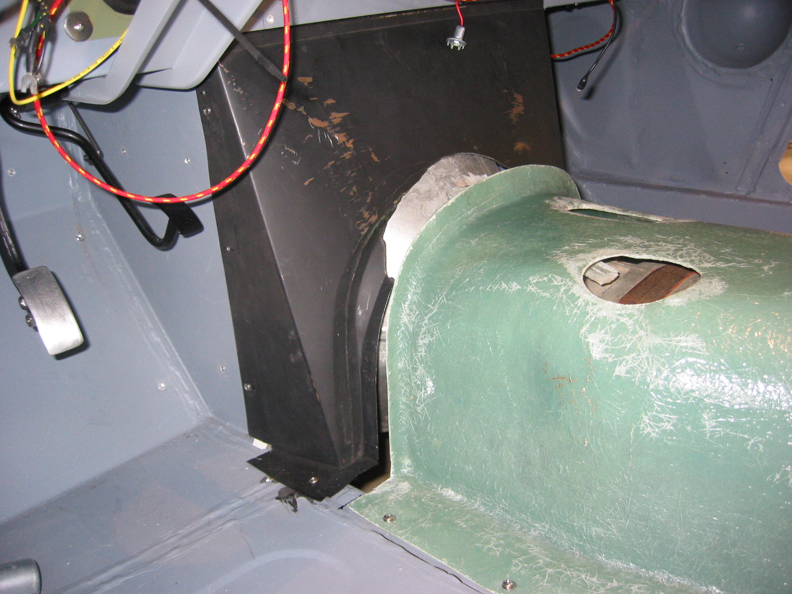
Now that the gearbox cover was properly located I drilled 4 holes into the frame or floorboard on the right side of the cover and 5 on the left side and fastened the cover to the floor.
Gearbox cover 3
I was then able to establish what would become the permanent relationship between the gearbox cover and the extension panel. I measured and drew a template for the floor and measured the distance from the top of the cover to the top of the extension panel – 7 3/8.”
Finally, I recreated the assembly on a piece of 1/2” plywood and secured the panels to the plywood. I added an extra mounting screw on the floor tab of the extension panel to help steady the panel.
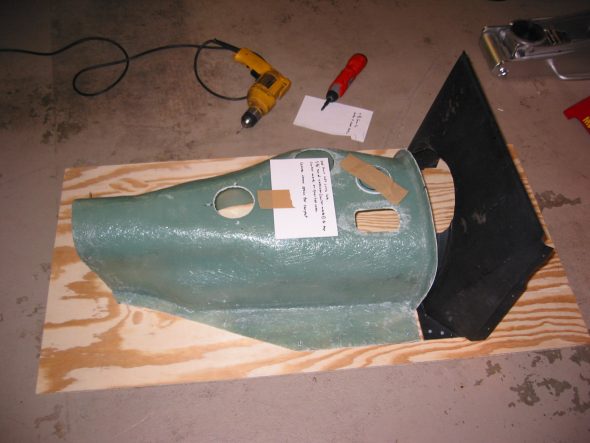
Gearbox cover assembly 1
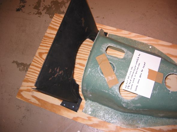
Gearbox assembly Cover 2