April 18, 2004
Front Suspension Installation Continued
I had the front swivel or king pins refurbished by Bruce Phillips at Healey Surgeons. I then followed the steps in the workshop manual:
Fit the new lower fulcrum pin into the lower trunnion being careful to center it, and then secure it with the two cotter pins.
Placed the cork rings in their recesses on the lower trunnion and then fit the lower wishbone arms to the trunnion. Ensured that the half-moon cotters were correctly positioned and then greased and screwed the new steel bushes partially home.
Bolted the lower spring plate to the wishbone arms to establish proper positioning.
Threaded the steel bushes home evenly and then backed off a flat or two until .002” feeler gauge will fit between wishbone arm and the bush. Tighten cotters but was careful not to overtighten. The lower trunnion assembly should operate freely in the screwed bushes.
Place the cork washer on the top of the swivel pin and pushed it down to the bottom. Smeared swivel pin shaft with engine oil and placed the hub assembly on the swivel pin.
Fit a staybright washer followed by an oilite washer and then another staybright washer on top of the hub assembly on the pin. I soaked the oilite washer in oil overnight so that it would absorb the oil into its pores.
Fit the upper trunnion and swivel nut. Nut should be tightened down (40 to 60lbs of torque) to allow a maximum of .002” lift. Pin should turn freely but snuggly.
Then released swivel pin nut.
Removed the spring plate from the wishbone arms to gain some flexibility in fitting the arms to the frame brackets.
Fit the two poly bushes to each lower wishbone link and pushed them into the frame brackets.
Replaced the spring plate.
Inserted the fulcrum pins through the bushes and installed the second set of bushes through the frame bracket. Put the special washer with tab locator on the back of the bracket and lightly secured with a castel nut, not screwed home.
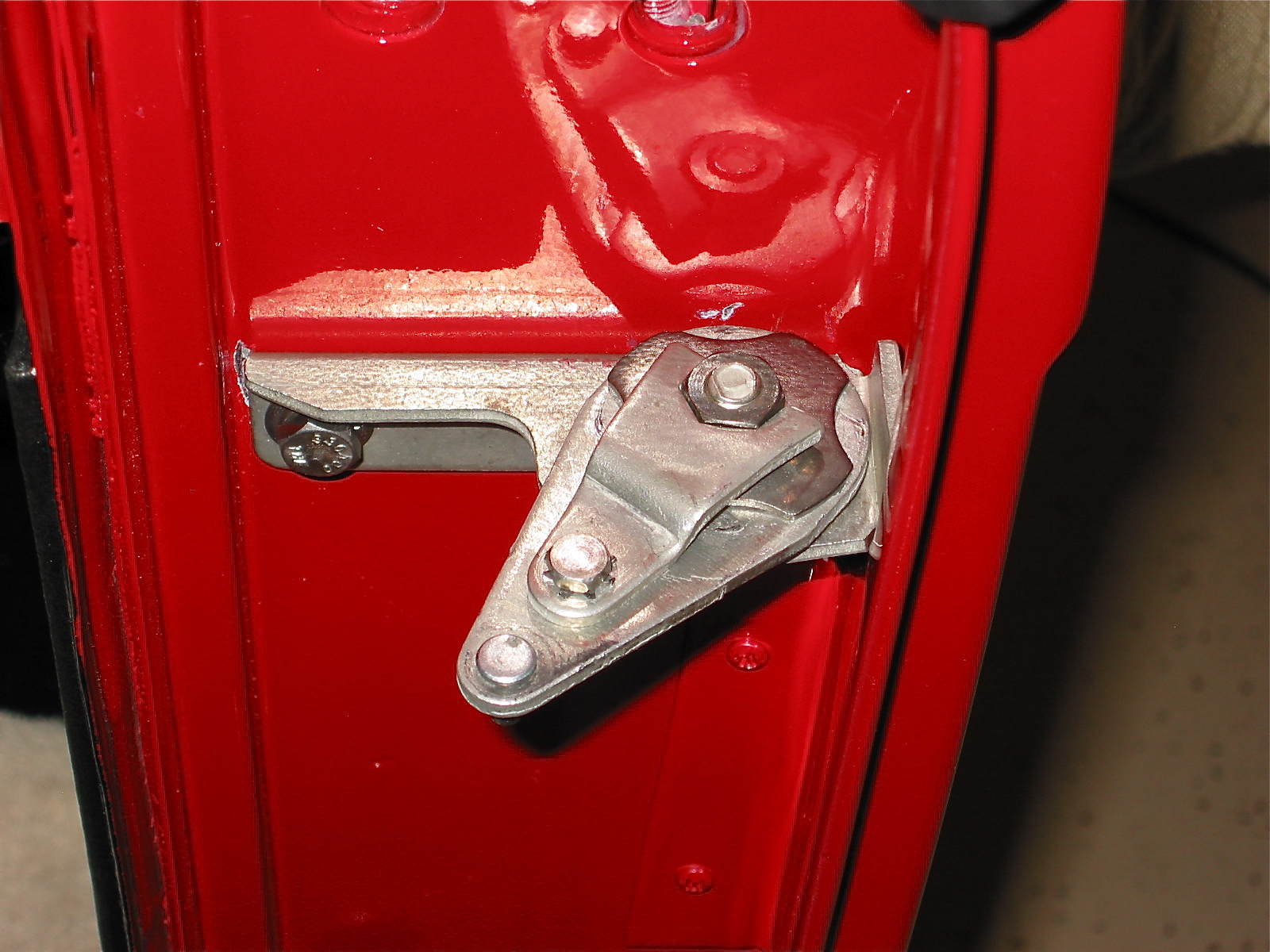
Fit the lever shock to the shock tower and insert mounting bolts. Fit the Putzke’s tube shock conversion bracket on the front of the lever shock with special long bolts and tightened lightly.
Front suspension left 6
Front suspension left 7
Placed the new upper trunnion bushes in place. I used poly bushes supplied from Udo Putzke.
Loosened the shock absorber arm mounting bolt.
Placed the upper trunnion with the bushes in position between the shock arms. Refit the fulcrum pin and tightened lightly after securing to the shock absorber.
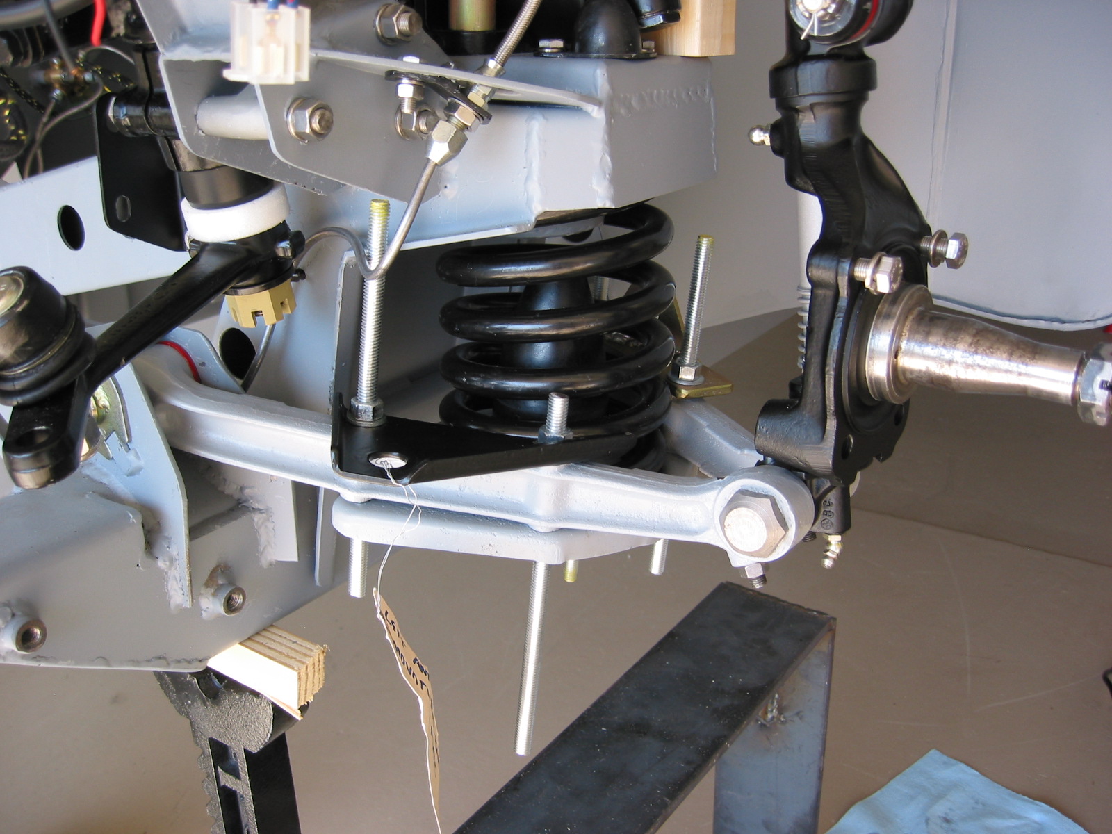
Then set the assembly under proper load position. Accomplished by placing a two inch block (distance piece) under the shock arm opposite the rubber buffer.
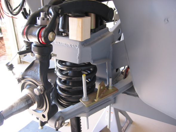
Front suspension left 4
Tightened the fulcrum pin castle nuts for the lower wishbone arms in the frame brackets and insert split pins.
Tightened the four shock bolts to the shock tower plate.
Tightened the upper trunnion fulcrum pin nut and place split pin.
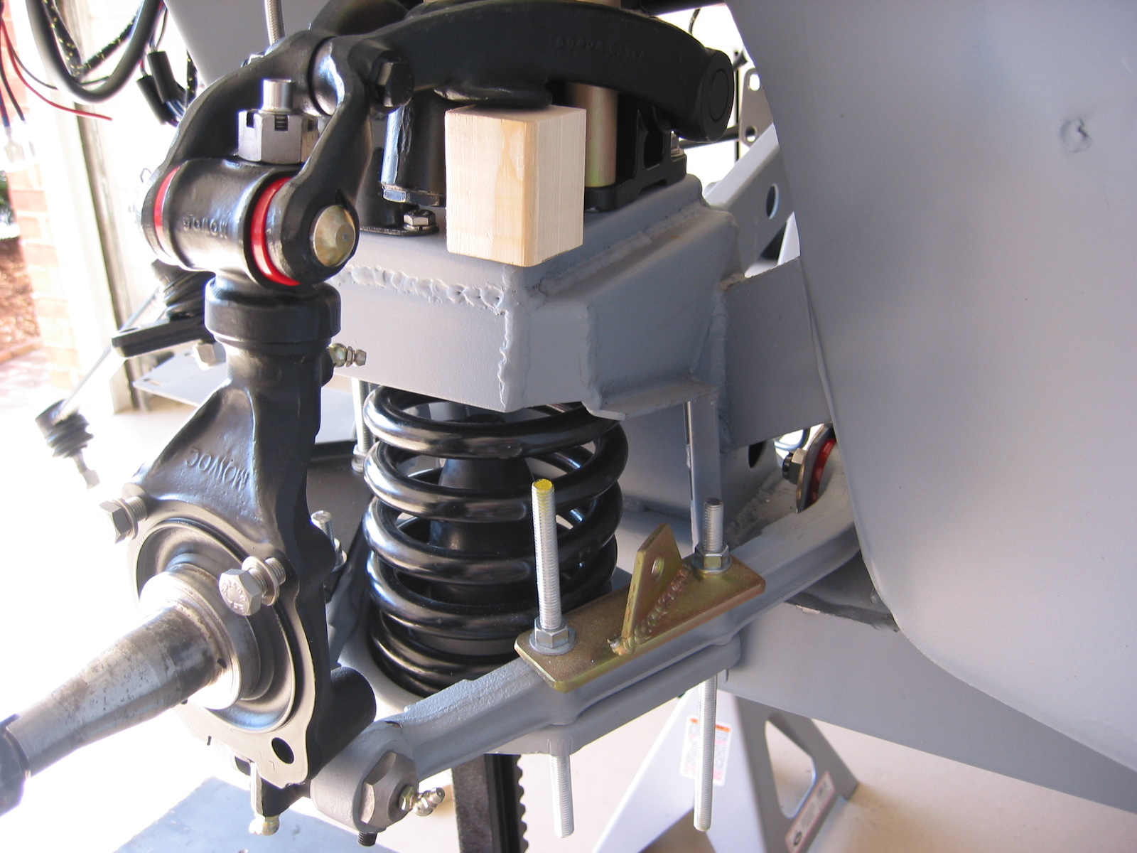
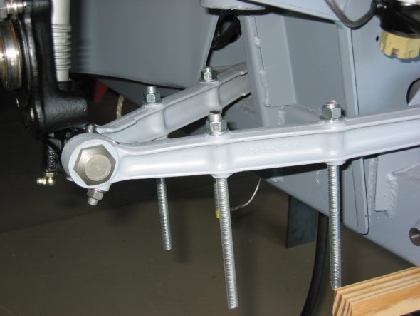
Removed the spring plate and then used 3/8” threaded rod in seven inch lengths to hold new coil spring and plate in place. The lower mounting bracket for the Putzke tube shock conversion was attached to the rear lower wishbone arm at this time.

Front suspension left 2
Gradually tightened the rods until fully in place. Then replaced rods with proper spring plate bolts and tightened.
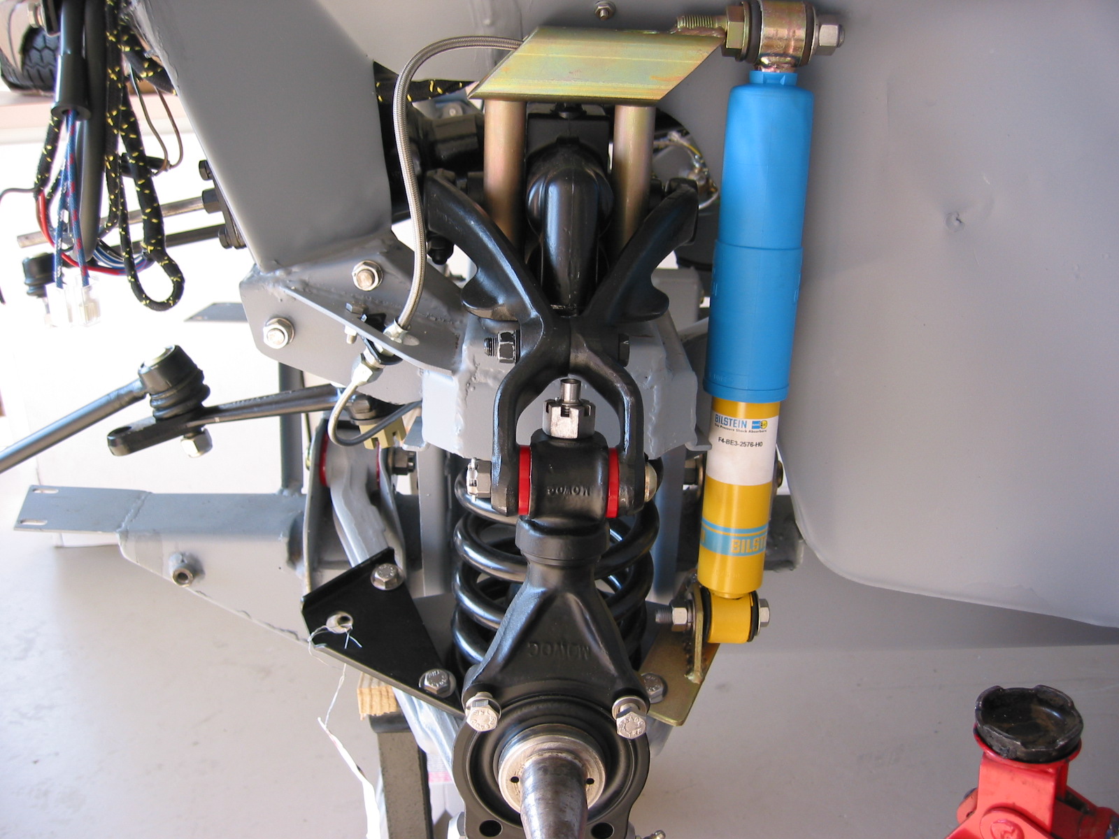
Installed new tube shock which required jacking up the shock tube slightly to align the mounting holes.
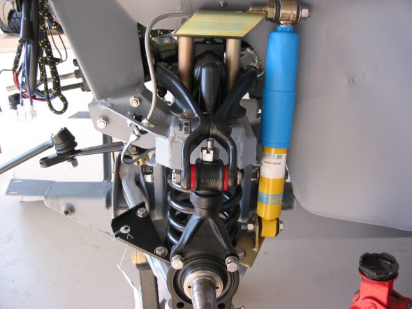
Front suspension left 5
April 24, 2004
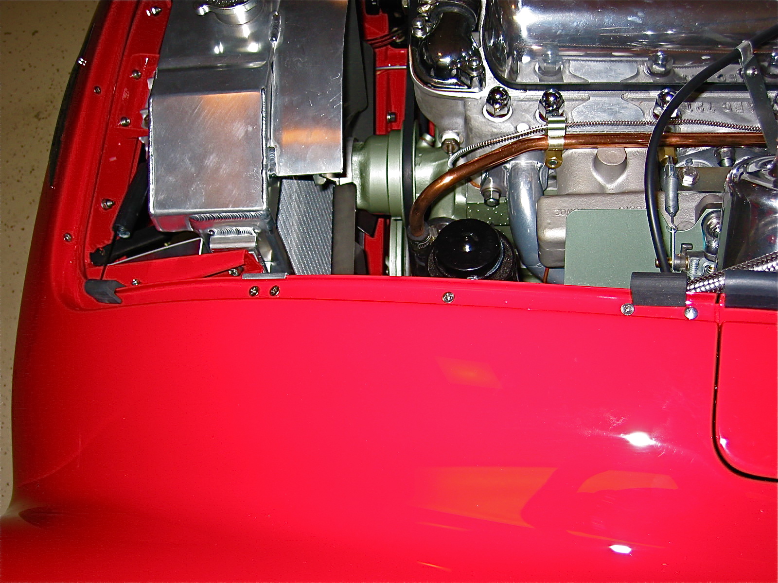
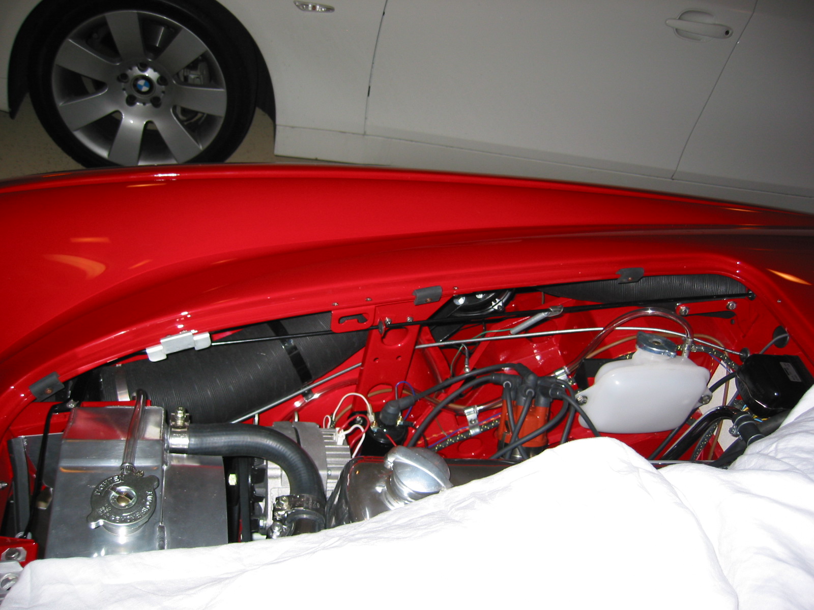
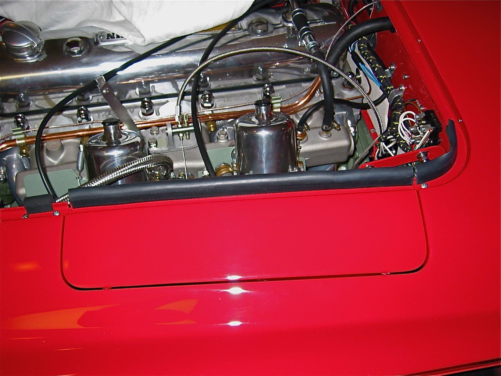
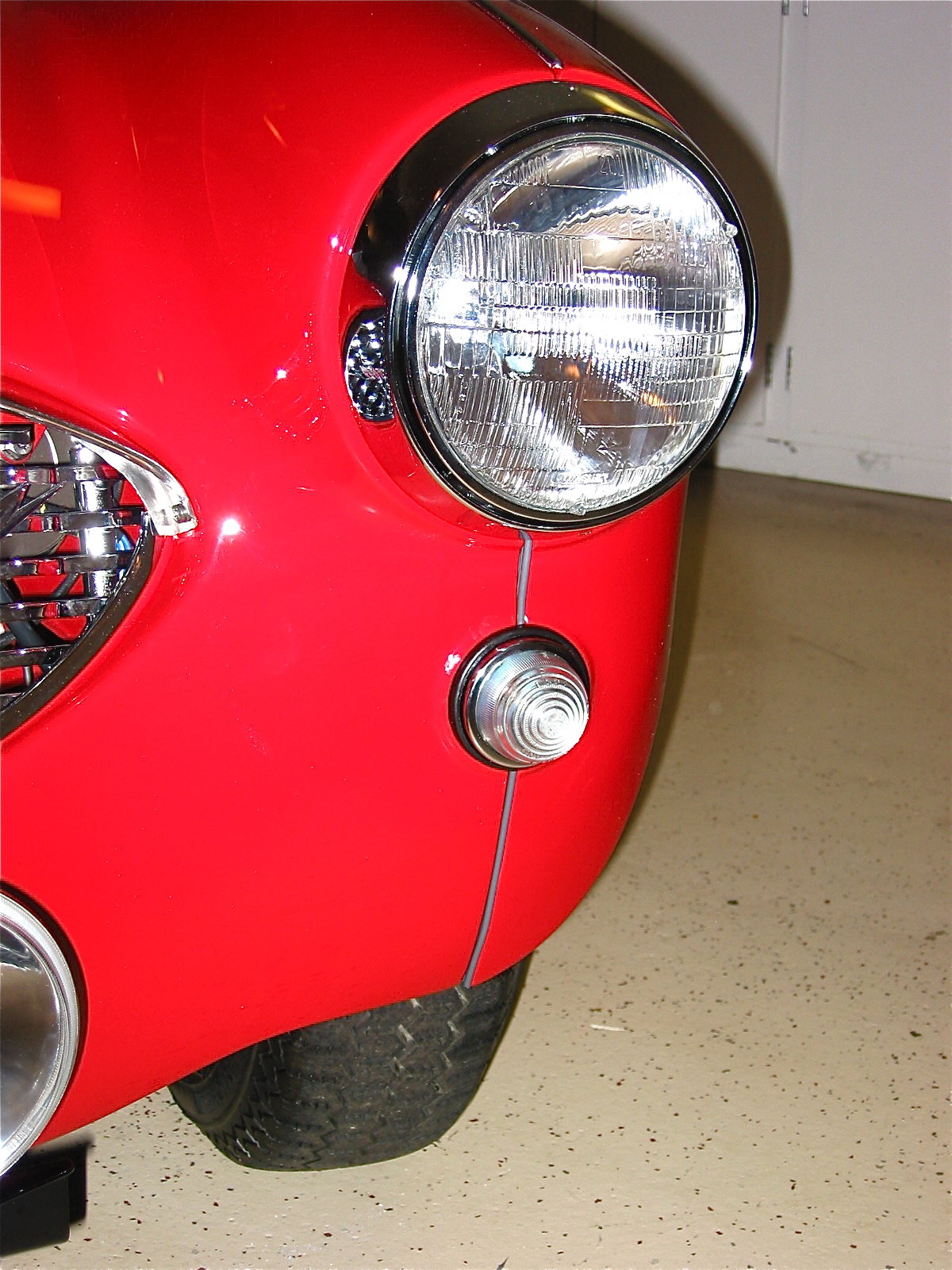
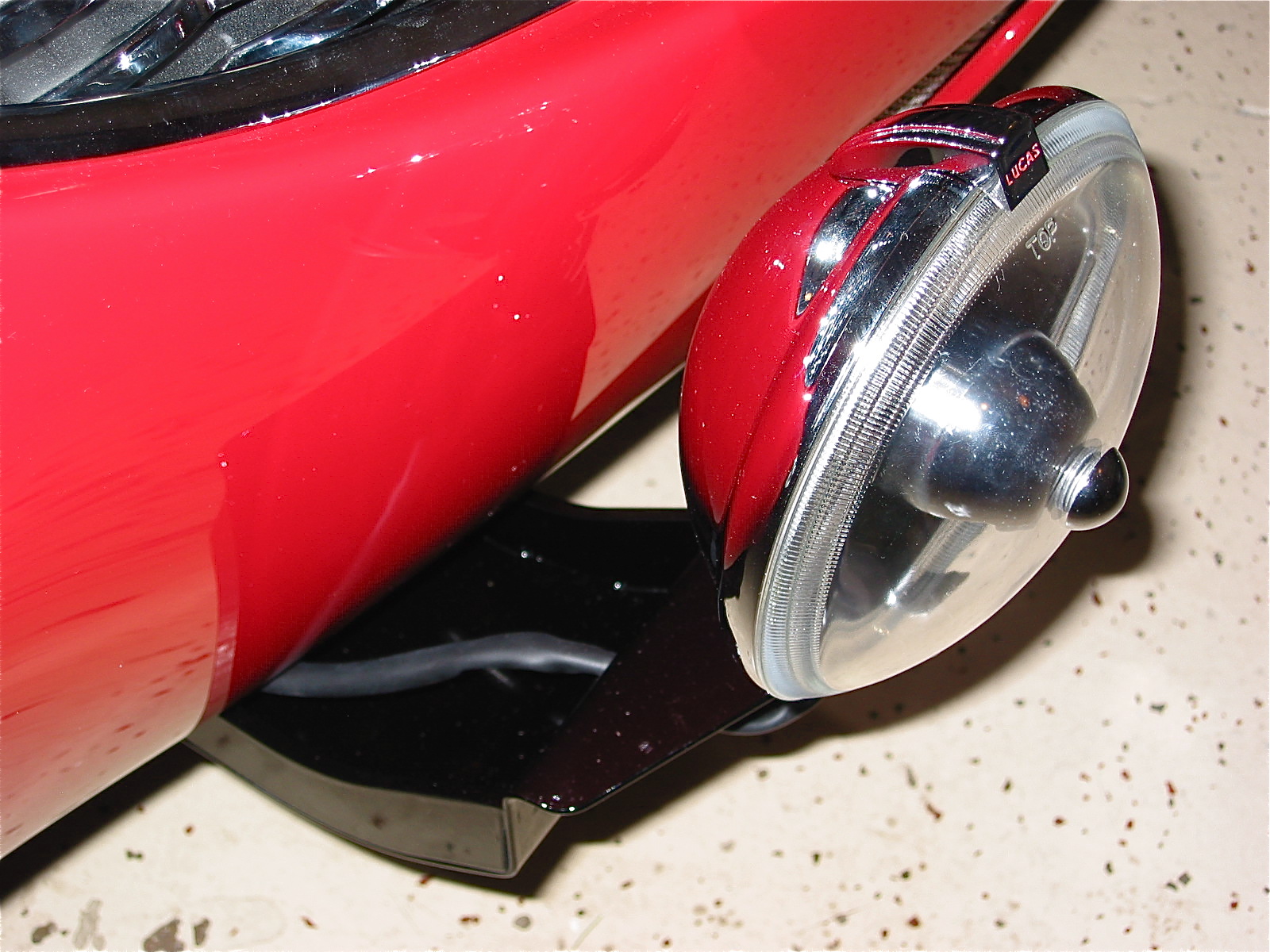
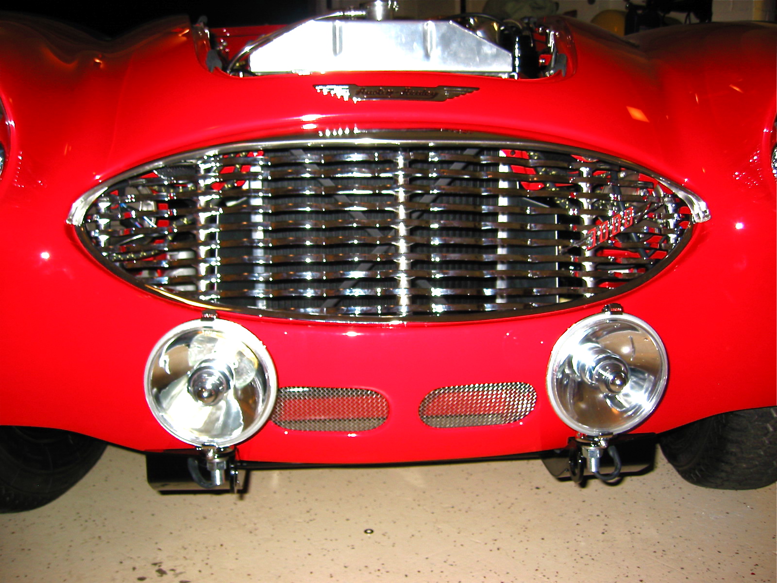
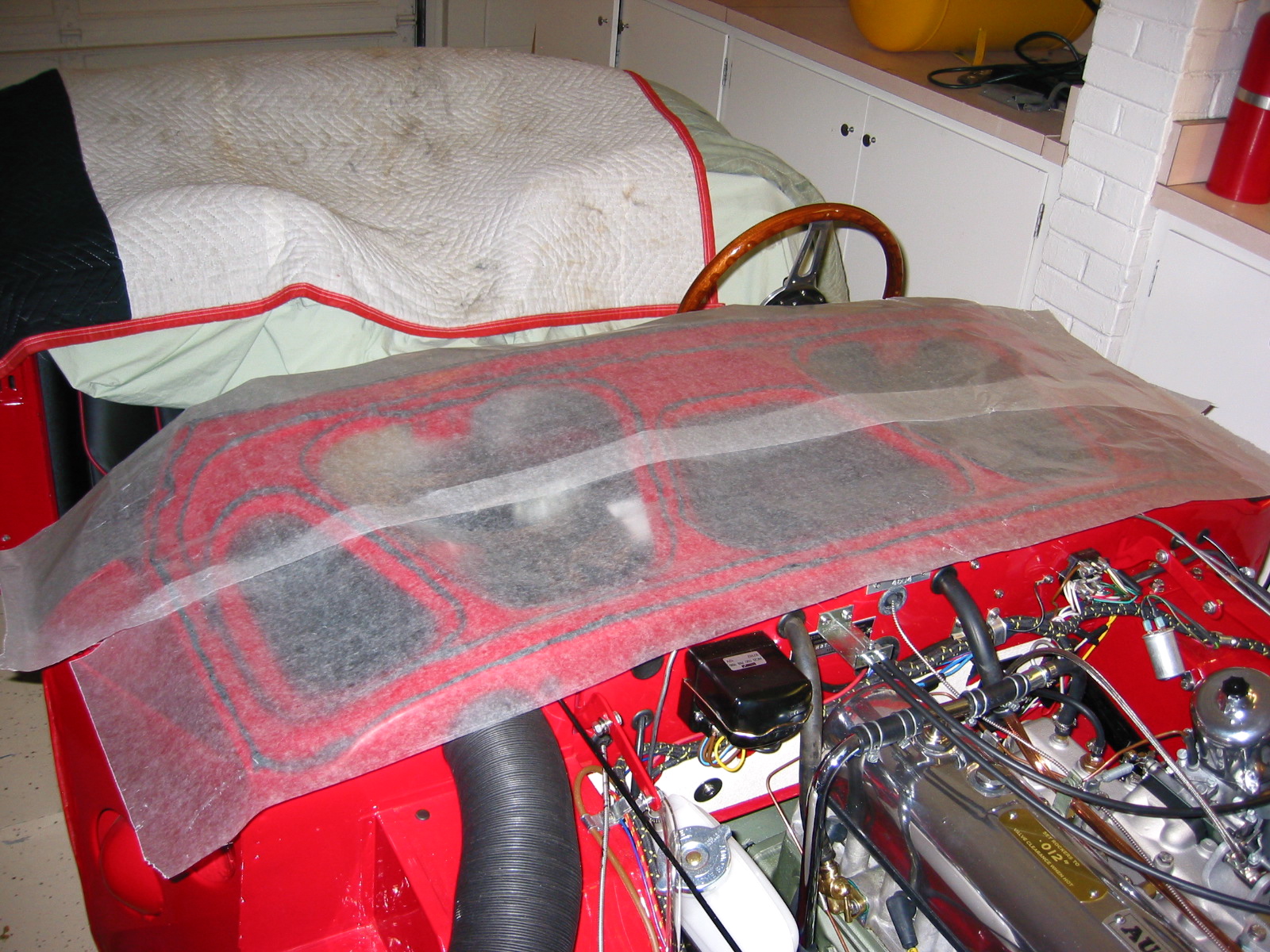
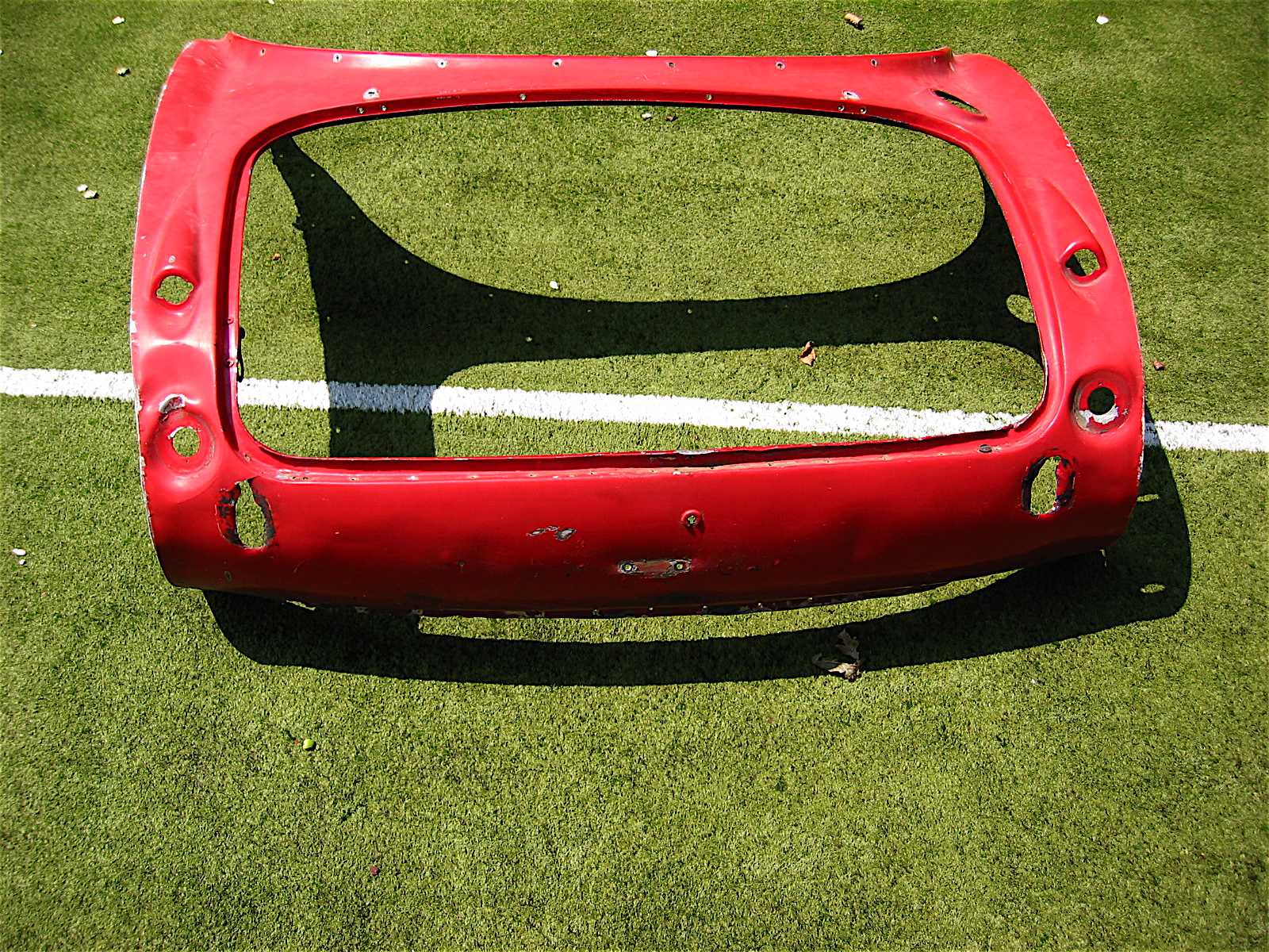
Front Shroud Grill
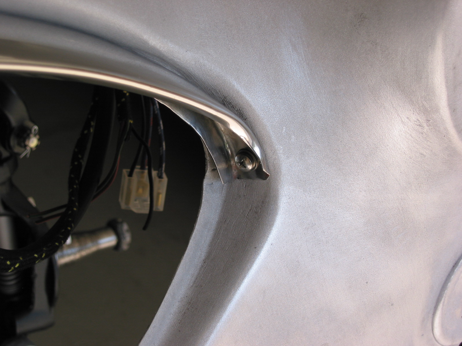
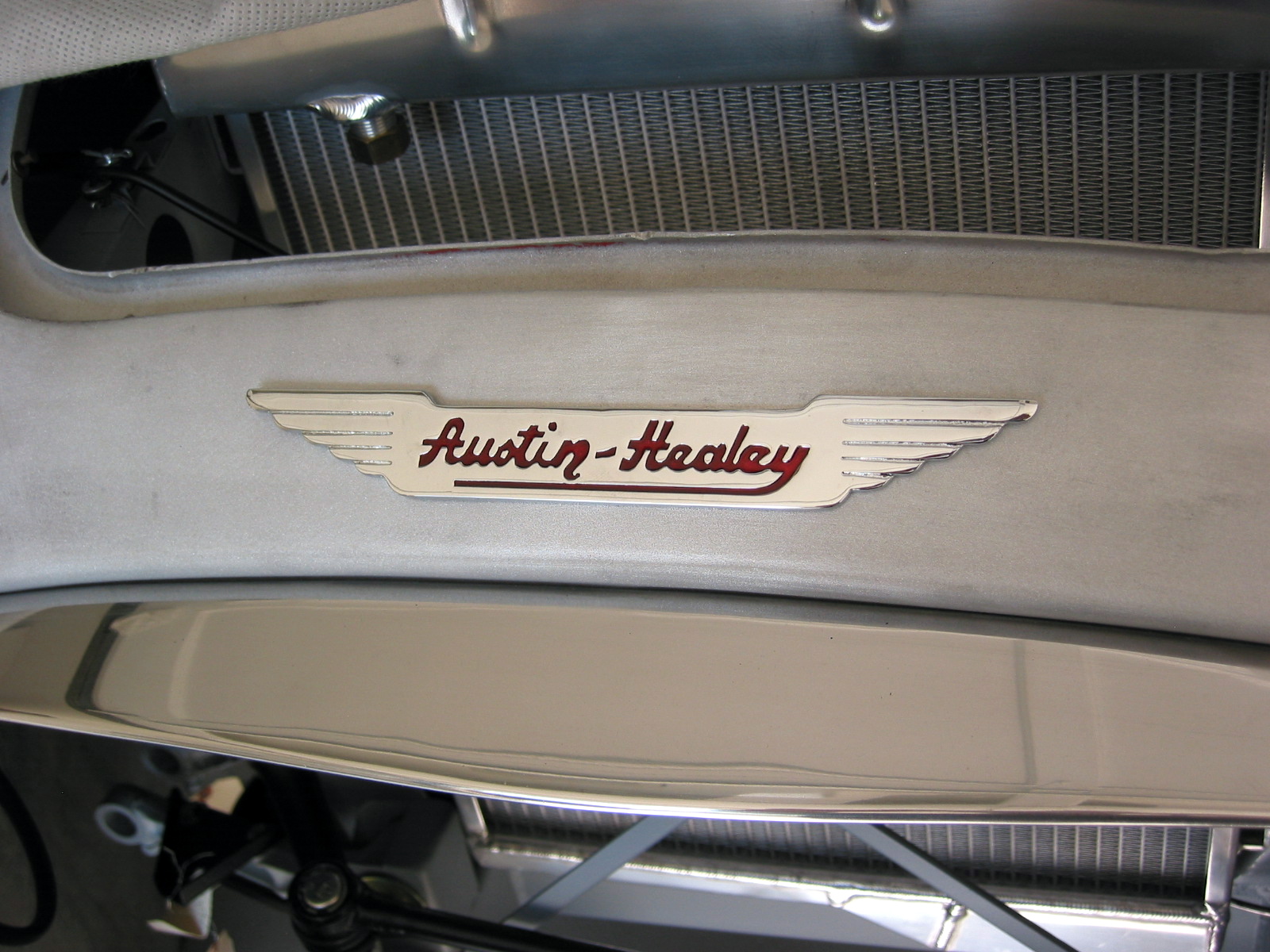
I couldn’t resist finding out how the grill would look in the shroud so I polished the original upper surround piece and installed it along with the Austin Healey motif on the shroud. The motif came from Hemphills and looked good. The upper surround uses 1/4” – 28 x 5/8” with two #10 – 32 x 1/2” screws on the left and right sides. The motif pieces has #8 posts.
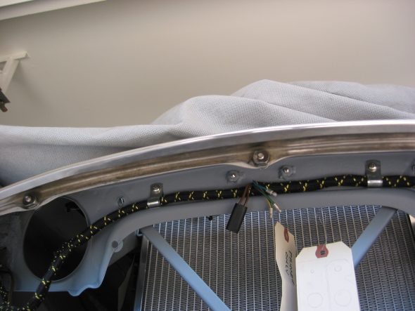
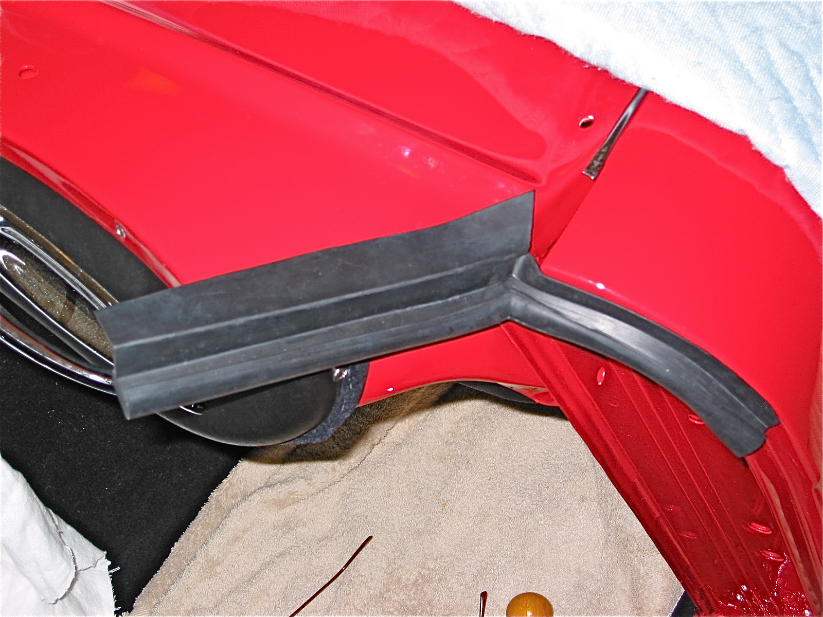
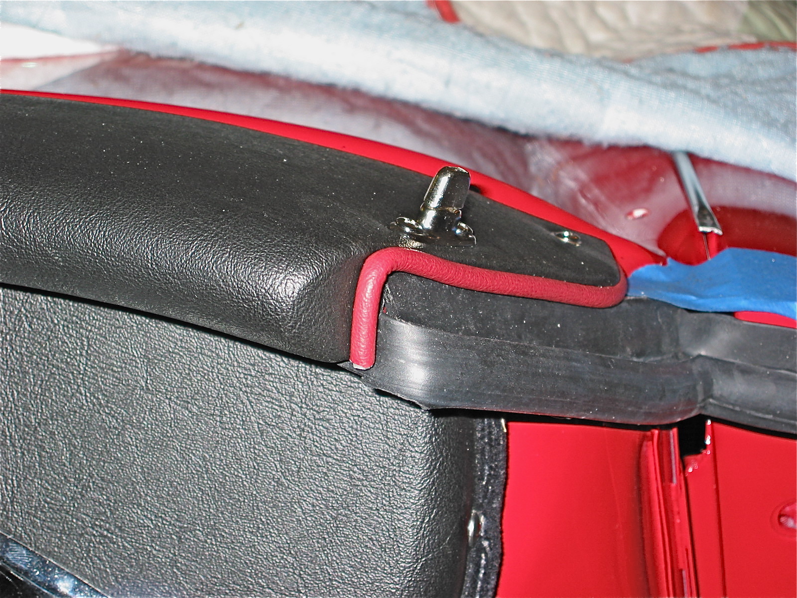
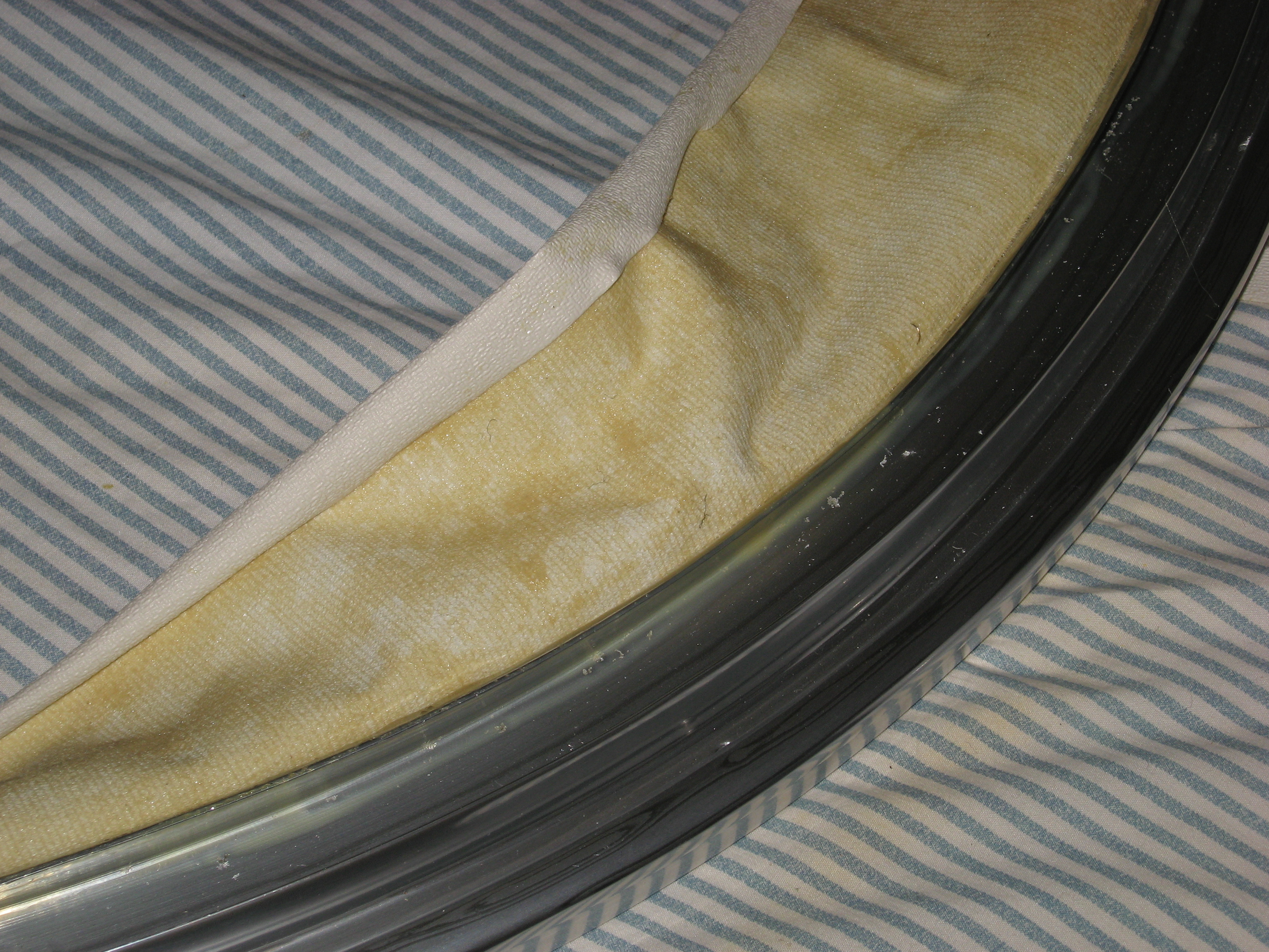
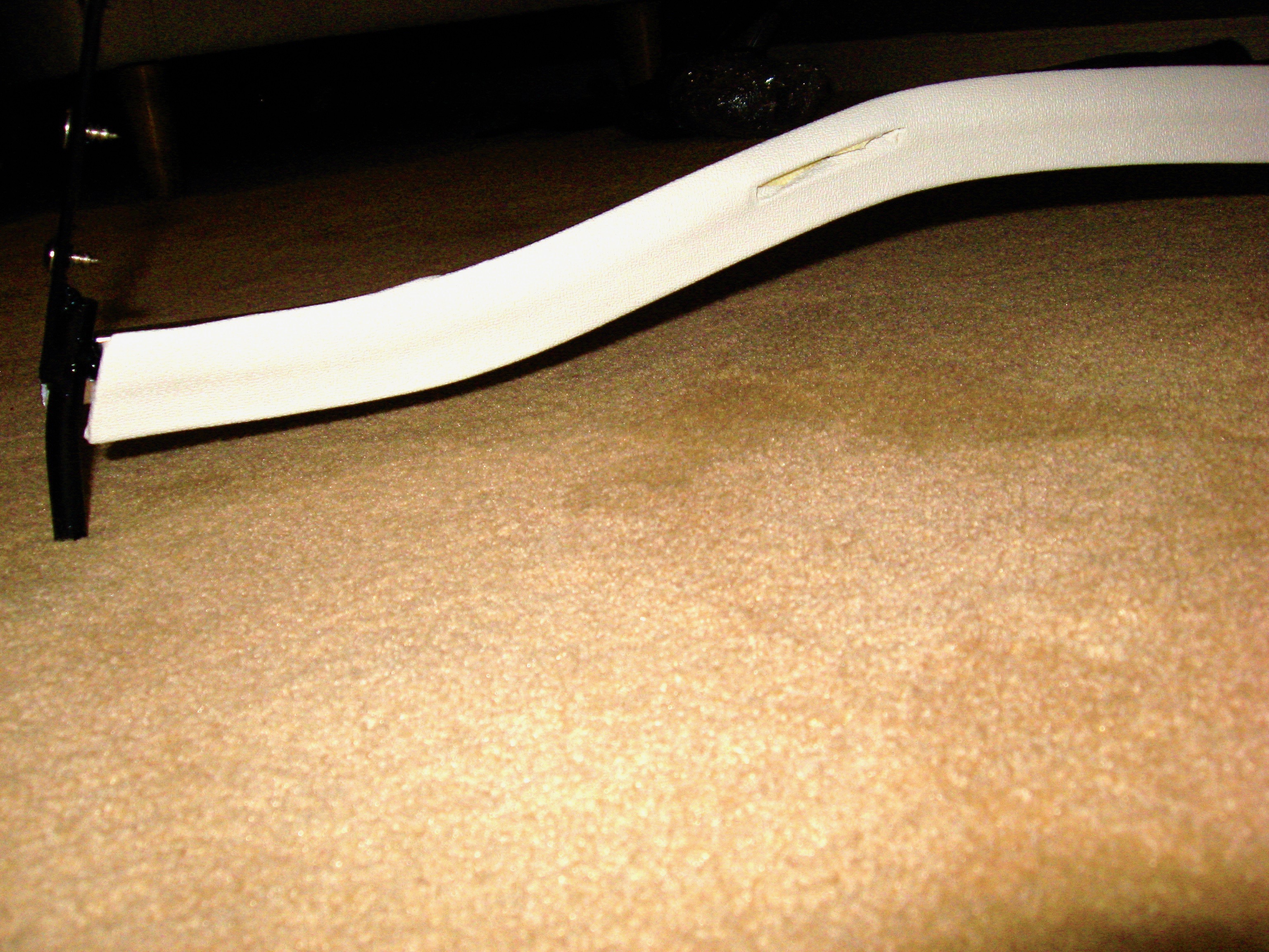
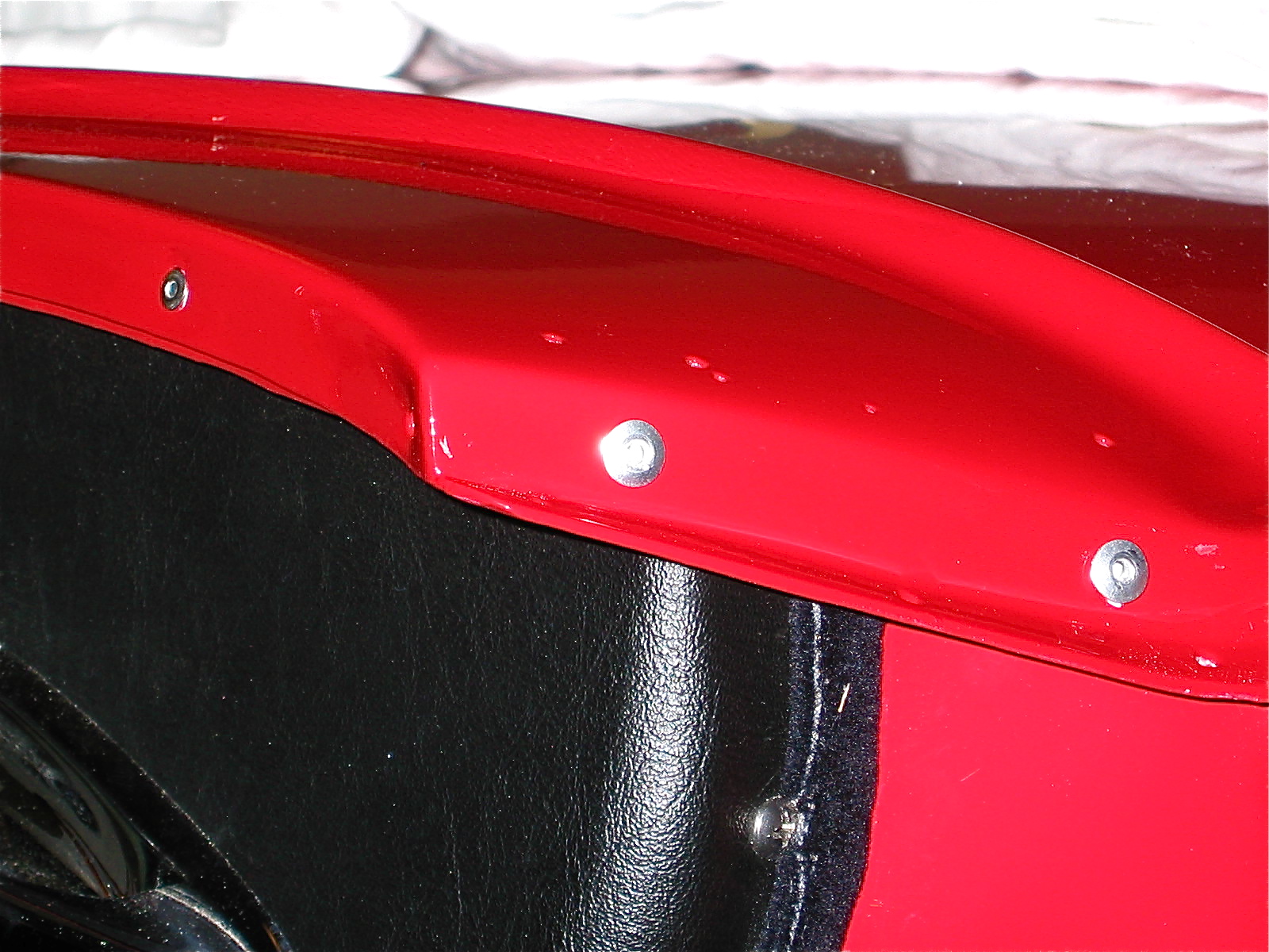
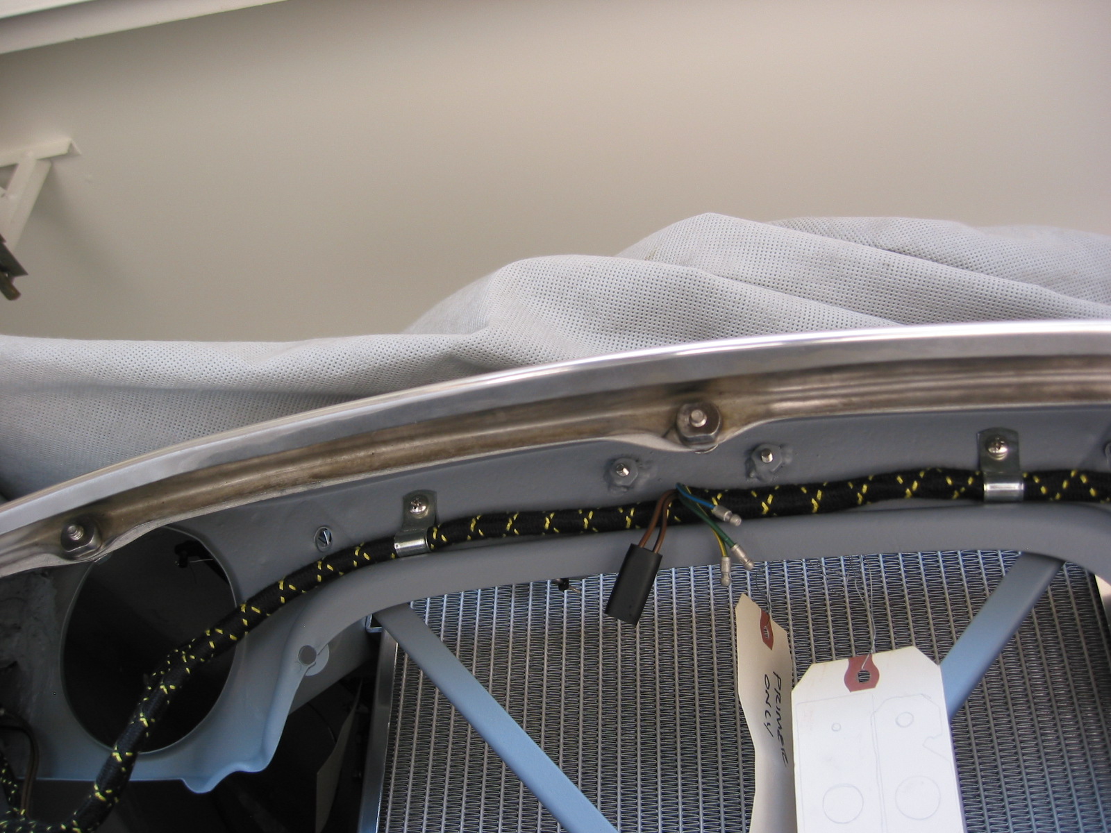
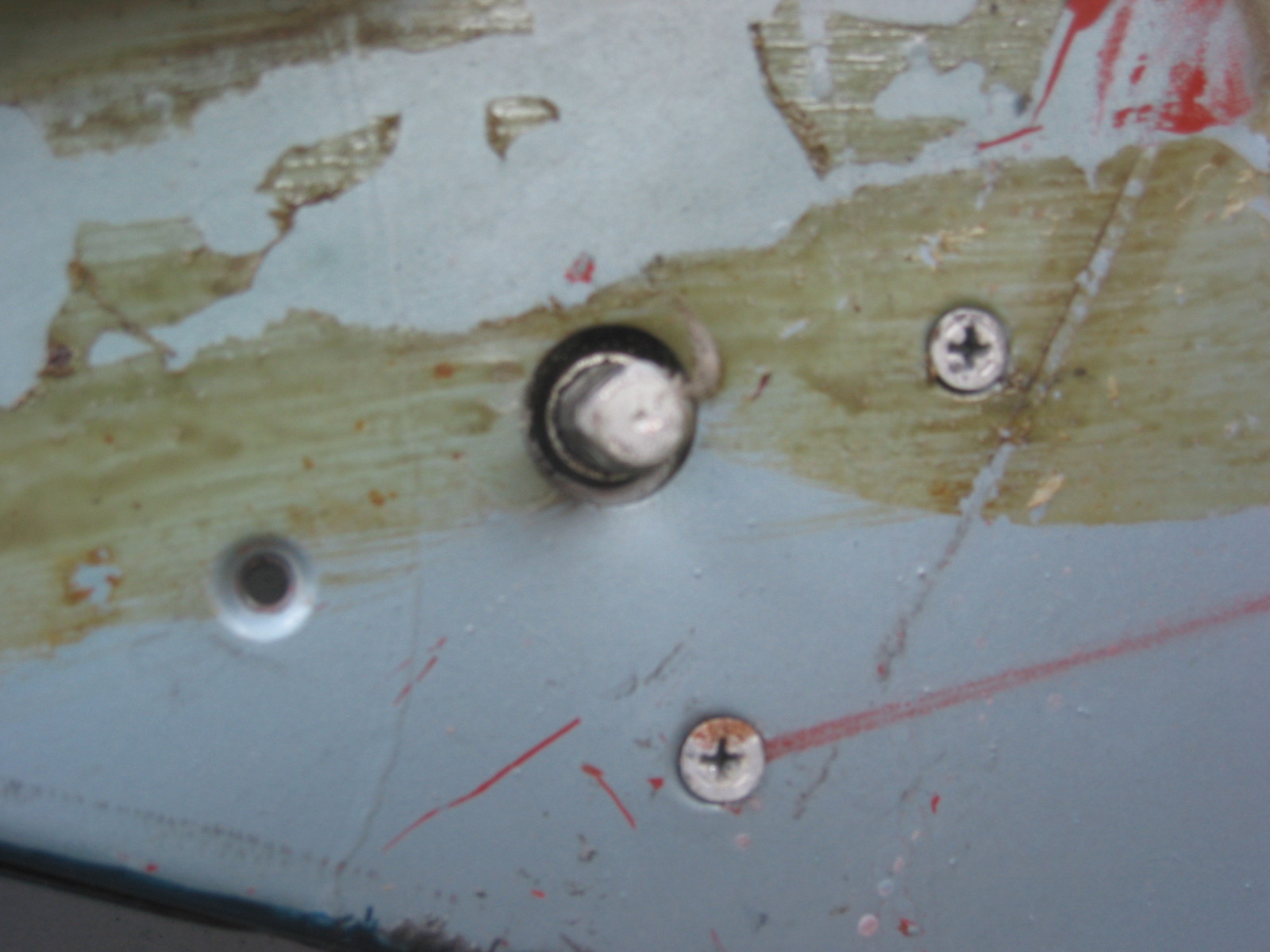
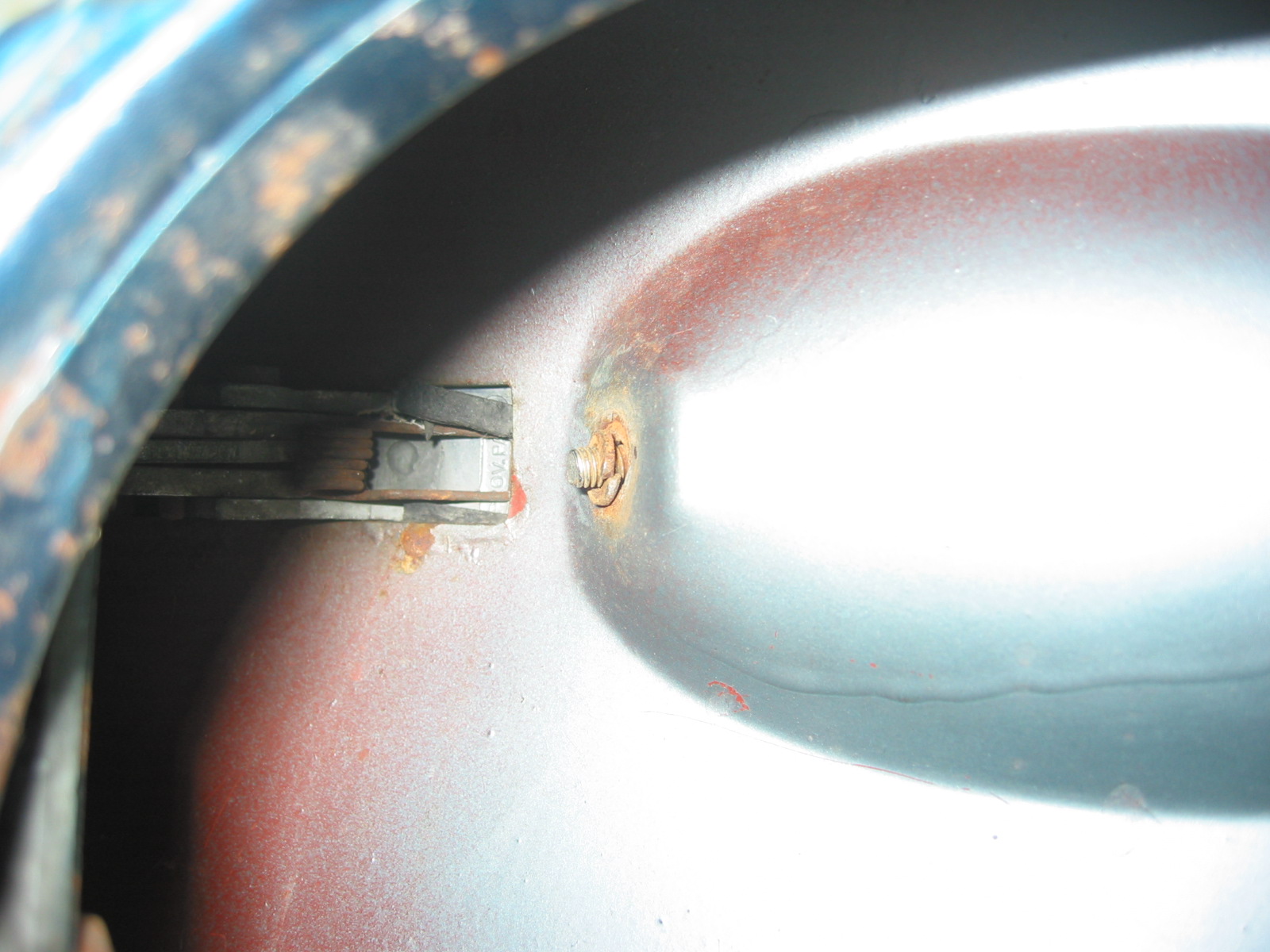
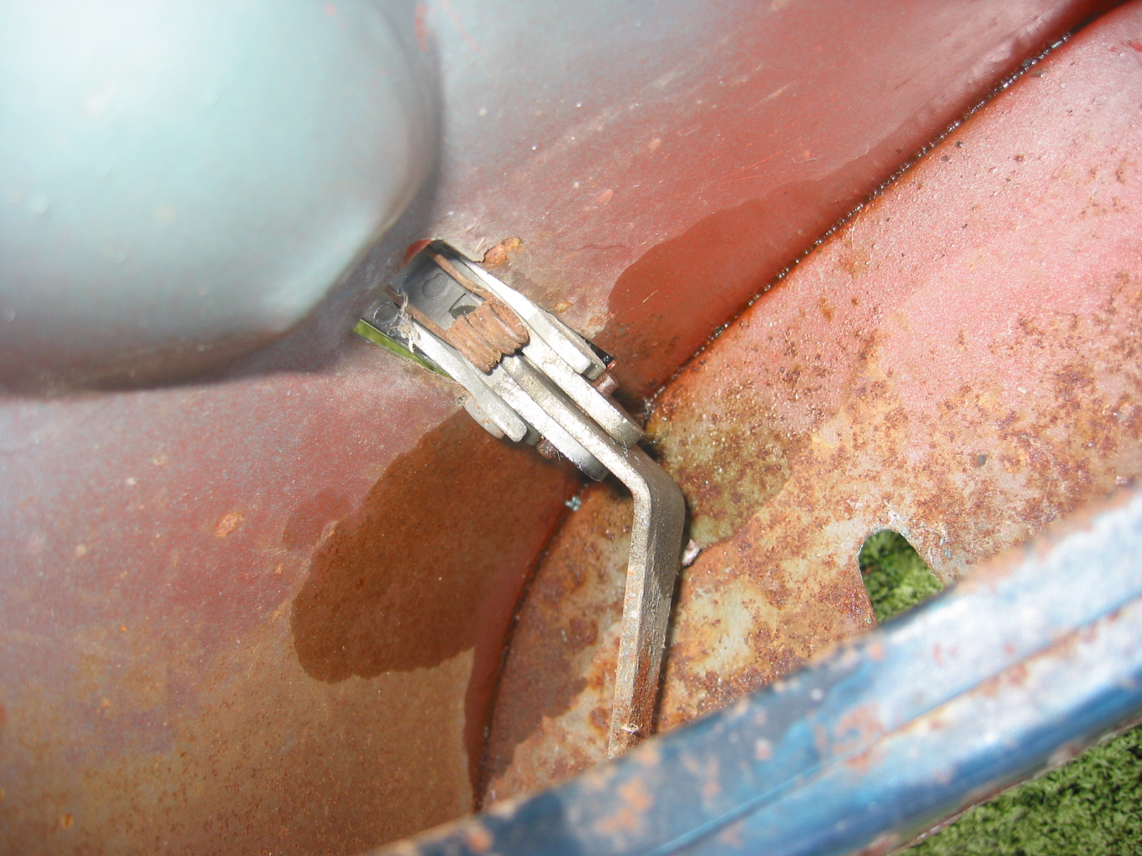
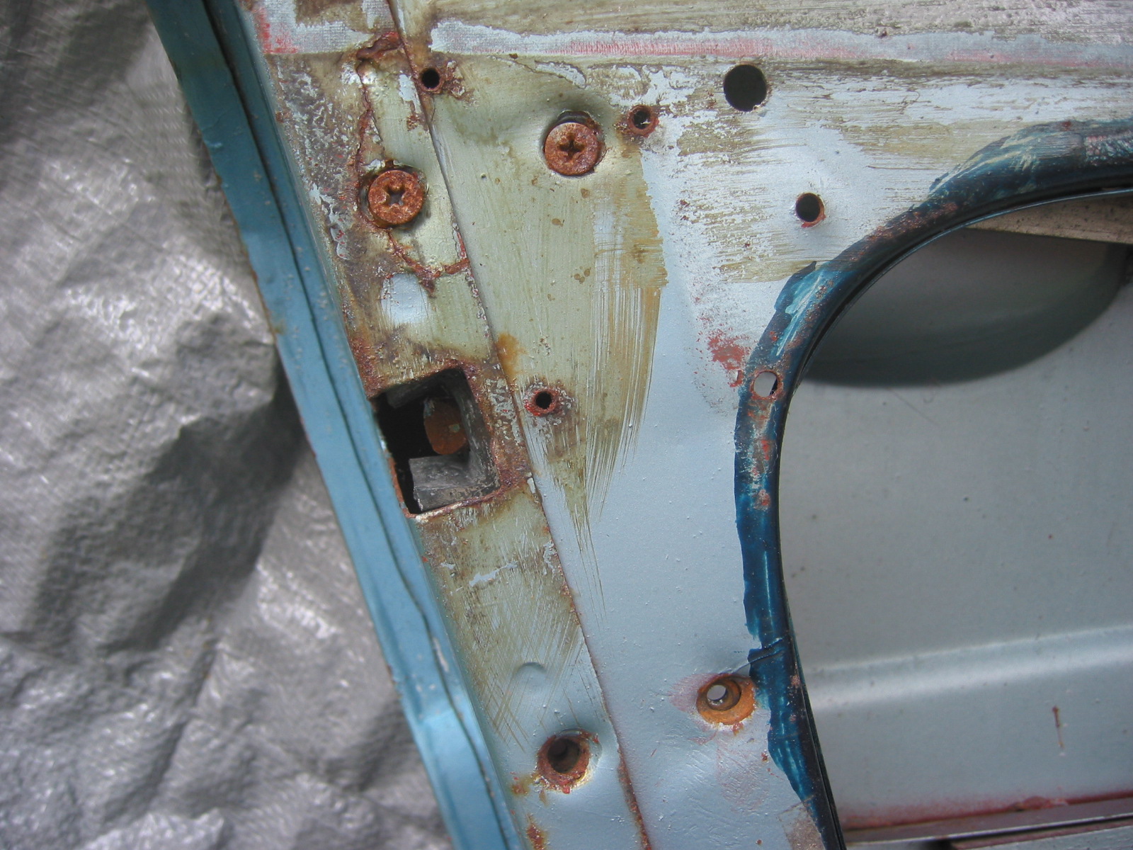
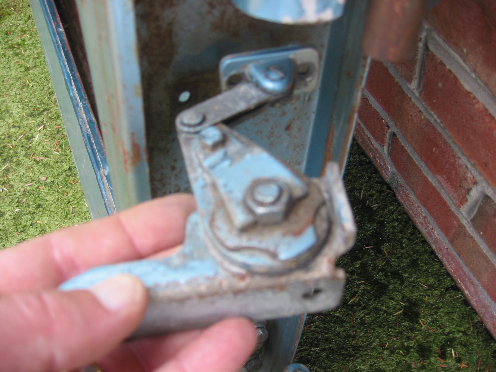
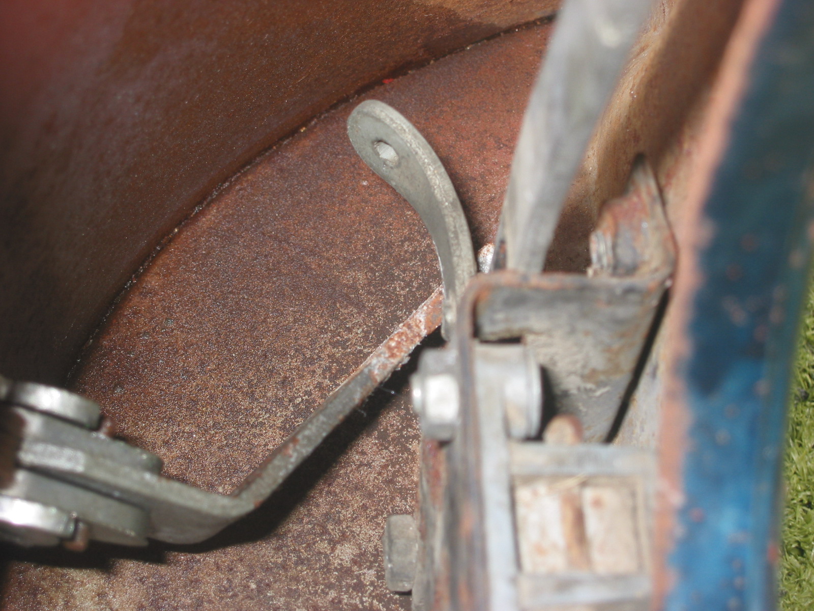
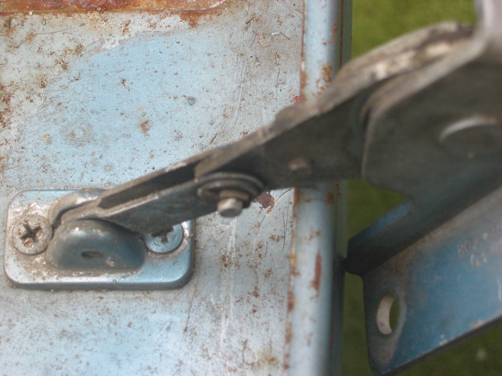
Grill brow mounting

Grill brow
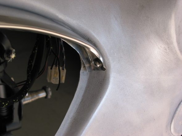
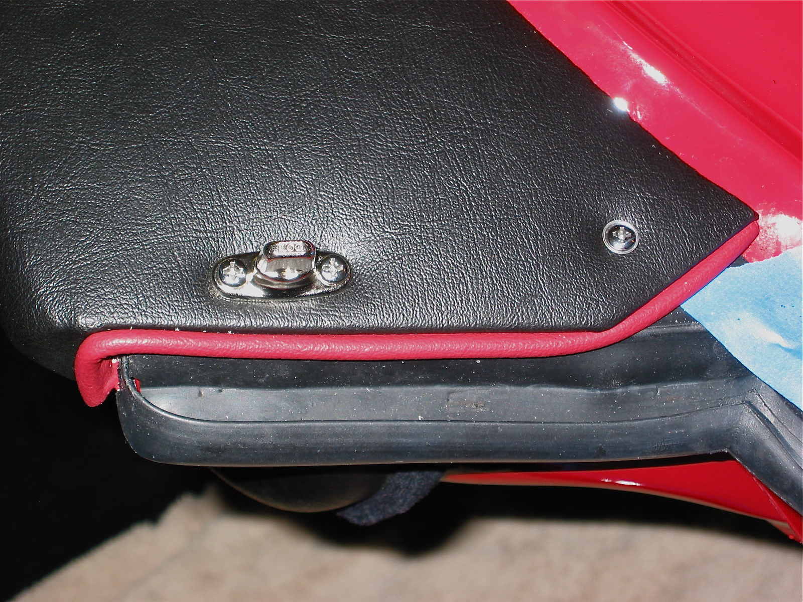
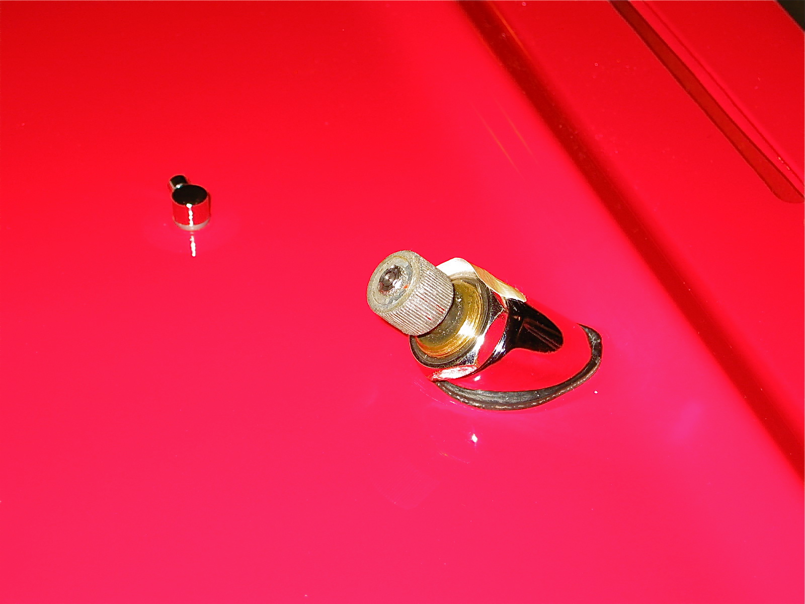
Grill exterior side mounting

Healey Shroud Motif
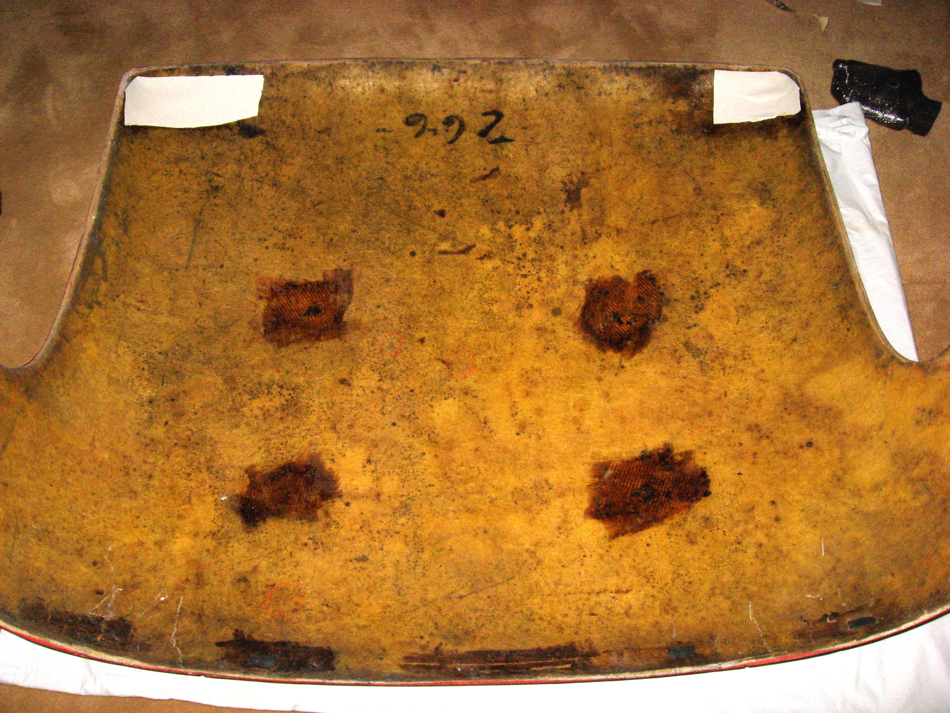
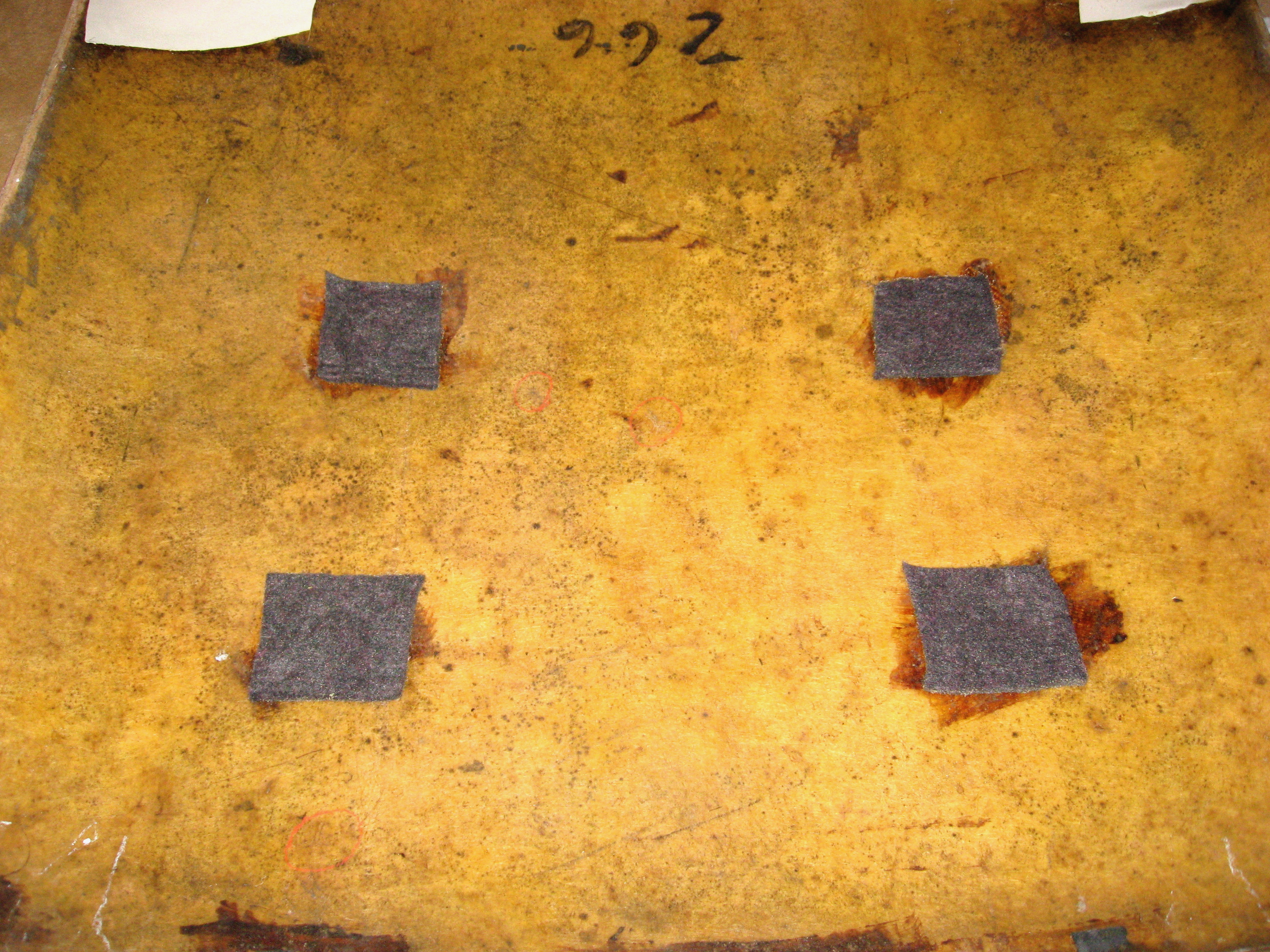
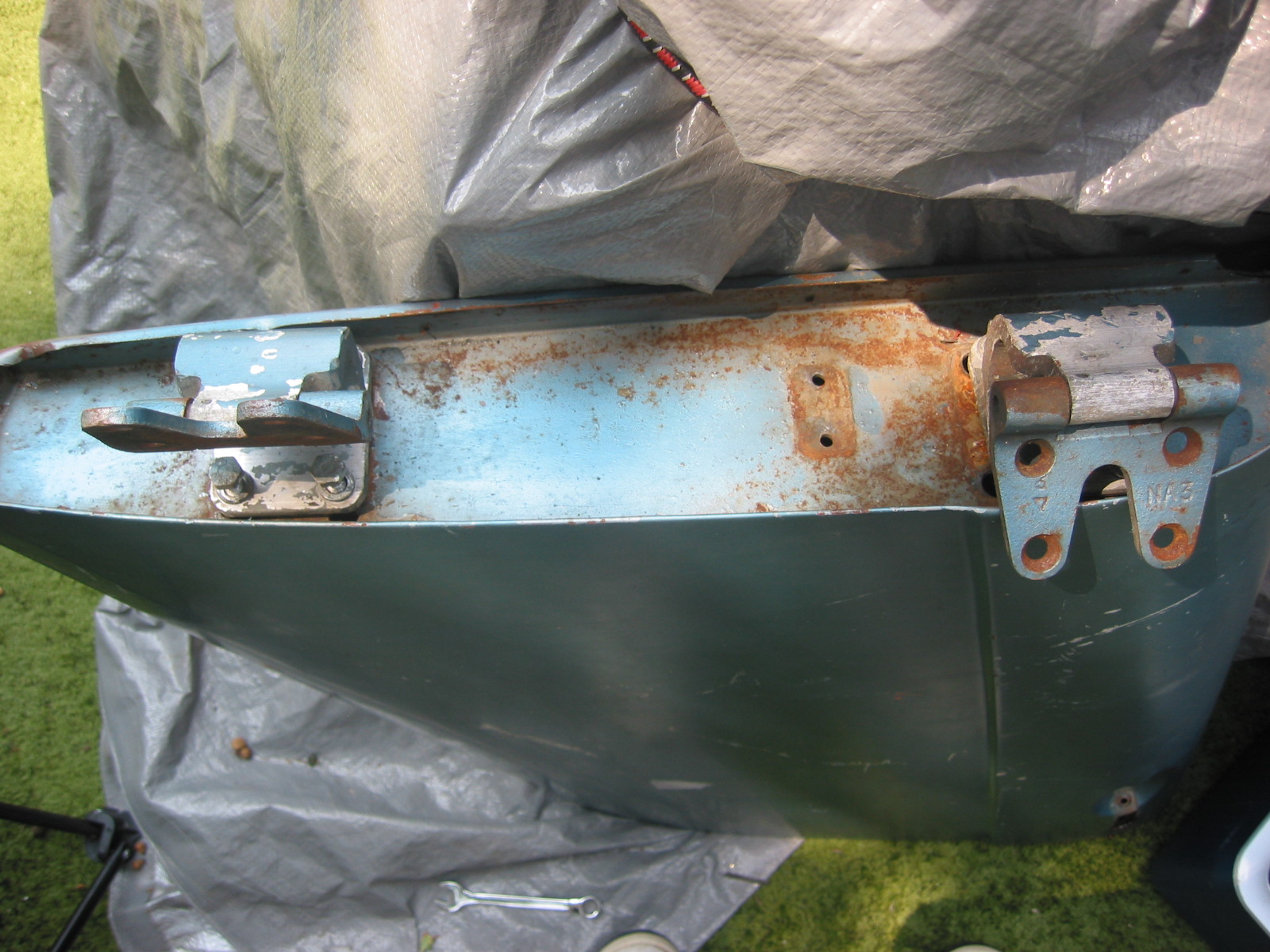
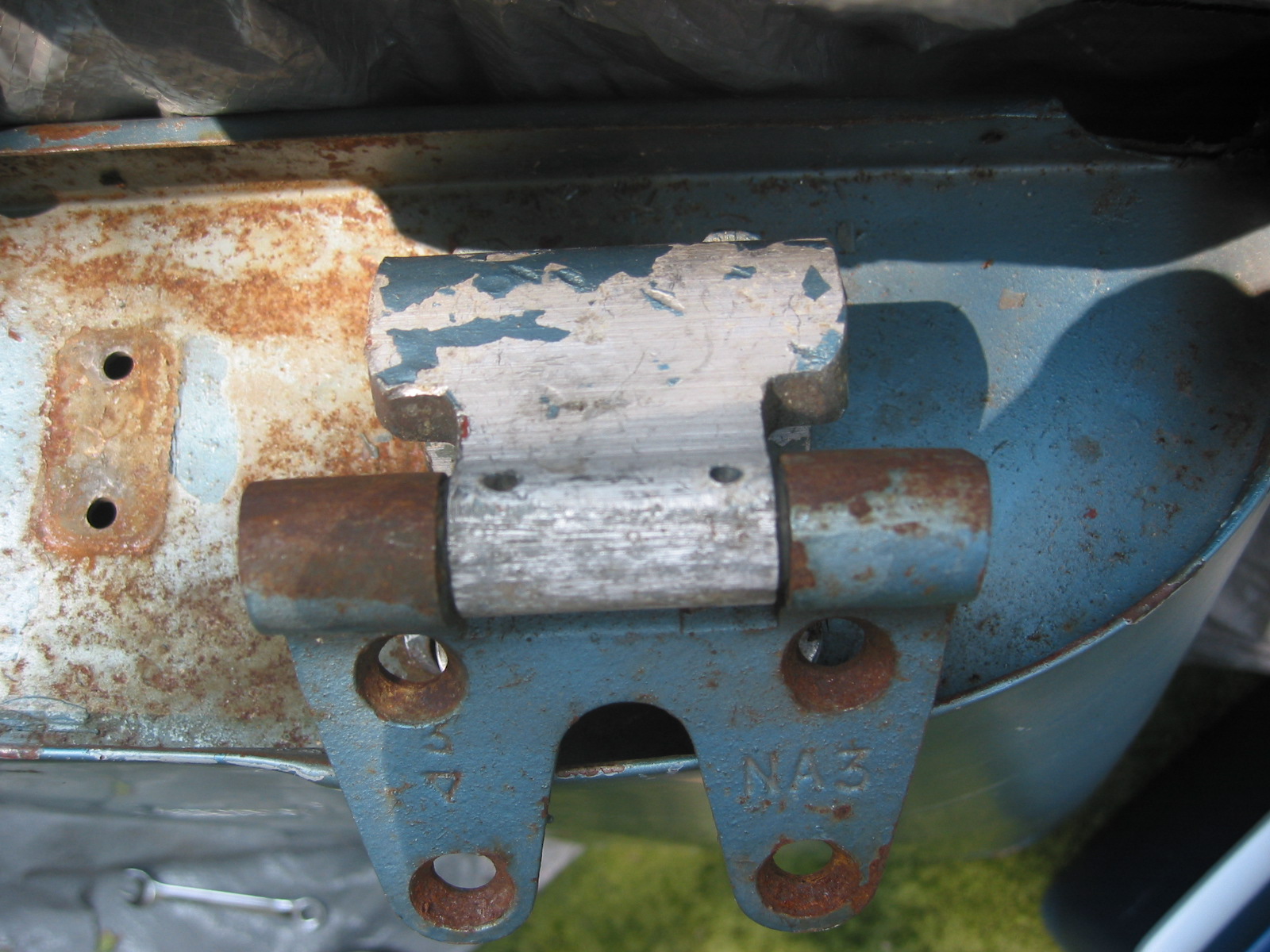
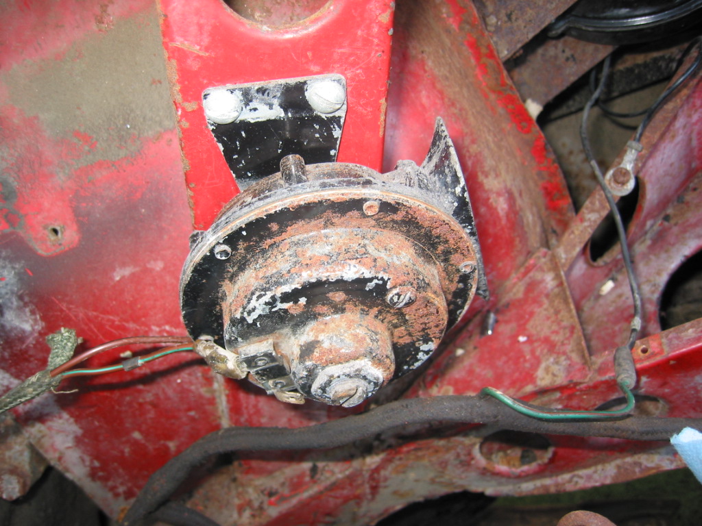
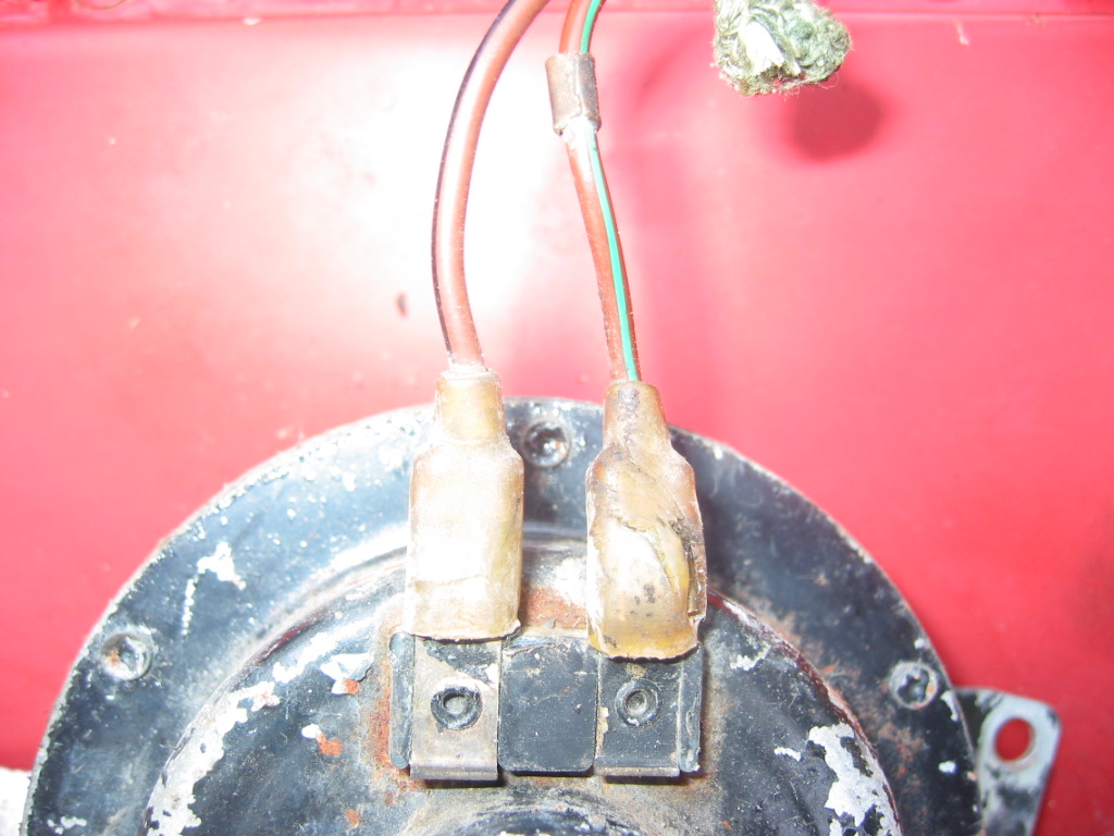
May 9, 2004
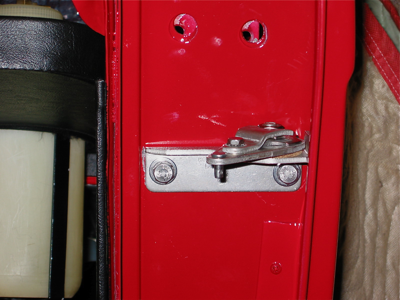
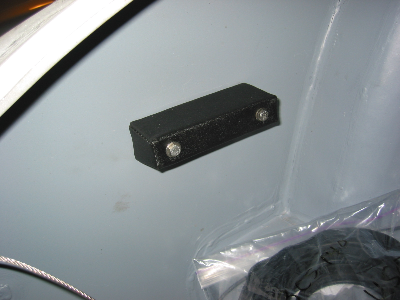
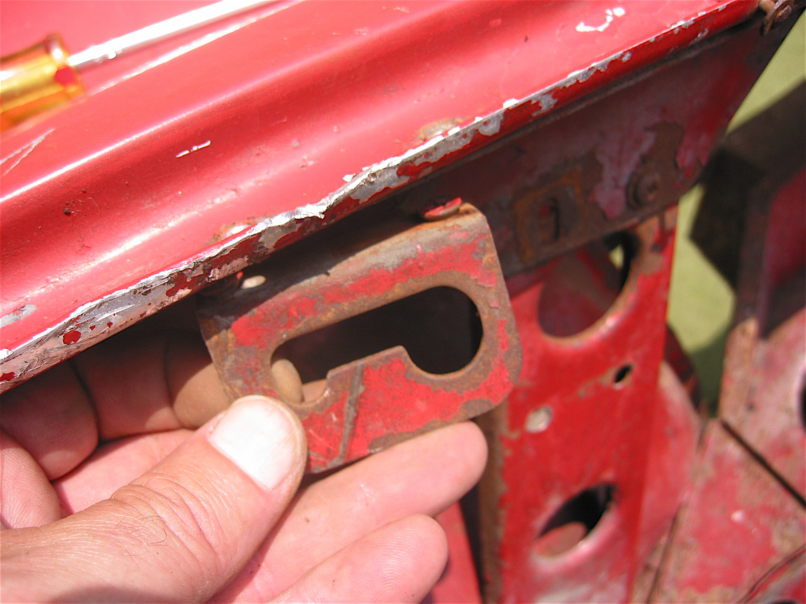
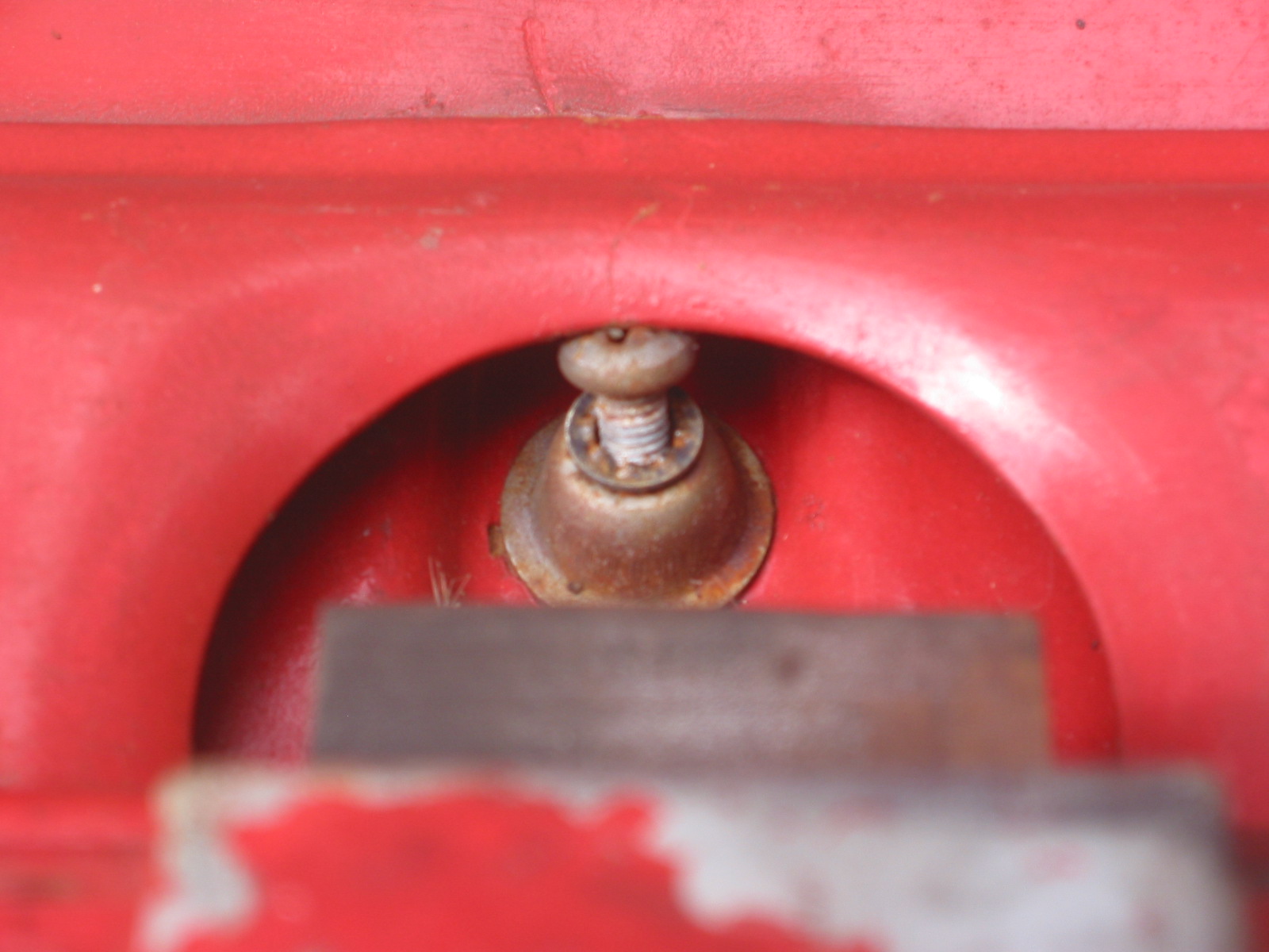
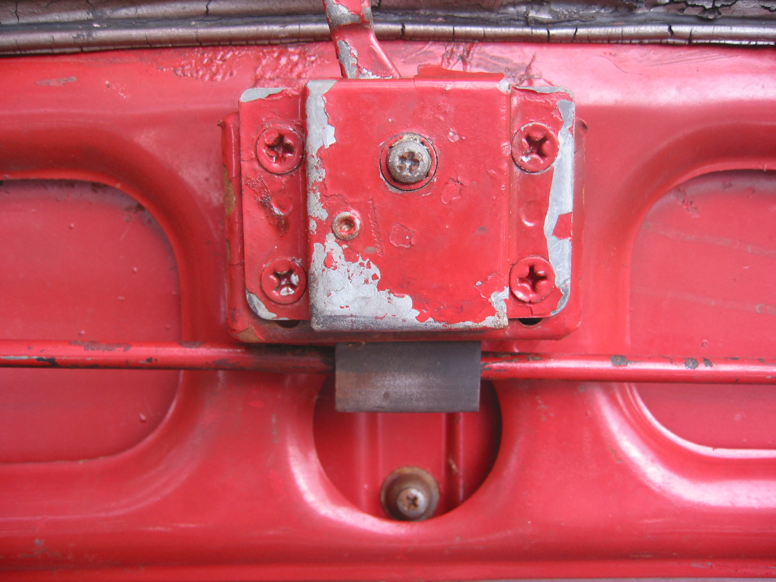
I borrowed Jeremy Turner’s cert nut pliers and installed cert nuts where the original fixed nuts were once located – light relay, insulation panels, dimmer switch, boot floor tie down staple and etc. Slow job but the nuts seem to work effectively. You drill a 9/32” hole for the #10 cert nuts and a 3/8” hole for the 1/4” cert nut. Then I installed the spare tire bump block on the left side of the boot wall. This block is supposed to use fixed nuts but I decided to use nuts with lock washers instead.
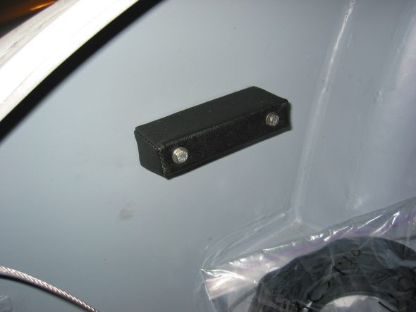
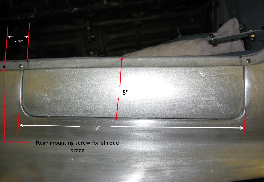
Spare Tire block
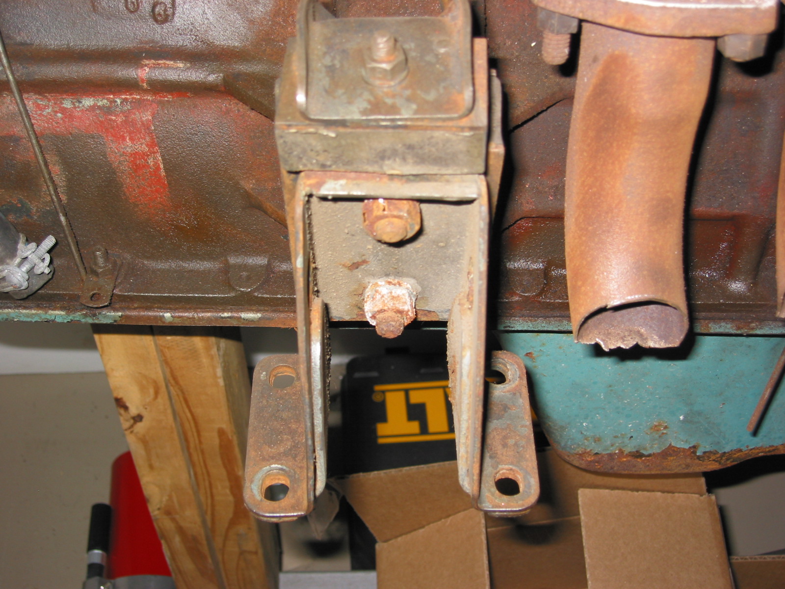
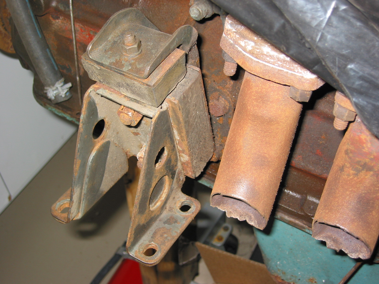
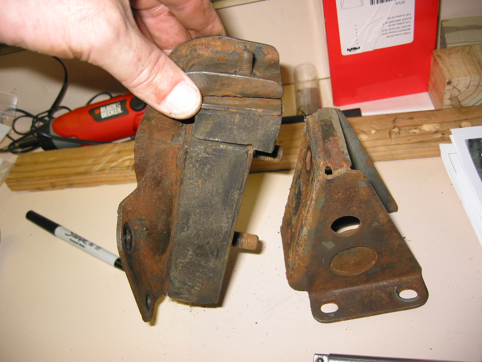
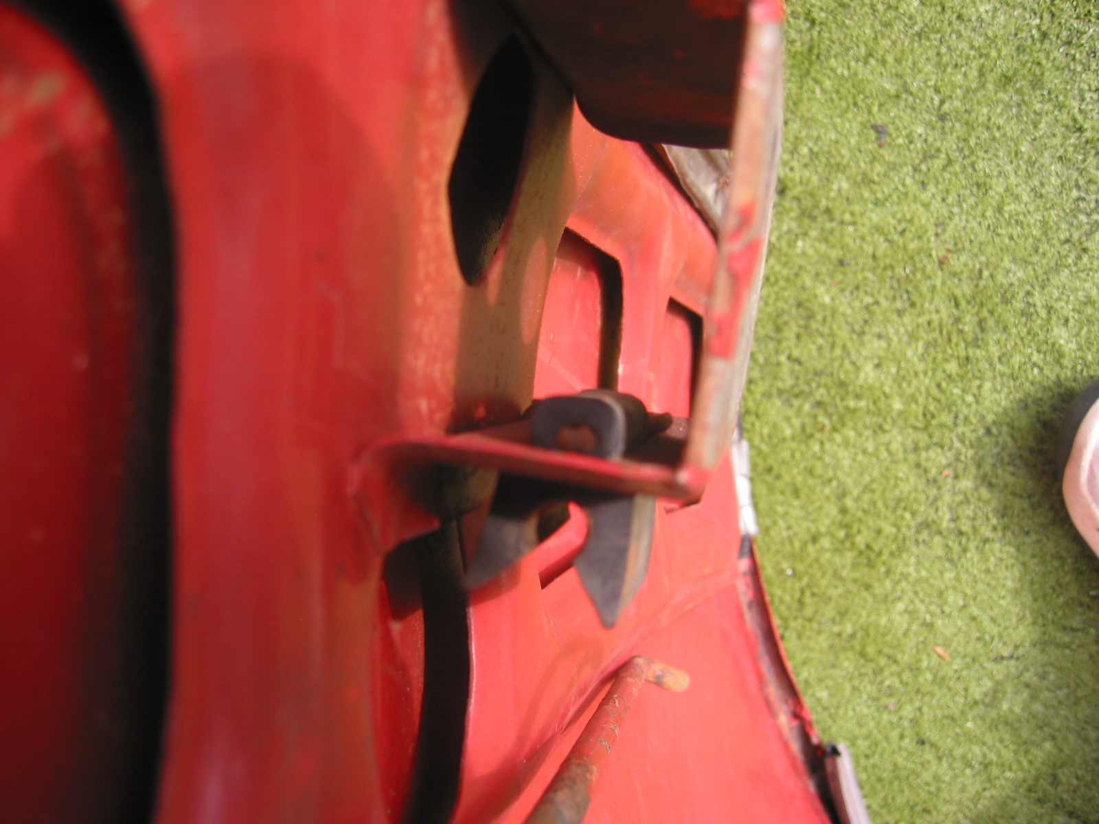
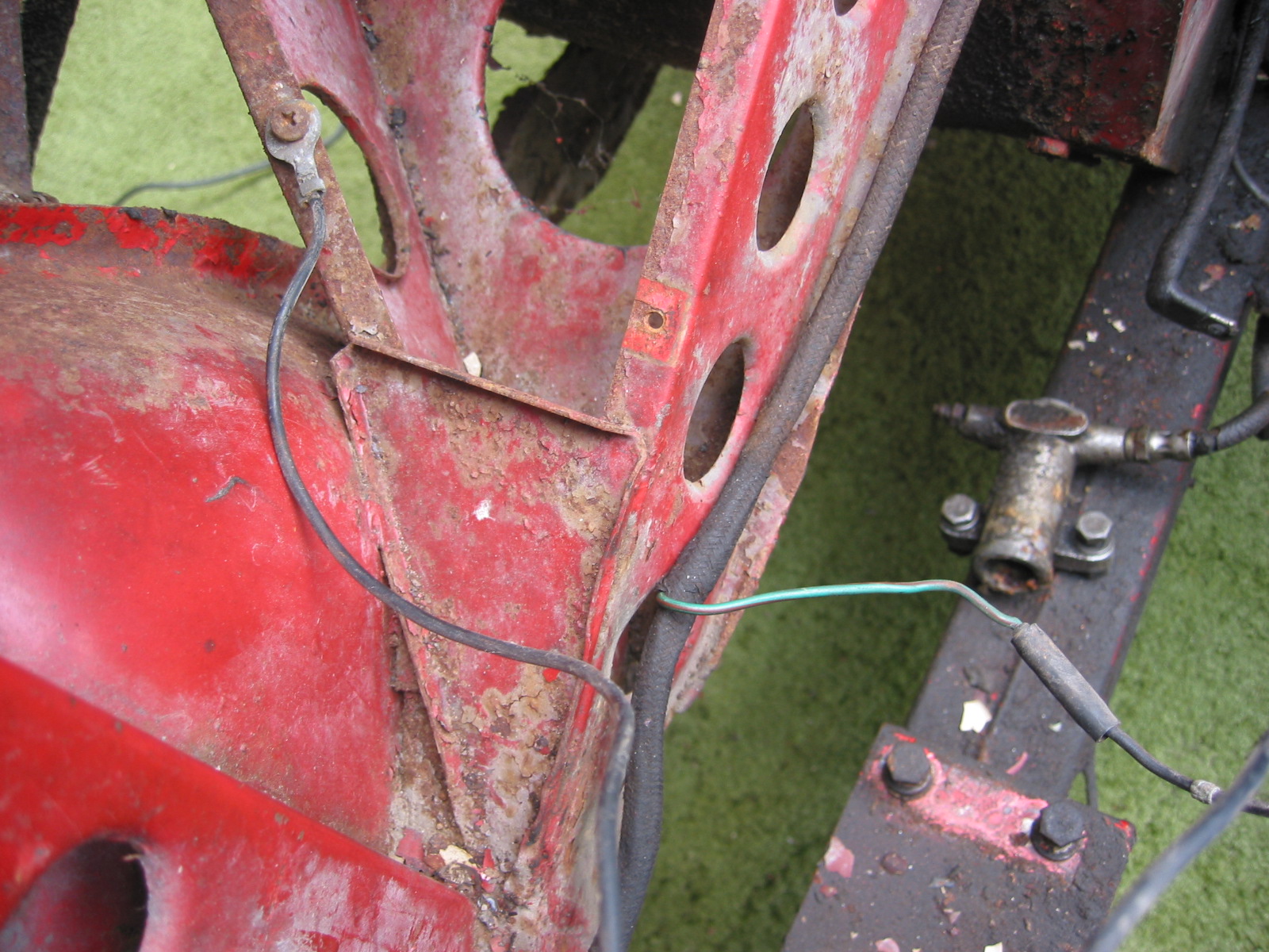
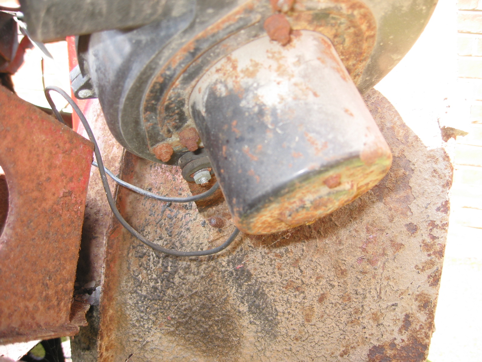
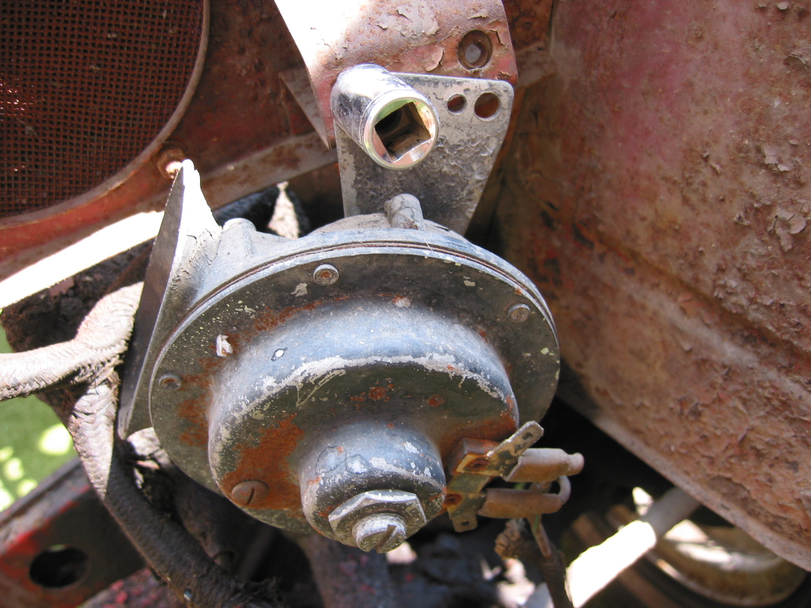
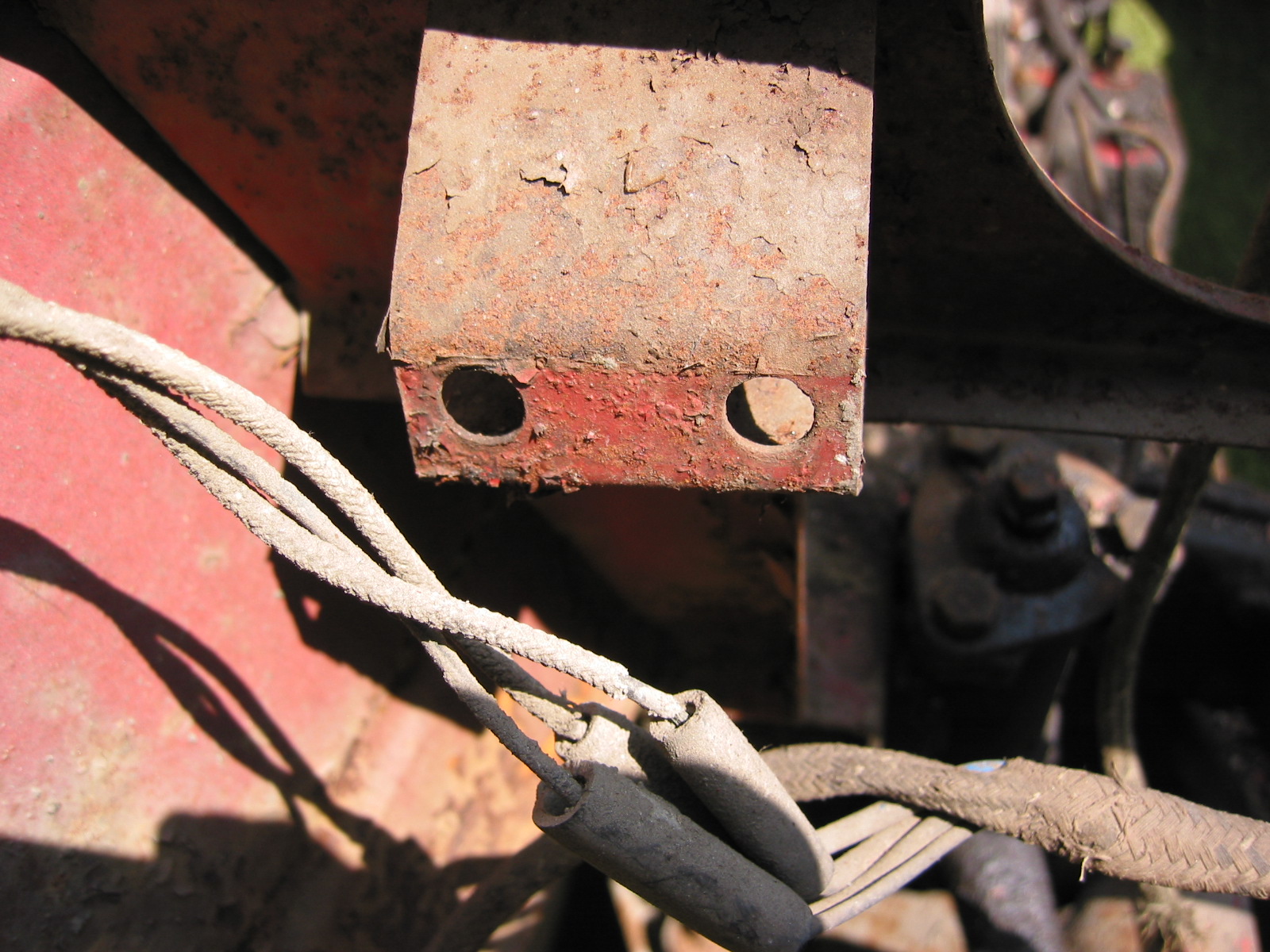
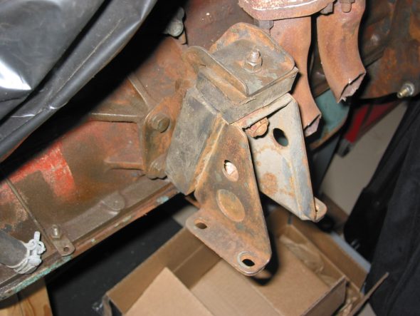
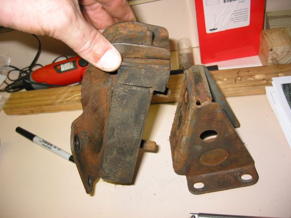
Motor Mounts – Removed the motor mounts from the motor to take to Jeremey’s for blasting and painting.

Motor Mount – Left 1
Motor Mount – Left 2

Motor Mount – Left 3
Motor Mount – Left 4
May 16, 2004
Front Suspension Again
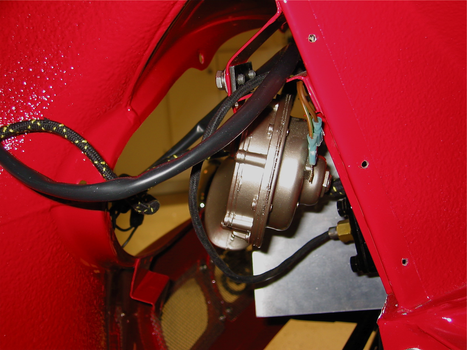
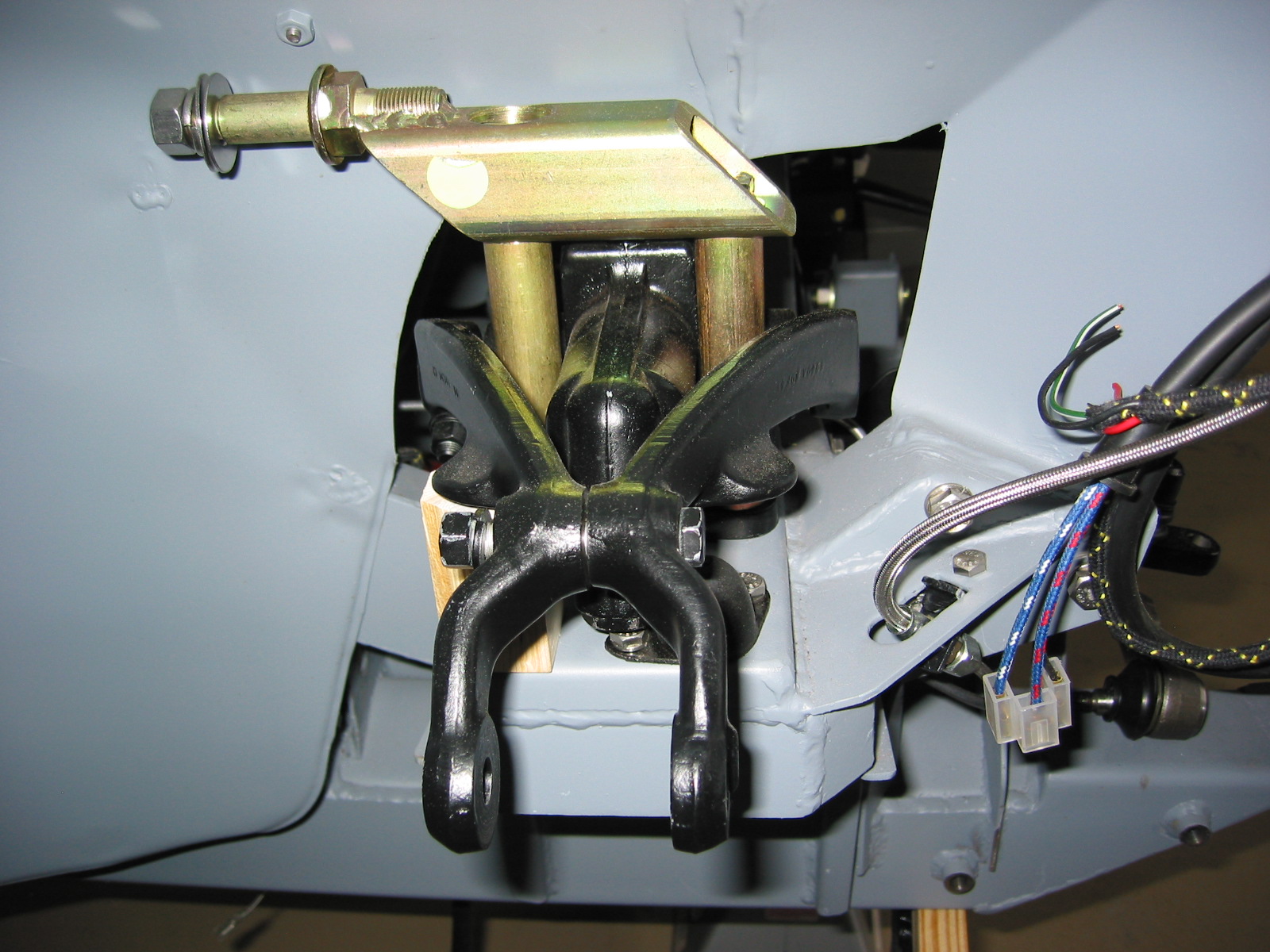
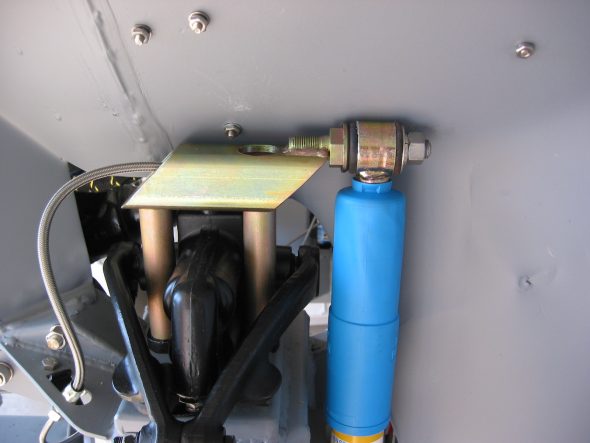
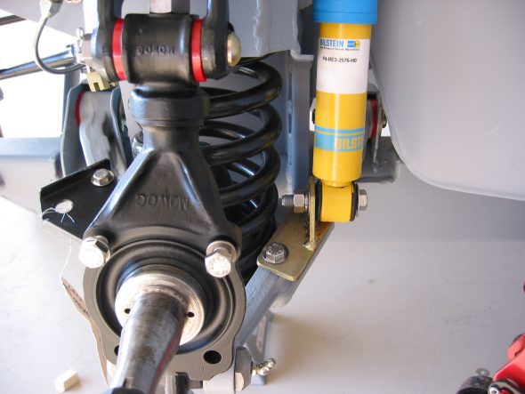
Front Shocks – Installed right front lever shock. Left the rear bolts loose and fit the Putzke tube shock mounting bracket to the front two mounting holes. Inserted the two inch wood block spacer to set the height of the suspension. Loosened the shock absorber arm bolt and nut so that the shock will receive the trunnion.

Putzke shock adaptor – right front
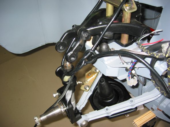
suspension install – right
Control Arm Base Plate – Used 3/8” threaded rods to install coil spring with plate
coil spring install
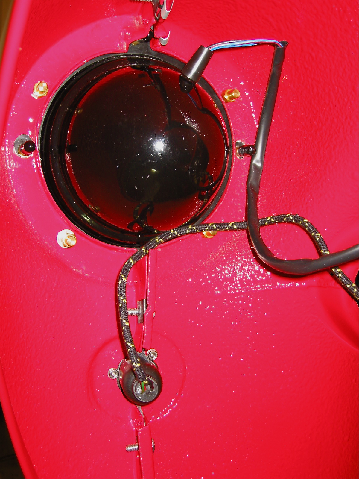
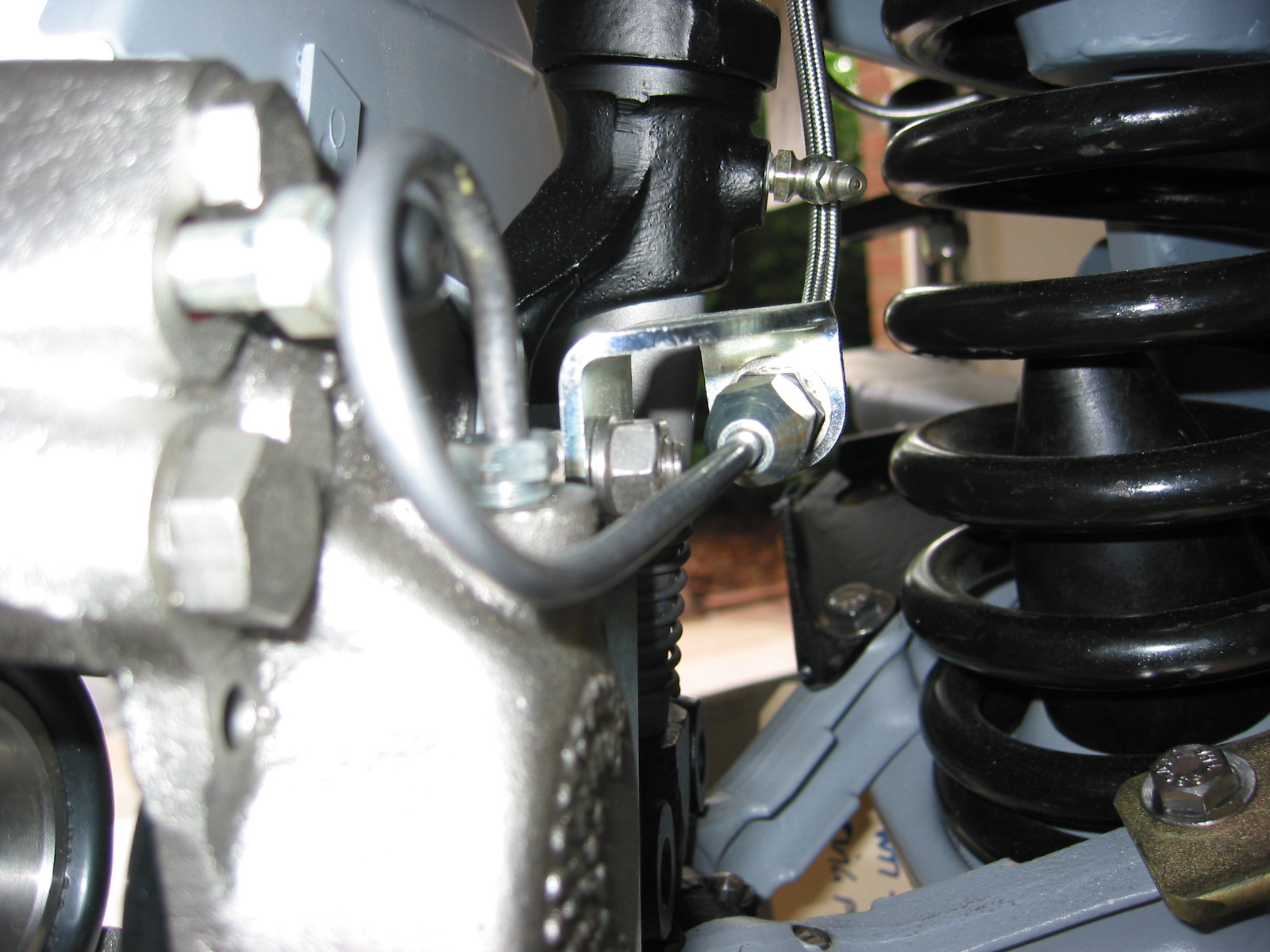
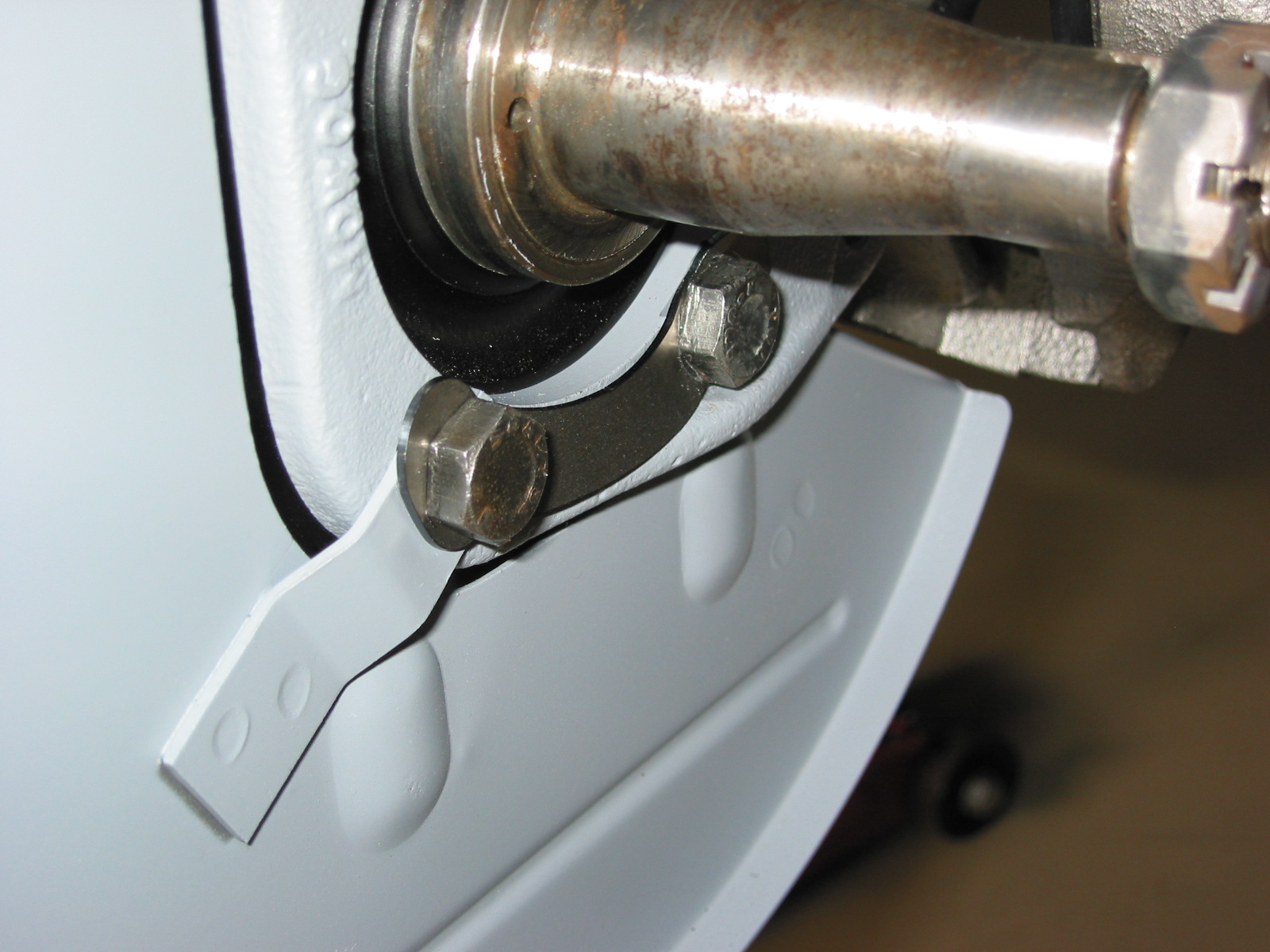
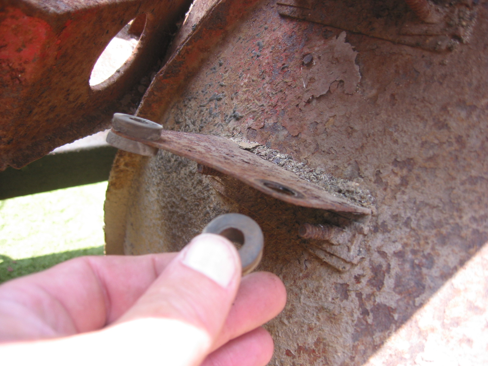
Disk Brake Dust Shield – Attached dust cover assembly to the front left spindle axle with two short bolts at top. I installed with the caliper attached but it will need to be removed before installing the rotor and hub. Attached new stainless steel brake hose from pipe to caliper bracket. Secured the left steering arm to the back of the swivel axle and used the tab washer to lock both bolts.
Dust shield – left
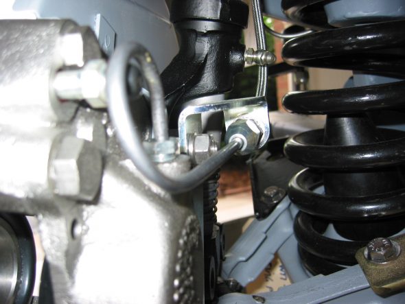
Brake hose connection left front
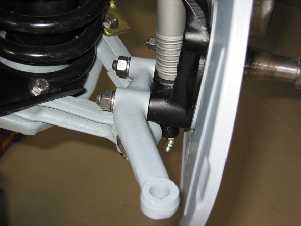
Steering arm – left installed
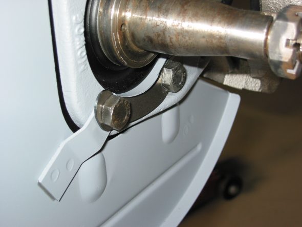
Tab washer on suspension
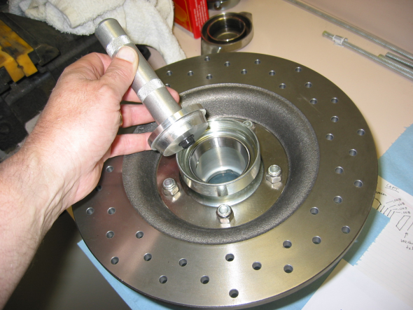
Front Brake Rotors and Hubs – Fastened rotor disk to the hub extension with 5 nylock nuts. Placed bearing races in the freezer so they would be easier to install in the front hub extensions. Then inserted inside bearing race with proper driver with application of a hammer!, being careful to keep the race/driver straight. Turned the hub over and did the same procedure with the outside bearing race.
Inside front bearing race install
Left front inside bearing – 126-000 GHB105
SET 6 LM67048 – LM67010
20031255
Left front outside bearing – 620-234 GHB182
07196
20030322
Left front bearing race- 620-231
07087
20030522
Right front inside bearing – 126-000 GHB105
SET 6 LM67048 – LM67010
20031255
Right front inside bearing – 620-234 GHB182
07087
20030522
Right front bearing race – 620-232
07196
20020422
Front Hub Bearings – I followed directions from Bruce at Healey Surgeons and put 90 weight oil on the inner bearing and offered it up to the spindle. The oil will provide protection from damage due to bearing running dry but at the same time, not give a false reading when trying to shim the bearings.
I then placed the spacer (cone) on the spindle followed by the hub extension. I then put an oil filled outer bearing on the axle followed by the tab washer and castle nut. The seal and shims were NOT added at this stage. The nut was tightened down to seat everything and then the works were disassembled. It can be difficult to get the outer bearing and the tab washer off – I used a magnet that worked quite well.
I then put the inner bearings, the spacer and selected shims on the axle. Starting with the thickest one .030, then .010, .050, .030, ( one of each ). I then put the hub extension on the axle followed by the outer bearing, tab washer and nut. I tightened to 40 lbs of torque and determined if one of the castle nut slots lined up with the hole in the axle for the split pin. Need to take care that the shims are all the way up on the shoulder of the spindle axle so that they do not get mangled when the nut is tightened. The final proper adjustment is correct when you can tighten on the nut and the wheel does not show any reduction in ease of turning with no play.
If it drags when you tighten the castle nut, then you need to add shims. If it is to loose, you need to remove the shims, When it is correct, re-tighten to the correct specs. At this point, the hub should be turning freely, with no end float and no pre-load.
Once you are satisfied that you have the bearings set up correctly, then remove everything. Make sure you keep track of the shims! Now pack the wheel bearings with wheel bearing grease and install your front seal (don’t forget this step). You need to place the spacer in the hub extension and bearings in first, and then reassemble unit.
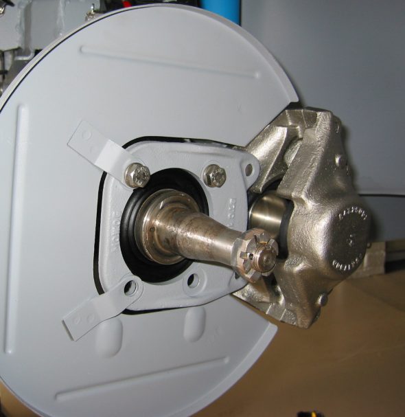
Place the split pin through the hole in the spindle axle, and then pull one tab of the pin forward and bend it back over the axle end. Then push the grease cap on to the axle ( do not fill it with grease). Reinstall brake caliper.
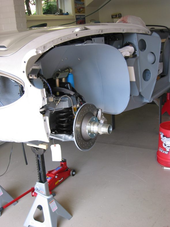
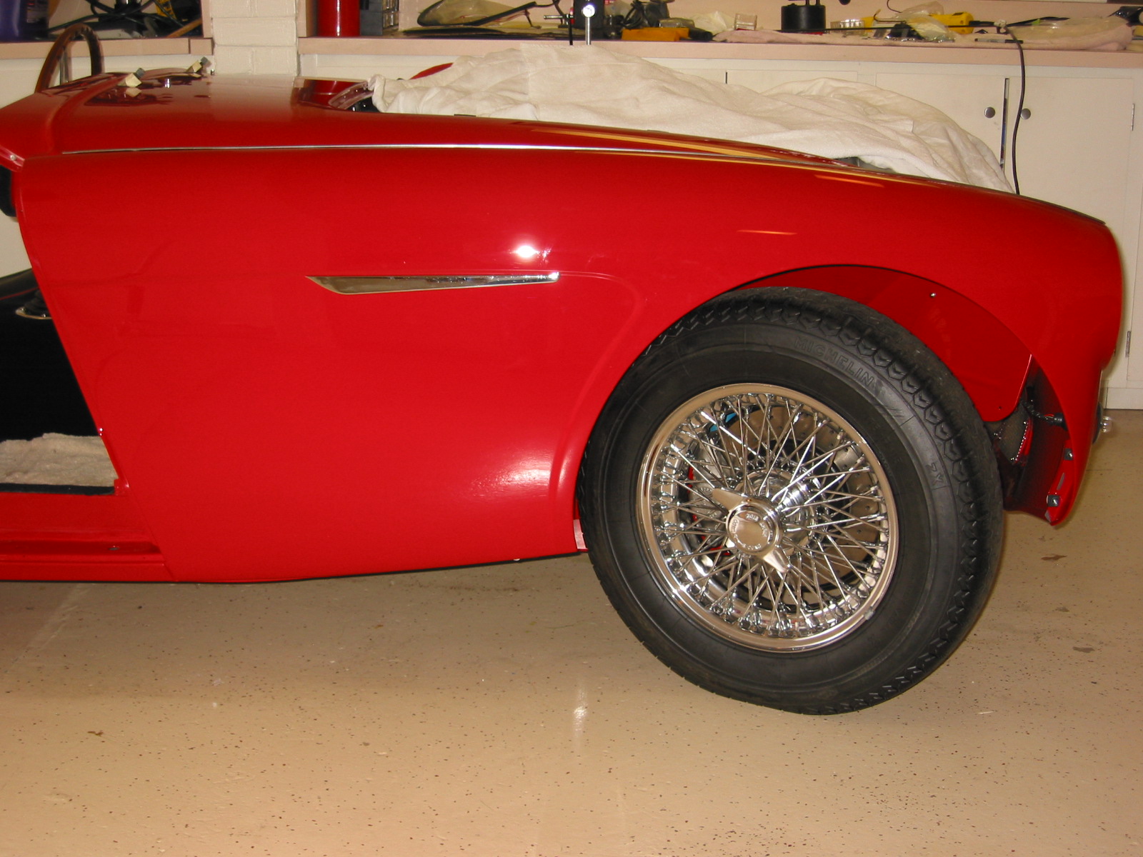
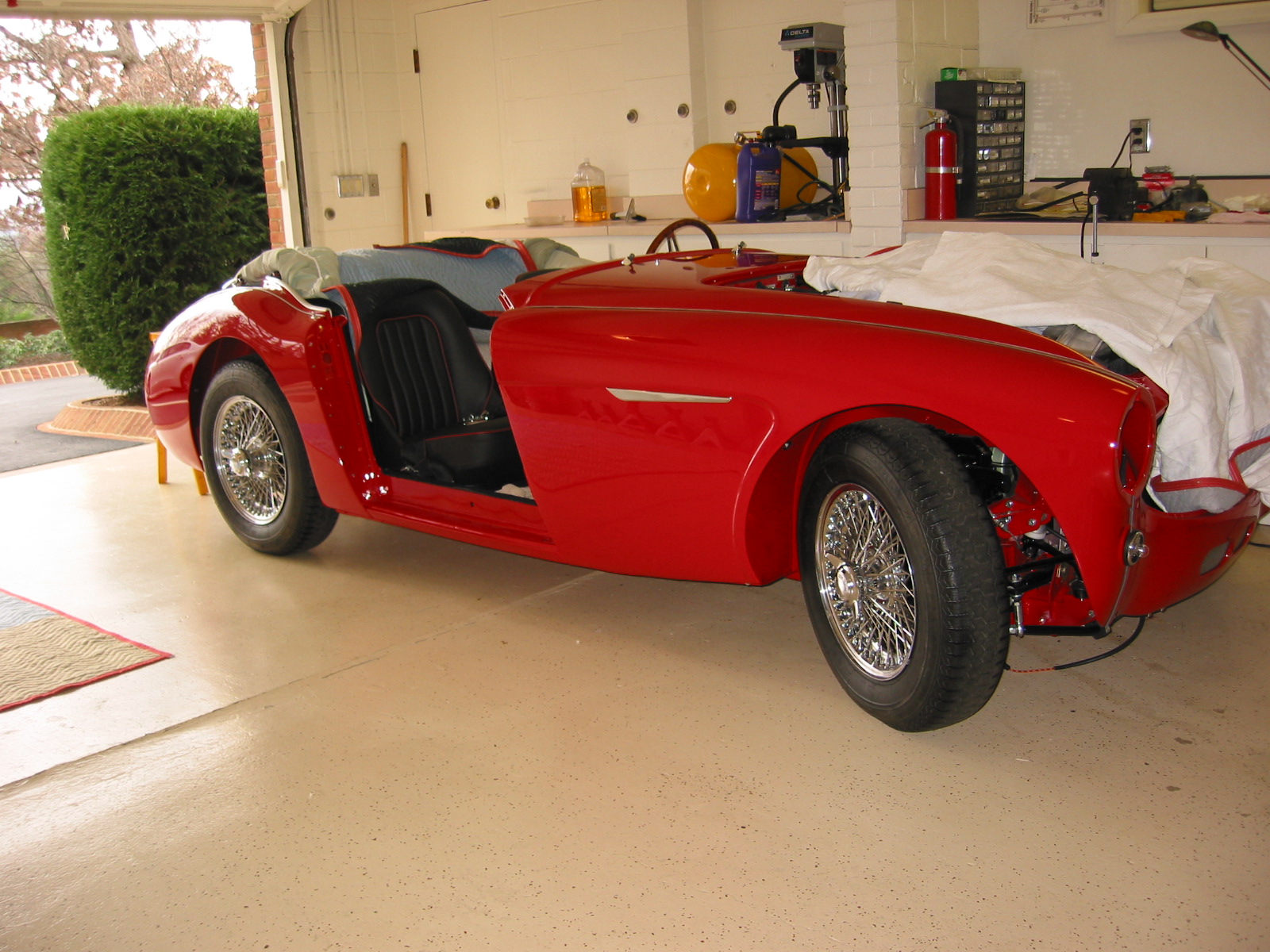
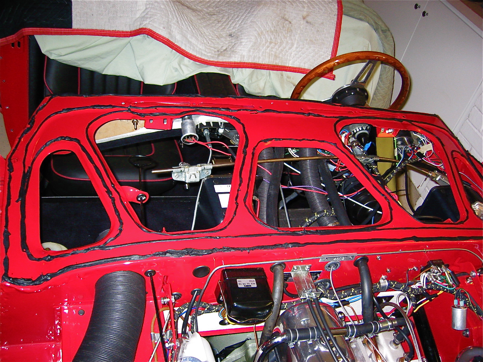
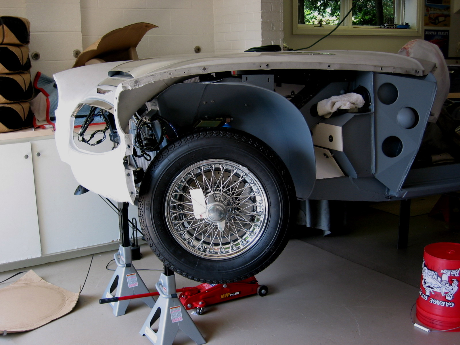
Front Suspension Installed

Front suspension installed 2