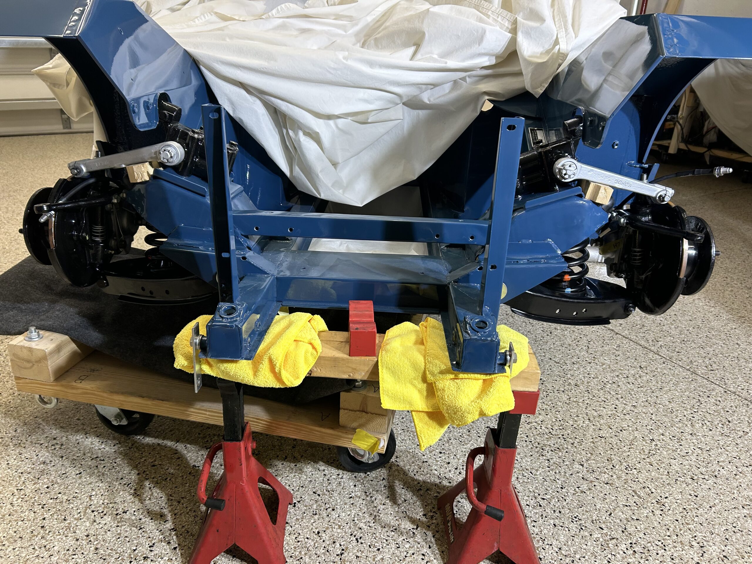
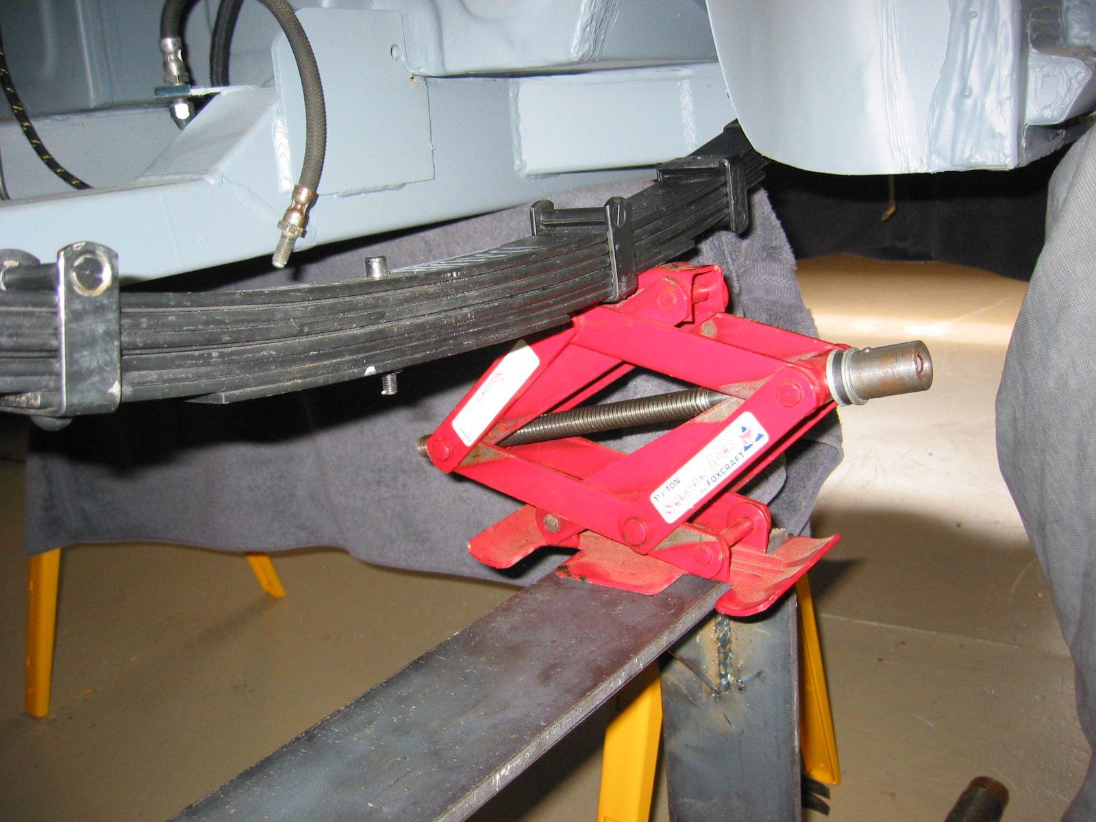
Working on the front suspension of the Mark 2 is made easy for the hobbyist, because it is possible to completely reassemble the front suspension apart from the vehicle and then “offer it up” to the frame of the car with a jack or two. It is certainly more convenient to assemble the components on a work bench or table than working under the car!
The image below from the Jaguar Mark 2 Models, Service Manual depicts the process.
“The front suspension assembly is attached to the body underframe at four points. The two longitudinal members are attached to brackets at the front end of the chassis side members via flat rubber/steel bonded mountings. The transverse member is attached to the chassis side members via two “V” shaped rubber/steel bonded mountings.”

Removal of the Front suspension Assembly
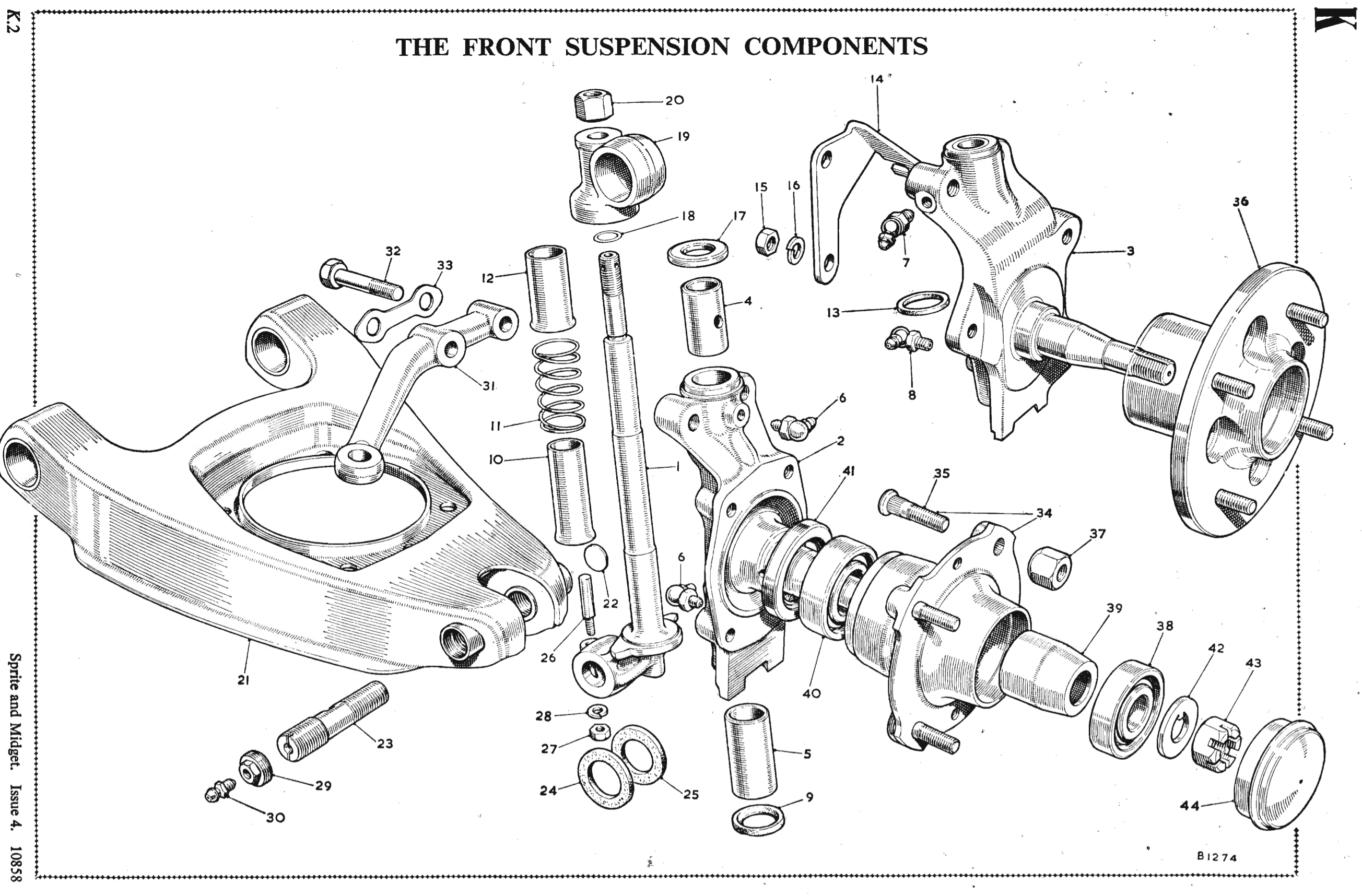
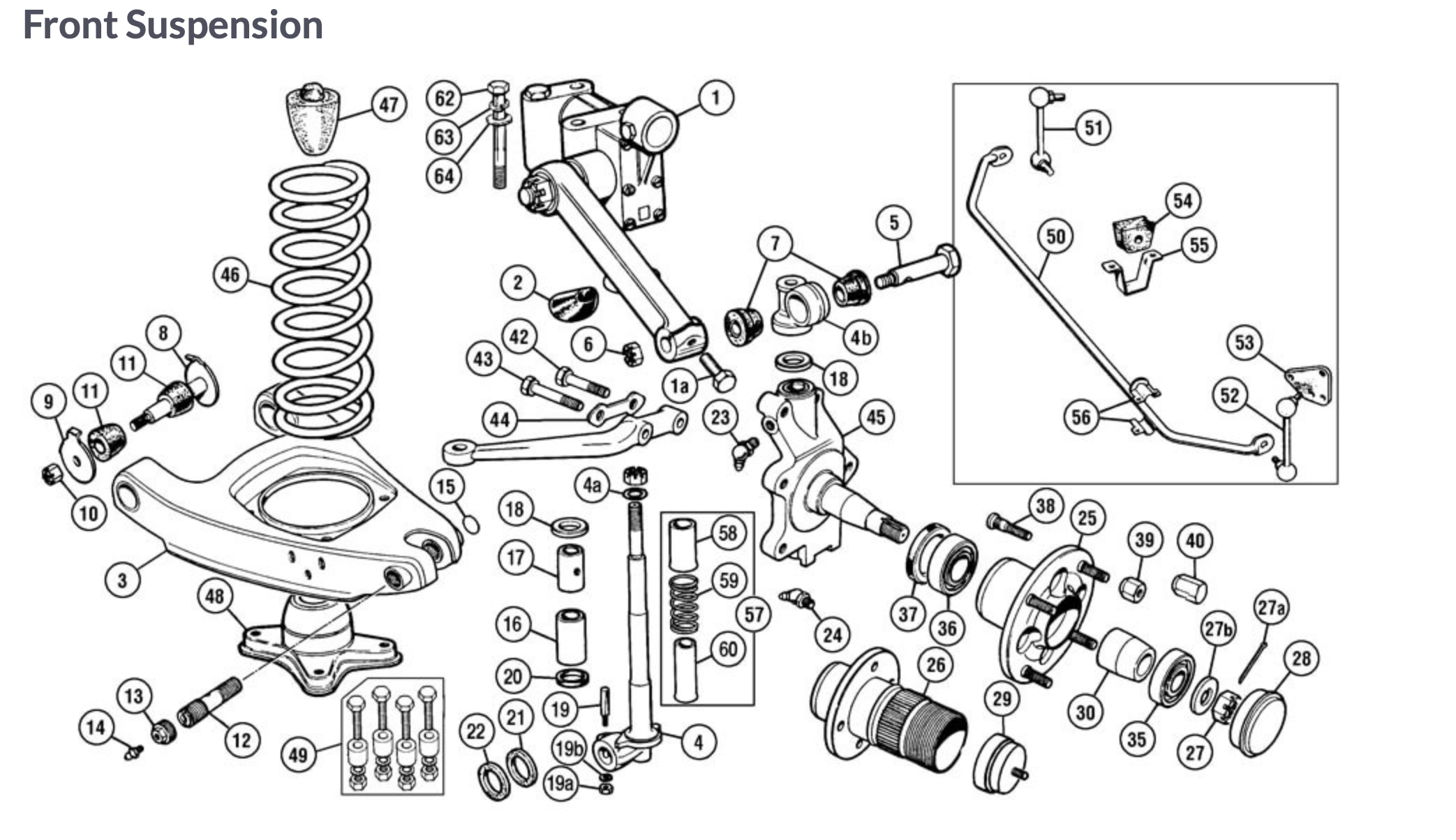
Plate number 62 in the Spare Parts Catalogue for the Mark 2 Models is very helpful in identifying suspension parts.

Front Suspension Schematic
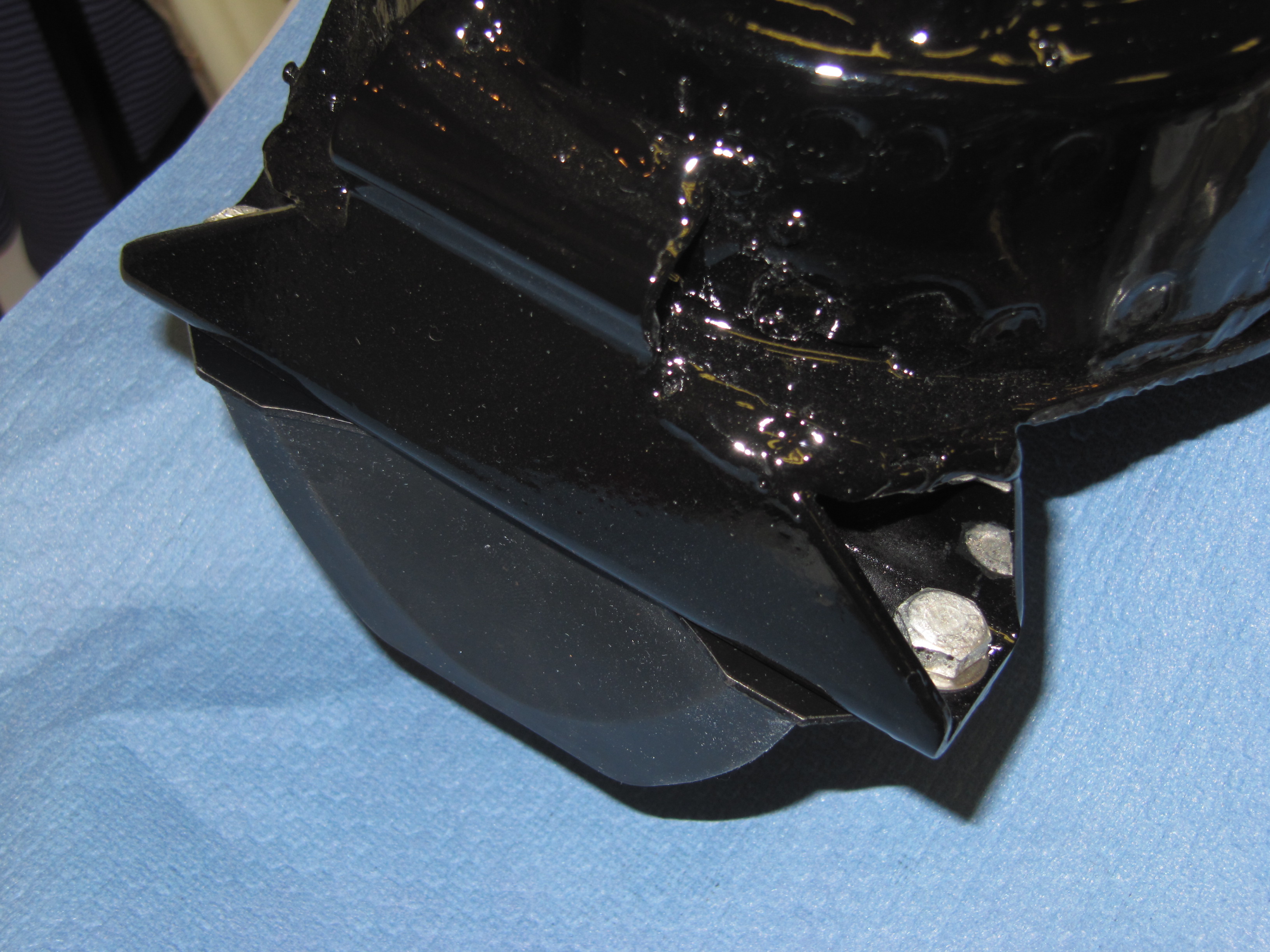
The process begins with the Front Suspension Cross Member. This component is too large for my media blast box, so I took it to a commercial blaster for proper cleaning and then on to Premier Auto Body in Harrisonburg, VA for sealing, priming and paint. All front suspension parts are painted gloss black.

Front Suspension Cross Member
All of the smaller components of the front suspension were cleaned up in my own blast box and then painted at Premier. I have used my blast box for about a year now and I continue to be amazed at the way in which an old greasy and rusty part can be brought back to life.
Mounting Brackets for Cross Member to the Frame
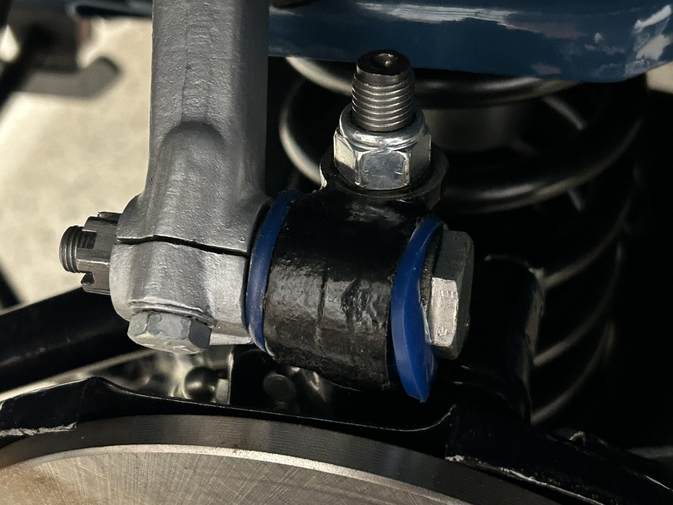
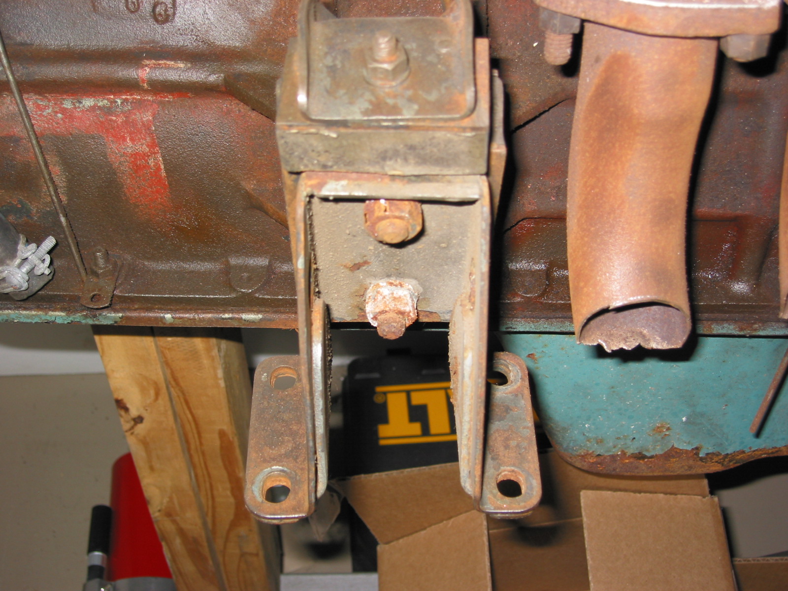
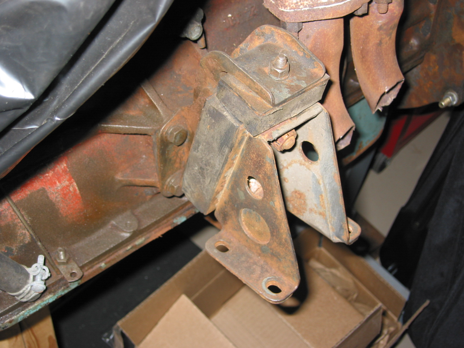
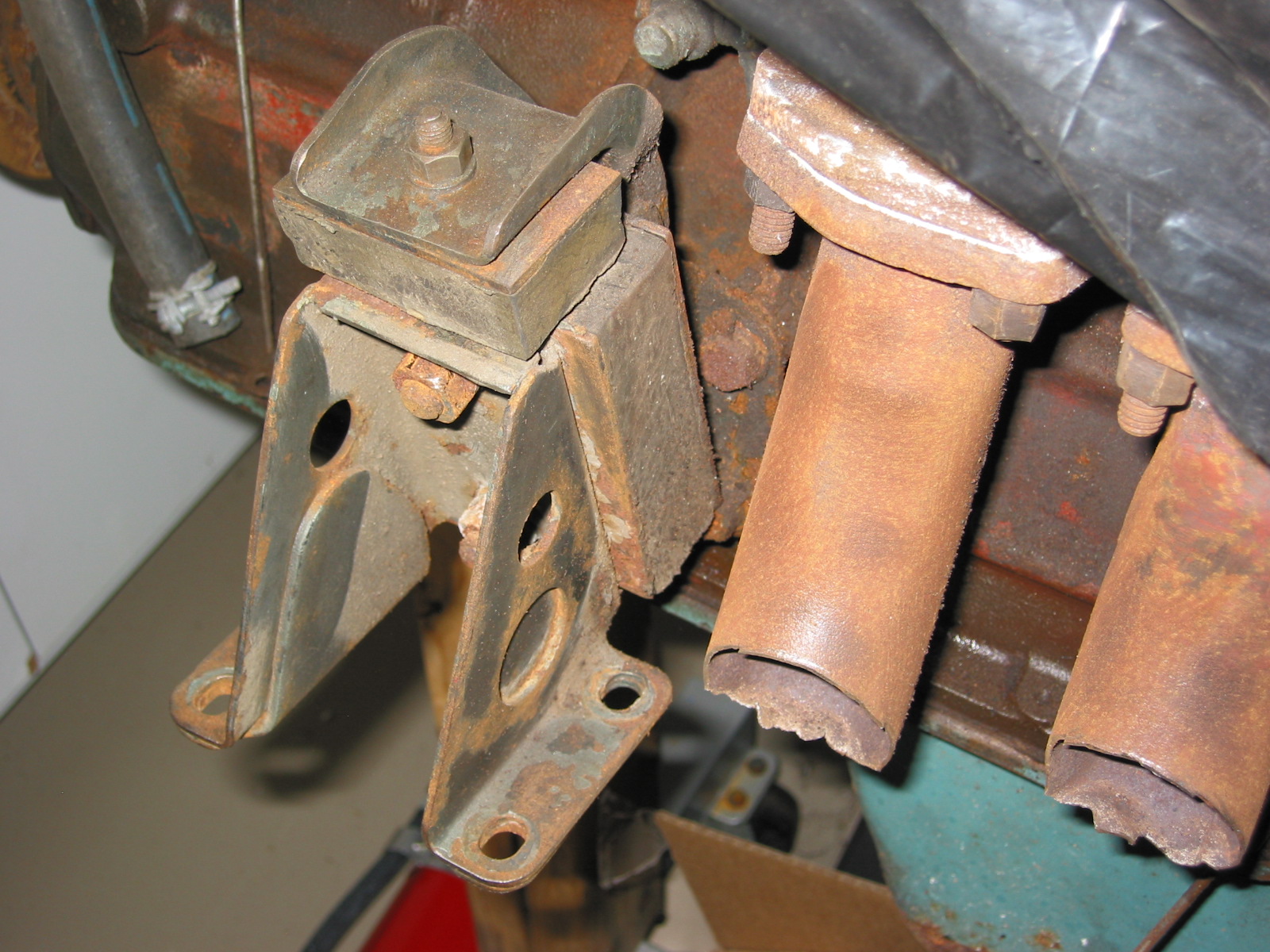
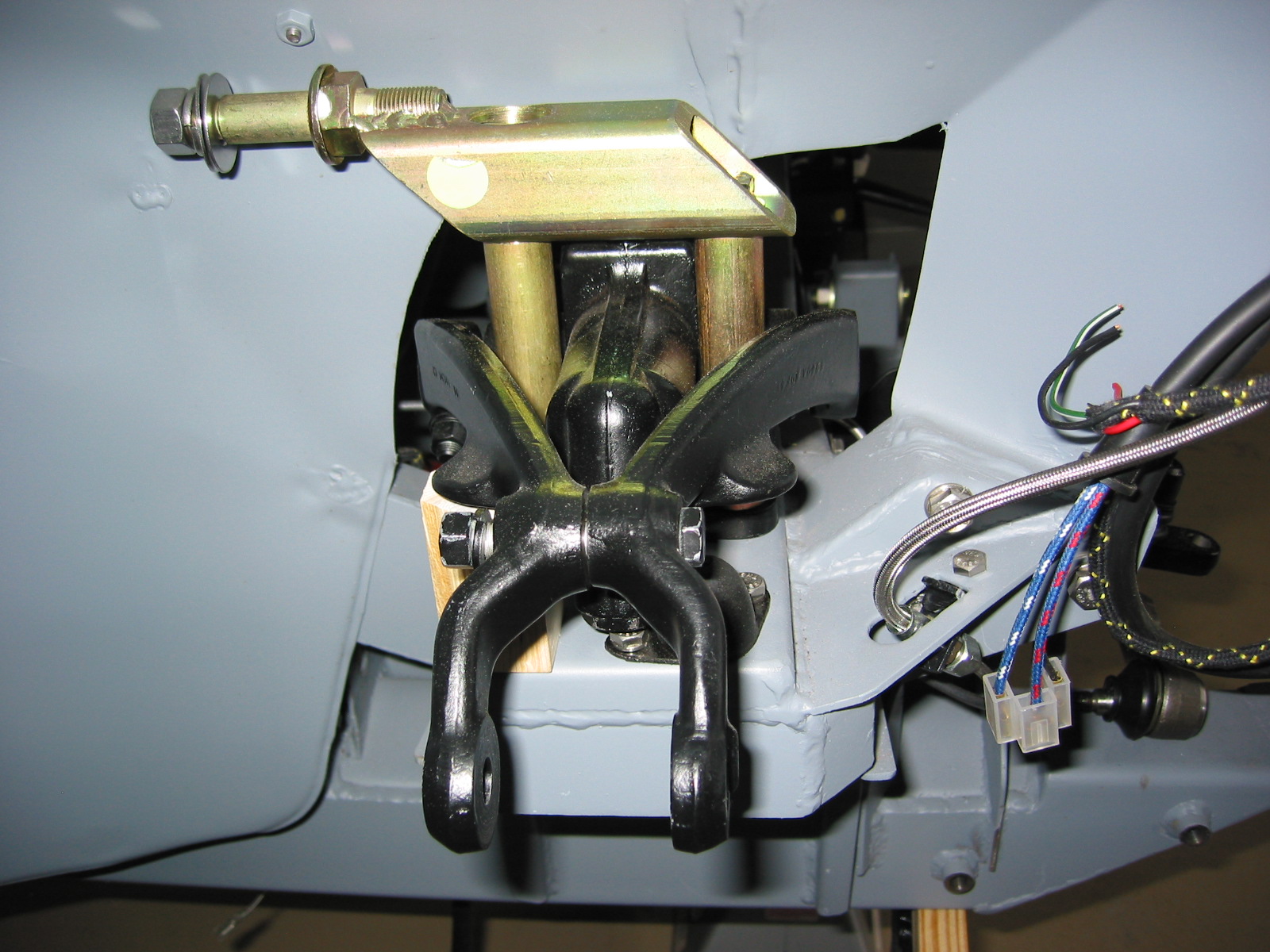
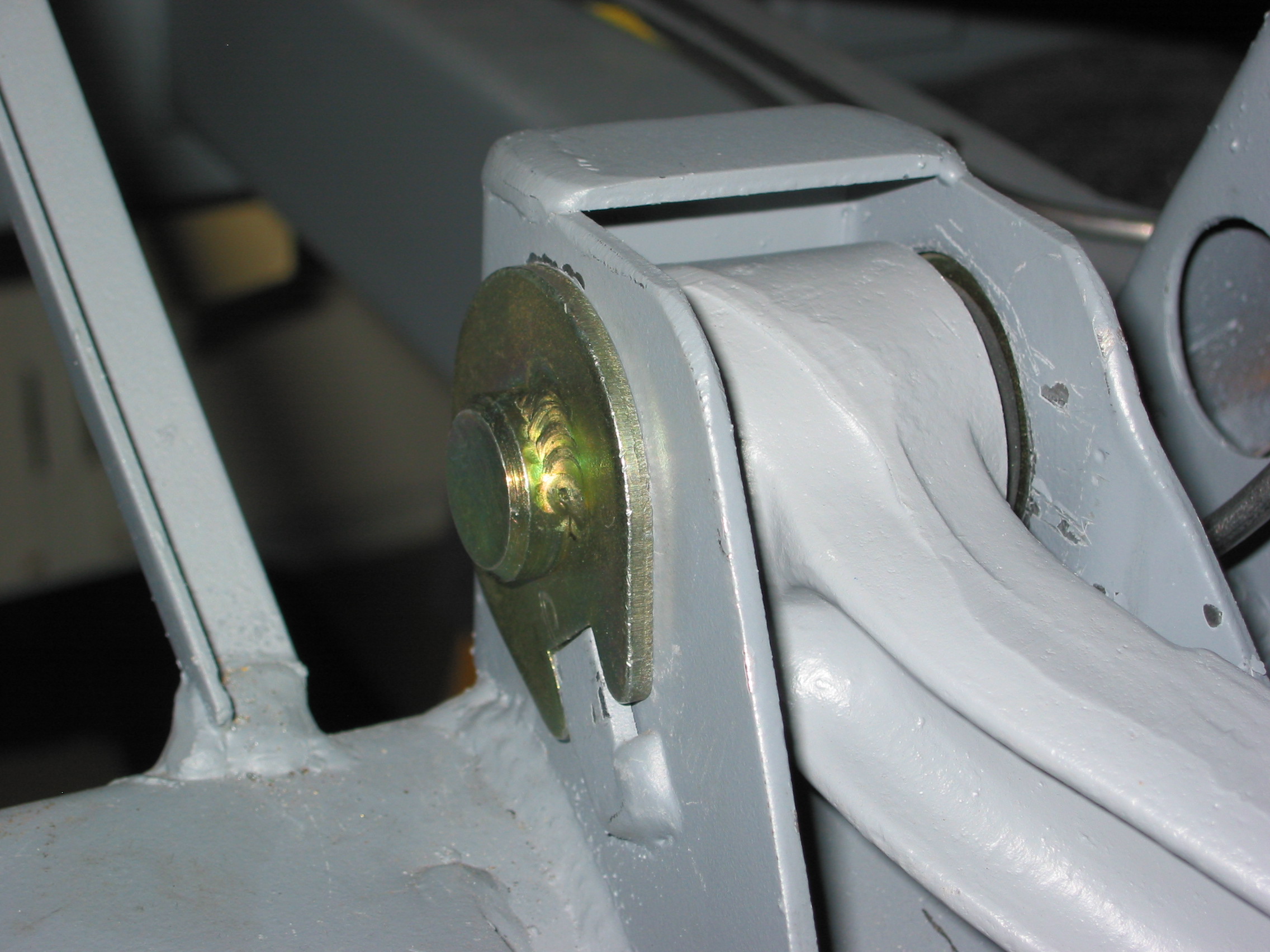
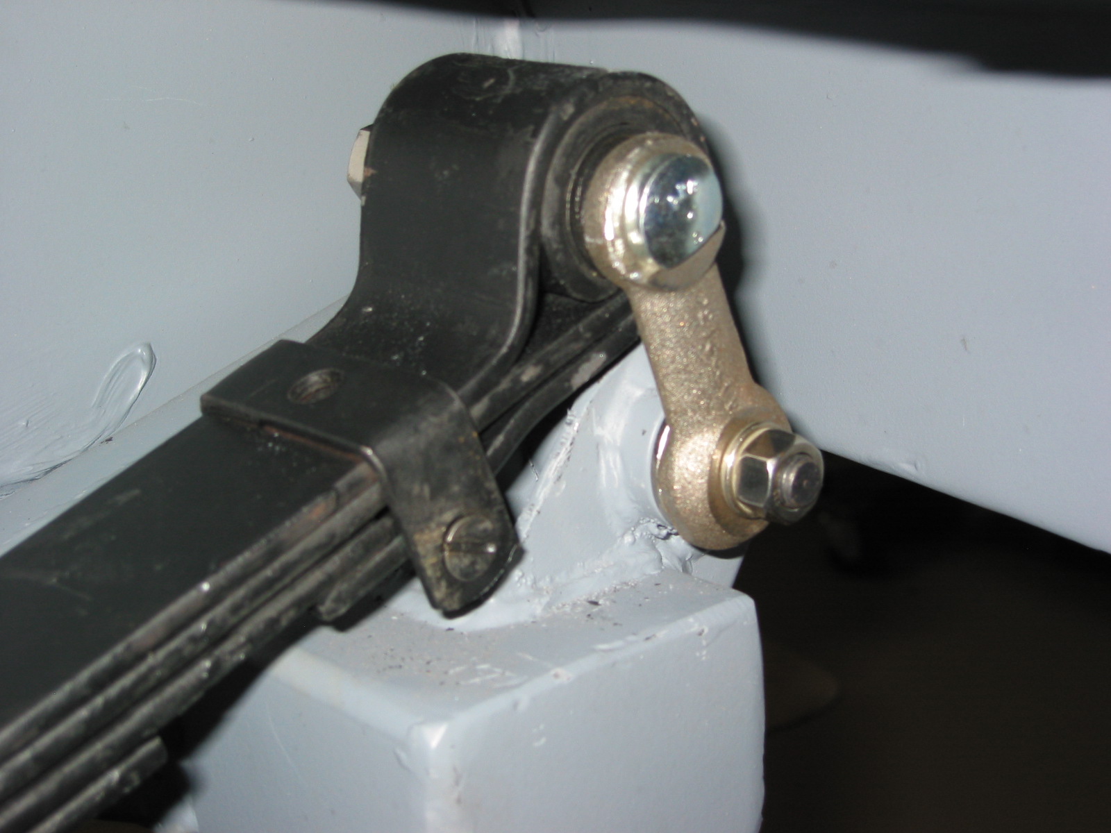
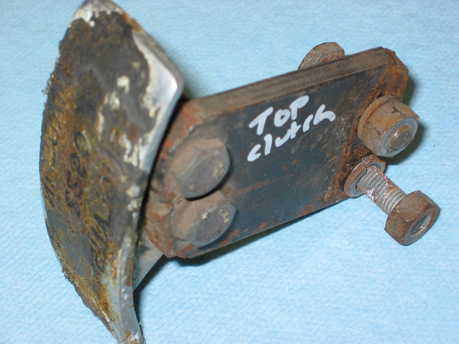
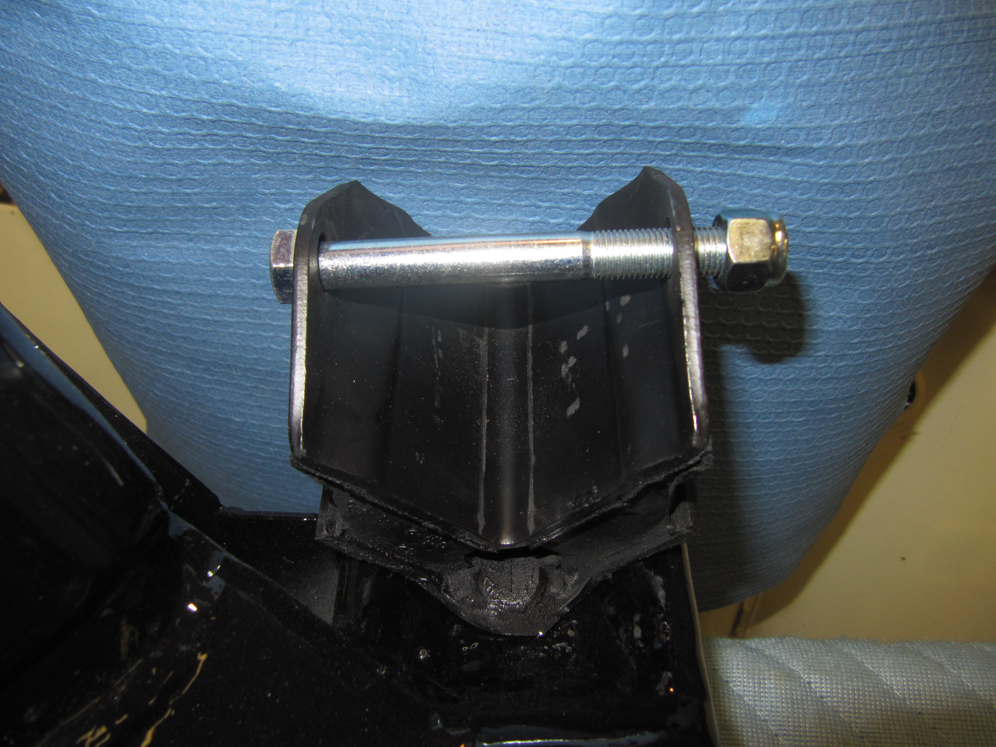
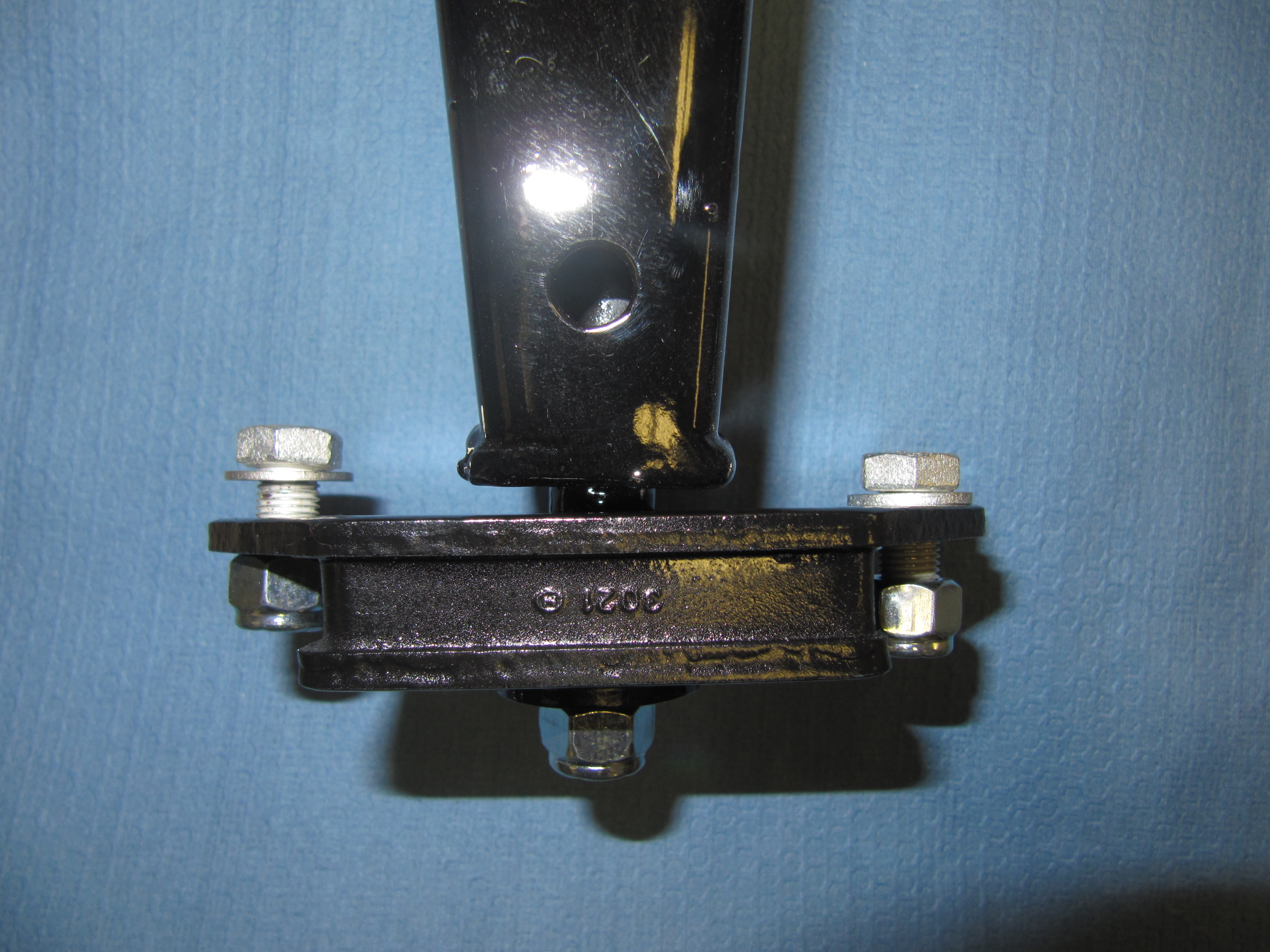
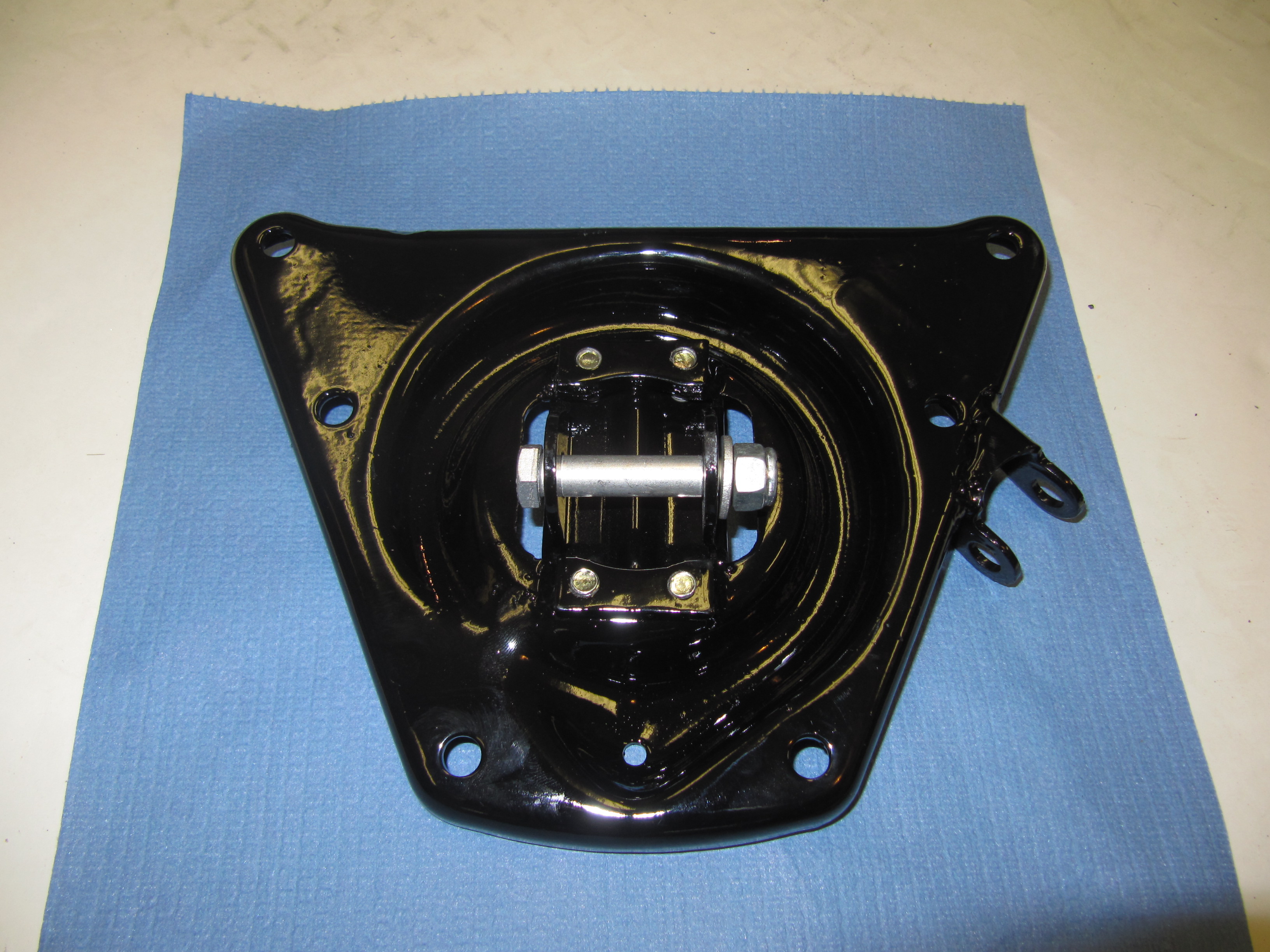
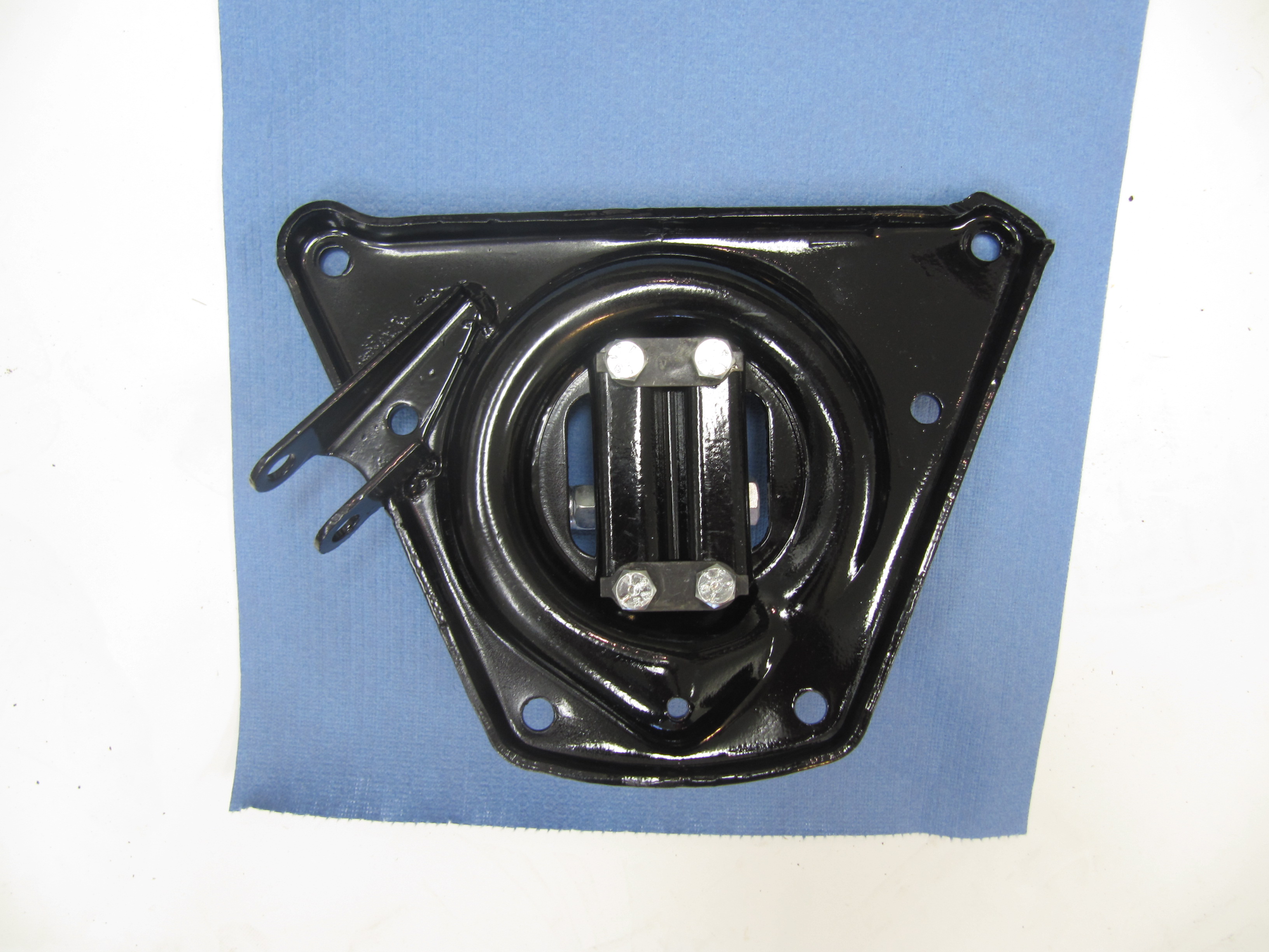
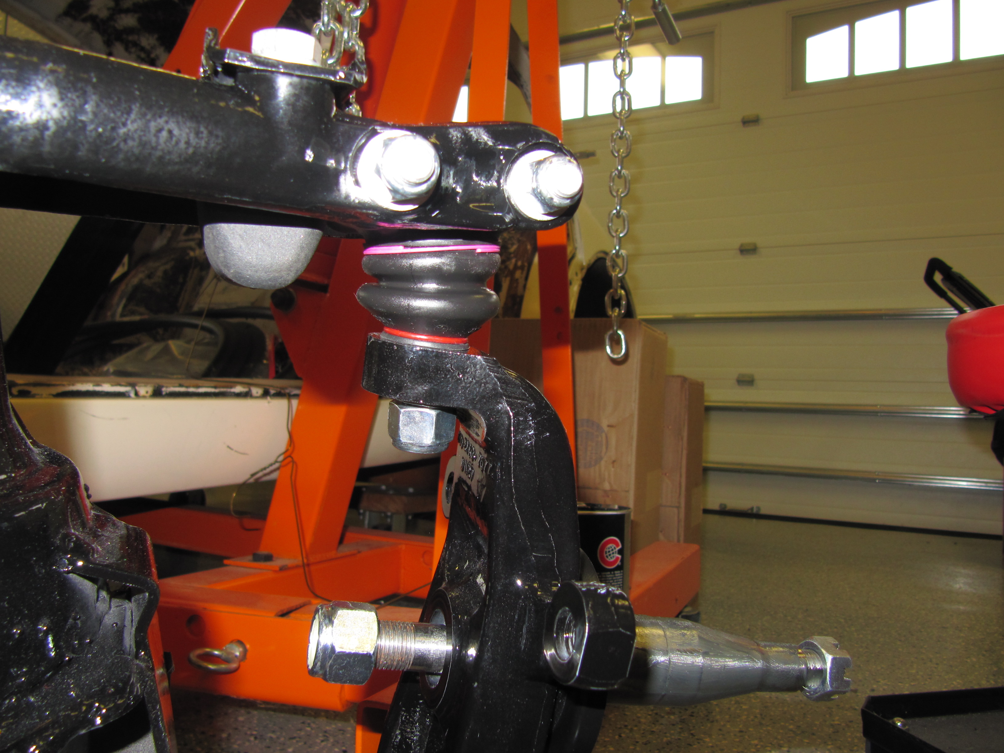
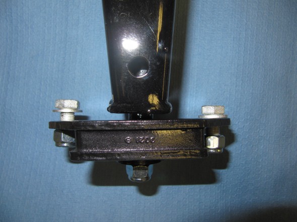
I was able to reuse many suspension pieces, but I did replace a few with new parts – particularly those with rubber, usually sourced from SNG Barratt. For example, I purchased new Rubber Mountings at Rear of Front Suspension Cross Member, otherwise known as “VEE” Brackets . I decided to “trial fit” these and all the other components (with the exception of the coil springs and shocks) of the front suspension so that when I become ready for the final installation everything will be prepared. This Bracket Mount requires two 3/8″ – 24 nylock nuts to secure the bonded studs of the mount to the cross member. A 3/8″ x 3 1/4″ – 24 bolt with a 3/8″ – 24 nylock nut is used to secure each of the “VEE” Bracket Mounts to the frame of the car.

“V” Mount
“V” Mount

“V” Bracket in Place
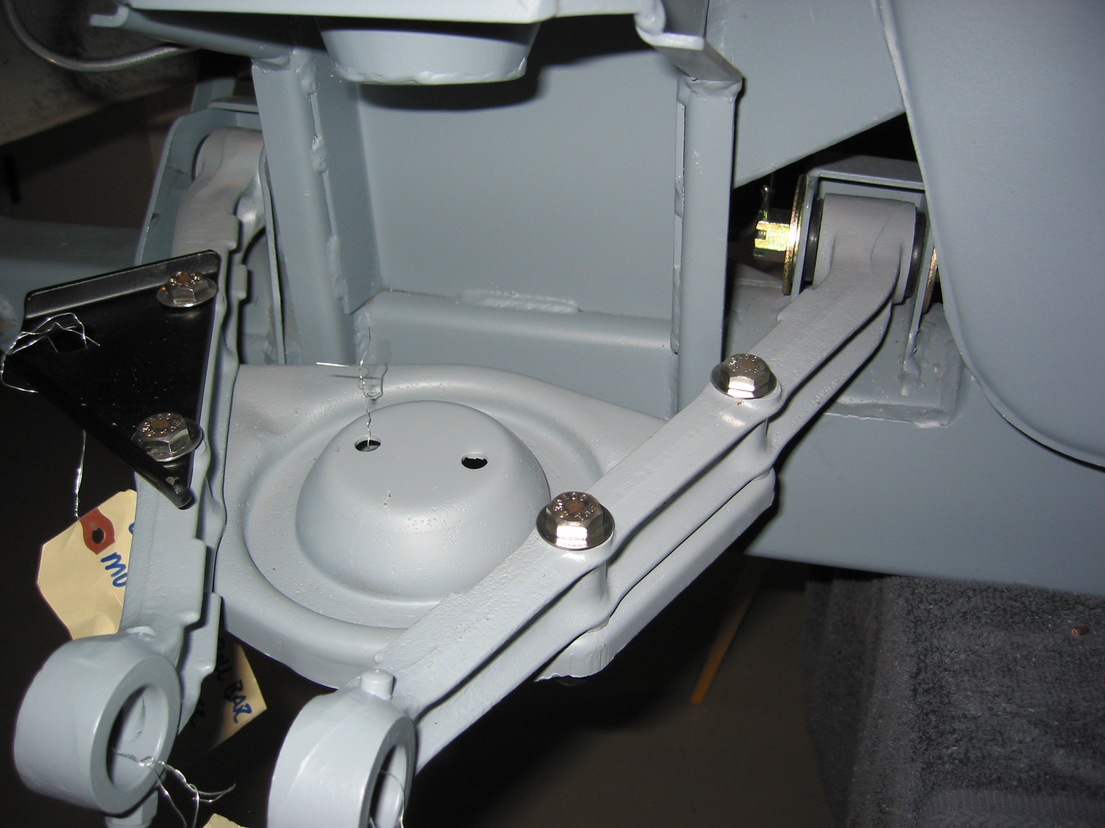
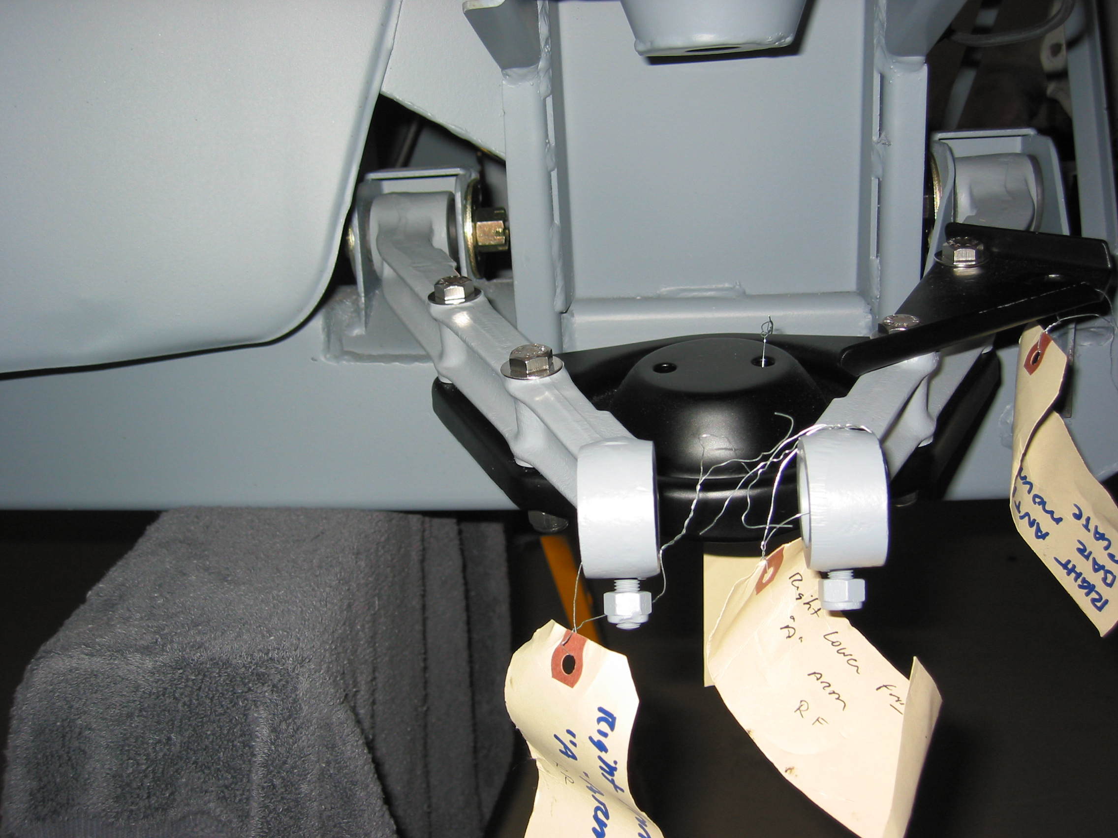
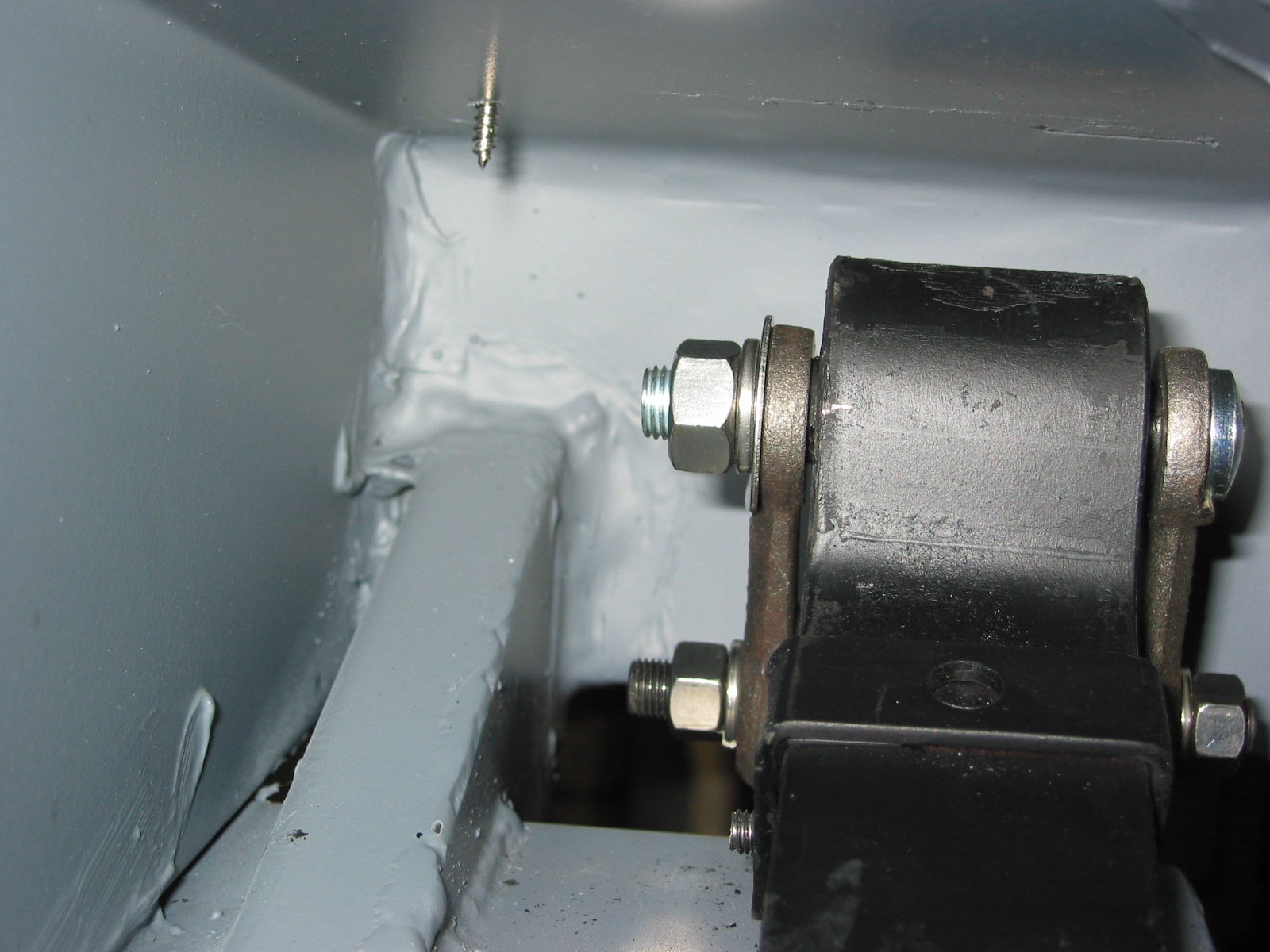
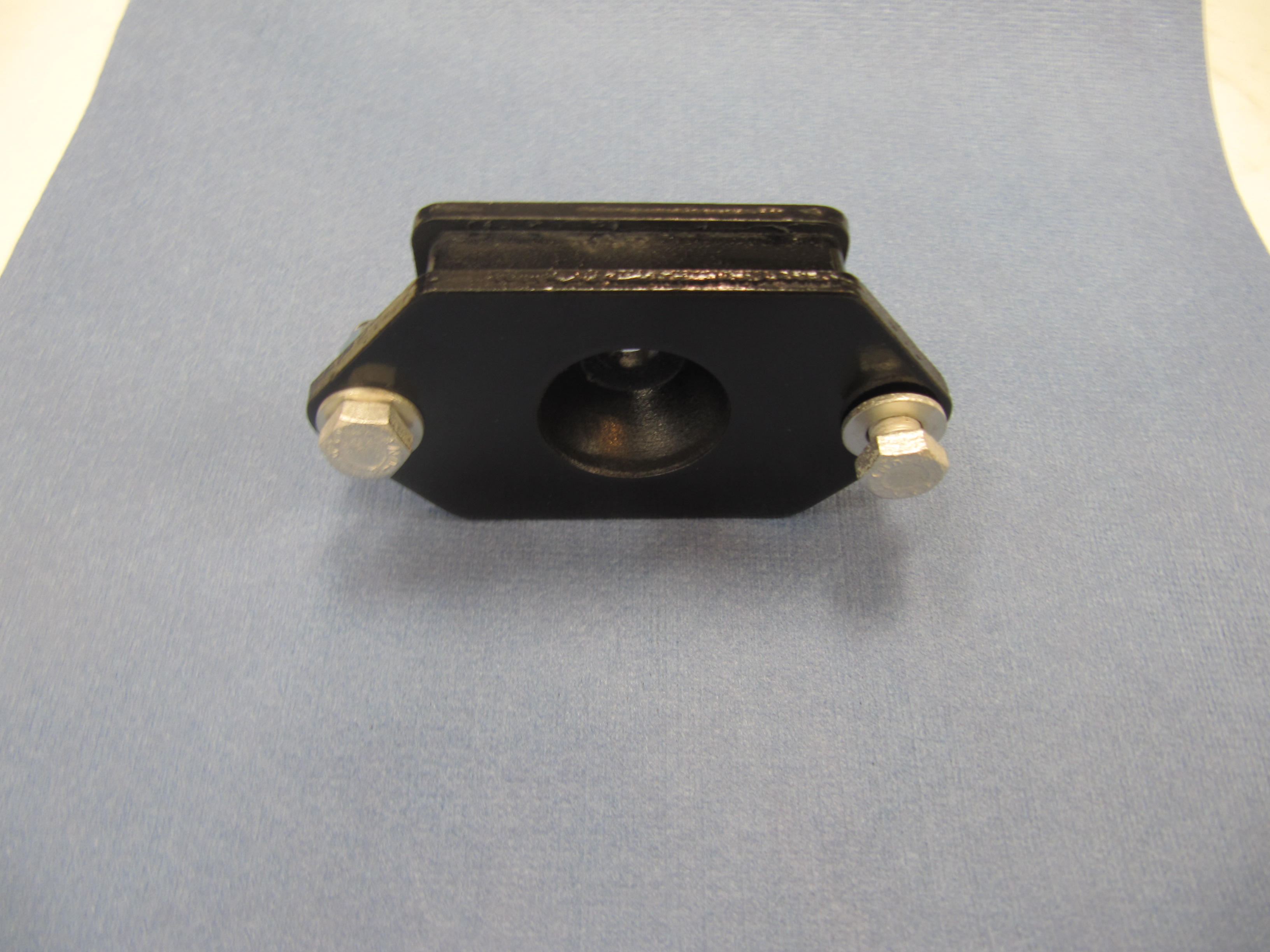
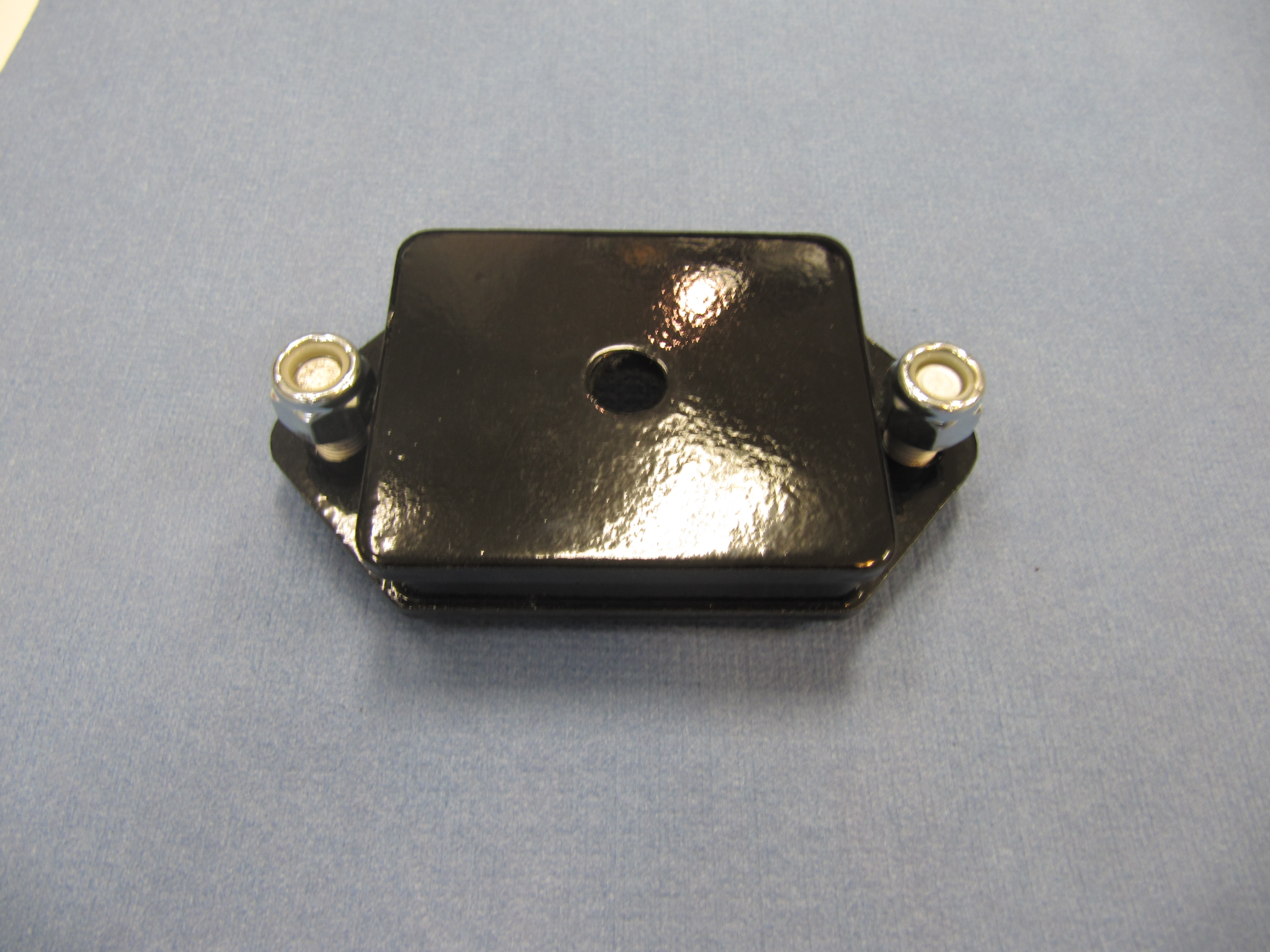
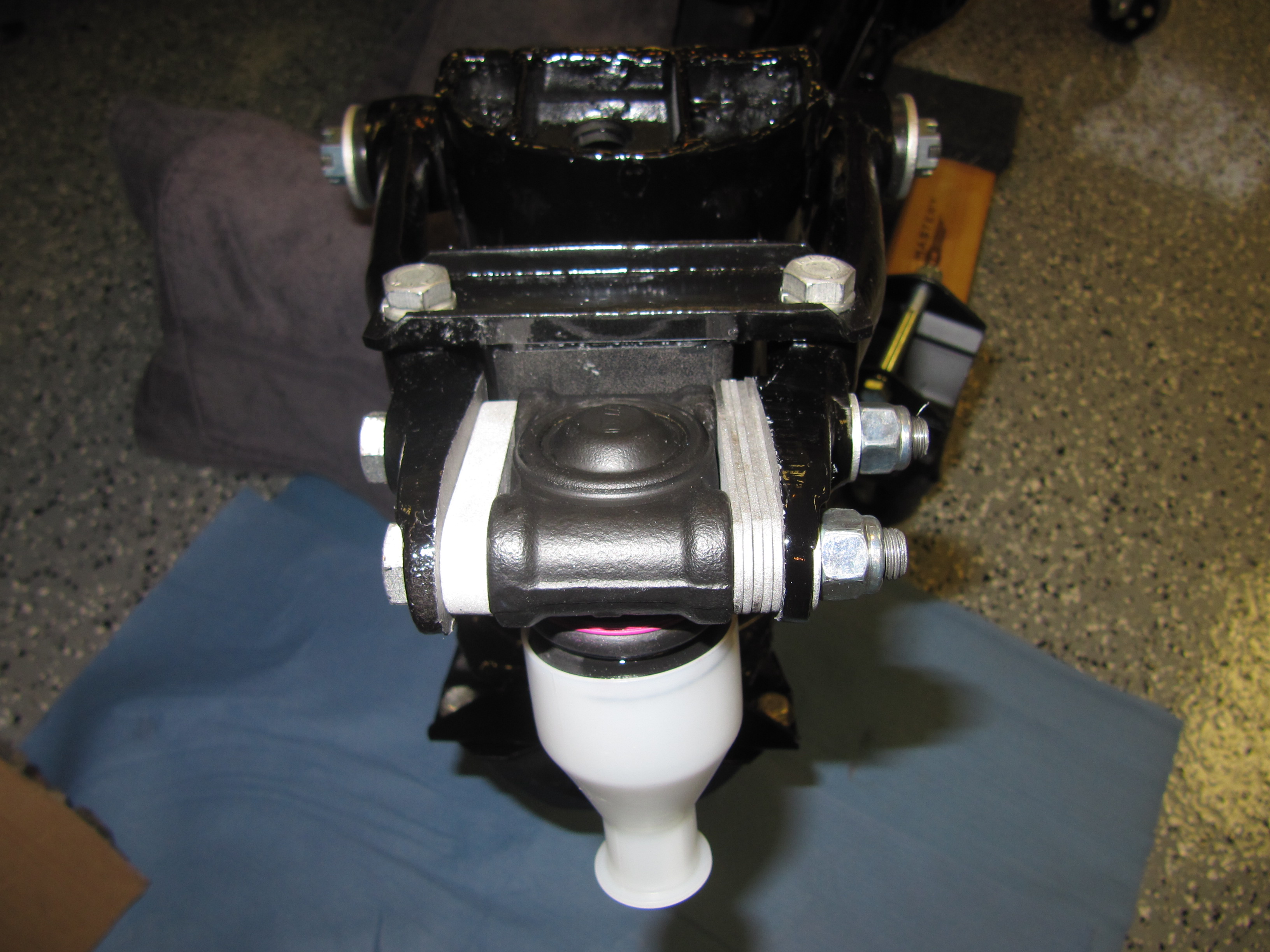
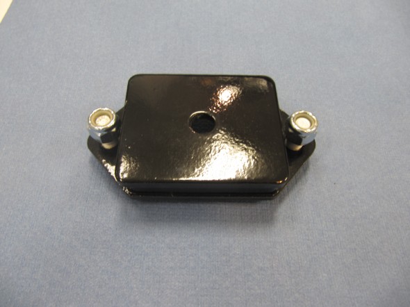
I also used new Rubber Mountings at Front of Suspension Cross Member. These are used to mount the front of the cross member to the frame. Each of these mounts use two 3/8″ x 7/8″ – 24 bolts with two flat washers and two 3/8″ nylock nuts. In addition the center fastener for each is a 7/16″ – 20 nylock nut with a special washer (thick) secured to the cross member stud.
Front Mount Installed
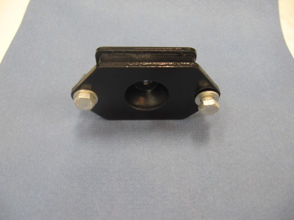
Front Mount
Front Mount

Front Mount Installed
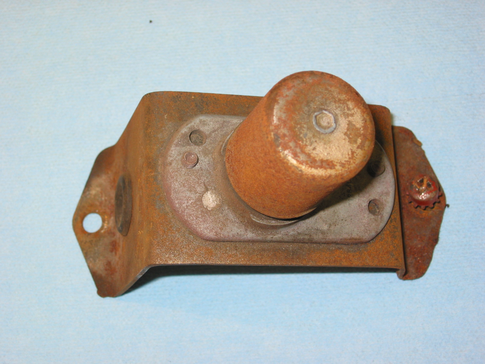
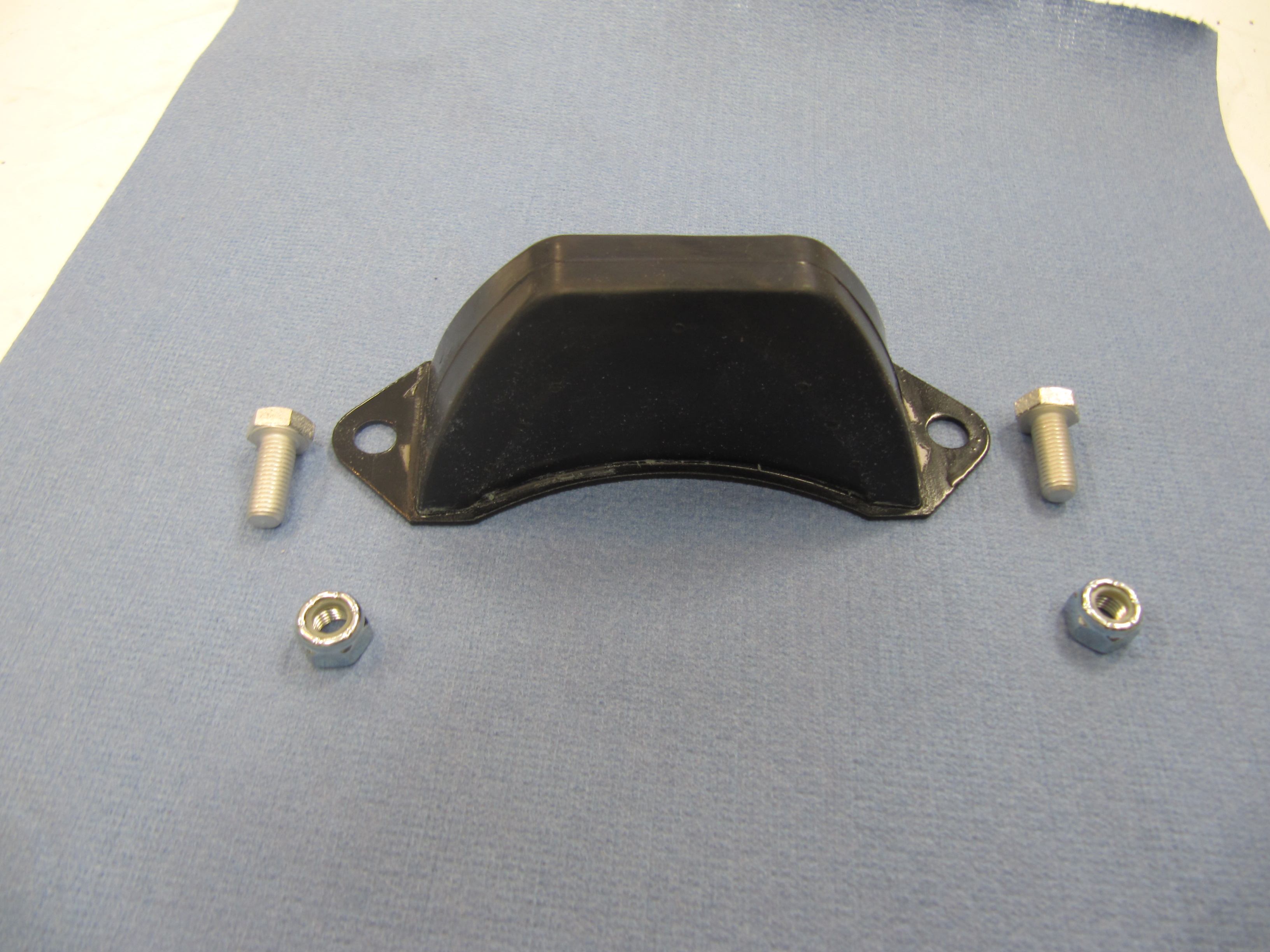
Bump Stops
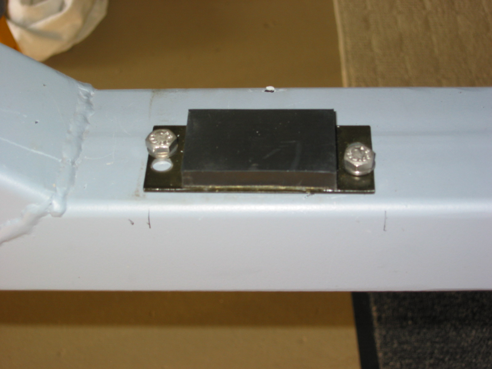
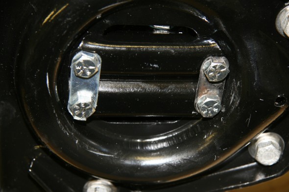
Another new rubber part located on either side of the cross member is The Bump Stop (Rubber) On Turret of Front Suspension Cross Member. Each Bump Stop is mounted to the turret with two 5/16″ x 3/4″ – 24 bolts and two 5/6″ – 24 nylock nuts. I added two stainless flat washers just to protect the paint on the turret.
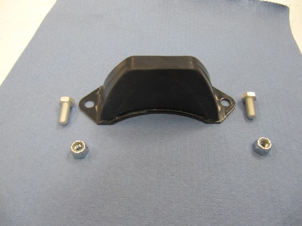
Turret Bump Stop
Bump Stop Installed
Front Shock Absorbers
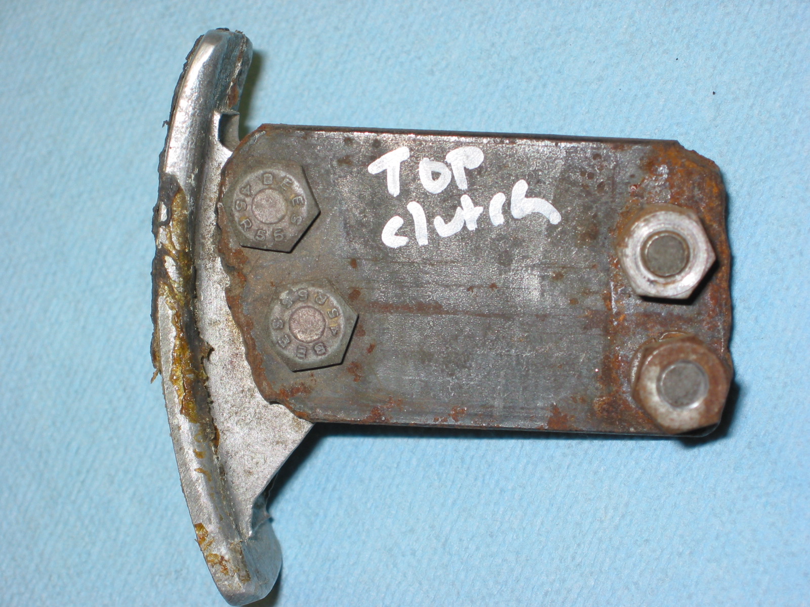
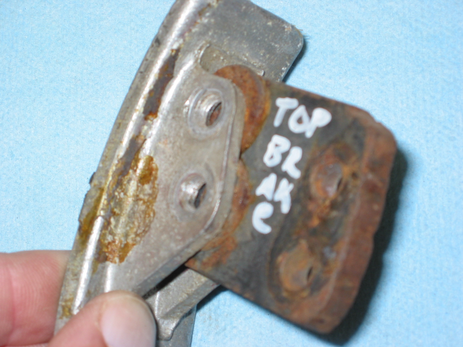
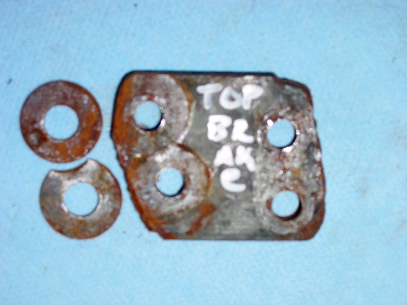
Each of the front shock absorbers is secured at the bottom with a Bracket, Under Spring Seat, For Mounting of Front Shock Absorber. The bracket is held in place to the Seat Assembly for Front Suspension Coil Spring by four set screws. The set screws are 5/16″ x 1″ – 24 (pointed). The set screws use tab washers to lock them in position. The front and rear tab washers are different lengths (slightly longer in the rear) and are available from SNG Barratt. A single 7/16″ x 2 5/16″ – 20 bolt with a flat washer and a 7/16″ – 20 nylock nut holds the shock absorber to the bracket.

Front Shock Absorber Bracket

Bracket in Spring Seat

Bracket in Spring Seat
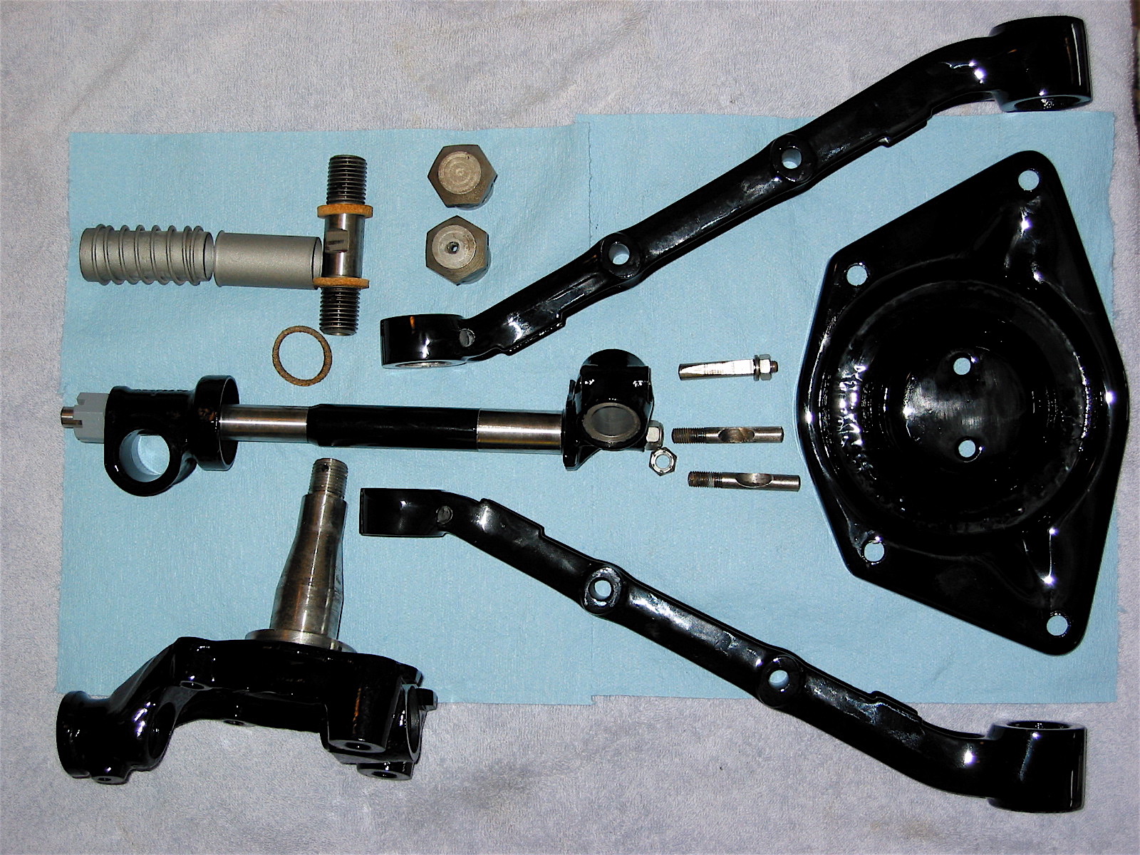
The Upper Wishbone Assembly
The Upper Wishbone Assembly is comprised of the LH and RH Levers, the Fulcrum Shaft, the Ball Joint Assembly for Upper Wishbone, and the Rebound Stop (Rubber) on Upper Wishbone Levers. To assemble these components one would first install the LH and RH Fulcrum Shafts to the turrets of the cross member, and then attach each Lever. However, to illustrate the components in the photographs I have assembled them detached from the turret.
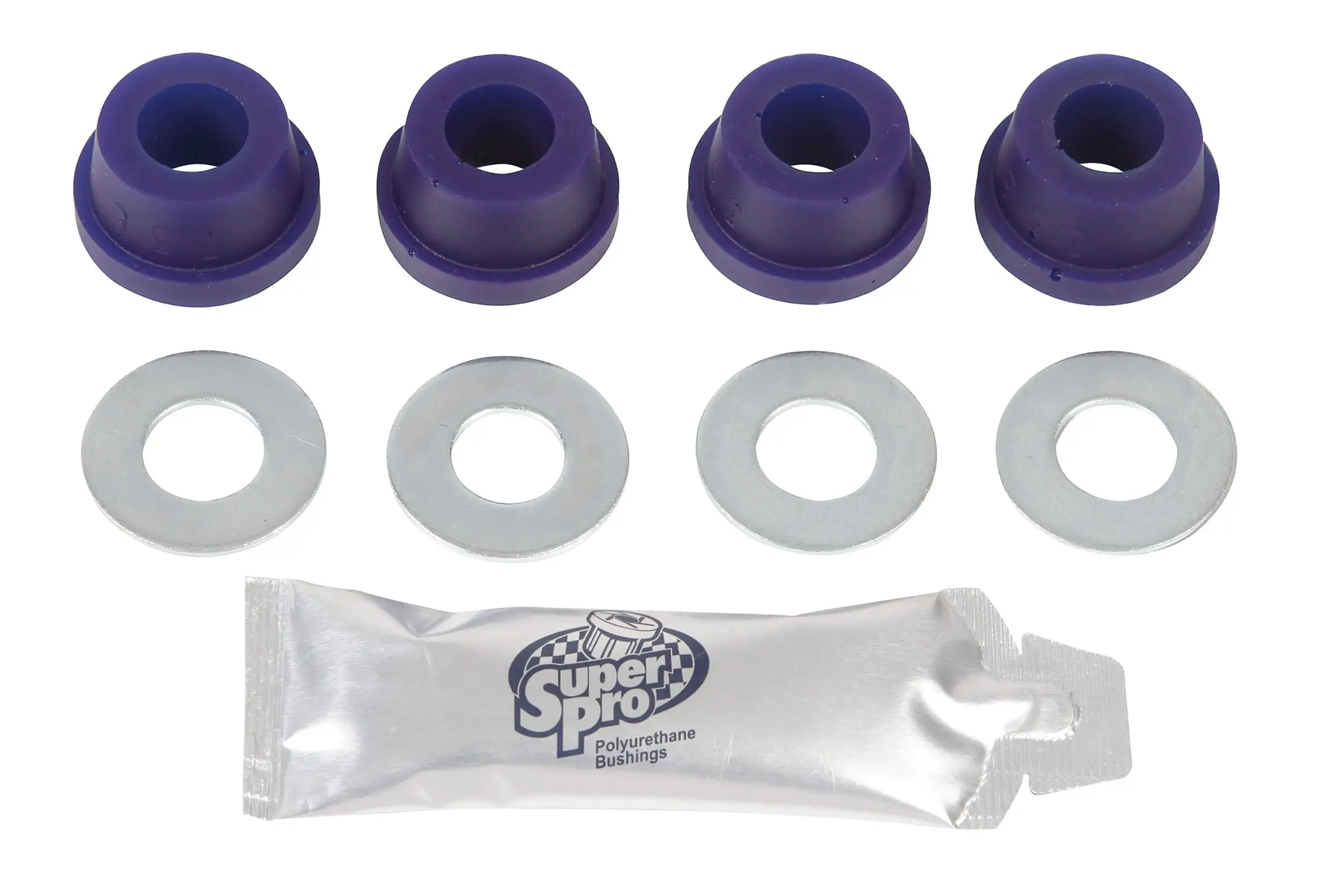
The first step was to press the bushings into the lever ends. I am using Polybushes rather than the original metalastic rubber bushings.

Polybush Front Kit
I suppose that there are various means to insert the bushes into the levers. I simply used a vice with properly sized socket that permitted the bush end to slide into the socket as the vice pushed the bushing home. To make the process simpler I used a liberally applied poly grease from Prothane. The Prothane Grease is not a “grease” as we commonly know it. It is actually very sticky stuff! I used it with success in my Austin-Healey restoration. Polybush recommends using dishwashing soap to lubricate the bush, but I didn’t want to deal with the soap residue.

Inserting the Polybush
I then placed each Lever on the Fulcrum Shaft. A 1/2″ cupped Distance Washer is placed on each end to the Fulcrum Shaft first, with the cup facing the center of the Shaft. The Lever is then slid on to the Fulcrum Shaft, followed by a 1/2″ Special Washer (thick), then a 1/2″ – 20 Slotted Nut and a Split Pin to retain the Nut.

Levers To Fulcrum Shaft
Each Rebound Stop (Rubber) On Upper Wishbone Levers is secured to the Levers with two 3/8″ x 3/4″ – 24 set screws and 3/8″ spring washers.

Rebound Stop

Upper Wishbone Assembly
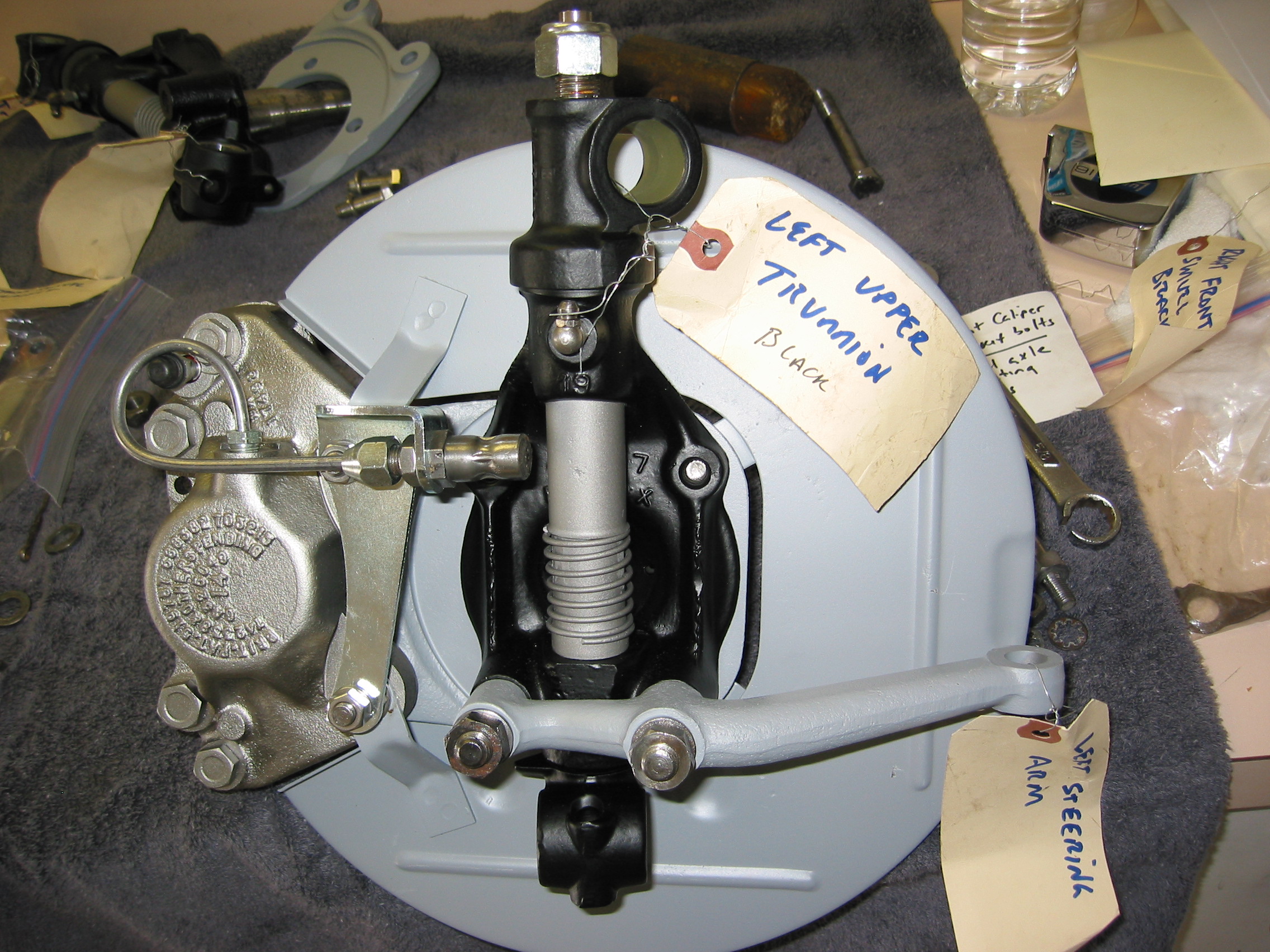
Ball Joint Assembly For Upper Wishbone Levers
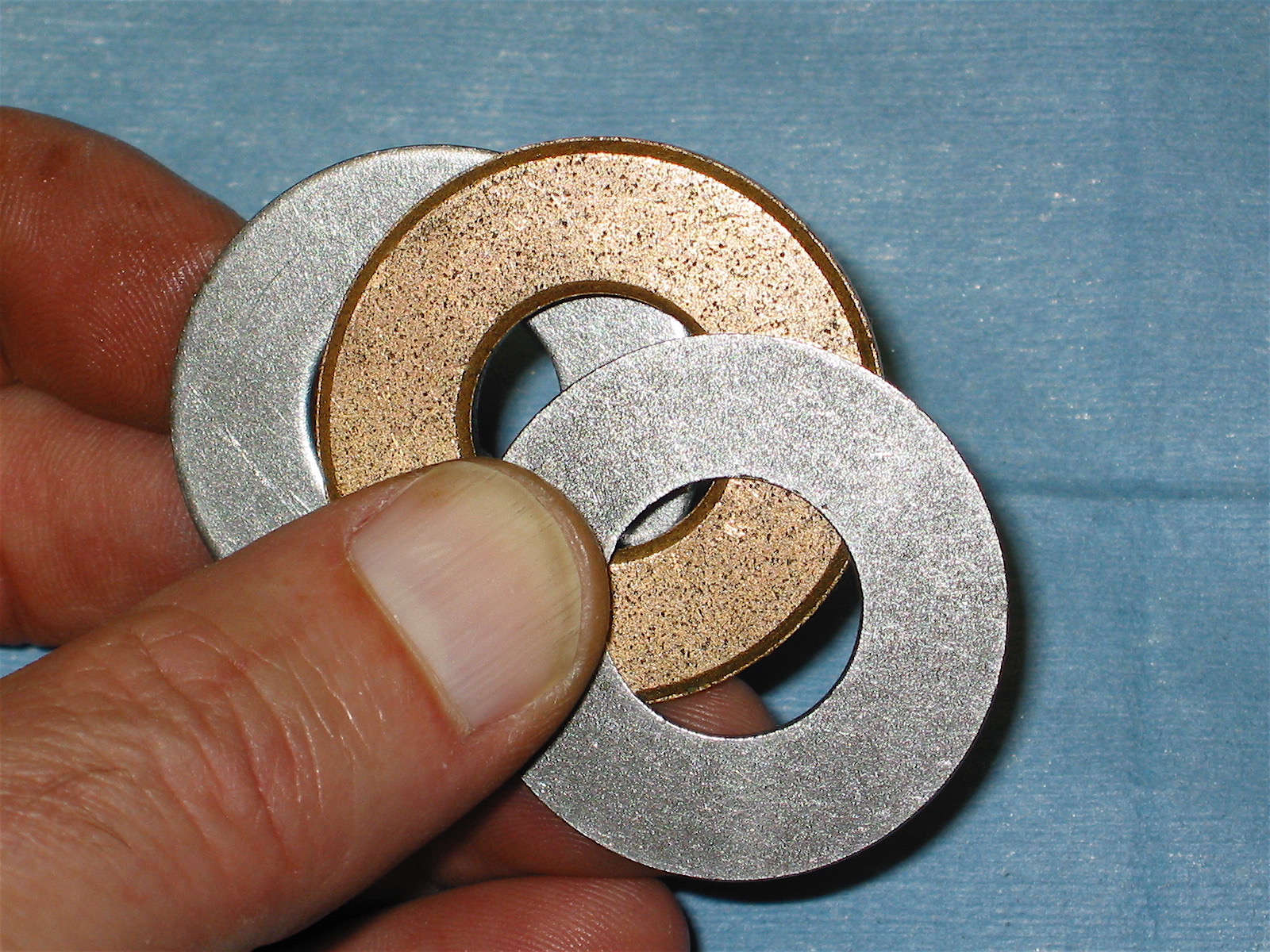
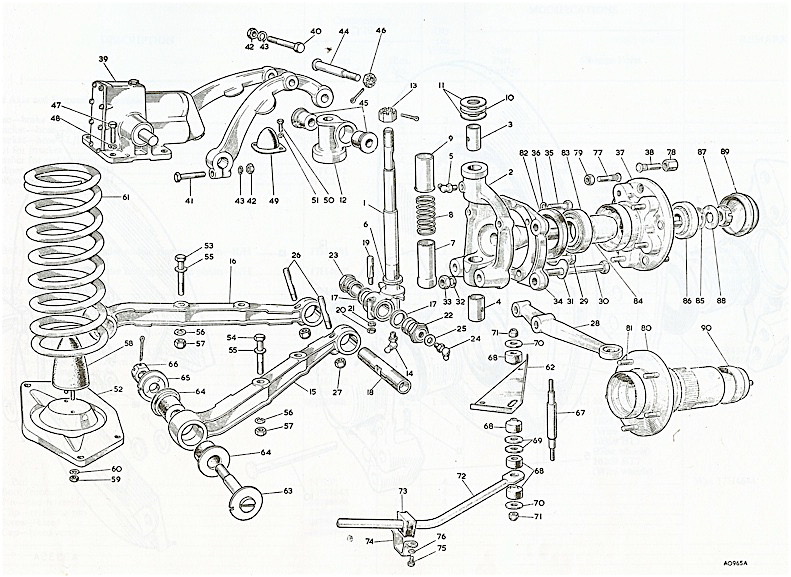
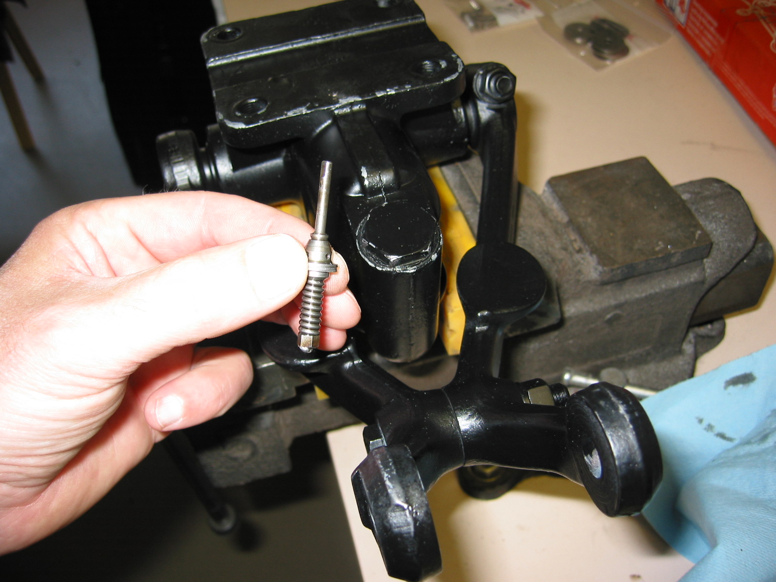
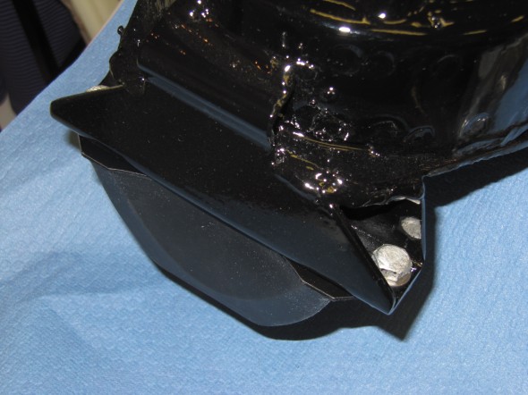
The original ball joints required greasing as part of routine maintenance. A grease nipple was located on the top of each ball joint. Today, modern sealed units are available as replacements and I decided to substitute these in my restoration. The image below shows the Upper Ball Joint, the shims that are used to adjust the castor angle, and the Distance Piece. As a starting point for proper front end alignment, I will rebuild the front suspension with the same shims as were in place when I disassembled the car.

Upper Ball Joint Assembly with Spacer and Castor Shims
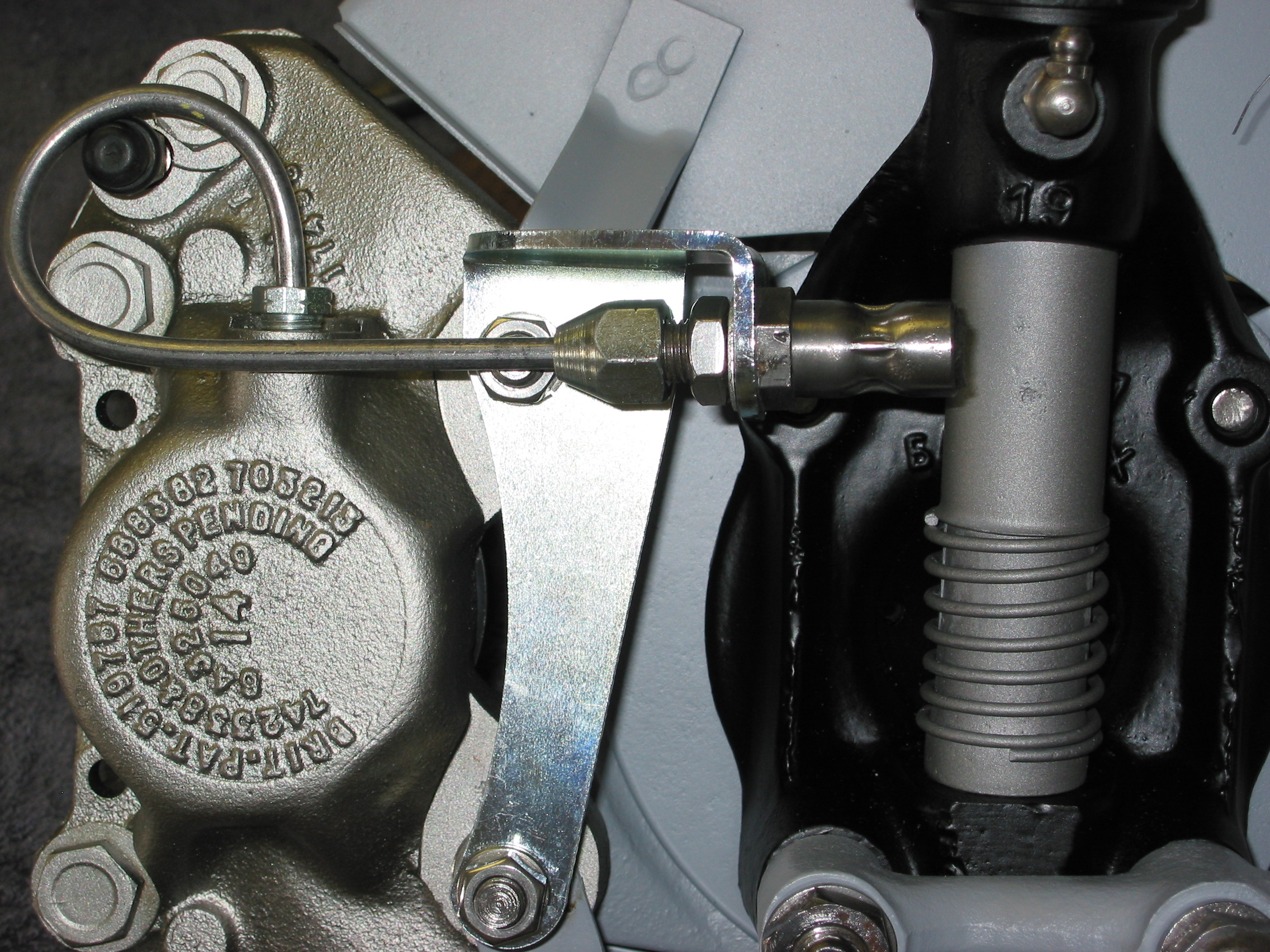
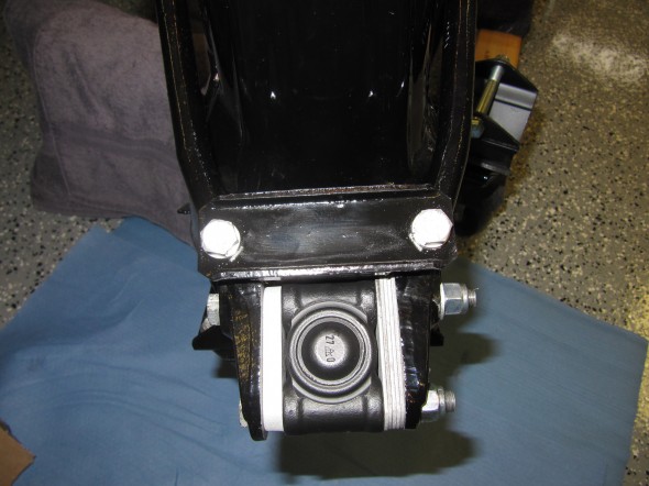
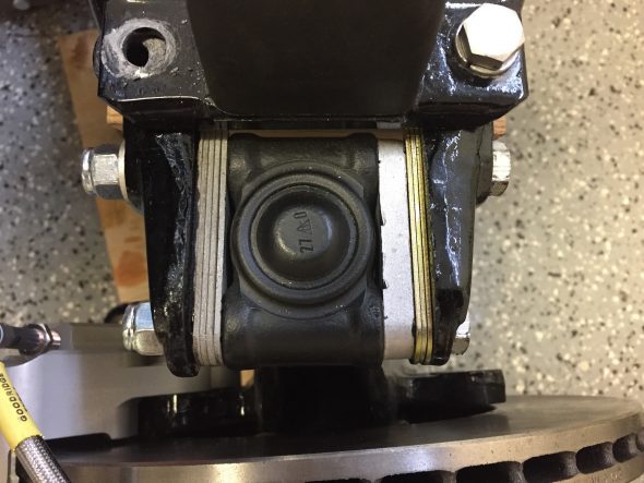
The following images show the LH Upper Ball Joint installed. The Ball Joint is fastened to the levers with a longer 3/8″ x 4 3/8″ – 24 bolt to the inside and a shorter 3/8″ x 3 1/4″ – 24 bolt to the outside. 3/8″ flat washers and 3/8″ – 24 nylock nuts secure the Ball Joint. A 9/16″ -18 nylock nut is used to fasten the ball joint to the Stub Axle Carrier. On both sides of the car, the distance piece is fitted to the front of the car, with the shims to the rear. The bolt heads and washers are similarly to the front and the nylock nuts to the rear.
LH Ball Joint Shims

LH Ball Joint Shims
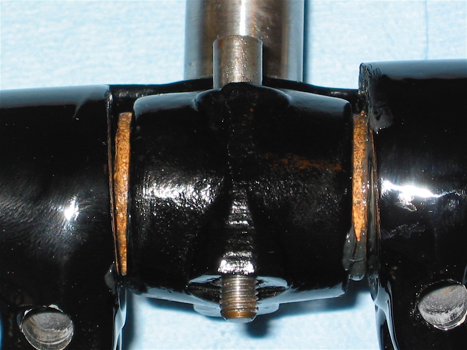
After having mounted the castor shims as they were removed from the car I discovered that Jaguar Mark 2 Models Service Manual states that “A packing piece and 8 shims must be always fitted between the wishbone levers and the upper ball joint; their relative positions may, of course, not always be the same.”
The manual also has an image: Figure 15 shown below. This image clearly shows five 1/16″ shims to the left of the ball joint and three 1/16″ shims to the right accompanied by the wider aluminum packing piece.
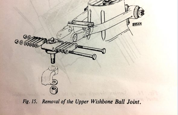
Castor Shim Diagram
So… I tried what the manual indicated:
Eight Castor Shims Installed
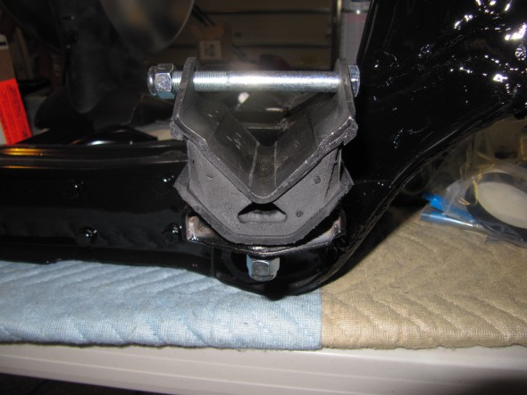
Once this is done it is impossible to mount the rubber bump stop and its bracket to the mounting holes in the wishbones. The holes for the bolts will not align as the wishbones have been separated too far by the 8 shims plus the packing piece! See the photo below and notice how far off the alignment is. By the way, I know the rubber bump stop is upside down. I consulted with a few friends who are restoring MK2s and with the various Jaguar MK2 forums and the general consensus is that the Service Manual is in error. From what I have been able to ascertain, eight shims were used on the earlier cars that had pressed steel wishbone levers, but when Jaguar moved to forged levers it also used the spacer and five 1/16″ shims instead of eight! In the figure above someone actually revised the levers to depict forged items, but they forgot to change the number of shims.
Bottom Line – back to the spacer block and five 1/16″ shims as was the case when I removed the shims from the car upon disassembly.
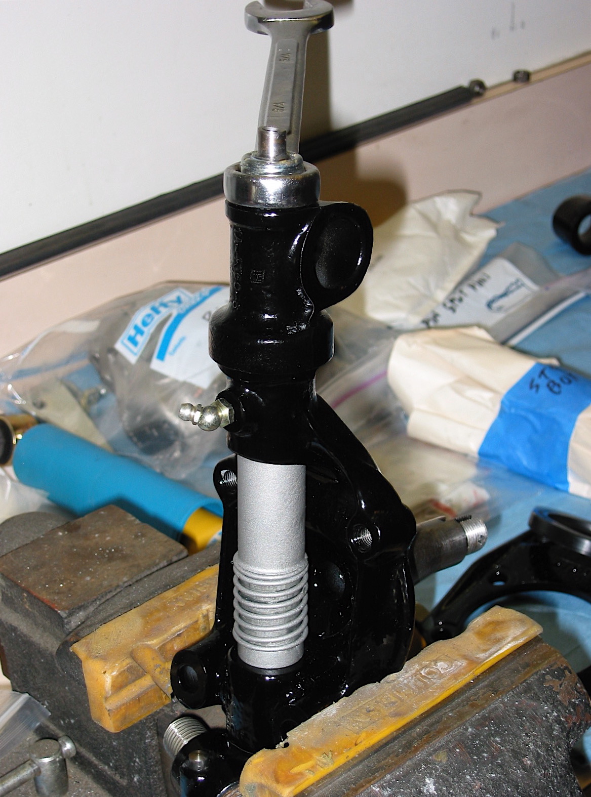
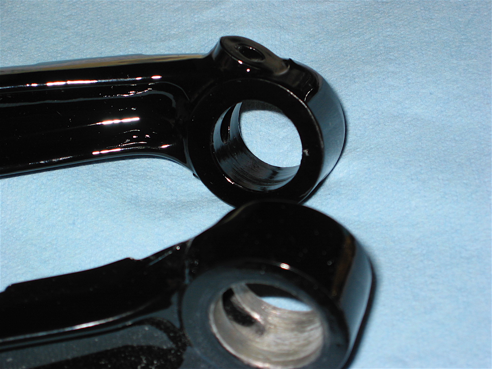
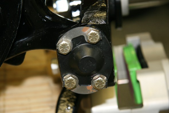
Fulcrum Shaft, for Mounting of Upper wishbone Levers
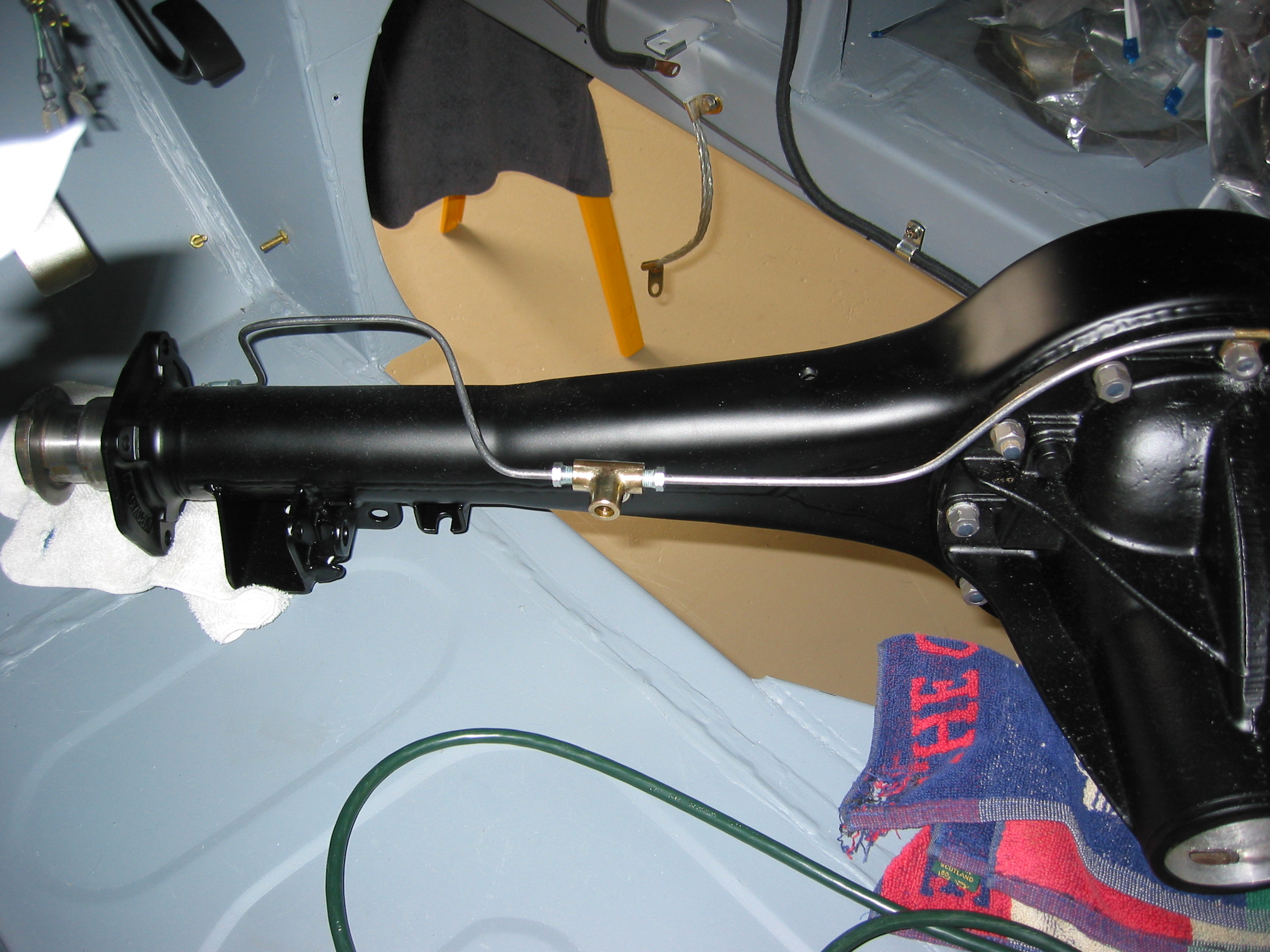
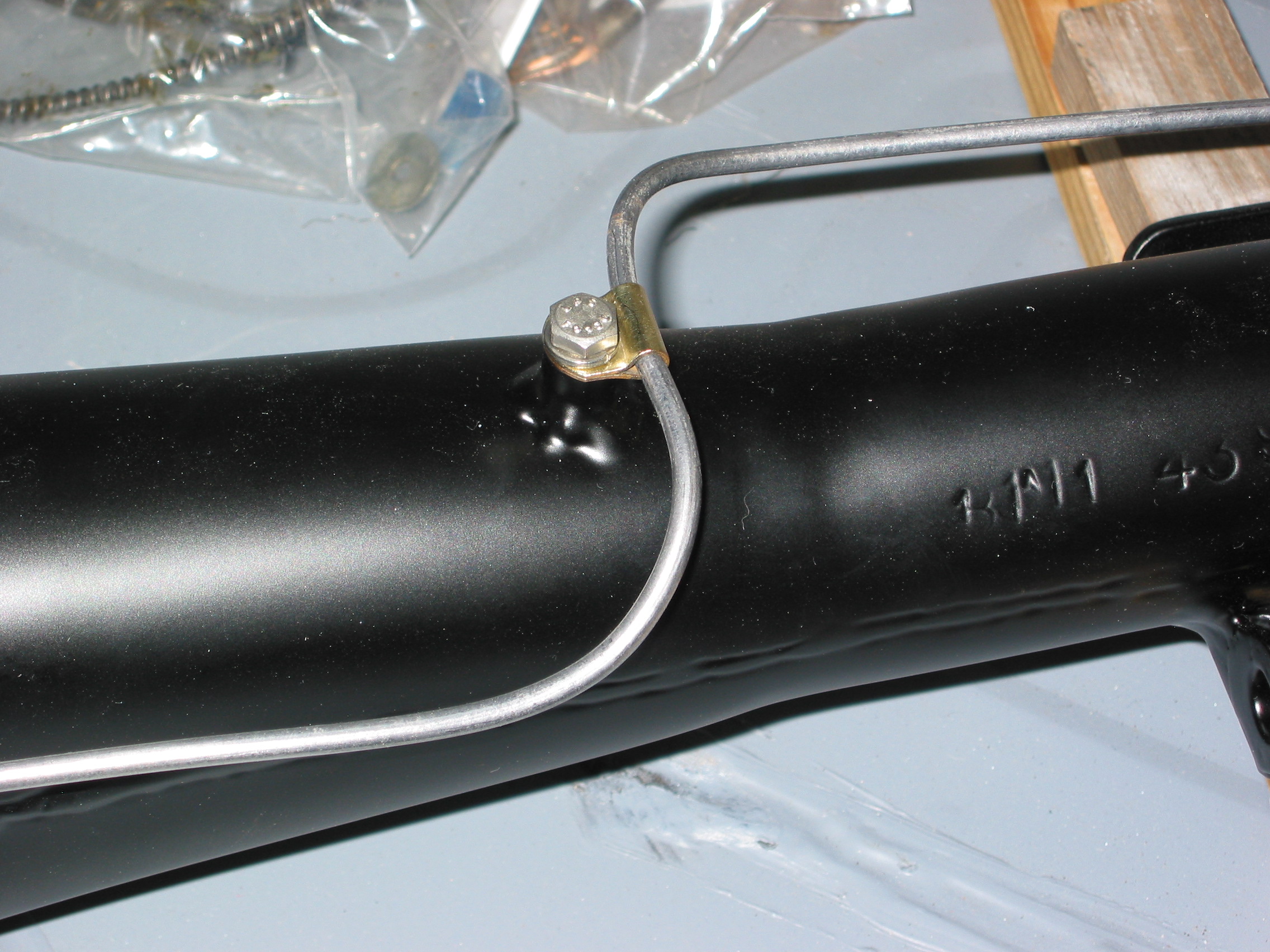
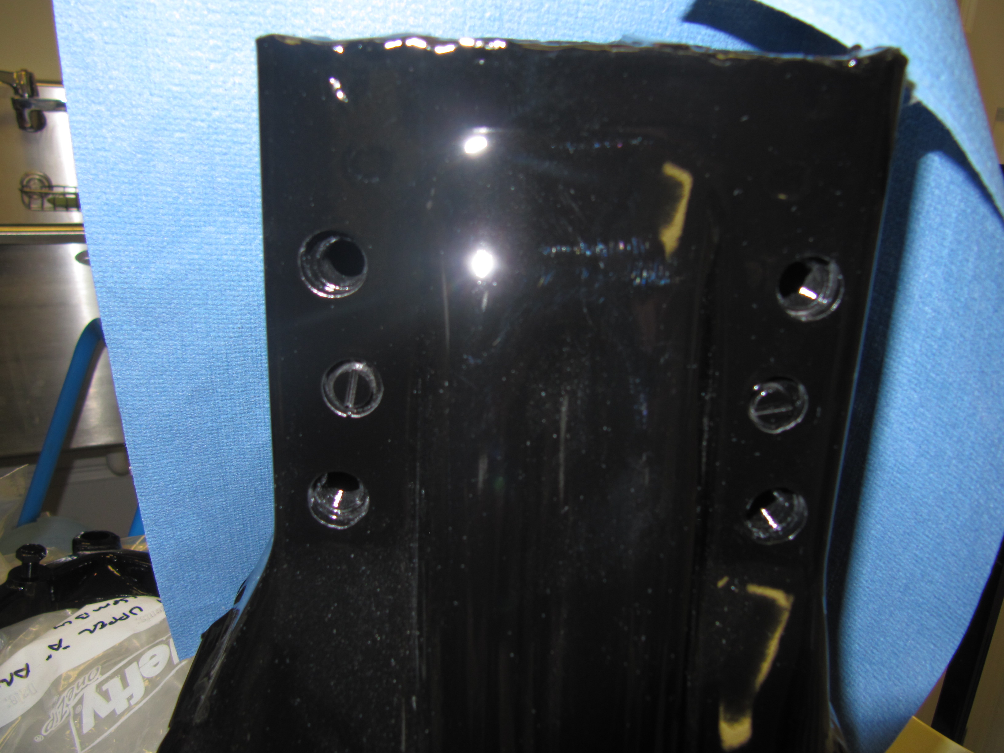
I then disassembled the upper wishbone assembly to mount the LH Fulcrum Shaft to the cross member turret. The Fulcrum Shaft is attached to the turret with four bolts and spring washers. The upper bolts are 3/8″ x 2 1/2″ – 24 (pointed) and the lower bolts are 3/8″ x 1 5/8″ -24 (pointed). These bolts screw into threaded plates inside the turret, as can be seen in the image below. Camber Shims seat between the fulcrum shaft and the turret. As with the Castor Shims, I am replacing the shims as they were removed. Adjustments will be made later and as needed when the car is aligned. Therear moiunt

LH Upper Fulcrum Shaft with Camber Shims and Bolts

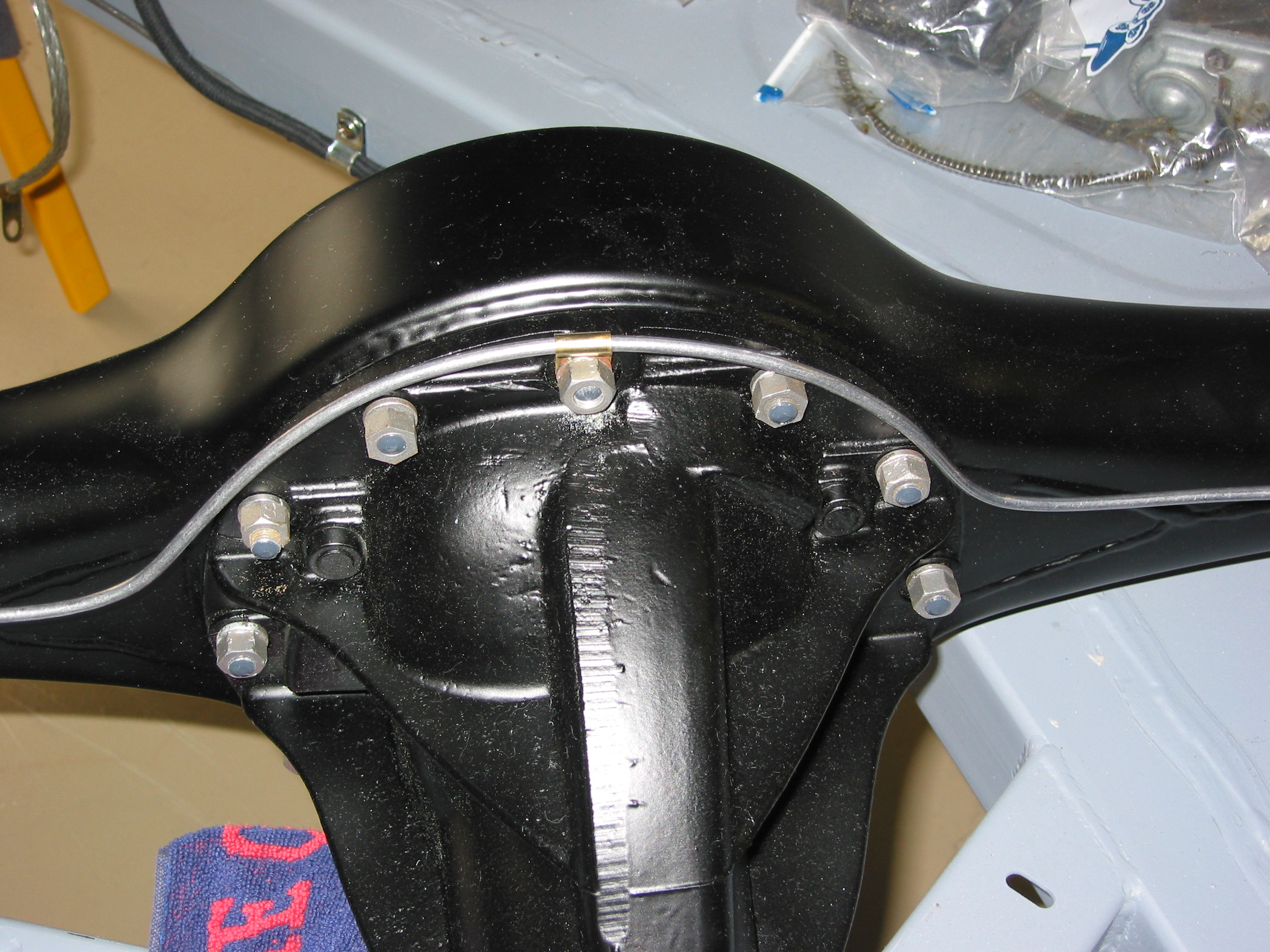
Cross Member Turret

Fulcrum Shaft Installed
I then put anti-sieze on the shaft ends and reinstalled the levers on the fulcrum. Working from the center of the shaft, one first places the distance washer, followed by the lever, the special washer and a 1/2″ – 20 slotted nut and split pin. The slotted nuts are not to be tightened with split pins inserted until the car is on the ground and the full weight of the vehicle is on the suspension.
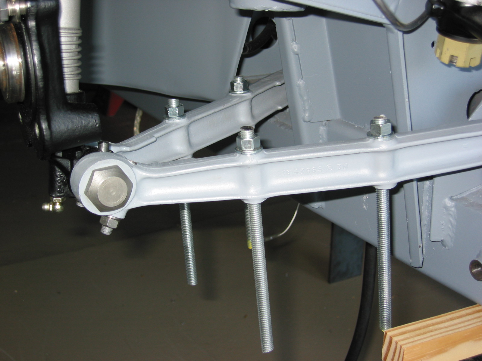
Lower Wishbone Levers
With the upper wishbone assembly complete, I next moved to the Lower Wishbone Assembly. First, I installed the polybushes for the lower wishbone levers just as I had with the upper levers.
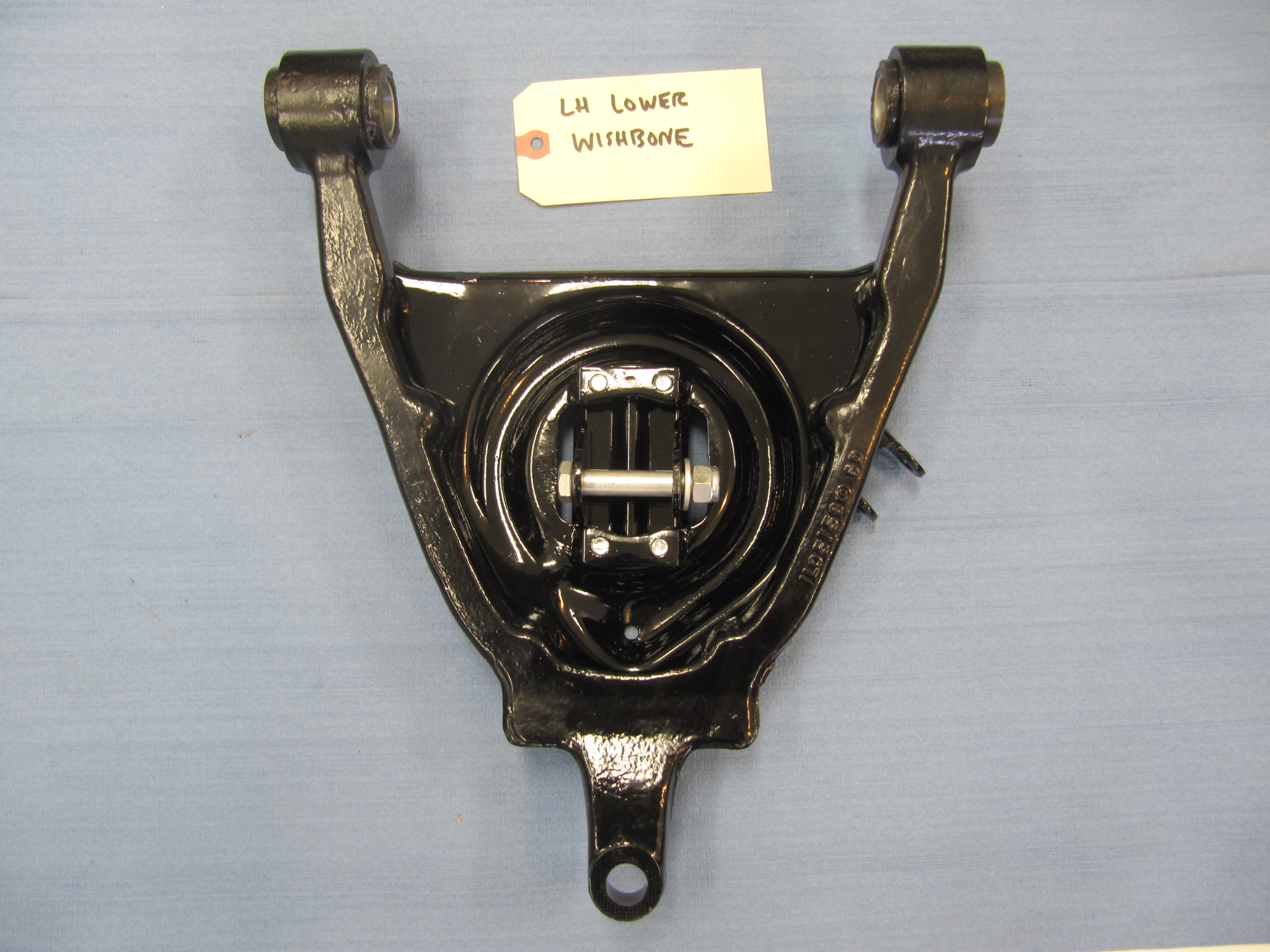
While final assembly with the coils springs and shock absorbers will be completed later, for purposes of this summary, I attached The Seat Assembly for Front Suspension Coil Spring to the Lower Wishbone Lever. Unlike the upper wishbone, the lower wishbone is one piece. Each seat assembly is fastened to the lower wishbone with five 3/8″ x 1″ – 24 bolts (pointed) and one 3/8″ x 1 1/8″ – 24 bolt (pointed). Each bolt has a thin wall spring washer. I also added thin stainless flat washers under the spring washers just to protect the new paint.

Lower Wishbone
Wishbone & Spring Seat
Wishbone & Spring Seat
Fulcrum Shaft For Mounting of Lower Wishbone Levers to Front suspension Cross Member
I ordered new lower fulcrum shafts. These proved to be quite tight in the polybushes I had planned to use in the lower wishbone. I put the shafts in the freezer hoping that might help and I liberally coated the bushes and the crossmember with anti-sieze, but the fit remained too tight. I eventually gave up on the polybushes and installed the standard rubber bushes. These worked fine.
After positioning the lower wishbone, I tapped the shaft through the wishbone bushings and the crossmember and then fit the thick special washers on each end of the shaft with 9/16″ – 18 slotted nuts and a split pin.
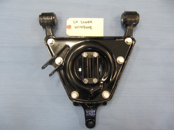
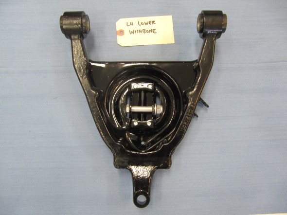
OOPS! The two photos below shows the RH Lower Wishbone, but by mistake I installed the LH Spring Seat in the wishbone. I discovered it later (January 28, 2012) when I started to install the anti-roll bar and saw that the mounting bracket was to the front of the car, rather than the rear. Sorry – all is now properly configured!

RH Lower Wishbone with Bushings

RH Lower Wishbone Installed with Lower Fulcrum Shaft
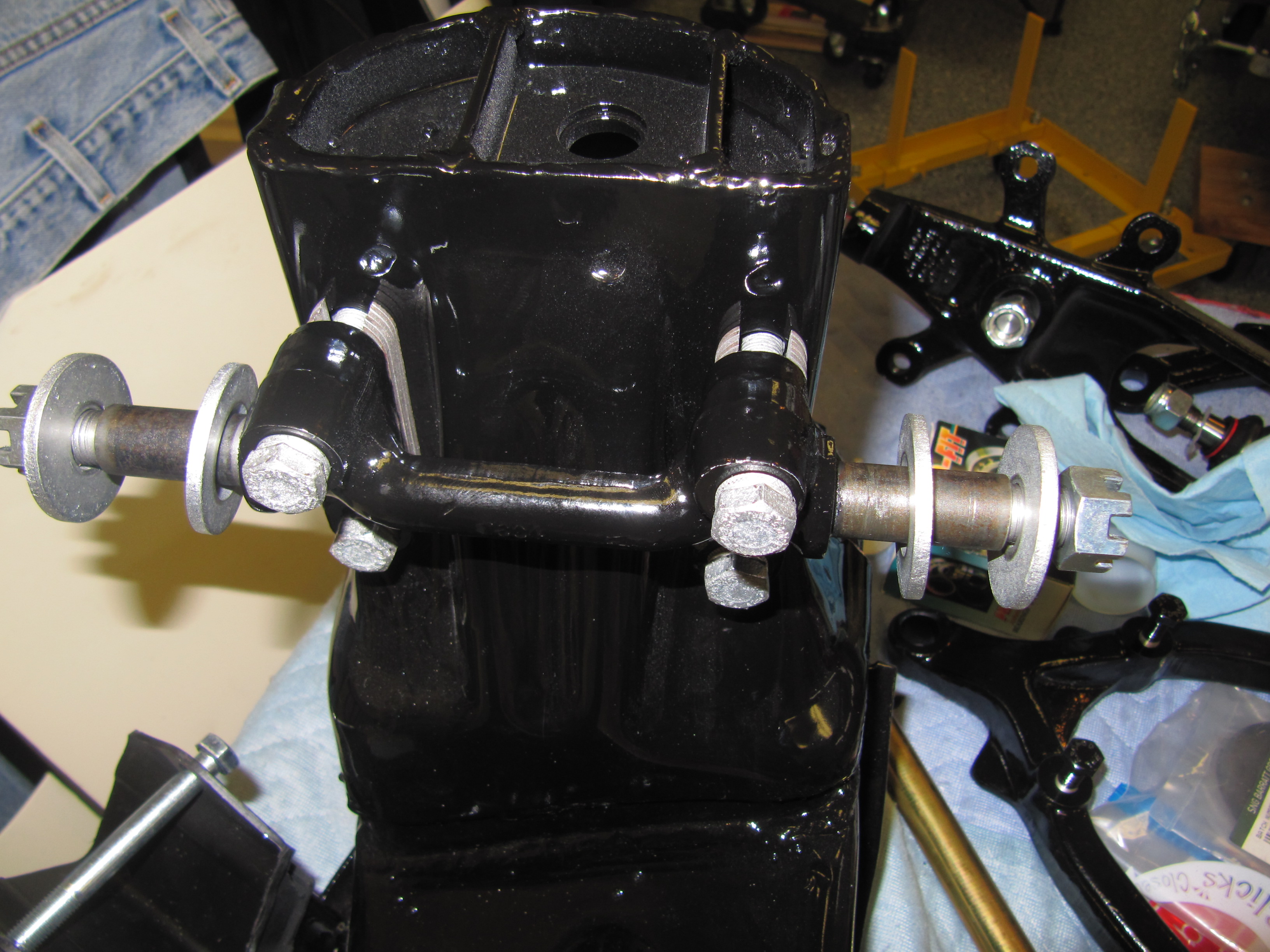
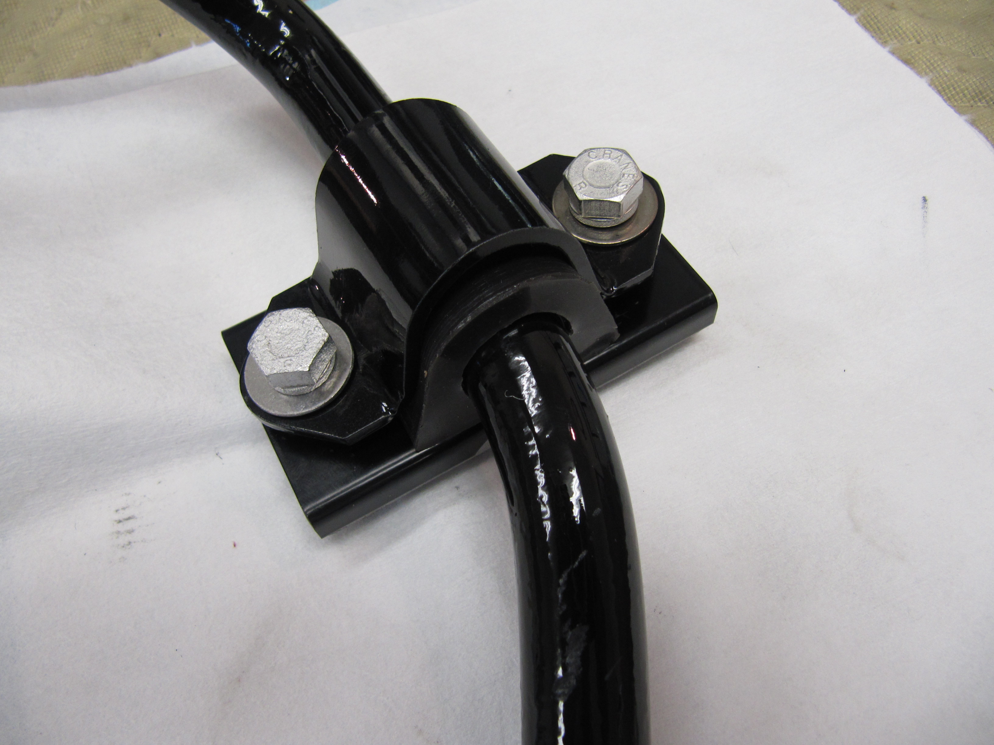
Anti-Roll Bar
The Anti-Roll Bar is secured to the chassis side members with two support brackets that house rubber (or in my case, poly) bushings. These bushings are cut so that they can be “opened” and placed around the bar. Two 3/8″ x 1 5/8″ – 24 bolts with spring washers go through each of the brackets, a keeper plate, and an aluminum packing block before screwing into the chassis side member. This is depicted in the Plate 62 above as parts #73-76. The nylock nuts in the image below are not part of the required hardware, they are simply holding the components together until the anti-roll bar is mounted to the car. Again, I have added non-original stainless flat washers under the spring washers to protect the paint on the support brackets.
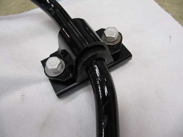
Anti Roll Bar Frame Mount
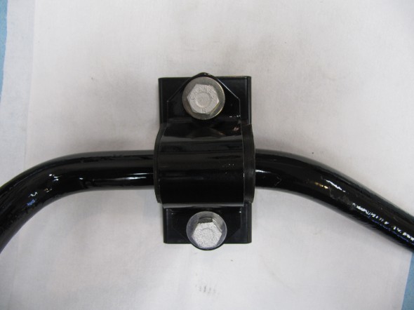
Anti Roll Bar Frame Mount

Anti Roll Bar Frame Mount
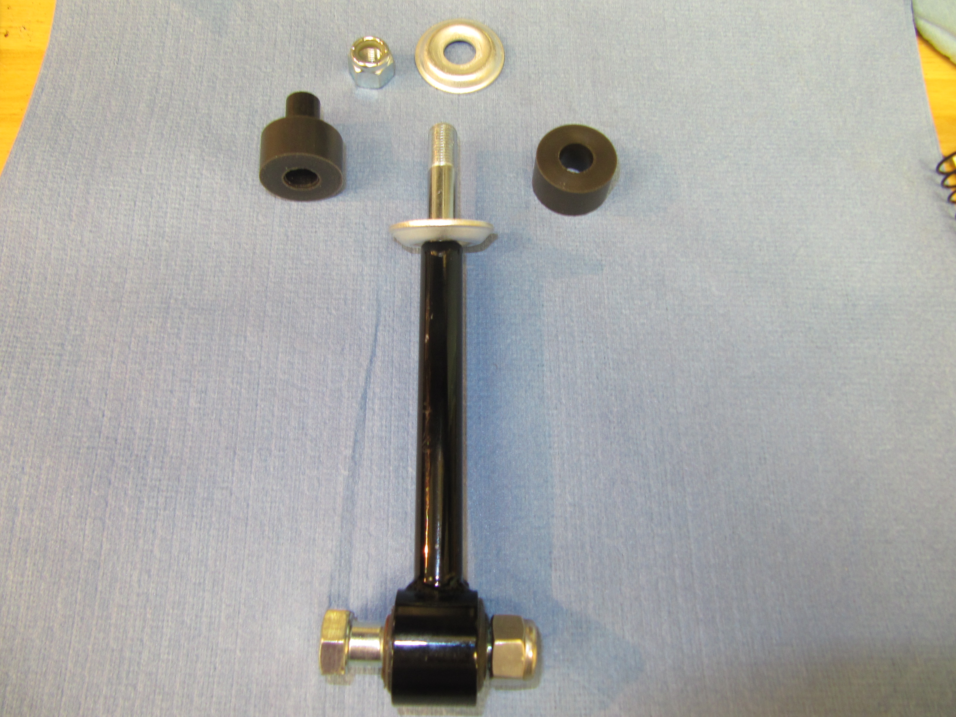
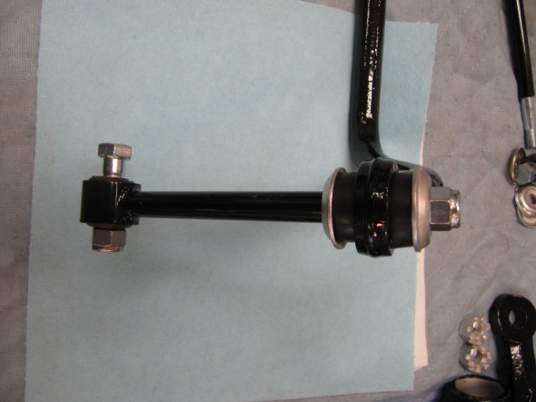
The Link, Between Anti-Roll Bar And Coil Spring Seats secures the ends of the anti-roll bar to the suspension.The Link assembly is comprised of rubber (poly) bushes in the eye end of the links, with 7/16” x 1 3/4” – 20 bolts and 7/16″ – 20 nylock nuts connecting the Link to the Coil Spring Seats.
Each Link connects to the anti-roll bar with two rubber (poly) pads, a distance tube through those pads on the link shaft, and two retaining washers, all held in place with a 3/8″ – 24 nylock nut.

Anti Roll Bar Link with Poly Bushing

ARB Link with Hardware
ARB Link Installed
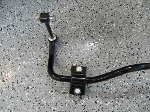
Anti Roll Bar & Fasteners

Complete Anti Roll Bar and Fasteners
Front Hubs, Bearings and Brake Rotors
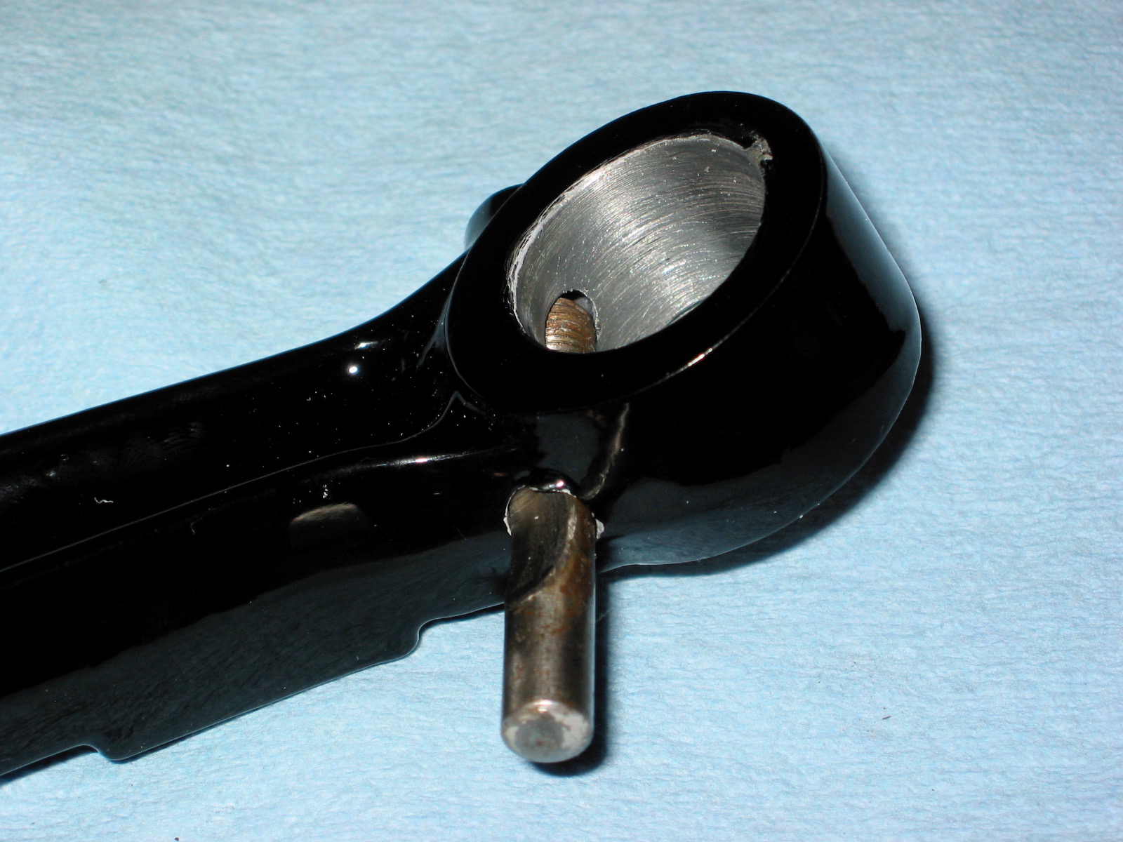
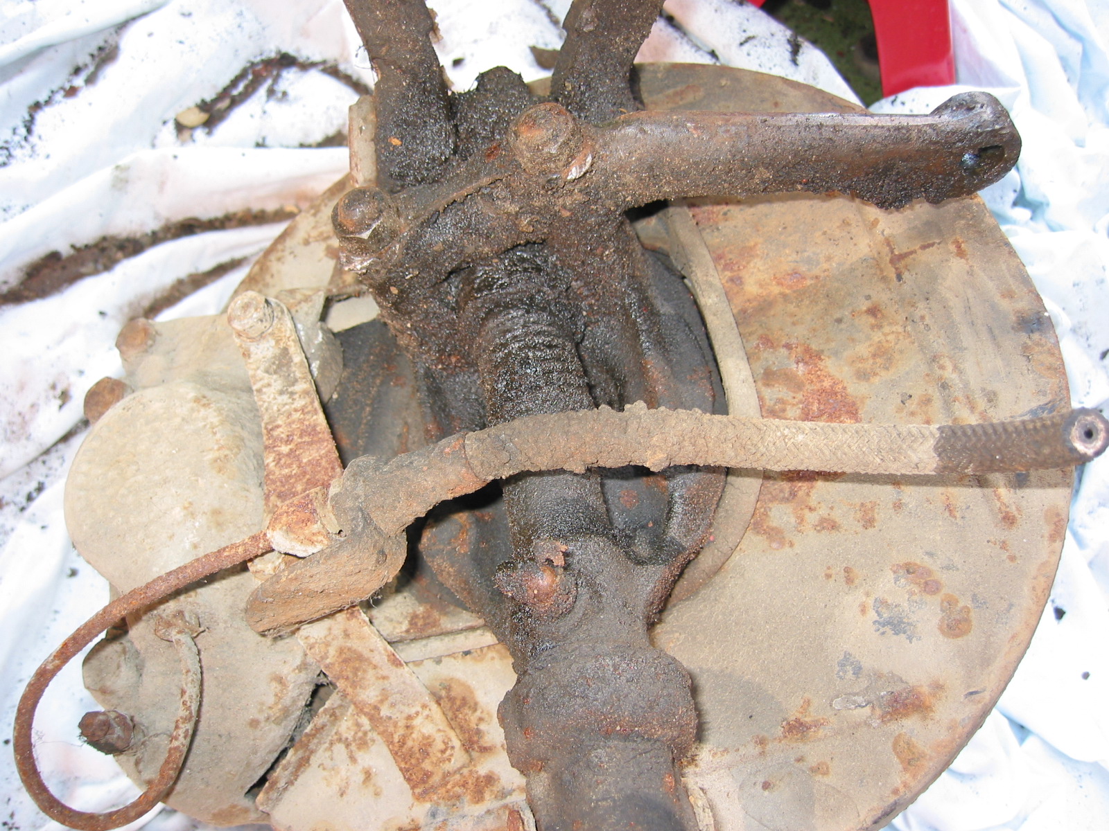
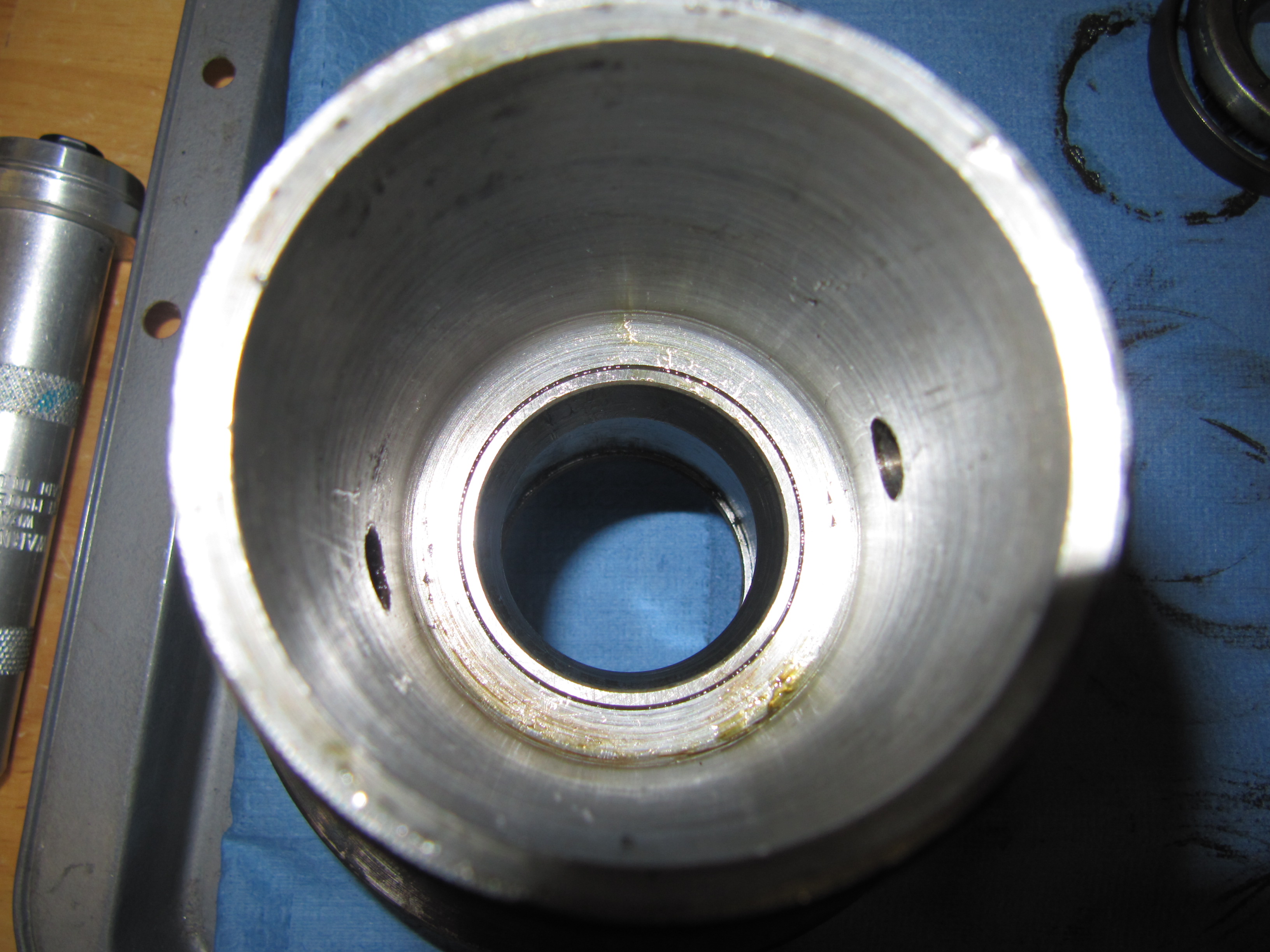
After disassembling one of the original front hubs to see how the various components were assembled in the hub, I reassembled the new RH and LH front hubs.
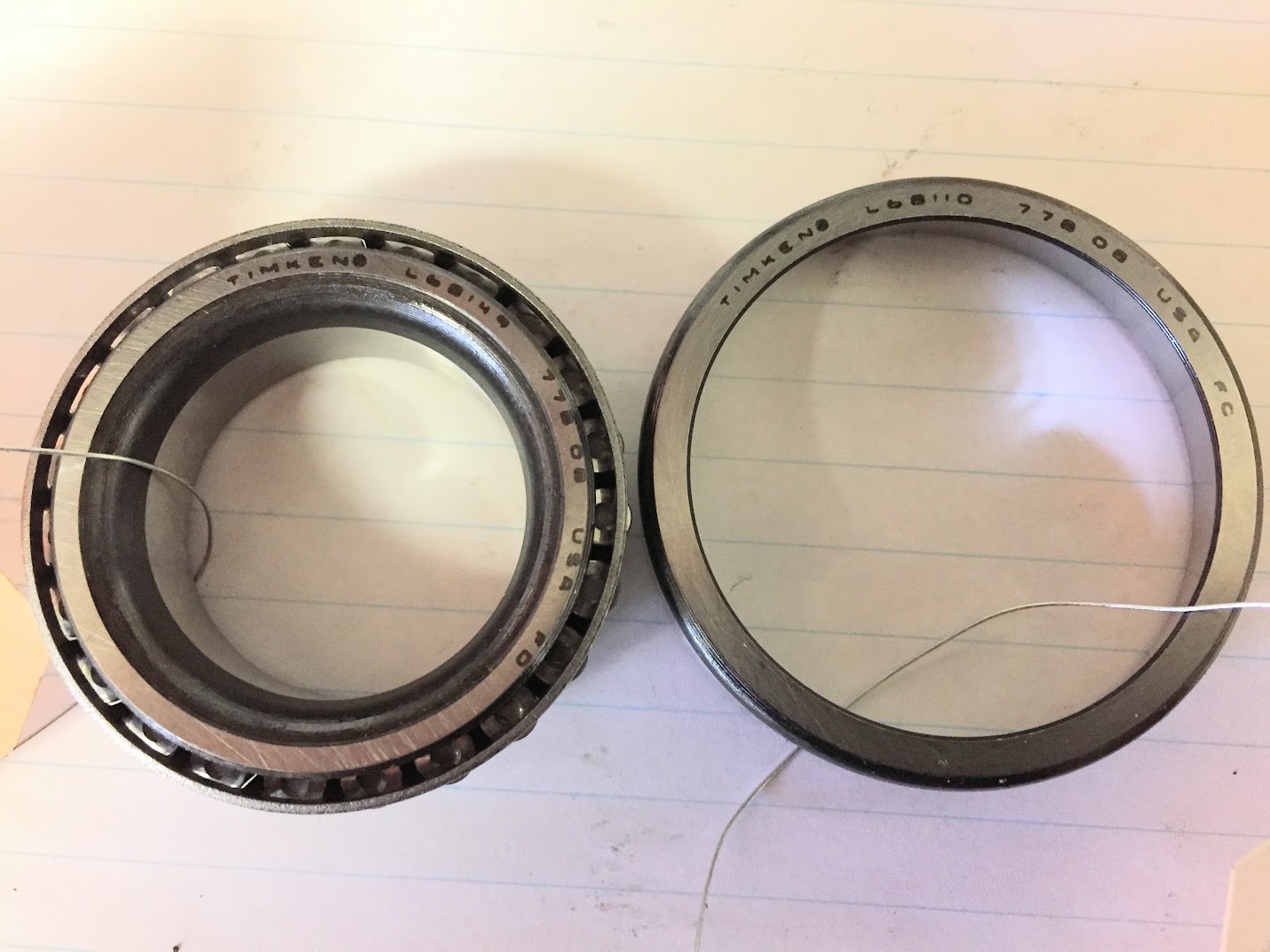
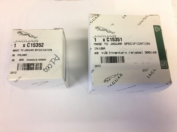
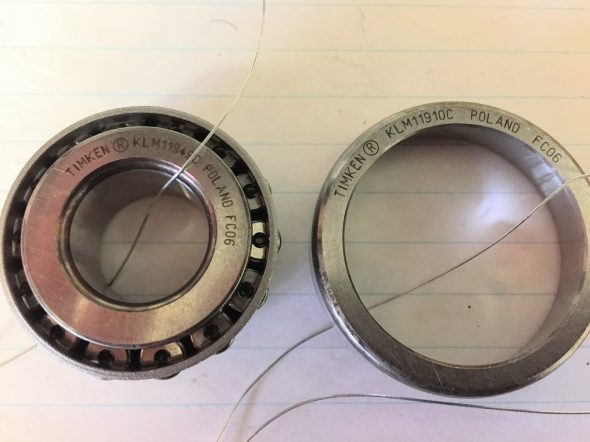
These are the inside and outside bearings with races for one front hub. SNG Barratt sells two grades of these bearings with the more expensive being genuine Jaguar parts made by Timken. I opted for the more expensive Timken bearings that match what was used originally. Curiously, the outer bearings were made in Poland, while the inner bearings were manufactured in the USA – go figure. The thin wire in the images below is for a label indicating RH and LH sides. Making sure that you keep the bearing and bearing race pair together is important. I marked these because all of the races went into the freezer to slightly “shrink” them making it easier to install in each hub.
MK2 front hub Timken Inner and Outer Bearings

MK2 Front Hub Timken Inner Bearings
MK2 Front Hub Timken Outer Bearings
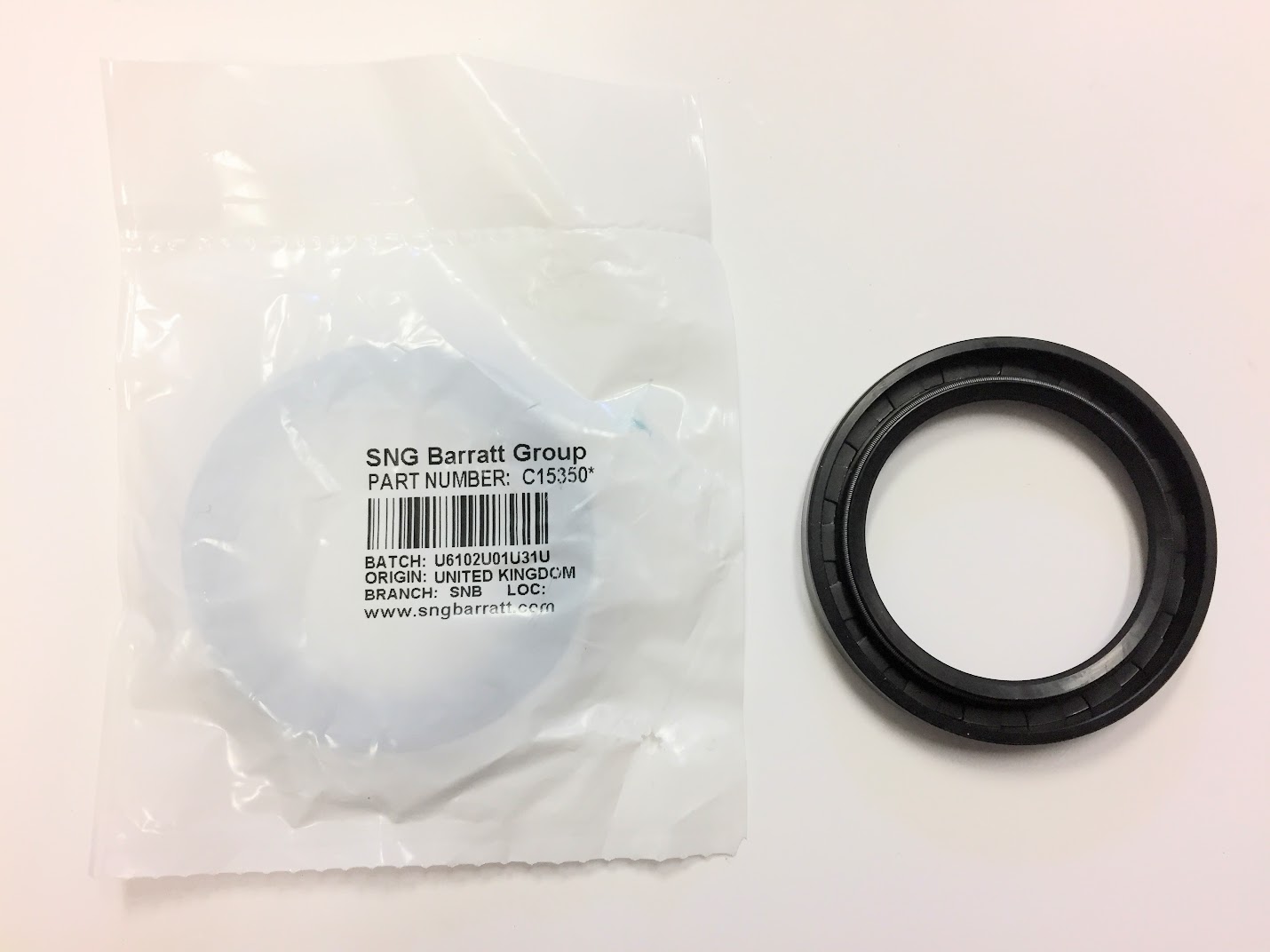
New rubber seals were also ordered from SNG Barratt.
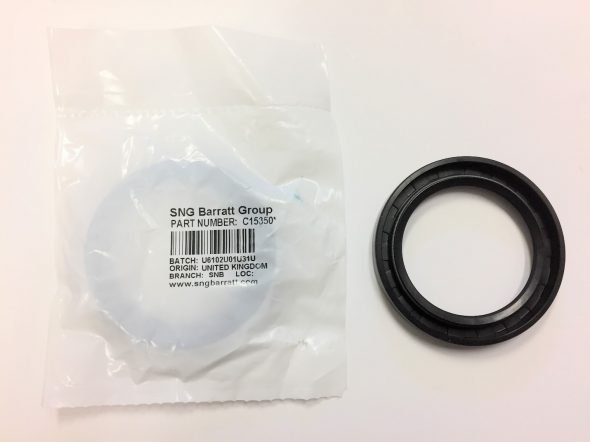
MK2 Front Hub Bearing Seals
I then installed the inner and outer bearing races in each hub again being careful to keep the bearings paired with their matching races. I tapped them home with an aluminum driver as seen in the image below. I then smeared each race with a light coat of grease to protect the surfaces.
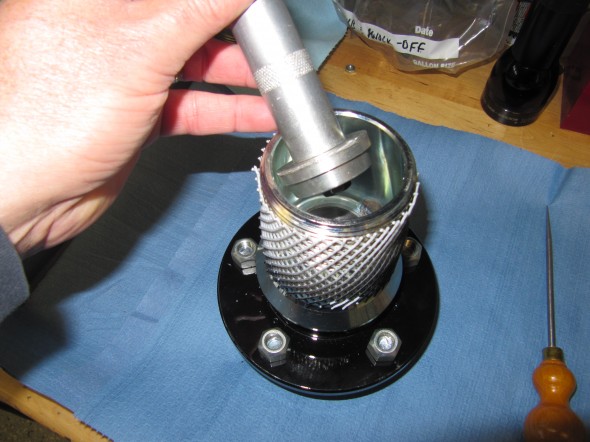
Outer Race Install

Outer Race in Place
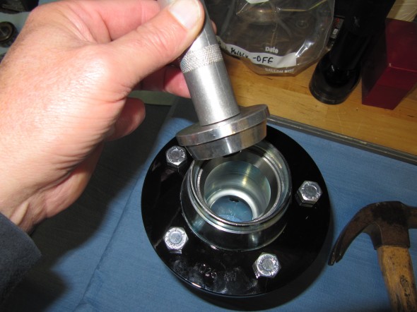
Inside Race Install
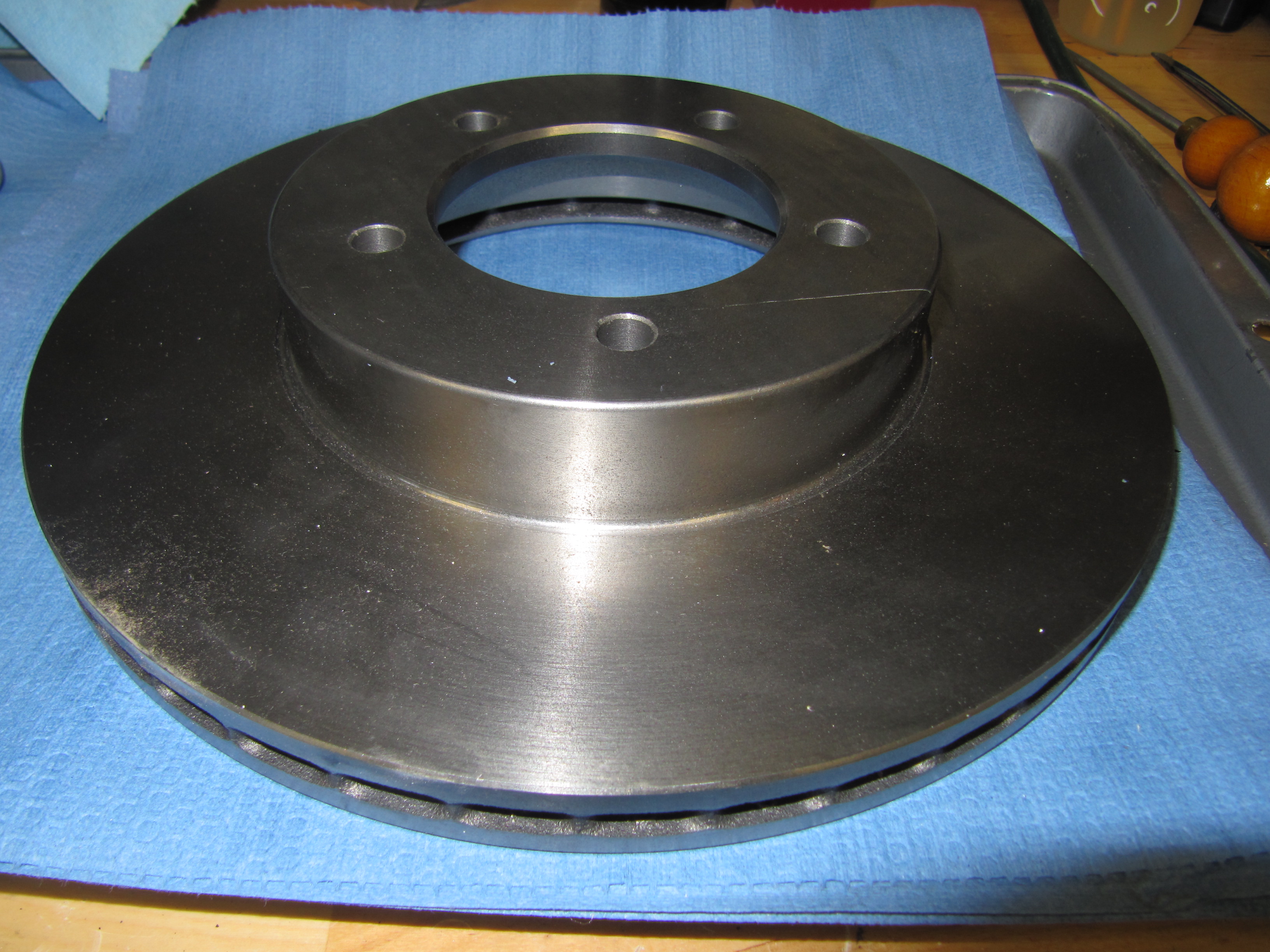
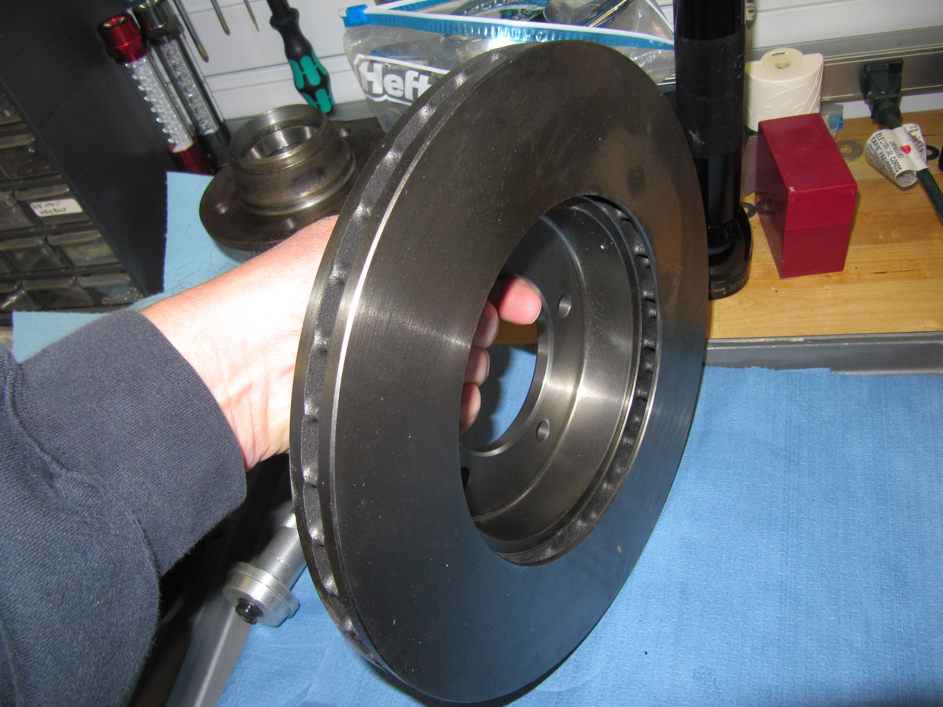
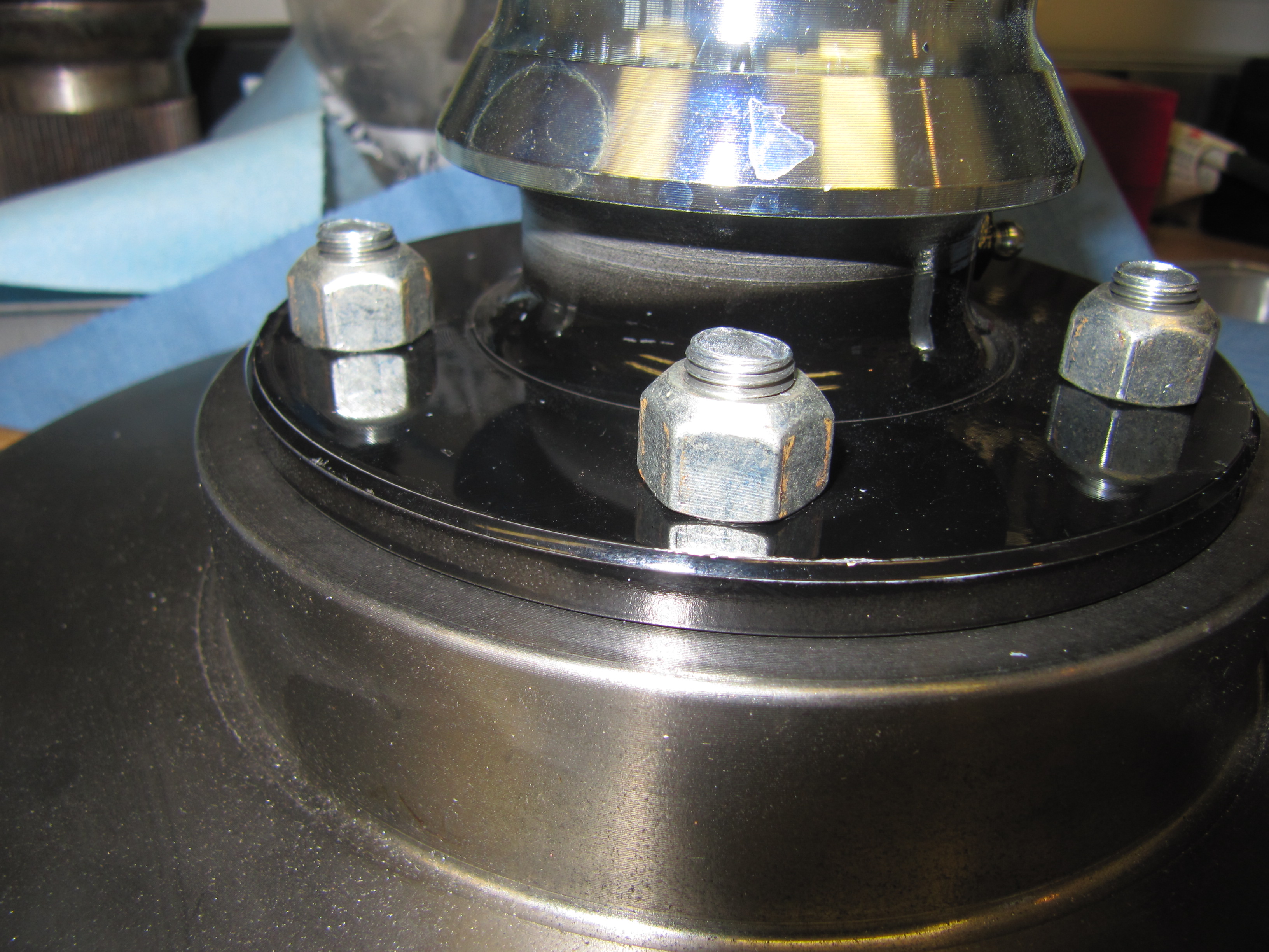
The next step was to install the brake rotors to the hubs. I purchased a brake upgrade kit from Coopercraft that uses ventilated rotors in the front. The upgrade is discussed further in the “Brakes” section of the blog https://valvechatter.com/?p=2330 . For now, I have just bolted the rotors to the hubs. Each hub/rotor requires five 7/16″ x 1 5/16″ – 20 bolts and five 7/16″ – 20 hub nuts.
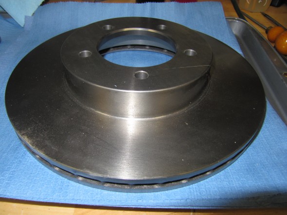
Vented Brake Rotor 1

Outer Race Install
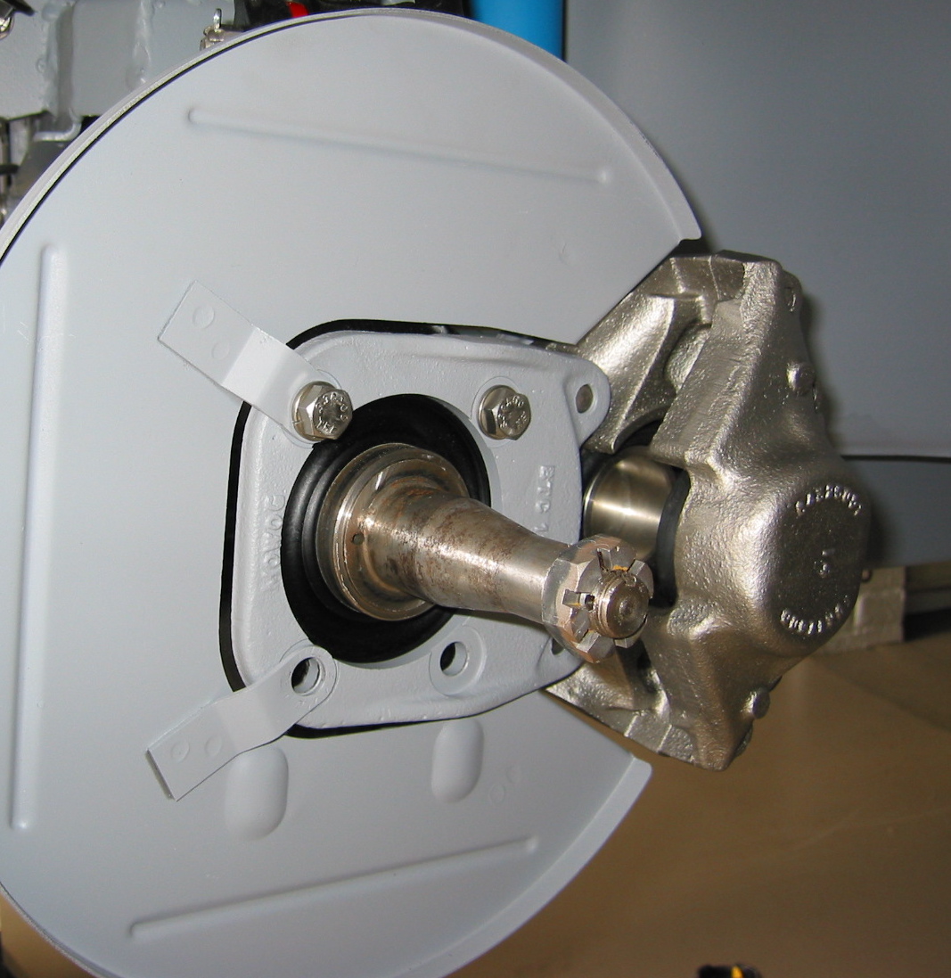
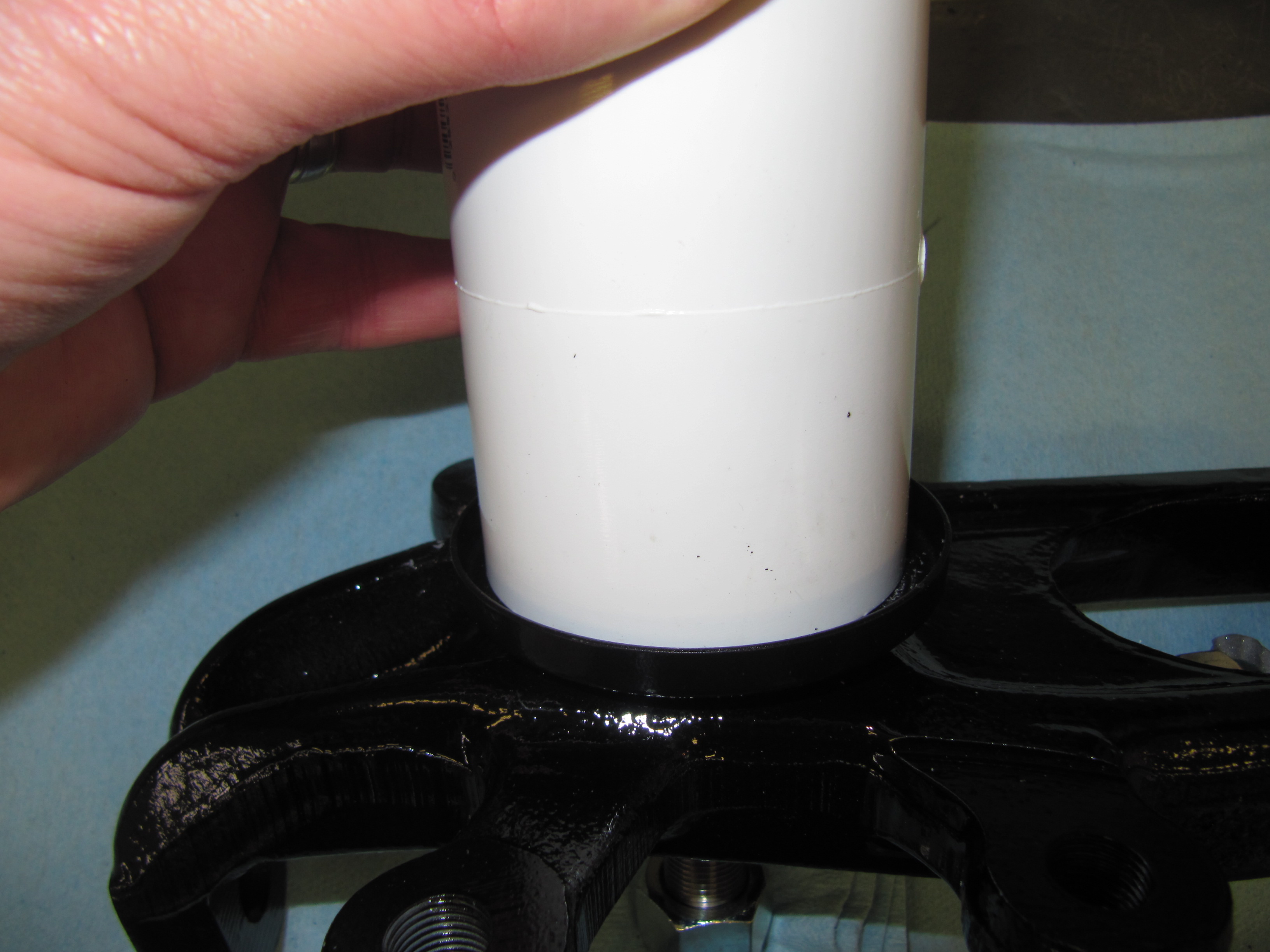
Hub Water Shields
The water shields are a press on fit, but I found them to be quite tight and they needed a little persuading. I used a piece of PVC pipe to drive home the water shield on the stub axle carrier.
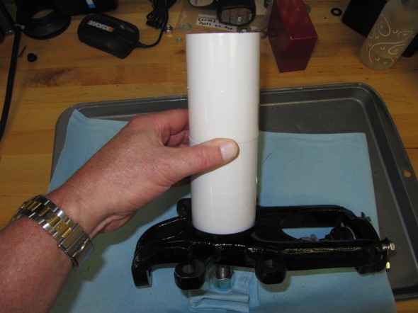
Water shield install 1

Water shield install 2
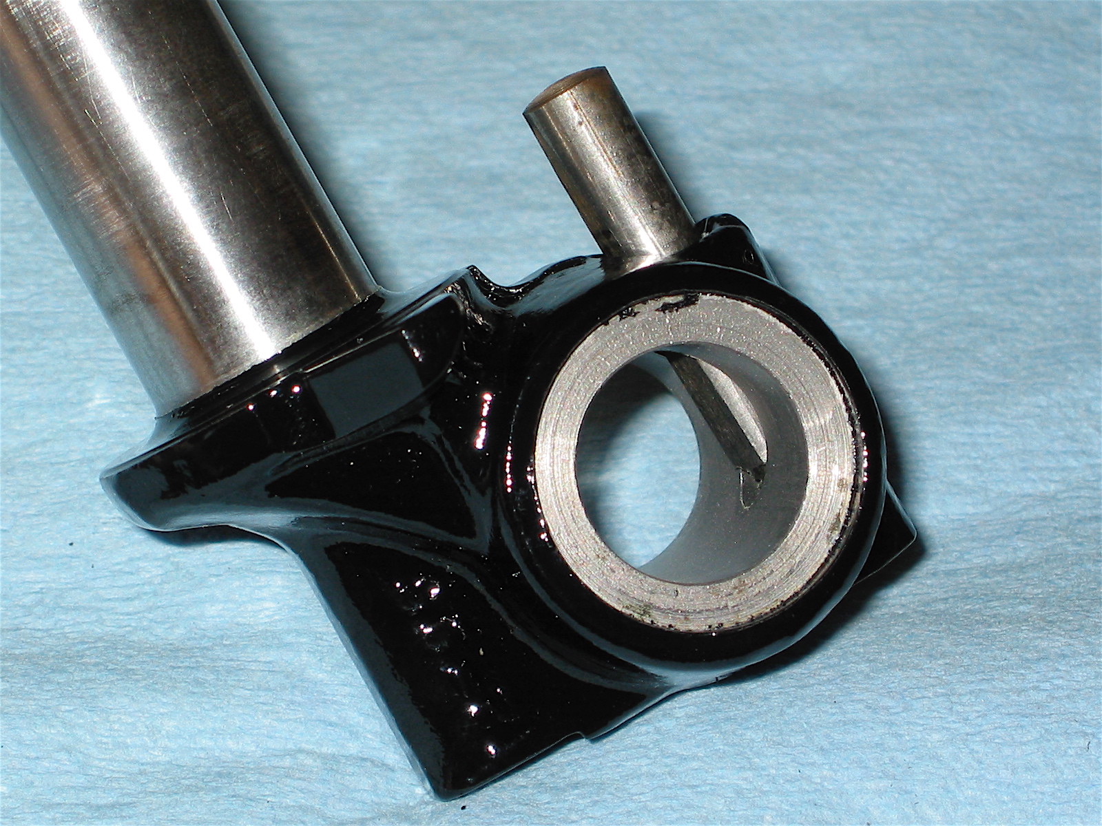
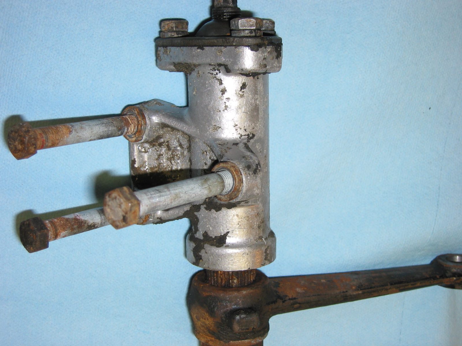
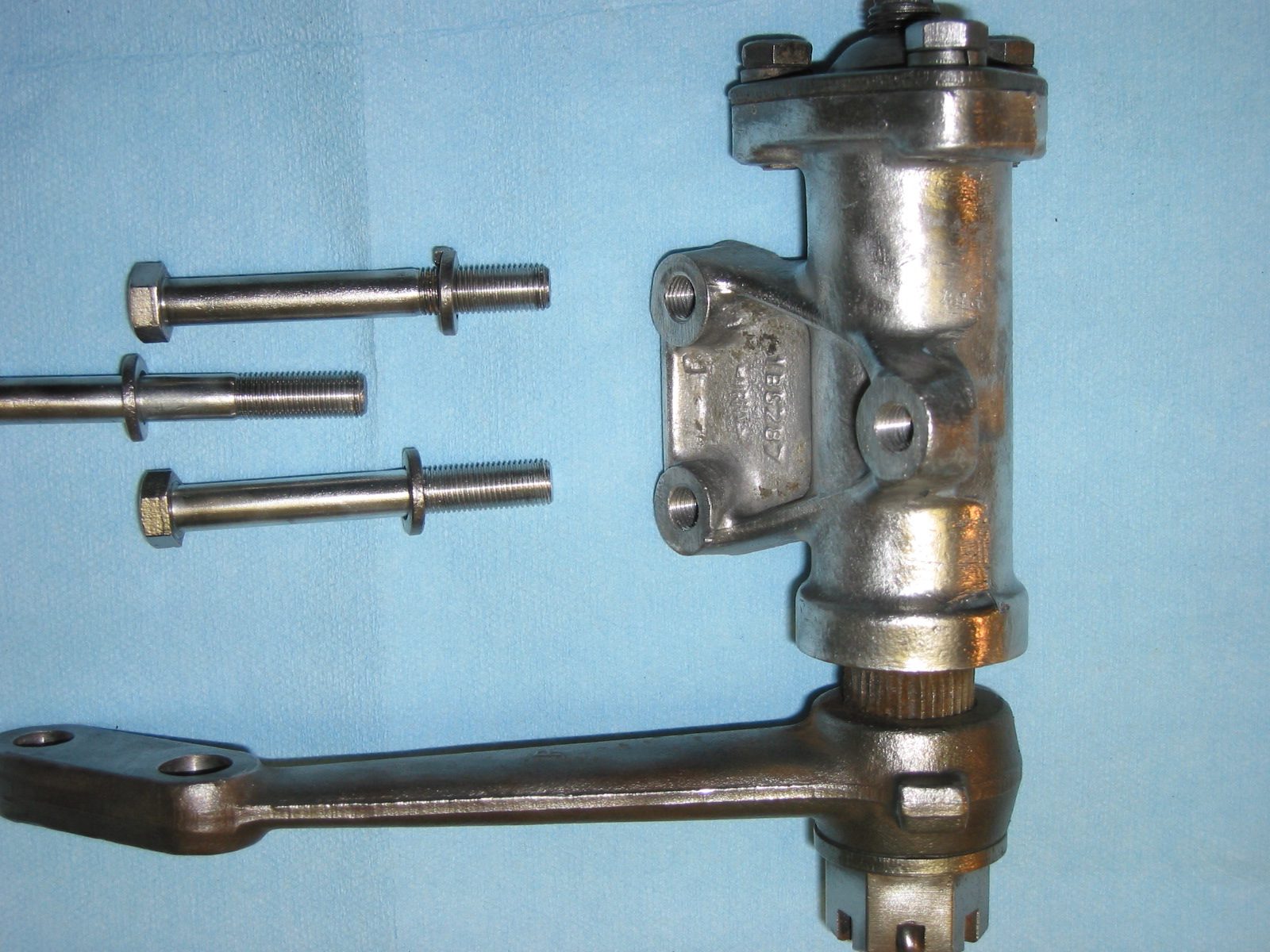
The Stub Axle Carriers
The stub axle carriers were then fit to the upper and lower wishbones.The upper ball joint is inserted into the locating hole at the top of the carrier and is secured with a 1/2″ flat washer and a 1/2″ – 20 nylock nut. The lower ball joint is inserted in the lower locating hole of the stub axle carrier and is secured with a 9/16″ flat washer and a 9/16″ – 18 nylock nut. The carrier was loosely fitted and will be tightened when the front suspension cross member assembly is mounted to the car and the hubs are installed.

Axle Carrier Upper Mount

Axle Carrier Lower Mount

Stub axle carrier mounted
I lightly coated the stub axles with moly grease just as a rust inhibitor.
All the assembly processes described above were repeated for the other side of the front suspension cross member assembly. The next step is to attach the steering components to the cross member. That process is detailed in the Steering section of the blog under restoration.
Anti-Roll Bar
After installing the steering rack (See Entry 55) on the front suspension cross member, I attached both the RH and LH Anti-Roll Bar links to the coil spring seats by inserting one 7/16″ x 1 3/4″ – 20 hex head bolt through the coil spring seat bracket and the bushing in the link pin. The bolts were then secured by 7/16″ – 20 nylock nuts.

RH Anti-Roll Bar Link

Anti-Roll Bar Installed
Following installation of the anti-roll bar, I turned my attention to the front brakes and specifically the brake calipers that mount to the stub axle carrier. This work is detailed in the Brakes entry under restoration.
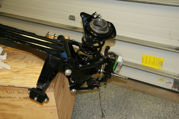
Complete Front Suspension Assembly
Well, not quite. While the brakes calipers, hoses, and the steel lines for the power steering have been added, the front hubs, rotors and springs are yet to be installed.

Front Suspension Assembly Complete, sans Hubs & Rotors
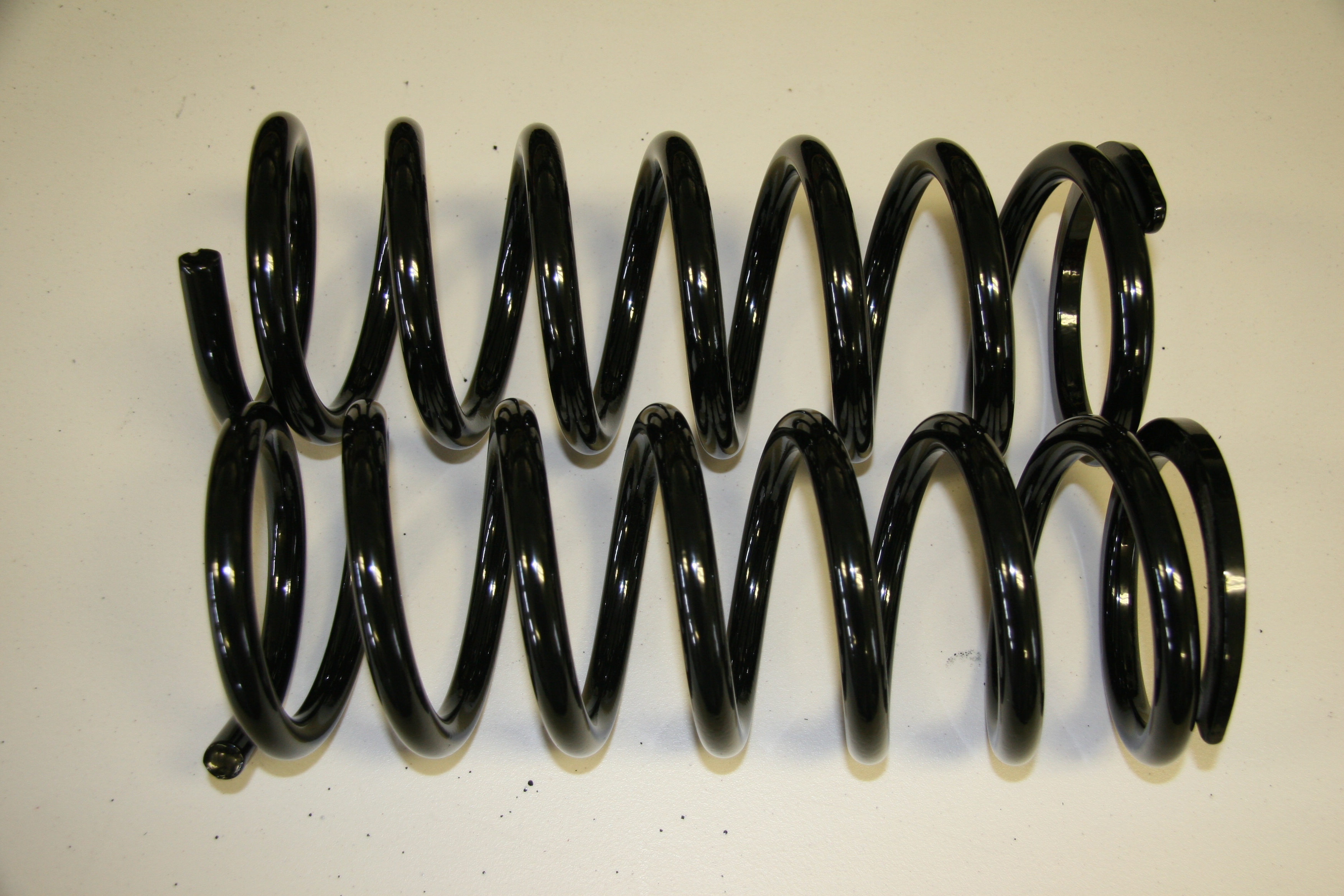
While I painted the assembly, I powder coated the coil springs. I had thought about replacing the originals with a “sport” spring, but I decided to go ahead and try the originals again. I will evaluate the ride and then see if I want to switch out to stiffer springs. Whether the powder coating permanently and adversely affected the temper of the springs is unclear. Some have advised going ahead without fear of problems, others (with some good background material) suggest that exceeding 350 degrees F harms the spring and will hurt handling. My plan is to proceed with the original springs and if I find that I have negatively affected the springs then I will just have to remove them and substitute new springs from one of the typical parts vendors.
Apparently three different springs were used on the MK2s. Some of the springs required ring spacers or packing. Glenn Logan from the Saloon-Lovers Forum reported that packing pieces – or ring spacers – are available from SC Parts in the UK ( Part no. 207969). Glenn indicated that his car rode to high after installing his springs. As a remedy his plan was to cut his springs. Dave Moore suggested that instead of cutting springs, one could drop the spring pan and accomplish the same thing. Get longer hardened bolts for the lower spring pan.
“Put a couple of washers between the spring pan and the wishbone there by dropping the pan and using up some of the ‘extra’ length. A couple of washers makes a big difference. Don’t forget to use the hardened grade 5 bolts though!”
Jeff Smith who just replaced his springs contributed the following:
“Just went through the same thing on my Mk1. Ordered new
springs using the original part numbers and installed with
the original spacers. Car sat roughly 5” over the front
wheels. Pulled them out, cut off half a coil, reinstalled,
still 1” too high. Pulled out again, cut another 1/2 coil.
Just about right. Long process but well worth it. Since the
bottom of the spring is flatten out, the 2nd cut (making 1/2
cut increments) will be dramatically different.”
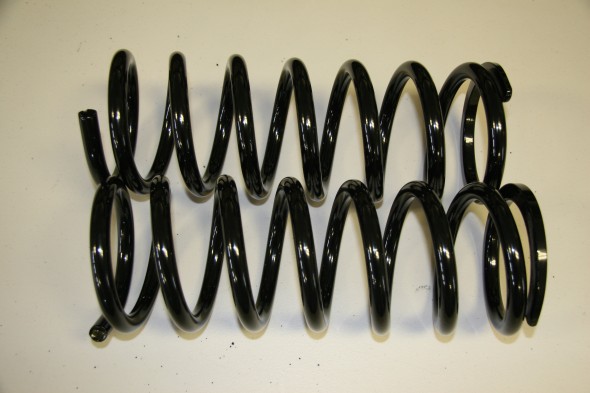
Powder Coated Front Coil Springs
Installing the Coil Springs
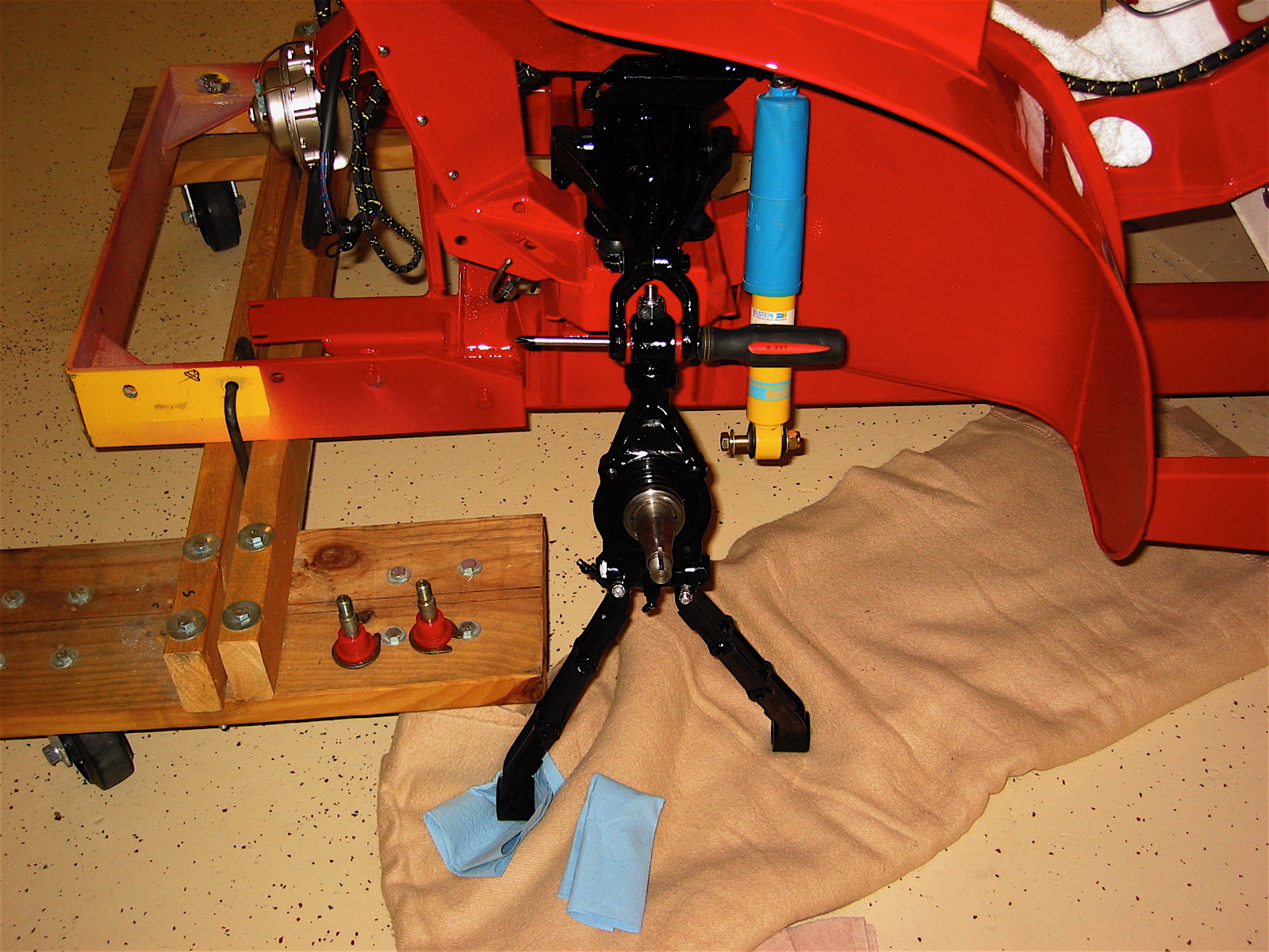
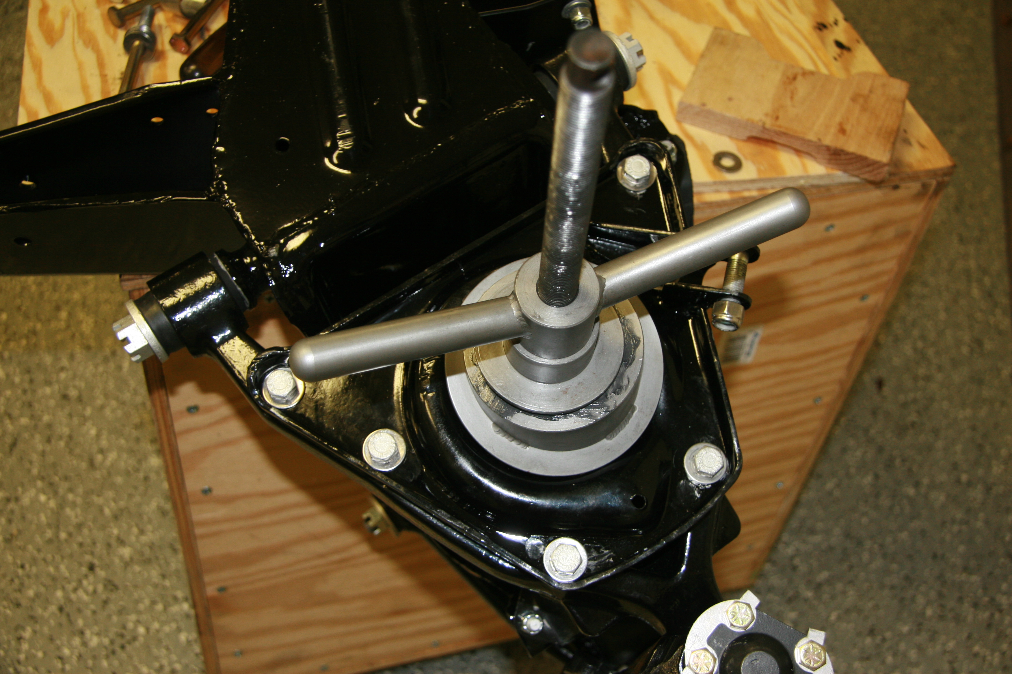
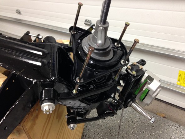
As stated above, I am going to try the original springs and see how they work out. To make it a little easier to maneuver the crossmember while installing the springs, I removed the rack and pinion assembly and the anti-roll bar. I then placed the crossmember assembly on a table (actually a wooden box with wheels) in an inverted position. The crossmember on the box looks precarious but in fact it is very secure.This way the coil spring seats are on top for easy placement of the compression tool. I borrowed the compression tool, modeled after the Churchill tool from a friend and it made the job much easier with fewer anxious moments than I had expected.
Crossmember on table

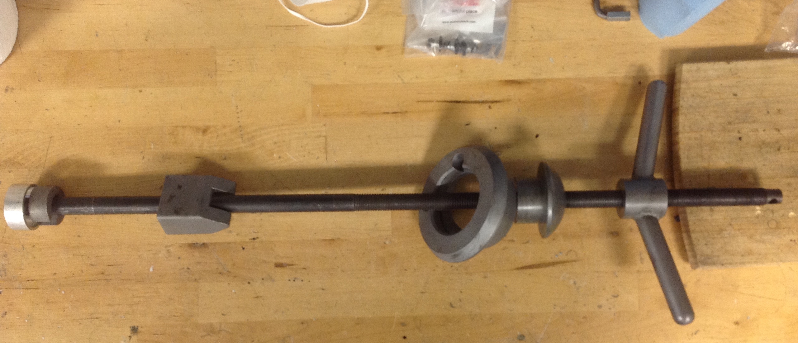
Coil Spring Compression Tool
This diagram illustrates the proper assembly sequence of the compression tool:
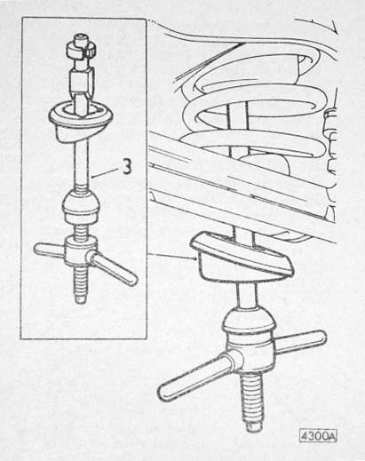
Coil Spring Compression Tool Diagram
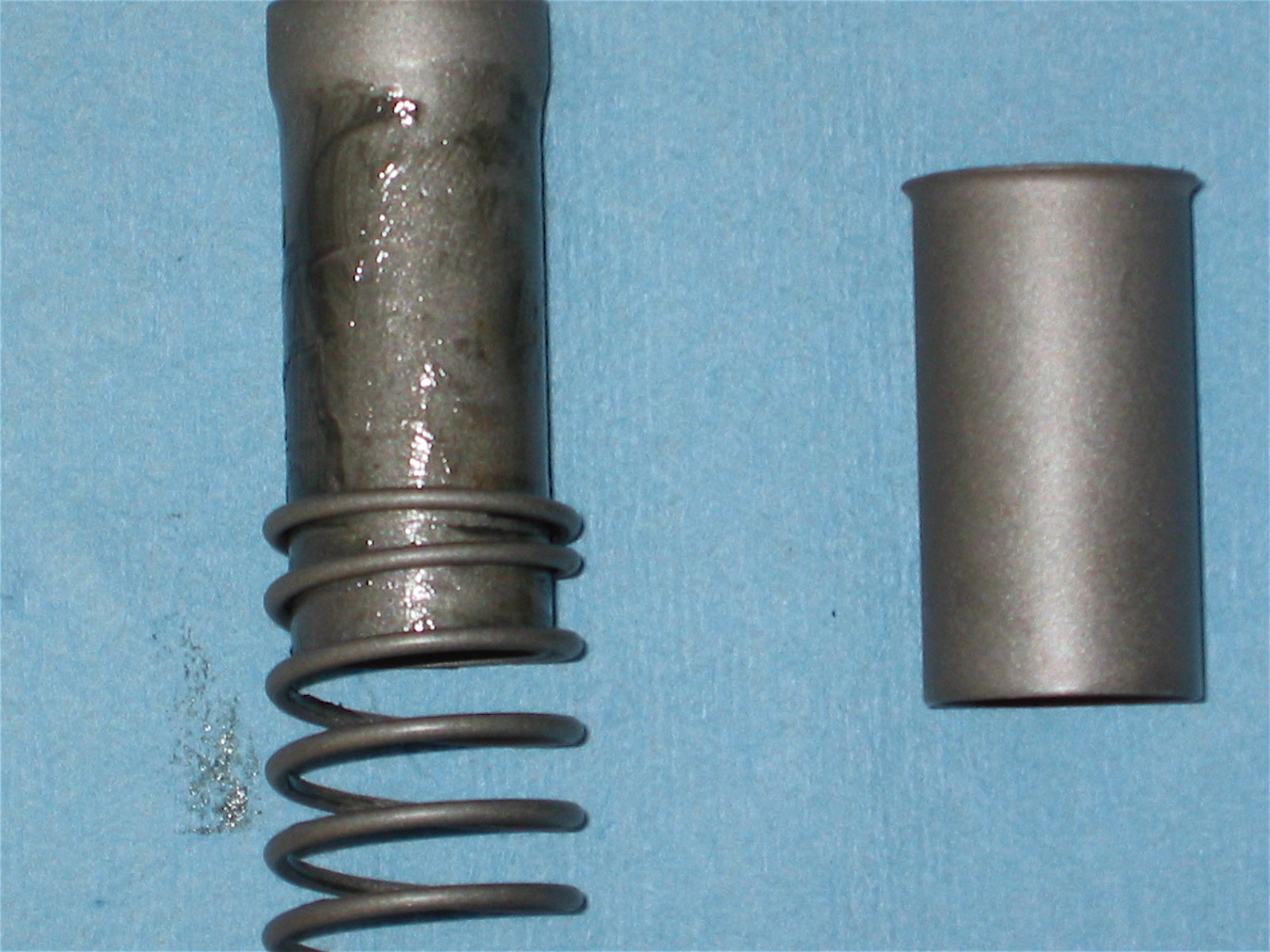
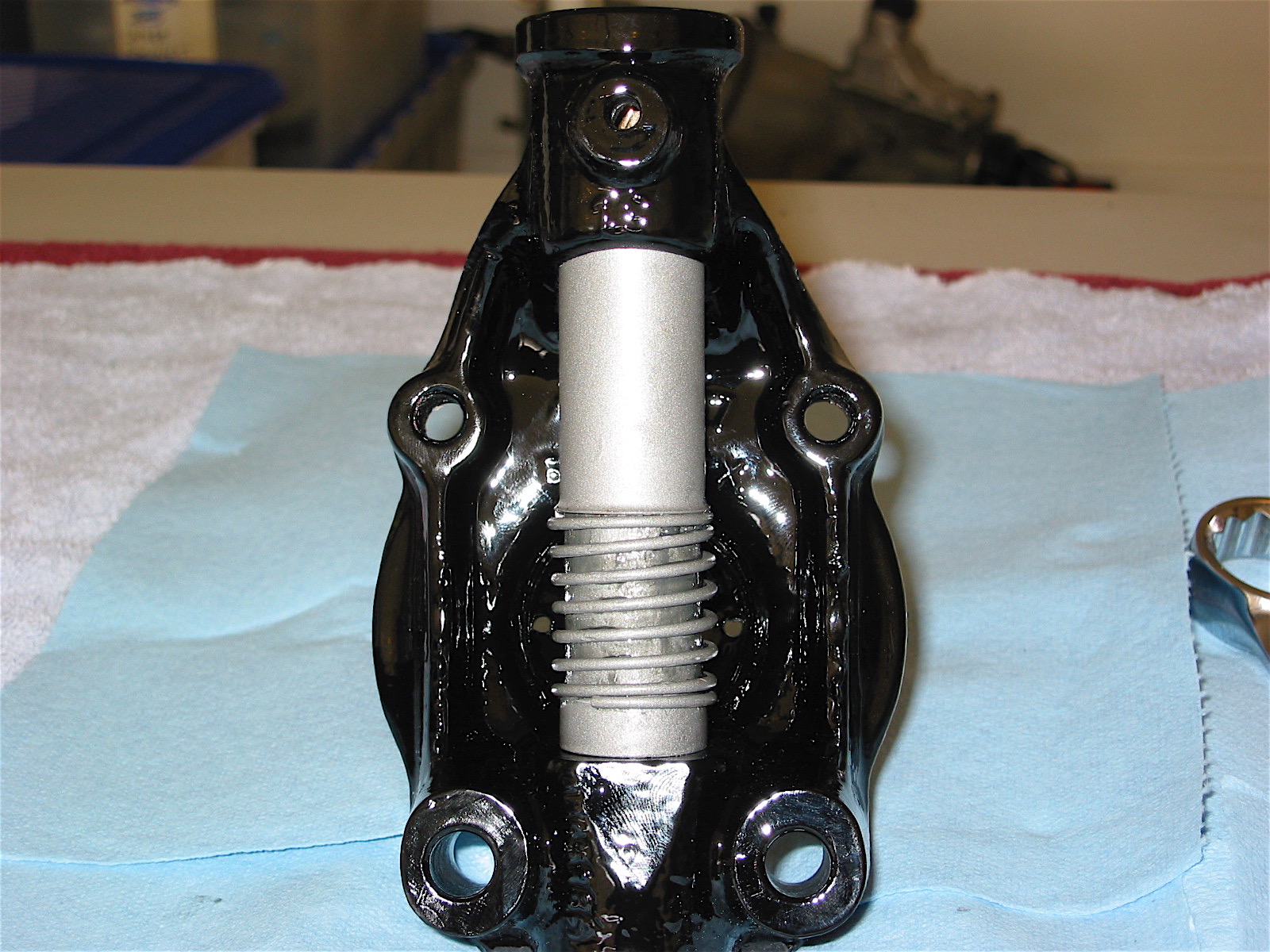
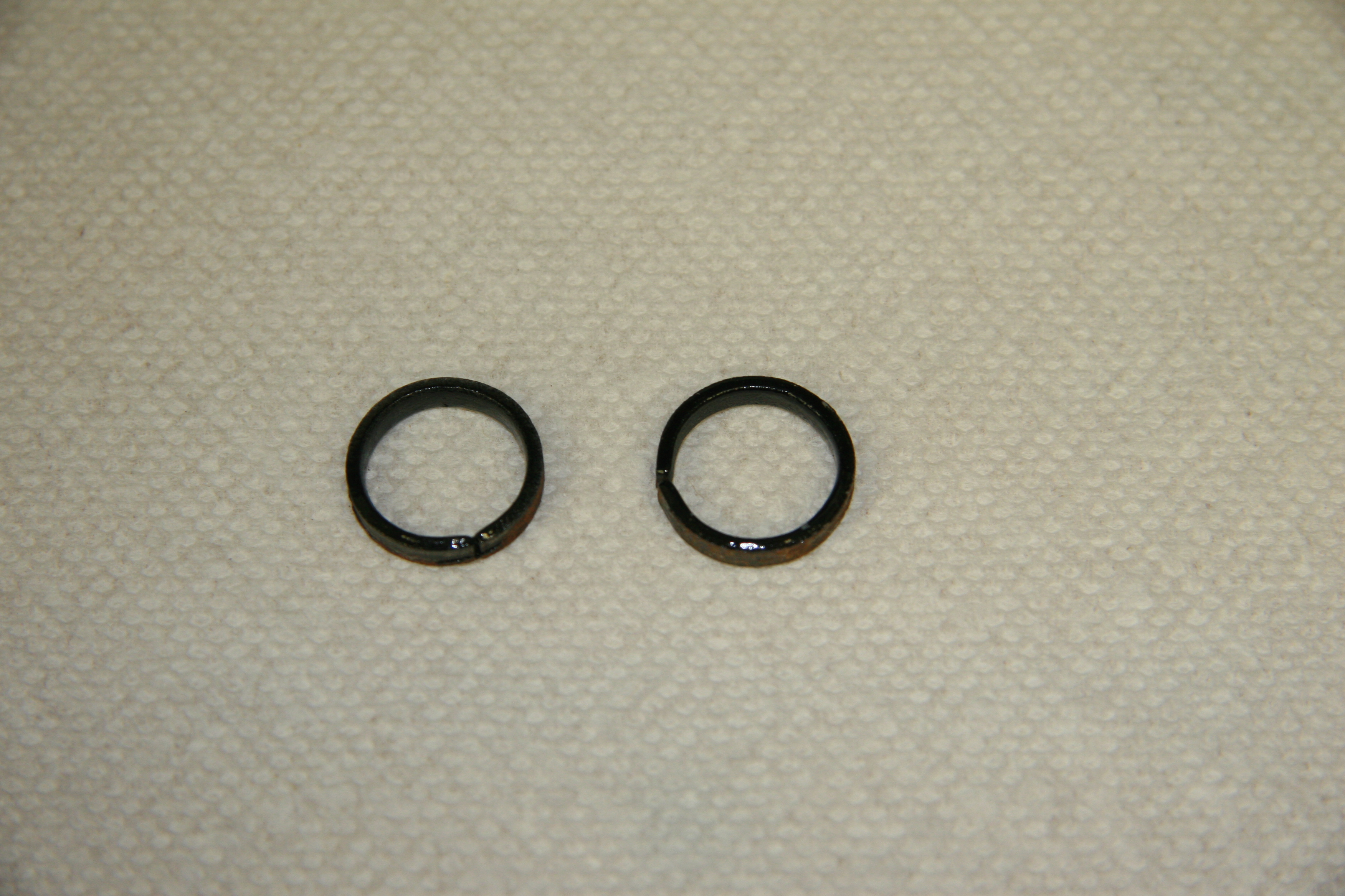
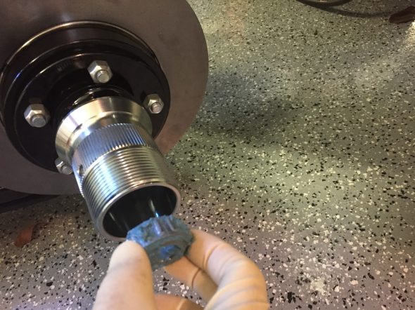
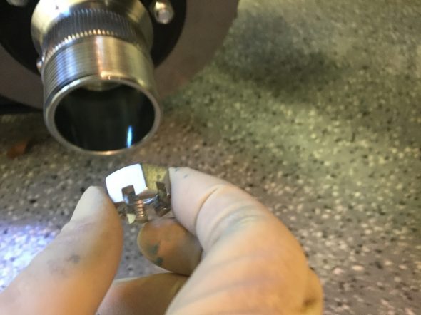
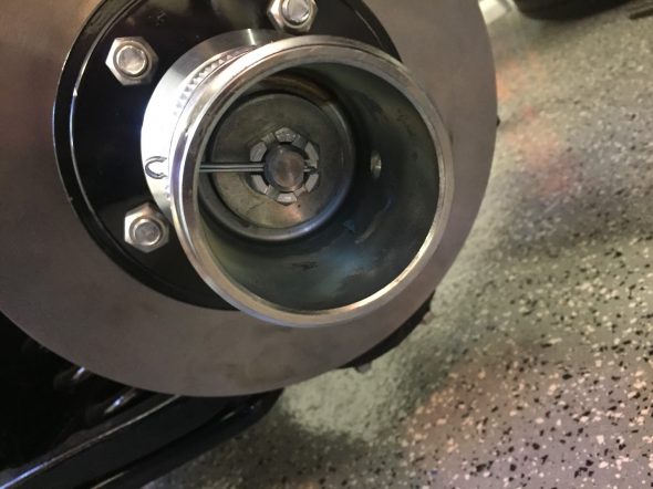
Prior to beginning the compression process, small ring spacers or as the Service Manual refers to them, “distance pieces,” must be tapped out of the turret. Otherwise the threaded shaft of the tool will not fit through the opening in the turret. These will be replaced before installing the shock absorbers as they are intended to reduce the diameter of the turret hole to fit the shock upper mounting shaft.
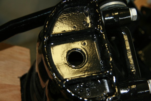
Distance Pieces located in the Turret
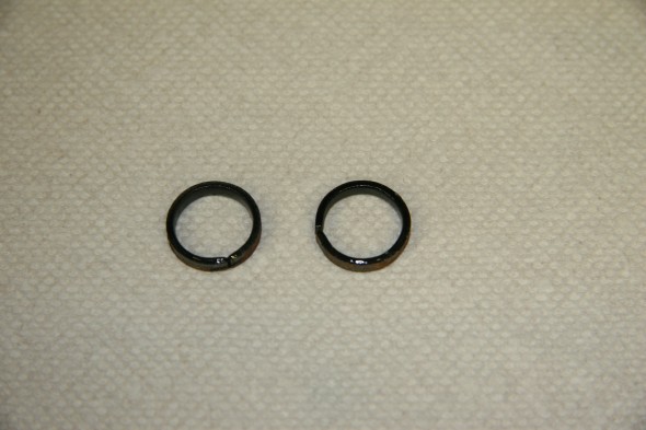
Turret Distance Pieces
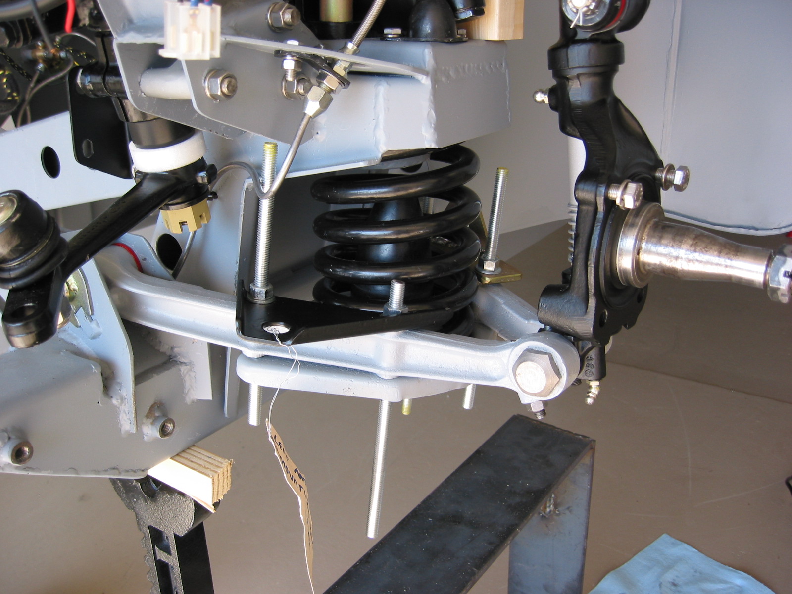
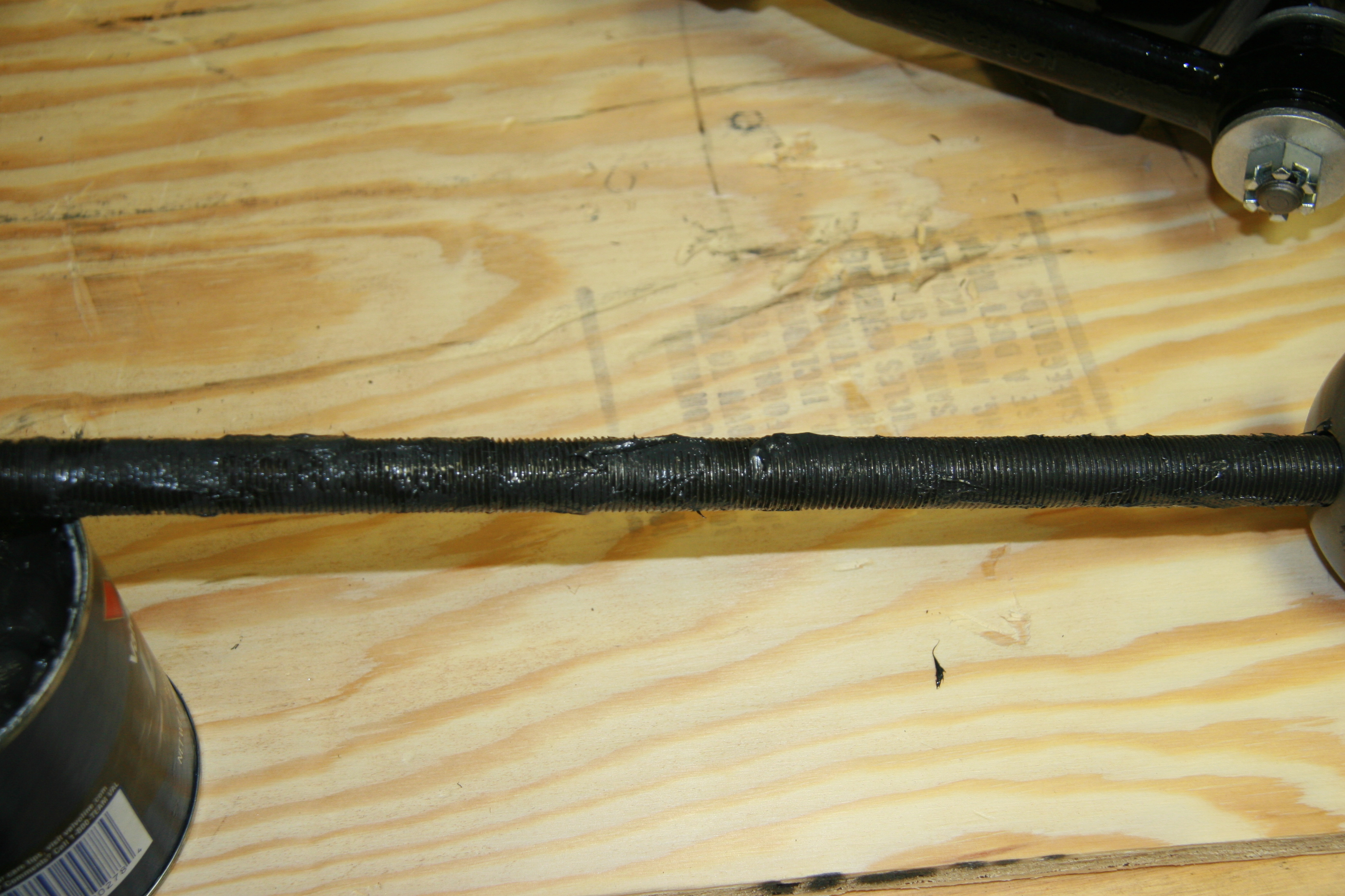
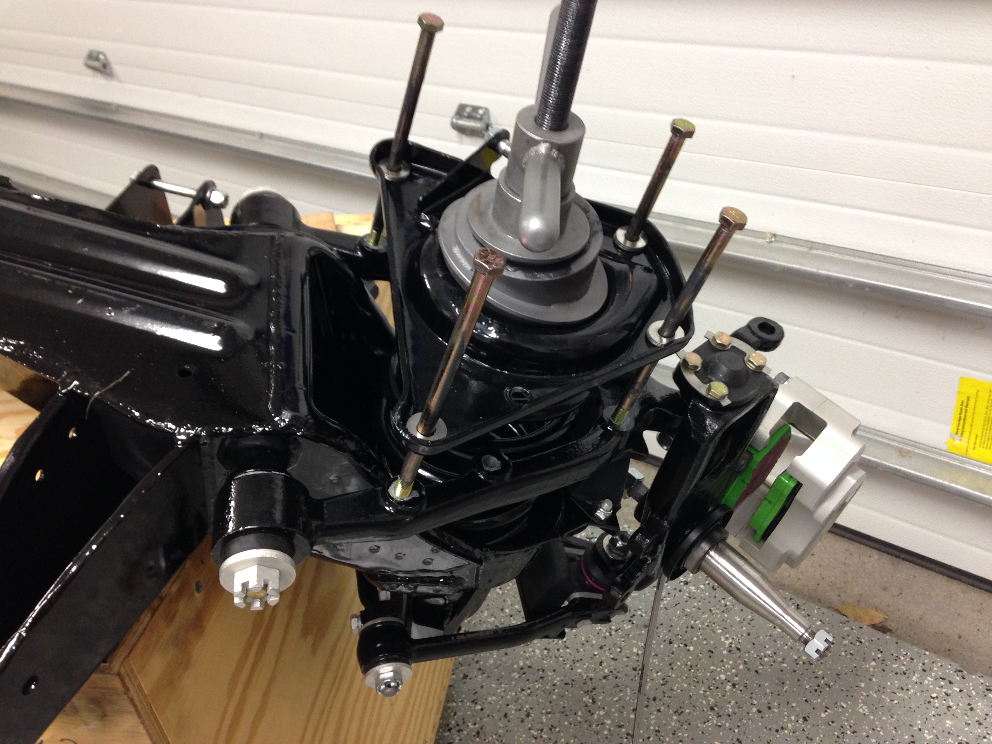
I liberally greased the threaded shaft of the tool as well as the surfaces of the upper two pieces of the assembly to reduce friction. While many others have suggested that only two alignment guide bolts are needed for the compression process, I used four. This involves a little more work but it also provides for a smooth compression of the spring seat. I also greased the bolt shafts. The entire procedure was uneventful.
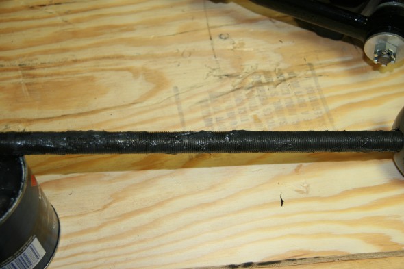
Greased threaded shaft
Tool Lock on Turret Top
Alignment Rods

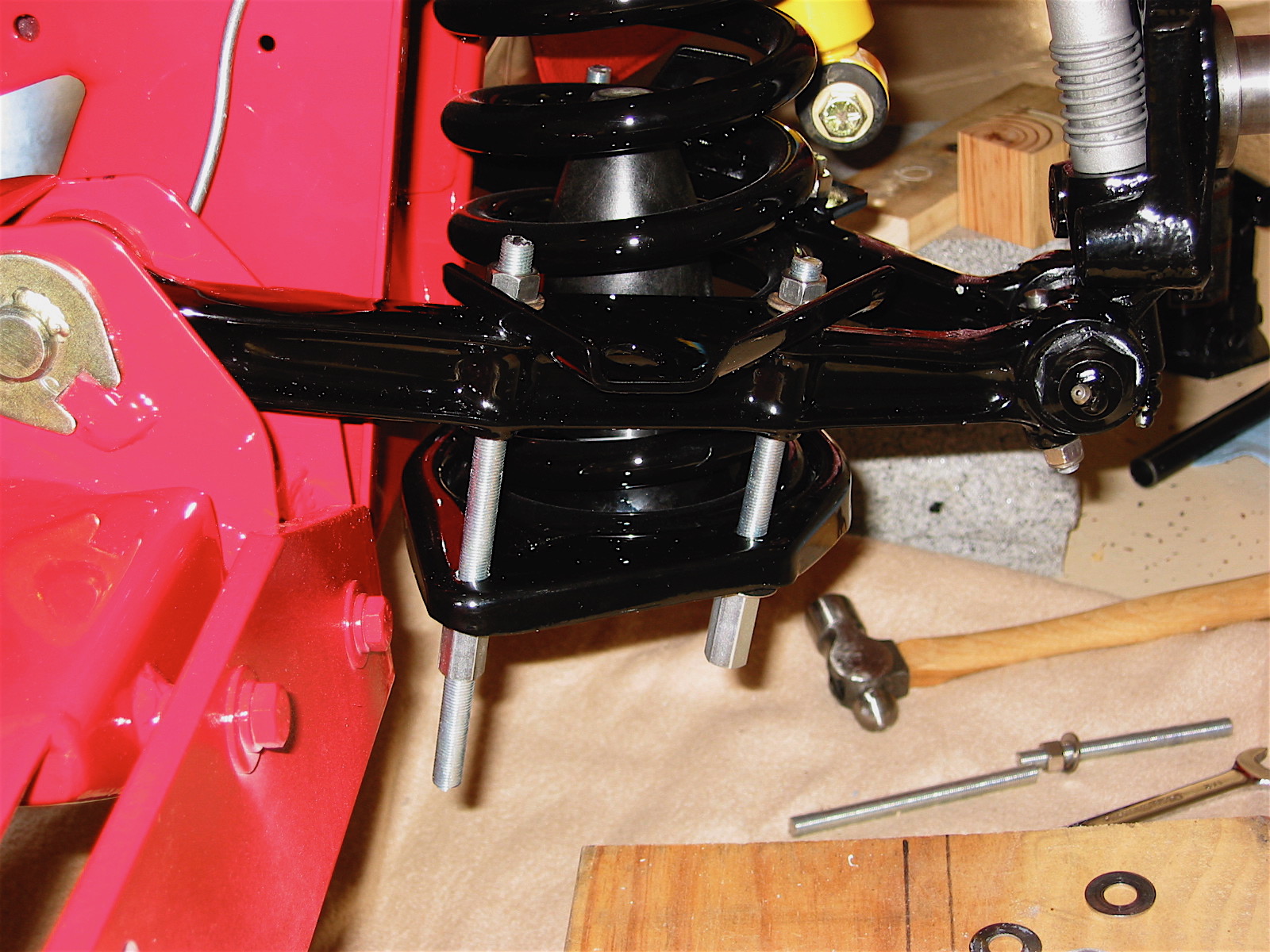
Bolts Securing Spring Seat
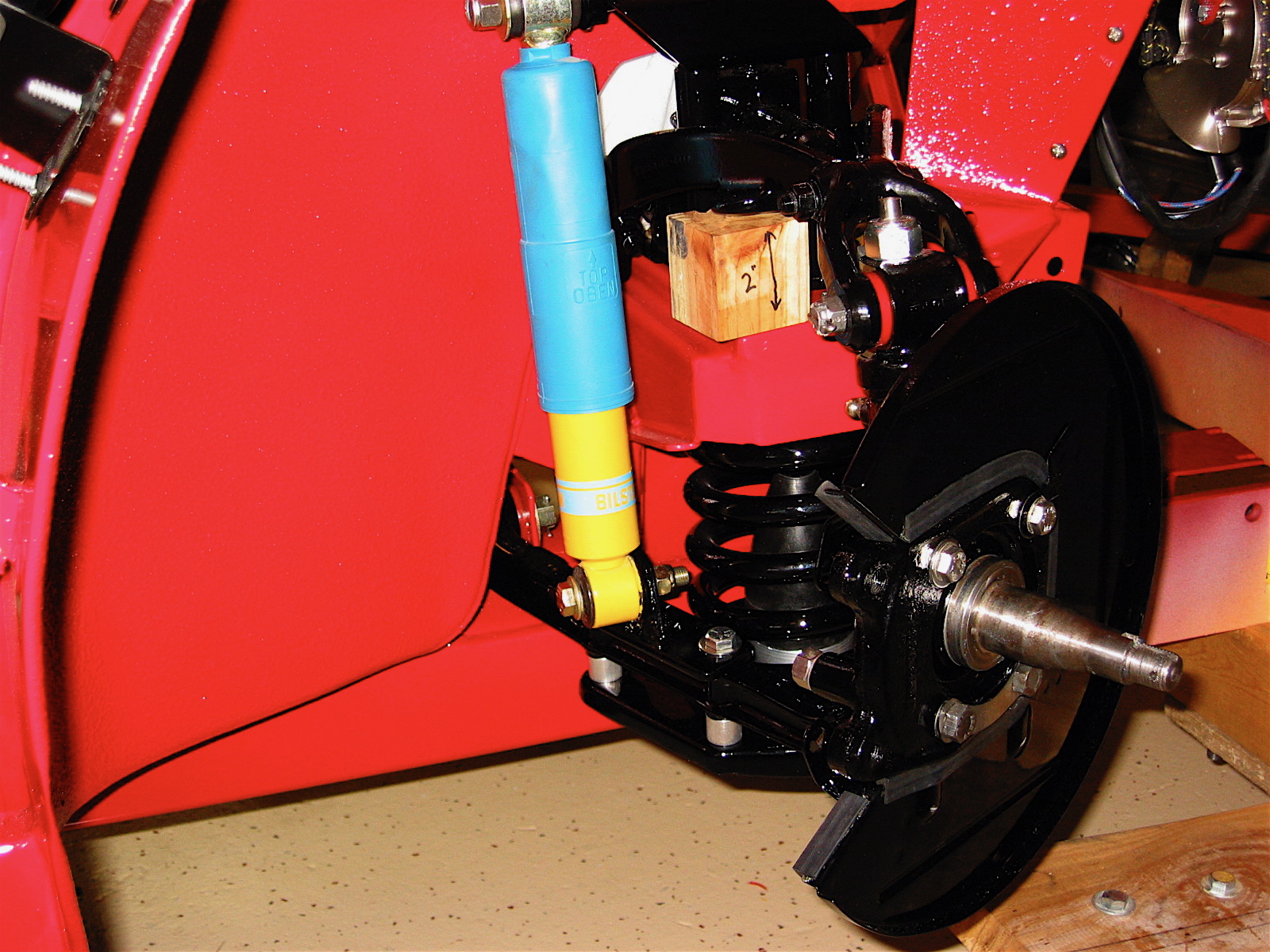
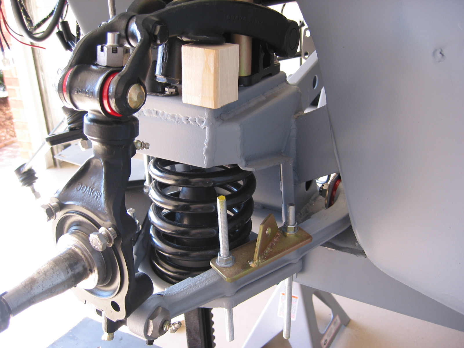
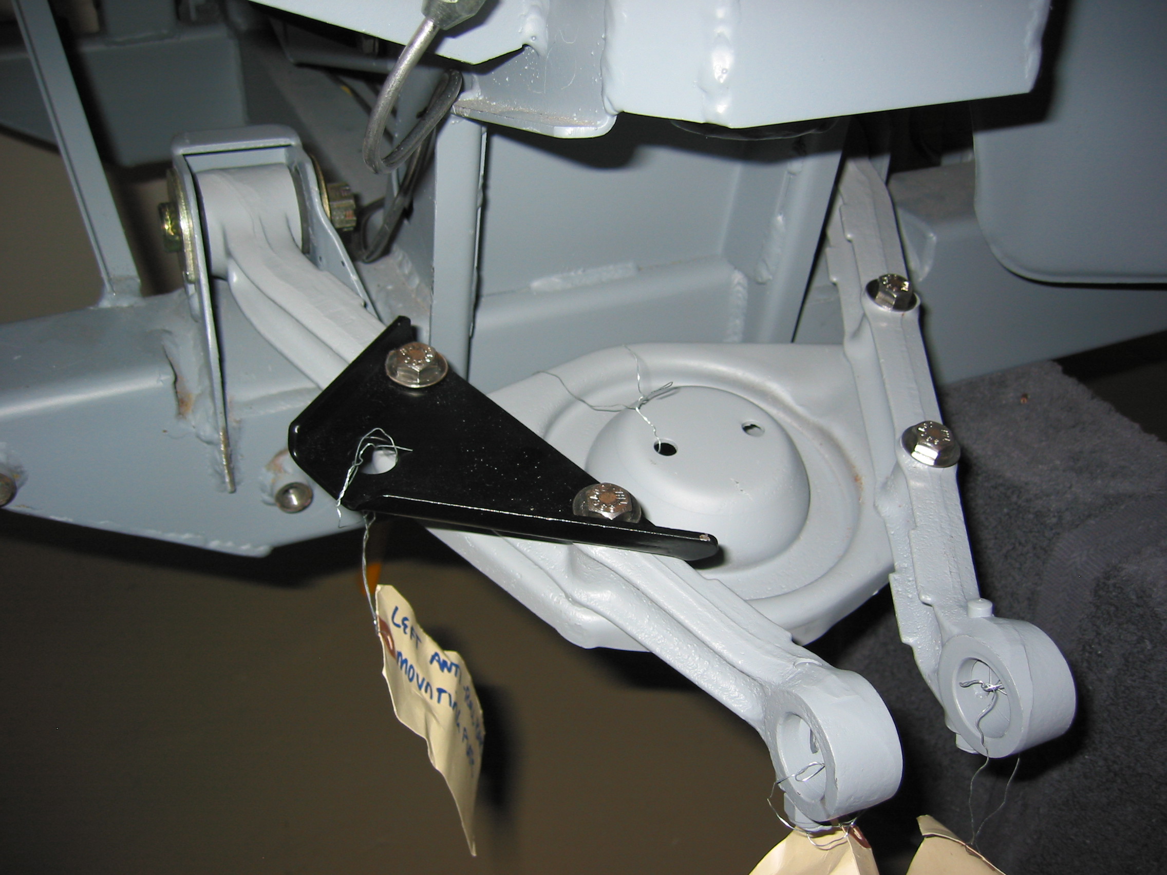
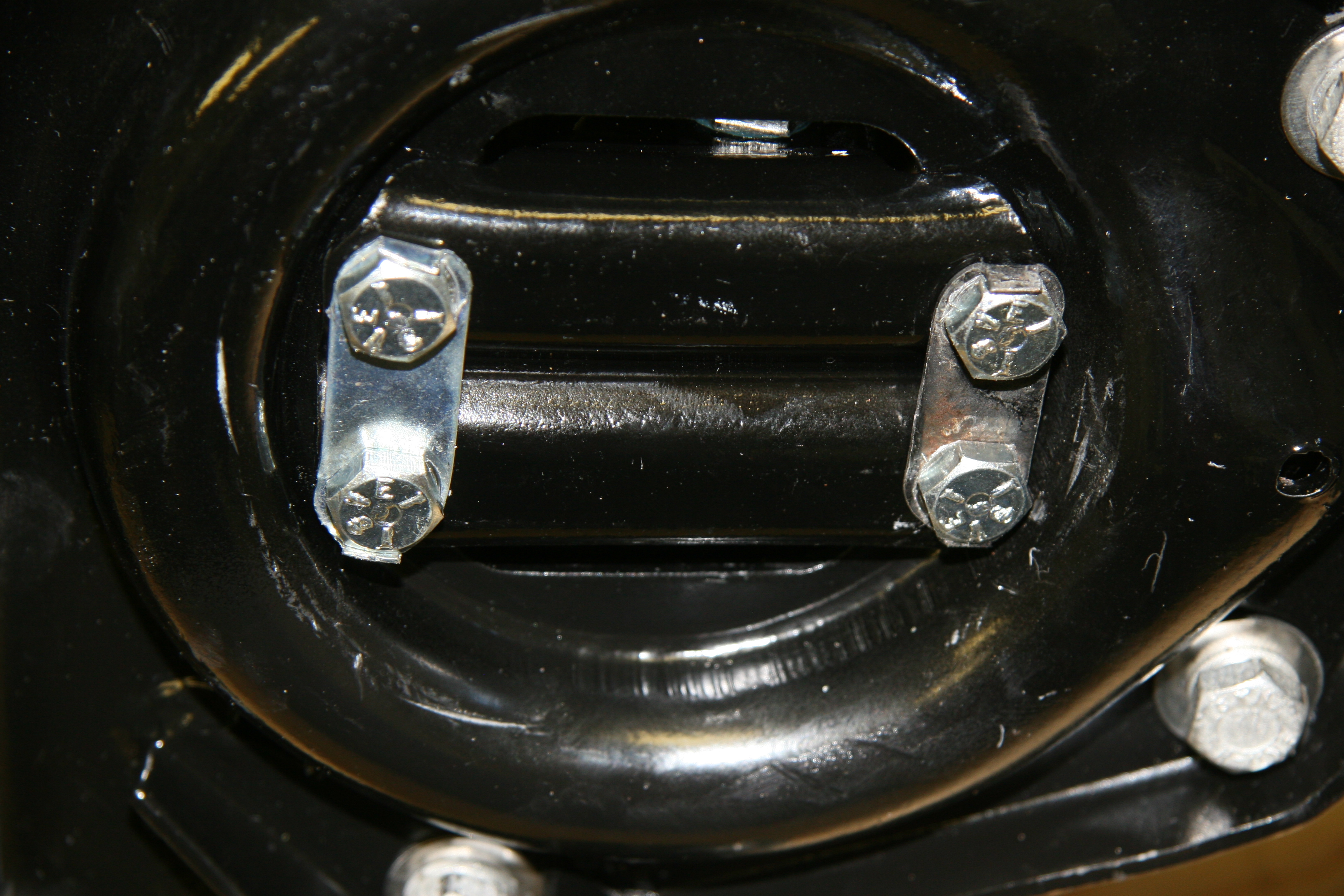
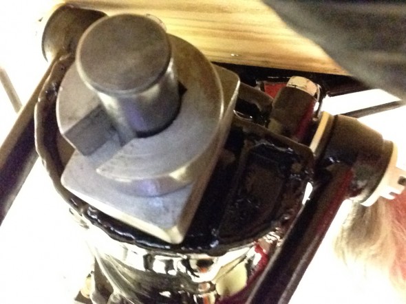
The Service Manual suggests that a fibre packing piece be interposed between the upper wishbone levers and the cross member turret. I’m sure that the design provided in the manual is fine, but after creating a block per the provided description, I felt that it was unstable. Instead I created a different shape block as seen in the image below. To make it work I inverted the rubber bump stops. Once the assembly is on the car, I will knock out the wood block and reconfigure the bump stops in their proper orientation.
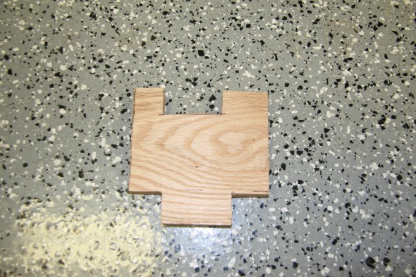
Wood Packing Piece
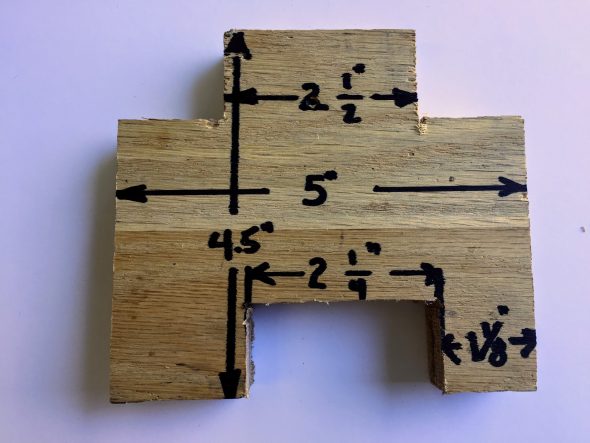
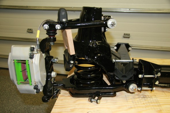
Wood Packing Piece
This image shows both springs installed in the front suspension crossmember. Pleased to have that job behind me!
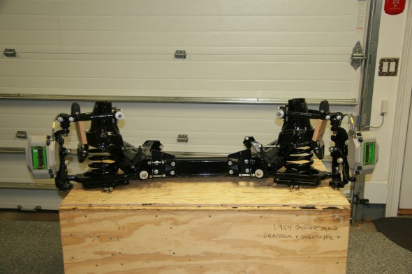
Crossmember Assembly with Springs
While I am not a actor or a video director, I did put a six minute video together demonstrating the installation process:
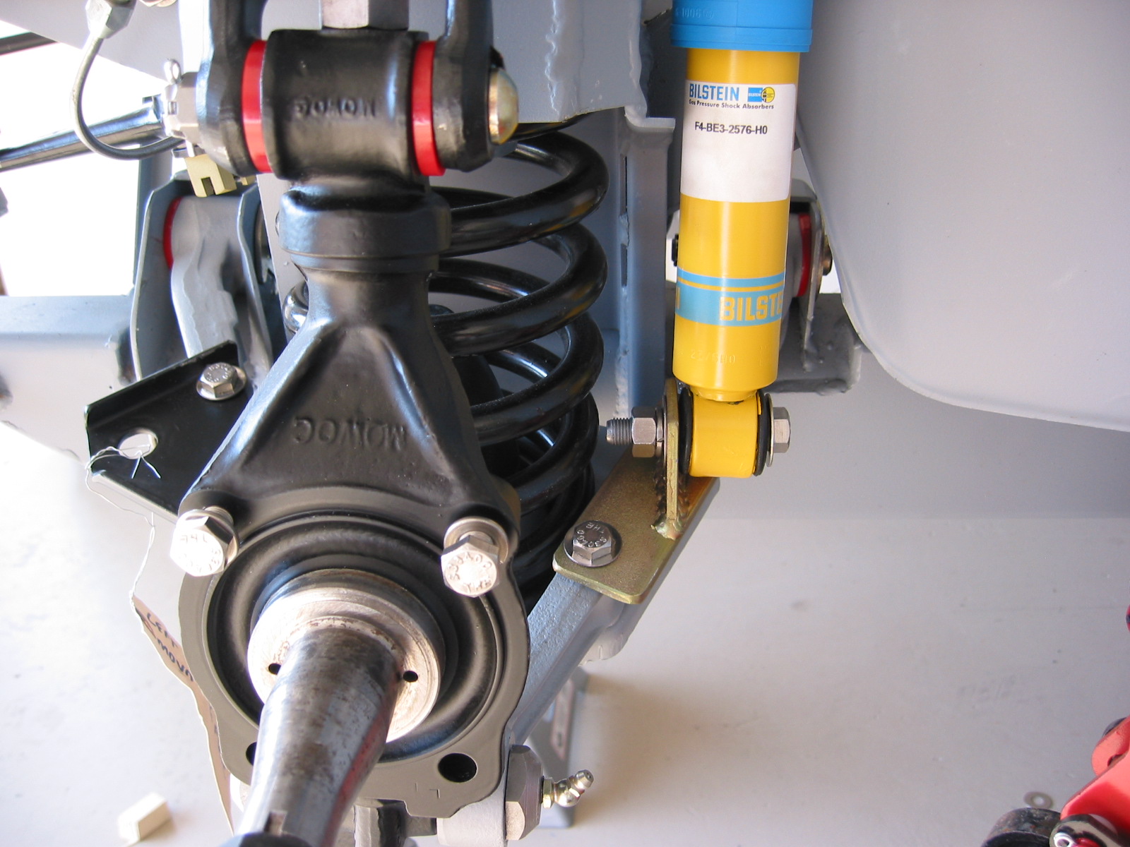
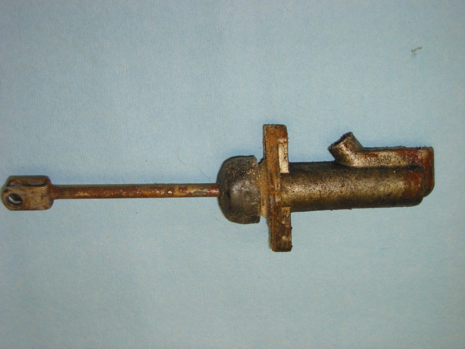
Front Dampers or Shock Absorbers
Mike Eck mikeeck@optonline.net a frequent contributor to the MK2 Forums and email list recommended using shocks available from NAPA in the front of the car. I decided to give them a try. Part number is RR 94012. They are very reasonably priced. The box states that they are a product of Tenneco but I think they are a Monroe shock and they are painted the color of blue usually associated with Monroe. I didn’t care for the blue, so I painted both with gloss black POR-15.
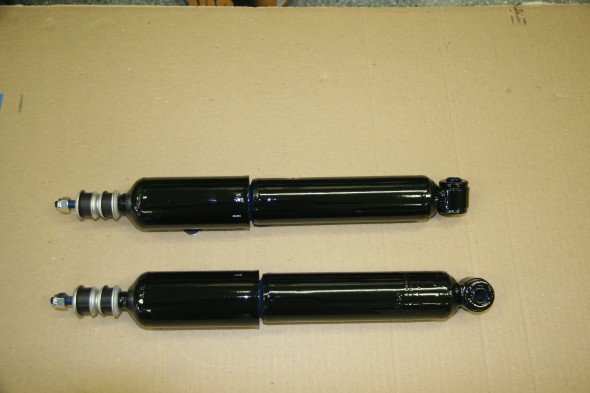
New Front Shocks Painted with POR-15 with Washers and Buffers
Lower Mount : Stem 3/8″ x 24
Shock Compressed Length : 9.875″
Shock Extended Length : 14.375″
Shock Travel Length : 4.5″
Upper Mount : Stem 3/8″ x 16
Shock Dust Shield : Yes
Shock Parts Pack Part # : P1135
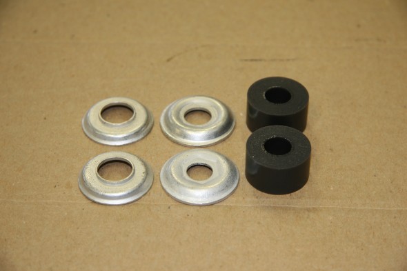
Front Damper Inner and Outer washers with Polybush Buffers
Bracket Under Spring Seat, For Mounting of Front Shock Absorber Installed with Tab Washers Bent
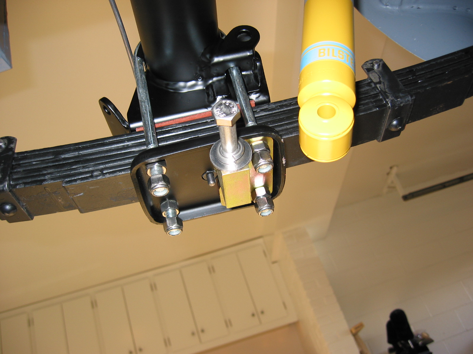
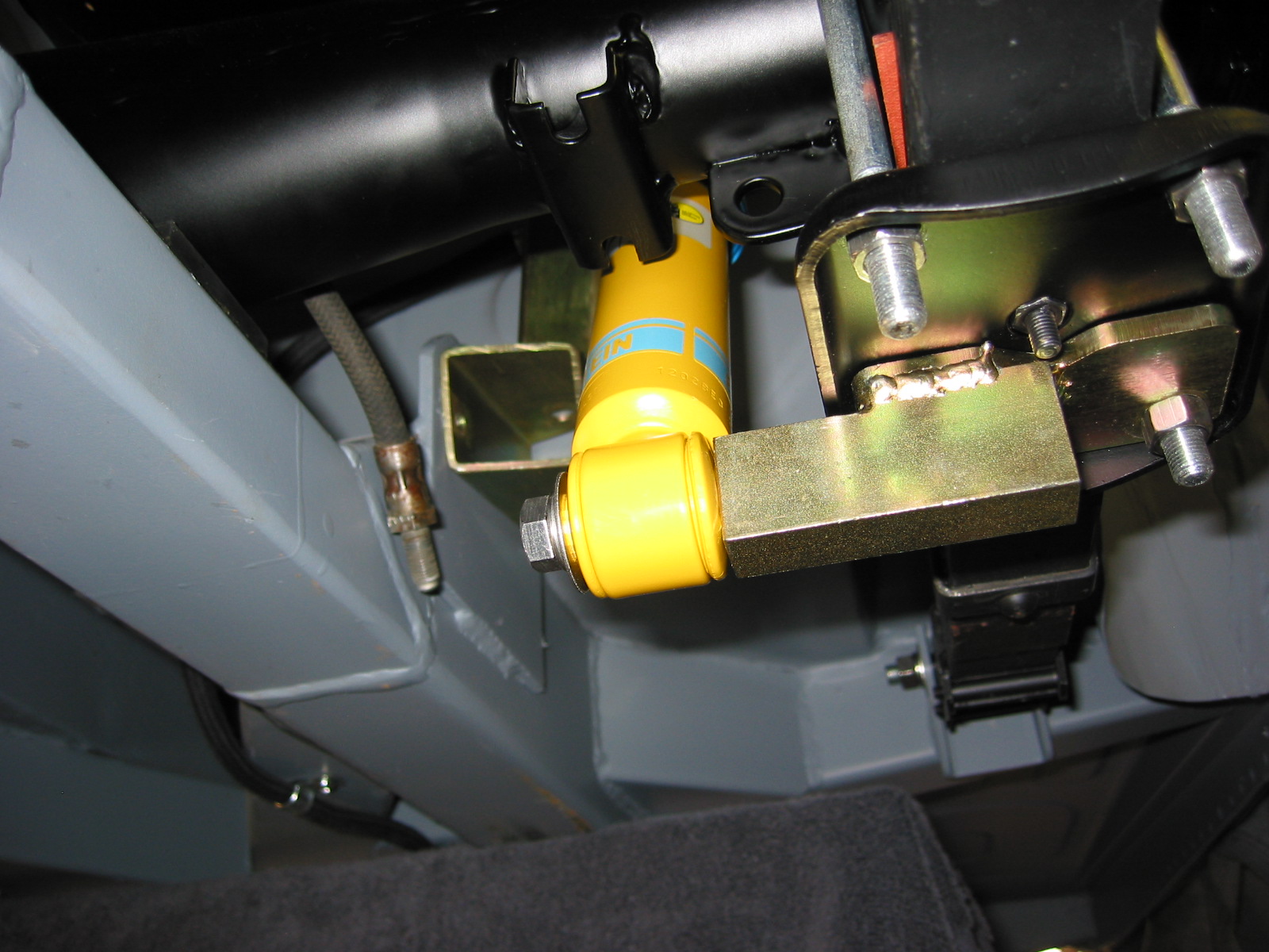
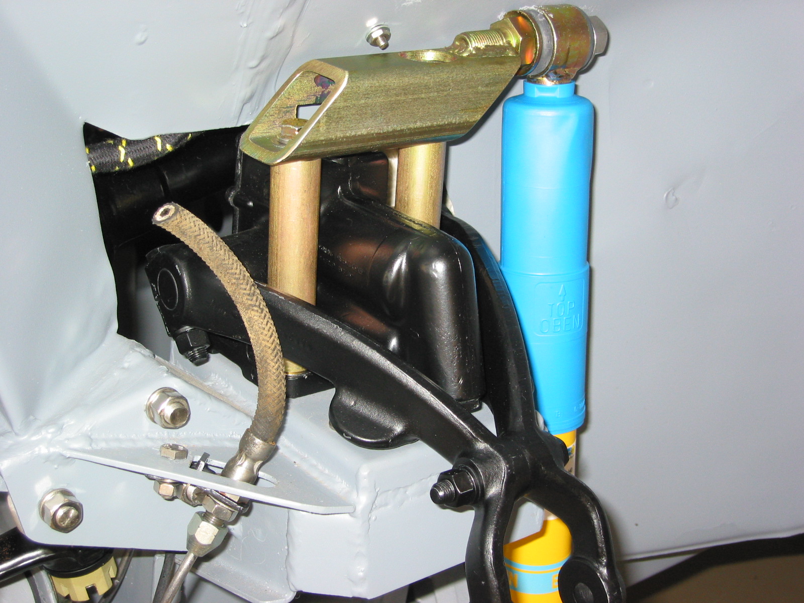
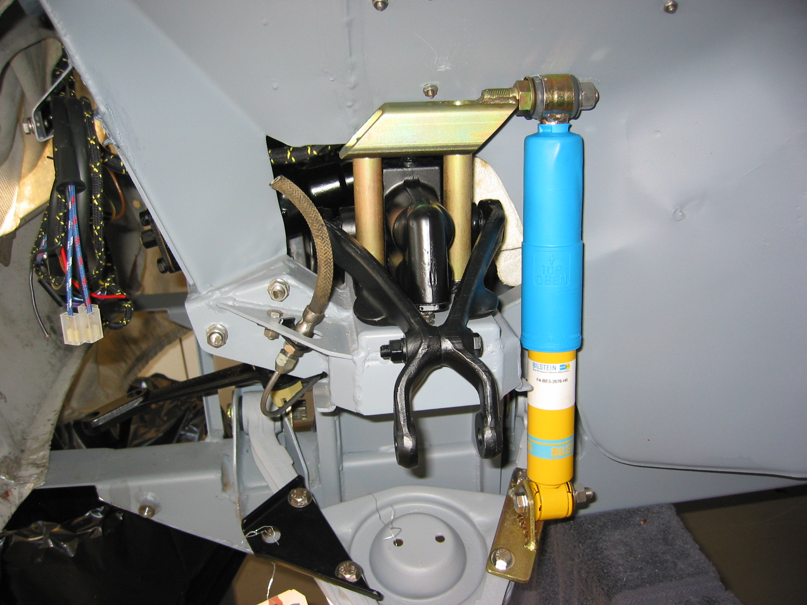
When installing the washers and buffers one must be careful to put them in place in the proper sequence. The inner washers have a shoulder that when properly aligned fit into the turret distance pieces. I used polybush bushes rather than the standard rubber. The manual states, “before fitting a damper to a car, it is advisable to carry out the following procedure to bleed any air from the pressure chamber that may have accumulated to the the damper being stored in an horizontal position. Hold the damper in its normal vertical position with the shroud uppermost and make several short strokes (not extending more than half way) until there is no lost motion and finish by extending the damper to its full length once or twice..”
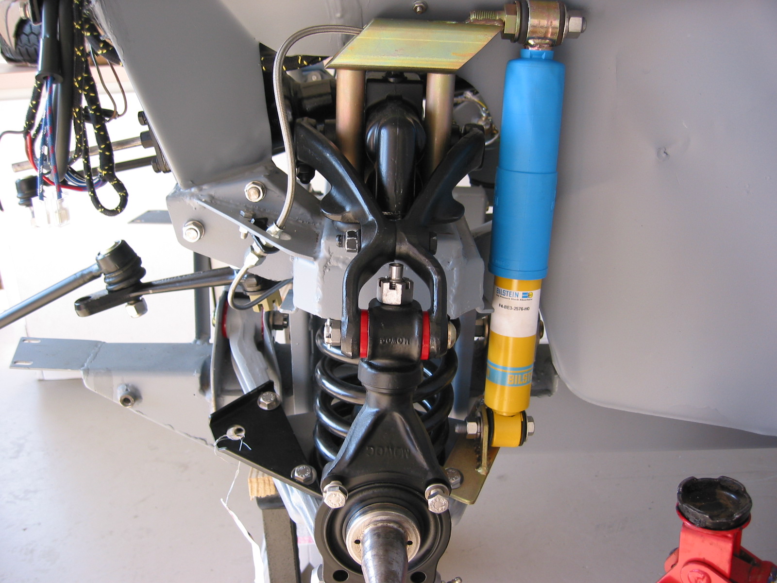
I followed the guidance provided and after inserting one pair of washers and a polybush buffer on the top threaded rod of the shock I positioned it through the coil spring and up through the hole in the turret. I found it easiest to turn the assembly on its side. As referenced earlier there is a LH and RH side to the bracket. On one side the holes for the bolts are closer together than on the other side. This, of course, translates to the shims as well.
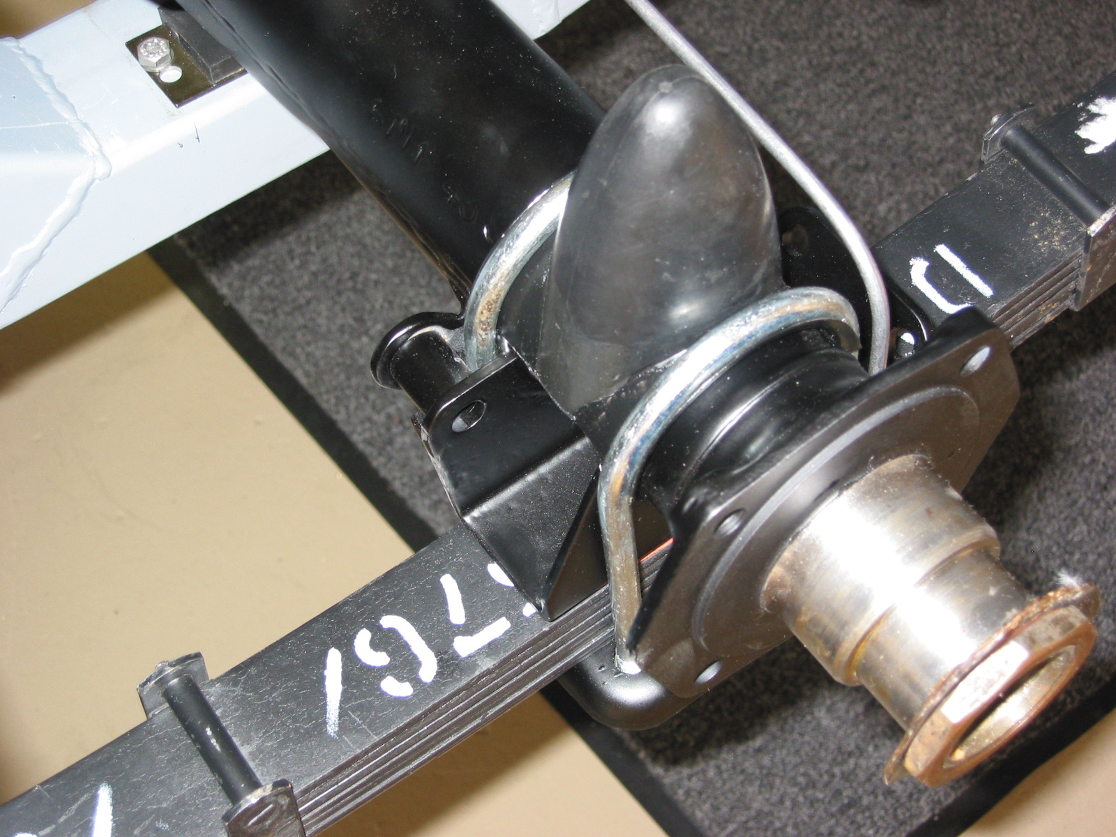
I then turned to the top of the turret, installing the other pair of washers and a polybush buffer and locked it down with 3/8″ – 24 nylock nut.
Tightening Front Shock in Turret
The process was then completed for the other side of the crossmember.
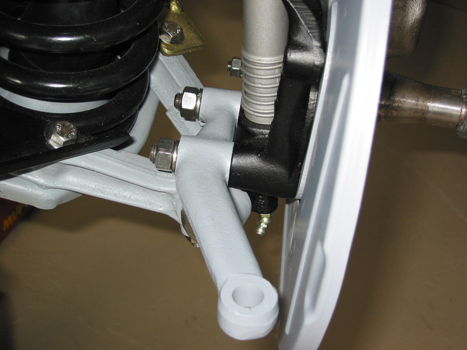
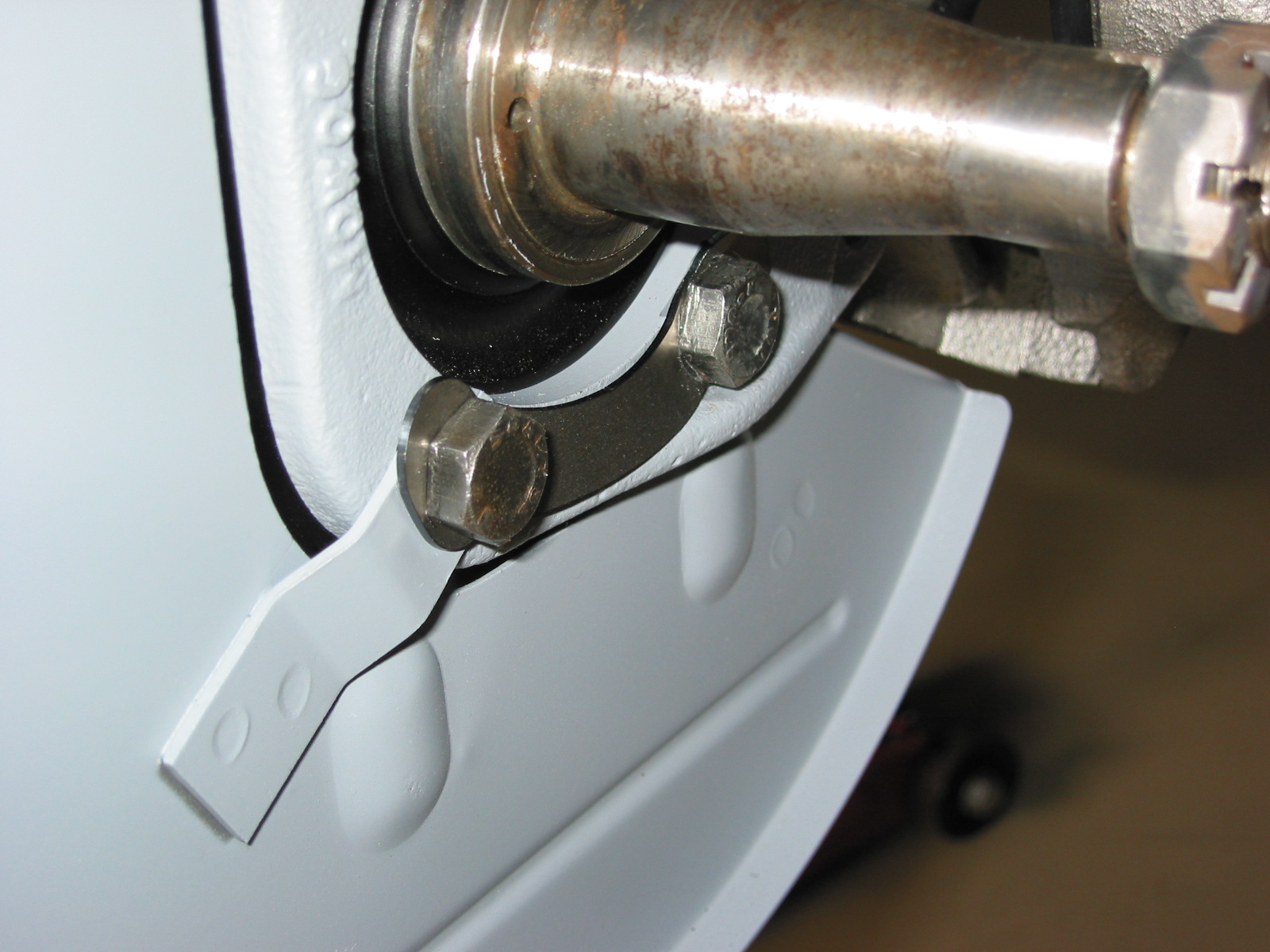
Next, I tightened the bolts on the bottom of the lower ball joints and also bent their locking tab washers.
Ball Joint Cap Installed with Tab Washers Bent
Installing the Front Suspension Crossmember
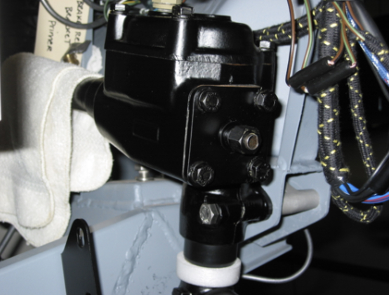
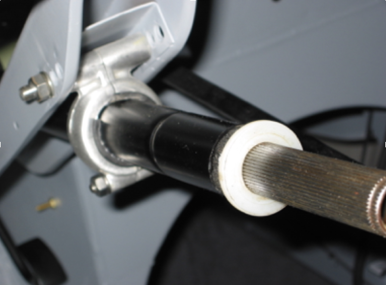
After finding and installing the hose fittings for the steering rack it was time to install the crossmember assembly to the car for a trial fitting. In addition to checking out the fit of the mounts, I needed to fabricate (actually just cutting some steel bar and tube) the new steering linkage connecting the steering rack to the steering column. Unfortunately, this turned about to be a more difficult job than I had expected.
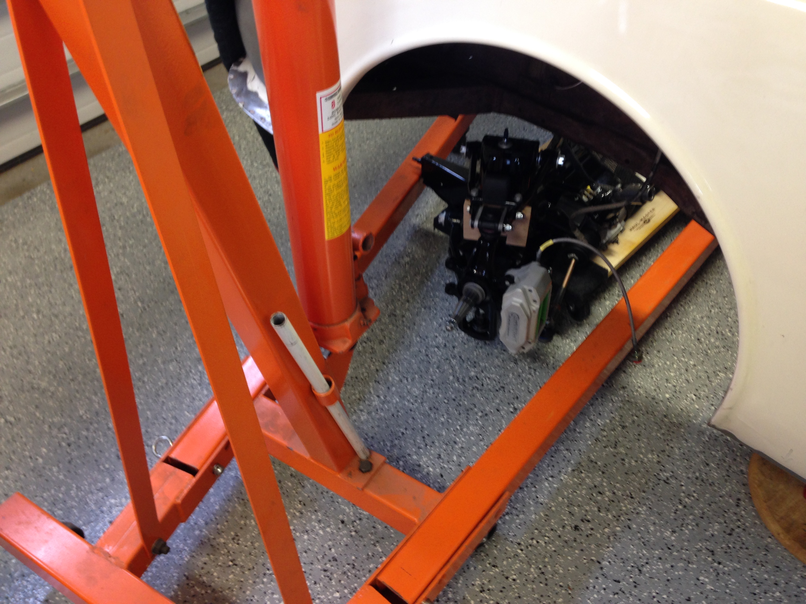
I removed the front dolly from the car and placed the car on jack stands supporting the car at the forward jacking points. After placing the front crossmember on a low-wheeled dolly, I was able to roll the crossmember under the vehicle. I then wrapped a couple of tie-down trailer straps around the crossmember and the steering rack.
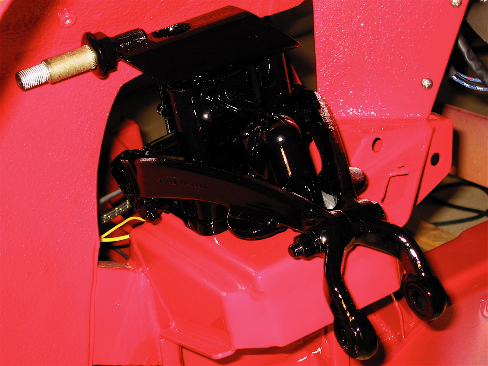
I then moved the engine hoist under the left hand side of the car and after attaching the straps, slowly lifted the crossmember into place. Initially, I made sure that the front mounting studs on the crossmember were located in the proper place and I then used a small floor jack to lift the rear of the crossmember so that the “VEE” brackets lined up with the frame.

Rolling the Crossmember into Place

Using Engine Hoist to Lift Crossmember
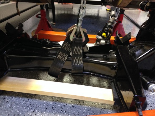
Lifting Straps
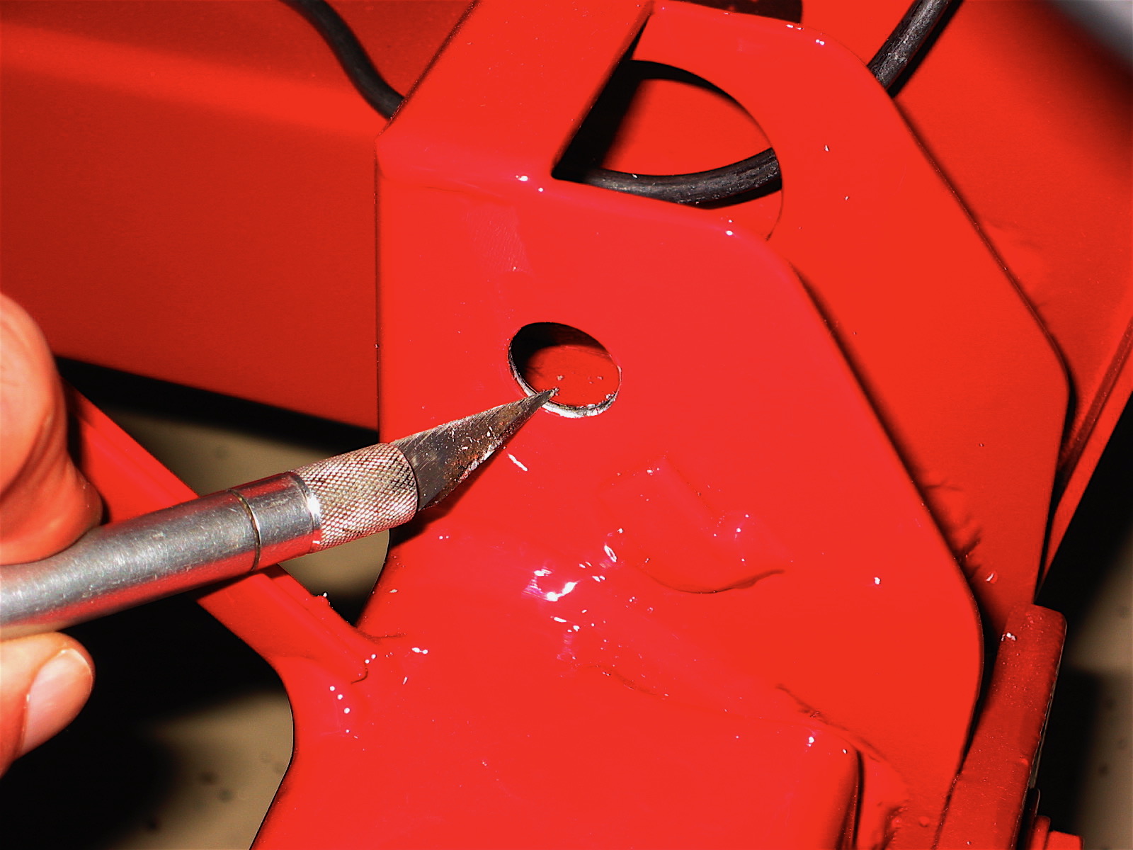
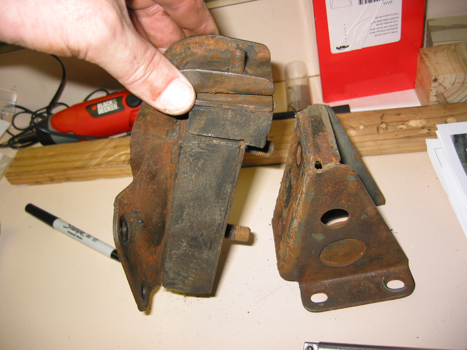
The trouble that I encountered was with the fit of the “VEE” mounts. Neither mount lined up perfectly with the hole in the frame through which a bolt is inserted. After some fiddling I was able to get the RH mount to align but the LH was impossible. I estimated about 1/8″ off center. I finally used a grinder and removed some metal on the inside of the “VEE.” This allowed me to ultimately get a bolt through the mount and the frame although the fit was clearly not proper.
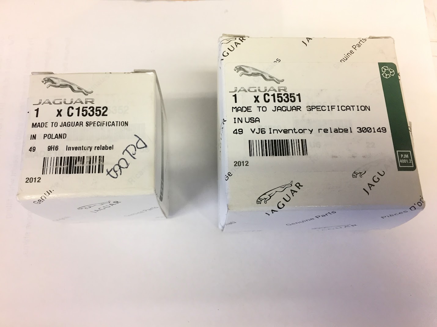
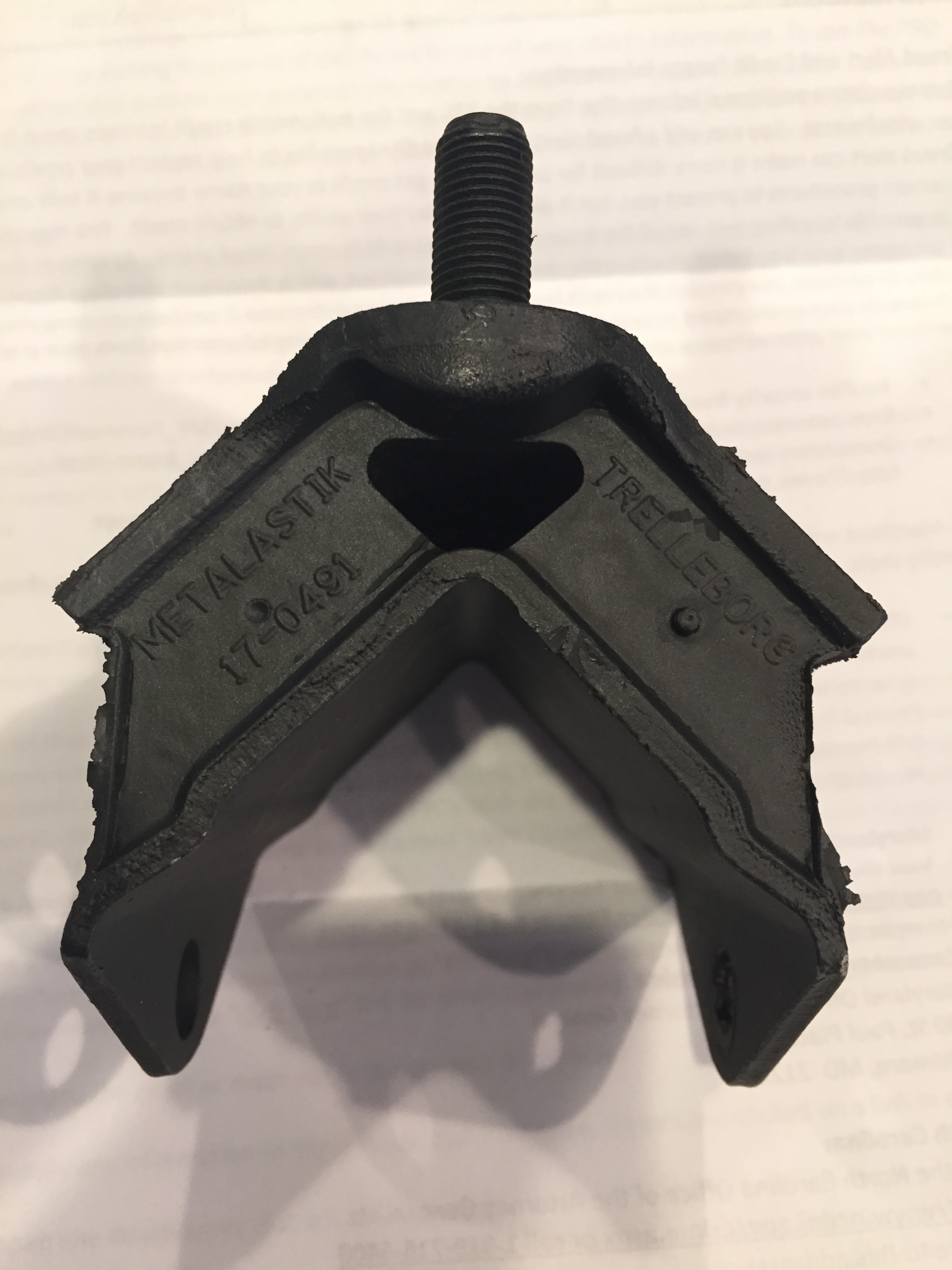
I checked my part order and discovered that the “VEE” mounts had come from SNG Barratt. Upon closer examination I determined that SNG Barratt sells two varieties of the “VEE” mount. The lower price variant was $31.17 at the time of order, and the higher price version was $73.55 when I checked. Sure enough, I had ordered the less expensive option. I called SNG Barratt and enquired about the difference between the two and was told that the more expensive mount was a “precision” piece. I ordered the “precision” mounts and replaced the ill fitting items and sure enough the definition of “precision” is that the parts fit! Very frustrating! Why would you sell something that does not fit – or at least not without modification.
The new mounts are visually much the same but obviously have slight differences in manufacturing tolerances that produced better results. The more expensive mount does have a “Metalastik” and “Trelleborg” manufacturing imprint apparently indicating a quality piece. Metalastik and a branch of Trelleborg merged to produce rubber/metal bonded products.
http://tinyurl.com/hoyl6qe

Metalastik Telleborg “V” Mount
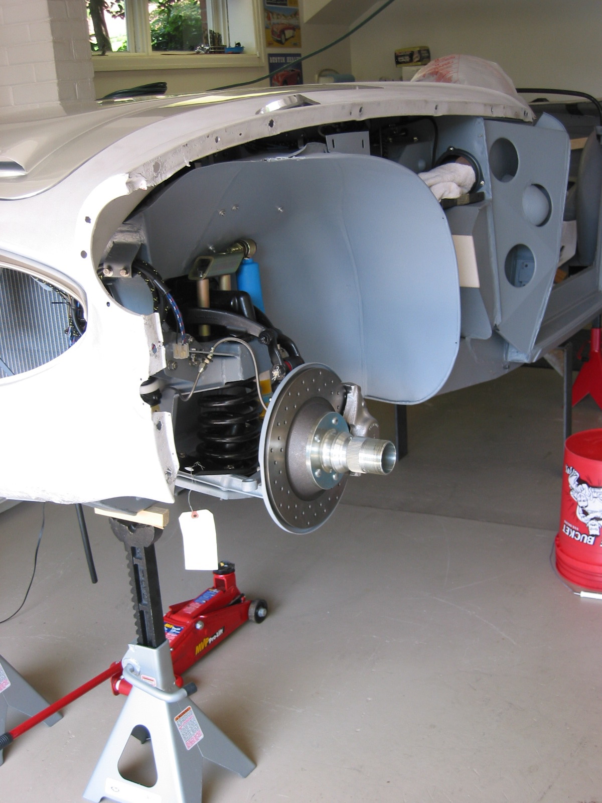
Having checked the “fit” of the front cross member assembly on the car, I removed it and prepared to install the front hubs with brake rotors to the stub axles. Of course, this required the removal of the calipers. I had previously installed the inner and outer bearing races in the hubs.
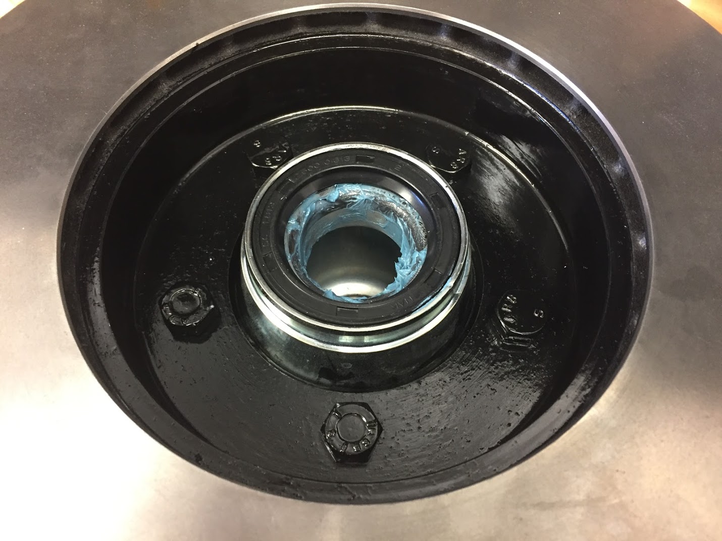
It was now time to “pack” the bearings with high temperature bearing grease. I like to do this by hand and press the grease through one side of the bearing until I see the grease begin to extrude through the other side of the bearing. I then liberally coat all surfaces of the bearing with grease. The inner bearing is installed in the hub while on the bench. It is lightly pressed into place and the rubber seal with the cupped side and exposed spring wire facing toward the bearing is then tapped into position. The image below shows the inner bearing in seal installed in the hub.

Packed Inner Bearing Installed in Hub with Seal
I coat all surfaces with a light smear of grease. The maintenance section of the Service Manual states: “do NOT pack the hub with grease but apply a coating to the inside of the hub between the outer races of bearings. Apply a light coat of grease to the stub axle shaft; do not fill the hub end cap.” The hub and rotor are then offered up to the stub axle and the outer bearing is slipped on the stub axle against its race.
Packed Outer Bearing Installed
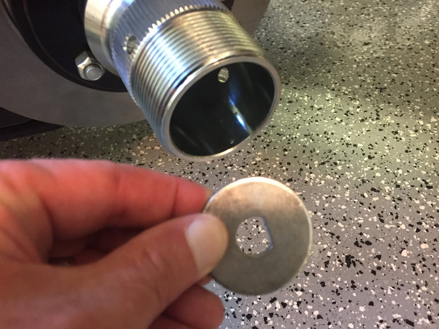
Then a special “D” washer is pressed in place over the stub axle end.

Stub Axle Special “D” Washer
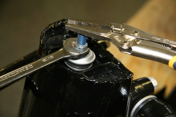
Then a 1/2″-20 castle nut is threaded onto the stub axle.
The Service Manual states, “Tighten the hub nut until there is no end-float, that is when rotation of the hub feels slightly “sticky”. Slacken back the hub nut between one and two flats depending on the position of the split pin hole relative to the slots in the nut.
Temporarily attach the road wheel and check that the wheel spins freely. If satisfactory, fit a new split pin and turn over the ends.”
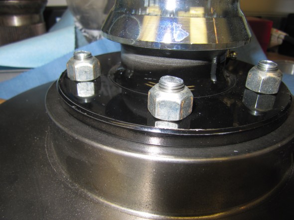
I used a torque wrench to tighten the nut to 45 pounds and then backed off the nut as described. The hole in the hub was then aligned with a notch in the castle nut and a hole in the stub axle end permitting the installation of a 1-1/2″” split pin.
Castle Nut Installed and Aligned
Split Pin Inserted Through Castle Nut and Stub Axle Hole
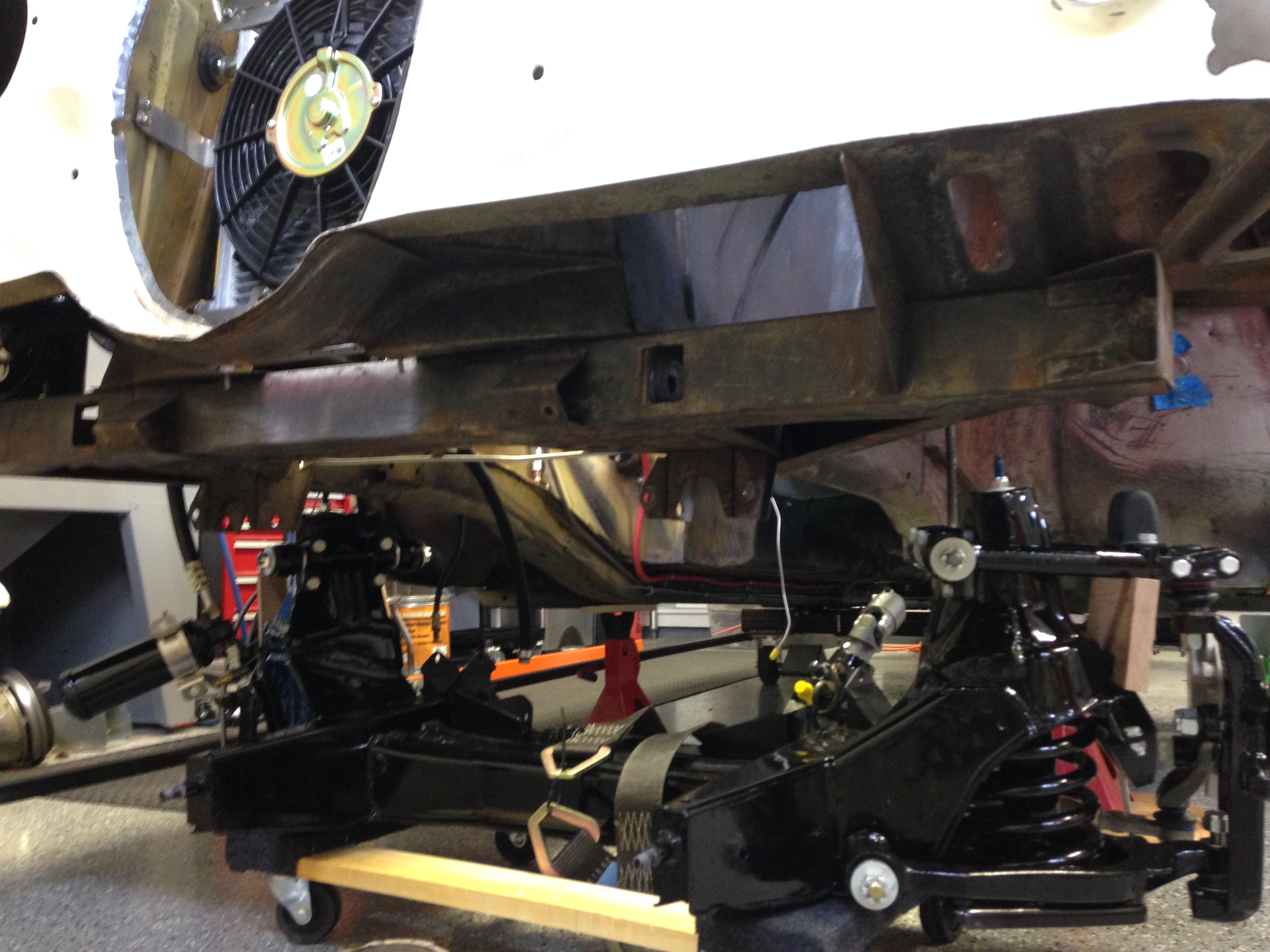
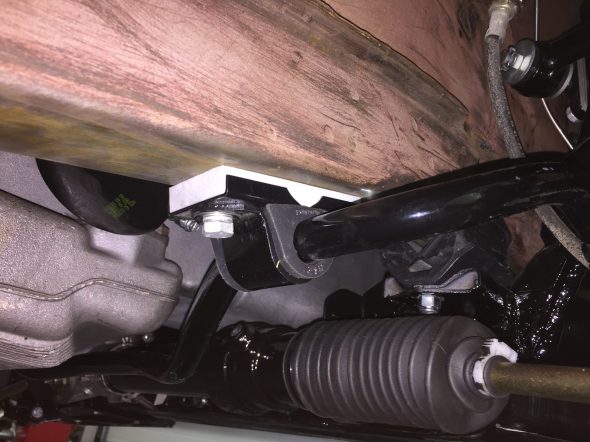
It is May of 2017 and I am ready to install the front suspension crossmember assembly on the car AGAIN. This time it will be to actually test drive the car. Then, as I have said previously, I will strip the car for paint. At least when I reinstall the front suspension this time I know I will be doing so with rear mounting brackets that will actually fit!
First, I loosened the two nylock nuts on each of the rear “V” bracket studs so there would be some slack in the mounts as they mated with the chassis frame rails. I then centered the cross member with hubs, brake rotors, calipers installed but without the steering rack, on my floor jack and slid it under the car (the car was already on jack stands). I roughly positioned it in place and lifted it until the front mount studs aligned in the front chassis mounts. However, I did not fasten the front mounts at this time. I then continued to raise the crossmember until the rear “V” brackets aligned with the mounting holes in the chassis frame rails.
I inserted the LH rear “V” mount bolt through the mount and the frame rail and loosely fitted a nylock nut on the inside (engine bay side) of the bracket. I then repeated this procedure for the RH side of the car.
I then secured the front mounts with the two bolts per side and tightened them in place. The rear “V” mount bolts that go through the frame rails were then securely tightened, and lastly the two nylock nuts at the bottom of each “V” mount were tightened. That completed the installation of the crossmember.
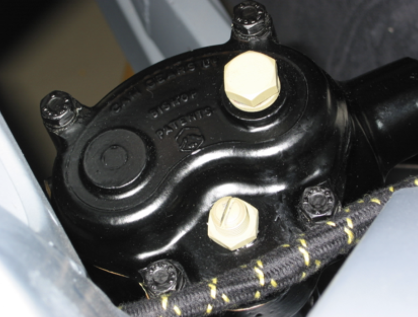
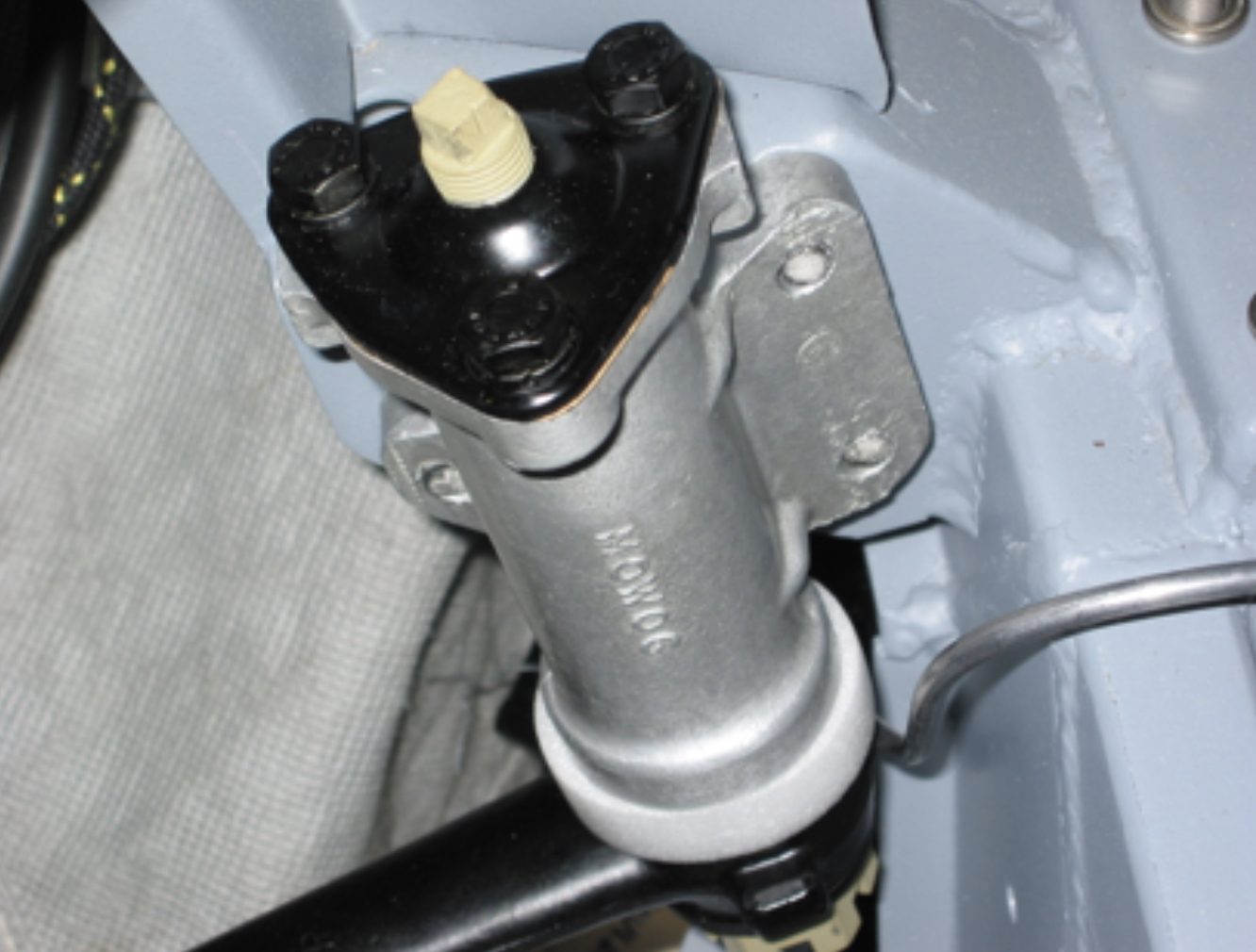
Next came the installation of the rack and pinion steering rack to its brackets that were already mounted on the front suspension cross member. One bolt inserted on the RH side and two on the LH side. All three then tightened. More detail is provided in the “Steering” entry to the website.
I then proceeded to mount the anti-sway bar to the front suspension cross member assembly. The first step was to assemble and mount the anti-sway bar links with new polybush bushings to the brackets on the lower coil spring seats. Details about the links are provided earlier in this post. This photo shows the links mounted to the coil spring seat and to the anti-sway bar.
Anti-Sway Bar Link Mounted
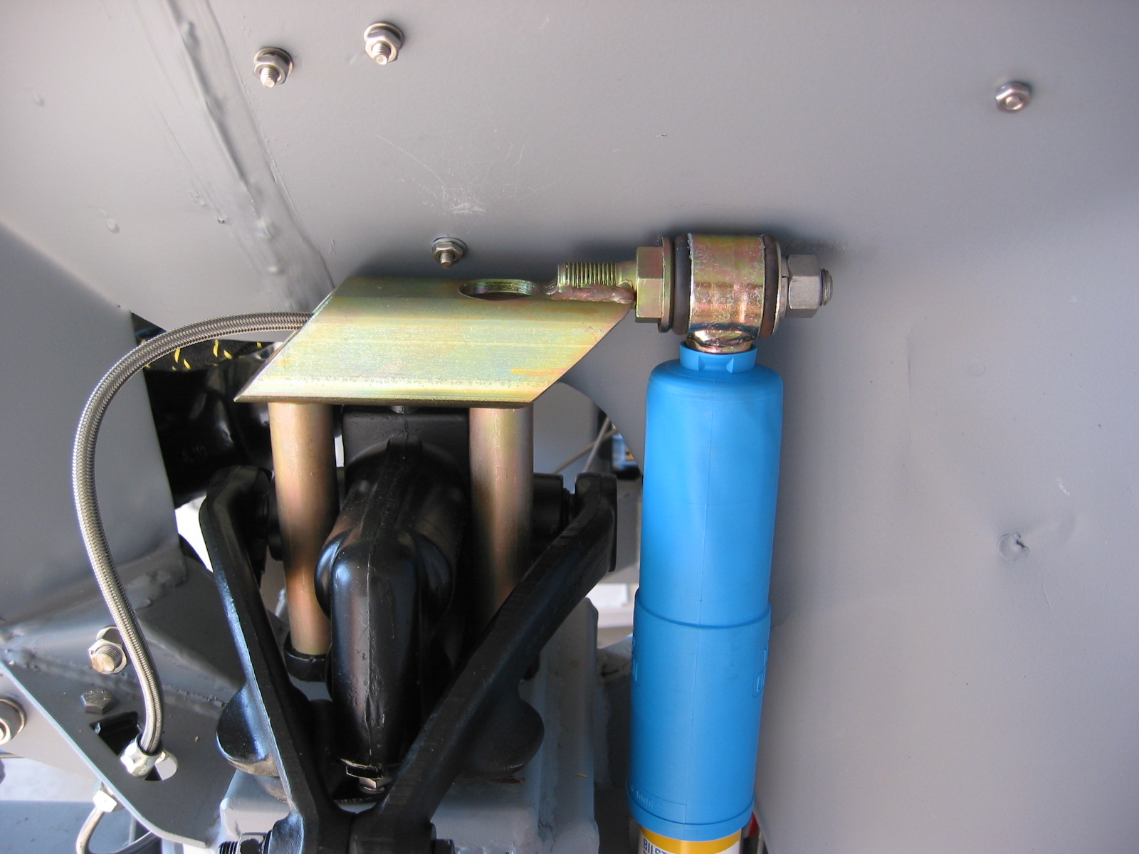
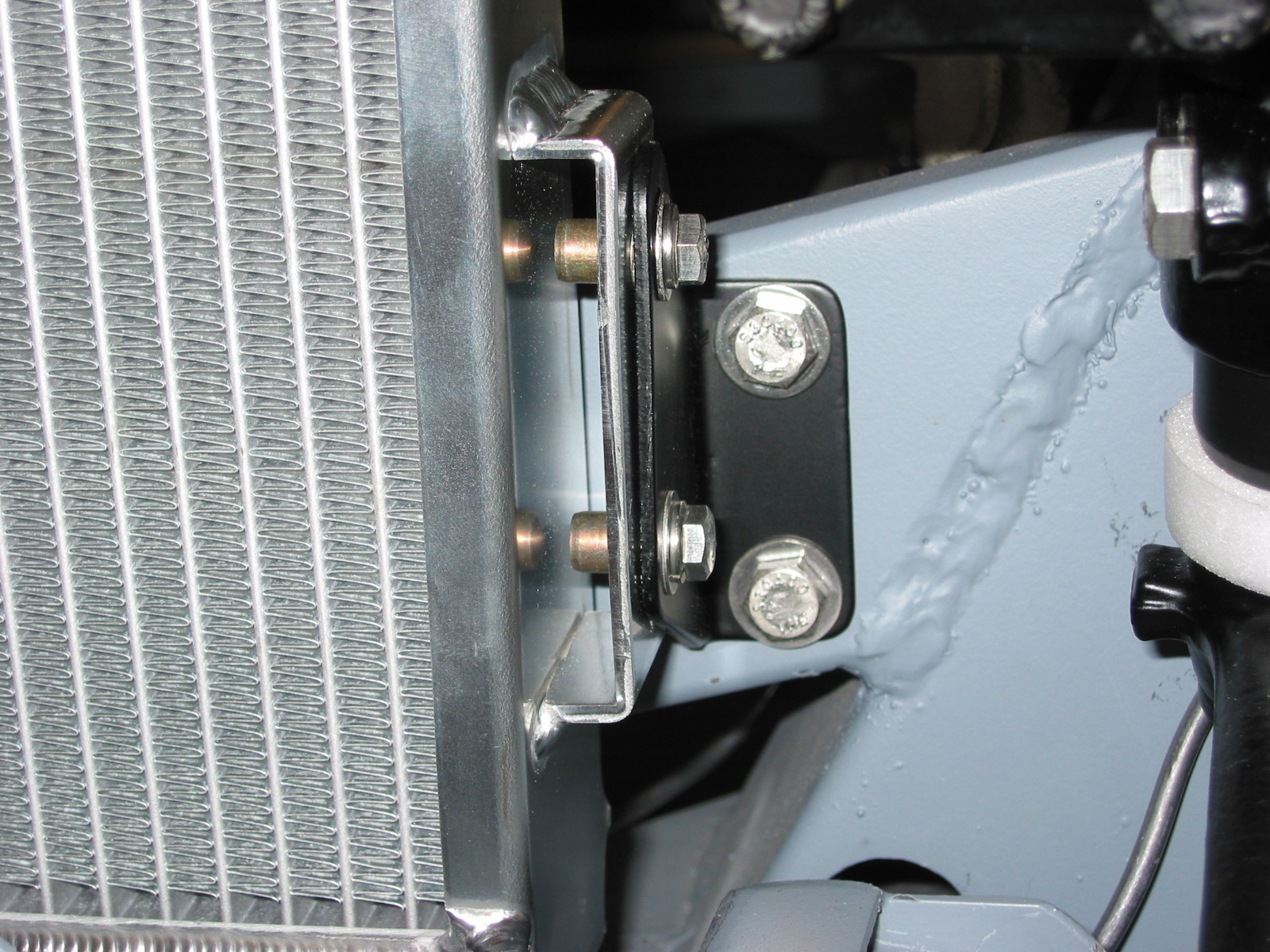
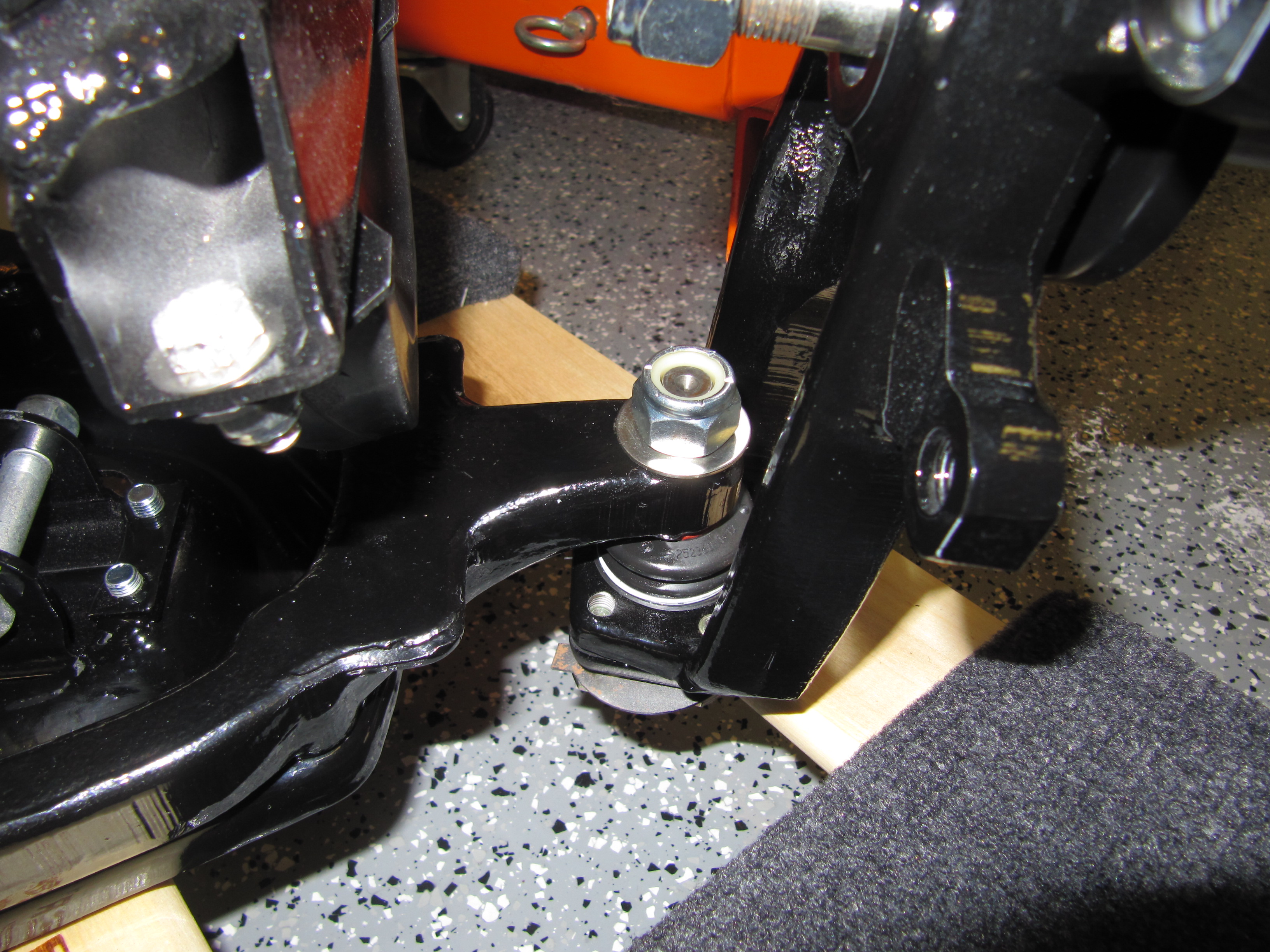
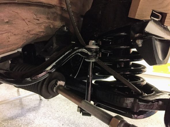
I then lifted the Anti-Sway Bar into place and loosely mounted its ends to the anti-sway bar links. This gets the anti-sway bar into position so that one can then mount the LH and RH aluminum spacers and the sway bar brackets to the frame, each with two hex head bolts. Details provided earlier in the post. I then firmly tightened the chassis bracket bolts as well as the anti-sway bar links.
Anti-Sway Bar Chassis Mounting with Polybush Bushings and Aluminum Spacer Blocks
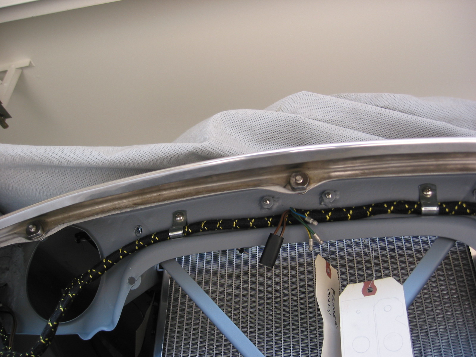
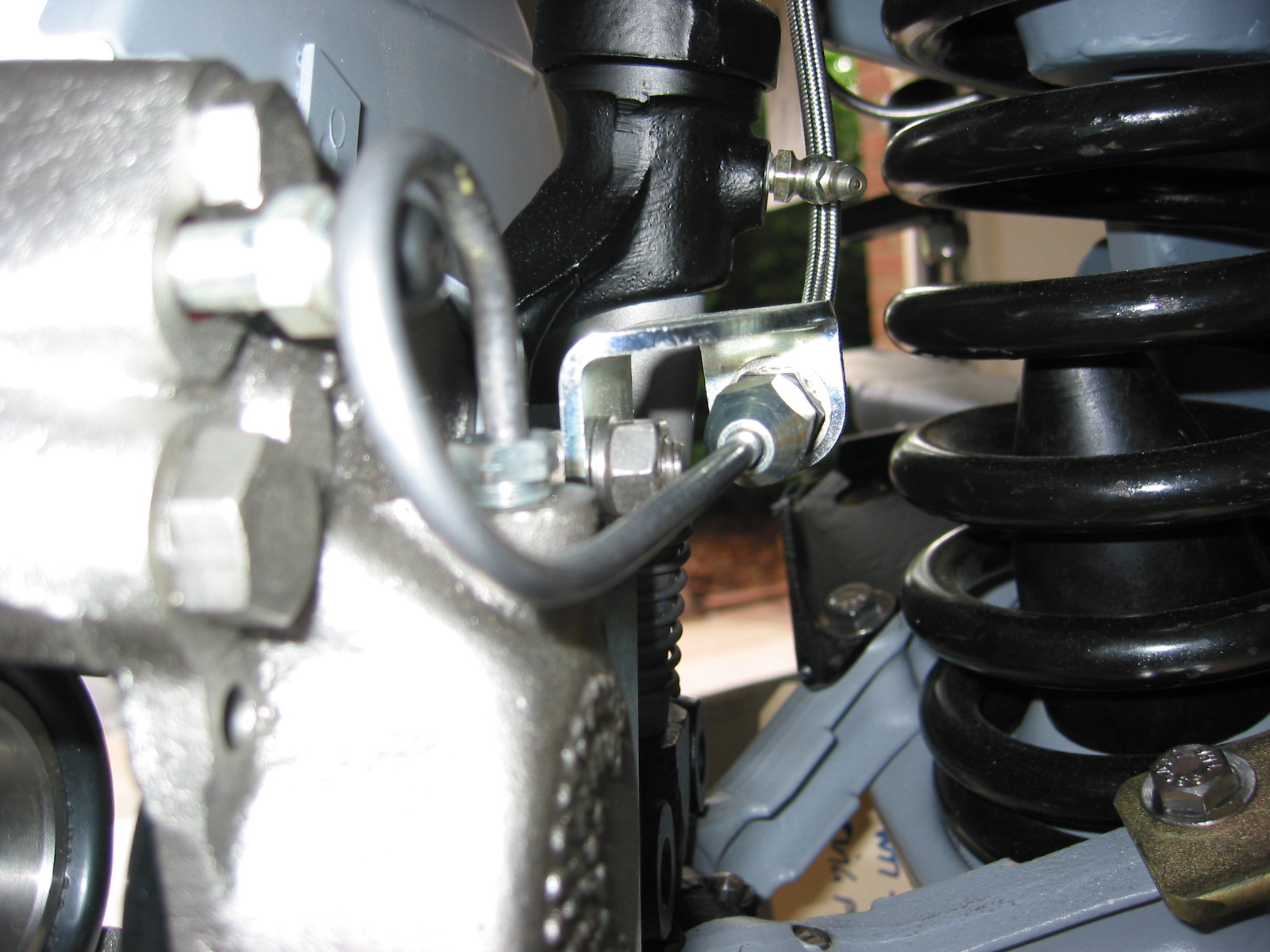
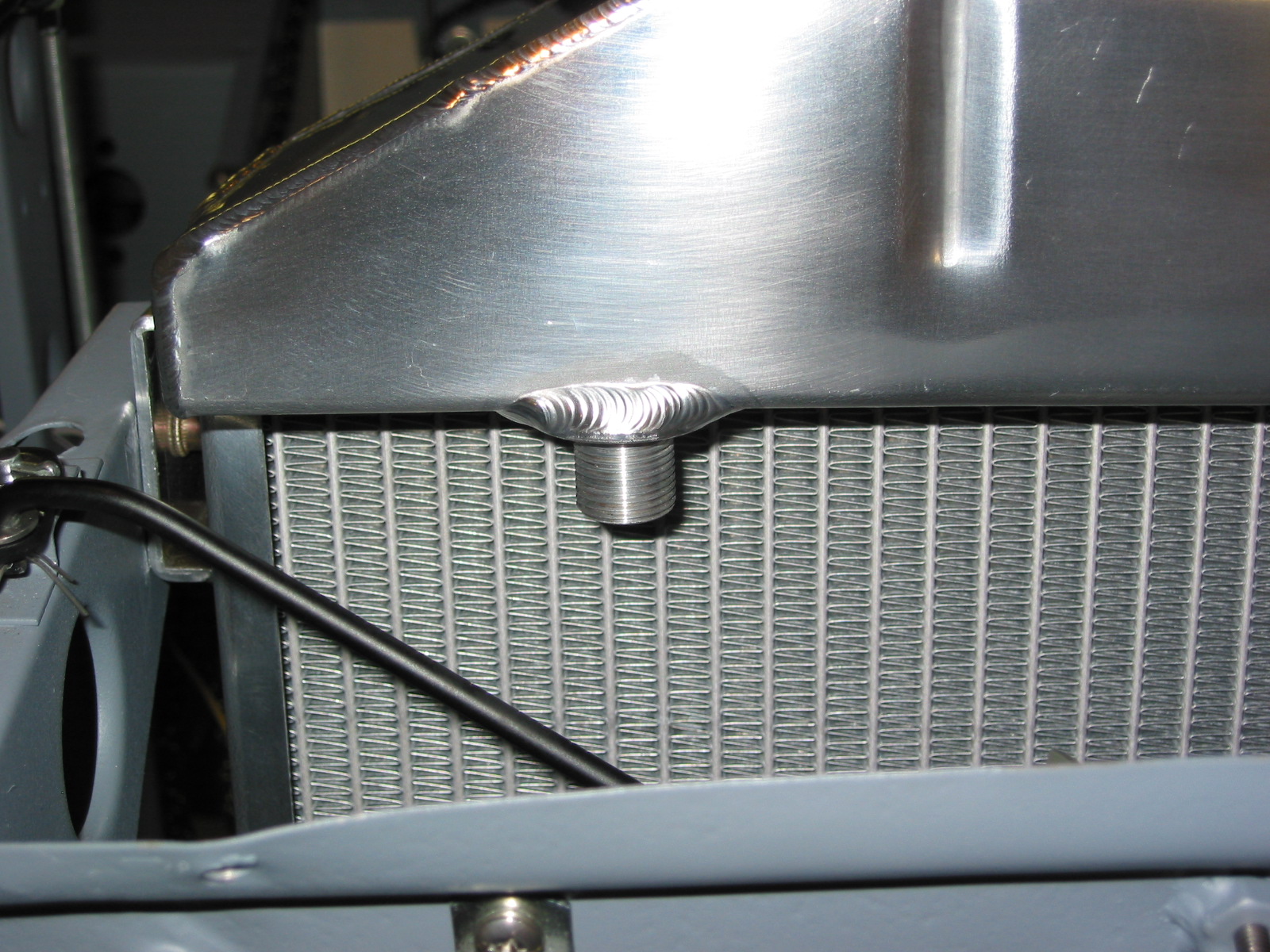
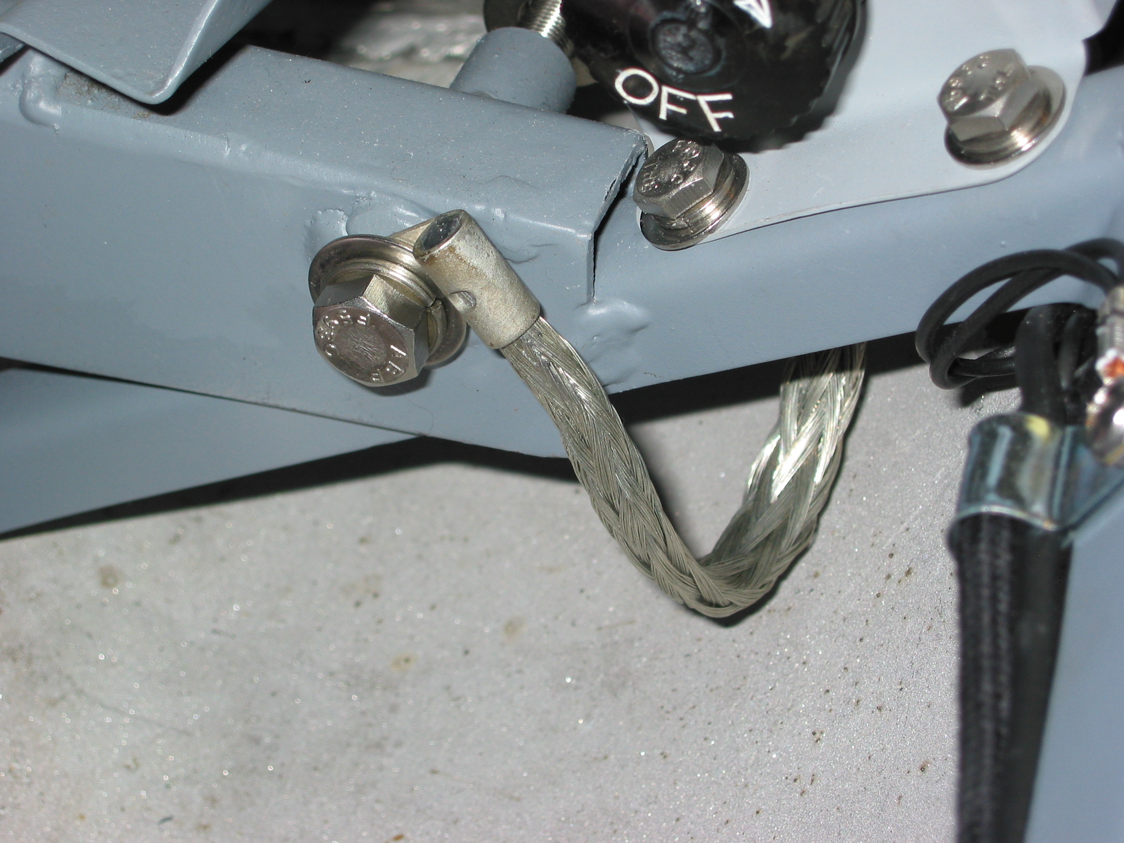
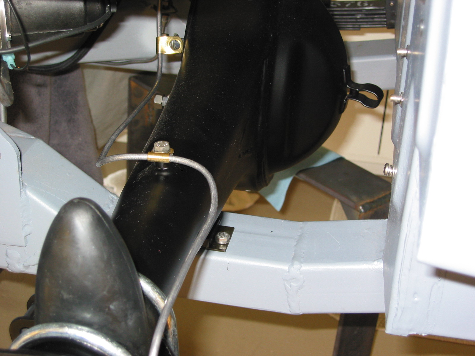
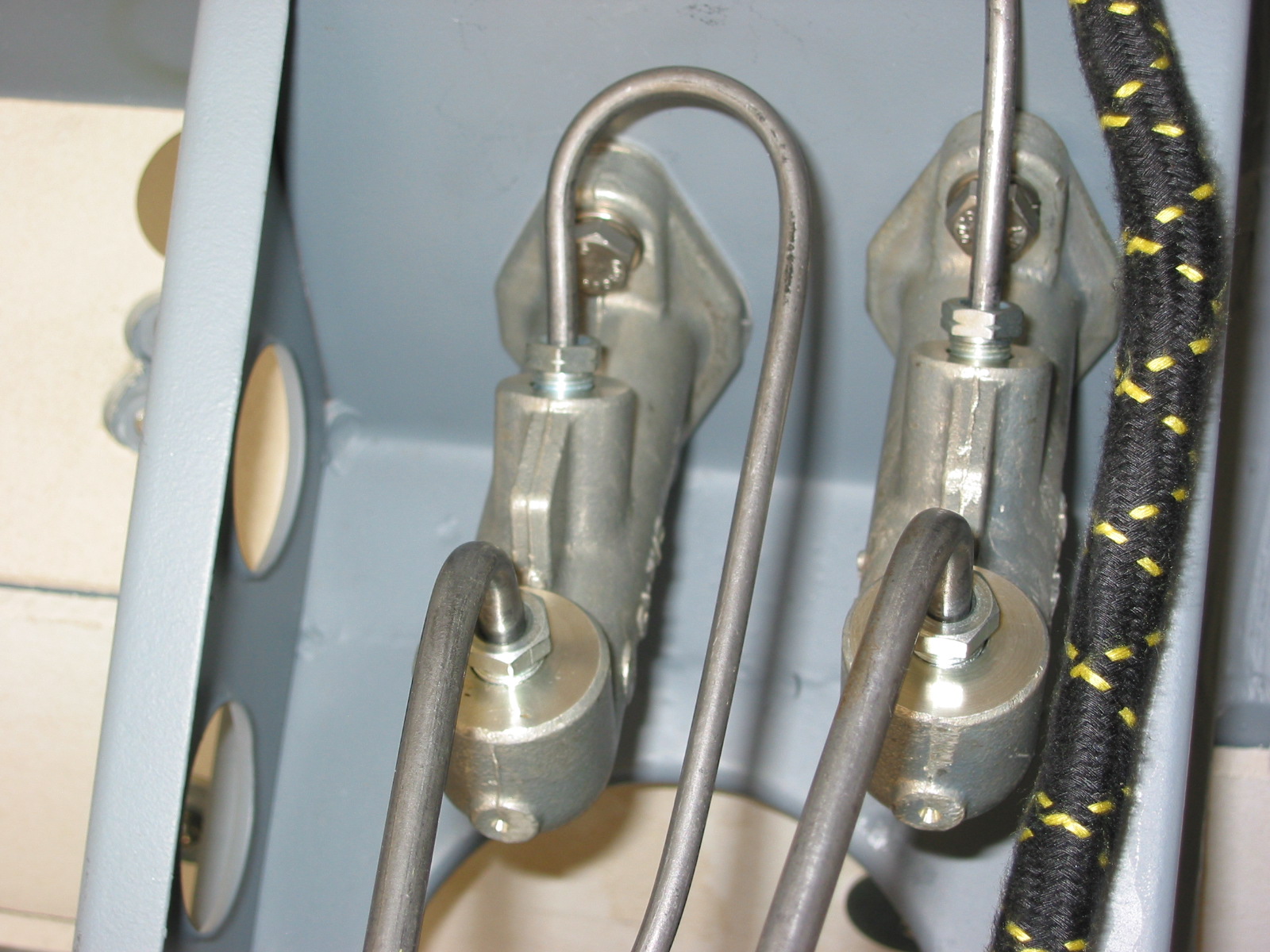
The Goodridge Stainless Flexible Brake Hoses were the next items to complete. These were already connected to the LH and RH calipers. The ends of the hoses are positioned through the welded mounting clips on the inside of each wheel well where they are tighten down and then connected to the hard brake pipes. I found it easiest to connect the hose to the brake pipes first and to then tighten the hose to its mount on the car.
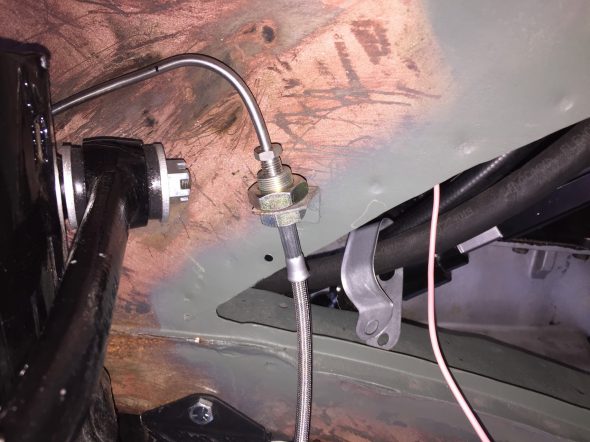
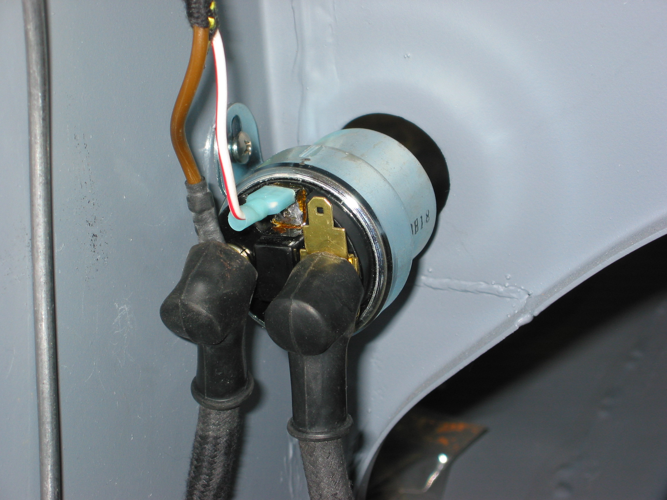
LH Front brake hydraulic line junction to caliper