RH Front Suspension Removal

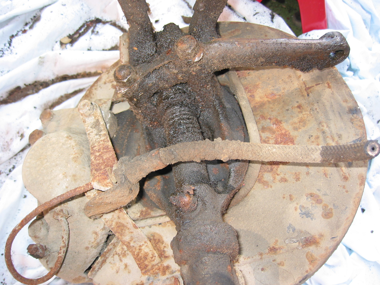
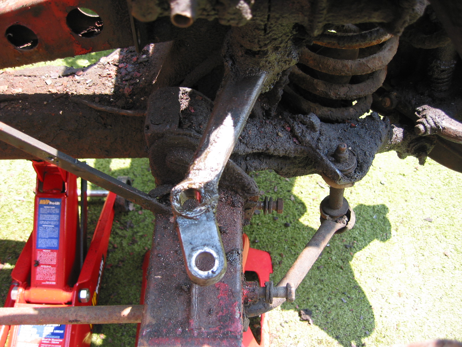
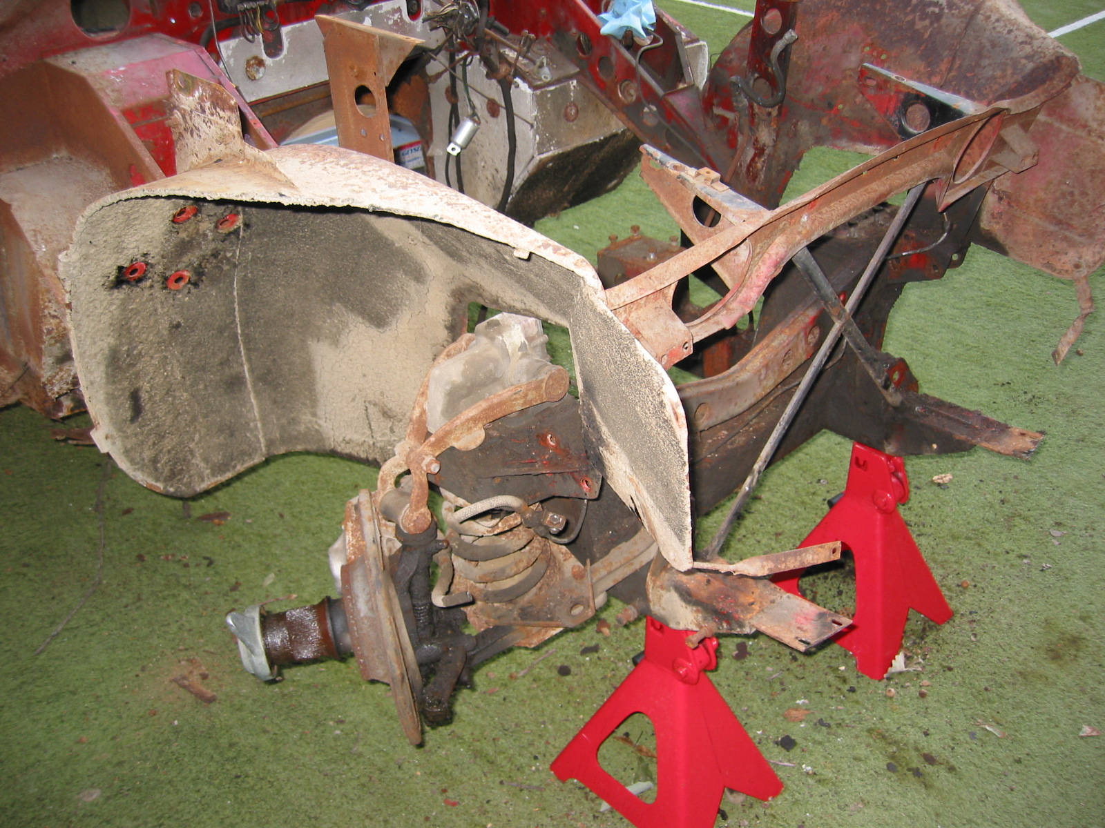
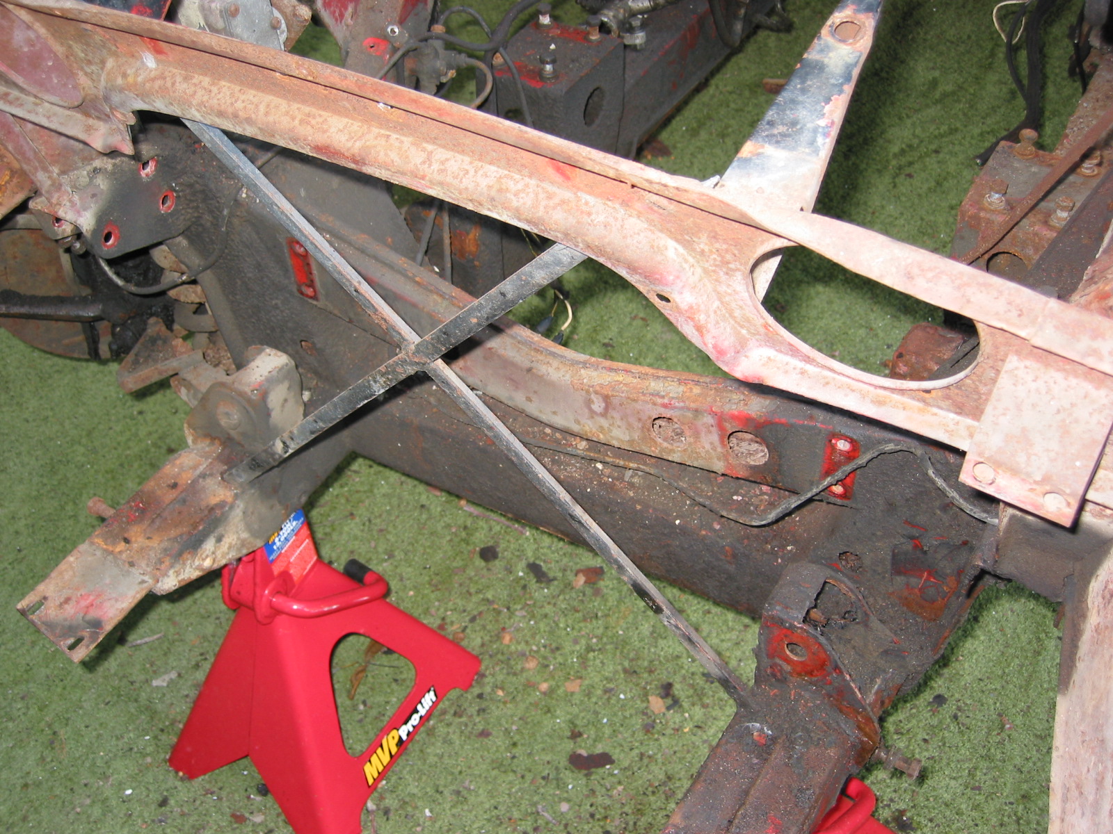
Having completed the work on the refurbishment of the rear axle and suspension it is now time to turn to the front suspension. Our plan will be to remove and refresh or replace the suspension components on the right side of the car, then after building back the passenger side of the car we will go through the same process on the LH side. My car was converted to front disc brakes shortly after we purchased it around 1999.

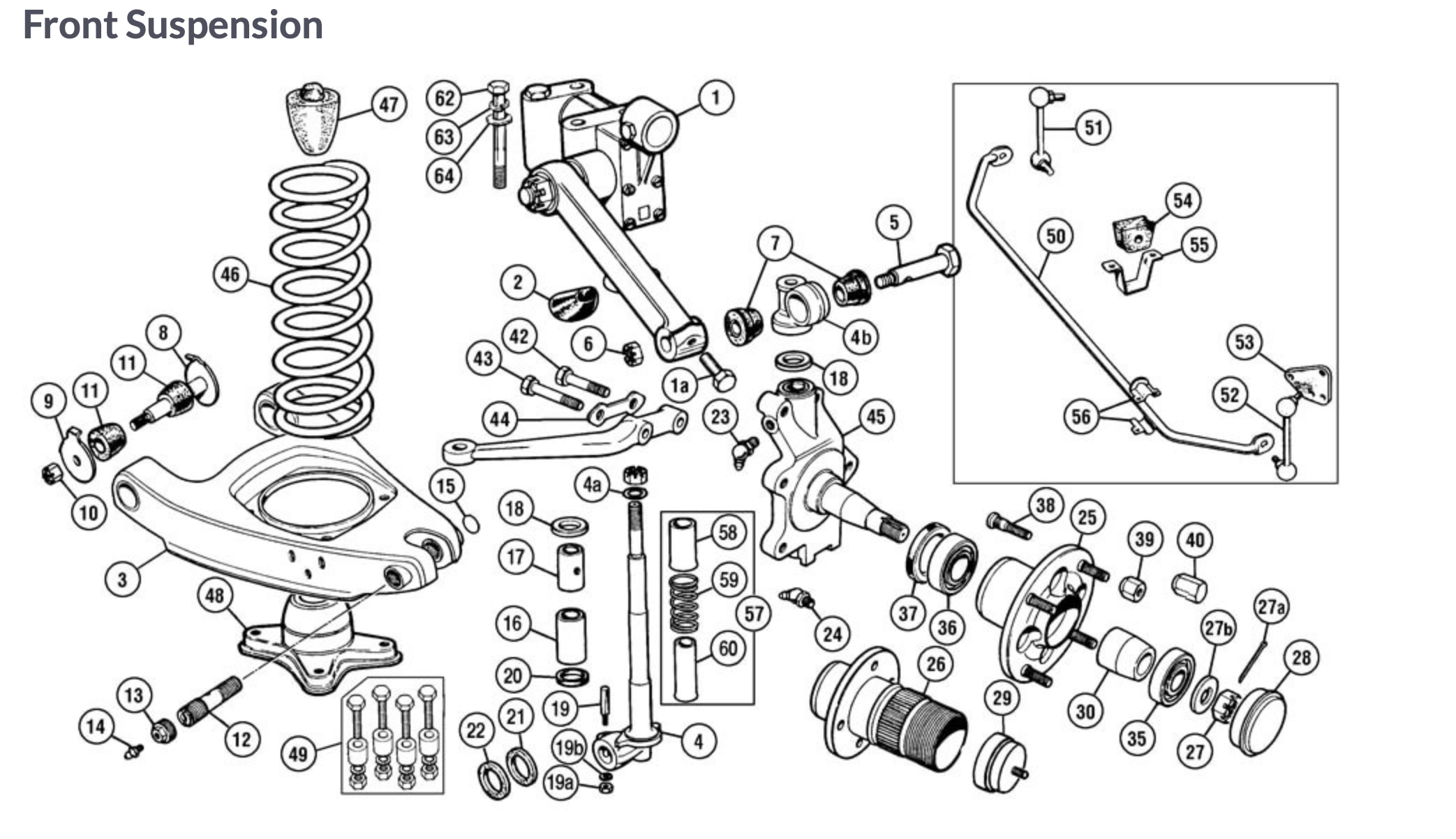
Bugeye Front Suspension Components


https://vimeo.com/777904083/768f53fb47

The Episode Twenty-seven video shows the deconstruction and removal of the RH front suspension. The following steps are addressed in the video:

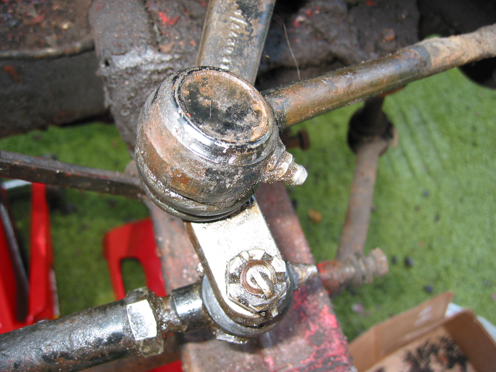
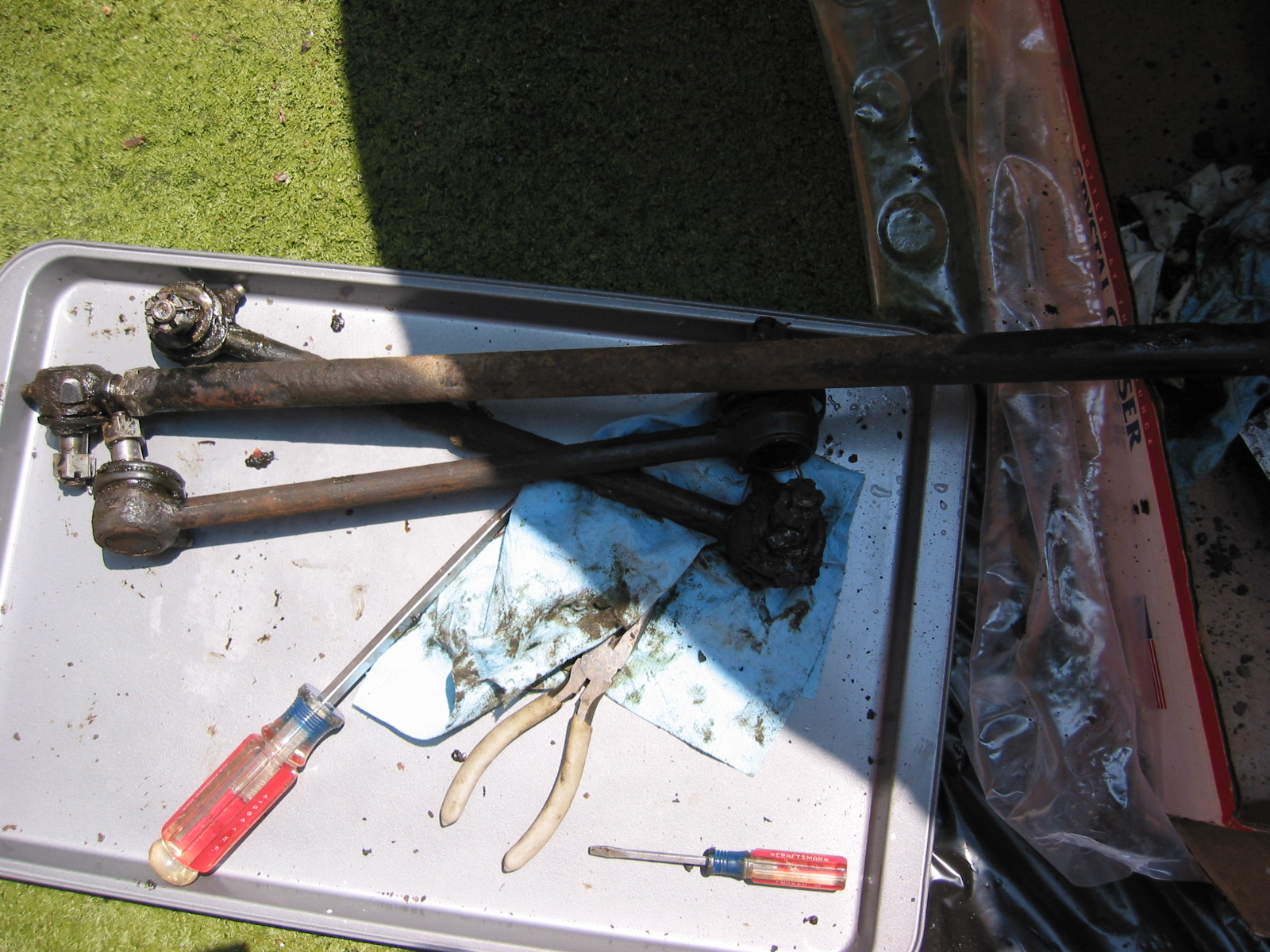
1:00 – The proper tie rods

1:45 – Draining and removal of radiator

4:00 – shock absorber removal

4:40 – Brake caliper removal and stowage

5:45 – Grease cap, split pin, castle nut, tab washer and brake rotor/hub removal

6:40 – Dust shield removal

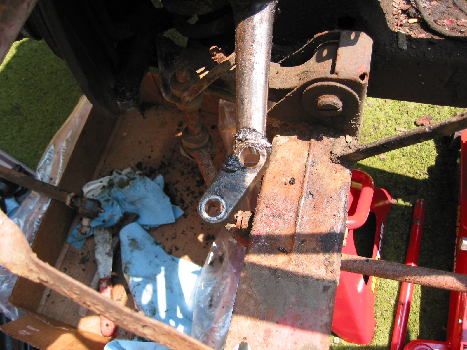
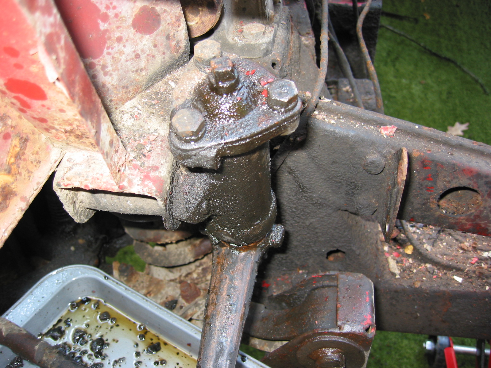
7:20 – Upper Trunnion/bolt

8:00 – Coil spring, spring perch, and lower shock mounting plate removal, tie rod end separation

11:20 – Fulcrum bolts, washers and bushings

11:20 – Cotter pin, fulcrum pin and king pin removal from the “A” arm assembly

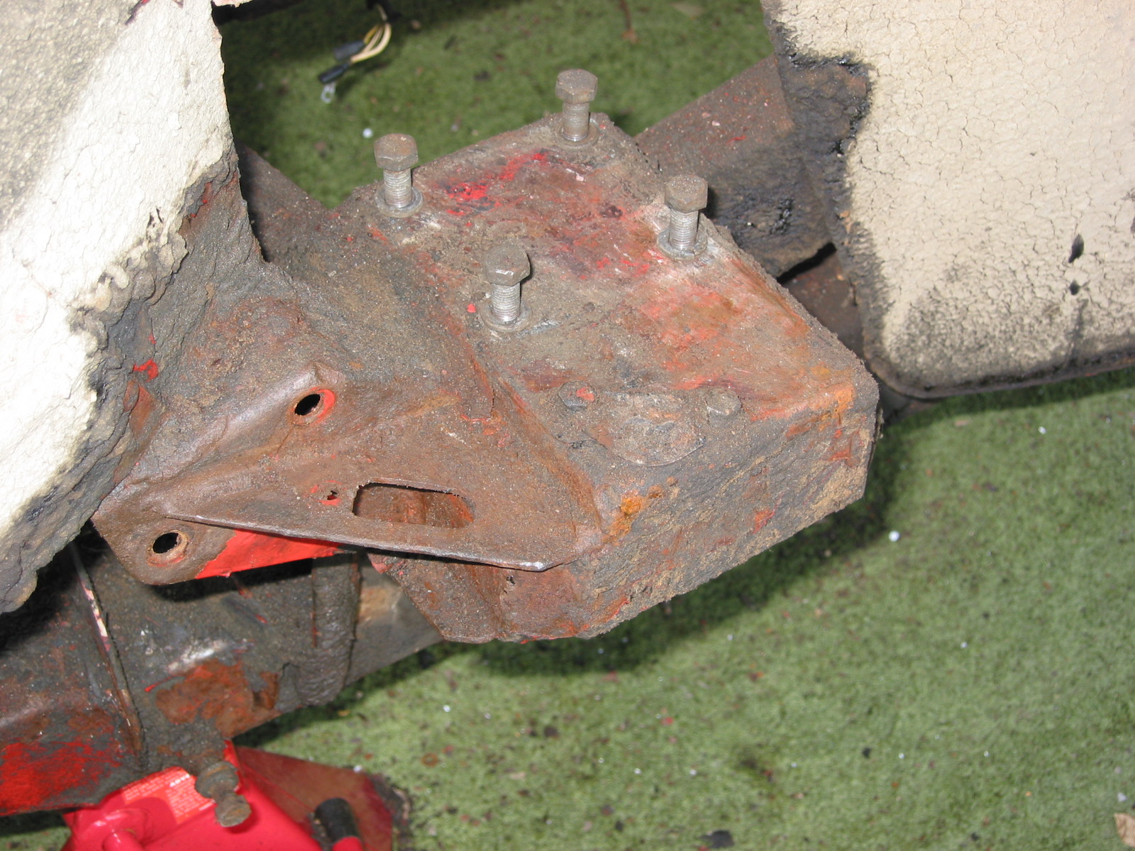
Now it is time to order some parts and clean and paint some of the components we will be reusing.

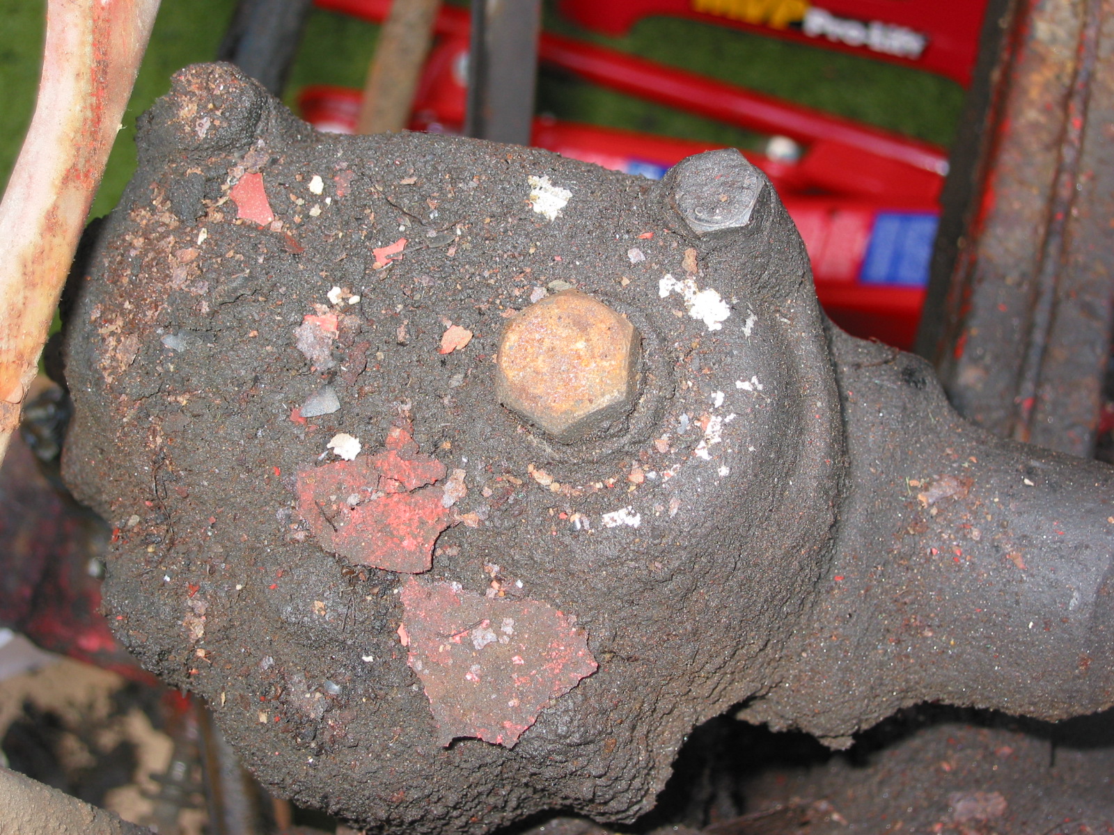
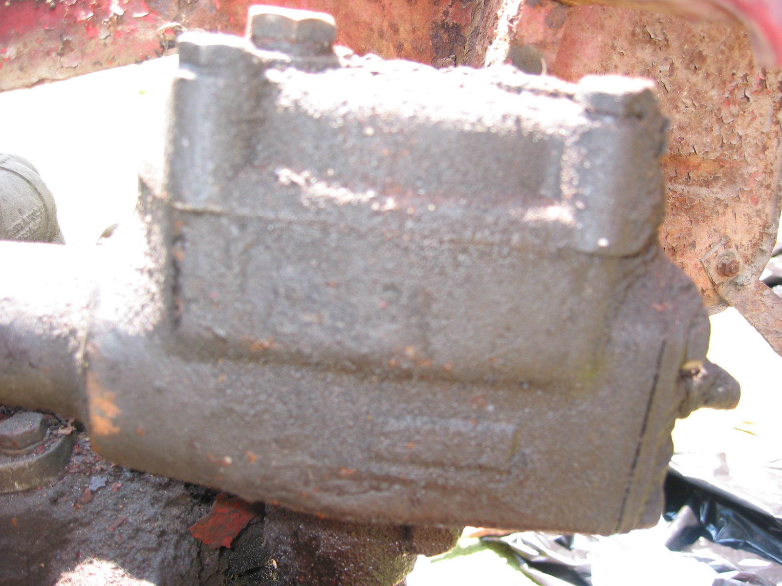
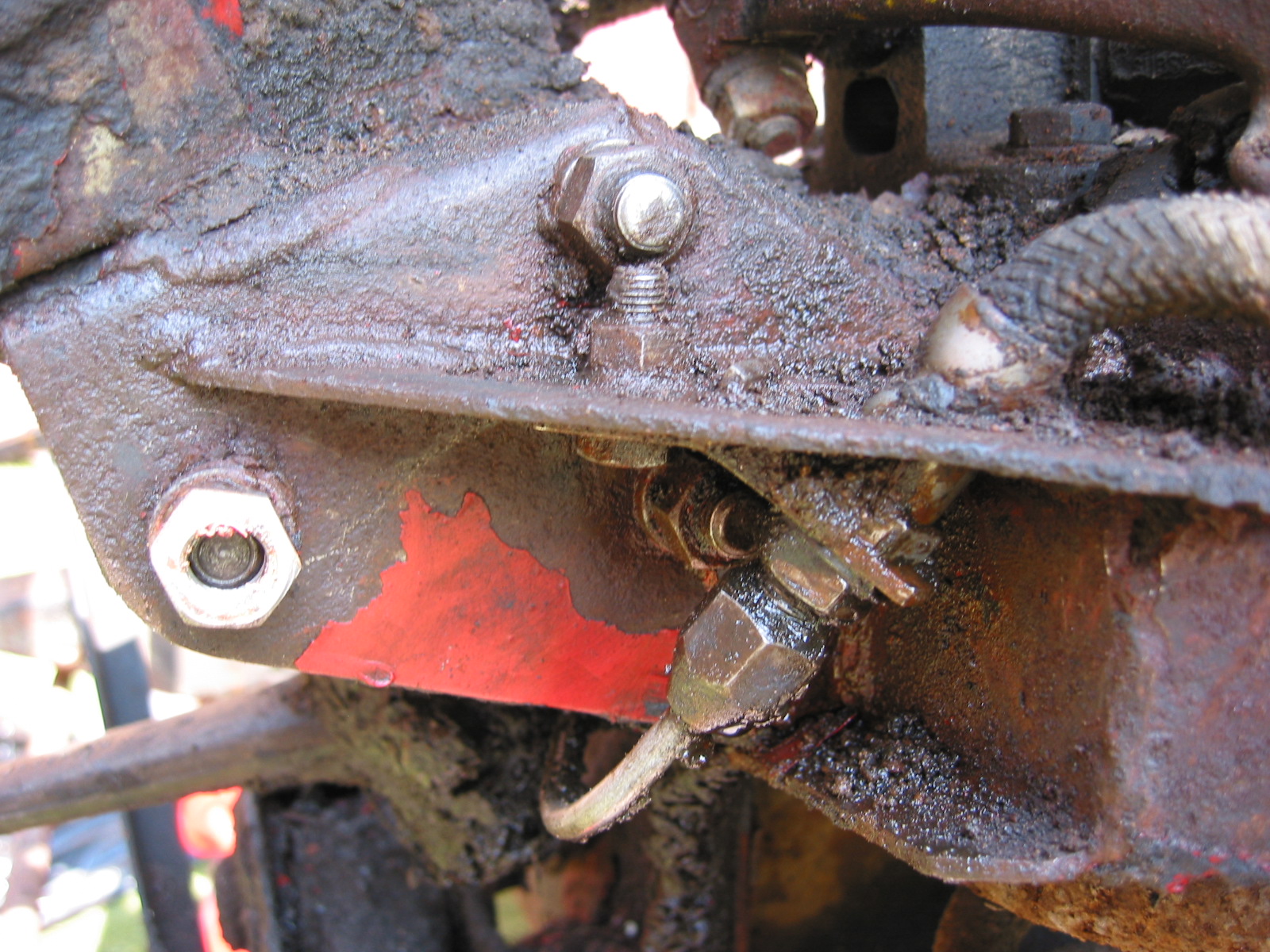
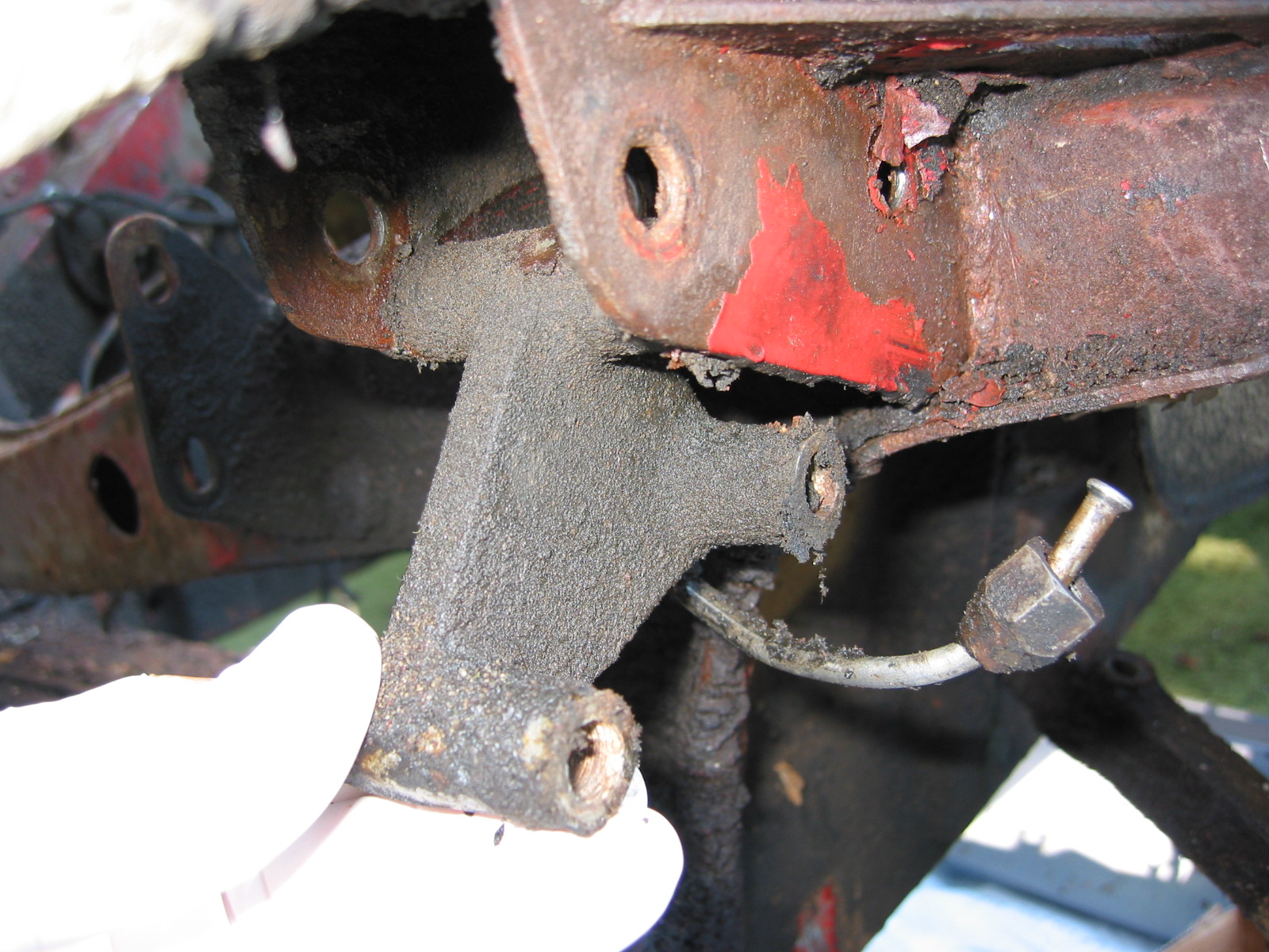
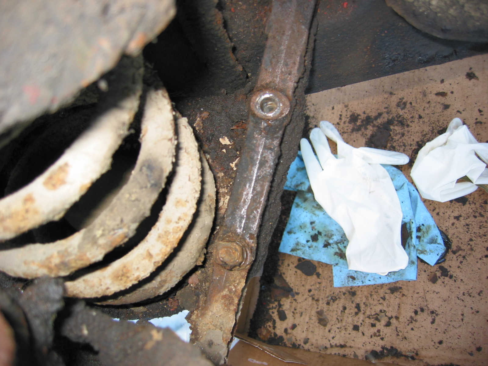
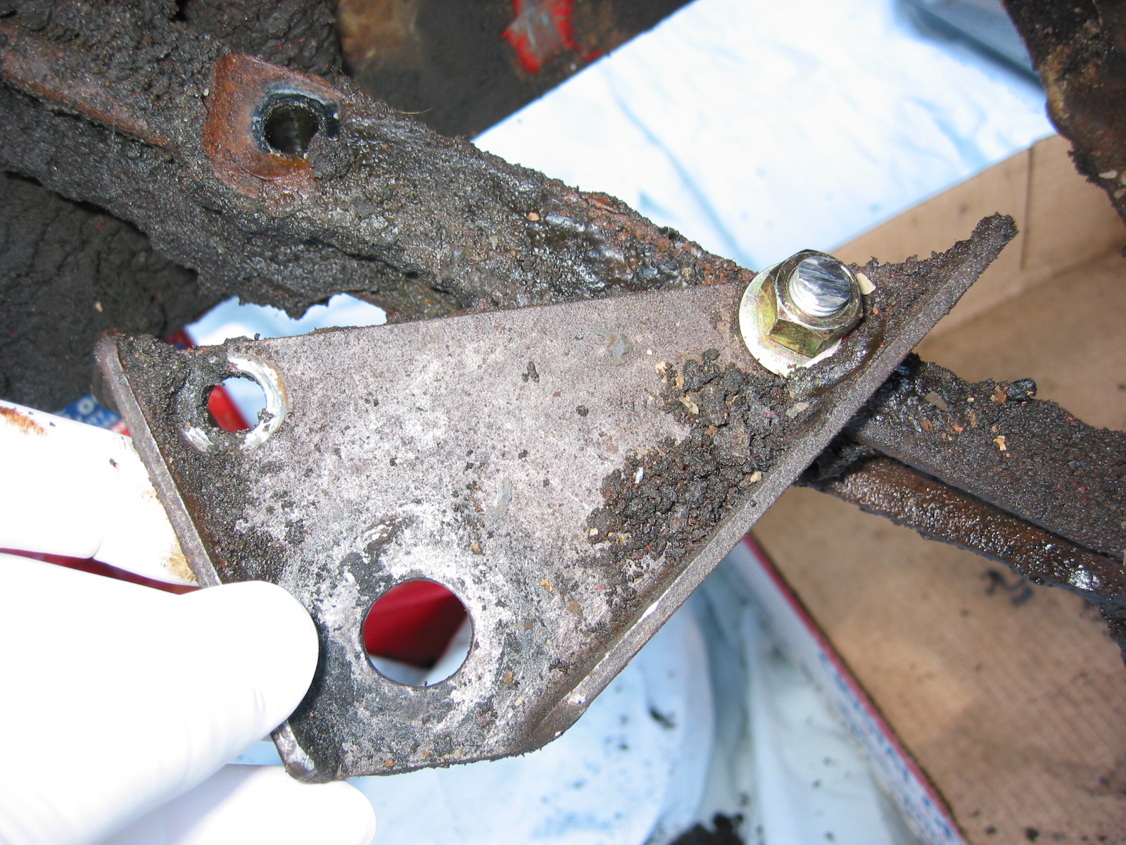
The RH suspension components that were not completely disassembled as they were removed from the car were dismantled on the work bench. All parts were cleaned and painted with POR 15. A hub puller was purchased and used to separate the brake rotor and hub.

Hub Puller

After the hub was separated from the brake rotor, the oil seal and bearings could be removed from the hub. New bearings and seals will be installed in the rebuild.

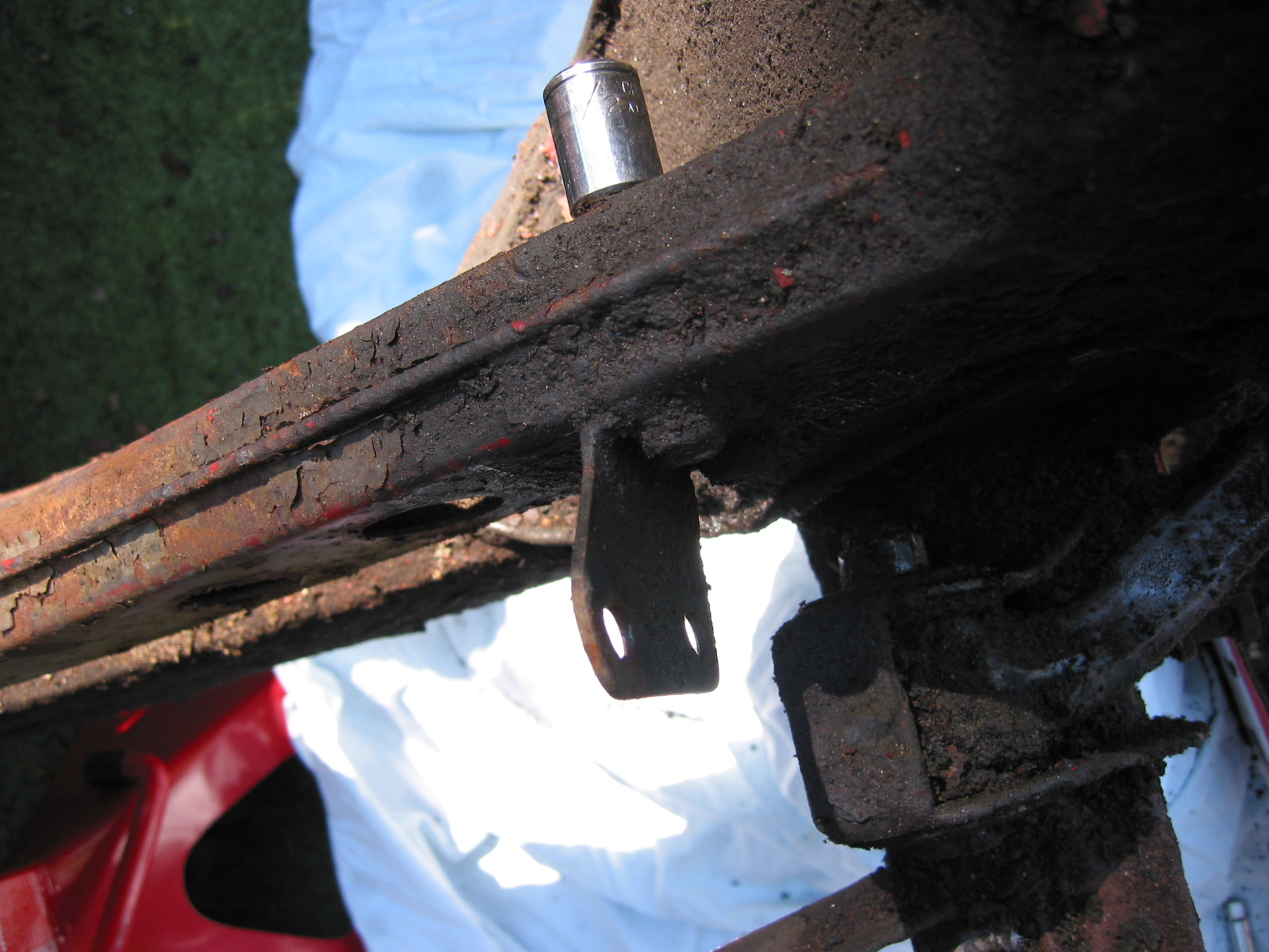
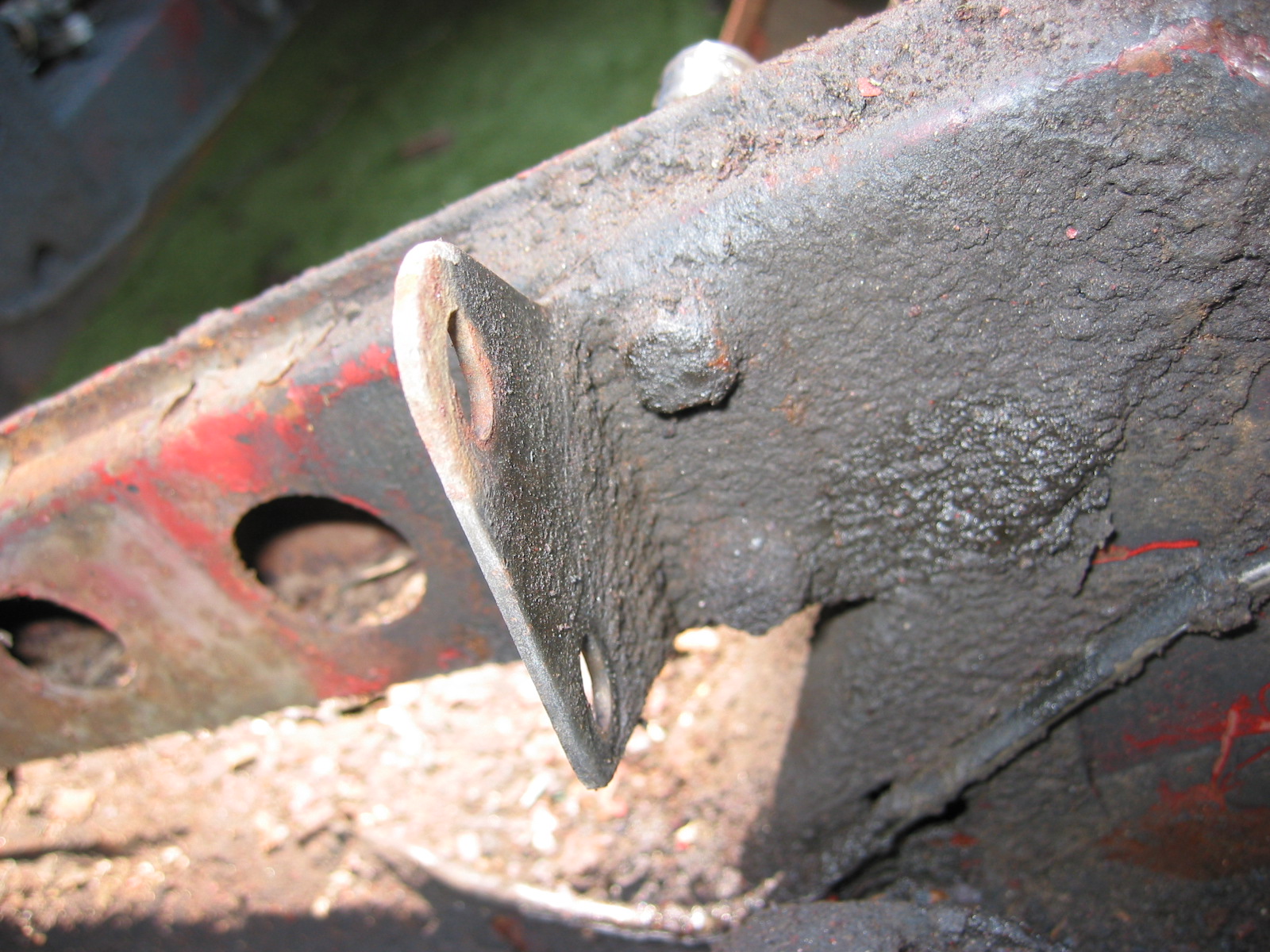
Video Episode Twenty-eight shows the completion of the dismantling process for the RH front suspension and the removal of the LH front suspension is begun.

https://vimeo.com/780172337/d31b642b97

The following steps are addressed in the video:

0:00 – Steering arm removal from the stub axle

1:05 – Spring dust tube

1:25 – Spring pan and bolts

1:45 – Upper Trunnion

2:00 – Hub separation from rotor

3:00 – Oil seal and bearing removal

3:38 – Bushing removal from the “A” arm

4:05 – Hub puller is used to separate hub and rotor

4:28 – Begin RH side front suspension removal


Chapter 9 – Disassembly

Steering Column Sealing Plate – Removed four sheet metal screws securing each of two sealing plates through which the steering column passes. Note the felt “gaskets” on the inside face of the plates.

Front Suspension and Steering  

The disassembly of the front suspension and steering assembly was a messy job. Lots of grease and grime built up over the years. I first jacked up the car. Disconnected the cross tube and side rods from the steering levers. The cross tube was 5/16” from the side to the nuts. Released cotter pins and took lever arms off. Used a fork and hammer to free the ball joints from the side rods at the inner and outer connections. Pulled the rods off.

Stub Axle Carrier, King Pin, Caliper, Dust Shield

Cross Tube, Ball Joint, Steering lever and Side Rod

RH Steering Lever

Stub Axle Carrier, King pin, Dust Shield

Cross Tube and Side rods

LH Steering Lever

Cross Tube Ball Joints –  were removed by repeating the same action as above. Unscrewed the mounting bolts from the steering box. This requires removing the 7/16” bolt that secures the left brake flexible fluid hose. 

Steering box – After removing the mounting bolts, the box and rod can be pulled out through the front of the car.

Steering Box in Place

Steering Box Oil Filler Cap

Steering Box Side View

Steering Box Mounting Position

Steering Idler –  Unscrewed three bolts to the mounting bracket and lifted the idler away.

Steering Idler

Steering Idler 2

Aluminum Spacer Block Mount

Aluminum Bracket Spacers – for steering box and steering idler were removed. They appeared to be interchangeable.

Removing Aluminum Spacer Block

Aluminum Spacer Block

Front Suspension Coil Springs – Removed two bolts and nuts at a diagonal. Nuts on top and bolt heads under bottom spring bracket plate. (this is opposite the picture in the manual so we need to check other cars before reinstalling) Inserted two threaded rods with nuts into those holes. Then removed the other two mounting bolts and nuts. Finally, gradually relieved pressure on the threaded rods until spring tension was removed. The left spring was broken on the bottom coil.

Coil Spring and “A” Arm with spring pan removed

Spring Pan

Anti-Sway Bar Bracket

Tub on Stands

Front Suspension Arms, Brake Rotors and etc.  It was difficult to remove the arm bushings. They required extensive “torching” for heat and hammering, but all eventually released. Then removed the fulcrum pin securing the shock absorber arms and the four bolts to the shock towers on the frame. One hole on the right tower had been stripped and broken. Each shock had the remains of rubber rebound buffers on the towers. Once the shock was removed this permitted the removal of the left and right king pins and assembled units.

Front Shock Perch

Bent “A” Arm Bracket

Radiator 

Radiator Brackets were removed from the frame. Two 1/2” bolts for each bracket. We will be replacing the original radiator with an aluminum unit from Cape International.

Radiator Lower Mount

Radiator Mount Bracket

Radiator Brackets Removed