Other than installing the finished motor and the body components I am now down to just a few bits here and there. I am starting to get excited about the finished product after so many months (years actually!) of hard work.
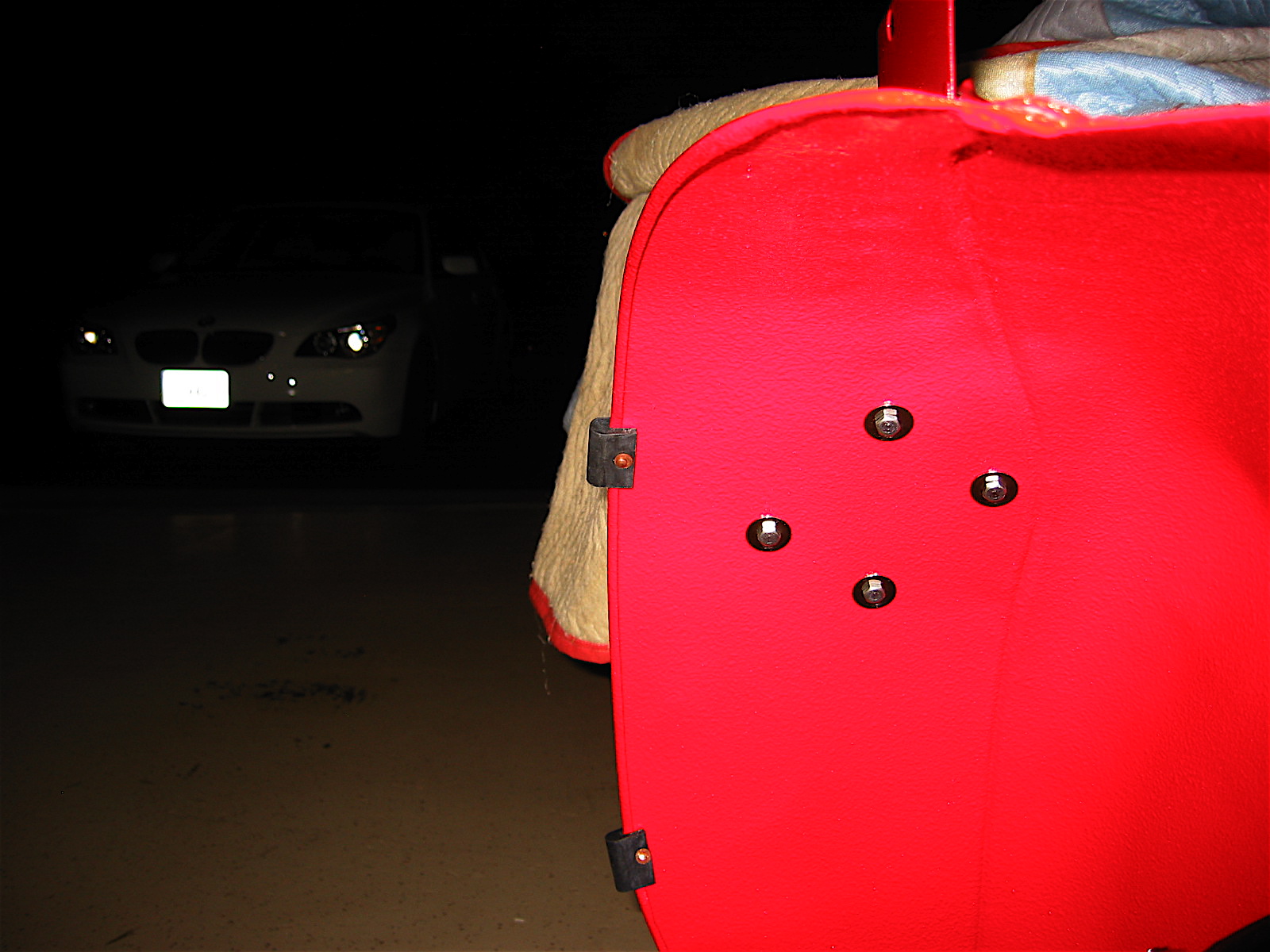
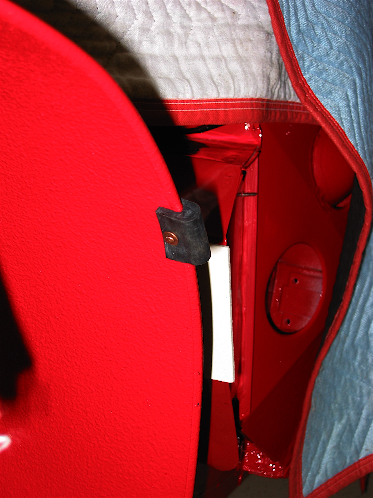
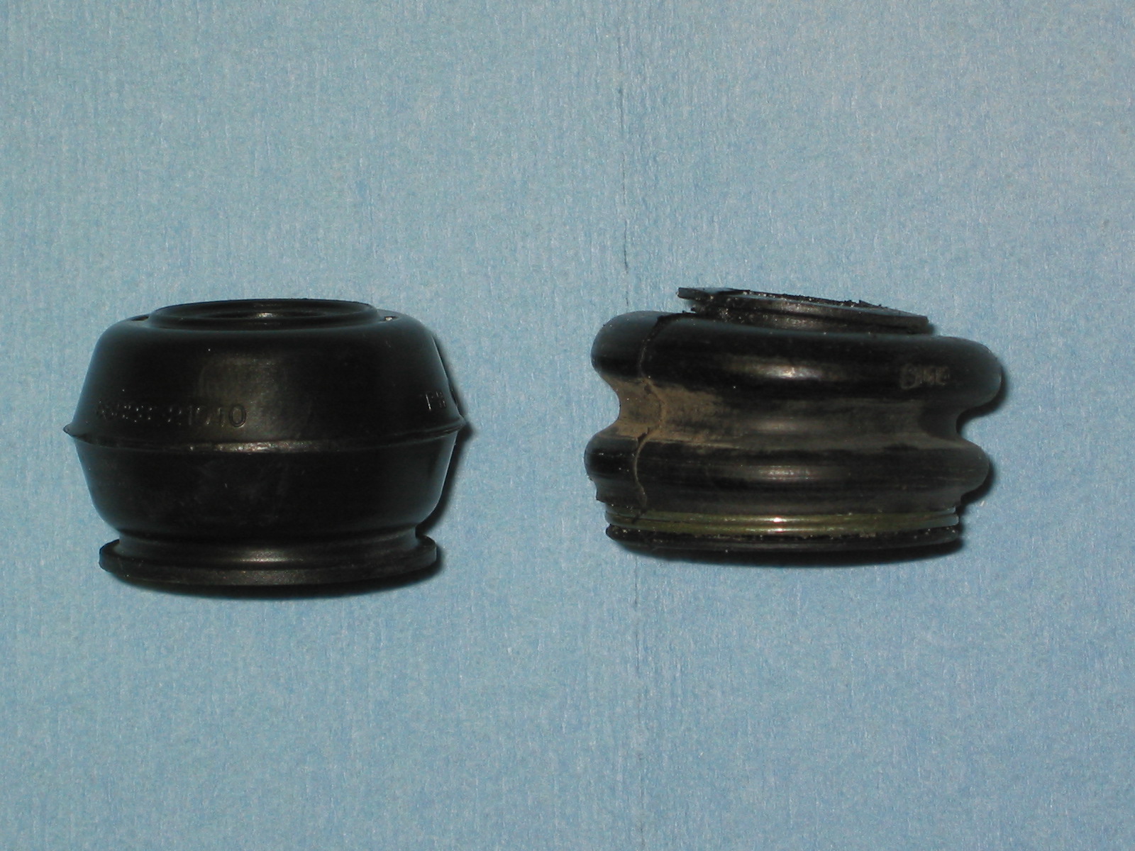
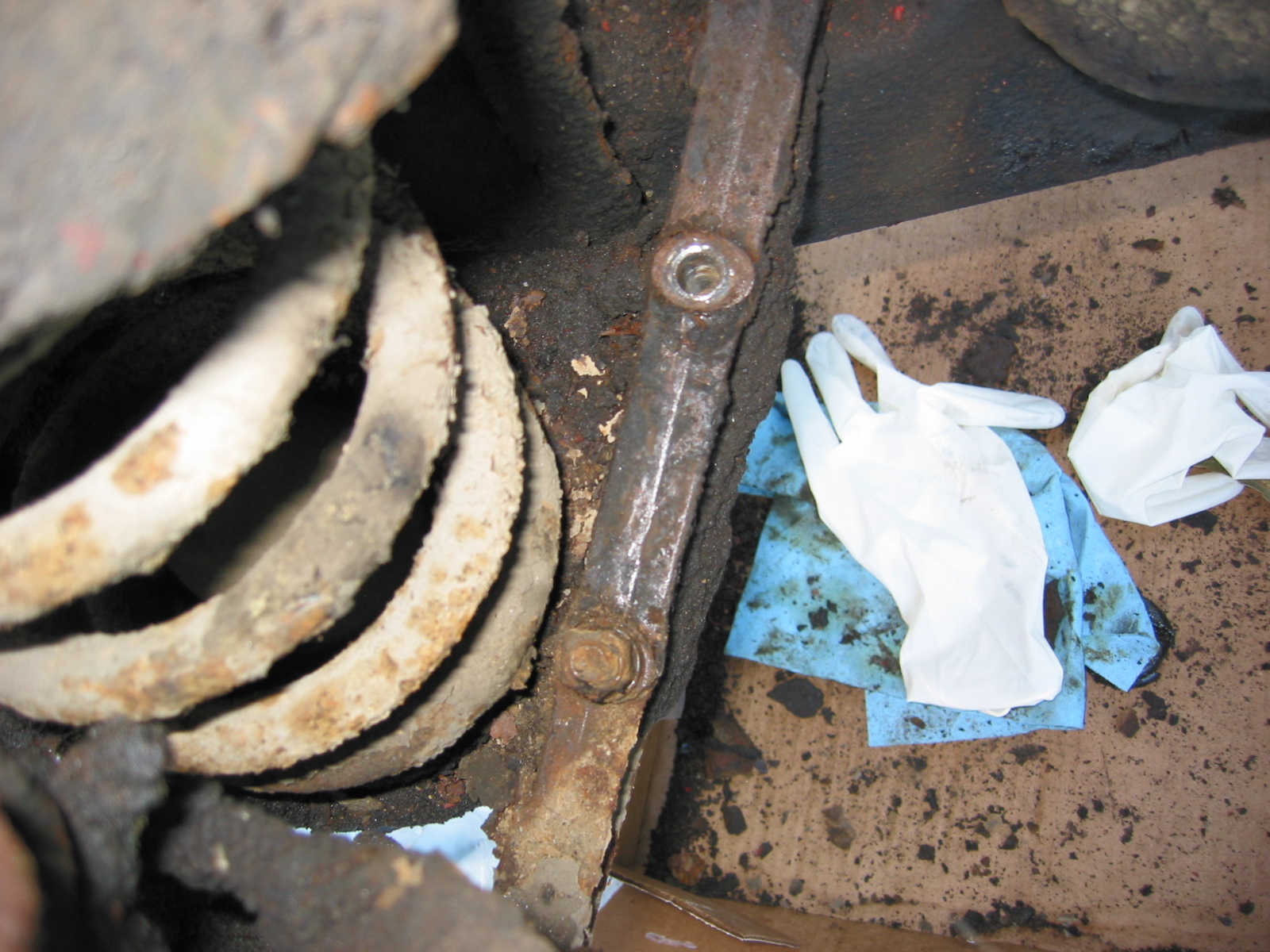
At the factory the two rubber buffers that mount to each of the wheel arch assemblies were fastened to the assembly before painting the tub, but I installed them after painting to make sure that all surface areas were covered well with paint. Copper split rivets and washers are used to fix each buffer to the wheel arch.

Rubber Buffers

Rubber Buffers 2
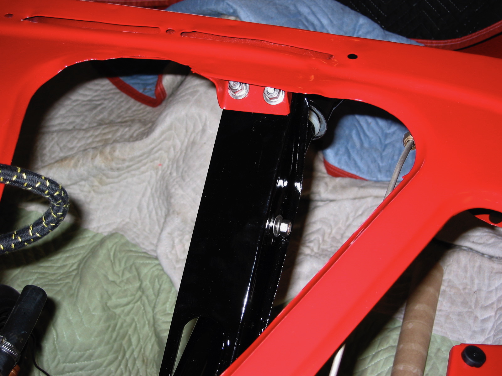
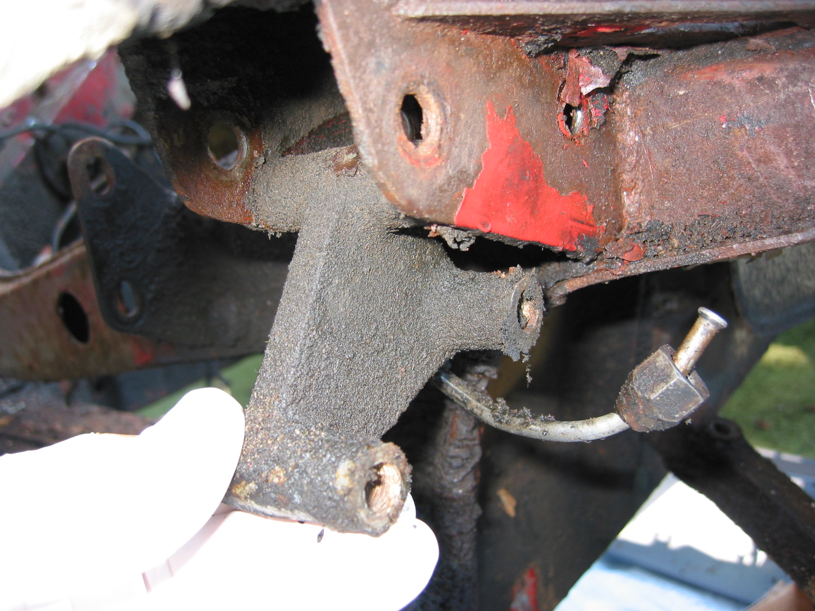
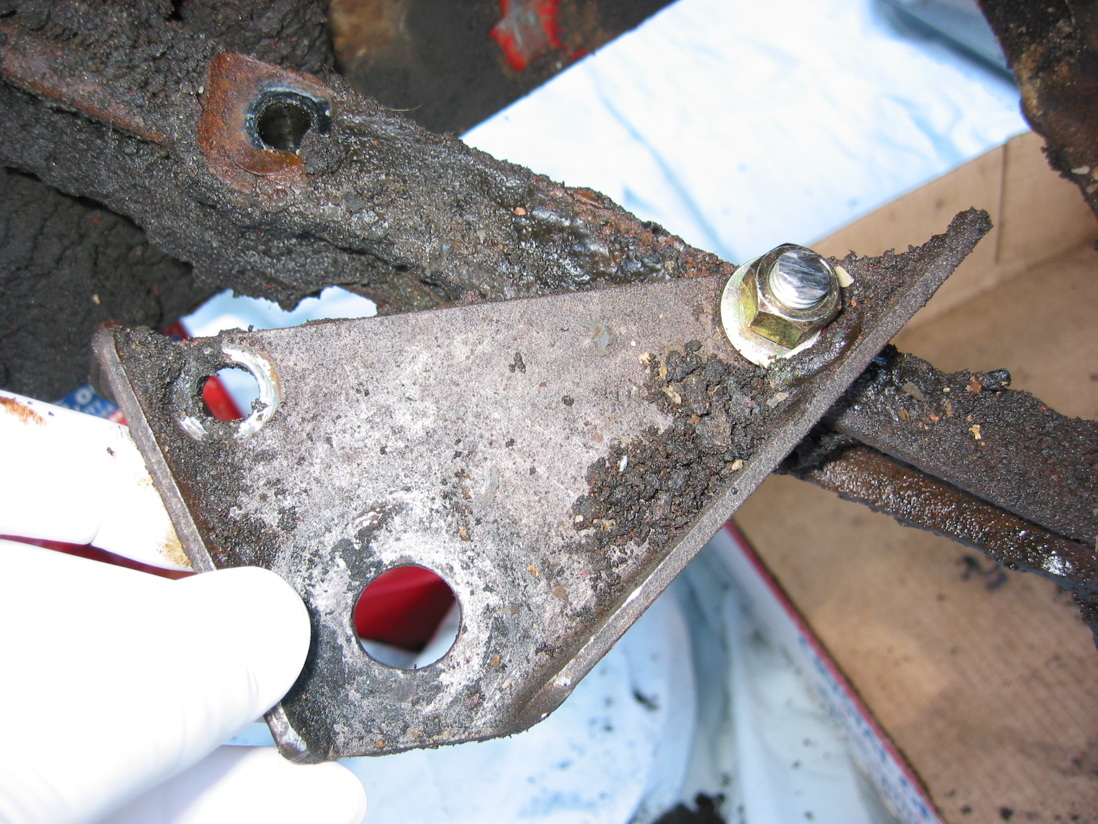
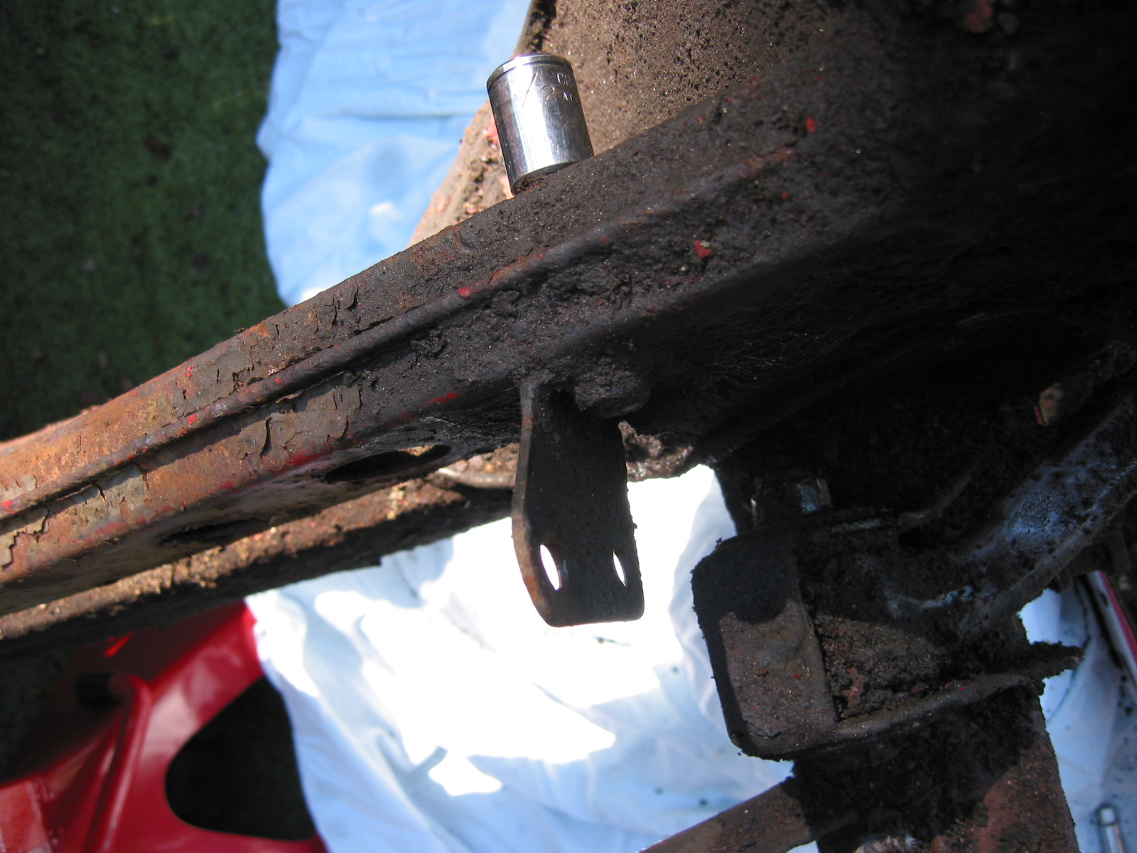
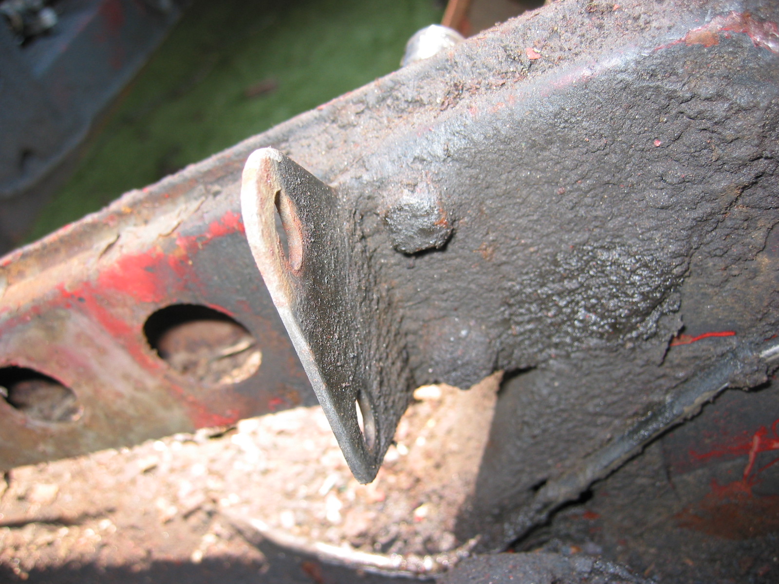
The front wing support brackets were added next. I carefully attached them in the same positions they were in for panel fitting.
Front Wing Support Bracket LH
Front Wing Support Bracket RH
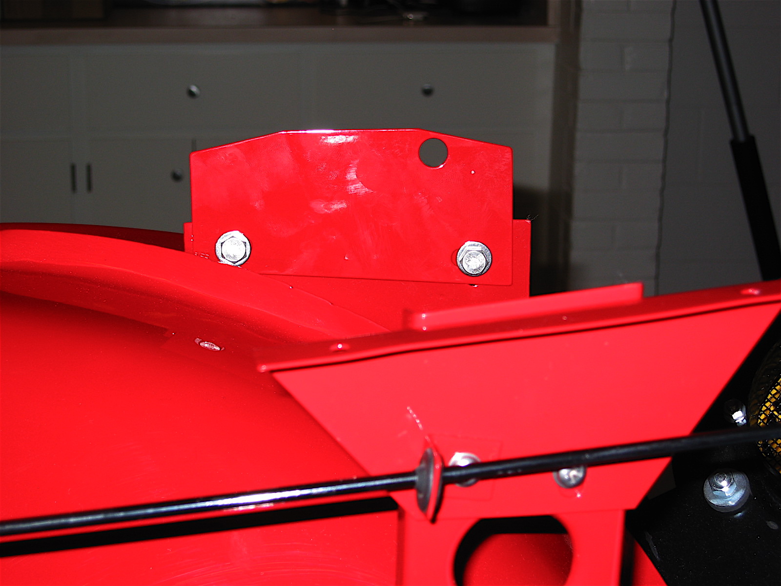
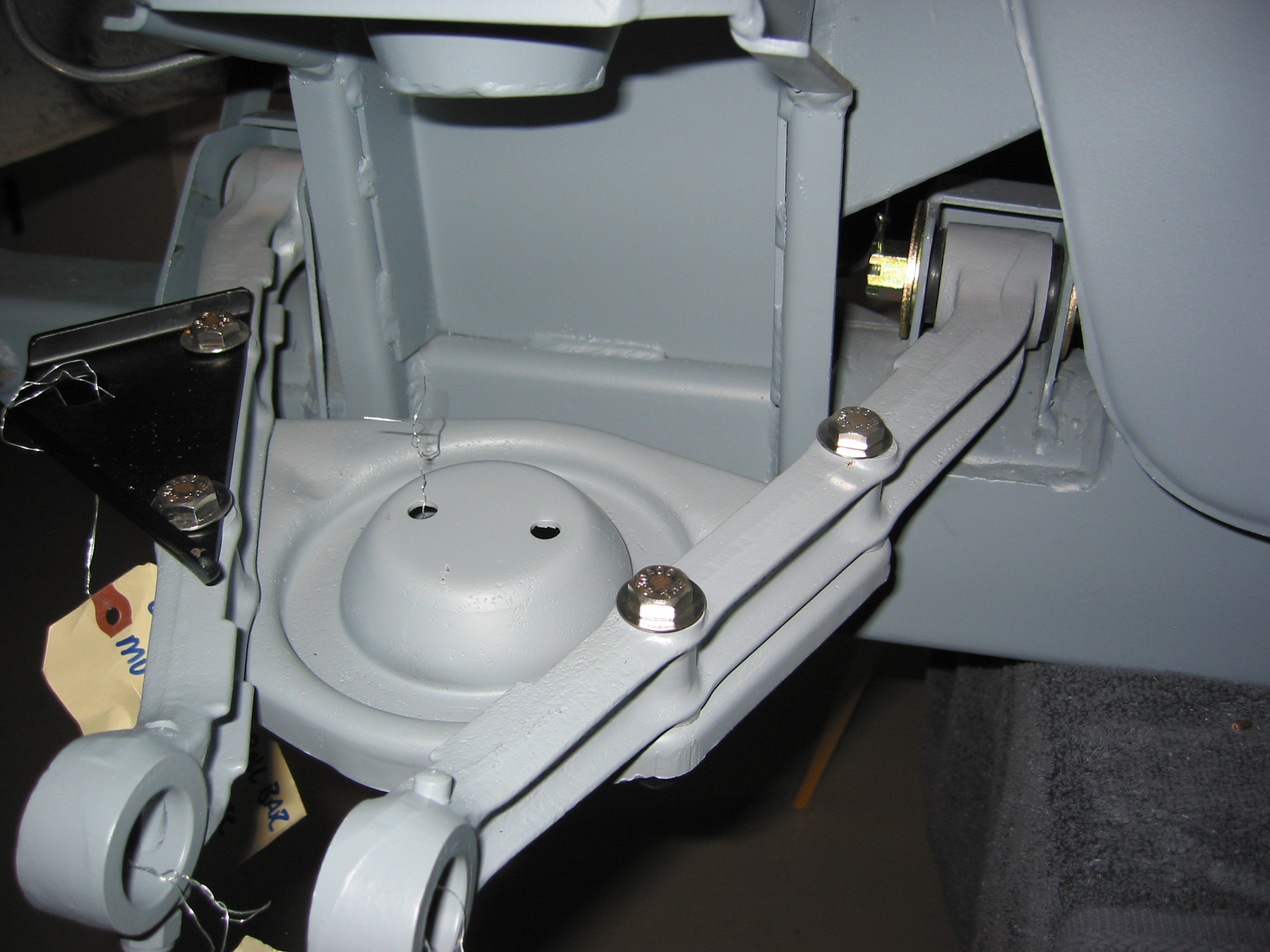
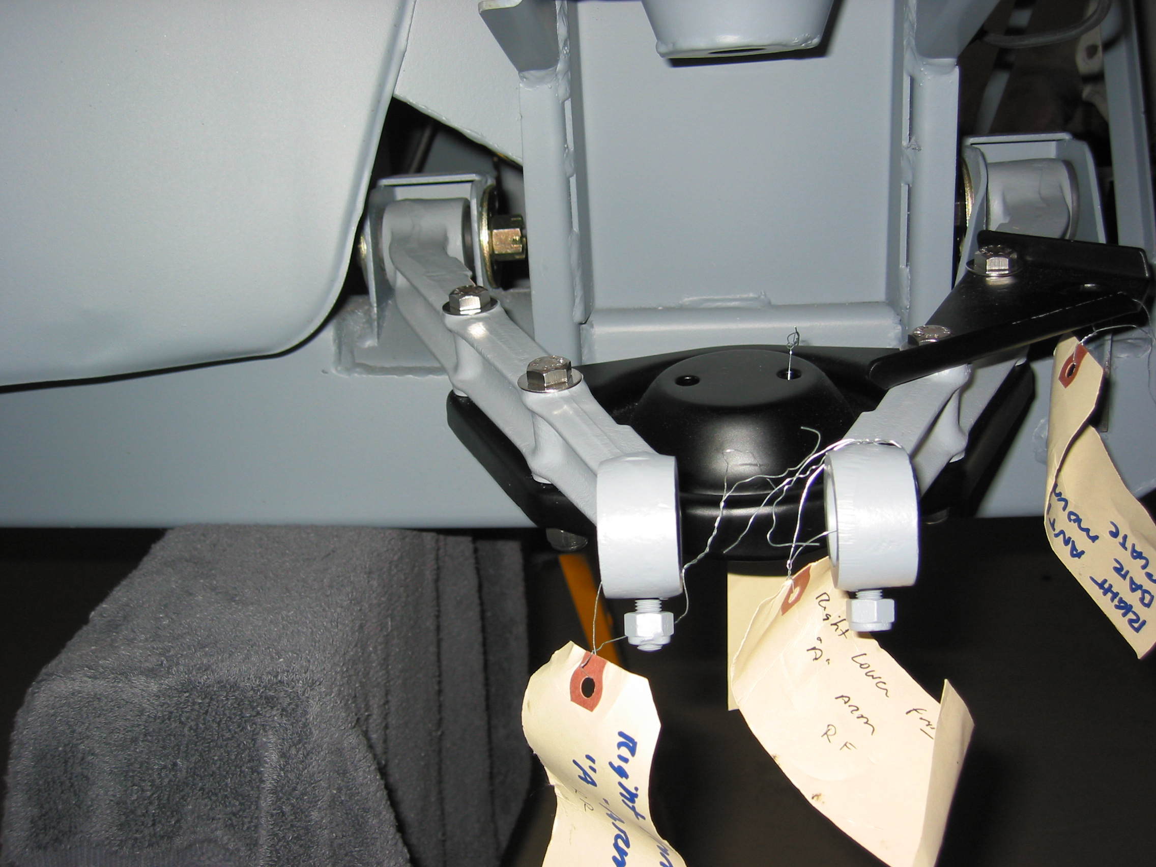
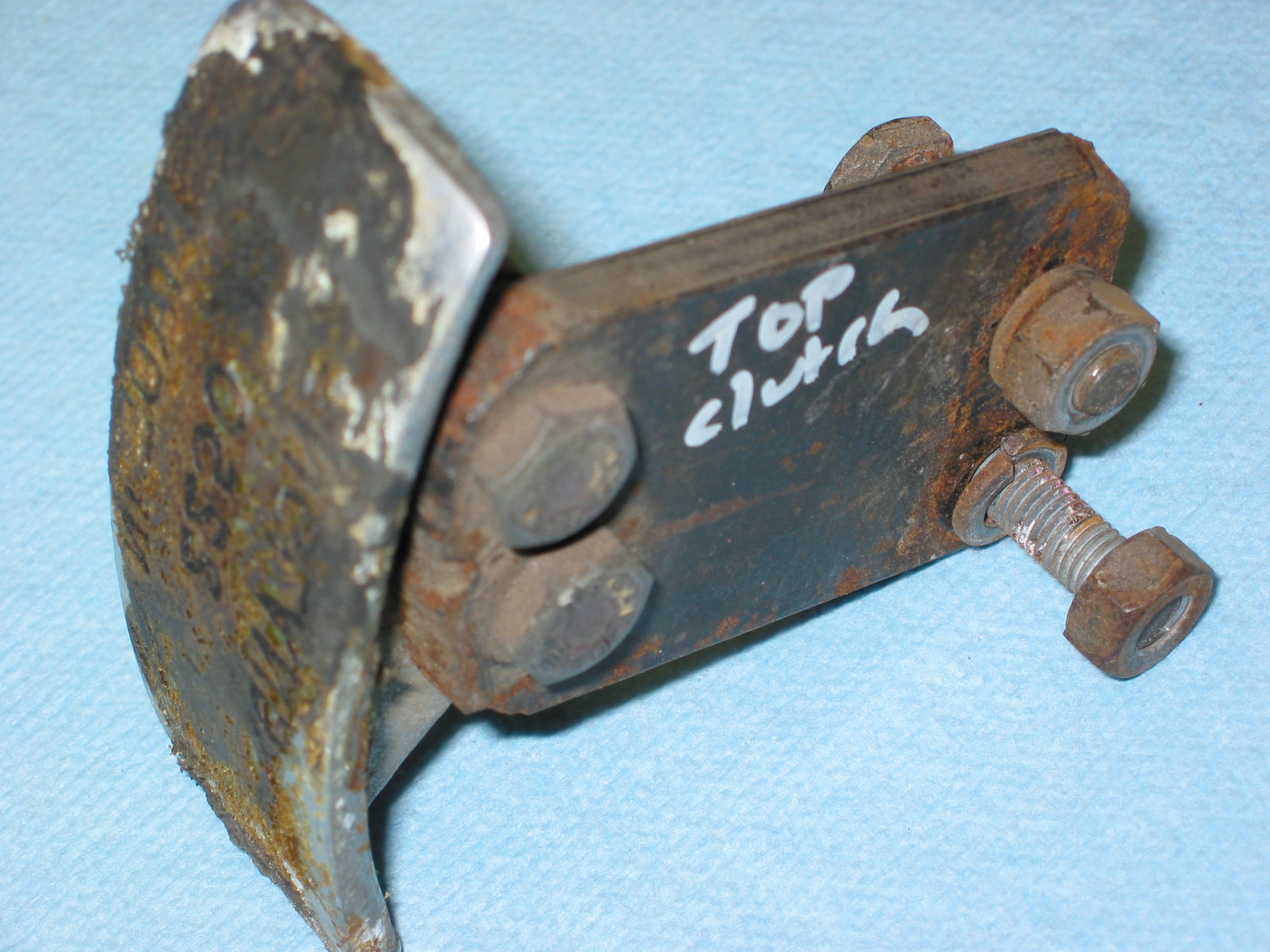
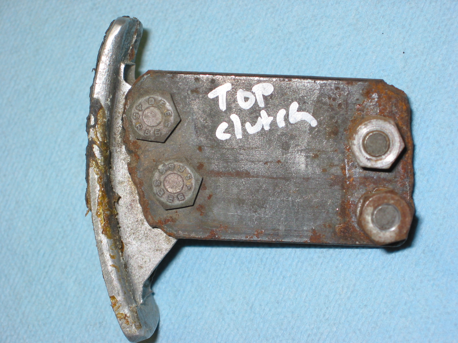
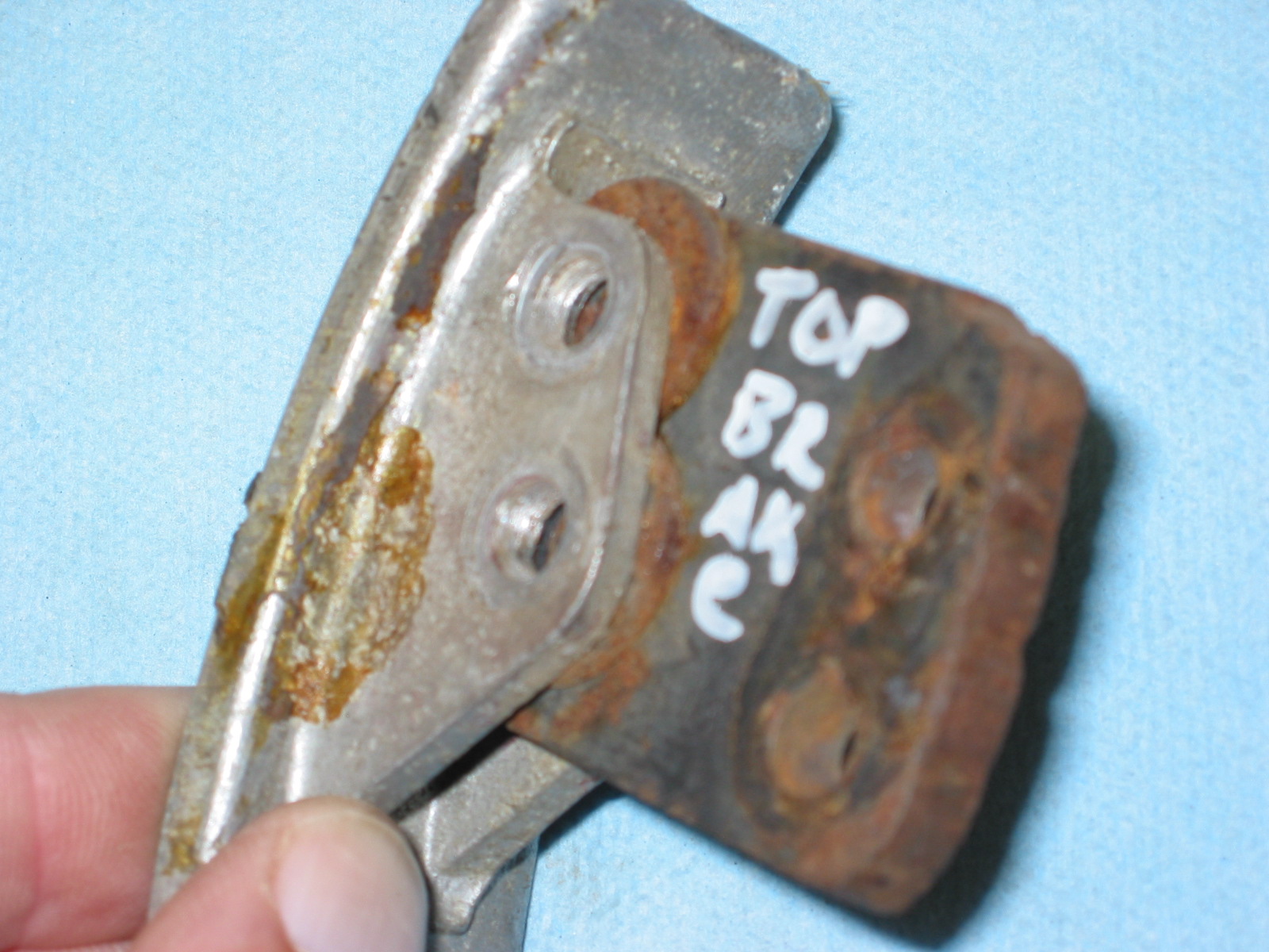
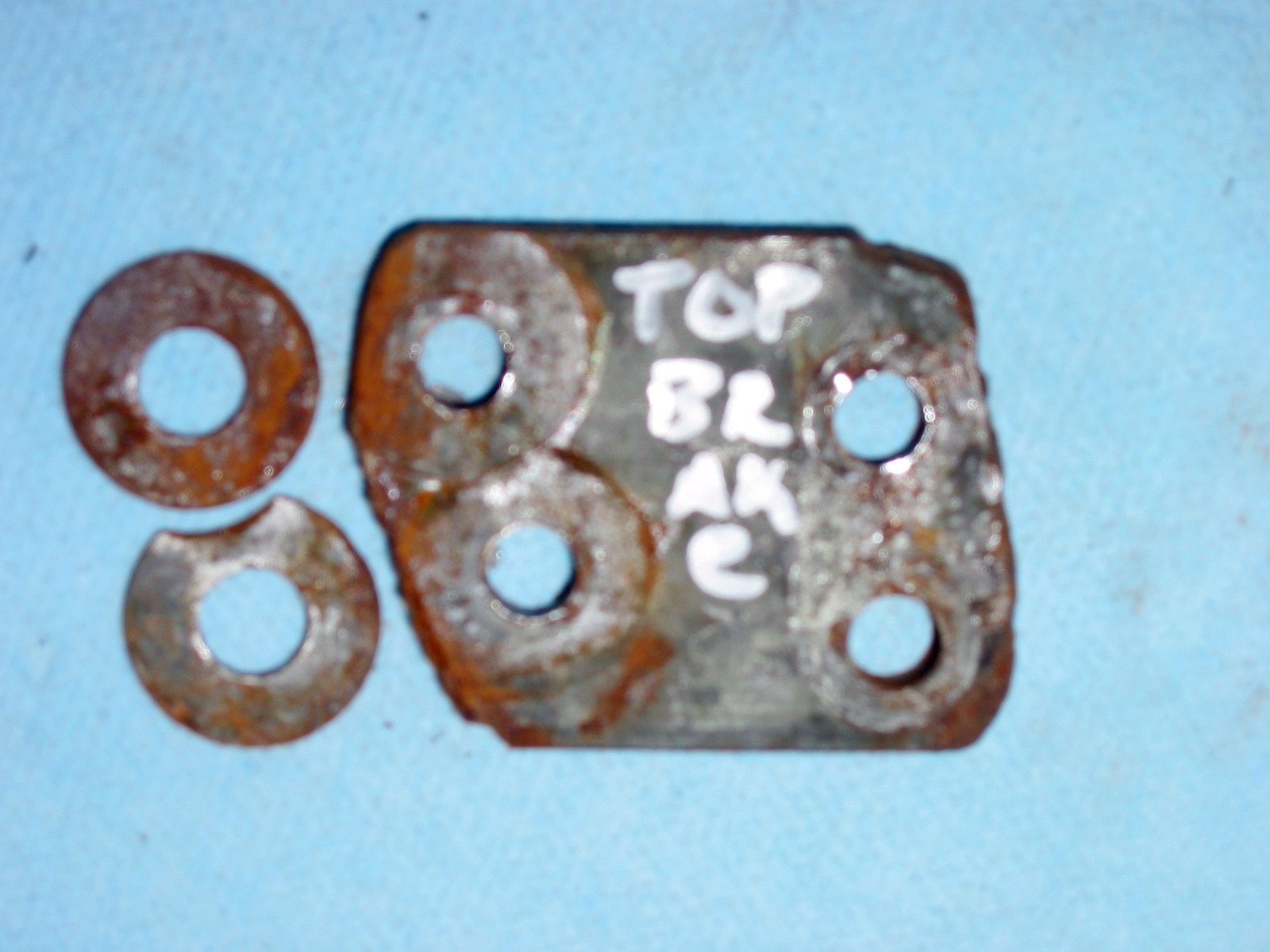
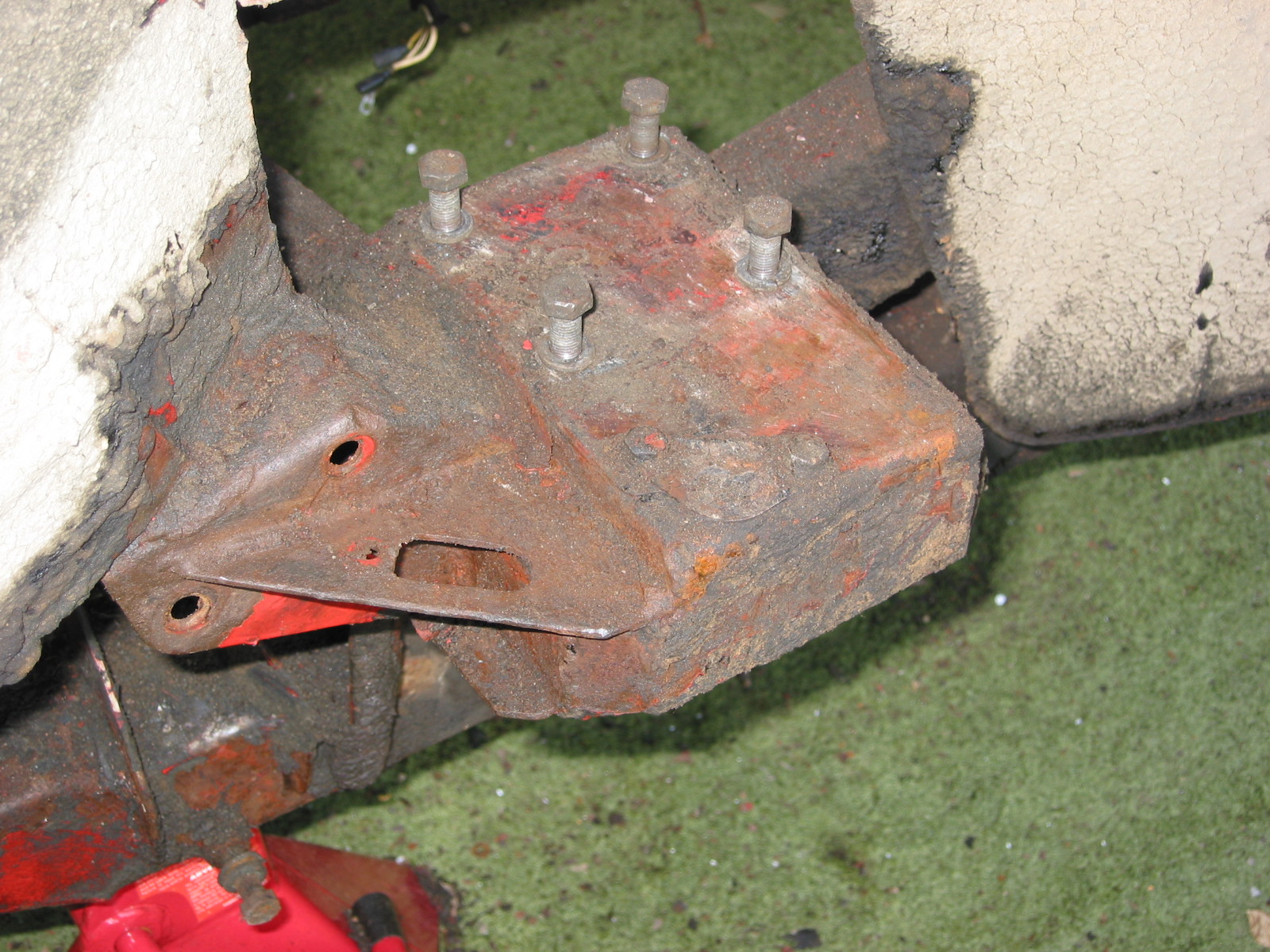
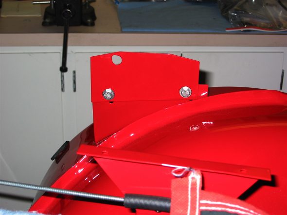
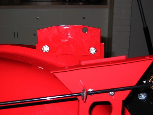
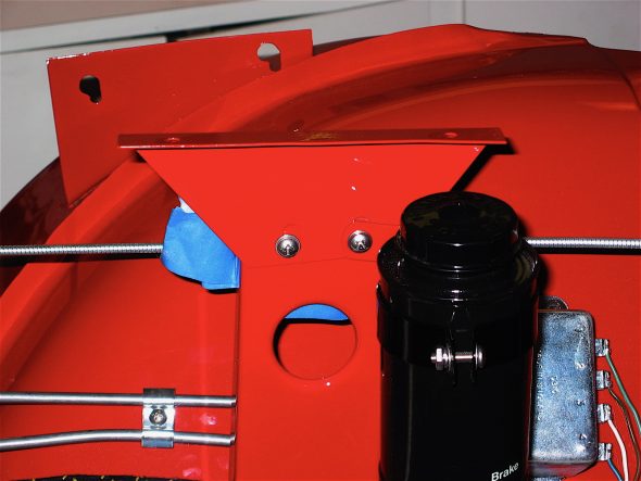
The bonnet support plates were added next. These were not fastened tightly so that they might be adjusted easily after the front shroud was installed
LH Bonnet Opening Support Plate
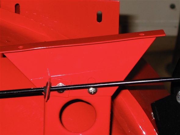
RH Bonnet Opening Support Plate
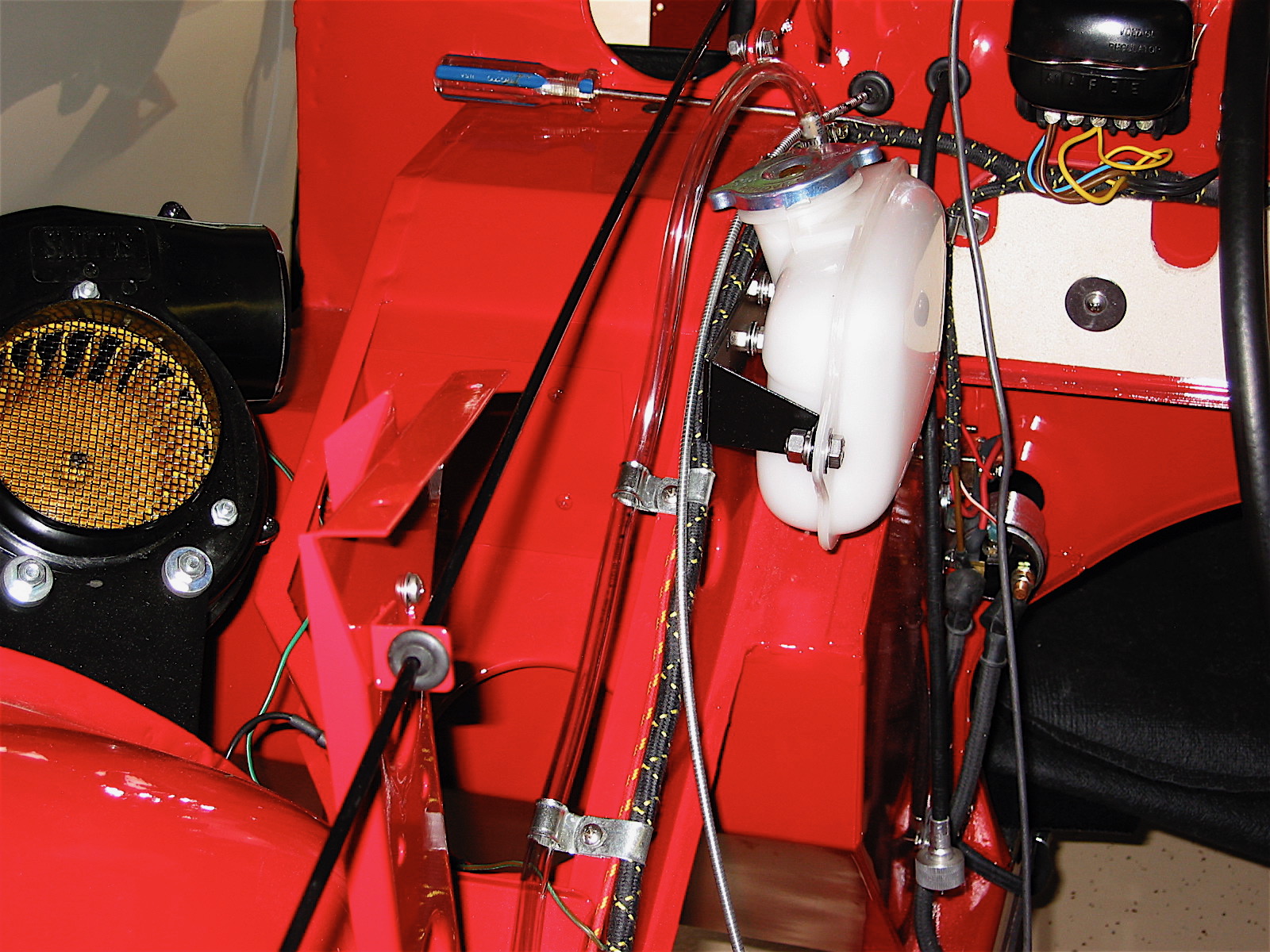
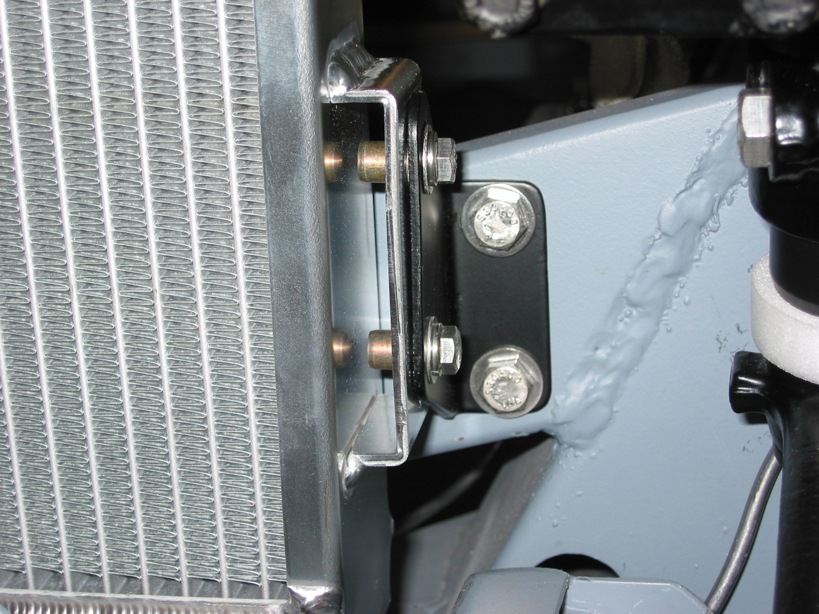
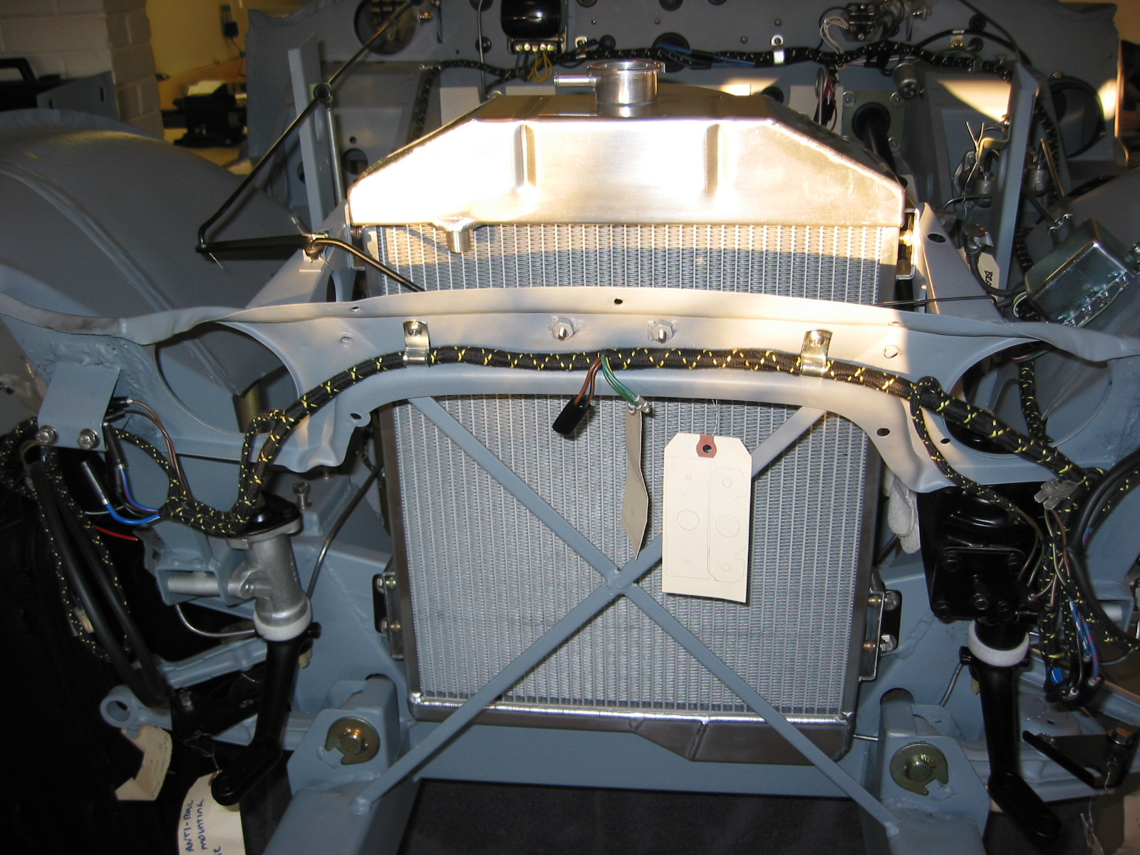
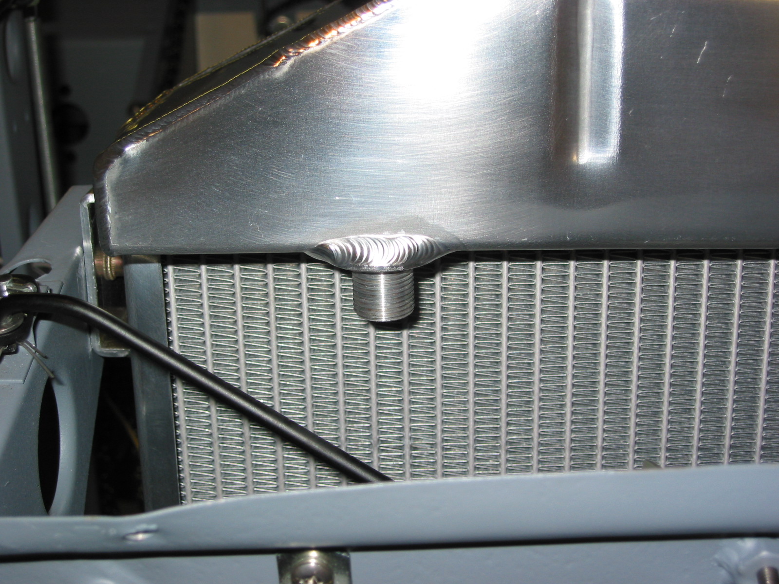
To avoid losing radiator coolant I decided to add a coolant overflow reservoir tank to the Bloody Beast. I fabricated a bracket to mount it to the superstructure and ran a clear hose parallel to the wiring harness that runs down the RH firewall brace.

Radiator overflow tank
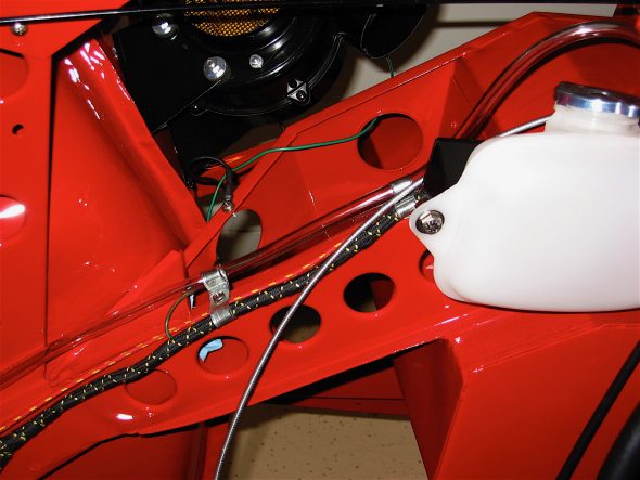
Radiator overflow hose routing
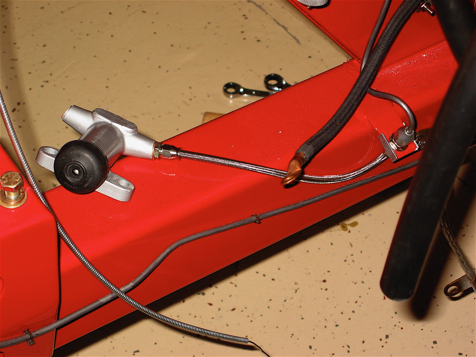
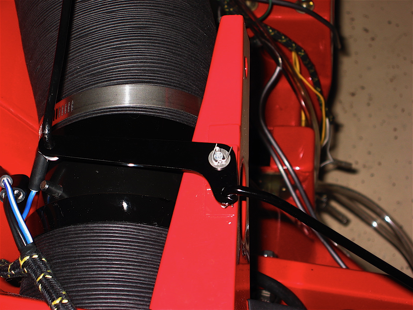
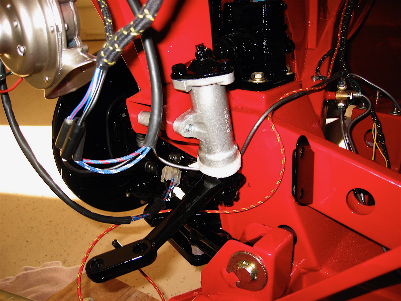
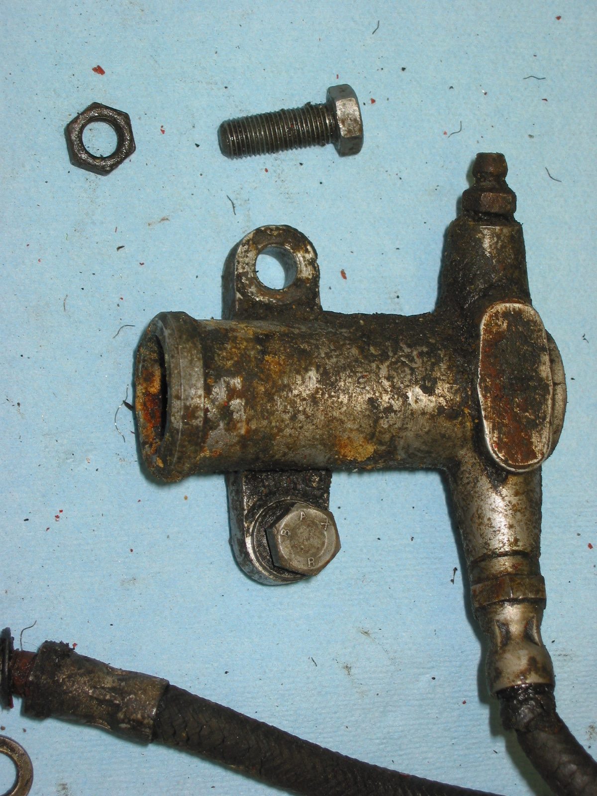
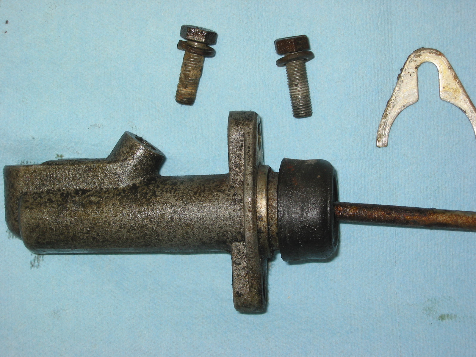
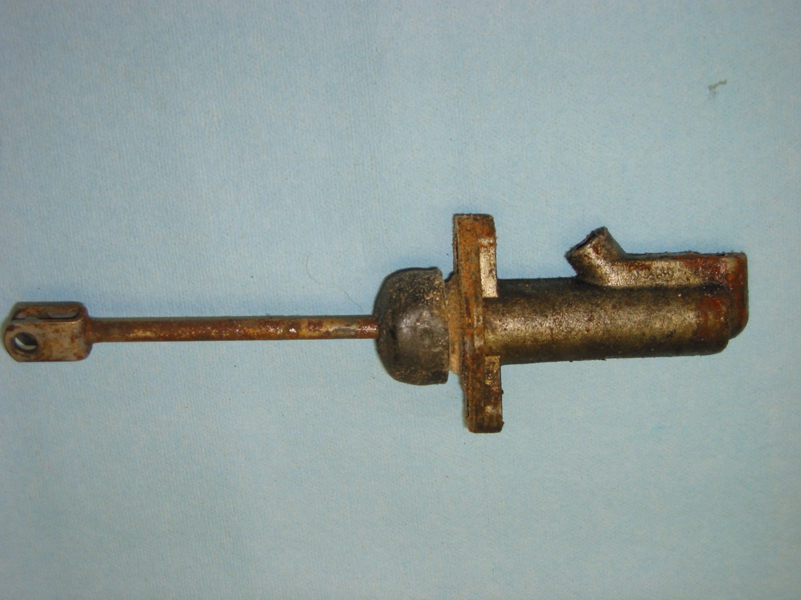
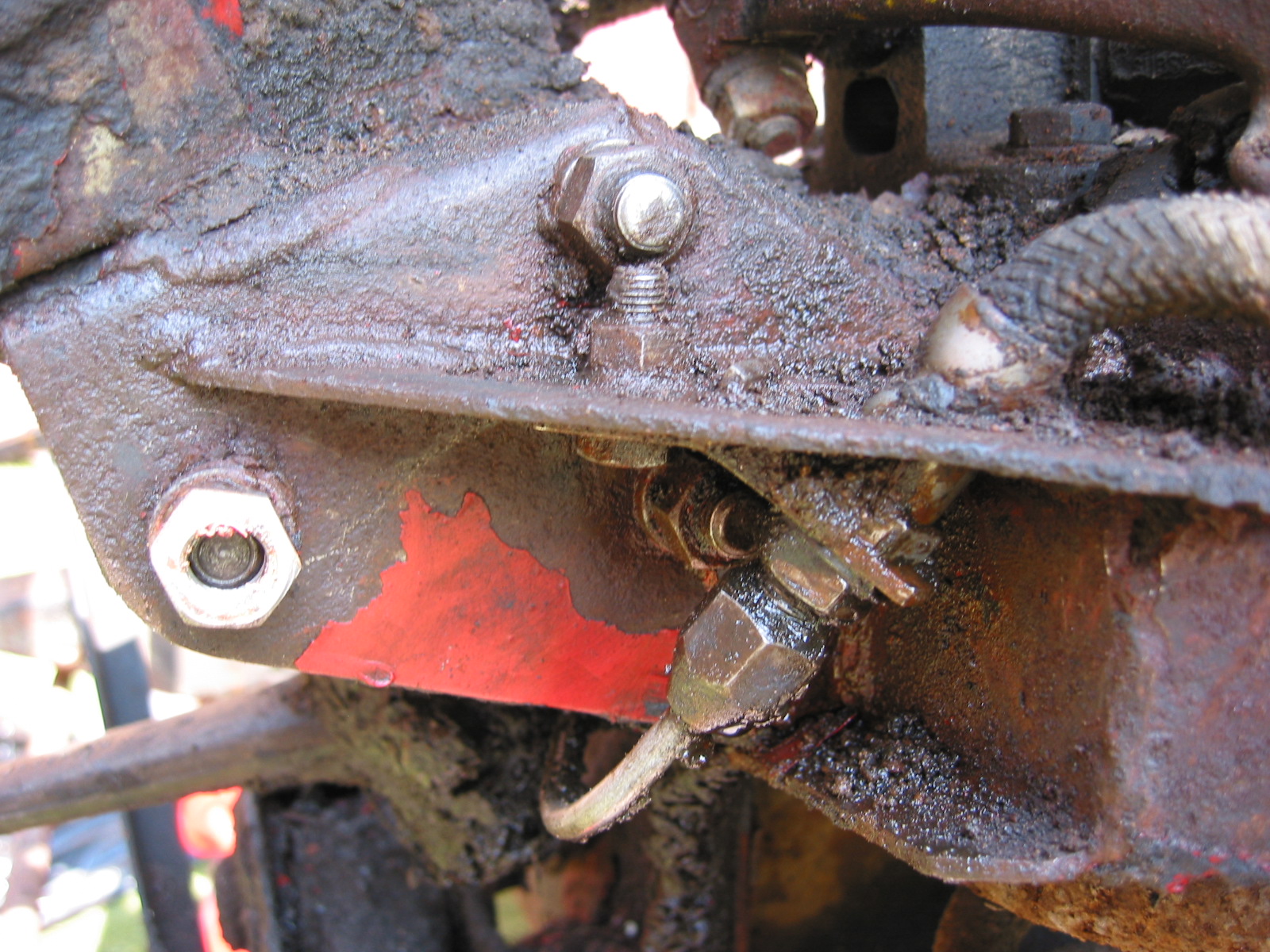
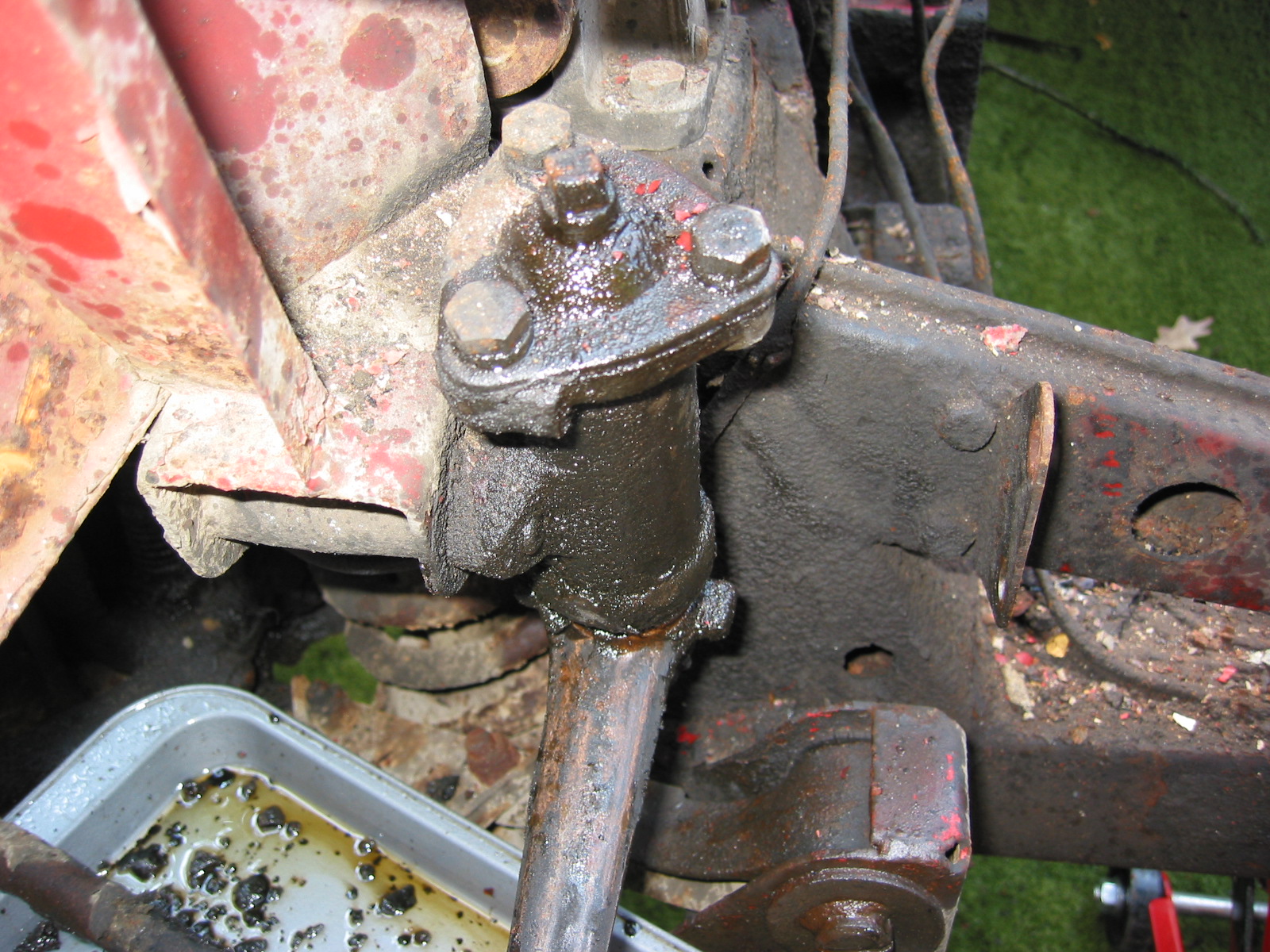
I purchased a stainless steel braided hose for the clutch slave cylinder from Moss Motors. I attached it to the new Lucas slave cylinder and then inserted it into the retainer clip on the frame to screw it into the clutch pipe running up the RH footbox. Doug Reid aka Mr. “Finespanner,” fabricated a short bleeder pipe for me that will mount on the bell housing making it much easier to bleed the clutch in the future.
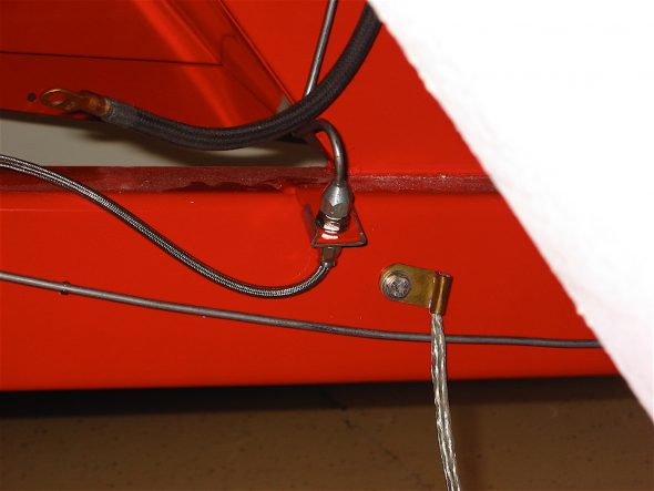
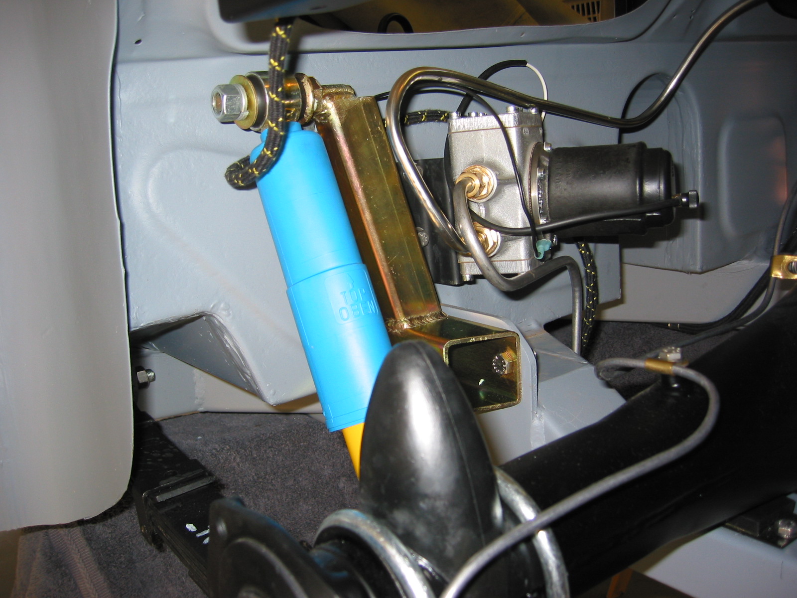
SS Slave cylinder hose

Slave cylinder
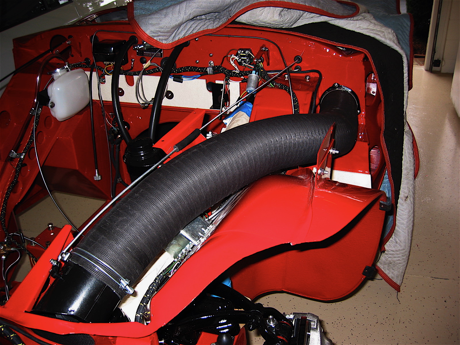
The fresh air hose installation was made easier because of the “pre-fitting” done prior to the tub being painted. The LH hose quickly went into place and the clamps and bracket for the control cable were all tightened.

LH fresh Air Hose
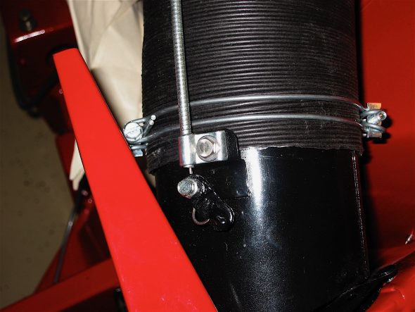
LH Fresh Air Hose
The modern heater (contrasted with the original Smith’s heater radiator box) that I am using from Cape International has it’s own blower fan, and therefore, the original heater blower can be used to circulate fresh air into the passenger side of the cabin. I installed an air intake assembly upside down and close to the front end of the LH hose so the the control cable from the cockpit heater panel could be used to open and close the air inlet valve assembly. It all works like a charm. Perhaps now my victims, I mean passengers, won’t roast while on long sojourns in the summer.

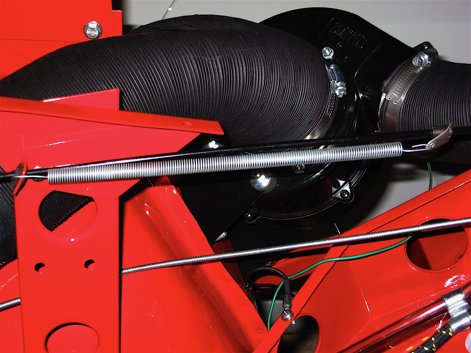
RH Fresh Air Hose to Blower
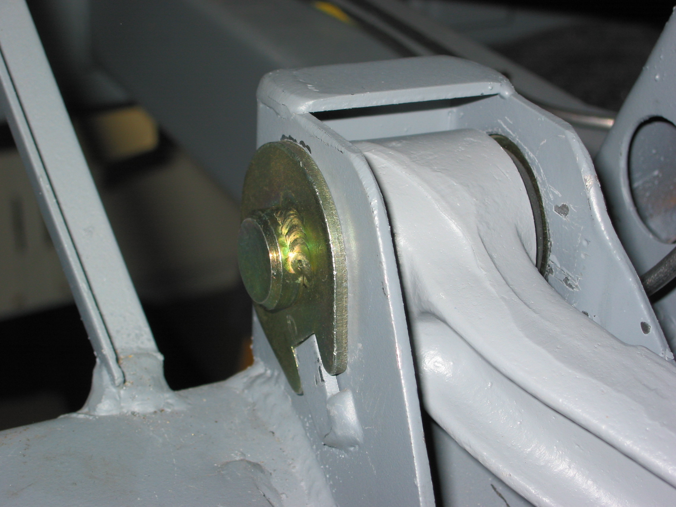
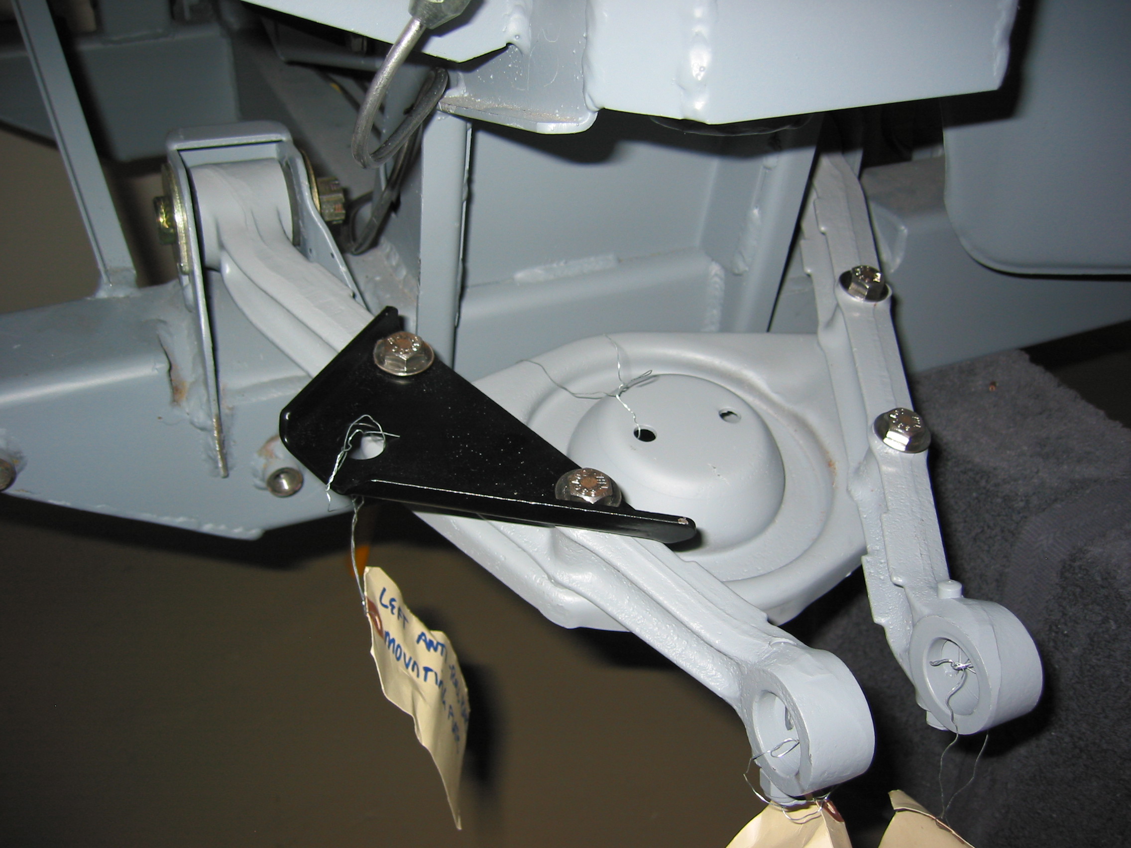
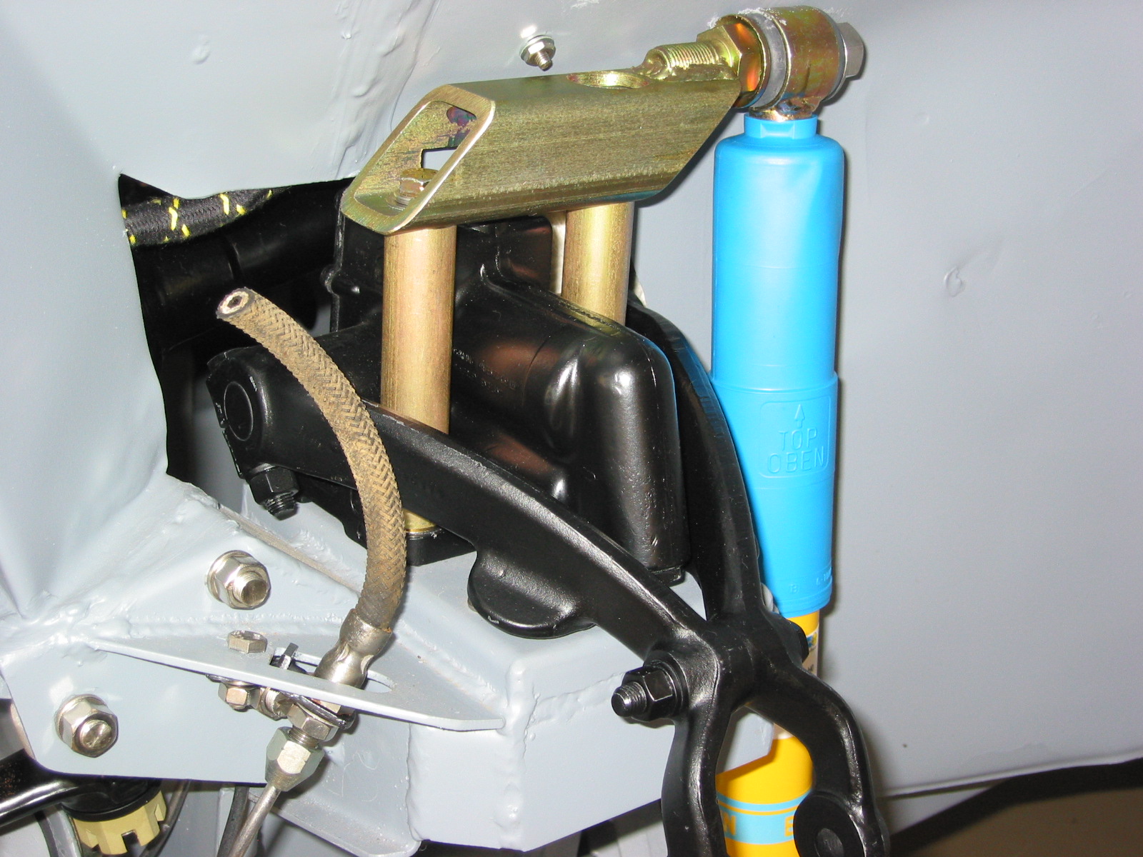
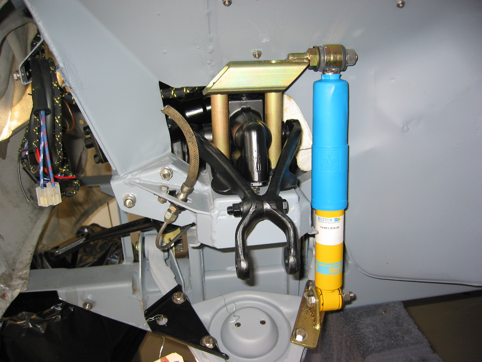
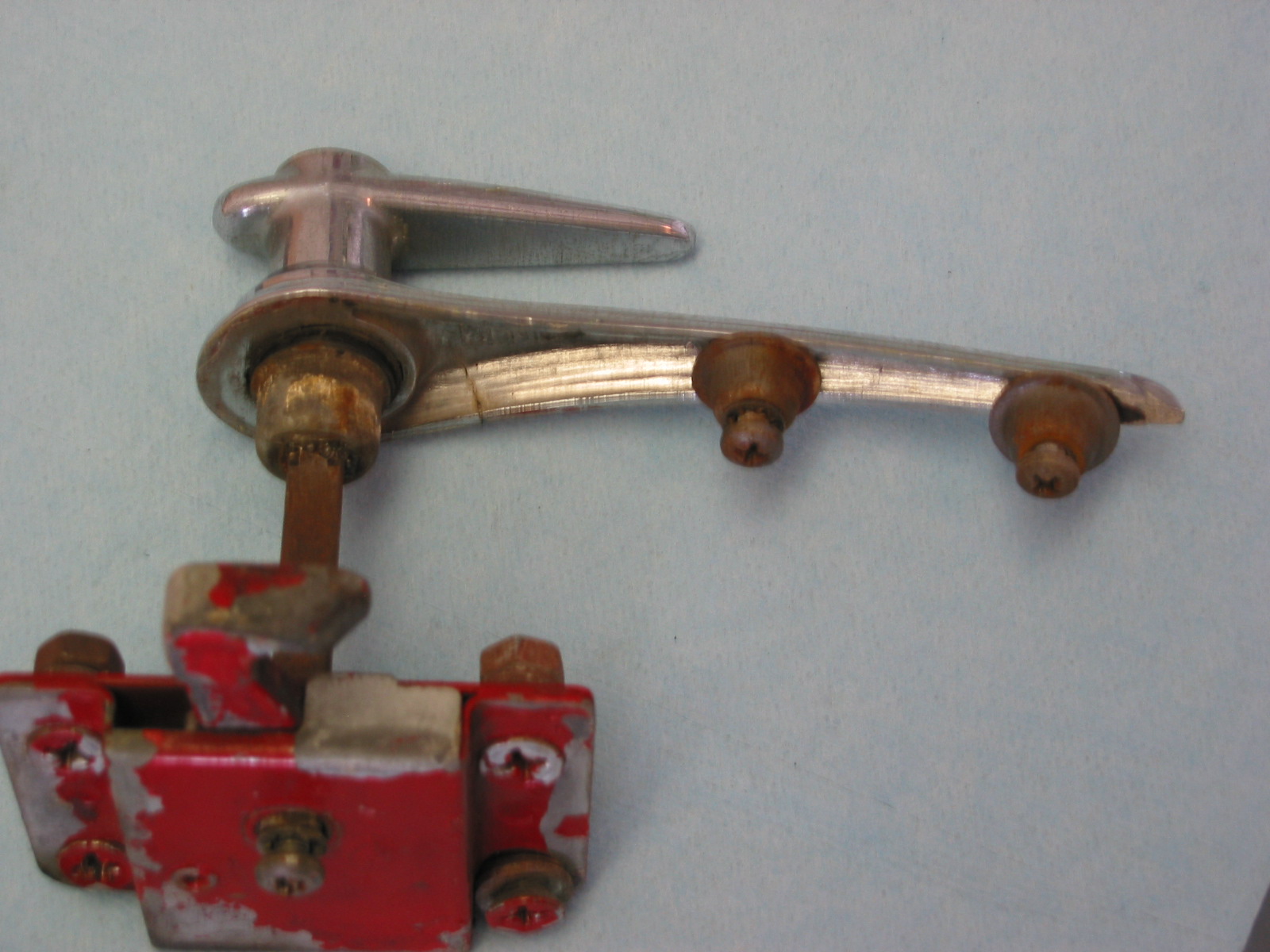
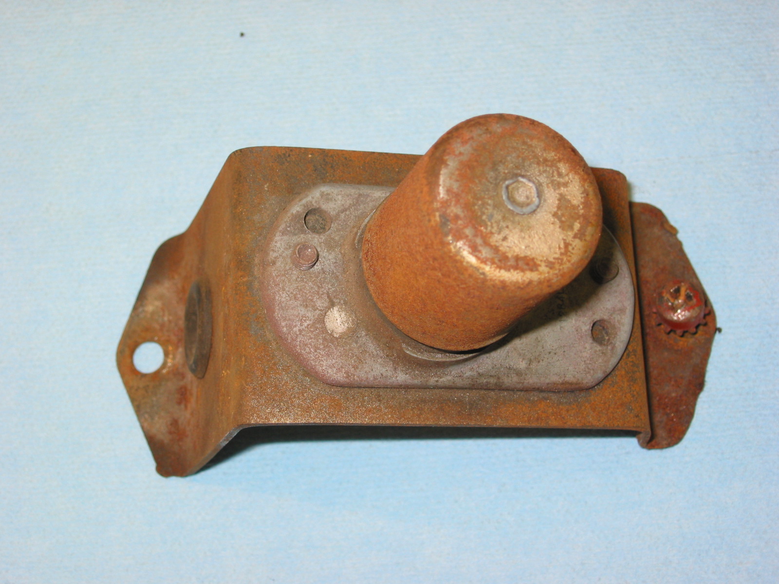
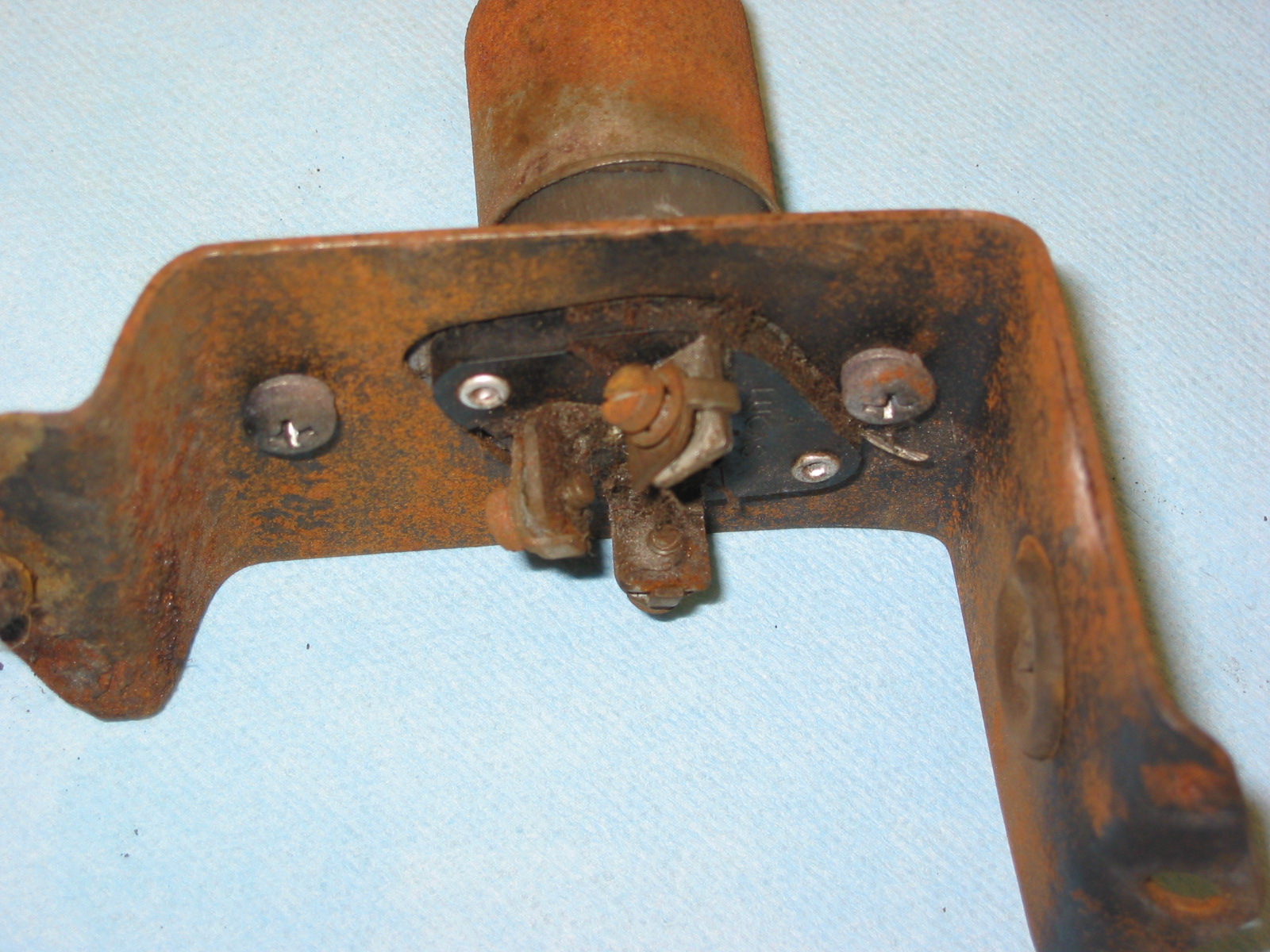
The bonnet catch lever and its connecting rod were then secured to the frame bracket with stainless split pins. Then the anti-rattle spring hardware was attached to the bonnet remote control rod.

Bonnet Catch Lever & Connecting Rod
Although the original equipping of the Healey did not provide for any type of screen for the front of the RH fresh air hose (other than the one in the heater blower), I purchased some plastic flexible screen and attached it to the hose with a clamp. This will hopefully keep bugs and small children out of the cooling system. Time will tell how this works.
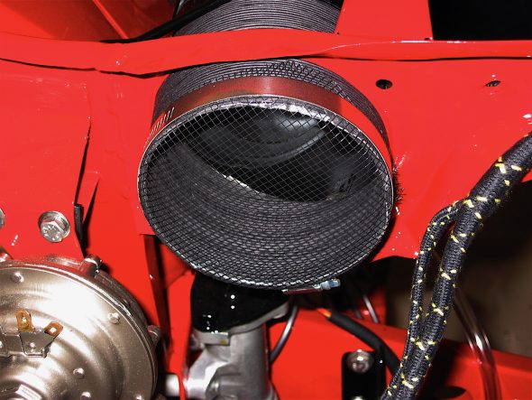
Screen for RH fresh air Hose
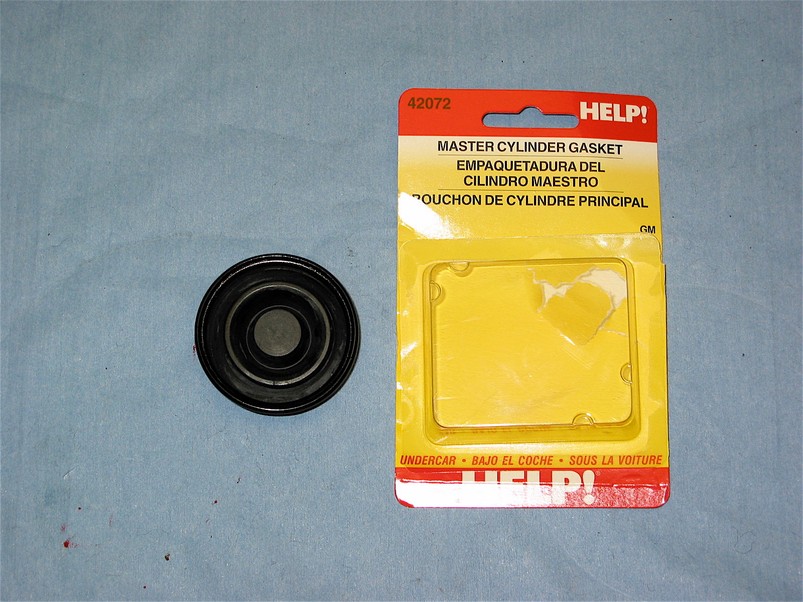
Adding fluids and lubrication was next on my list. Many on the email list had suggested using a HELP product #42072to replace the original rubber gasket in the brake reservoir cap to avoid brake fluid “spray” getting to the paint. I purchased and installed the gasket and it does fit perfectly and provides a nice tight seal to the canister.

HELP # 42072 diaphragm gasket
I then proceeded to purge the air from the brake and clutch lines by bleeding the system. It is not that this job is hard, but I hate it! Brake fluid is messy stuff and paint does not like it.
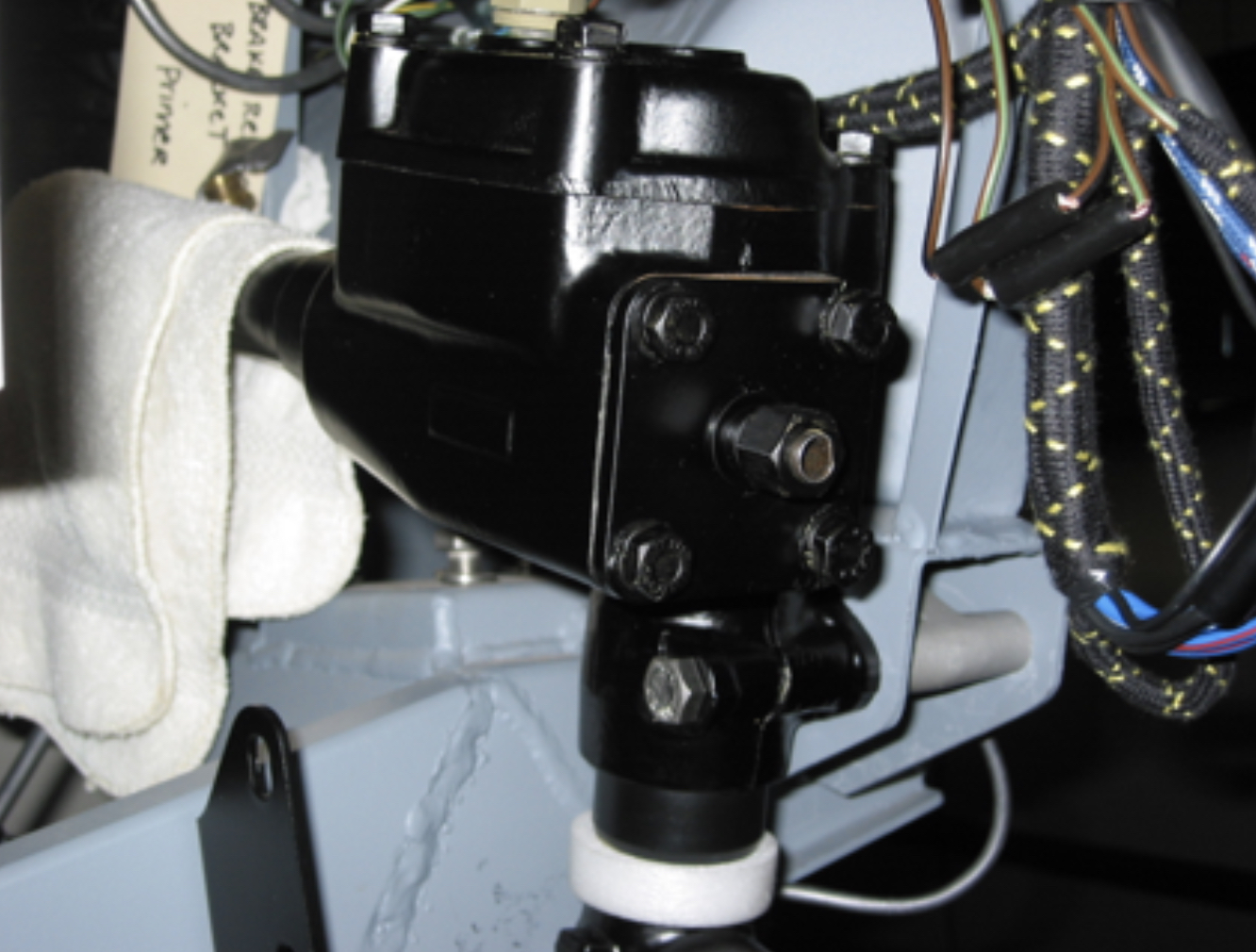
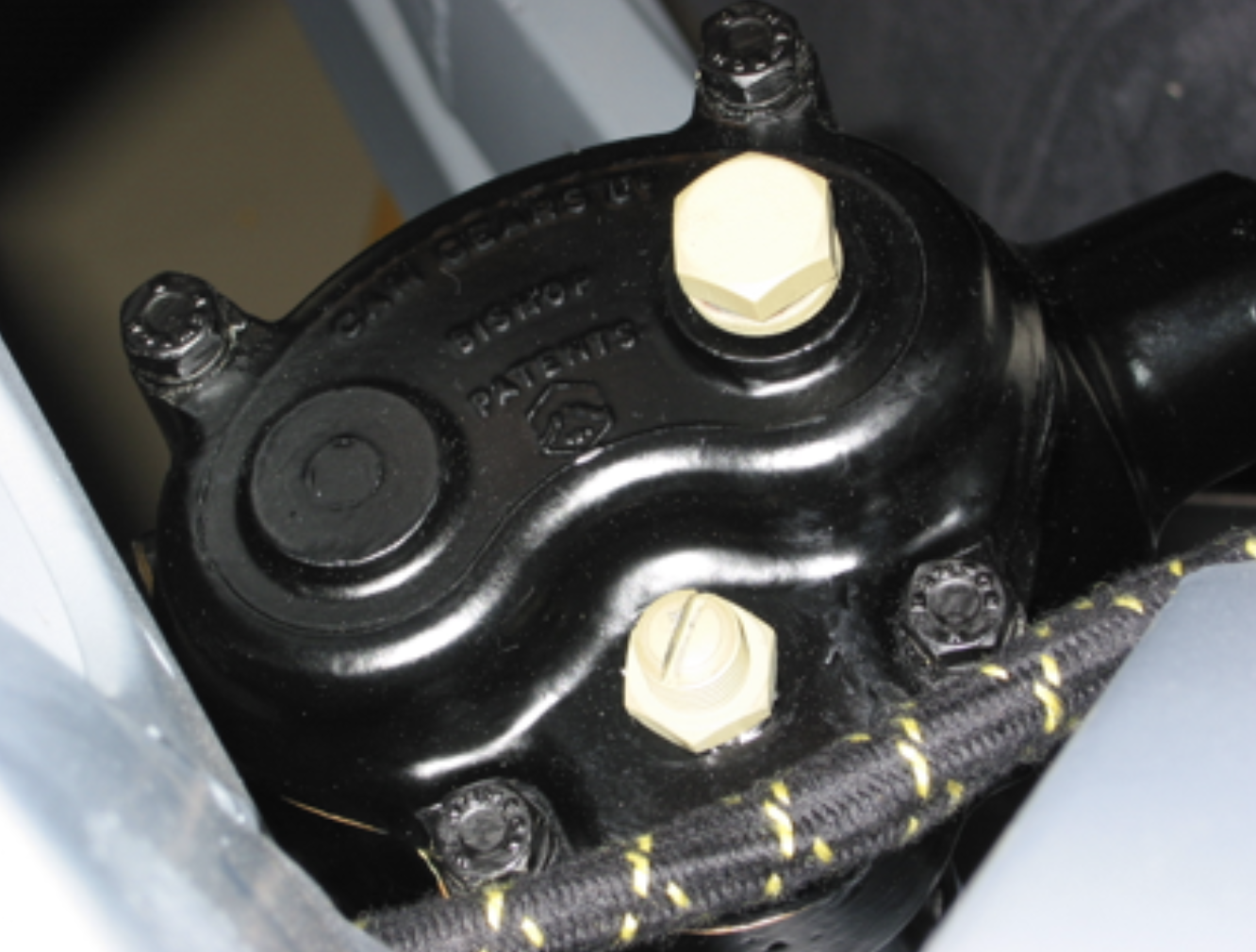
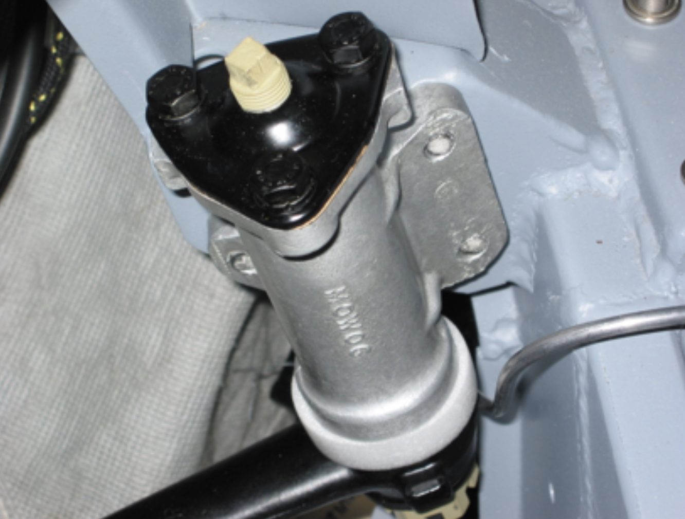
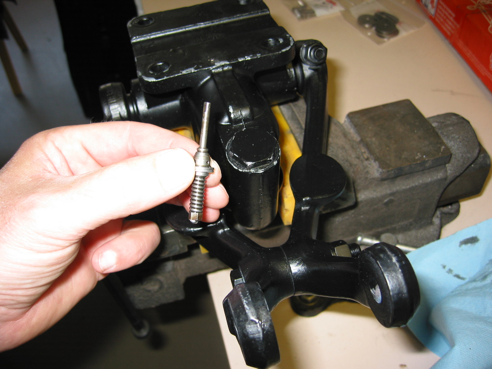
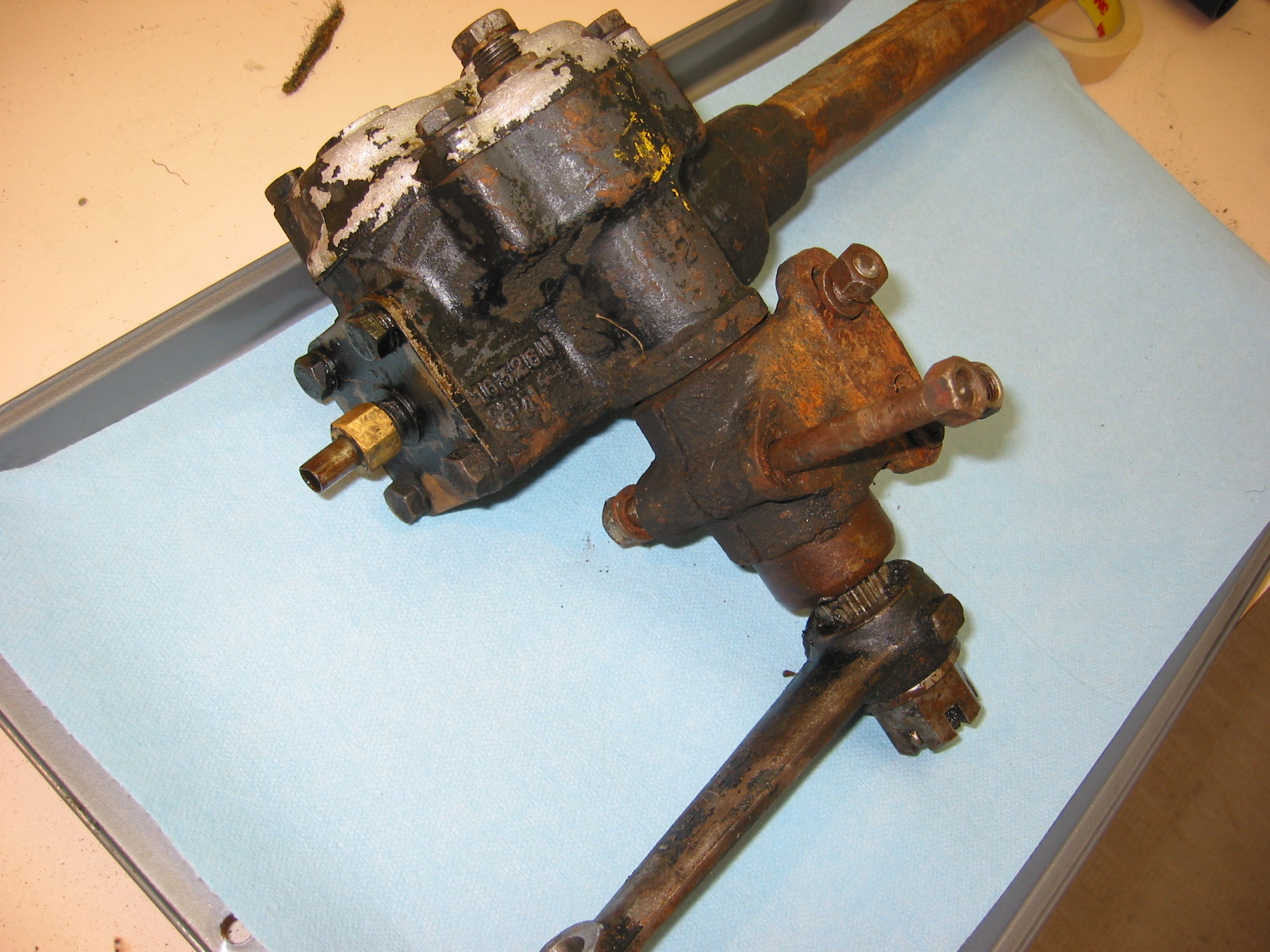
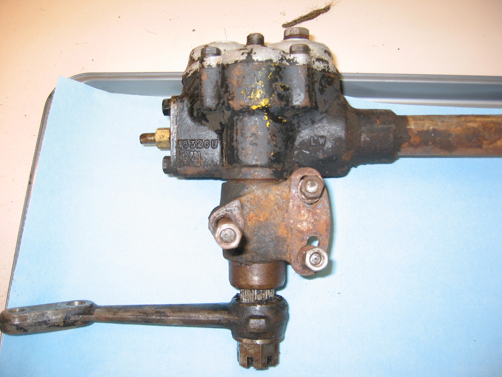
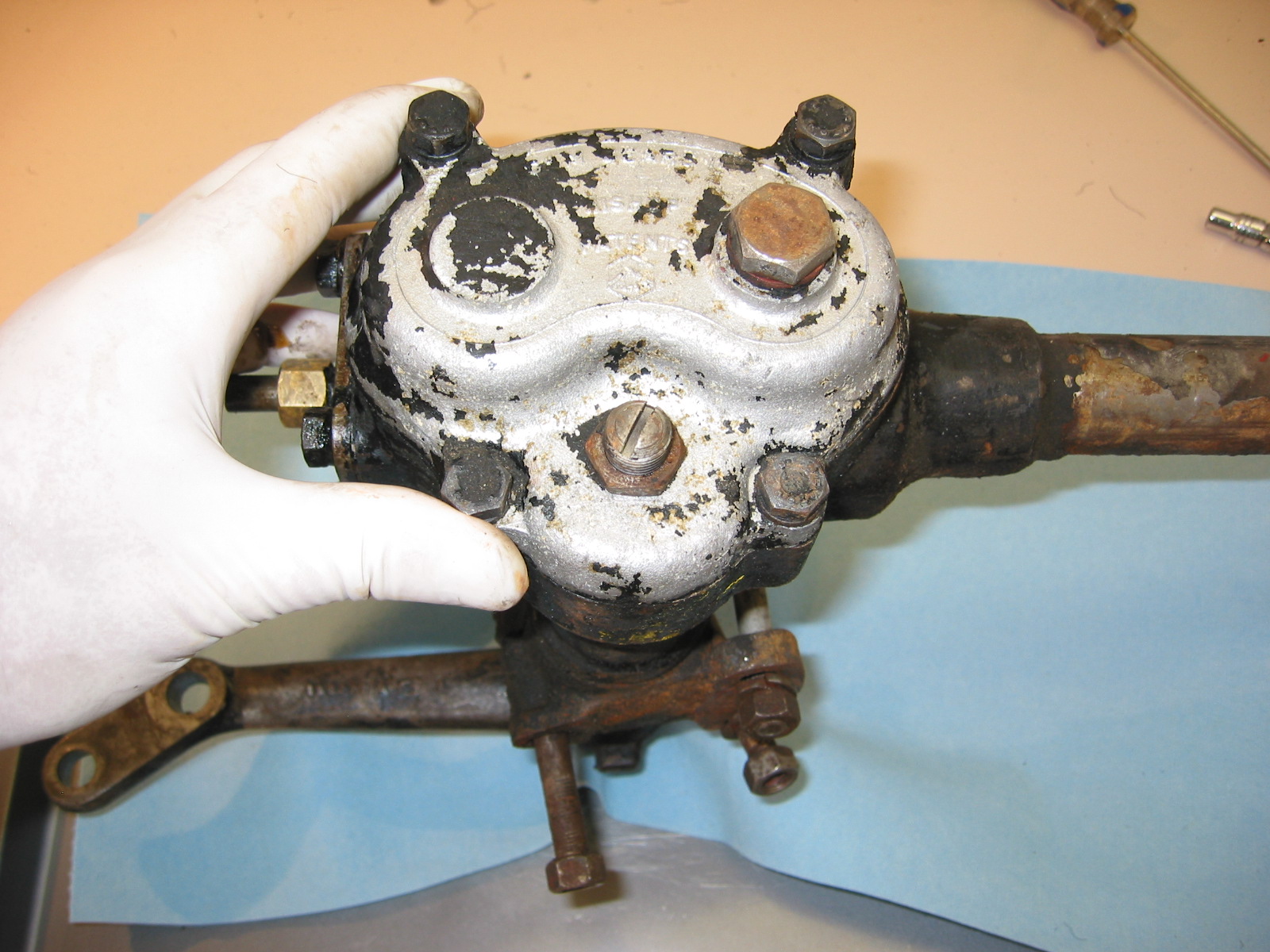
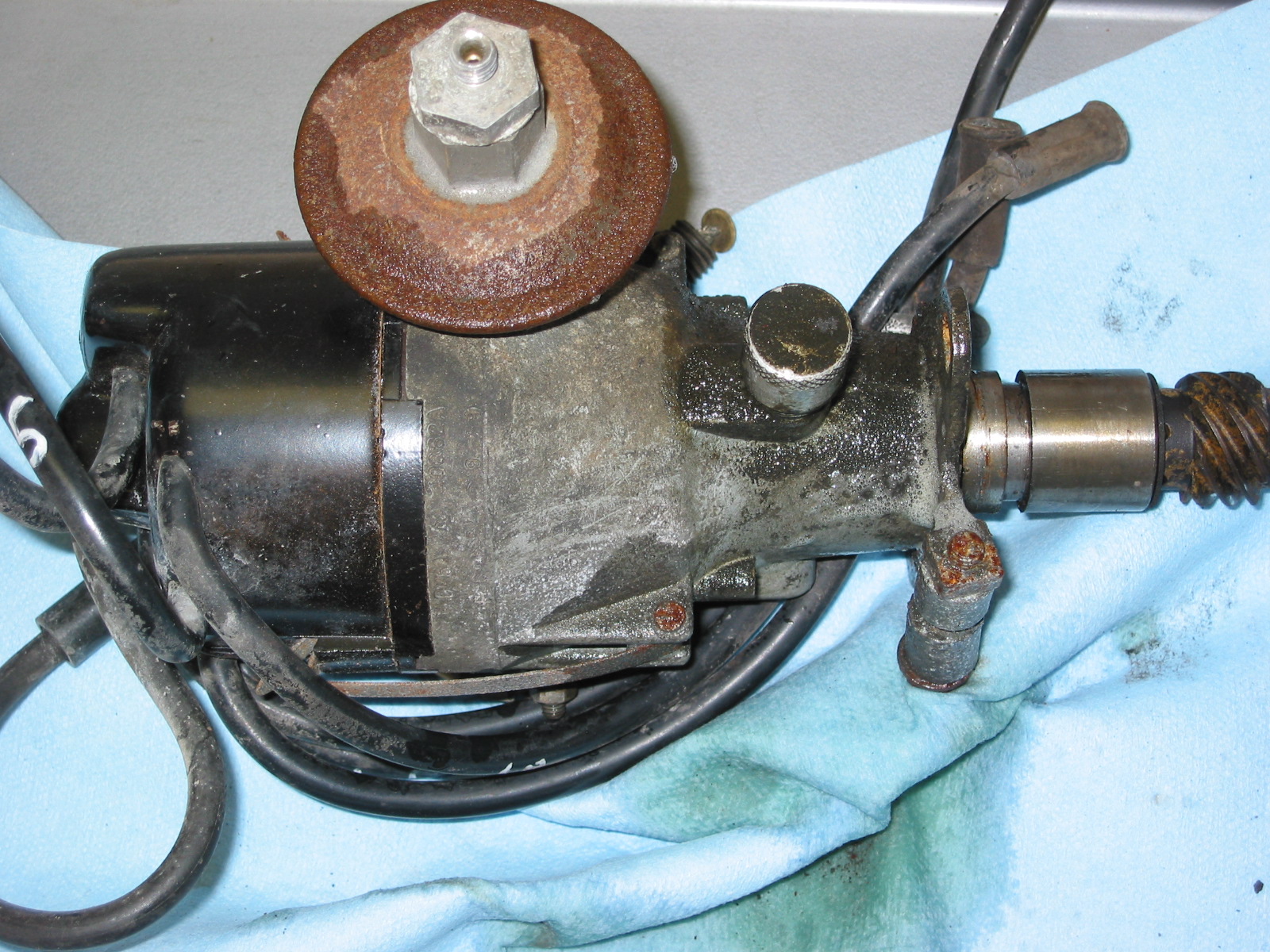
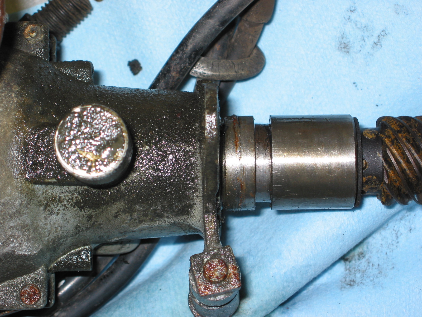
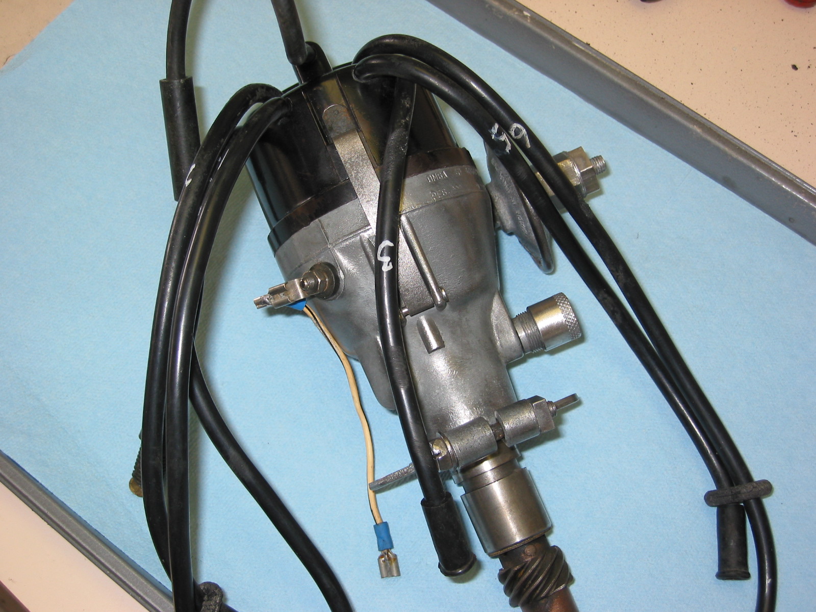
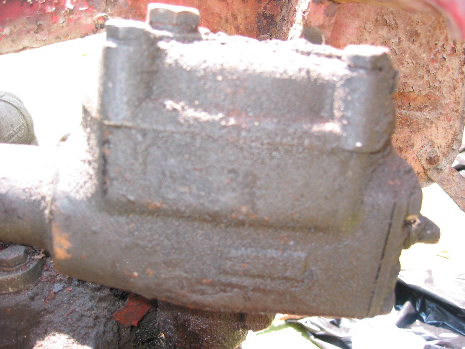
Bruce at Healey Surgeons had added steering lube to the idler when he rebuilt it, but now was time to add the lube for the steering box. I used Penrite Steering Box Lube. It is thick stuff. I set the plastic container in a pot of boiling water for a while to heat it up and therefore “thin” it. The container comes with a very handy applicator tube that fit right in the steering box hole. I filled it up and then tightened the fill nut. No leaks the next morning!
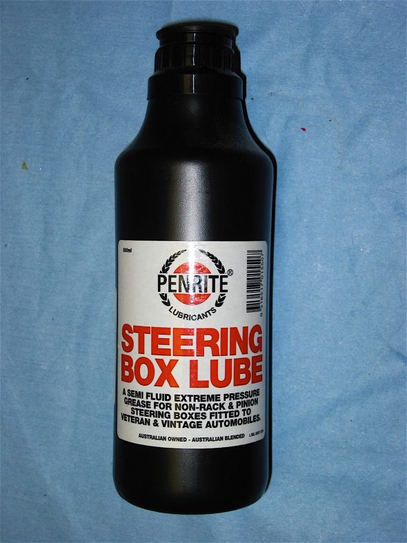
Penrite Steering Box Lube
I found out the hard way that filling the rear axle with gear lube would have been easier prior to installing the rear seats, but with the aid of a clear plastic tube I was able to get 3.6 pints of Valvoline 90 weight gear lube into the rear differential.