We sent our custom made wiring harness to Rhode Island Wiring Services to have the harness covered with a cloth braid using a royal blue double tracer. The cost was $5.25 per foot with an $8.00 machine set-up fee. We were very pleased with the results. Pardon the messy work bench – it gets that way from time to time!
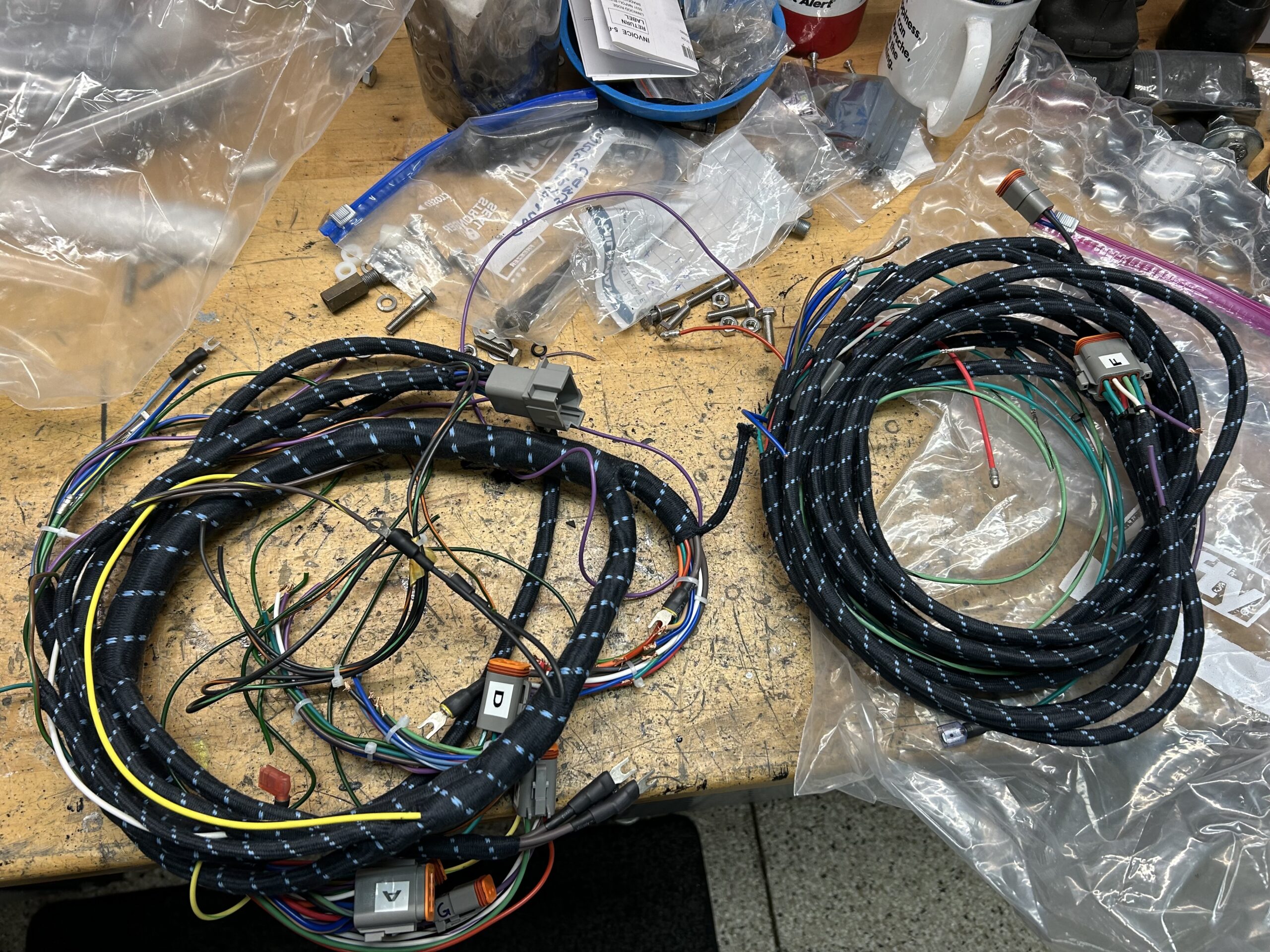
Cloth Braided Wiring Harness
Previous posts cover the creation and circuit testing of the harness:
A new electrical system – https://valvechatter.com/?p=13986
Building and Testing the New Wiring Harness – https://valvechatter.com/?p=14061
JWR Bugeye Wiring Diagrams: https://valvechatter.com/?p=14067
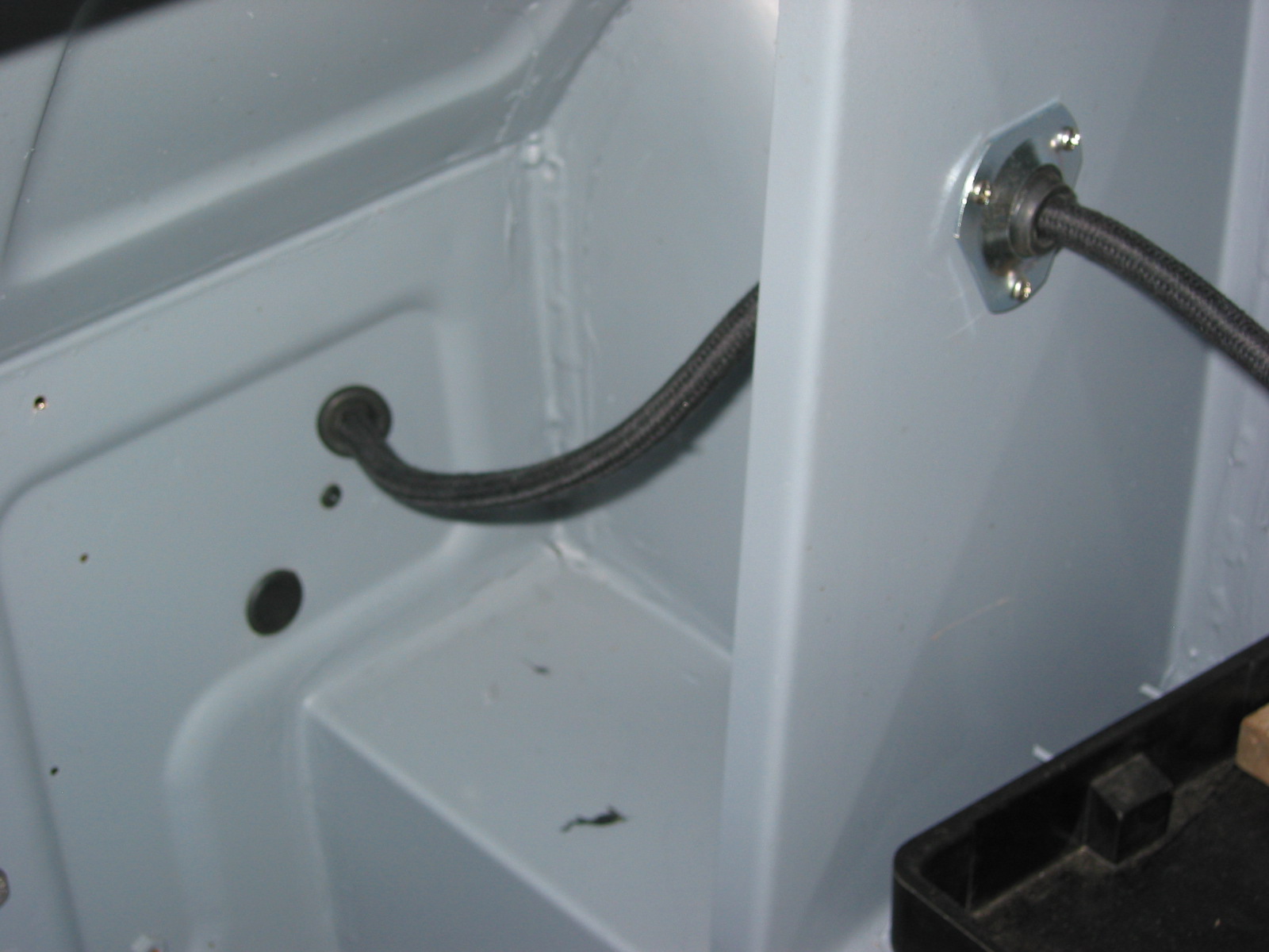
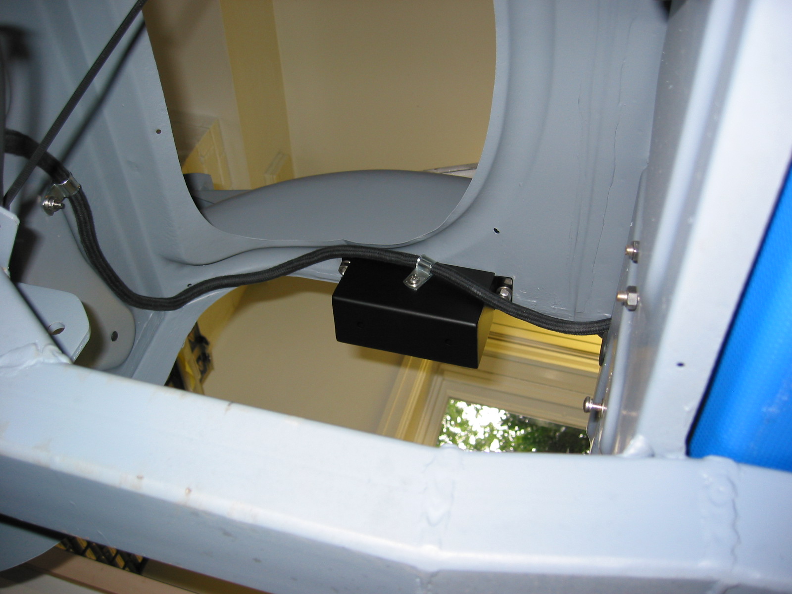
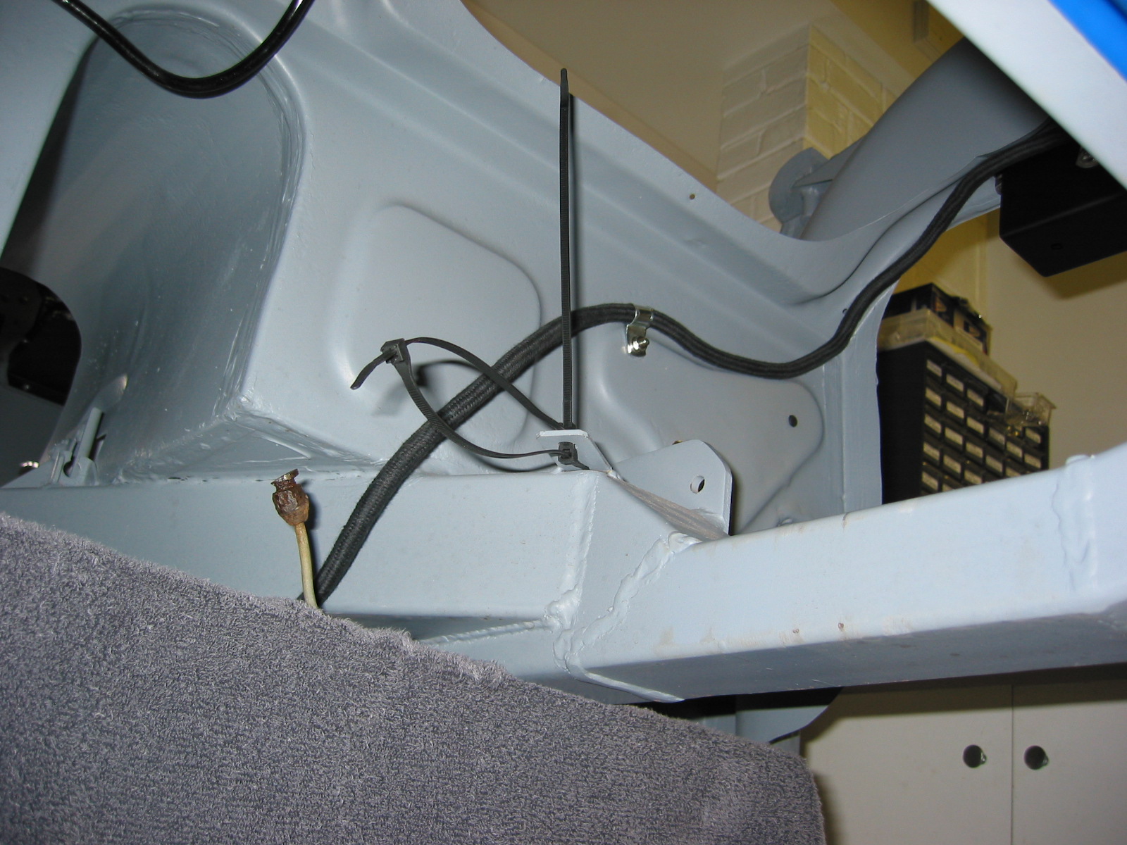
Finally, the time has arrived to install the harness in the car. The first step was to get the end of the harness though the firewall grommet. Not easy with the Deutsch connectors attached, but we got them through.
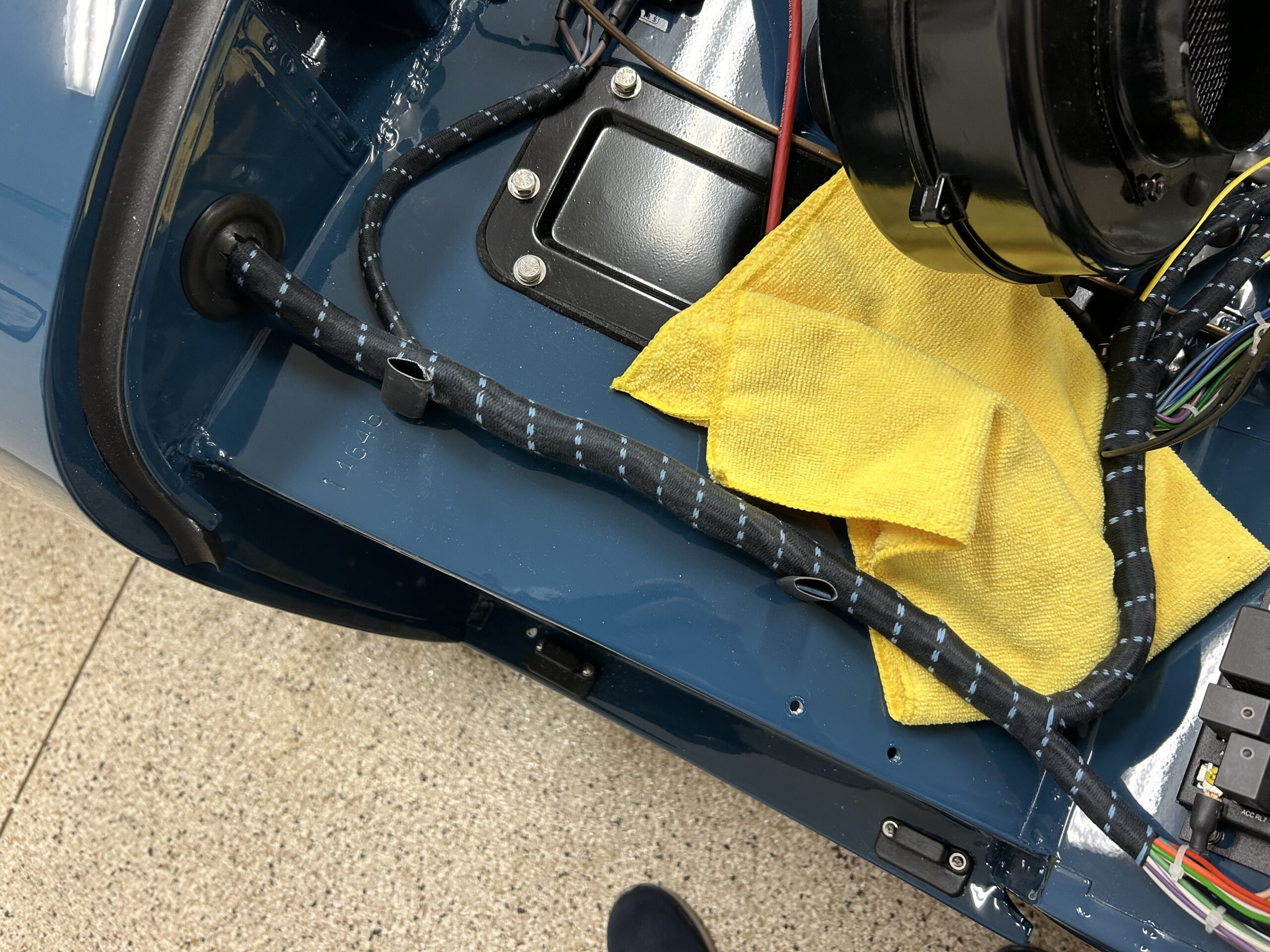
Harness through the firewall grommet
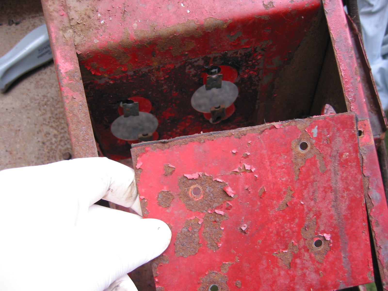
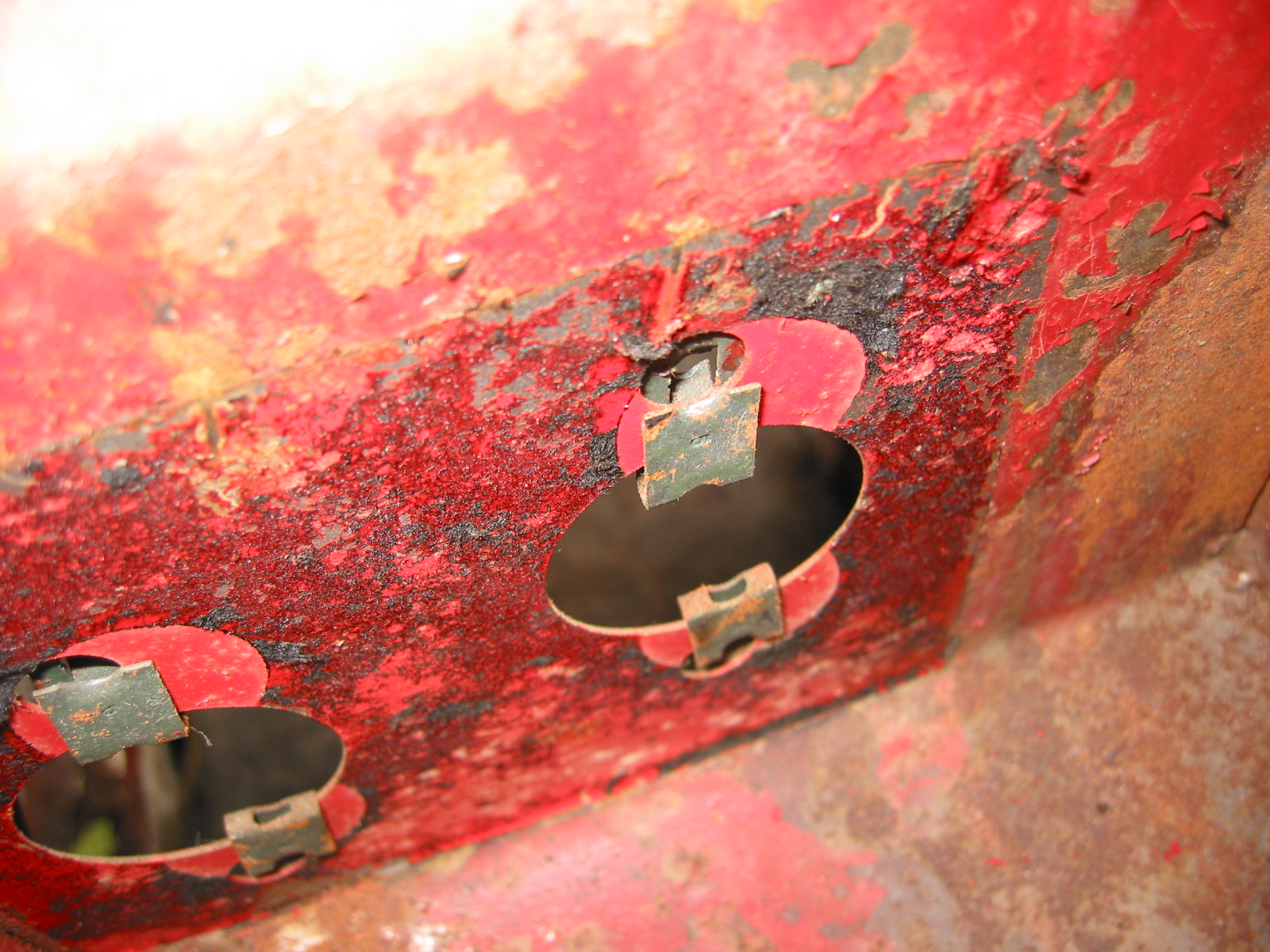
The next step was to connect the three wires in the harness to the small power supply fuse box. One thirty amp wire feeds the Ignition bank in the fuse box, the other thirty amp wire feeds the accessory bank in the fuse box and the fifteen amp wire feeds the lights bank in the fuse box.
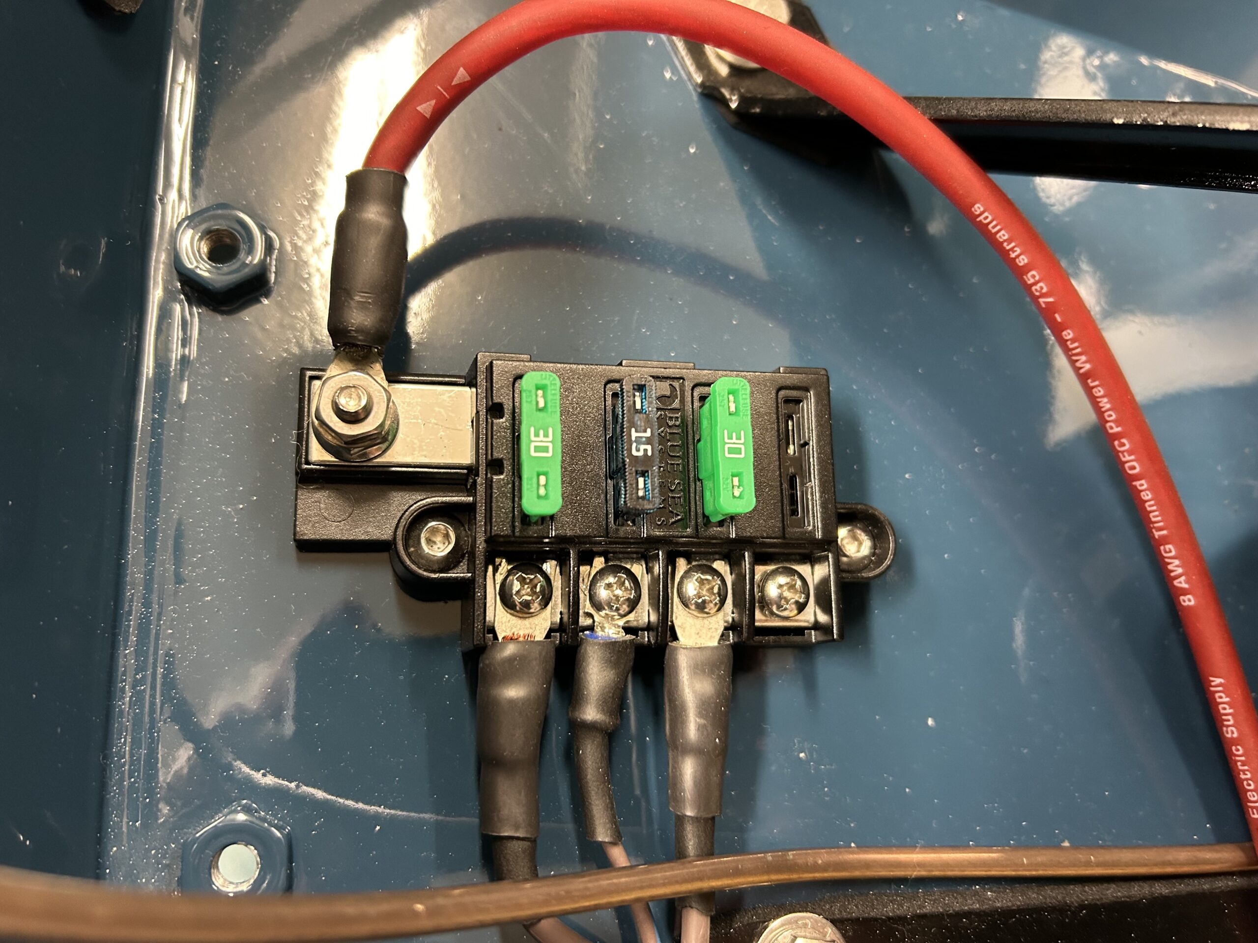
Power supply fuse box
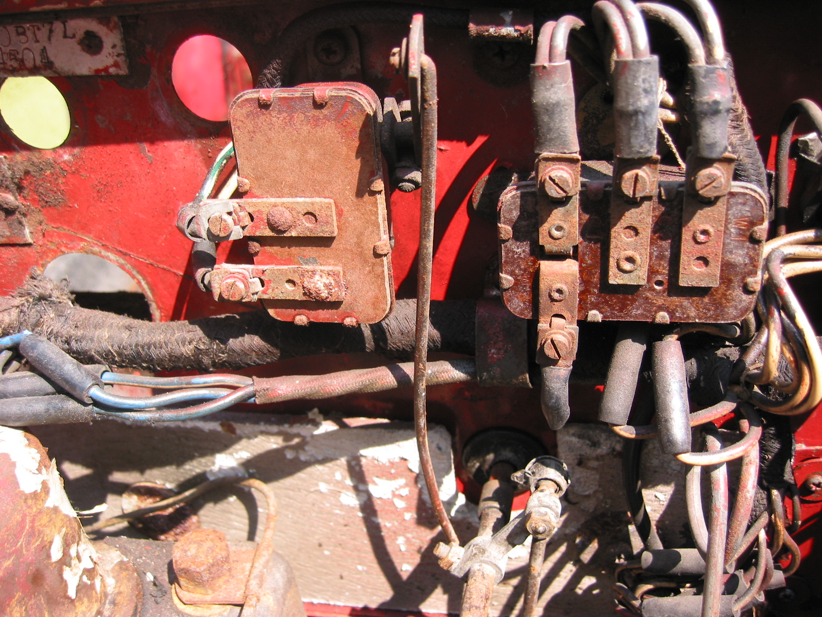
Then it was a matter of connecting the wires to the four banks of fused terminal positions in the Classic Technologies relay/fuse box.
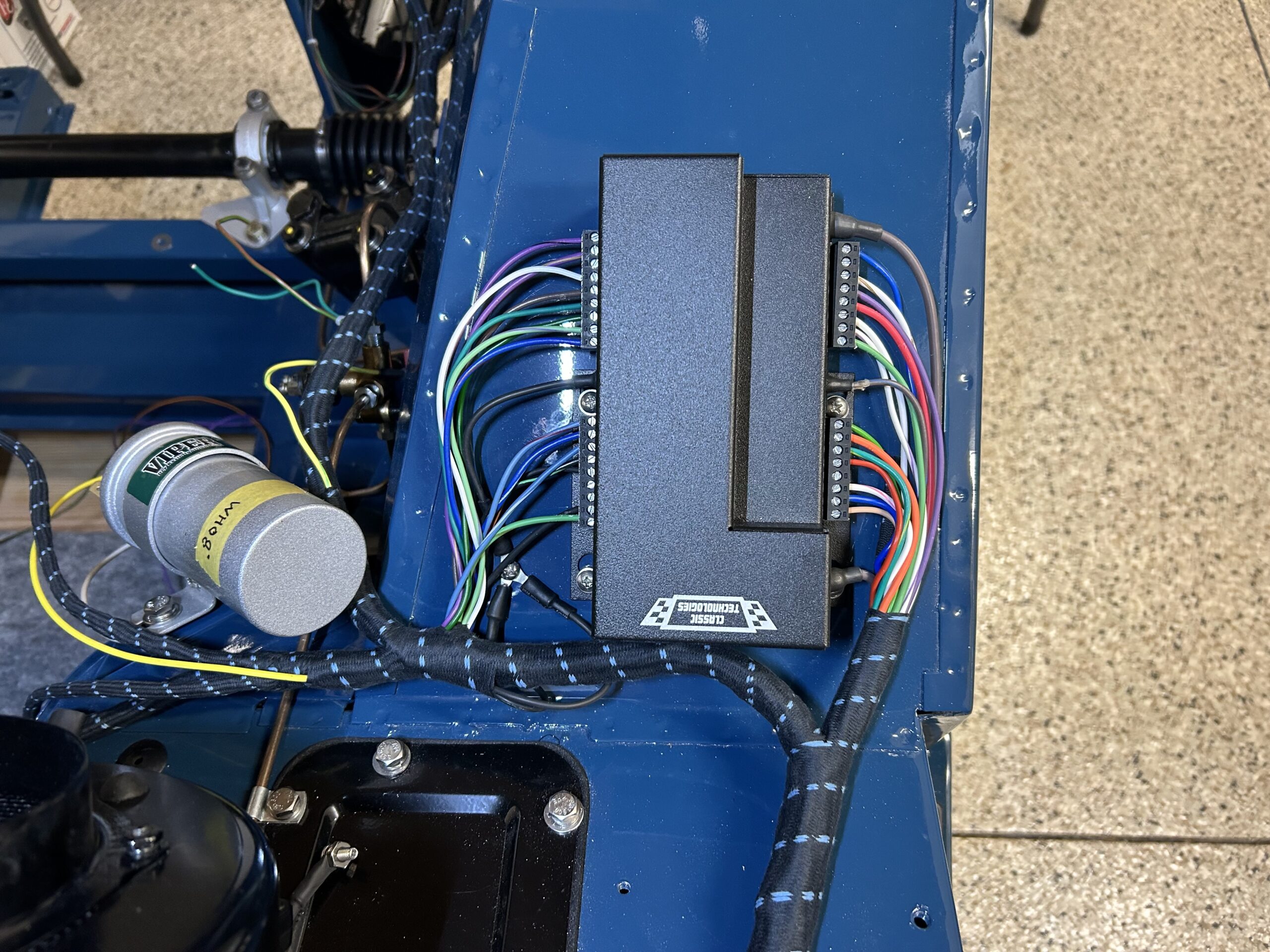
Fuse Box Wiring
We pulled all of the fuses in the two fuse boxes and will add them back one at a time as we test the circuits upon final installation.
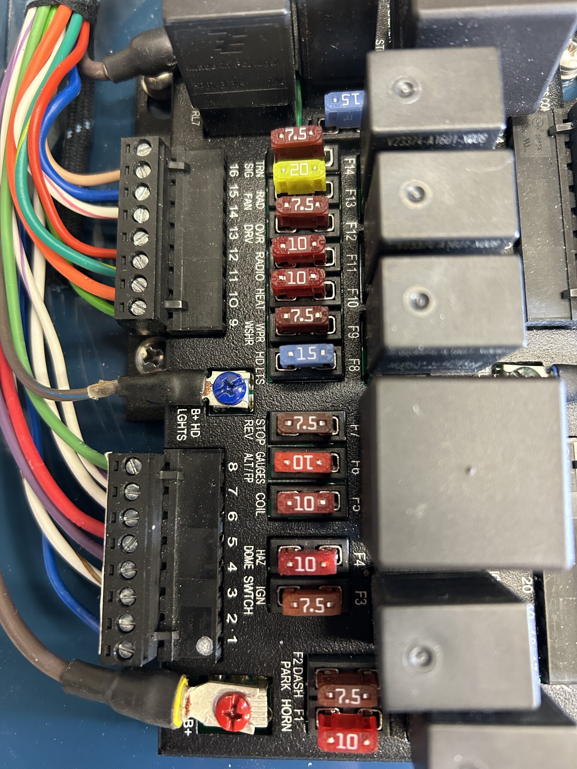
fuse installation with ratings
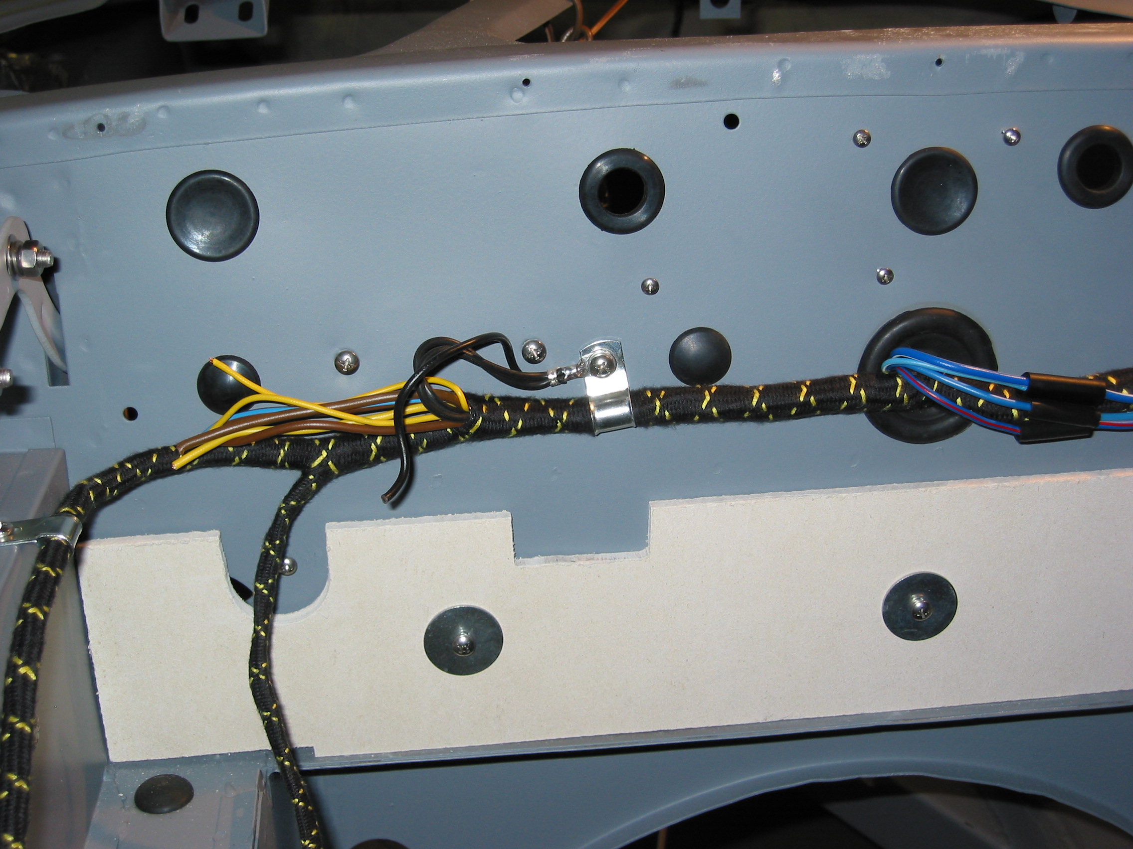
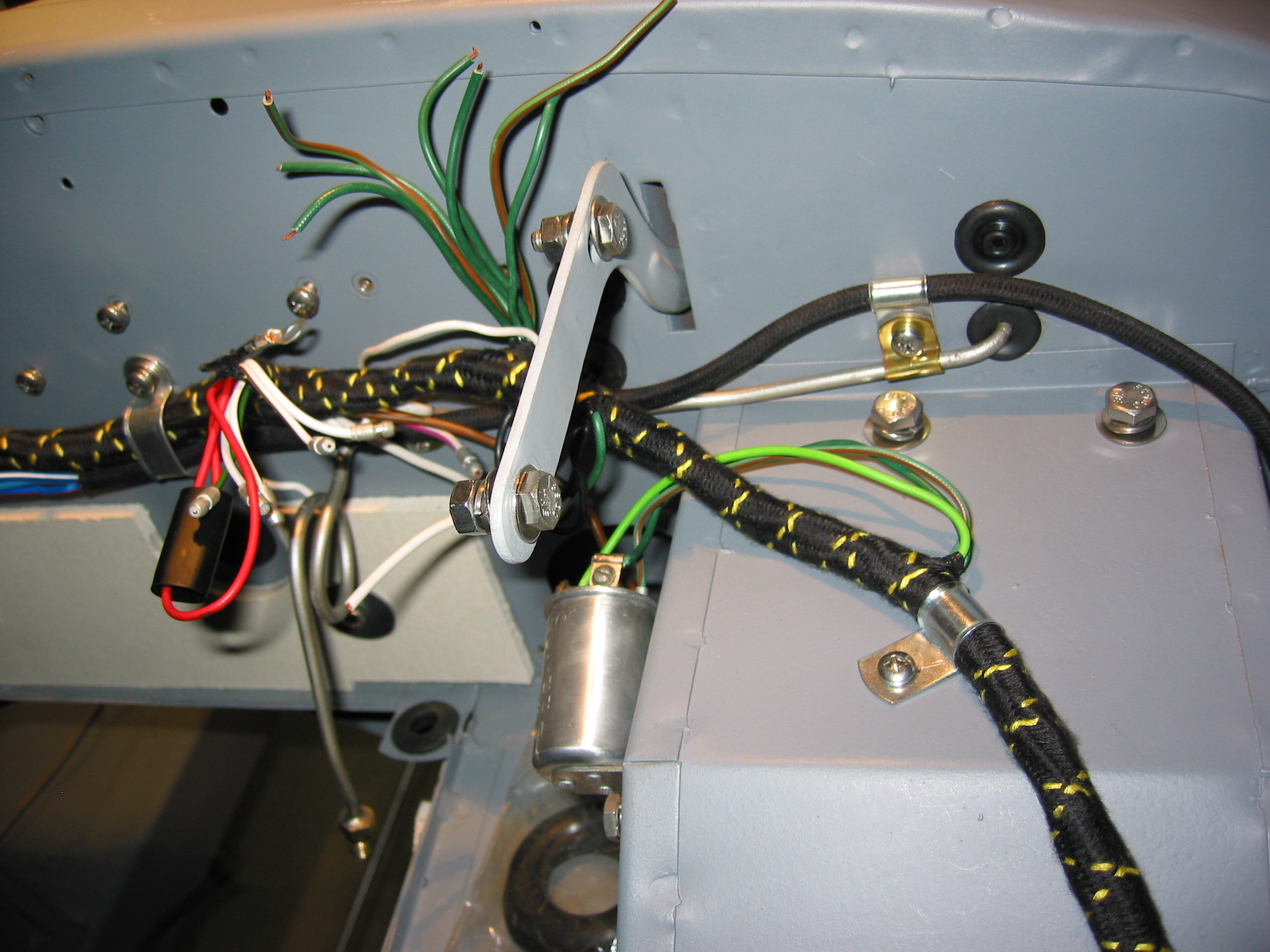
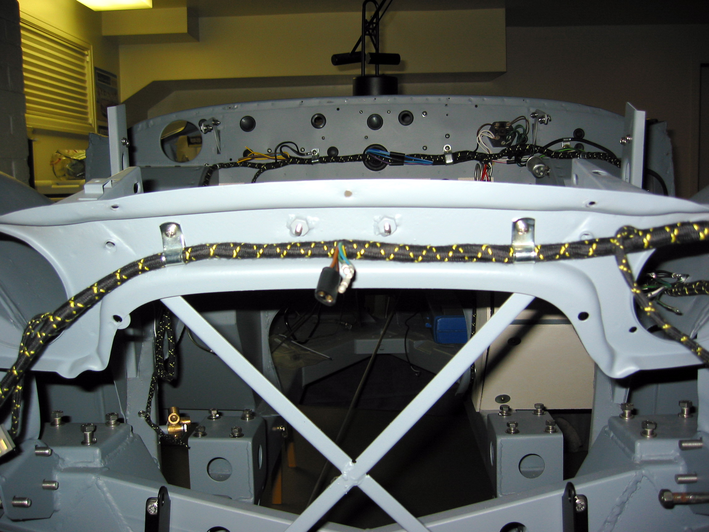
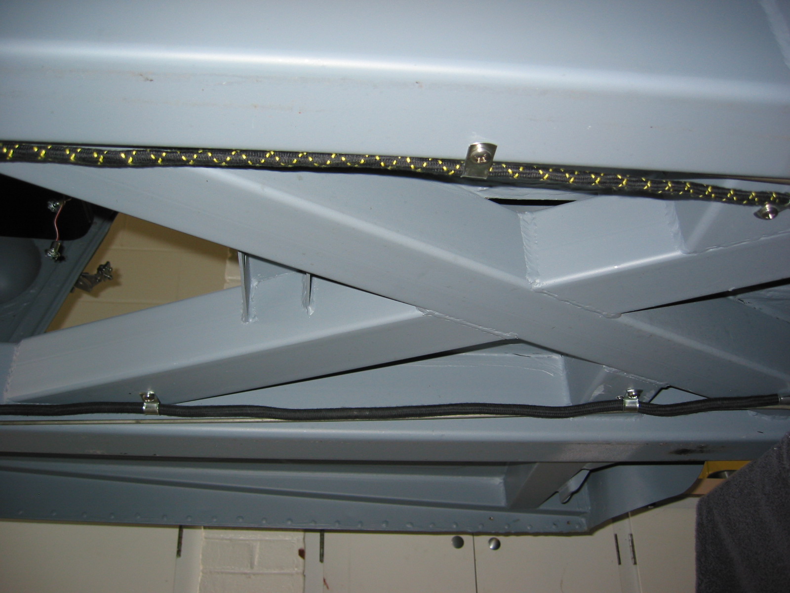
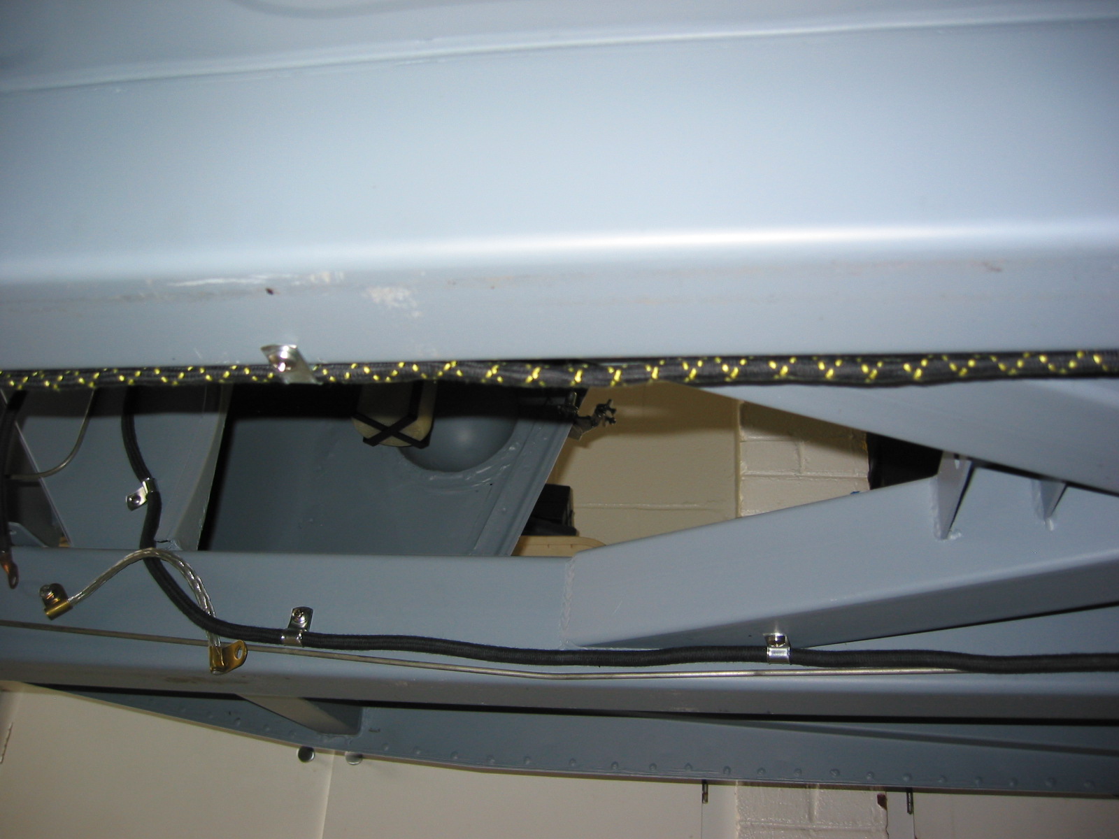
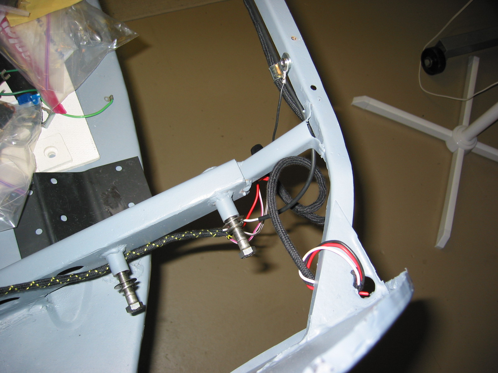
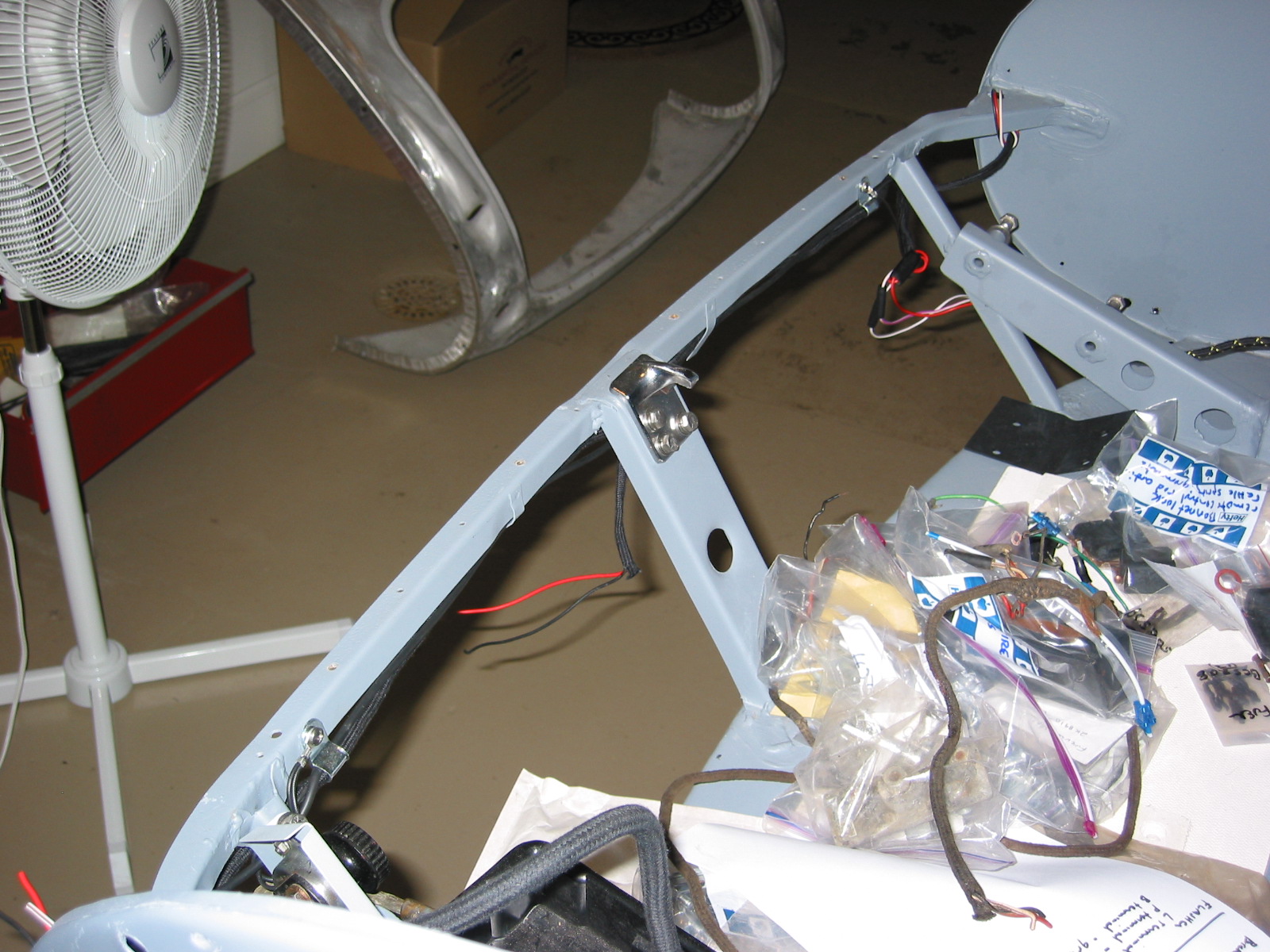
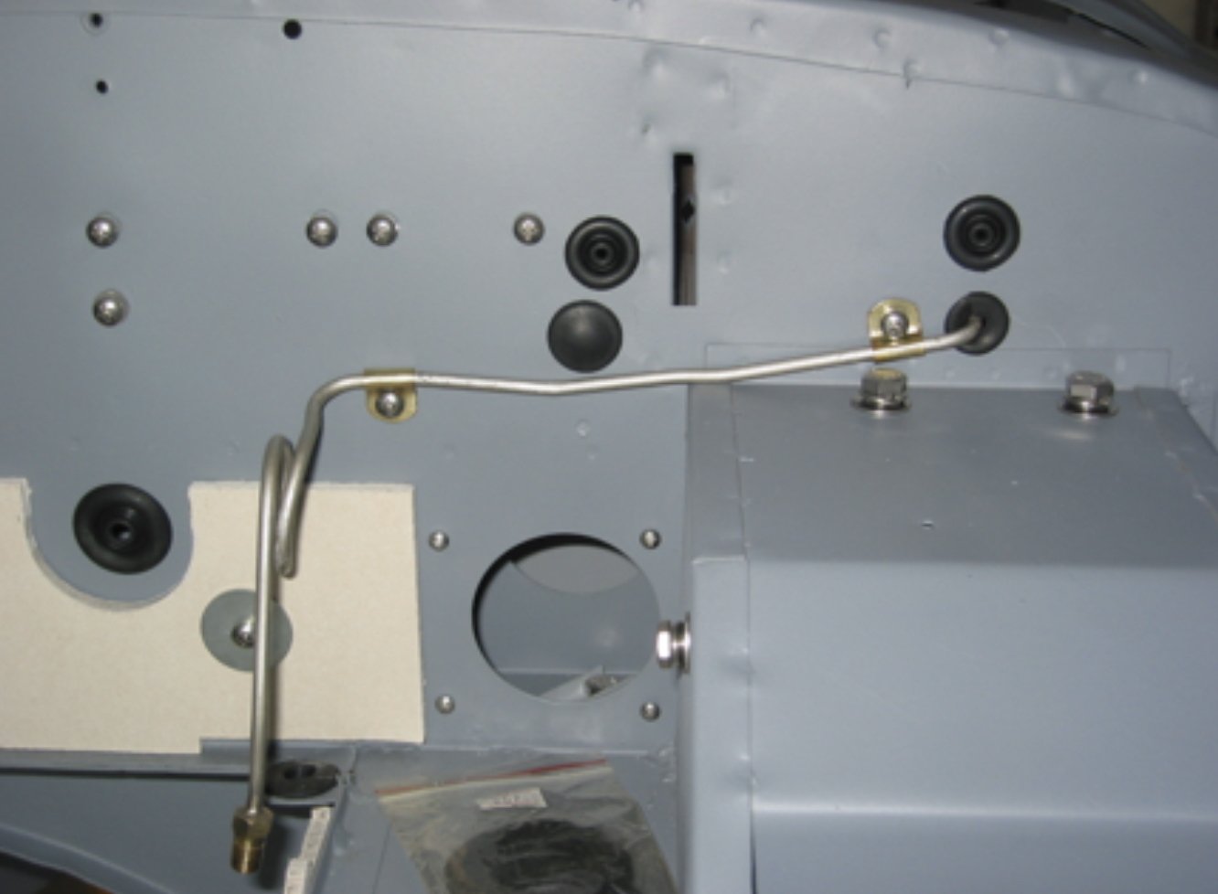
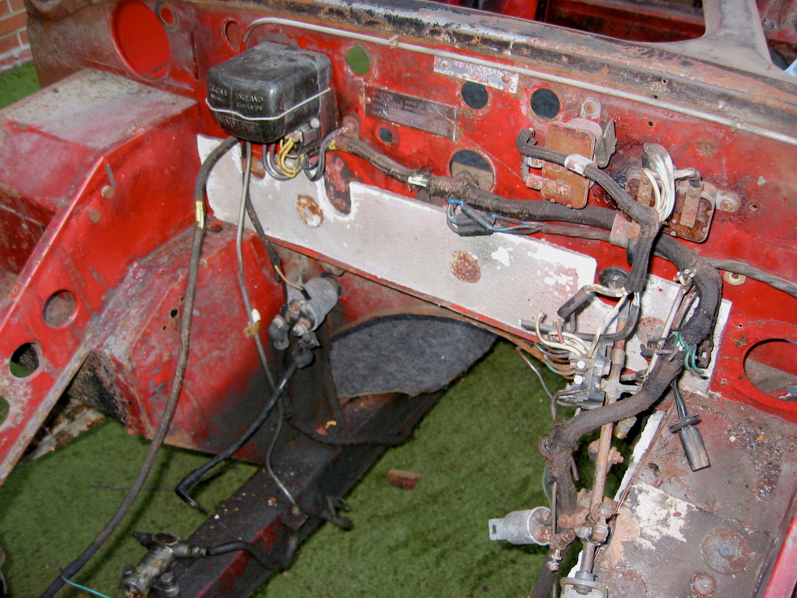
Next, we turned to the group of wires that run to the front of the car along the RH valance. Wiring for the coil, the hydraulic brake switch, the radiator fan, the radiator fan thermostat, the horns and the lights are in this bundle.
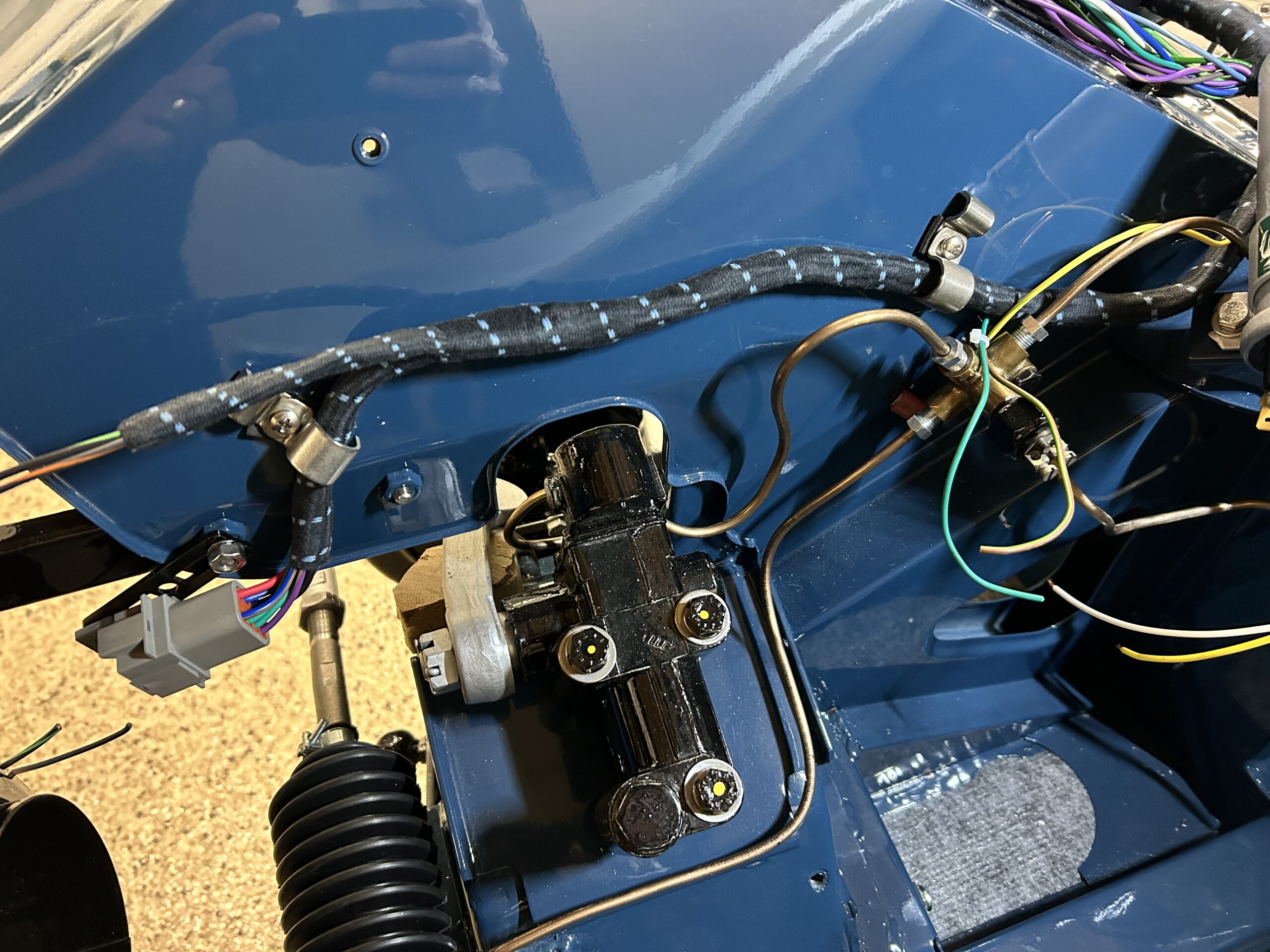
Wiring harness on RH Valance
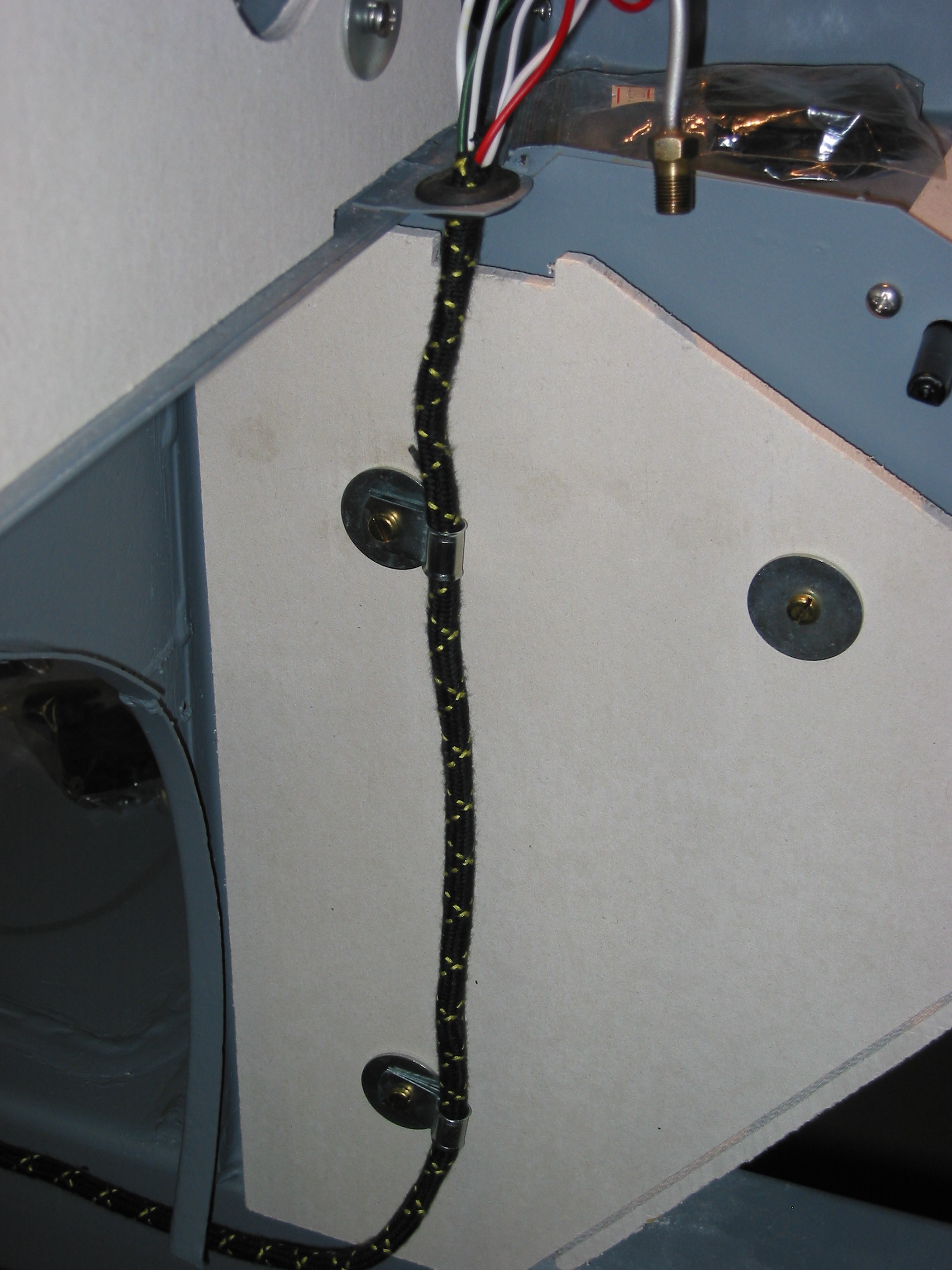
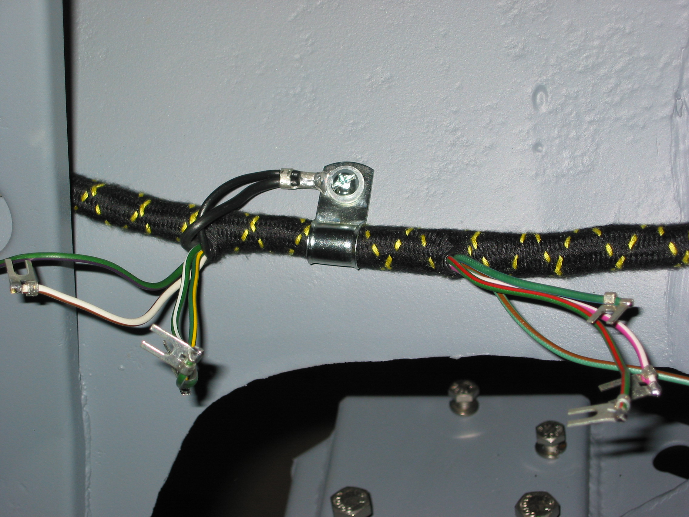
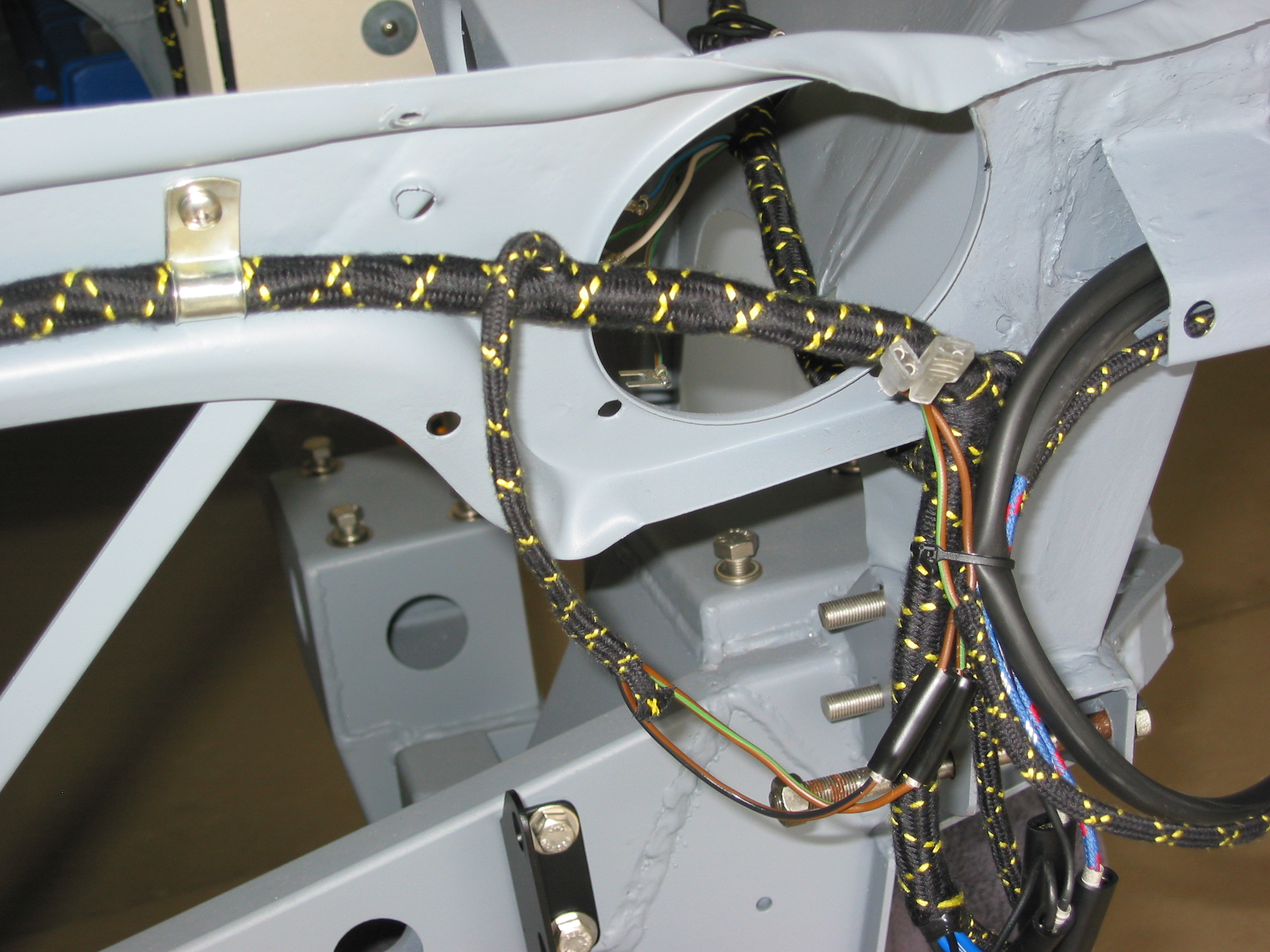
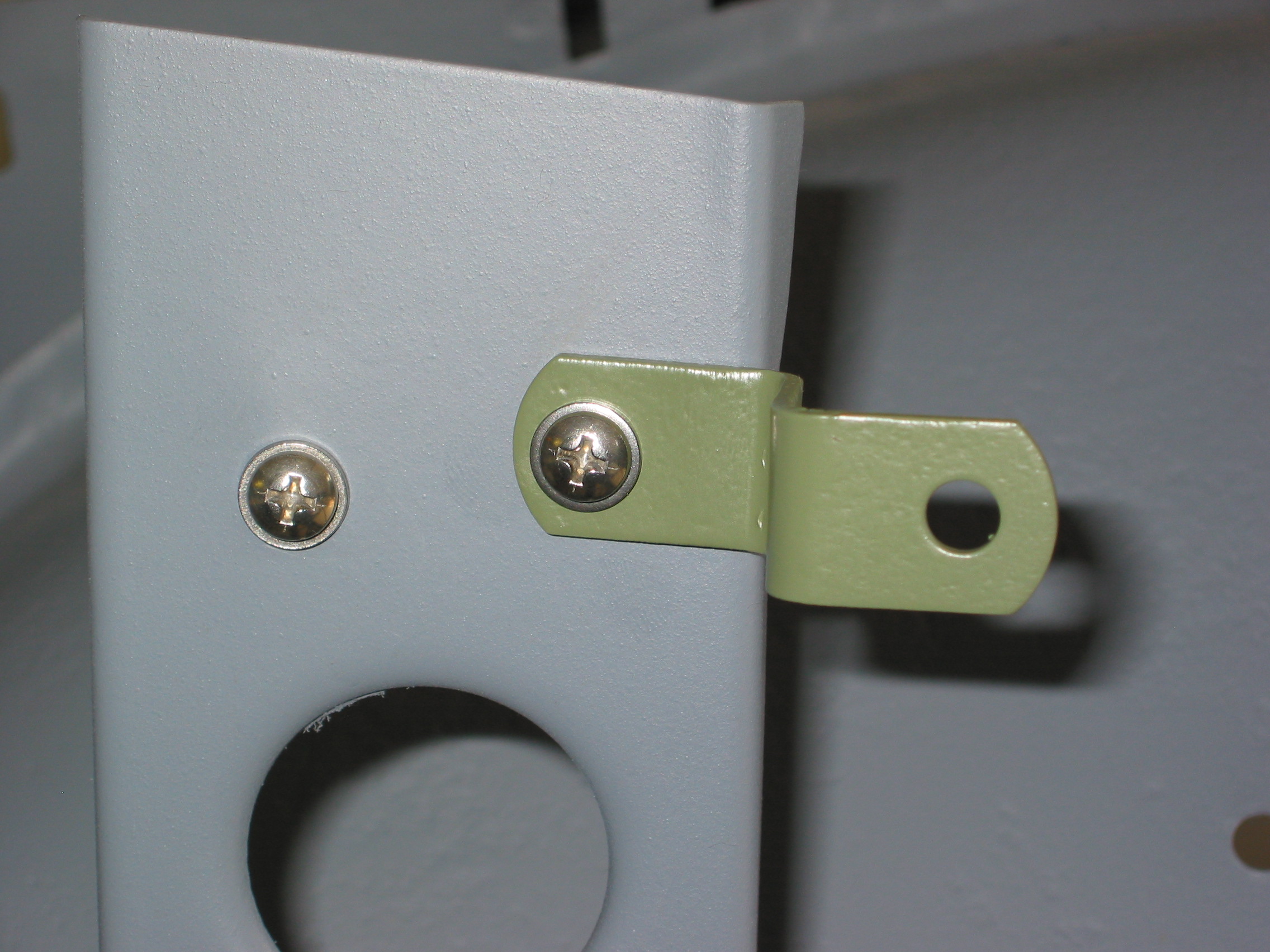
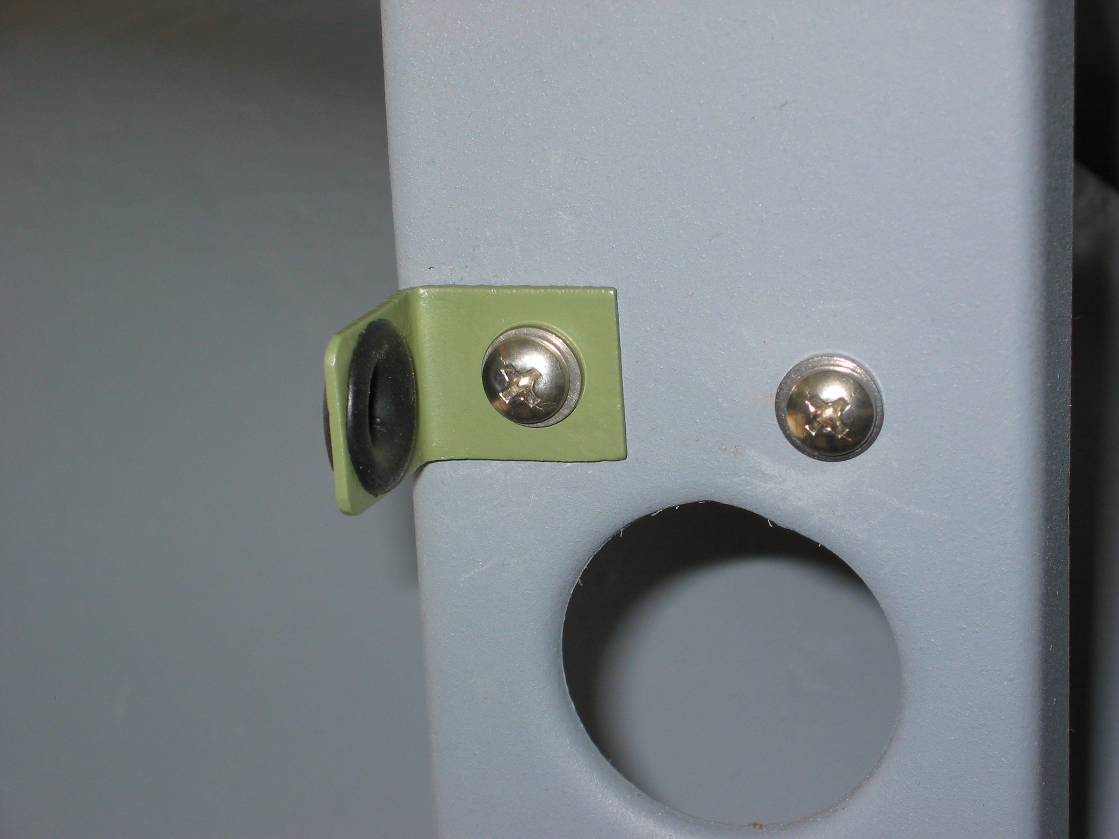
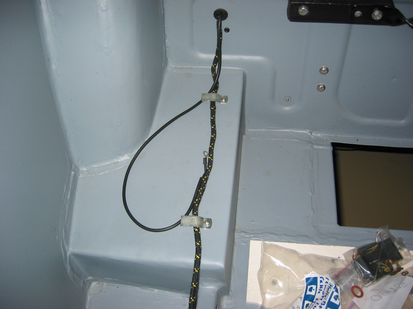
We used stainless steel clips to secure the wires to the valance. A smaller 3/8″ clip will be used to route the capillary tube for the water temperature gauge and sensor.
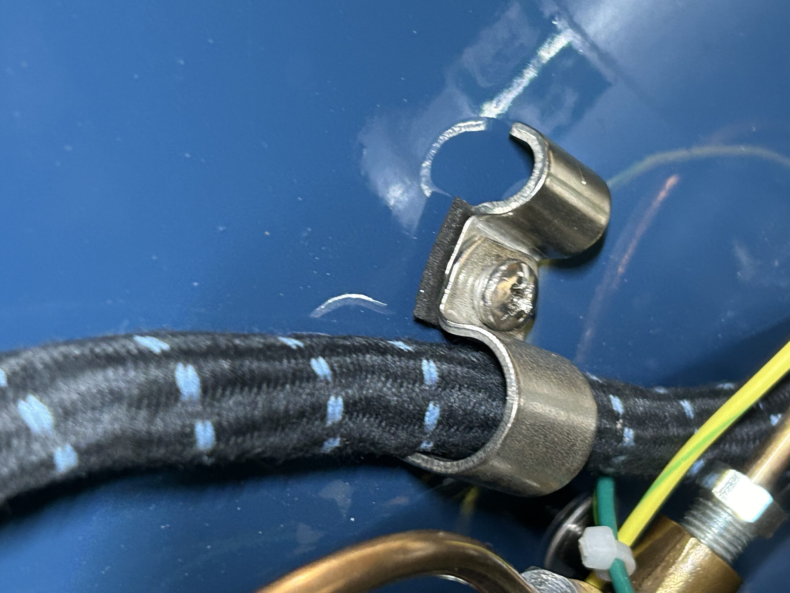
Stainless steel wiring clips
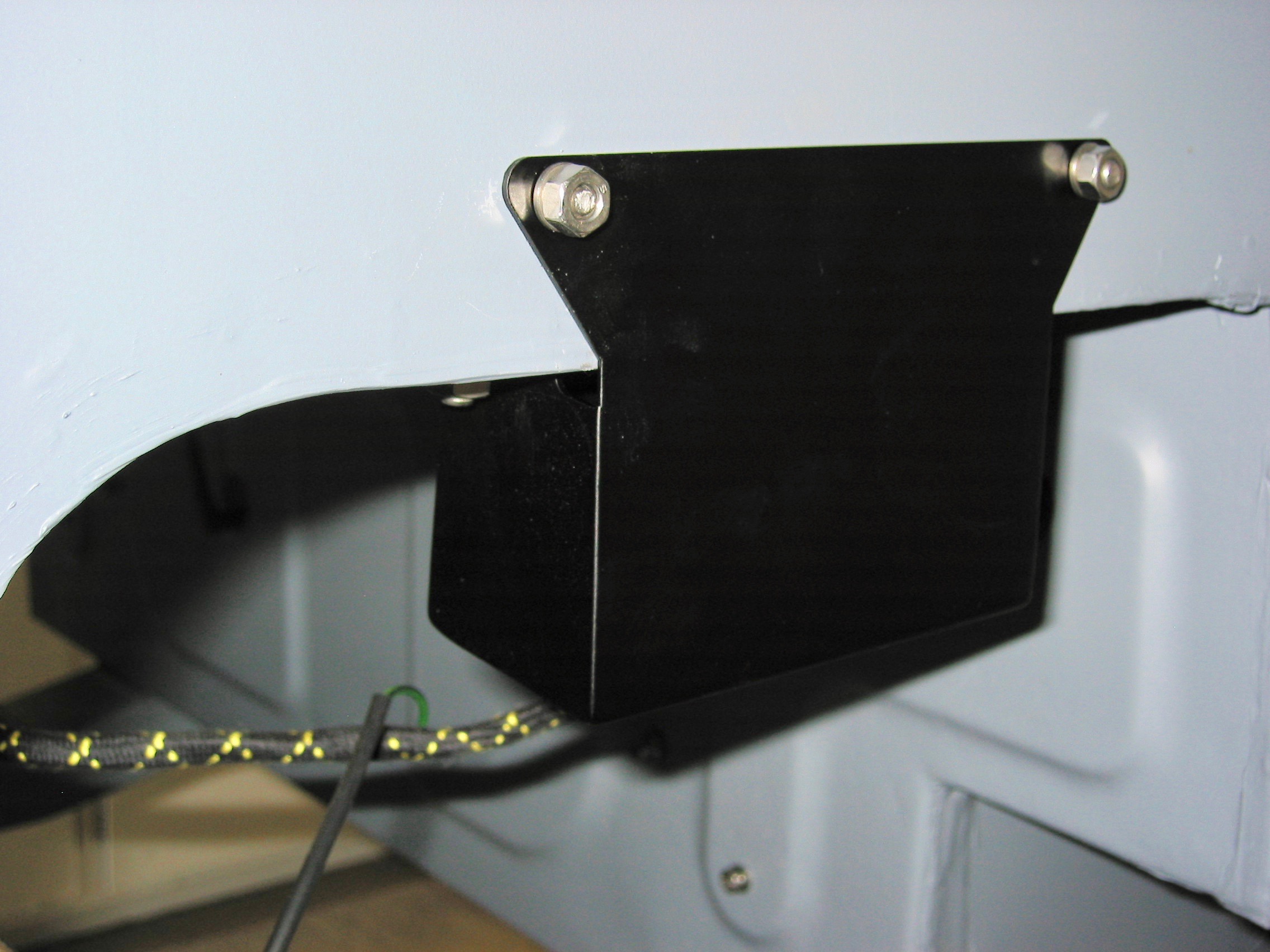
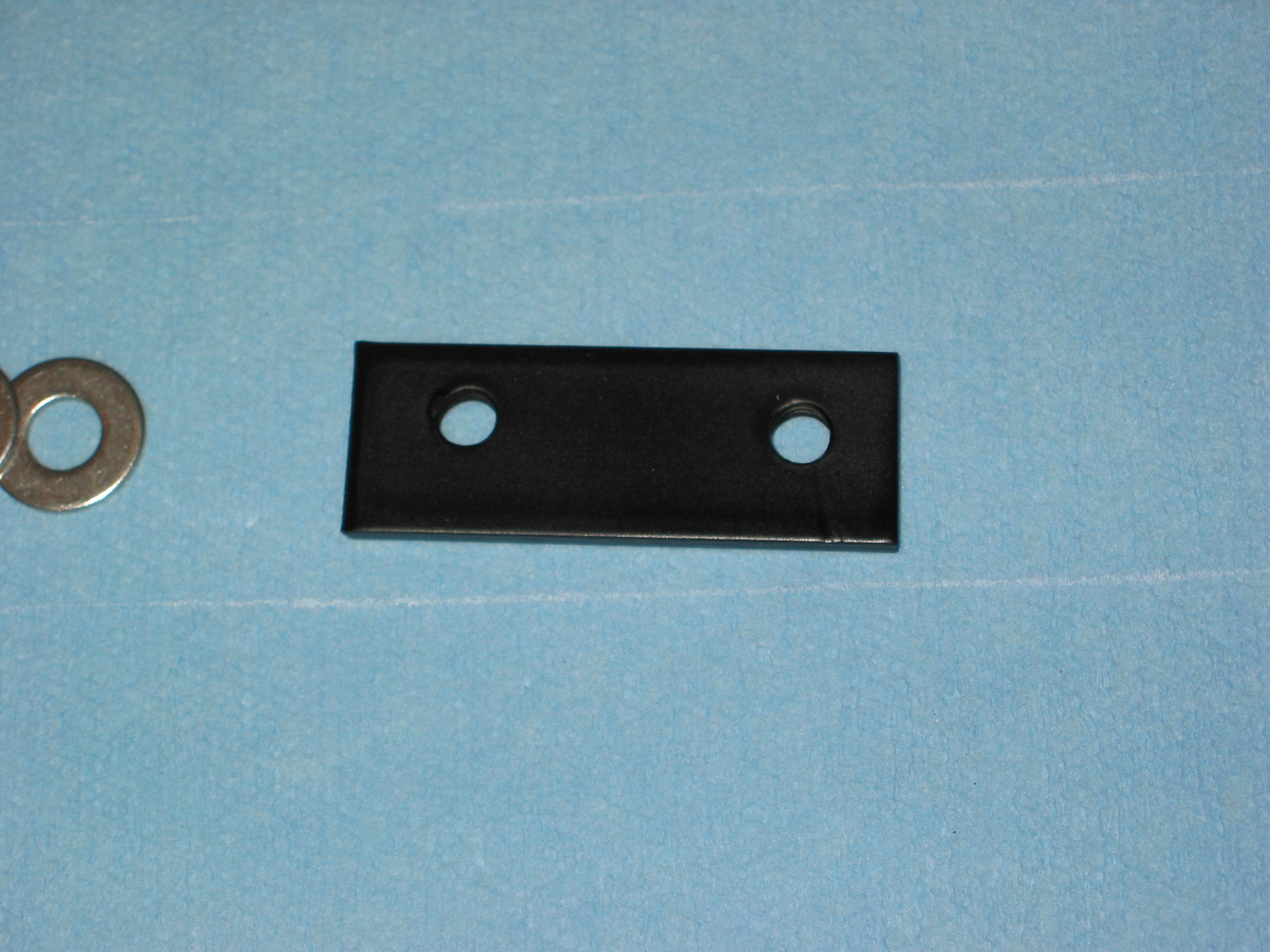
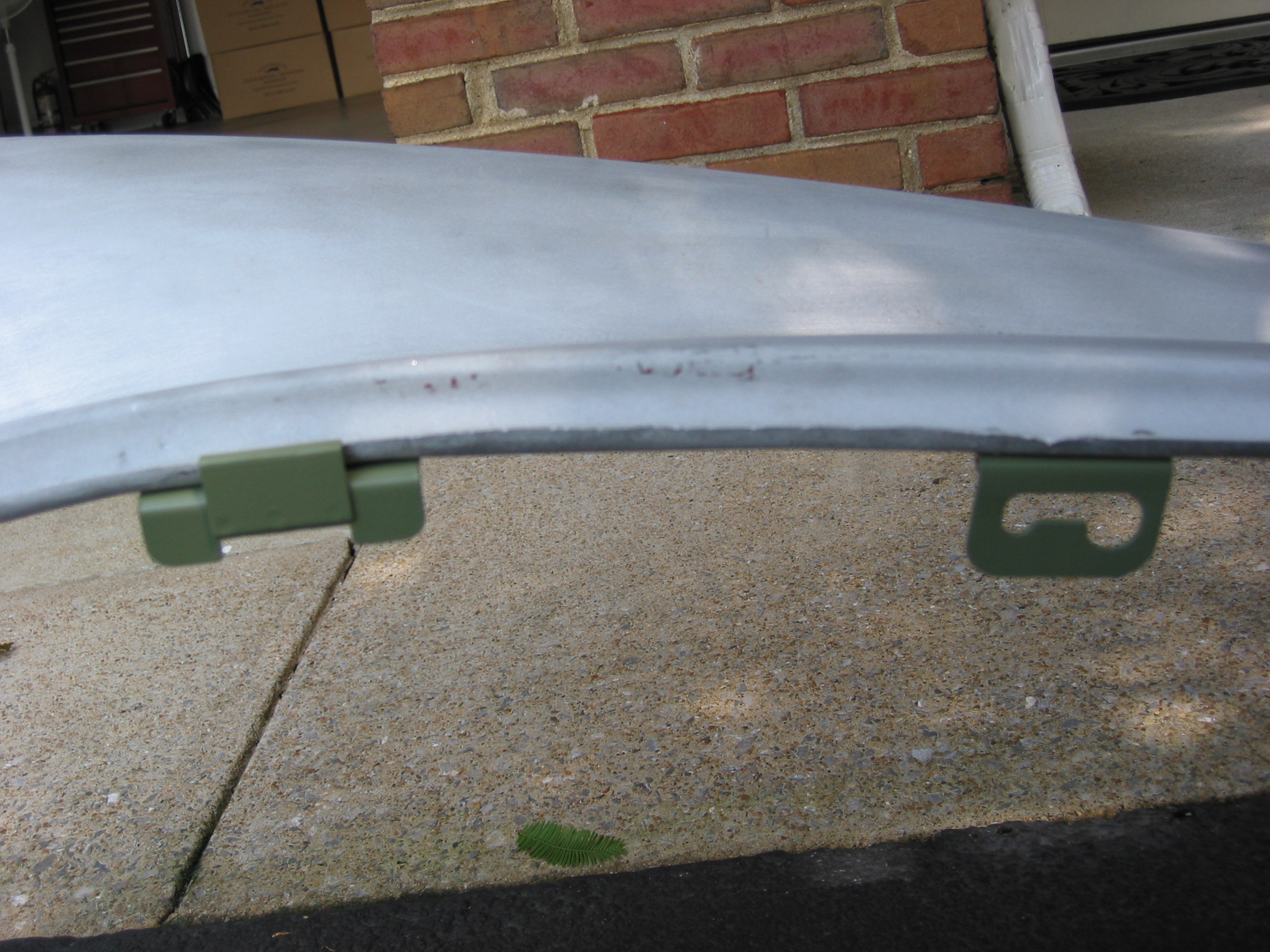
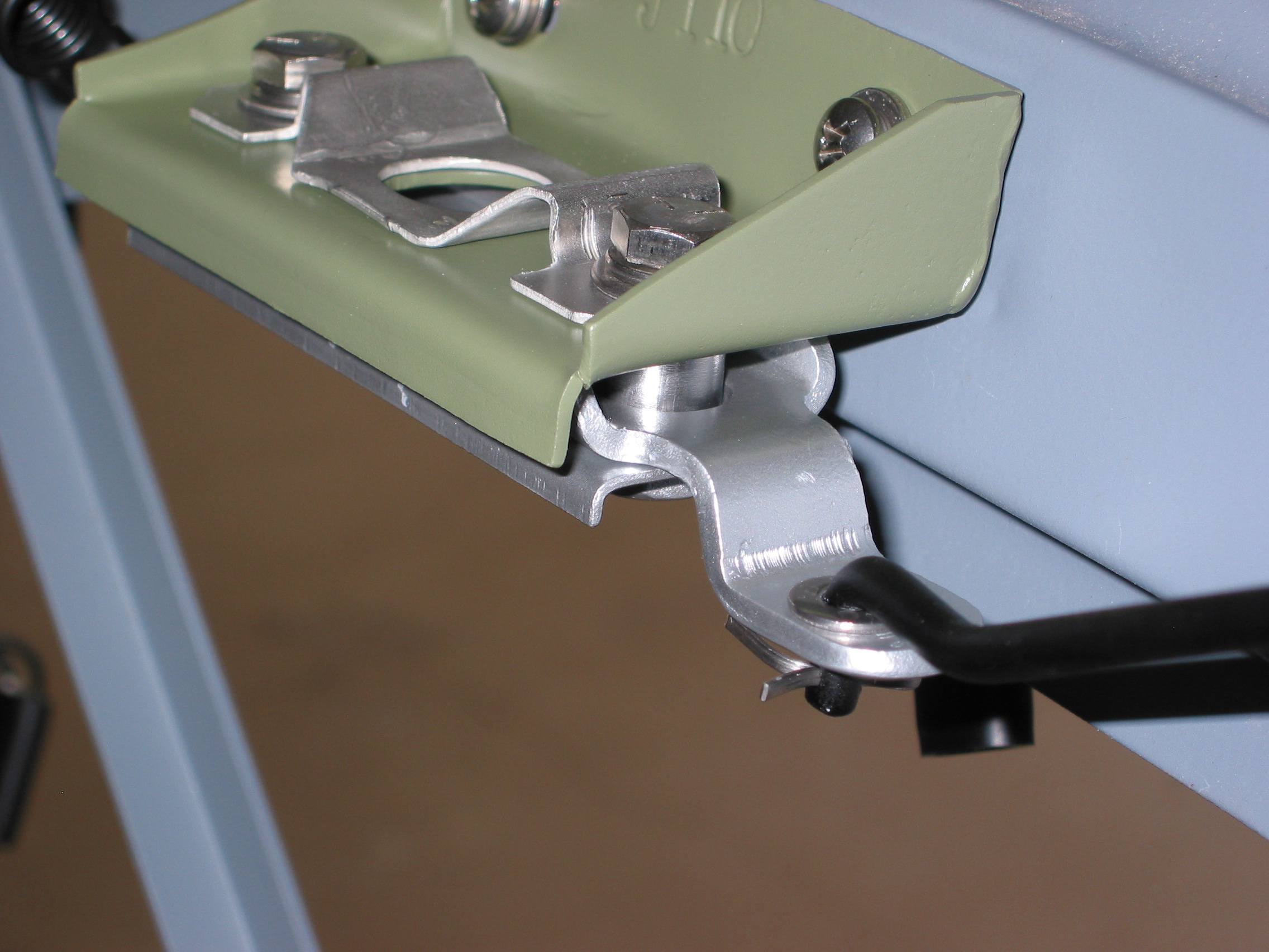
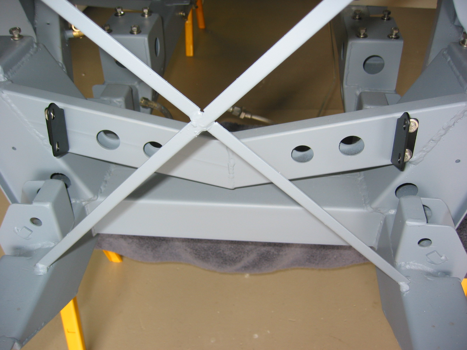
We made a little bracket to support an 8-pin Deutsch connector at the front of the valance. This connector will mate with an 8-pin bonnet connector to deliver power to the headlights, flashers, running lights and auxiliary driving lights if we decide to mount them.
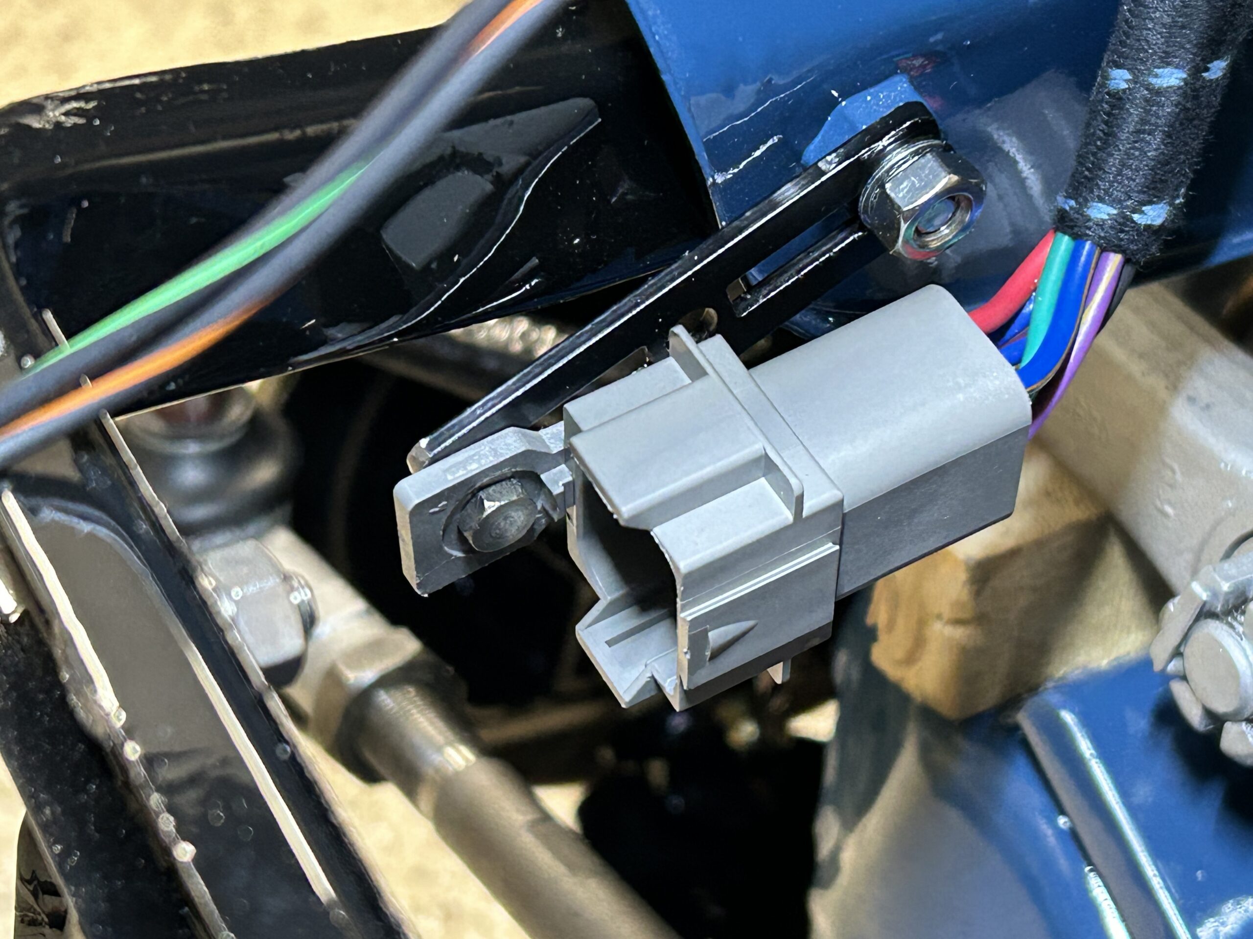
8 pin Deutsch Connector
We then installed the twin Hella horns and made the wiring connections. This did involve using a four way bullet connector to receive and supply power to both horns. A double spade connector was used to facilitate the wiring connections for the ground wires.
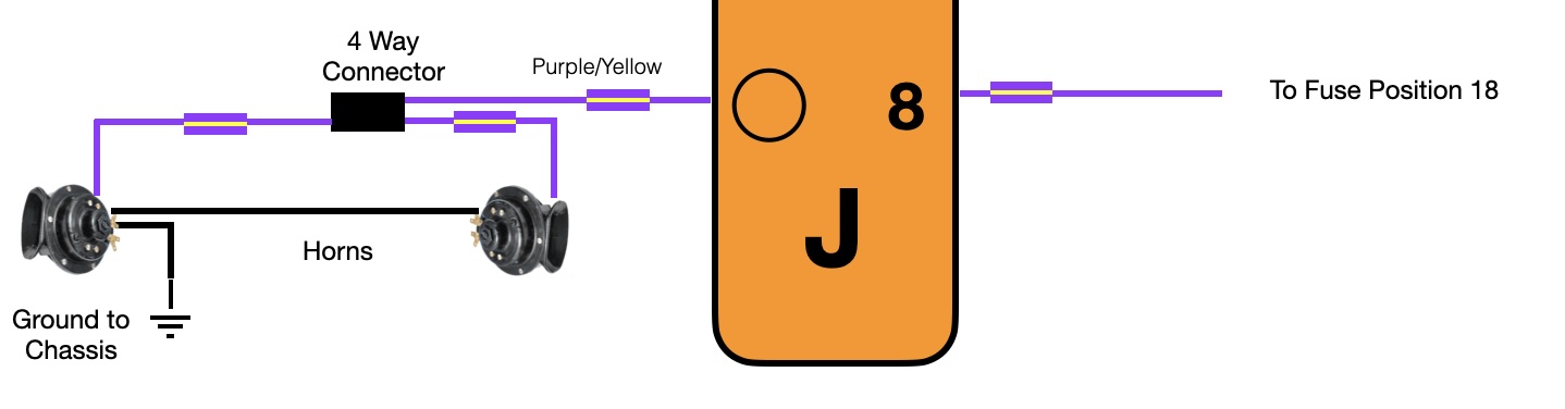
Horns Wiring
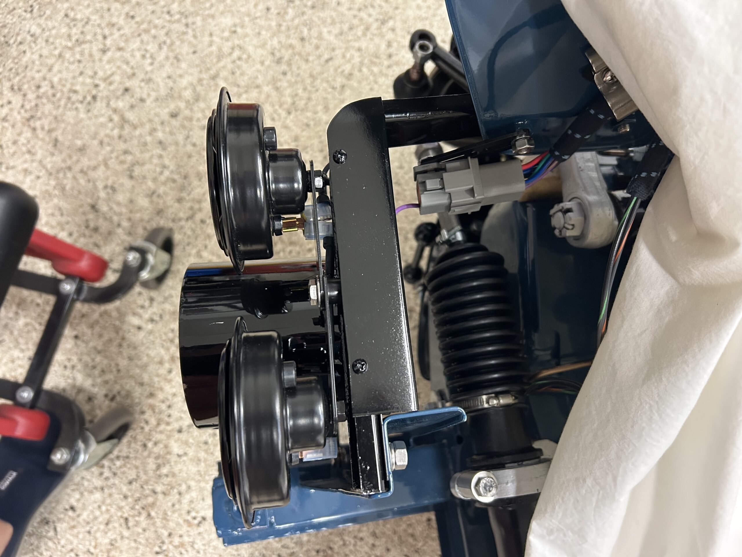
Hella horns installed with wiring and custom cover
The next wiring connections to be made were for the wiper motor. Duestch connector “H” is used to connect the wires from the wiper motor to the Wiper Controller mounted behind the dash. The three wires, encased in shrink tubing, come through the firewall. The green wire connects to wiper motor terminal #2 and the green/black wire connects to terminal #1. A black ground wire connects to terminal #3.
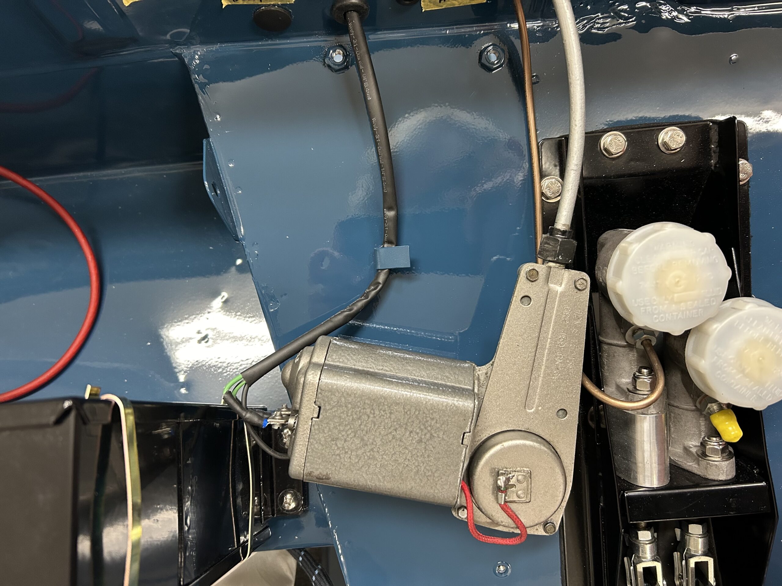
Wiper Motor Wiring Connections
The next item to wire was the ignition coil. The yellow/green wire from the harness connects to the (-) terminal of the coil. The white wire from the harness connects to the (+) terminal of the coil.
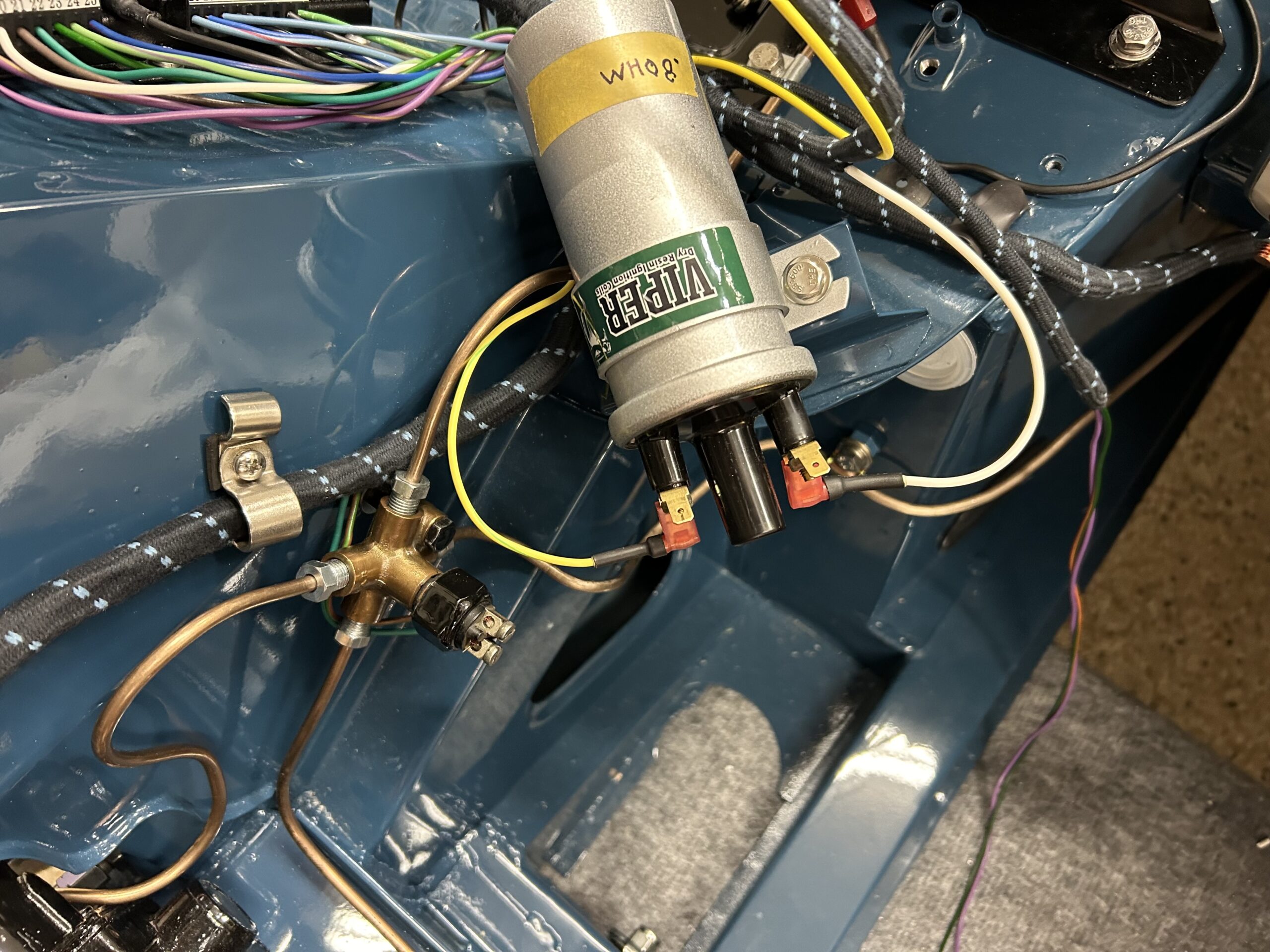
Ignition Coil Wiring
The heater blower has two black wires from the fan motor. One of those wires is connected to a yellow wire from the harness with a spade connector. The other black wire is ground and is screwed to the chassis.
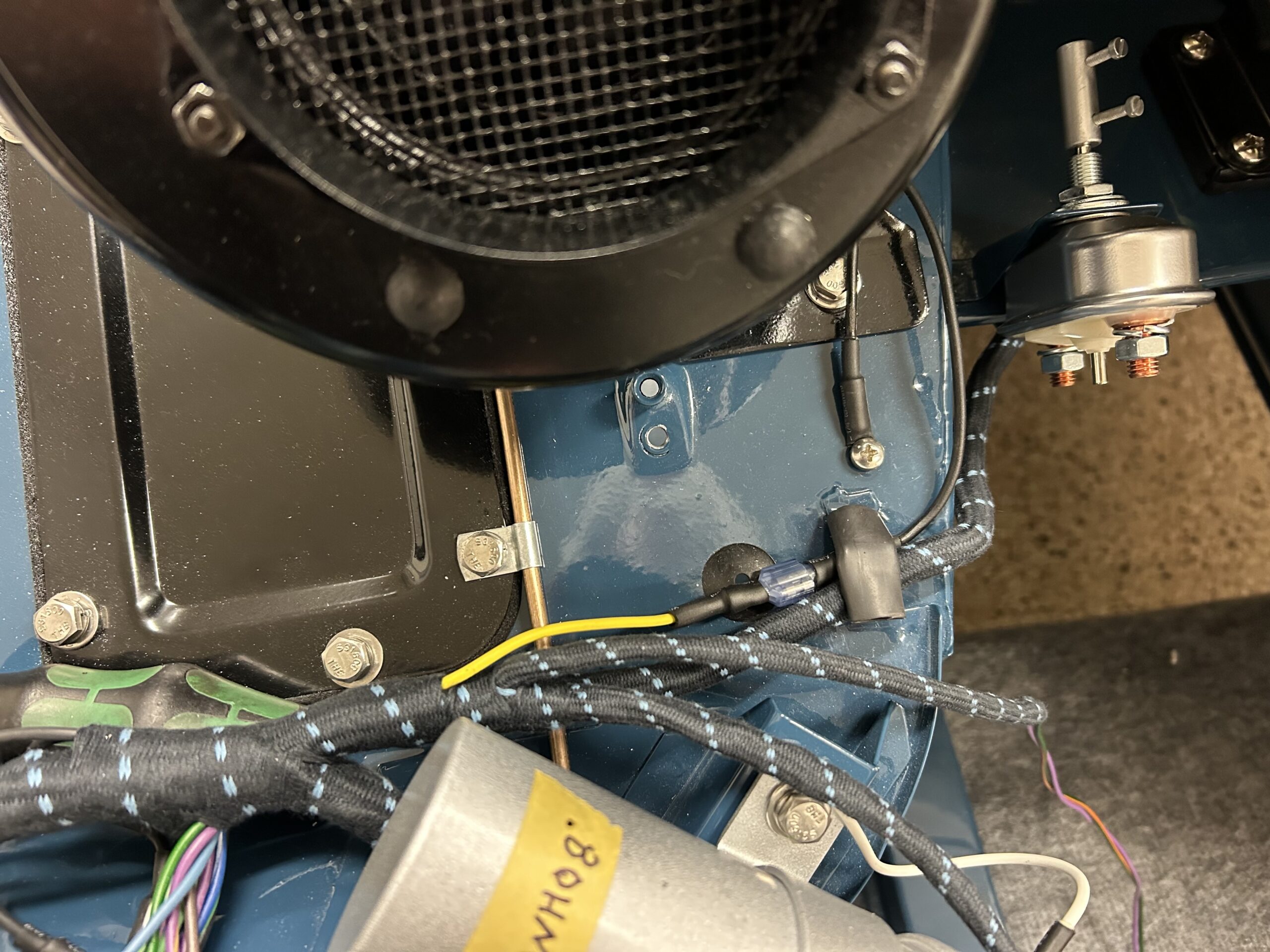
Heater blower wiring
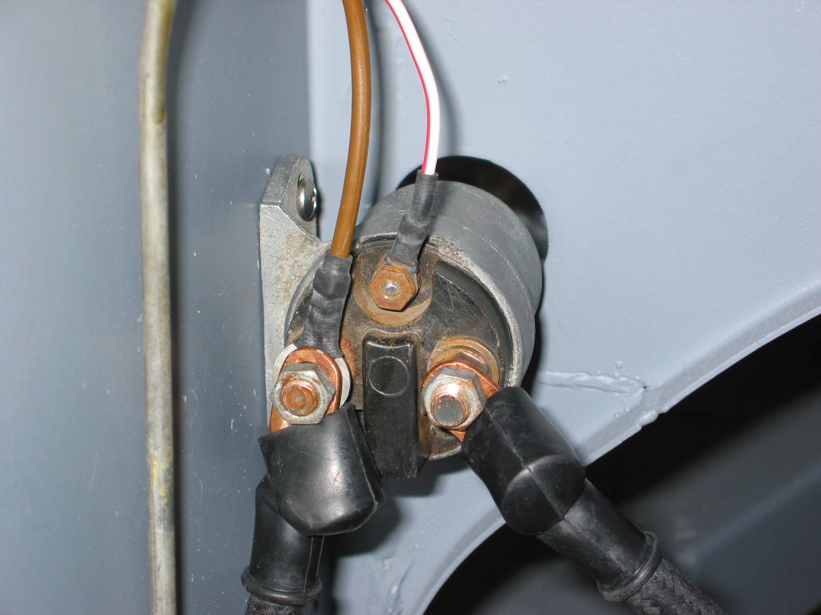
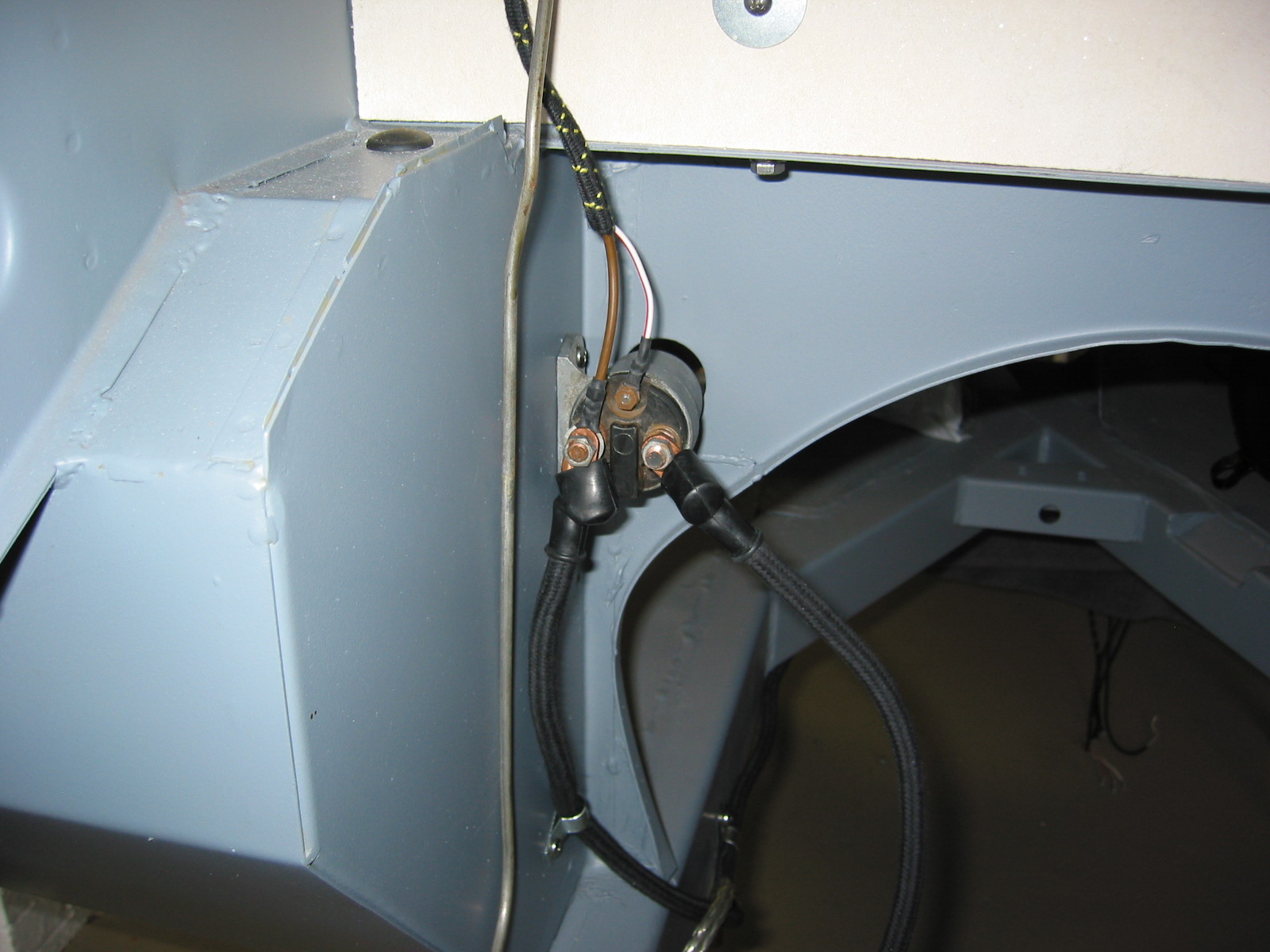
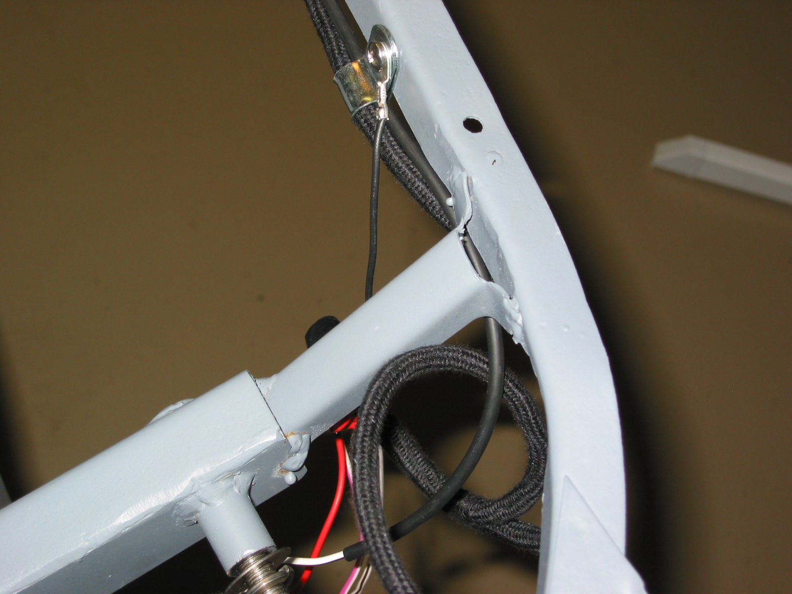
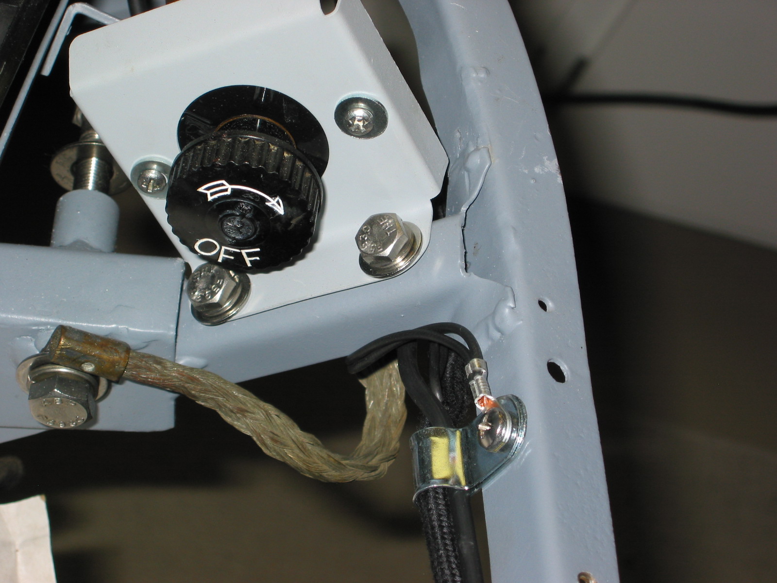
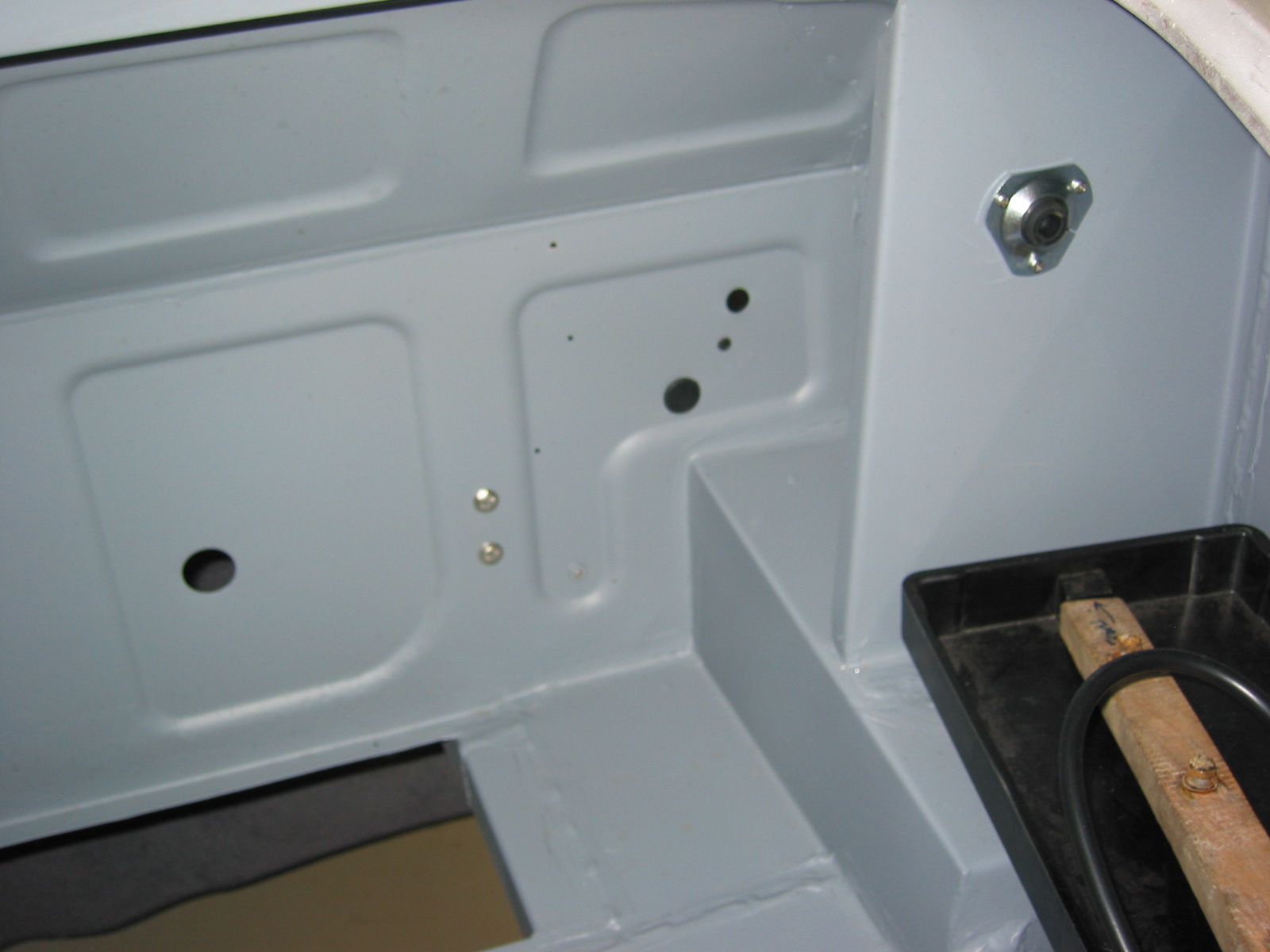
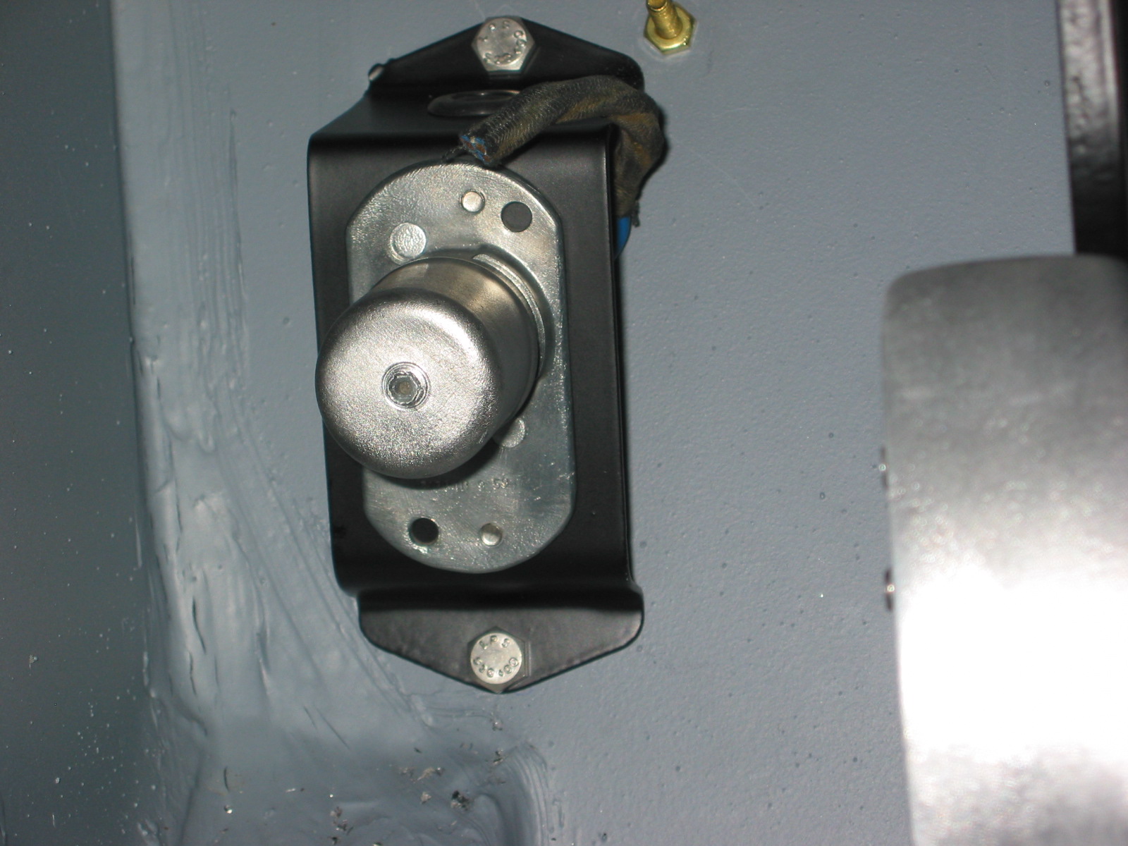
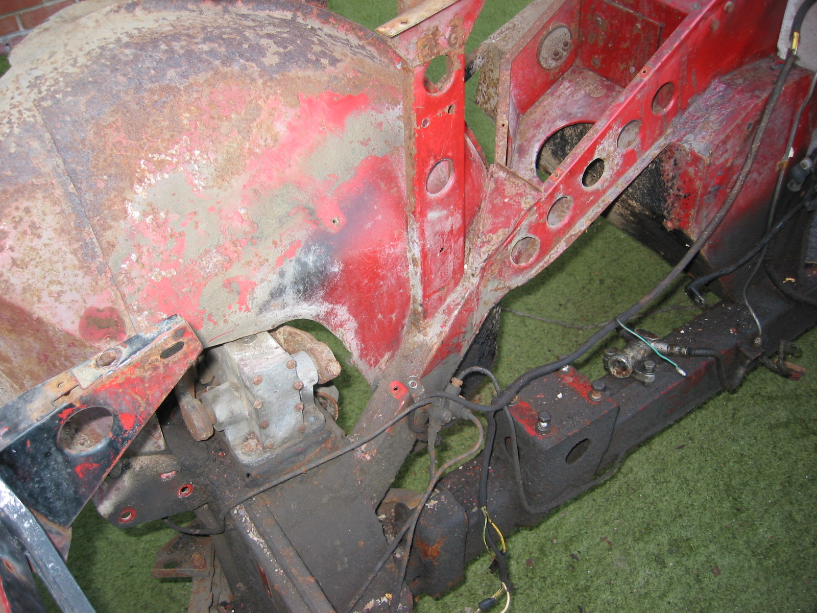
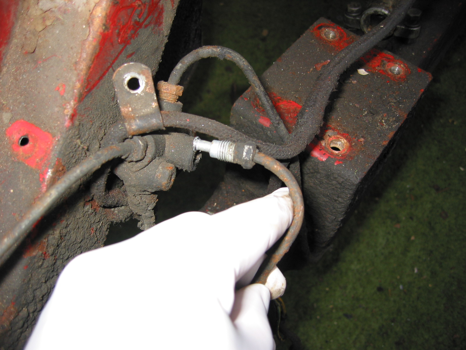
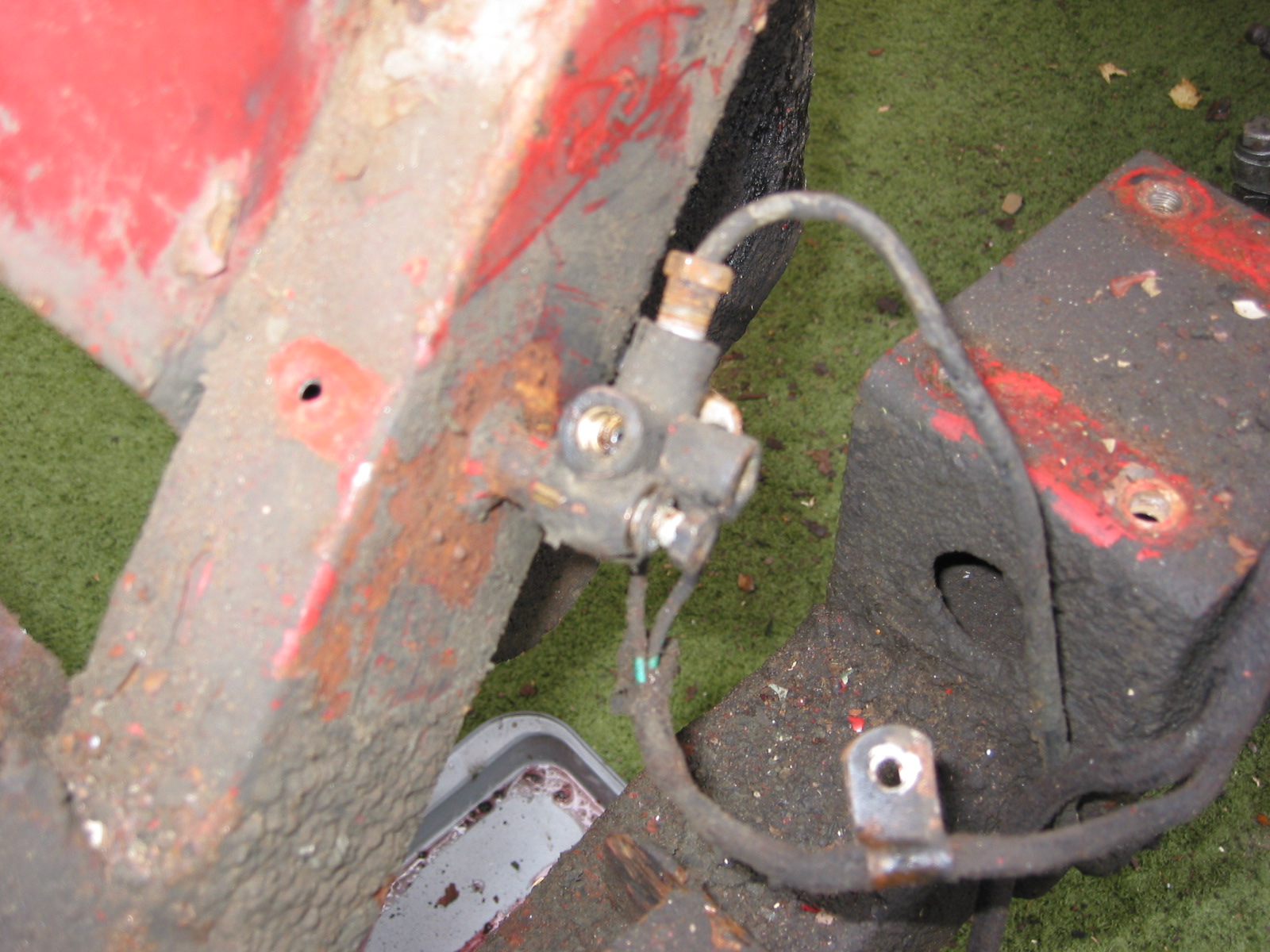
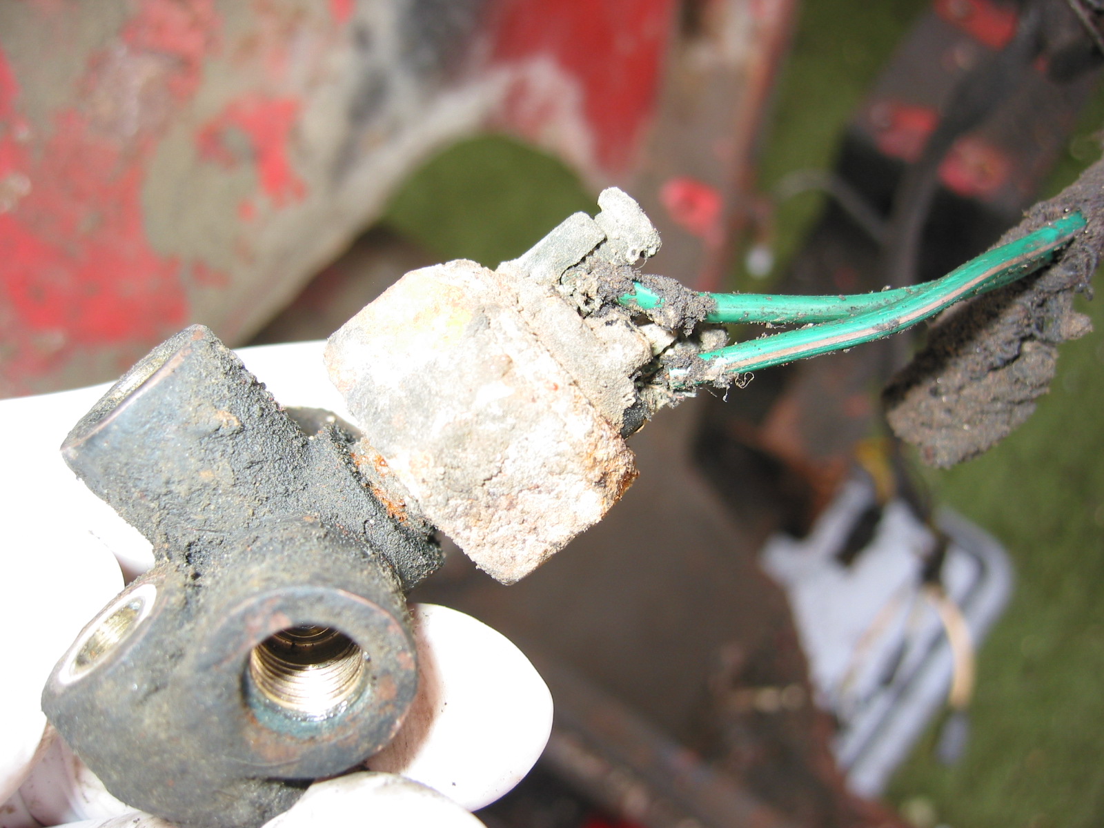
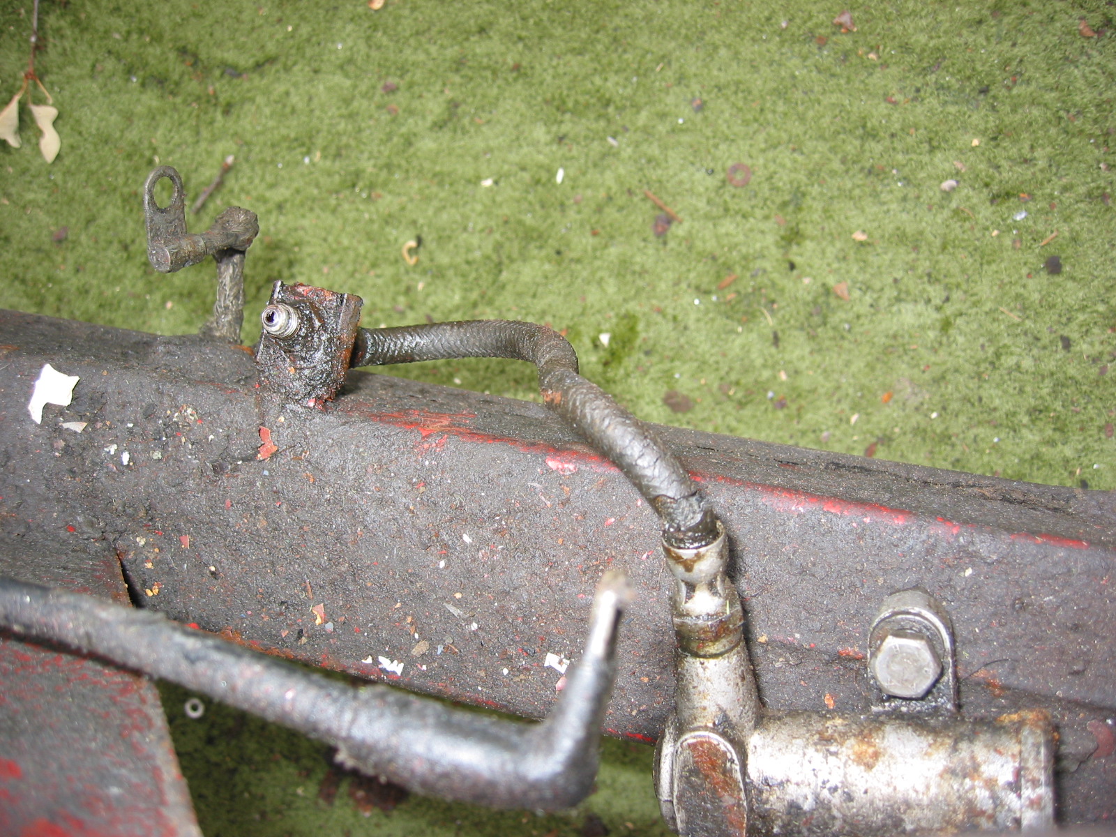
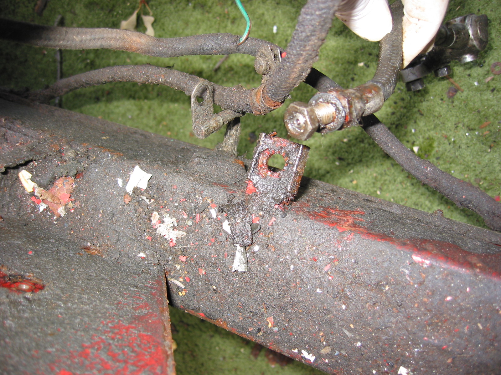
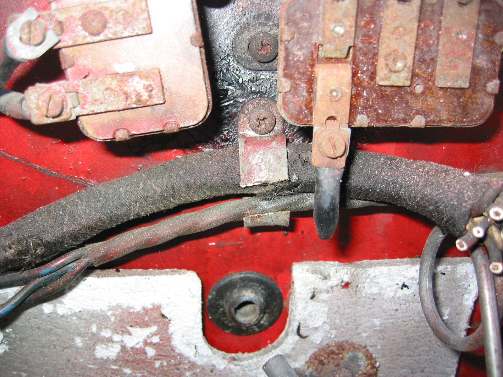
The hydraulic brake switch is mounted on the RH engine bay valance. A teal green wire and a brown/green wire from the harness connect to the two screw terminals on the switch.
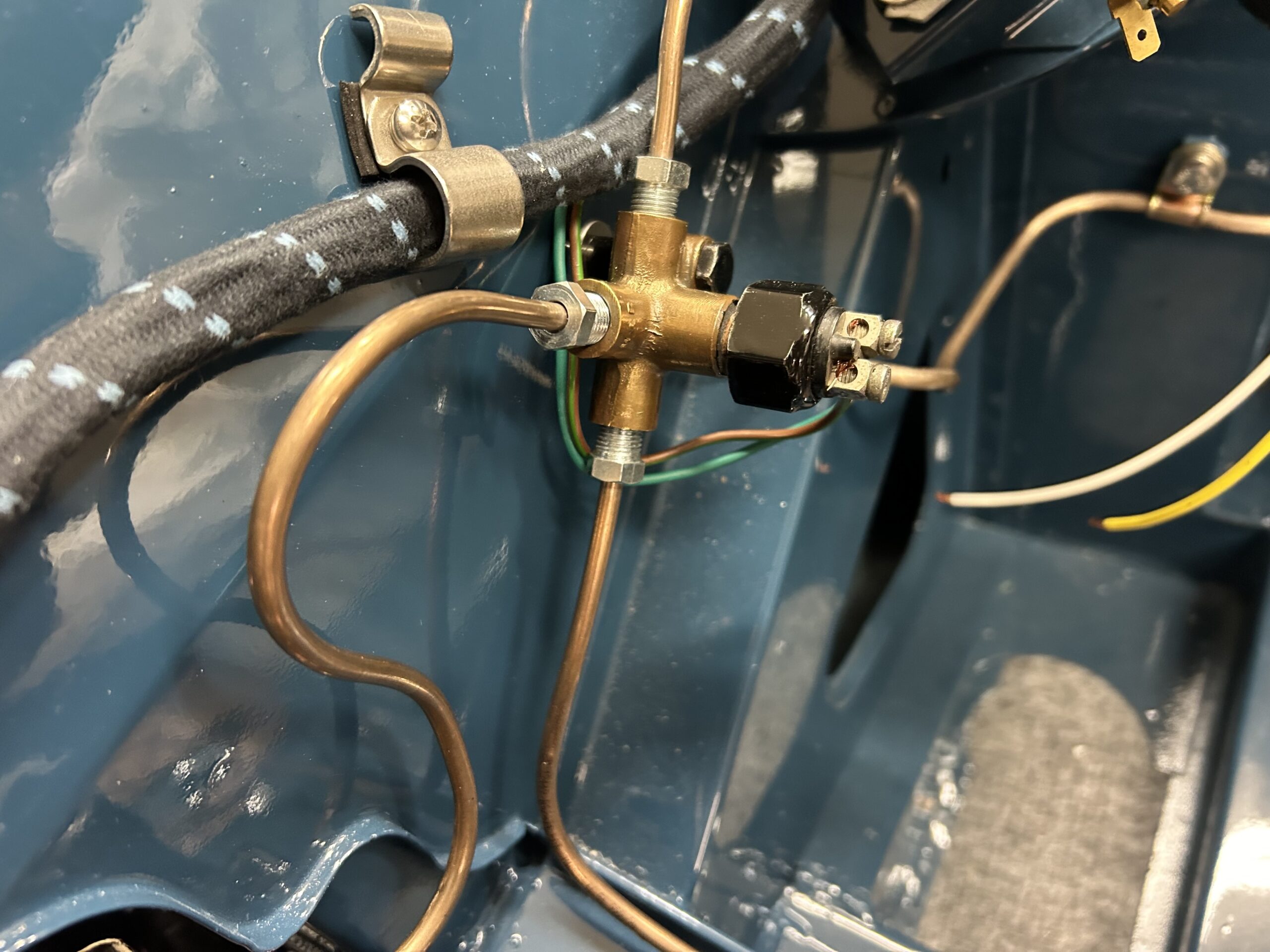
Hydraulic brake switch wiring
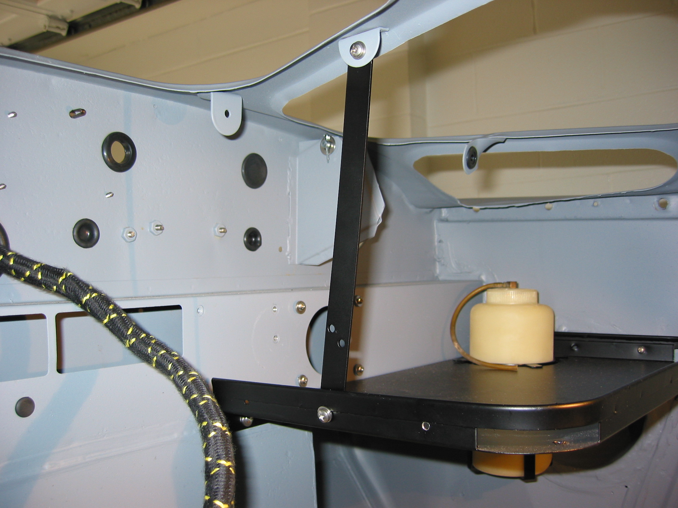
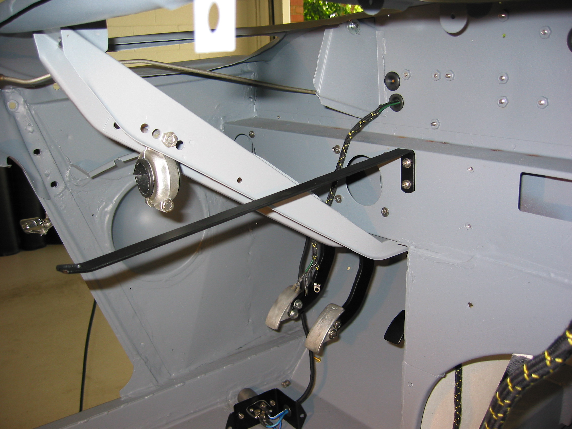
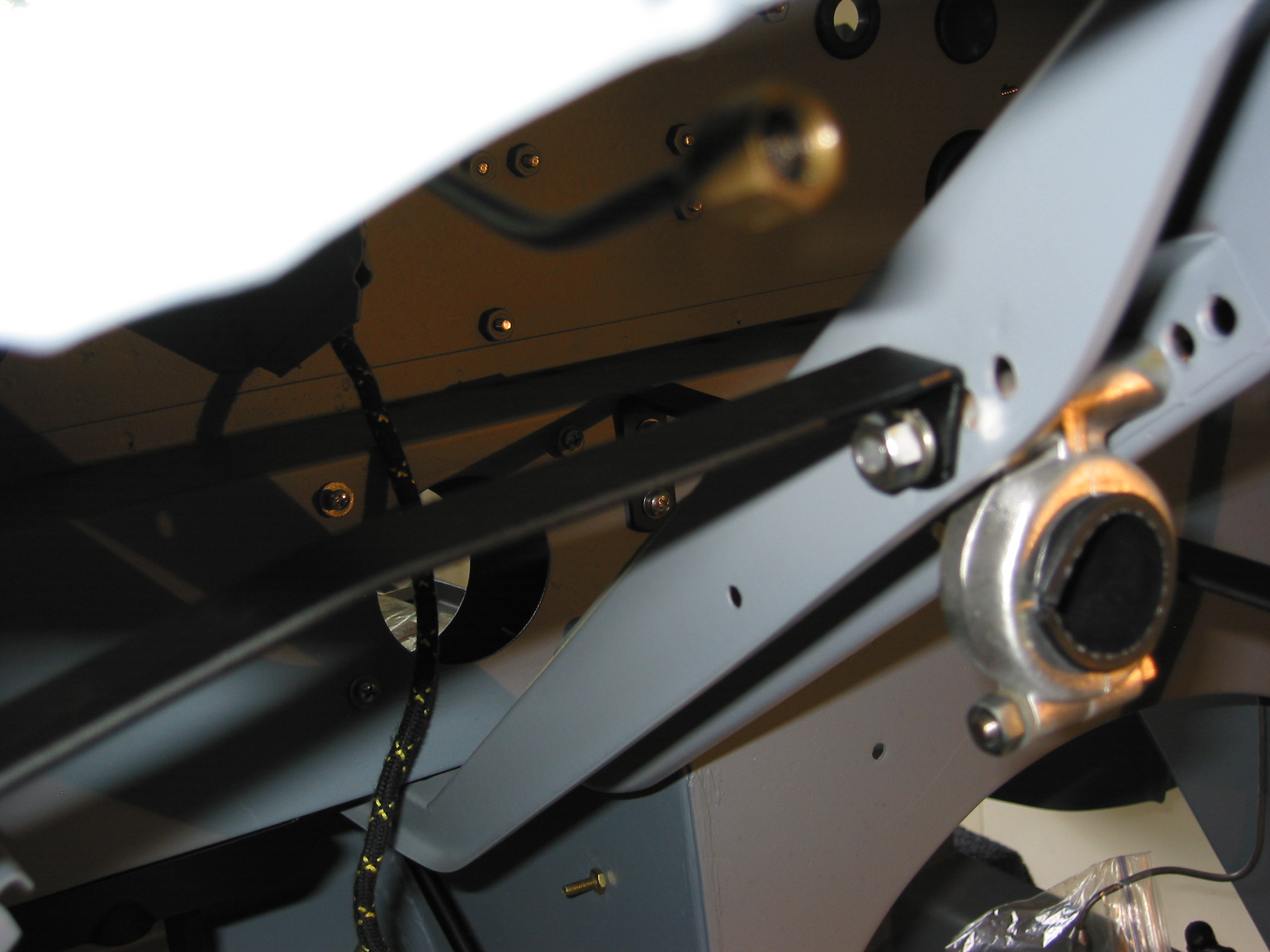
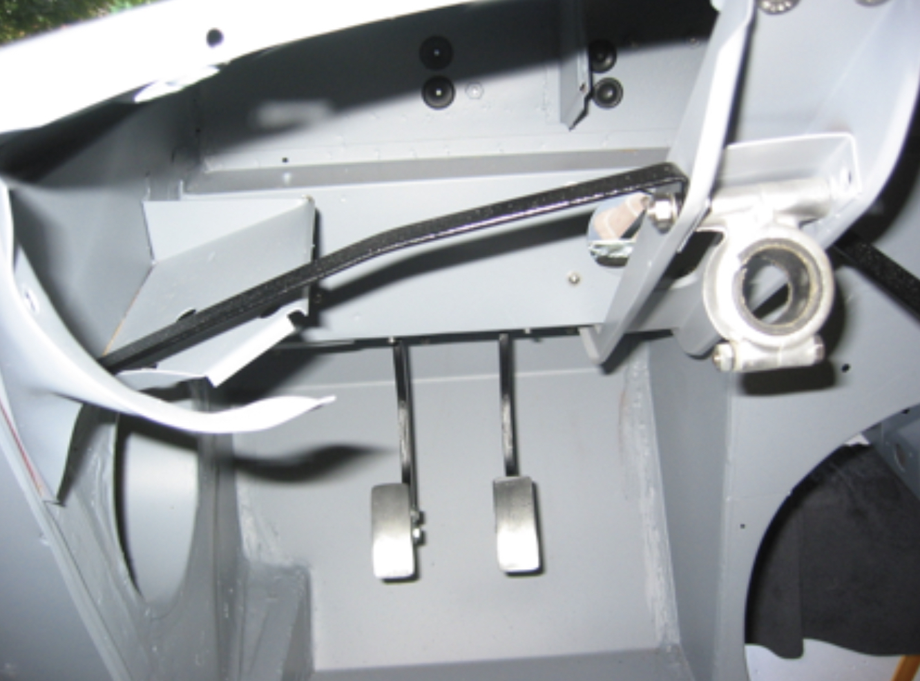
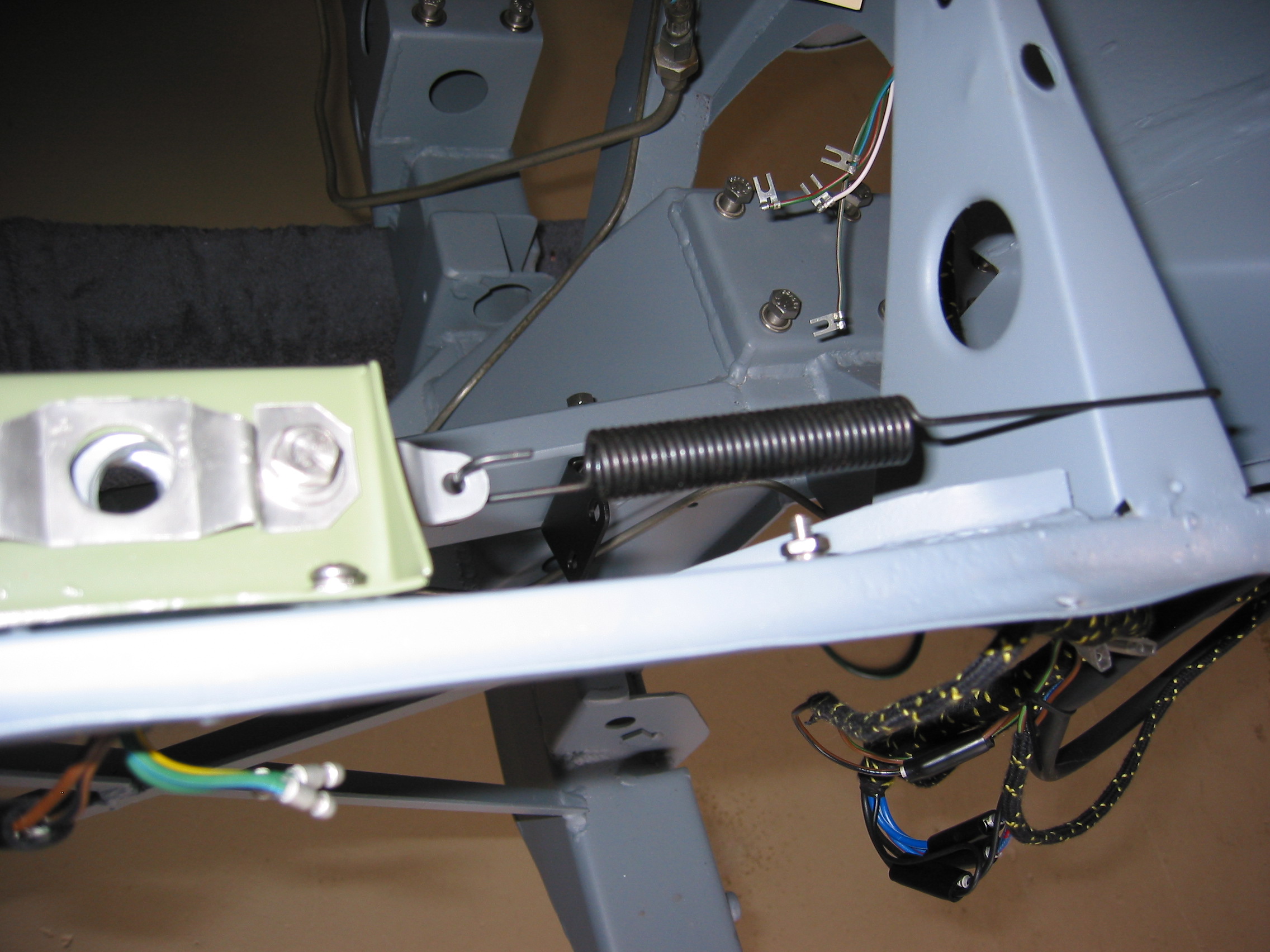
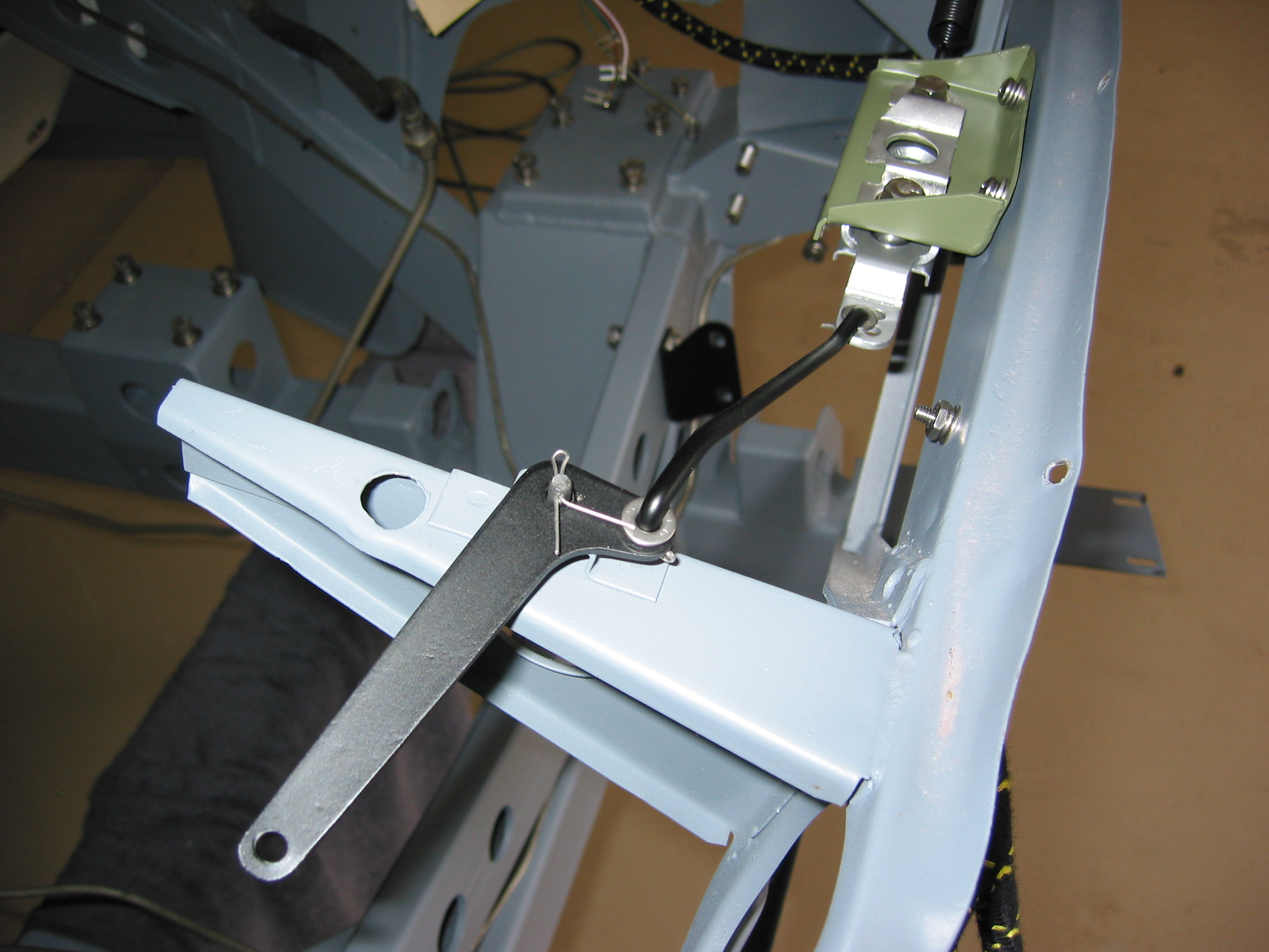
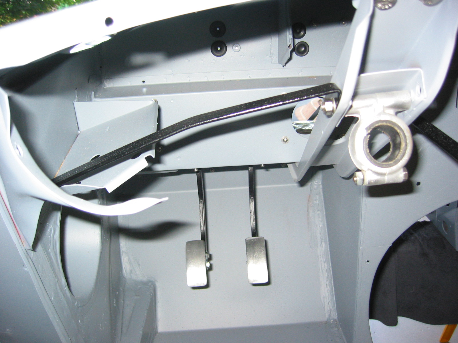
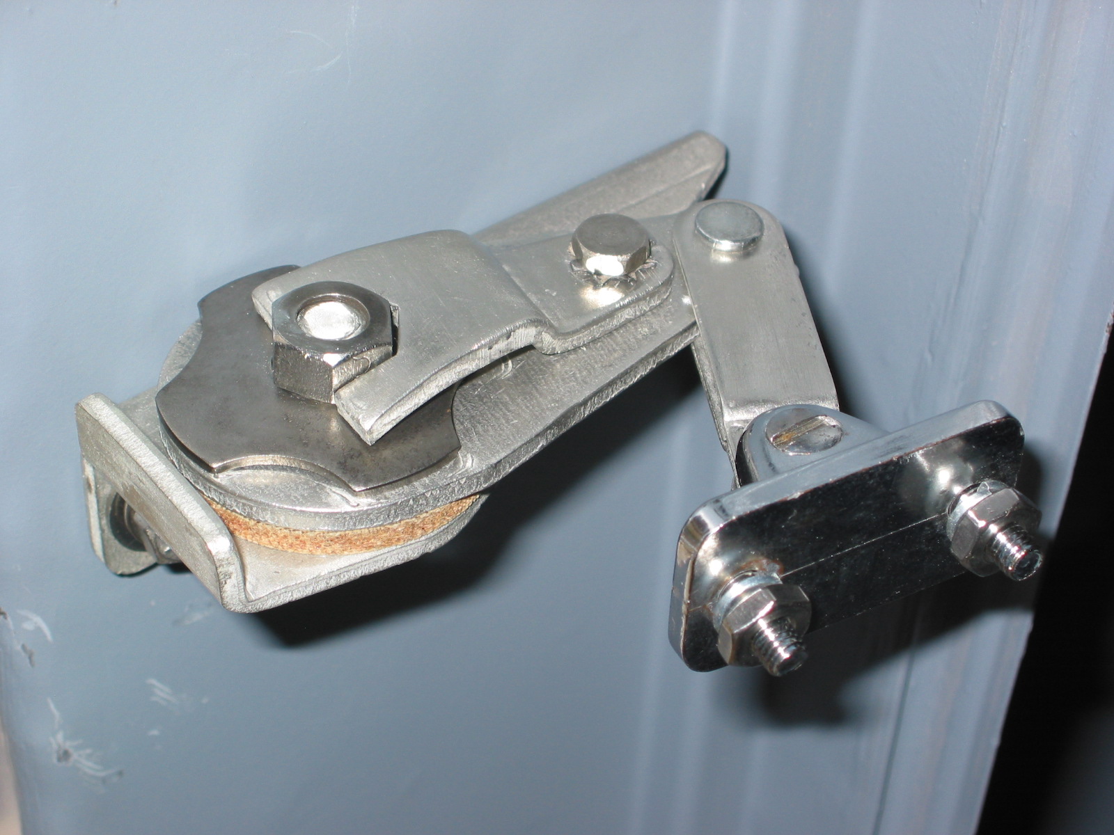
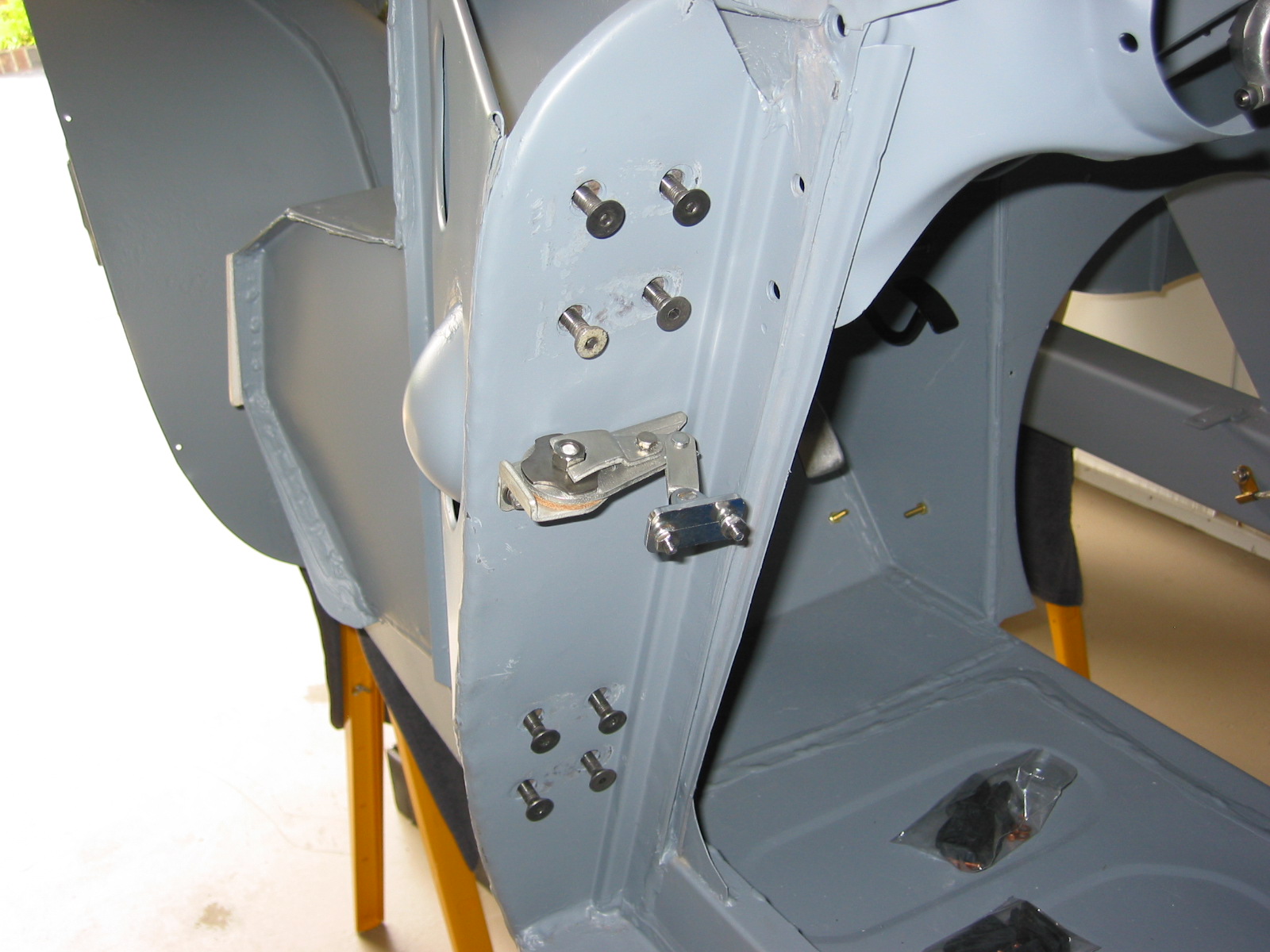
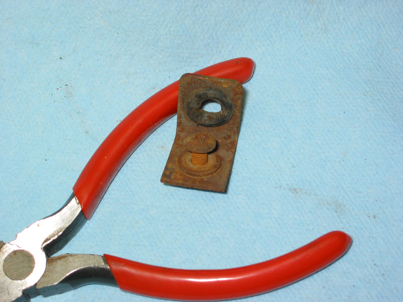
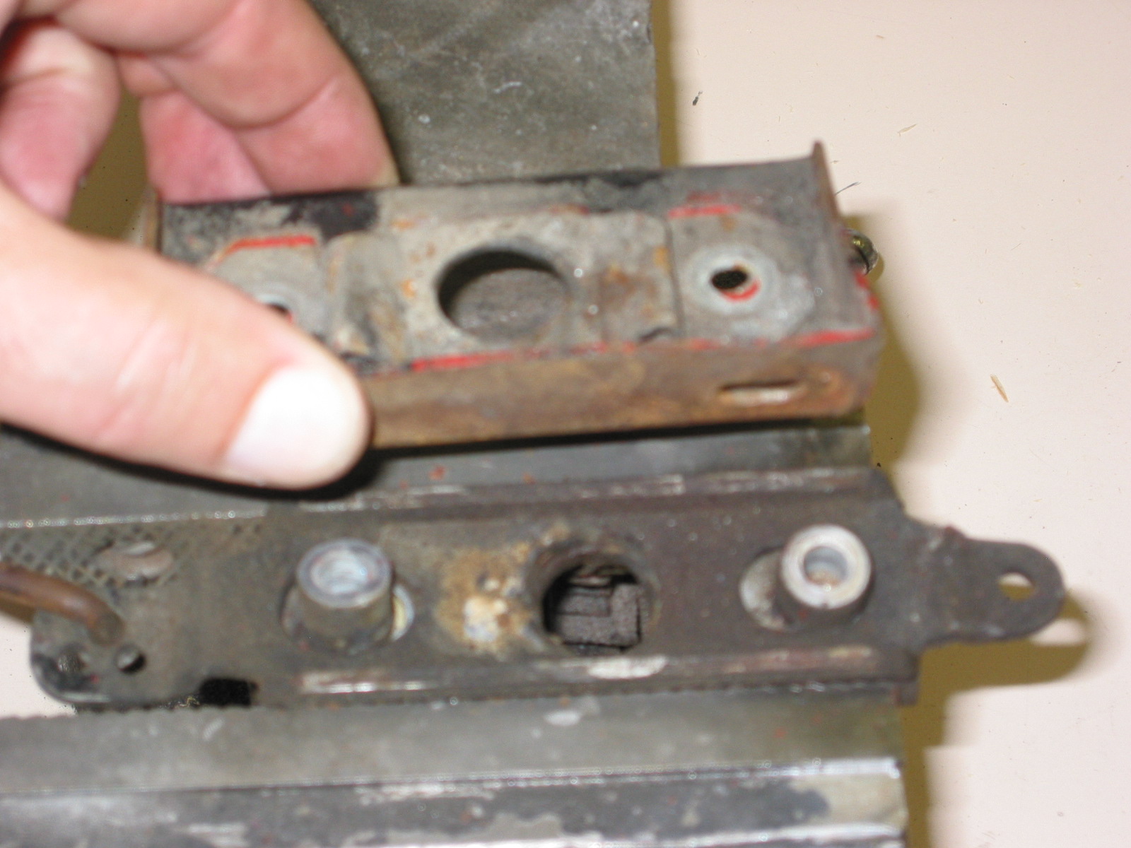
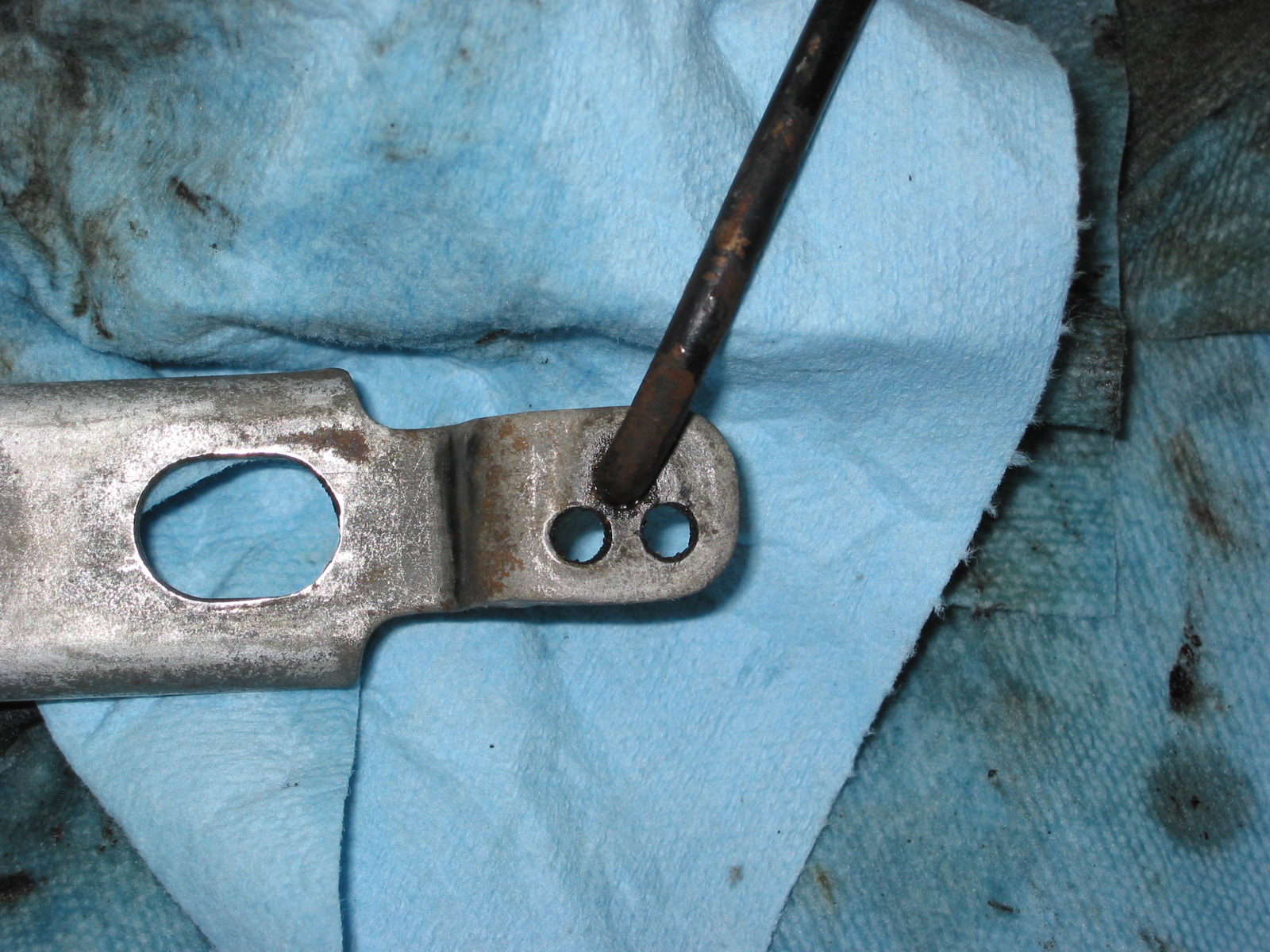
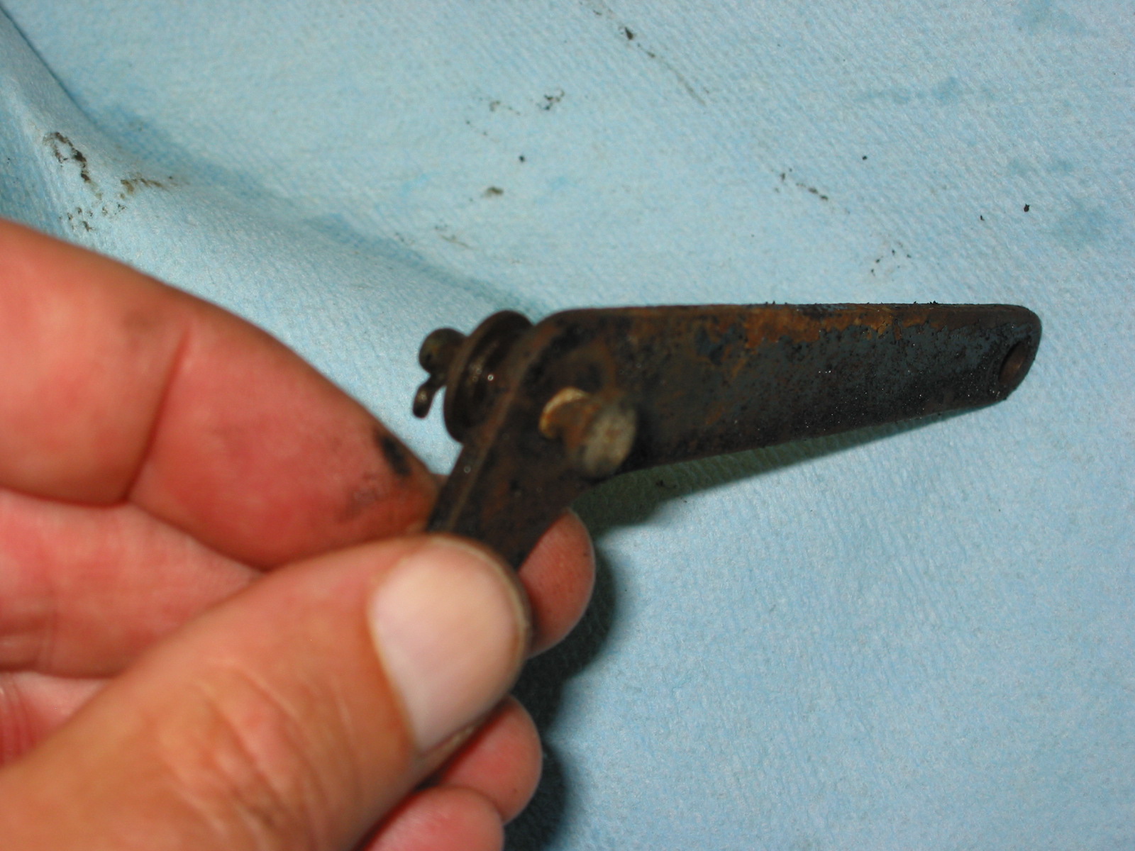
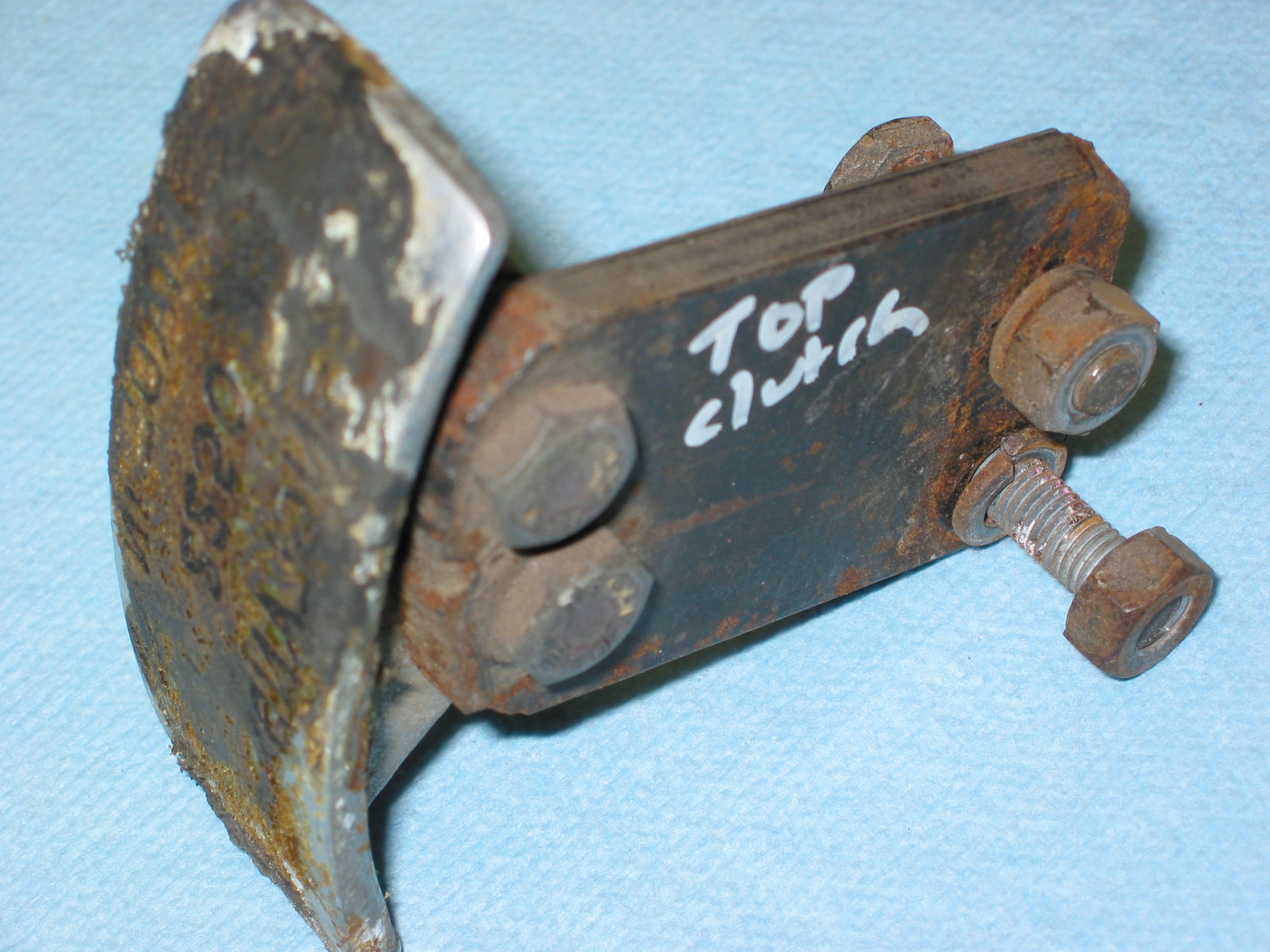
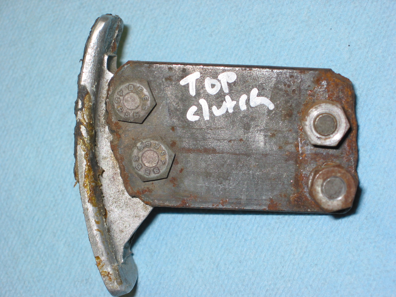
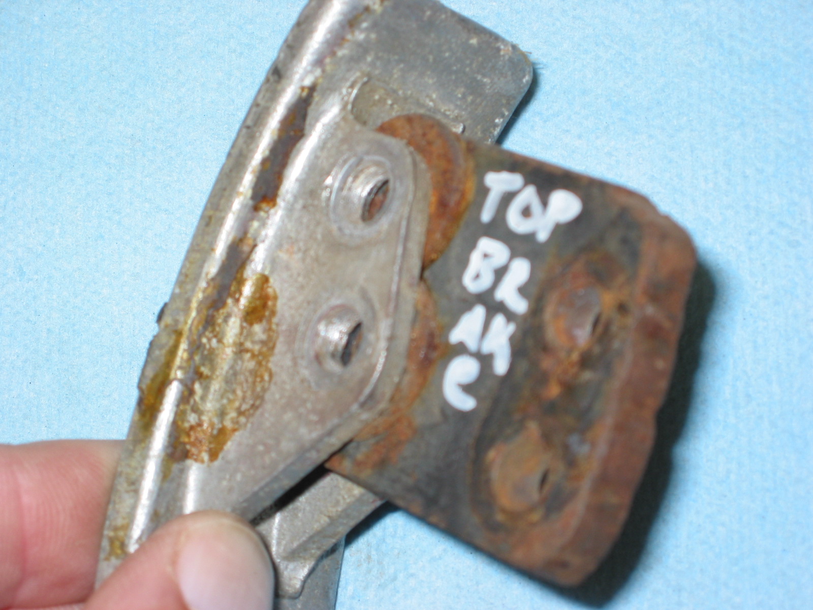
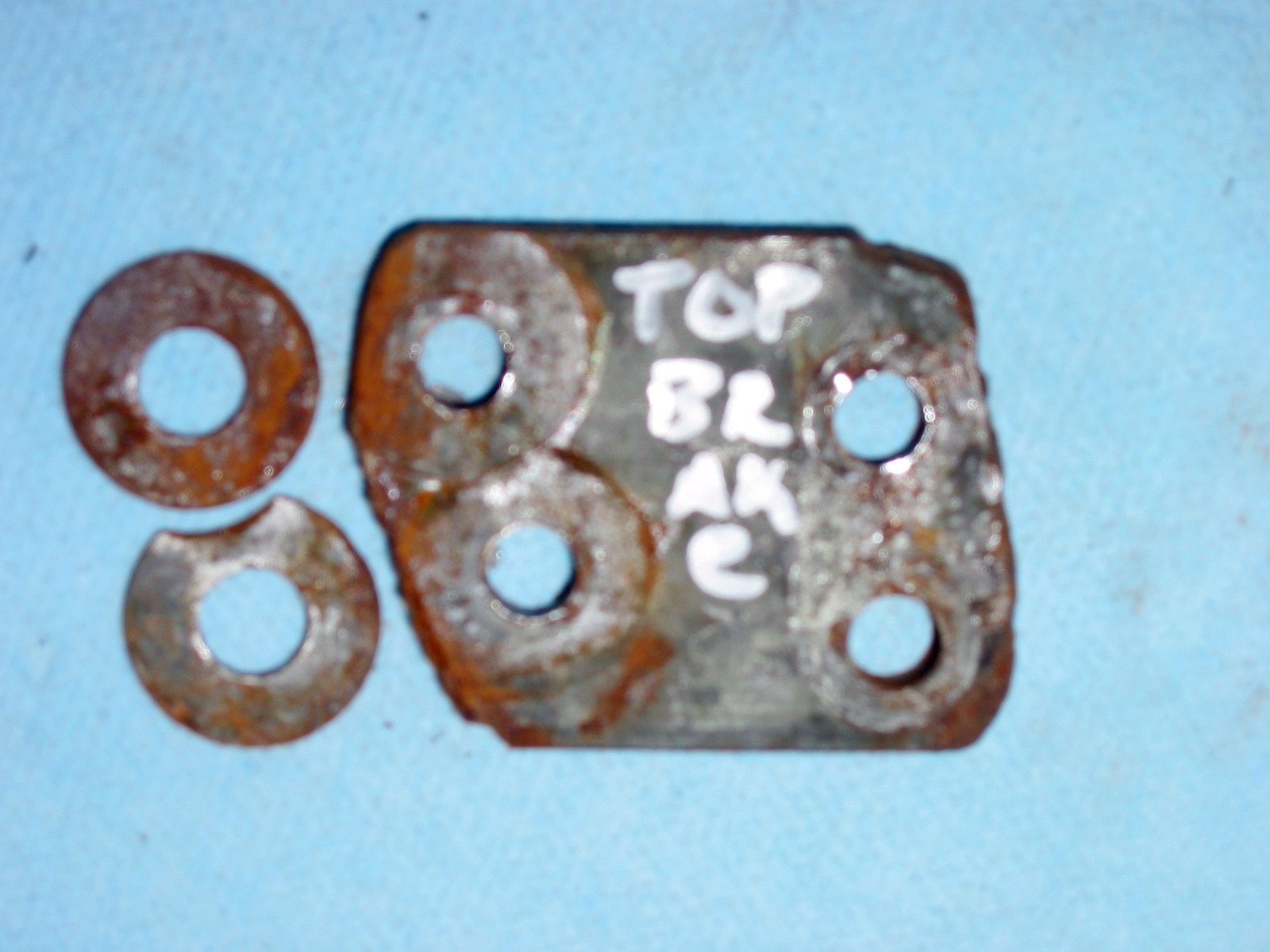
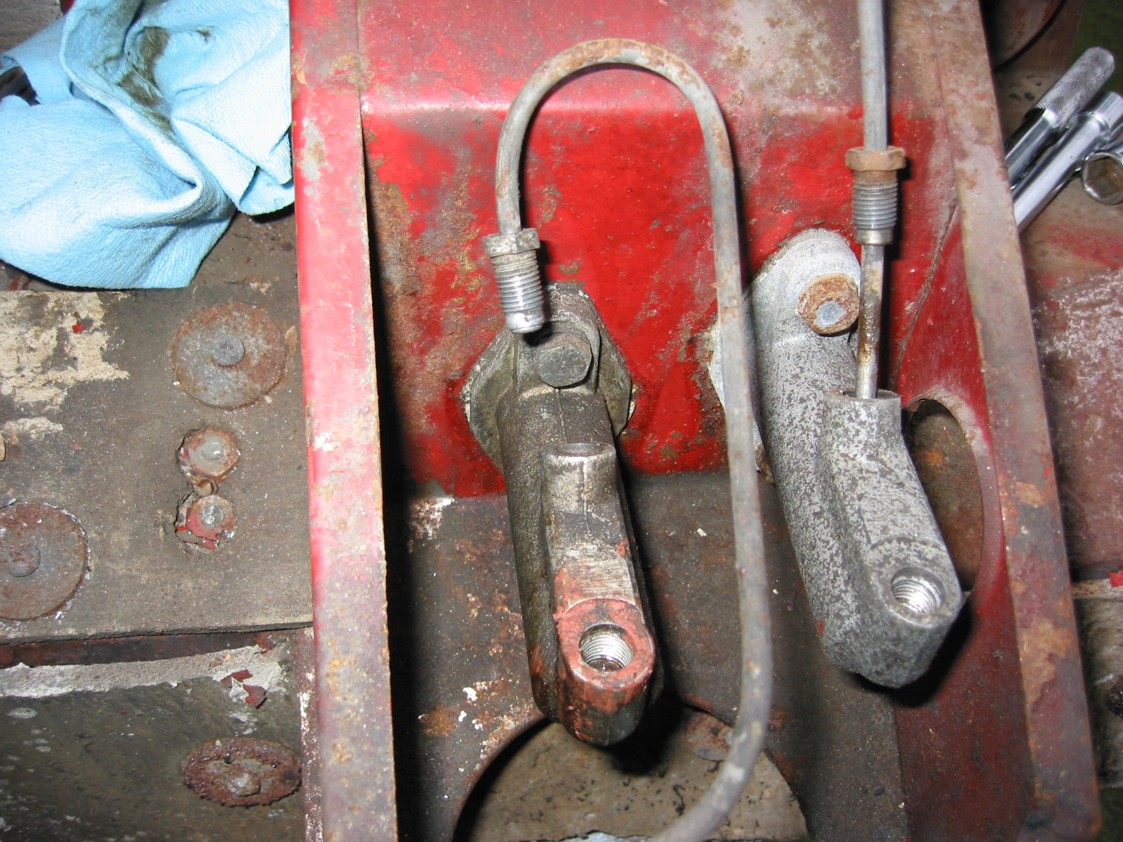
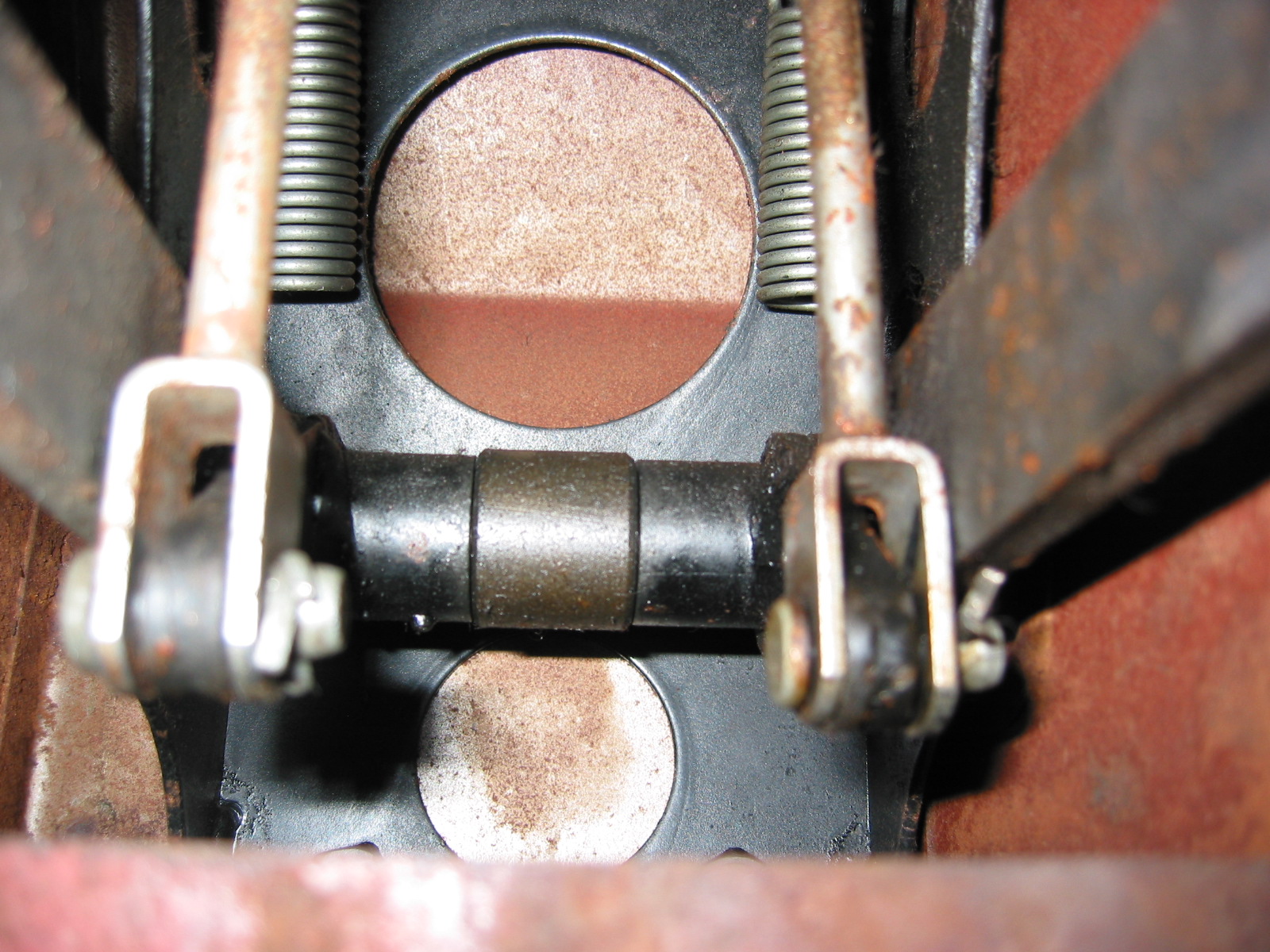
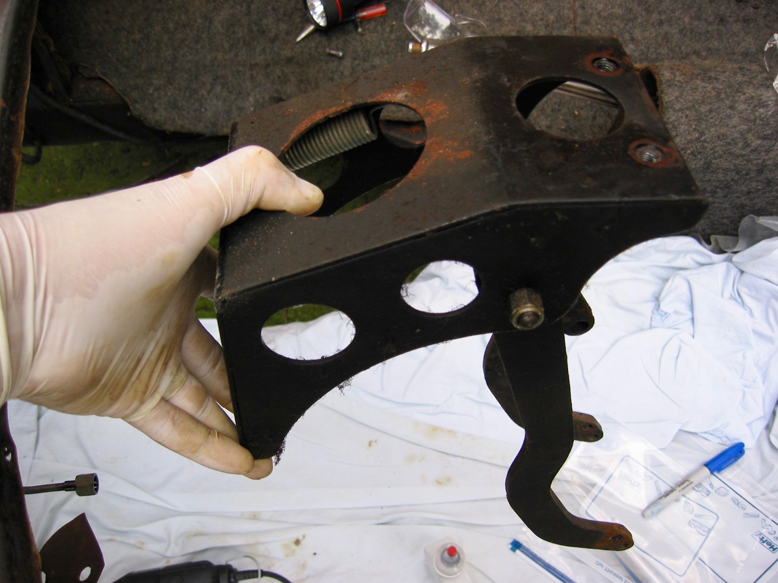
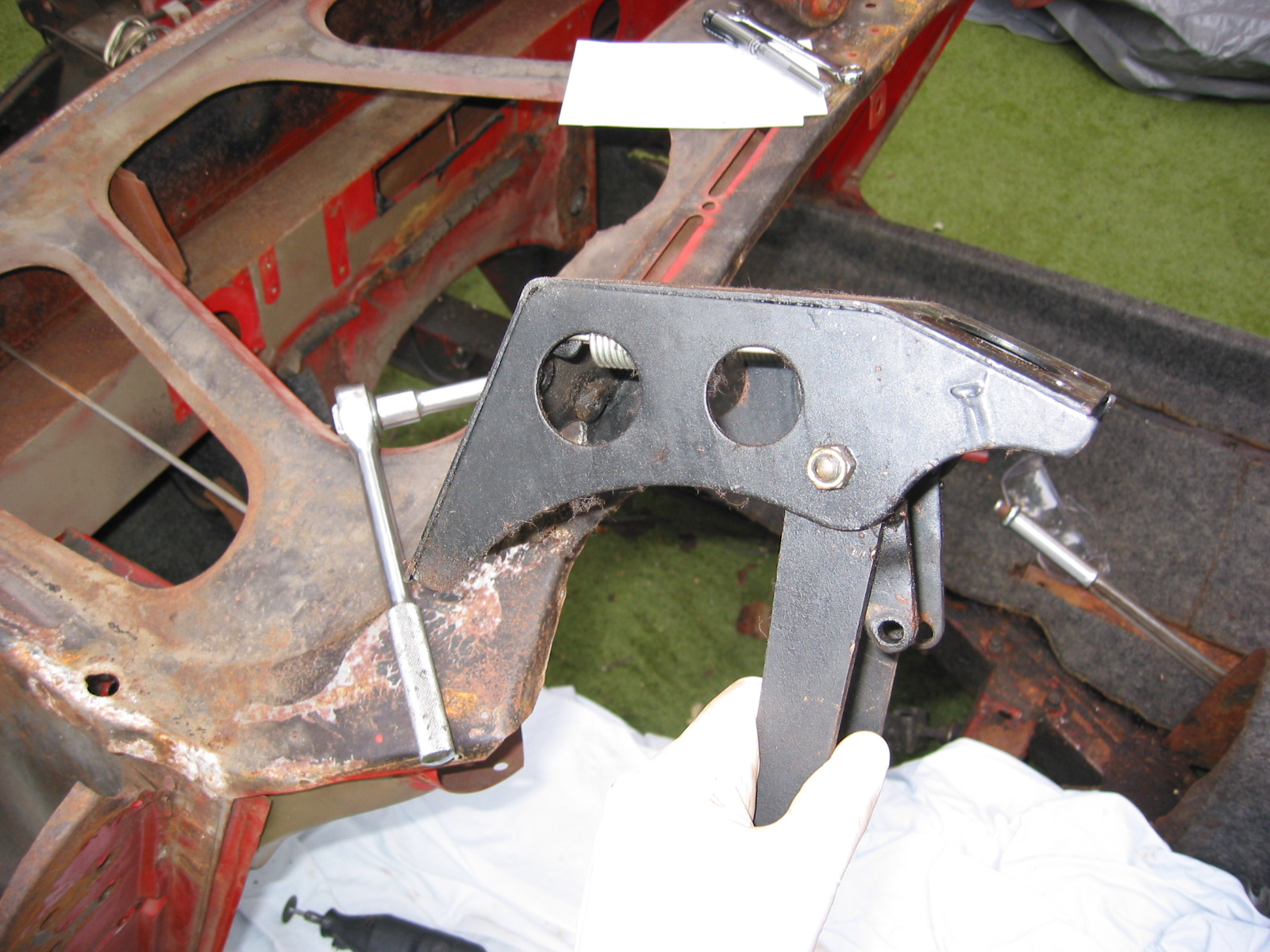
The brake pedal brake switch is a custom addition to the Bugeye. Details on the switch and its mounting bracket are highlighted in another post: https://valvechatter.com/?p=14351
Two wires from the harness, a green wire and a dark green/orange wire, come through the grommet in the LH footbox near the dipper switch and connect to the switch at the pedal.
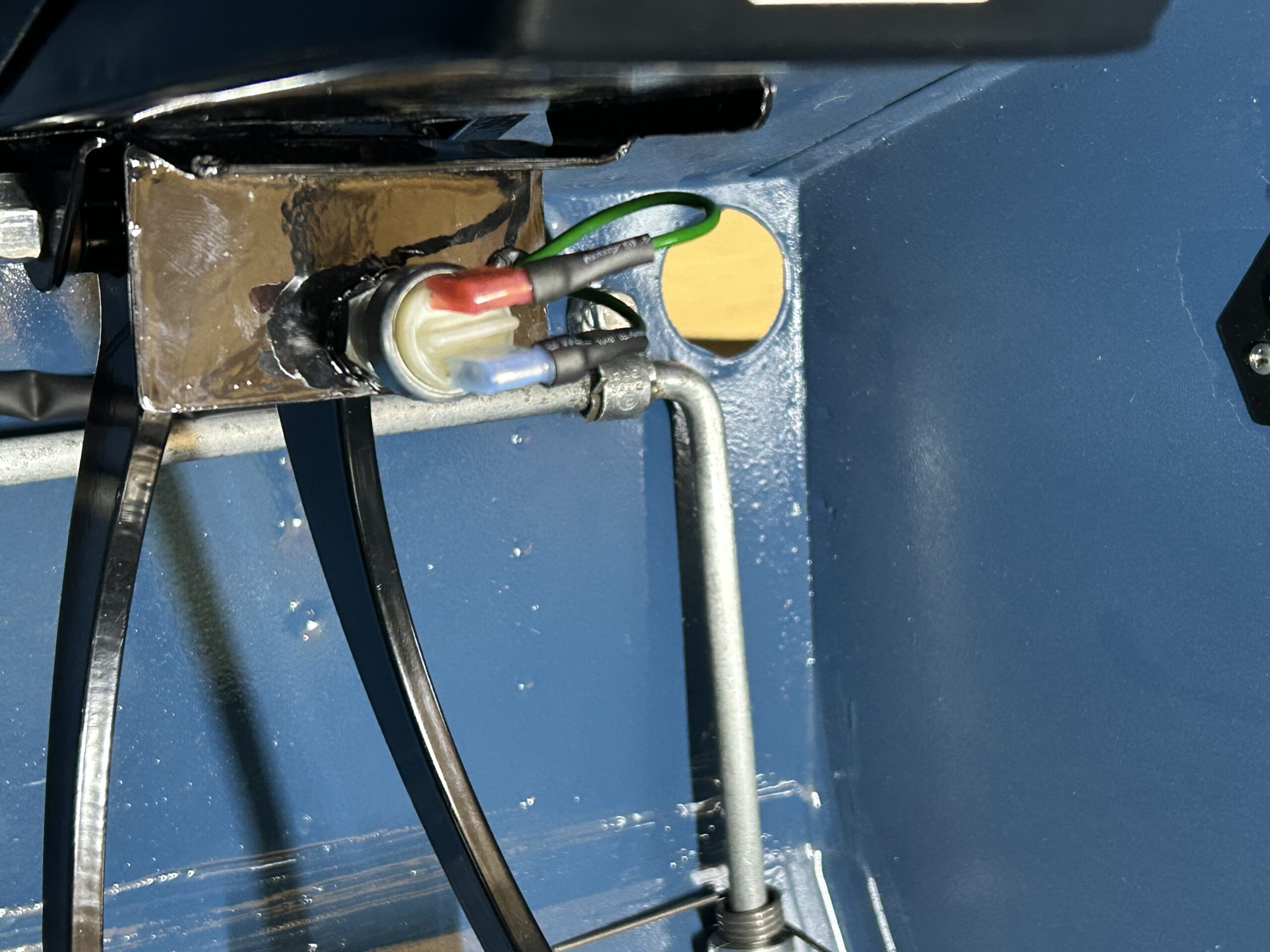
Brake Pedal brake switch wiring
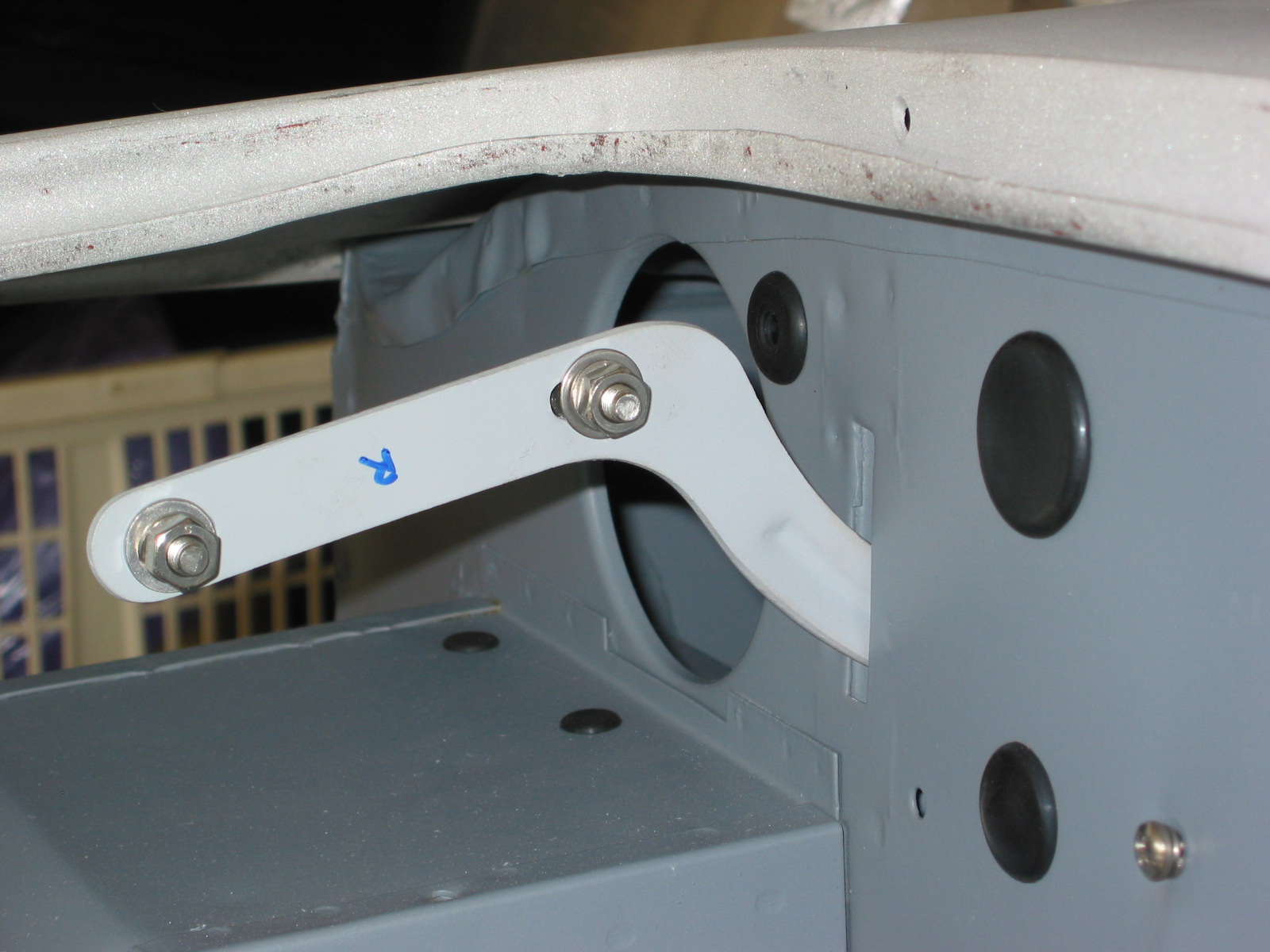
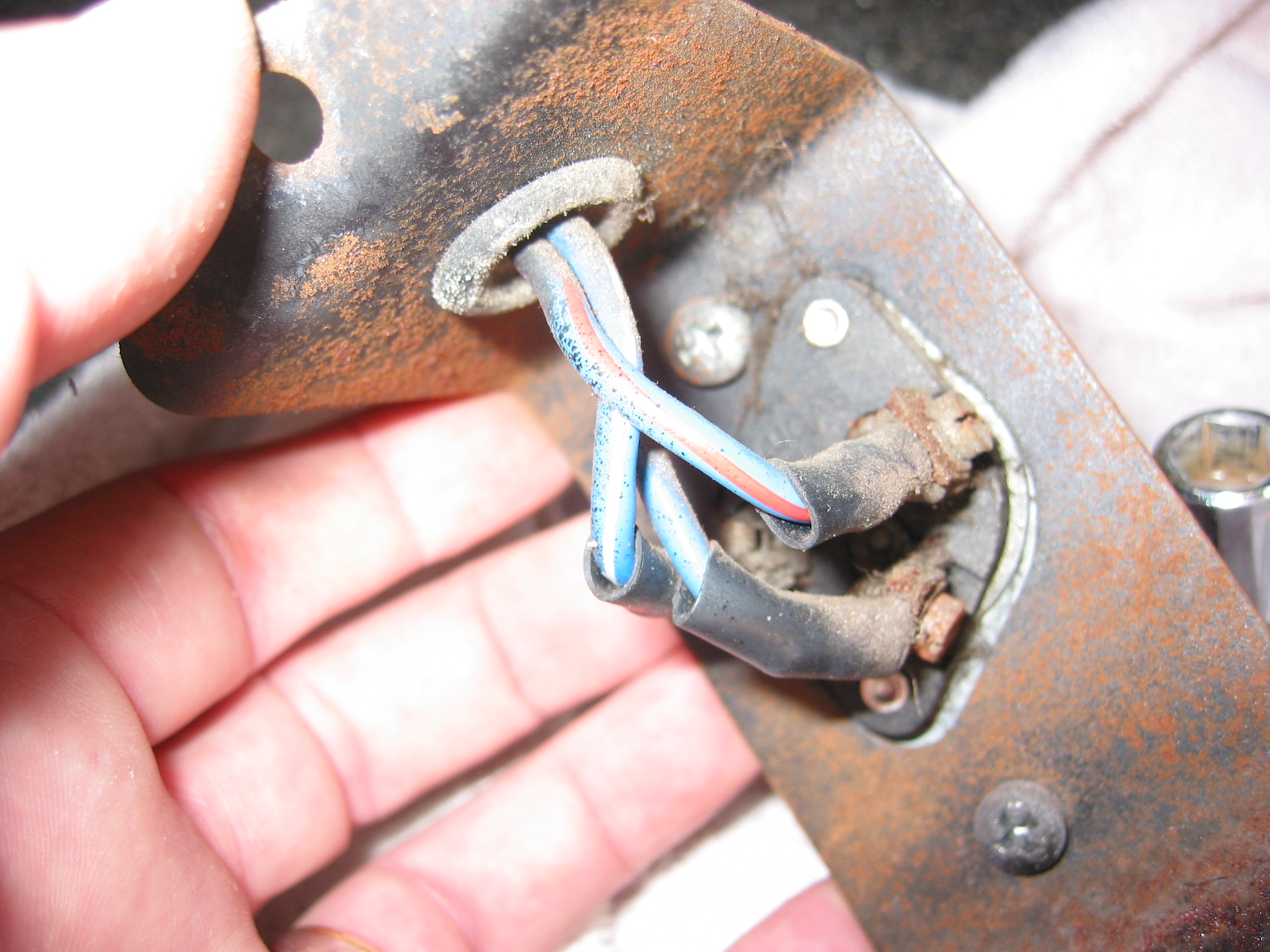
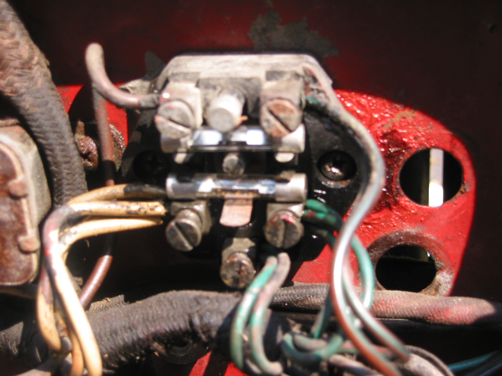
The Dipper switch wiring was completed next. We had a little issue on this because we cut two of the wires a little too short requiring the use of bullet connectors to add length to the wiring to the switch. However, while space was tight, we were able to make all of the necessary connections.
There are three terminals on the dipper switch. A power-in terminal, a low-beam terminal, and a high-beam terminal. One has to look closely to find it but the power-in terminal is marked with an arrow on the switch molding. The blue wire from the harness connects to this terminal via a bullet connector.
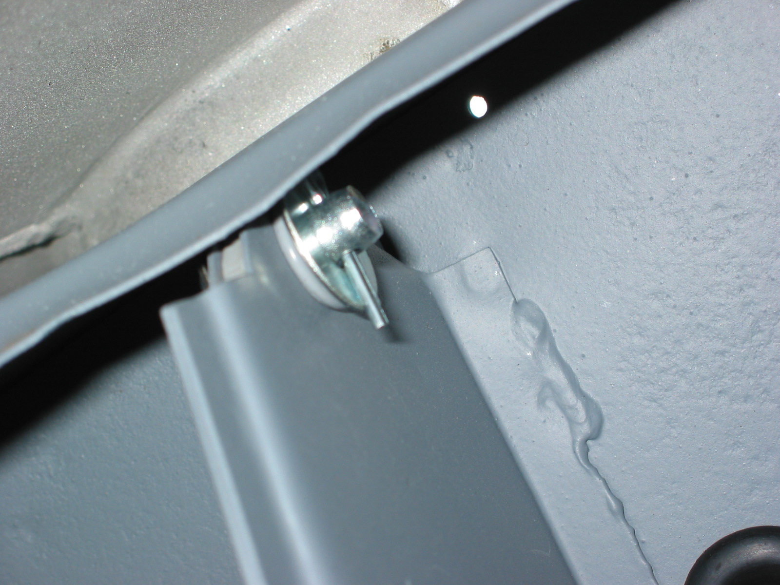
The blue/red wire is connected via a bullet connector to a blue/green wire (ran out of blue/red) and then to one of the remaining switch terminals – it doesn’t matter which one.
Three wires connect to the remaining terminal on the switch. The blue/white wire is for high beam operation, the green wire is for the high beam warning light in the speedometer, and the blue/yellow wire is routed to the toggle switch under the dash for the driving lights. These three wires connect together via a four way bullet connector, with one blue/yellow wire then connecting to the terminal on the switch. A bit confusing, but the photo helps.
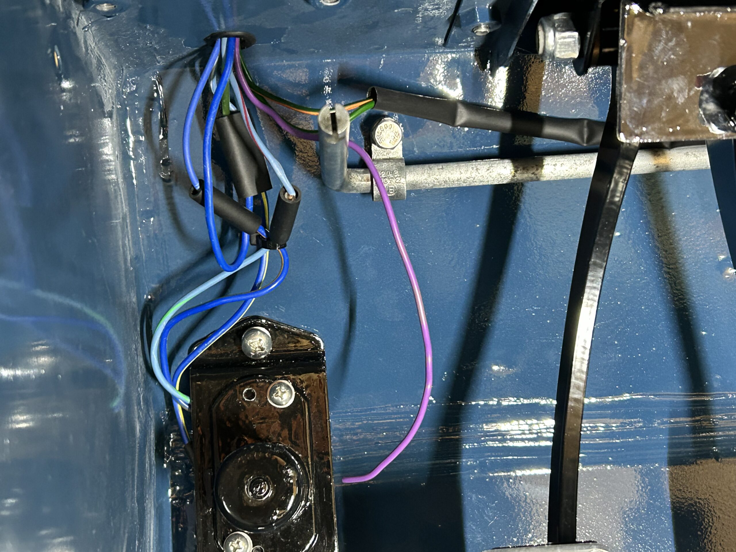
Dipper switch wiring
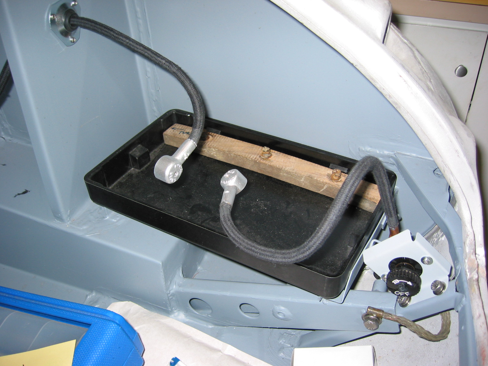
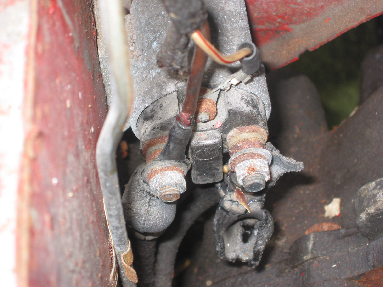
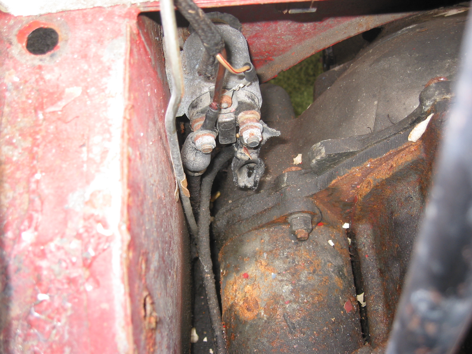
The fuel pump wiring connections were then made. The teal/purple wire from the harness was connected to the black wire at the Facet pump with a spade connector, and the white/purple wire from the harness was connected to the SU pump with a spade connector
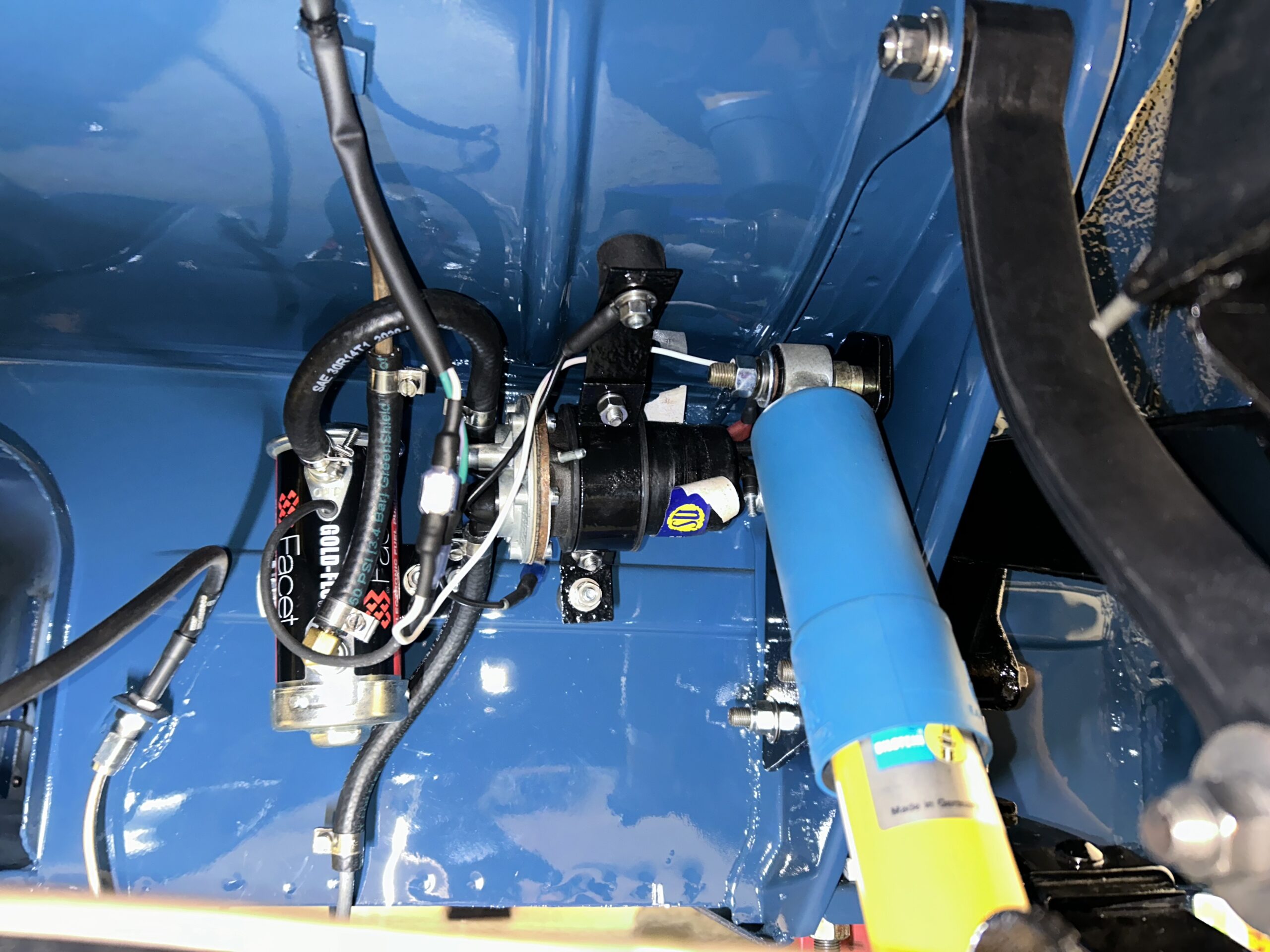
Dual fuel pumps wiring connections
Bugeye Restoration Video Episode Eighty shows the installation of the front and rear harnesses: https://vimeo.com/998221034/30174c4eea?share=copy
The contents of this episode include the following:
0:00 – Braided wiring harness received
0:30 – Begin wiring harness installation
0:58 – Power distribution fuse box
1:48 – Fuse ratings
1:58 – Wiring to Classic Technologies fuse box
2:33 – Wiring clips on the RH engine bay valance
2:40 – Deutsch connector for wiring the bonnet
3:30 – Wiring connections to the horns
5:08 – Horns wiring cover
5:30 – Hydraulic brake switch wiring connected
5:45 – Ignition coil wiring connections
6:05 – Heater blower wiring connections
6:26 – Alternator wires to be connected later
6:32 – Connector “F” wiring to the RH courtesy lights and brake lights
7:30 – Brake pedal brake switch wiring connections
7:55 – Dipper Switch wiring bracket
8:54 – Brake pedal switch wiring tested
9:02 – Accelerator pedal assembly temporary installation
9:20 – Wiper controller installation
9:30 – RH demister elbow and tubing installation
10:30 – Wiring harness to the rear of the car installed
11:18 – Fuel pumps wiring connections