Fellow Healey enthusiast, Charlie Hart has come up with several “customizations” over the years to “improve” on the original Austin-Healey design. He then makes these available to the Healey community. One of those items is a fuse panel that mounts to the firewall in the same manner and place as the original. The panel has seven fuses with a total of fourteen terminals. Two of these are unswitched – direct feed from battery and twelve are switched – hot when the ignition is turned on.
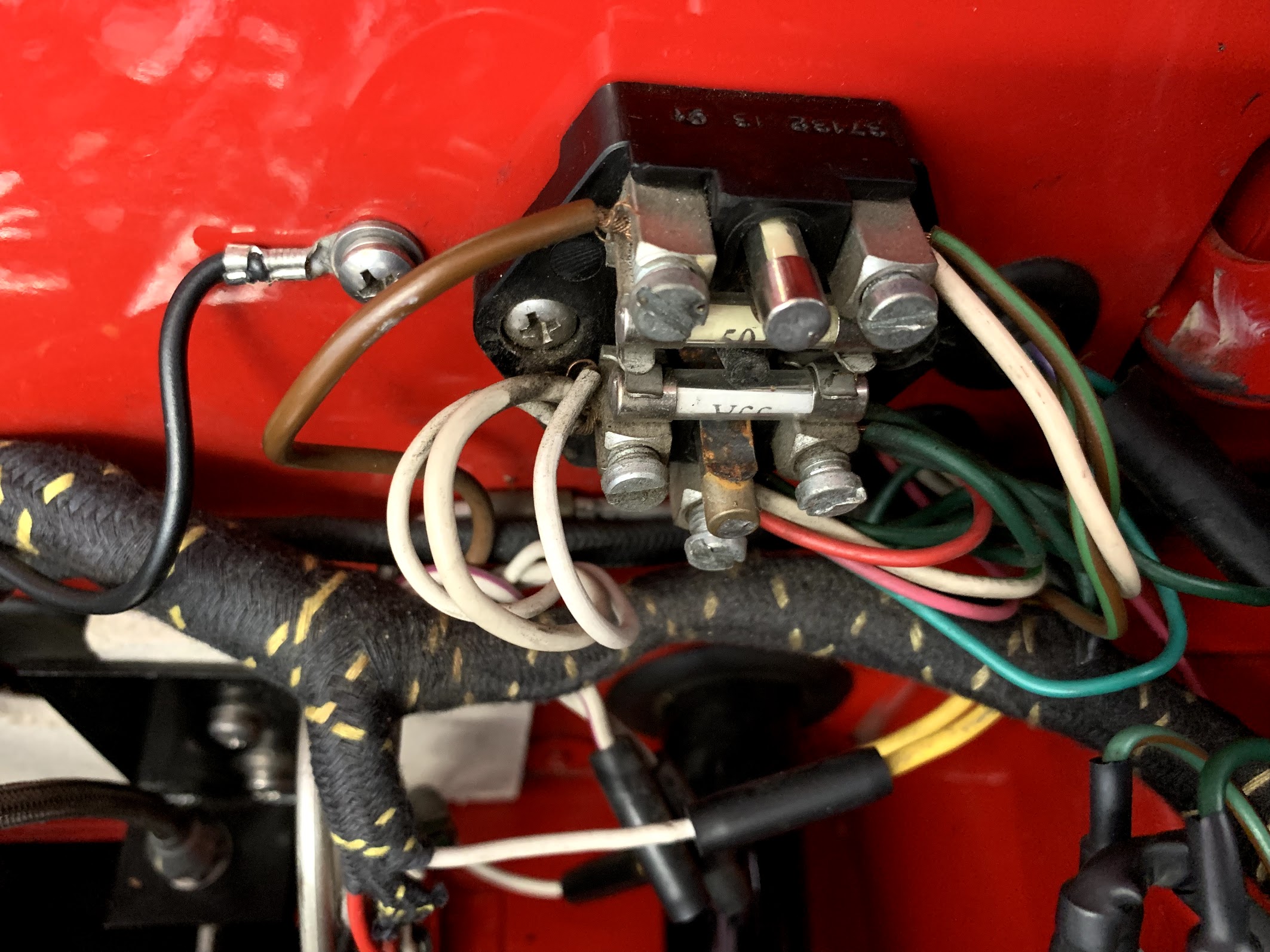
This is the original fuse panel. It was very crowded with the electrical enhancements I have on my car – cruise control, extra fresh air blower, extra under dash three fuse fuse panel, intermittent wiper control, beeper for turn signals and a sound system. If I had a failure in one of these circuits it would be difficult to assess given the small number of fused circuits.
Original Fuse Block
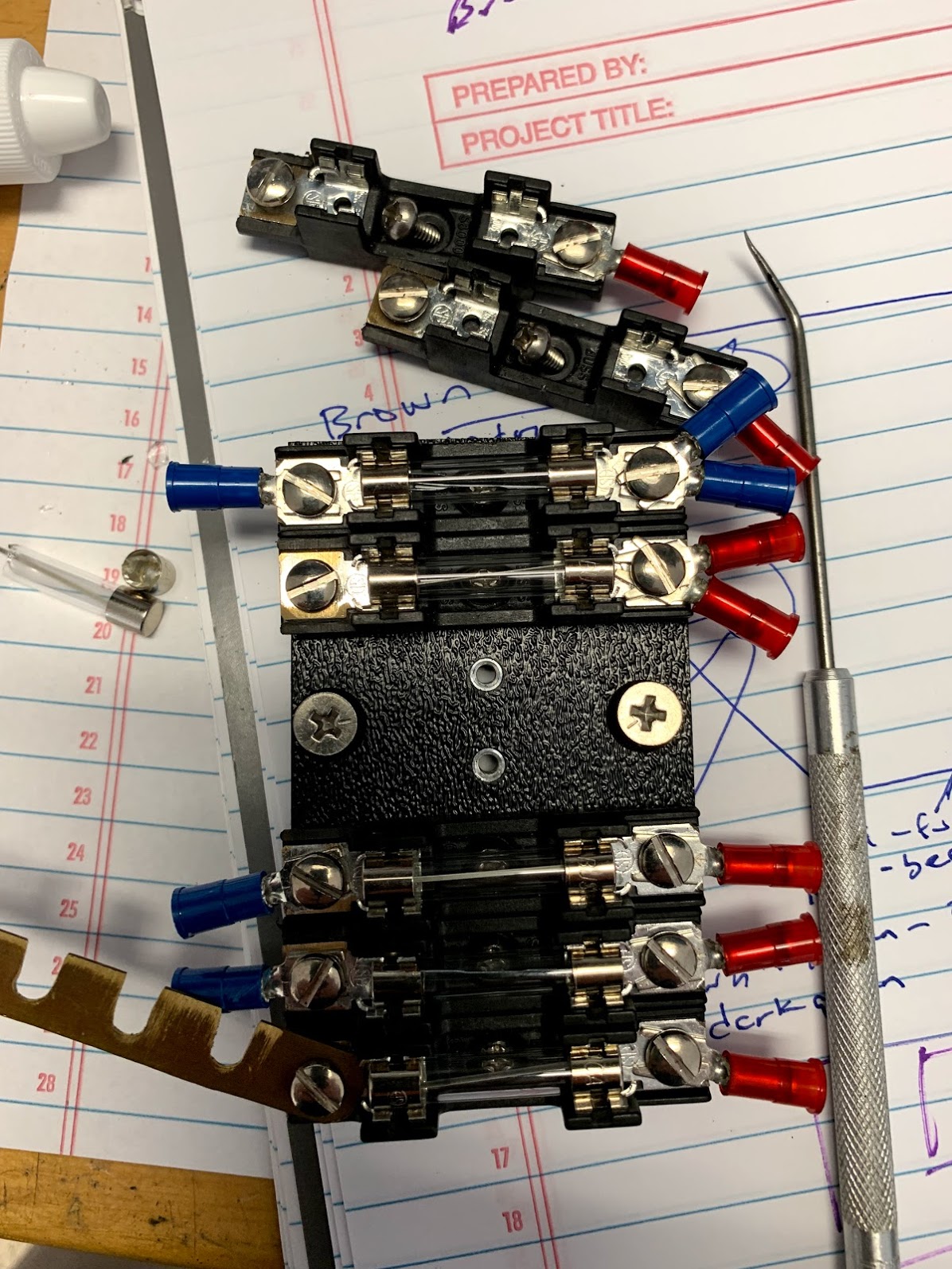
Charlie’s fuse panel is comprised of a number of individual fuse blocks that are screwed into a flat piece of pvc, and came complete with wire connectors and a sample wiring diagram based on an original unmolested car.
Charlie Hart Fuse Panel
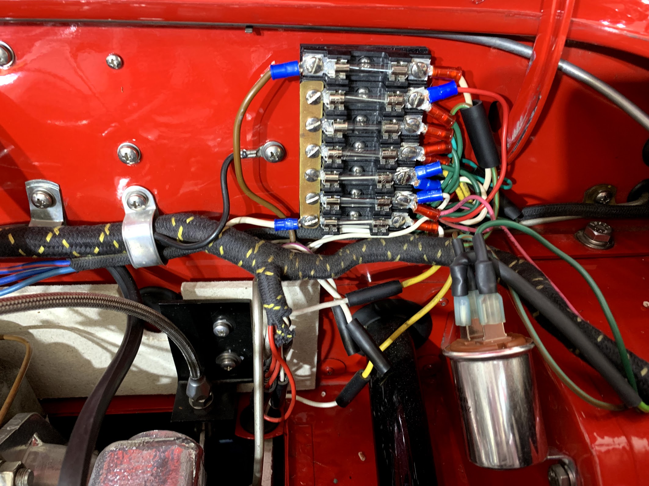
This is a photo of the panel installed with connections made. I still had to double load some of the connection points but circuit segregation is much better than it was before!
Charlie Hart Fuse Panel Installed
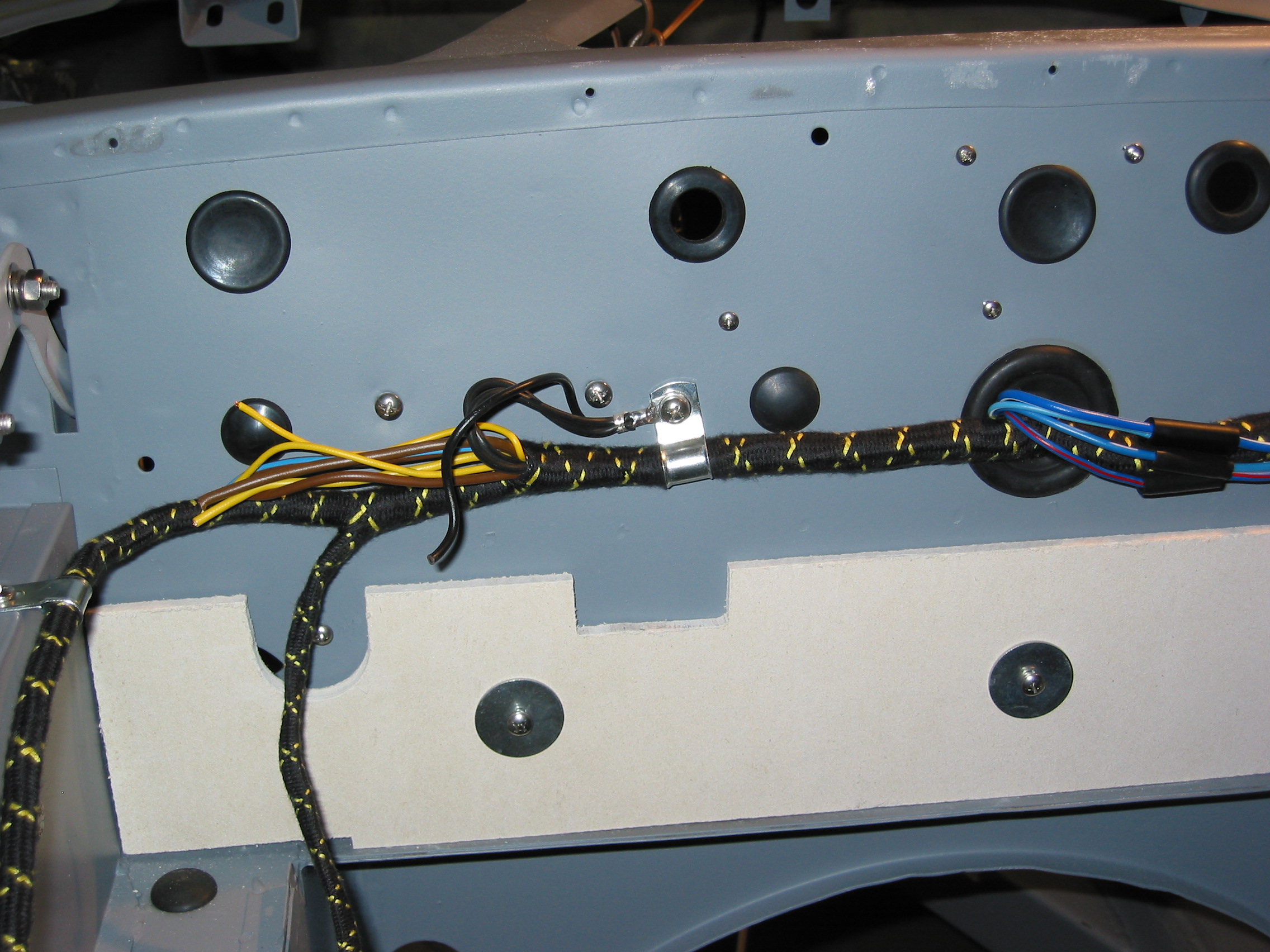
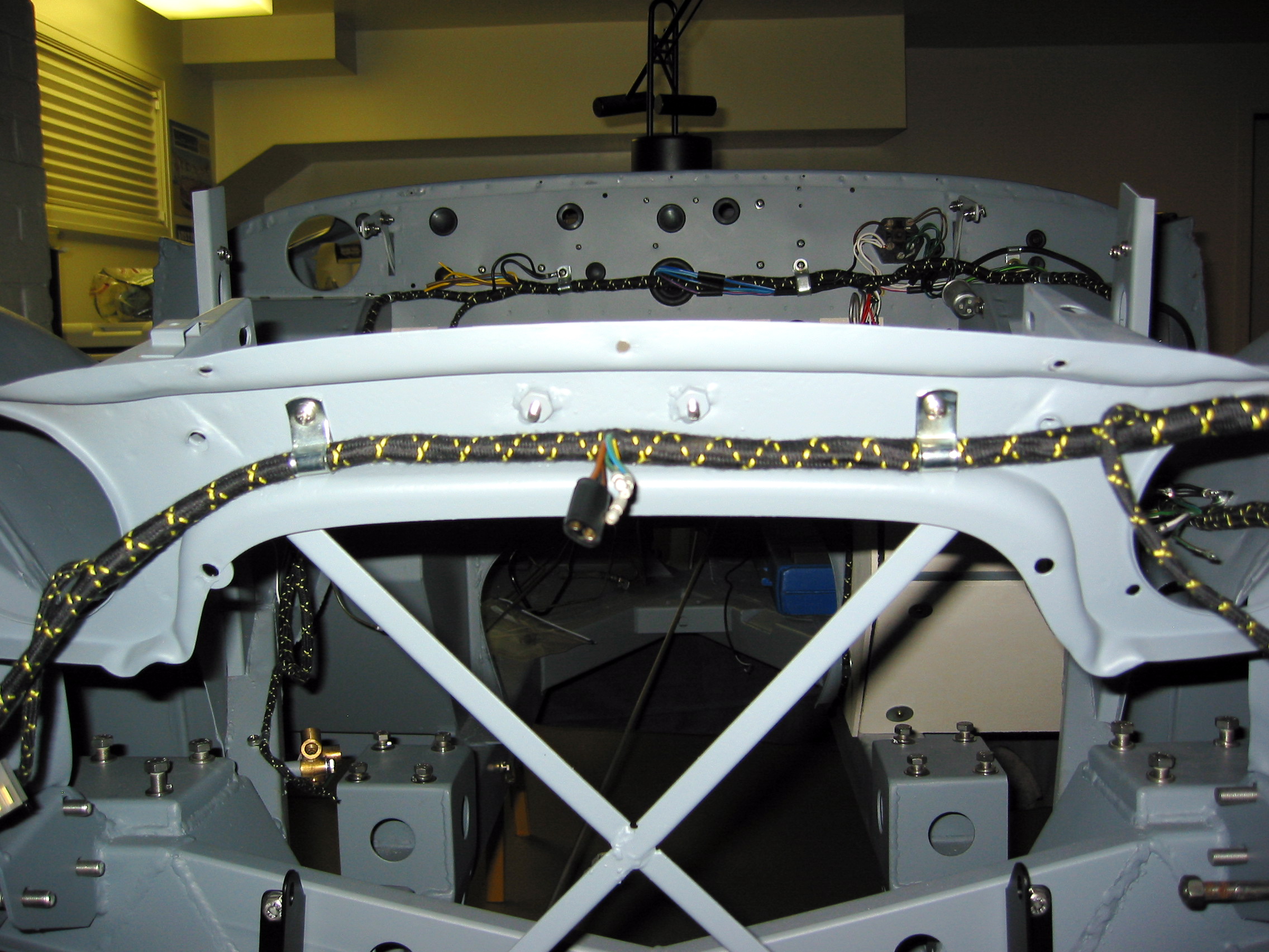
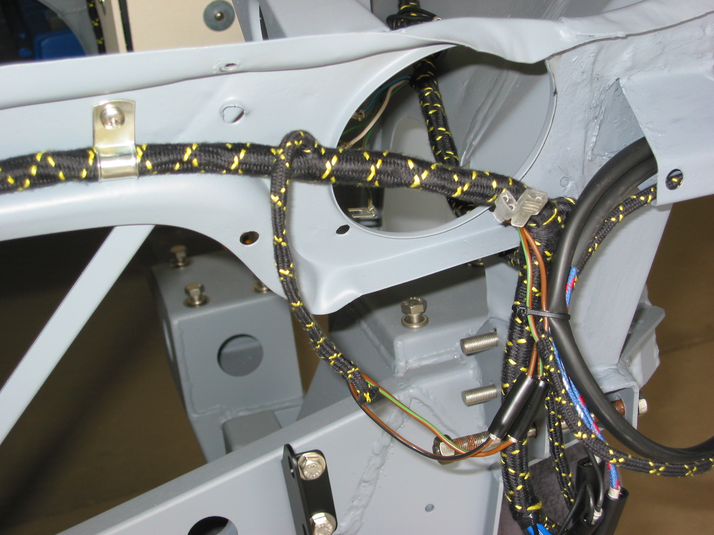
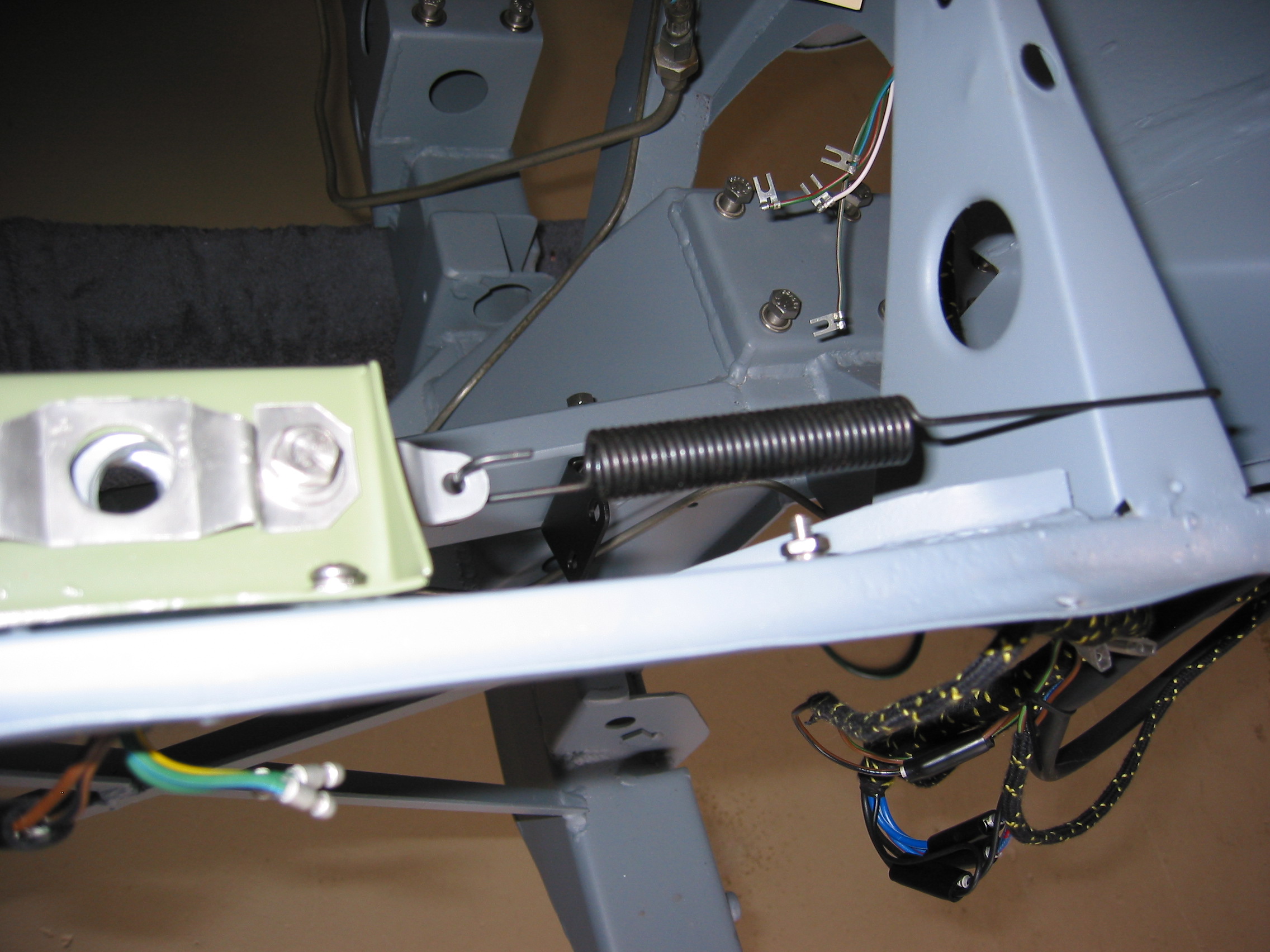
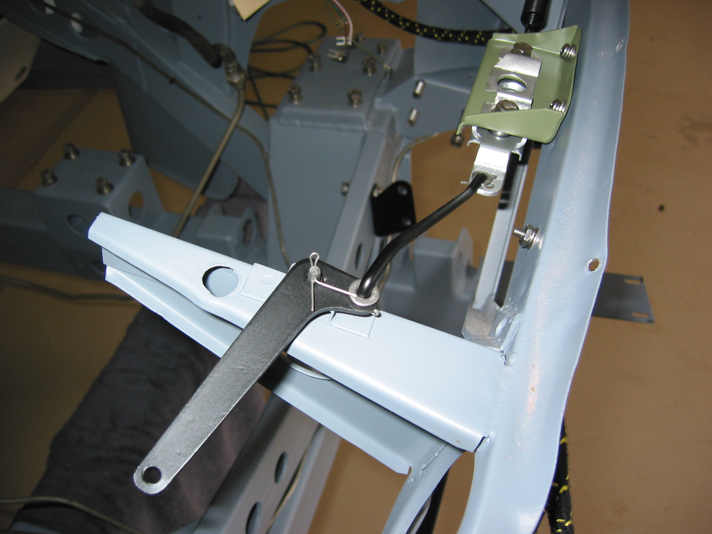
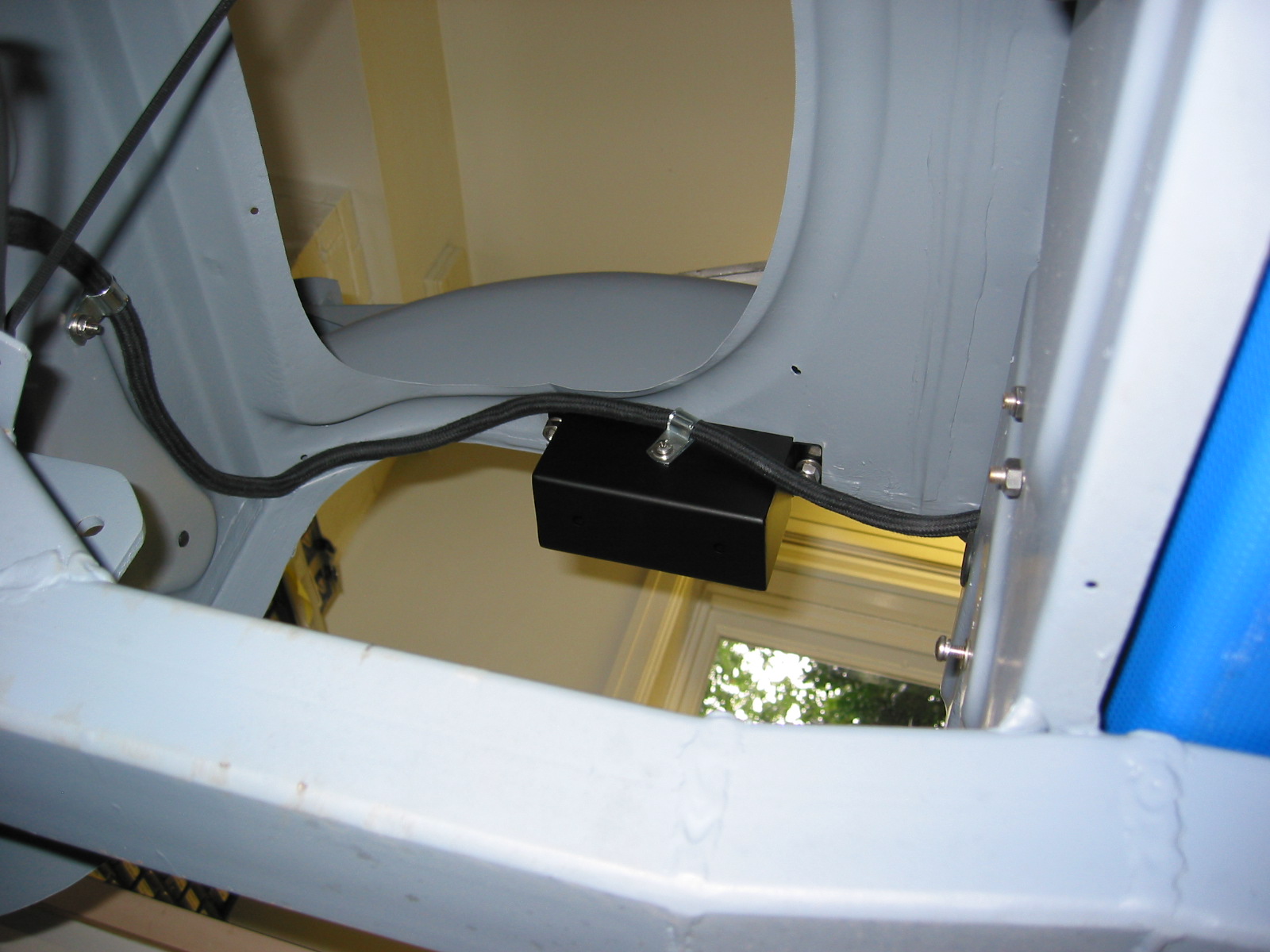
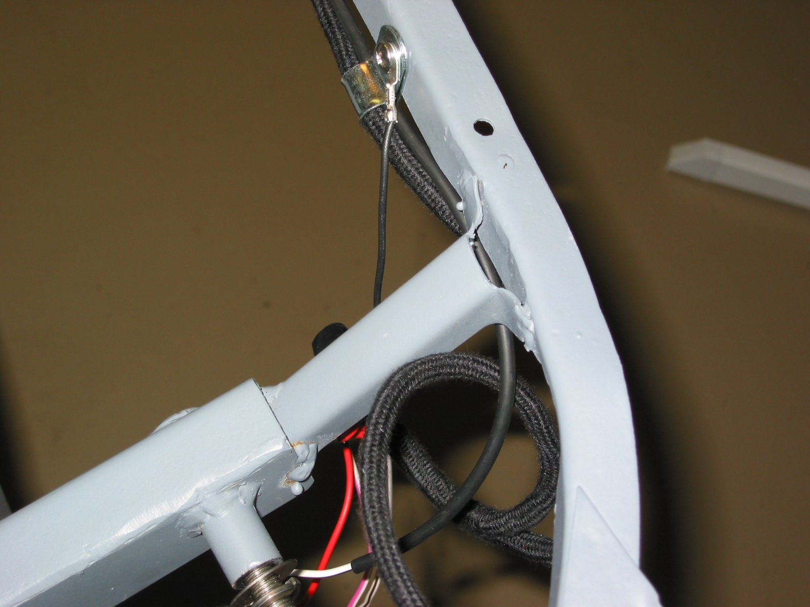
This is an image of the actual wiring to the fuse panel in the Bloody Beast:
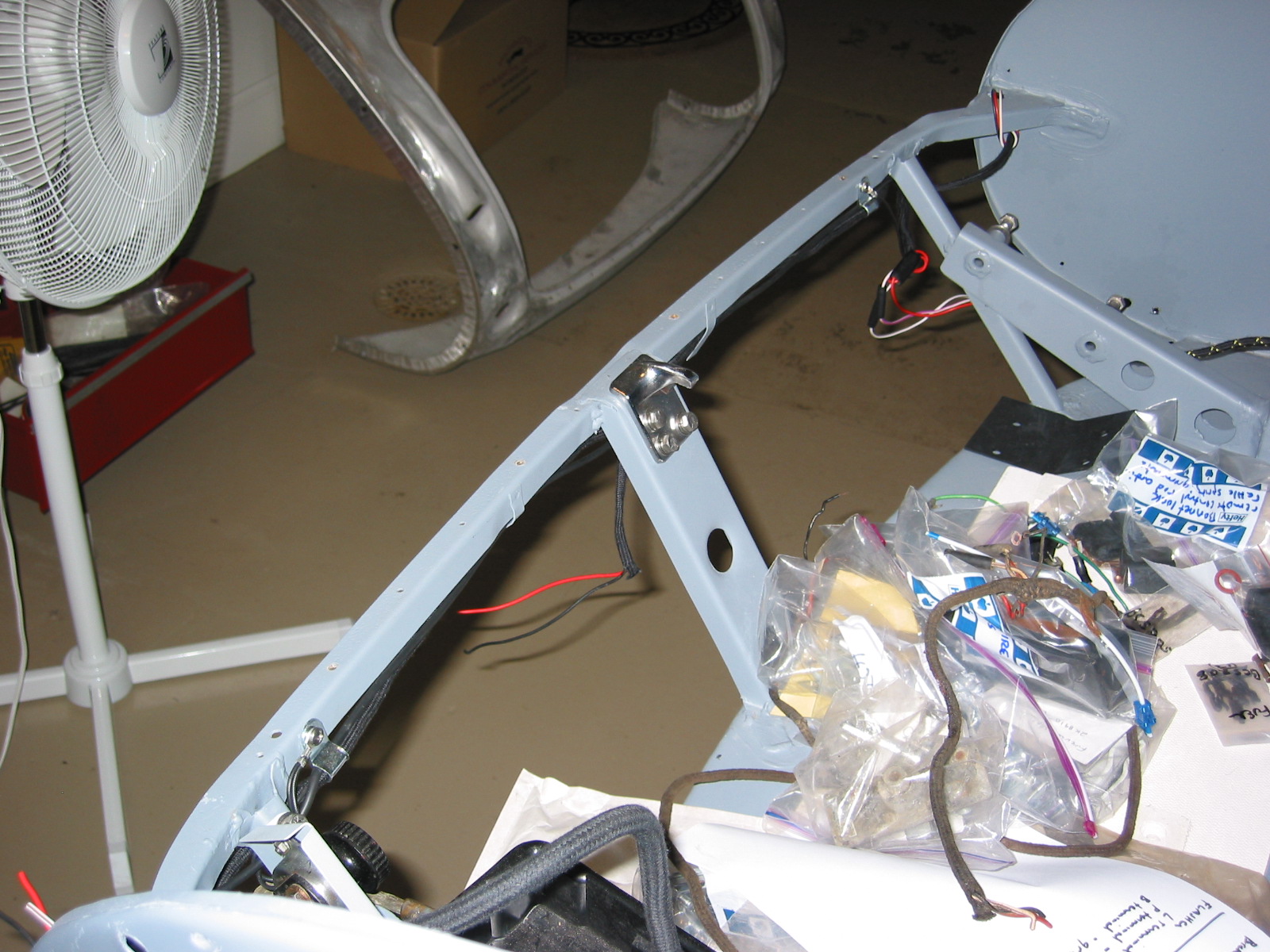
Wiring Harness – Received the new wiring harness from British Wiring Inc. We ordered the main harness, horn wiring that we probably won’t need, light pigtails and the stator tube wiring. Everything looked good. Also ordered a special pliers for pushing the wiring bullet connectors into the rubber joints which will prove to be a real time saver.
After taking the harness through the firewall, the major components were separated to go down the two sides of the car.
Flasher – First connected the three wires to the flasher – green, light green, and green/brown.
Wiper Harness – Then connected the wiper harness with connectors and fed it through the firewall – black, black/green, and green.
Dimmer Switch – The wires for the dimmer switch were then connected and fed through the top of the footbox and connected to the switch – blue/red, light blue, and blue/white.
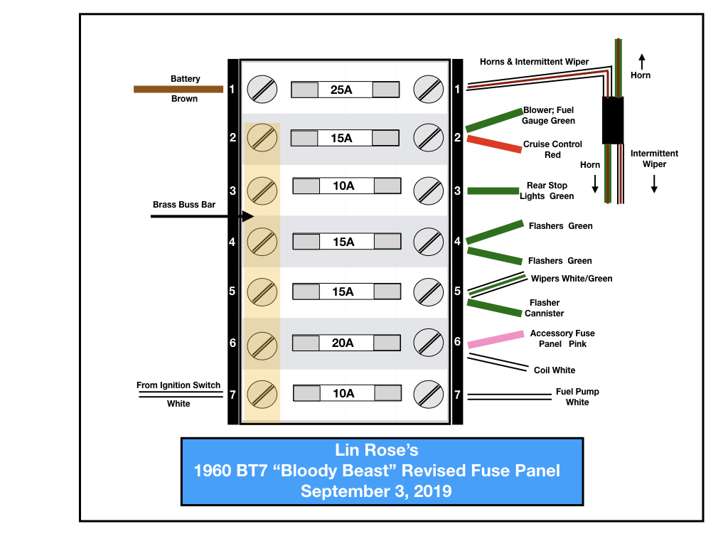
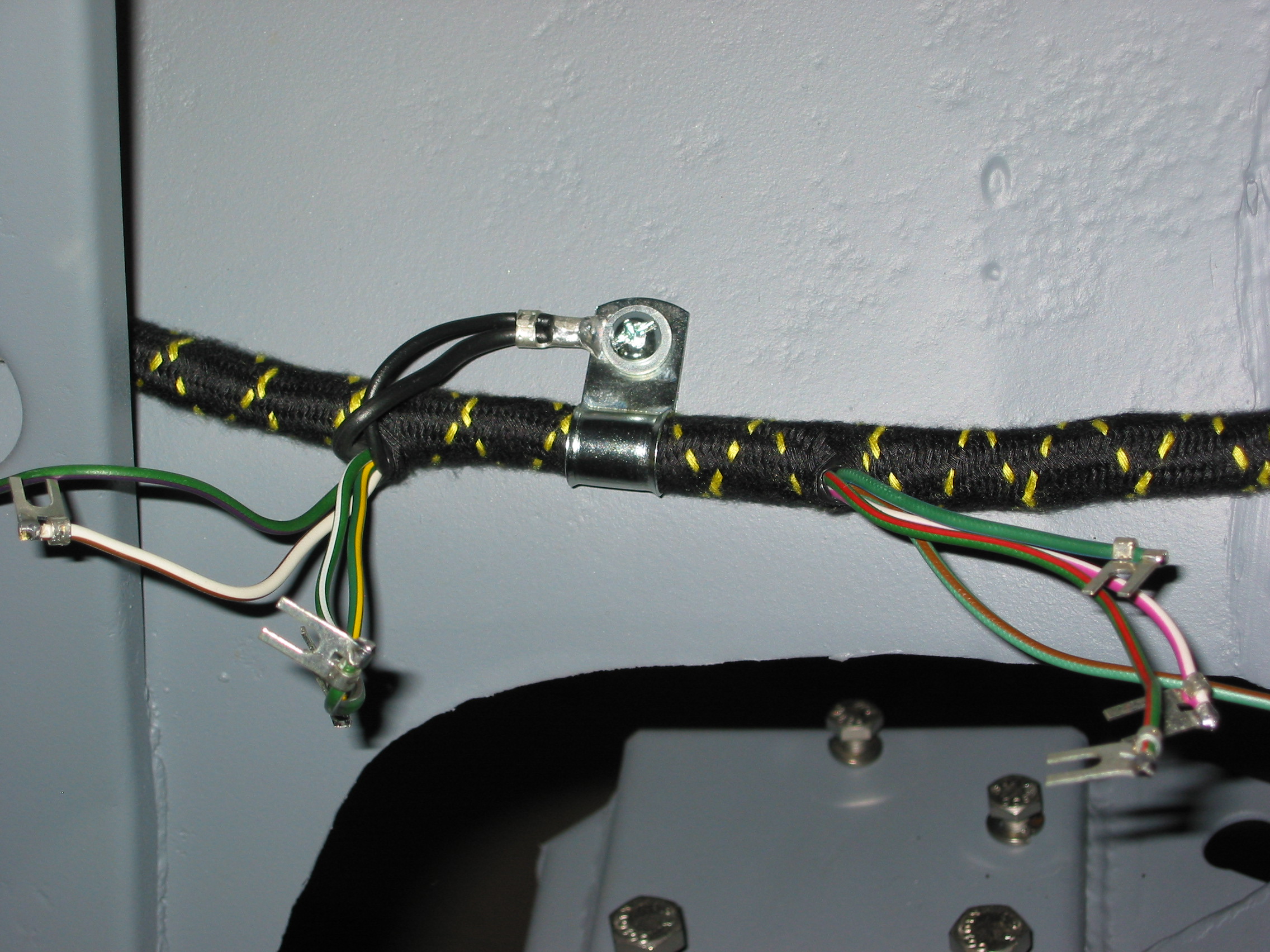
Fuse Panel – Wiring was then connected from the harness to the fuse box. Three white wires to the lower left terminal; one heavy brown wire to the top left terminal; two brown/green wires to the upper right terminal; and five green wires to the lower right terminals.
Throttle Switch – The white and white/purple wires intended for the throttle switch will not be used so rubber connectors were placed on the ends to avoid contact with metal. The wires were tucked below the fuse box.
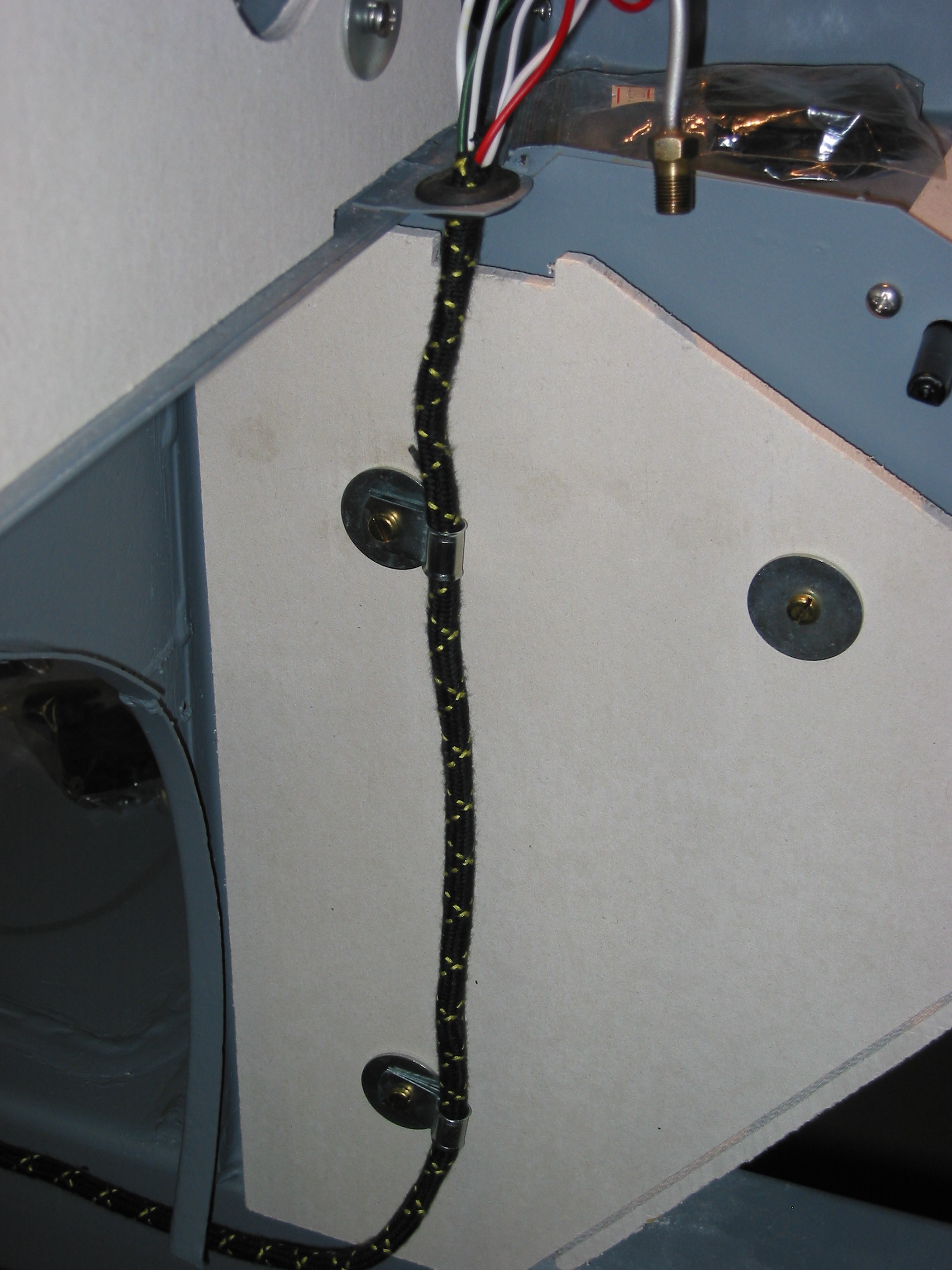
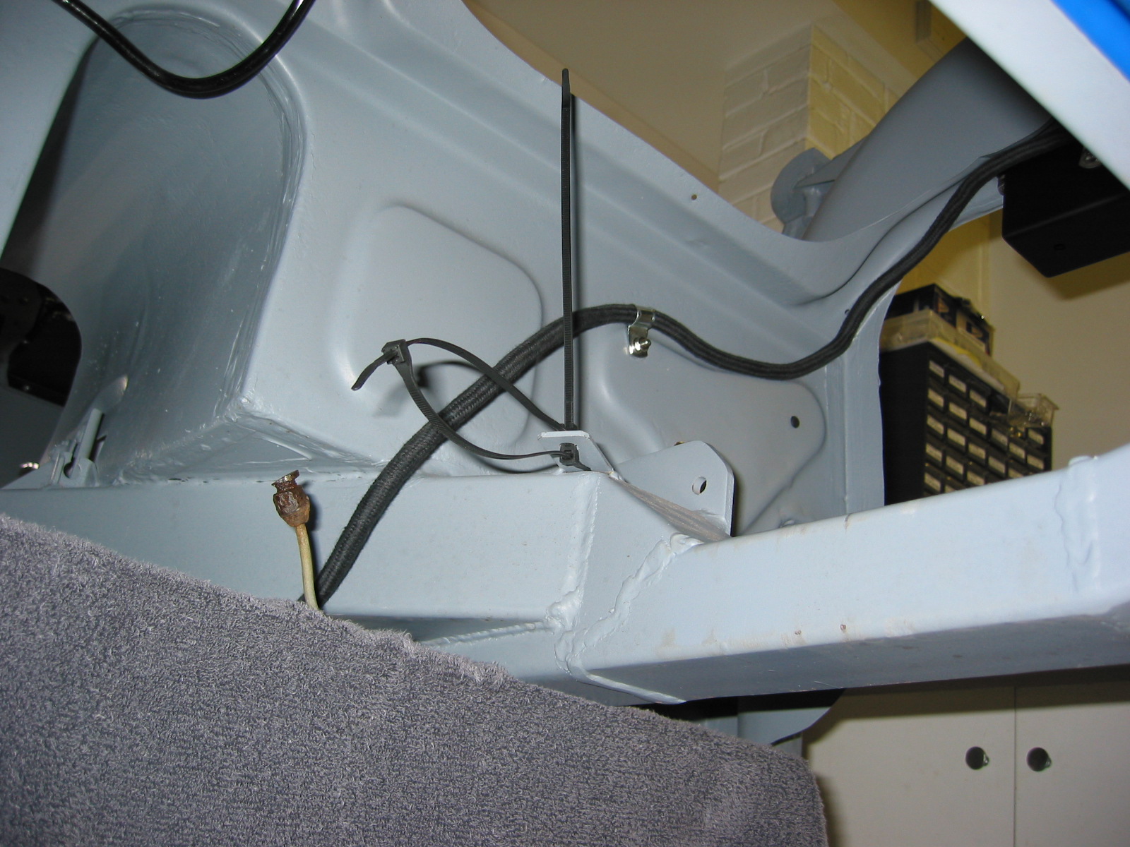
Boot Harness Extension – Six wires were then connected from the firewall harness to the harness that goes to the fuel pump and boot for the lights. The harness runs down the footbox insulation panel with two clips. The harness was clipped to the master cylinder box and then taken through the welded clip on the wheel well.
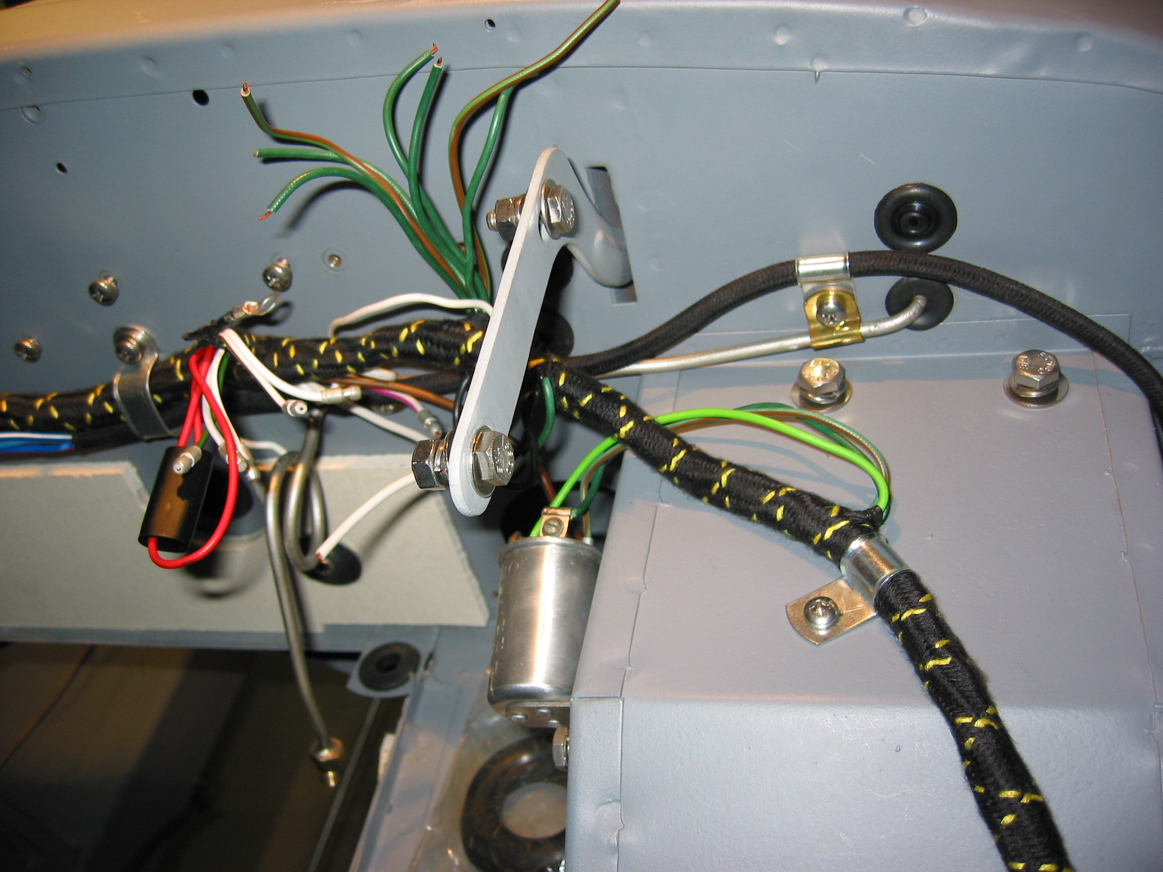
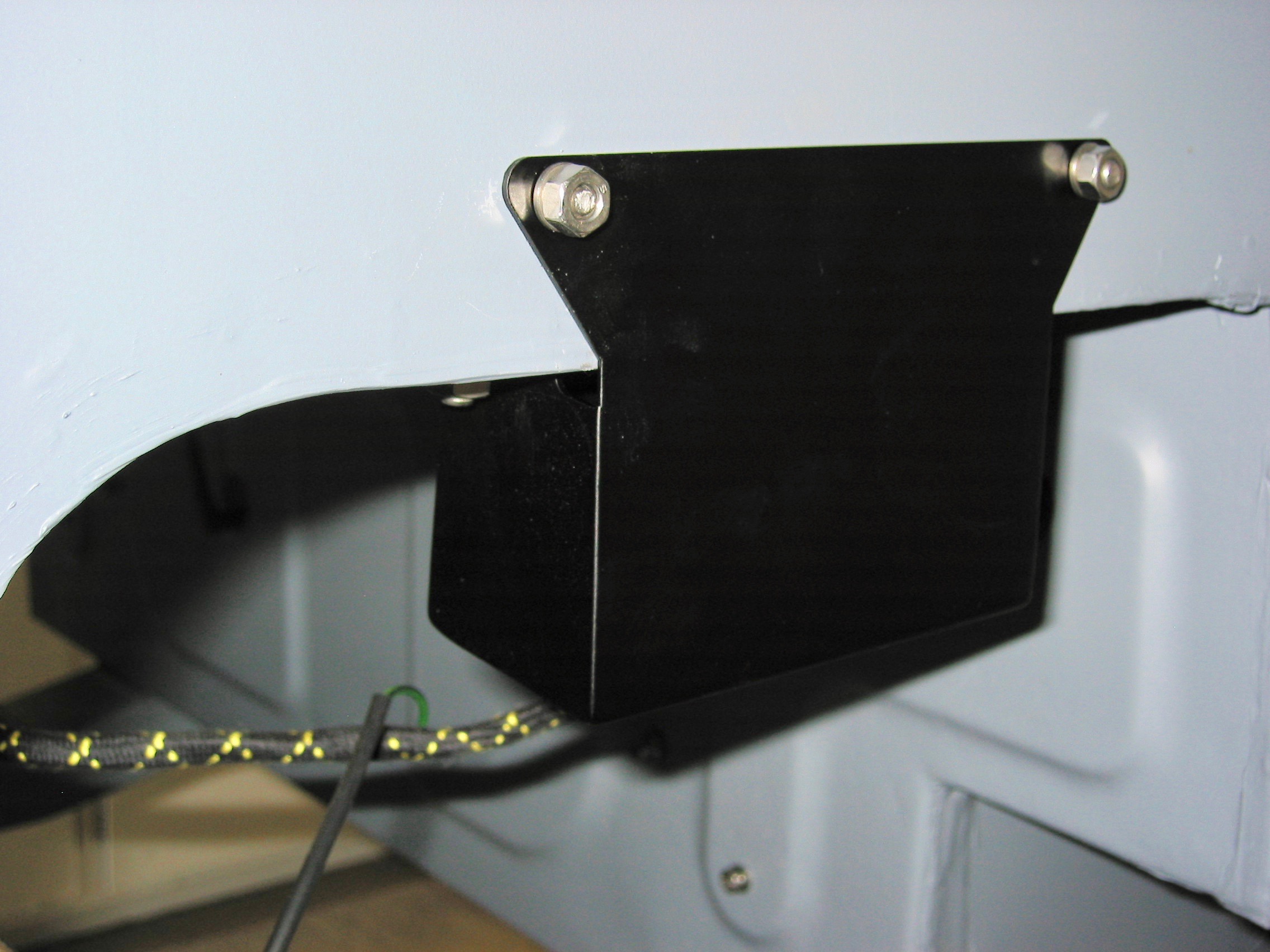
Flasher Relay Box – Wires on the left side will then be connected to the flasher relay box including a black ground wire at the base of the box.
Lights and Horns – The wires were routed to the front of the superstructure for the lights and the horns.
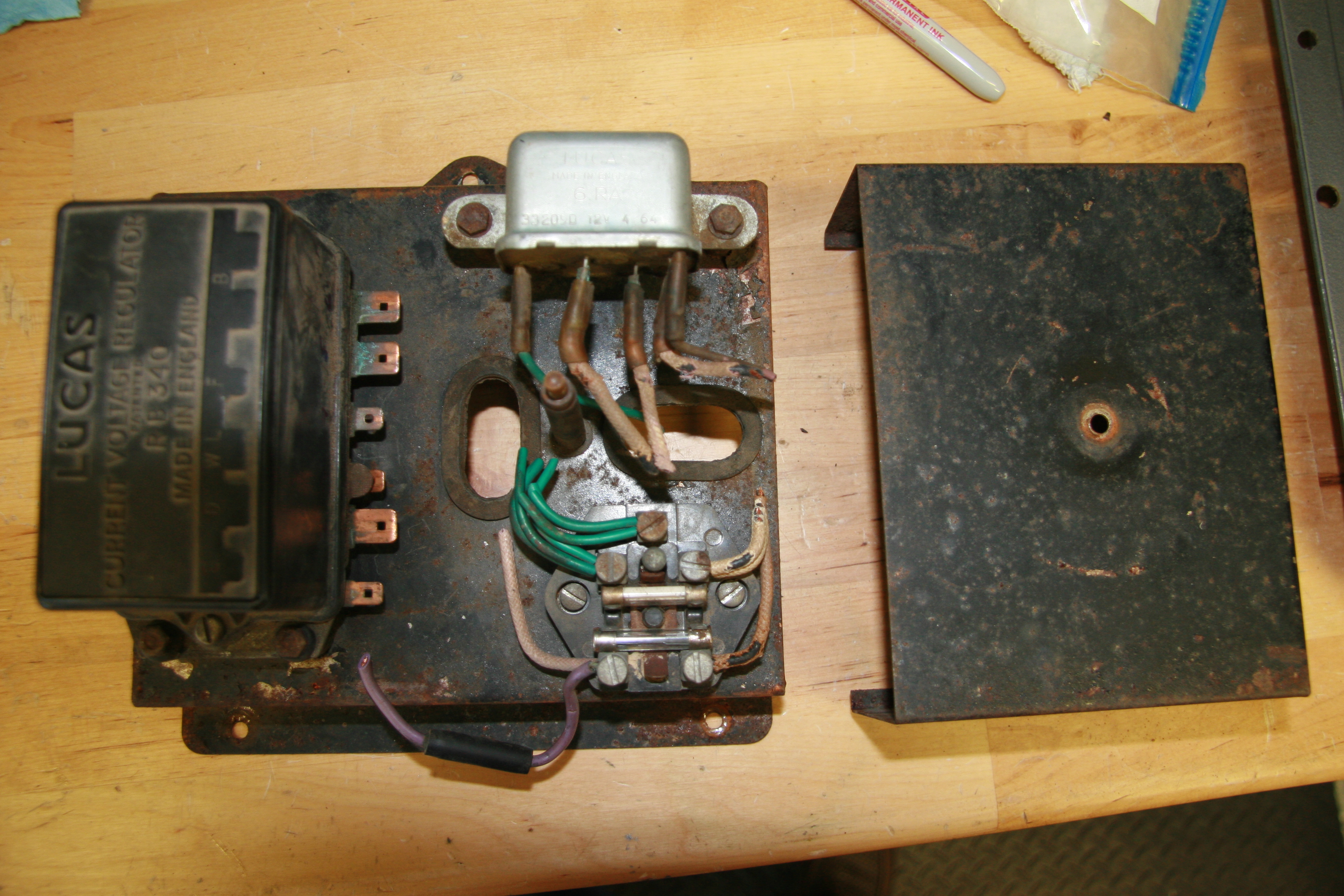
Voltage Regulator Box and Brake Light Switch – The harness was also routed down the right side, by the voltage box and down the right side to the brake light switch.
Wiring 3
Wiring 1
Wiring Fuse Block 2
Wiring 6
Wiring 8
Wiring 9
Wiring 12
September 9, 2003
Heater Vent Doors – Installed the left and right heater outlet vent door assemblies.
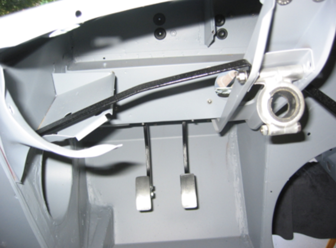
Parcel Tray and Fascia Brackets – Installed parcel tray support bracket and fascia support brace.
Parcel Tray Brace
Fascia Brace
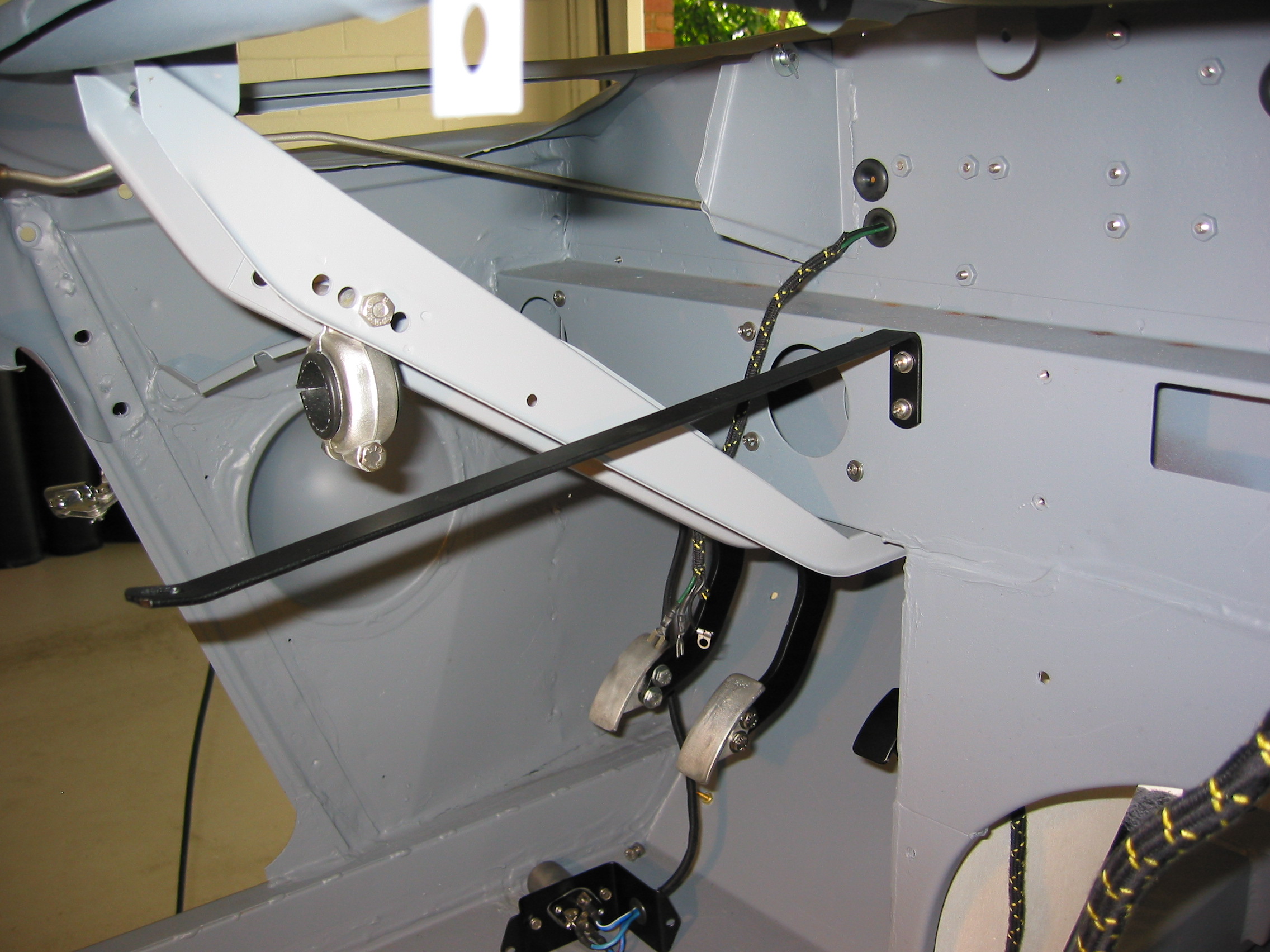
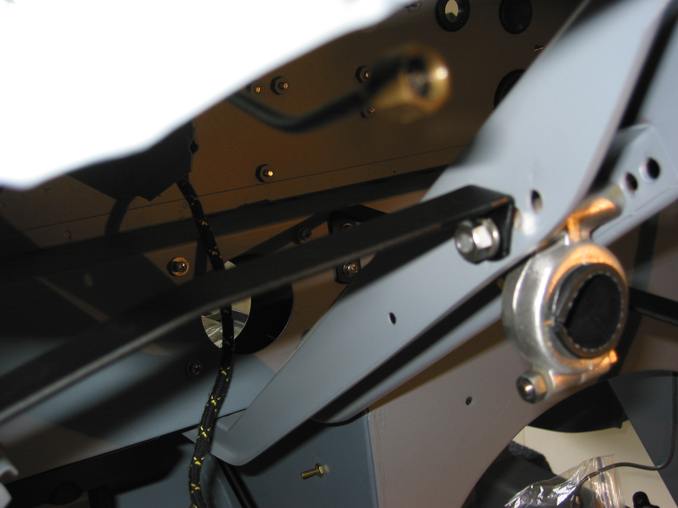
Steering Column Steady Bracket – Installed steering column steady bracket, but unclear about which windscreen post hole it should mount to – will check it out later.
Steering support Brace
Steering Column Steady Bracket 2
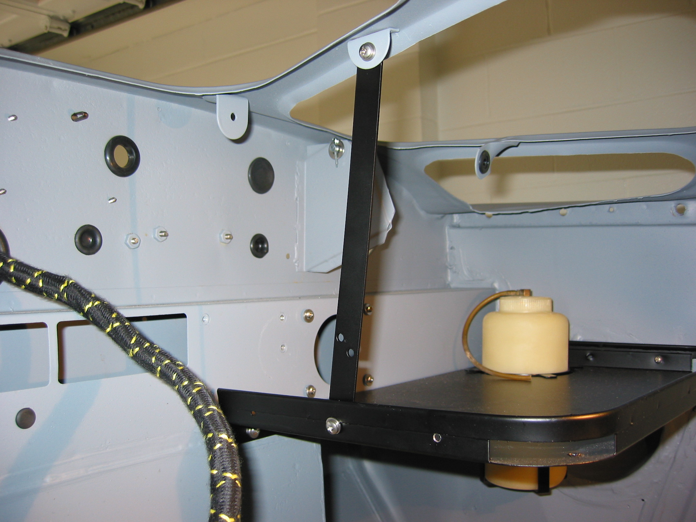
Bonnet Prop Rodand Brake Reservoir Brackets – Installed bonnet prop rod bracket, pivot, and the brake reservoir mounting bracket.
Brake Reservoir Bracket
Bonnet Rod Bracket
Bonnet safety catch and prop rod bracket
Bonnet Latch Bracket and Release Mechanism – Assembled and installed the bonnet latch/release mechanism.
Bonnet Catch painted 4
Bonnet Catch painted 3
Bonnet Catch painted 2
September 13, 2003
Wiring Continued
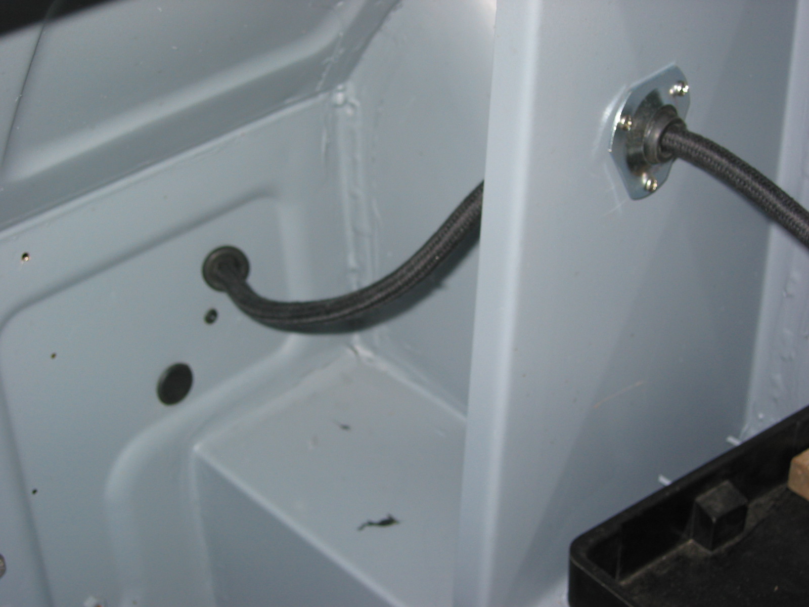
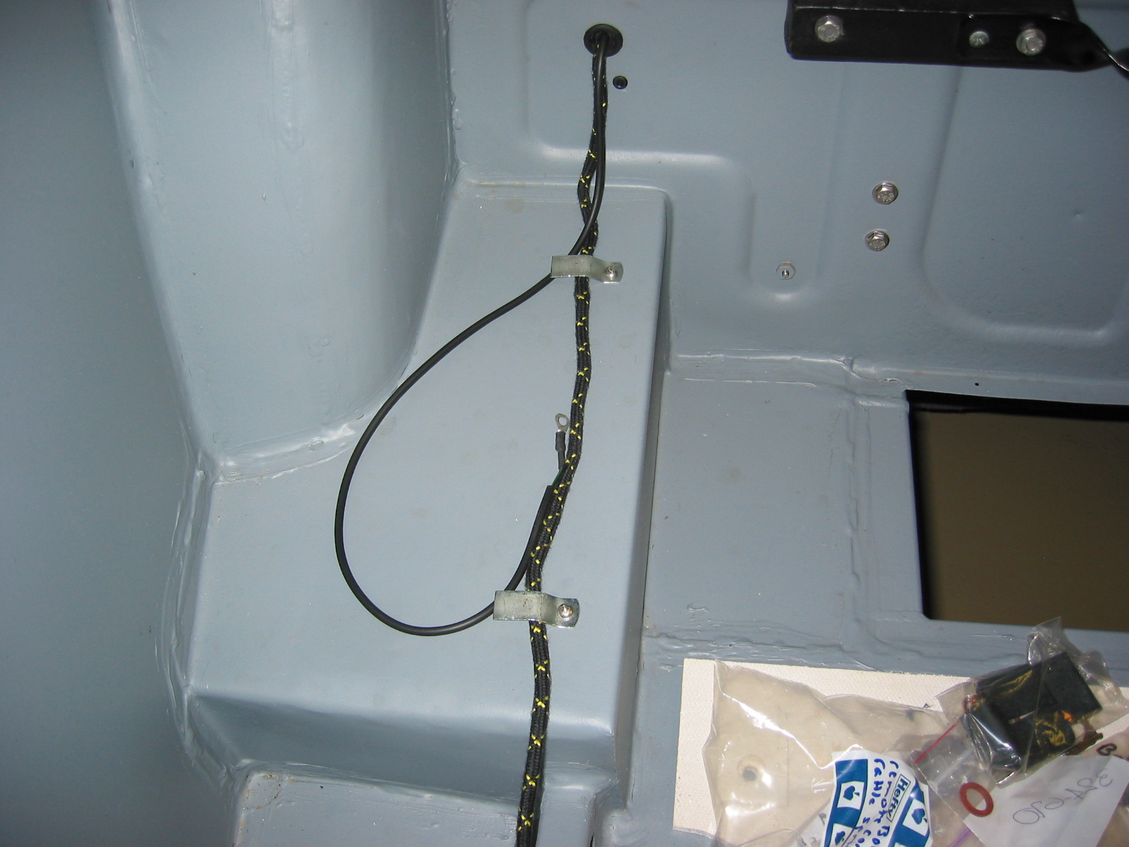
Battery Cable – Installed the battery cable ordered from British Car Specialists. The cable set was expensive, but of high quality. Installed rubber grommets in boot kick panel wall. Clip 1 was attached to the right bump box (Should install the cable on the box before it is mounted on the body.) Clip 2 was attached to the kick panel above the shock mounting bracket. The cable was then routed inside of the right frame rail.
Battery Cable 2
Battery Cable 1
Battery Cable 3
Battery Cable 4
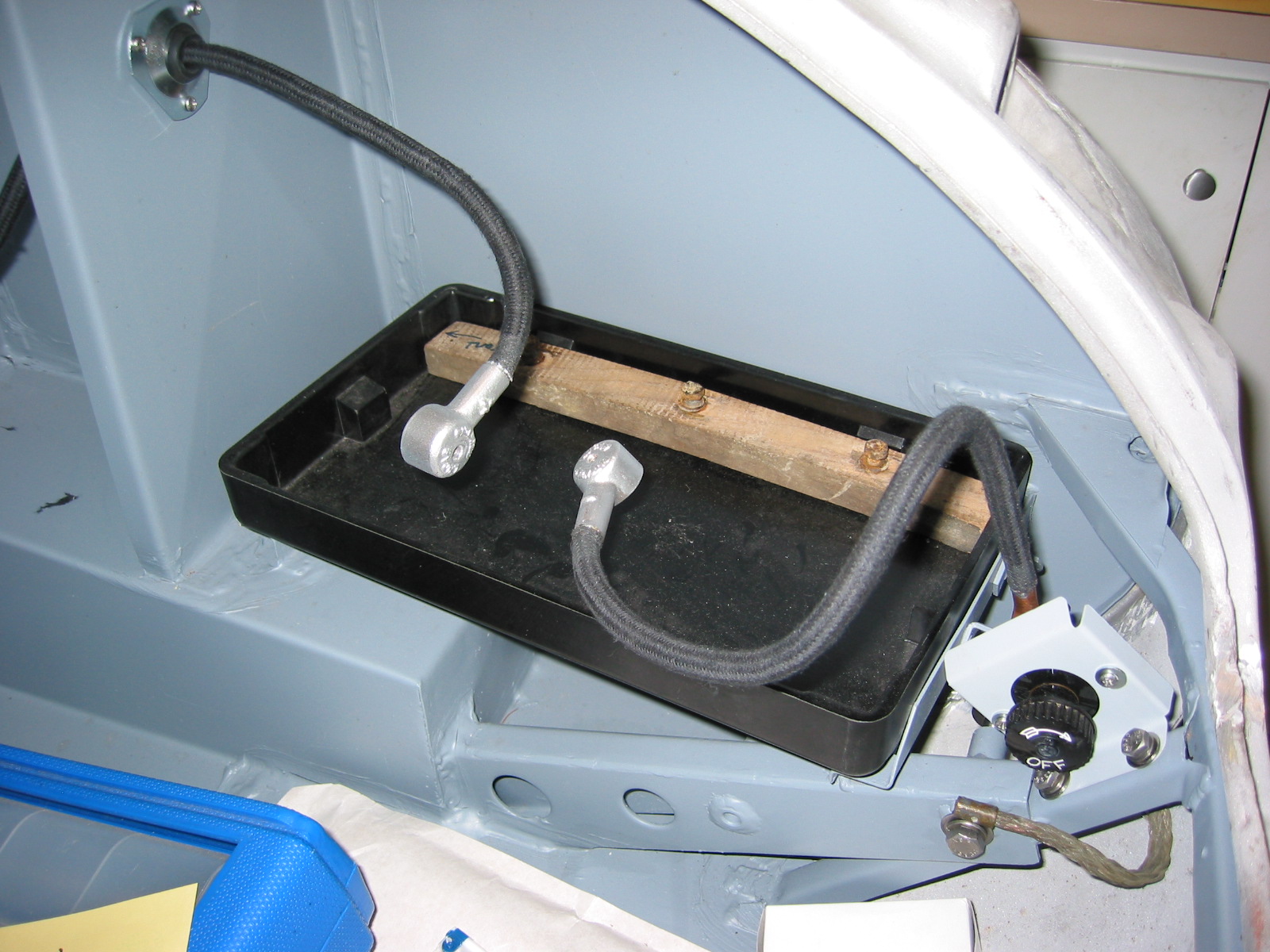
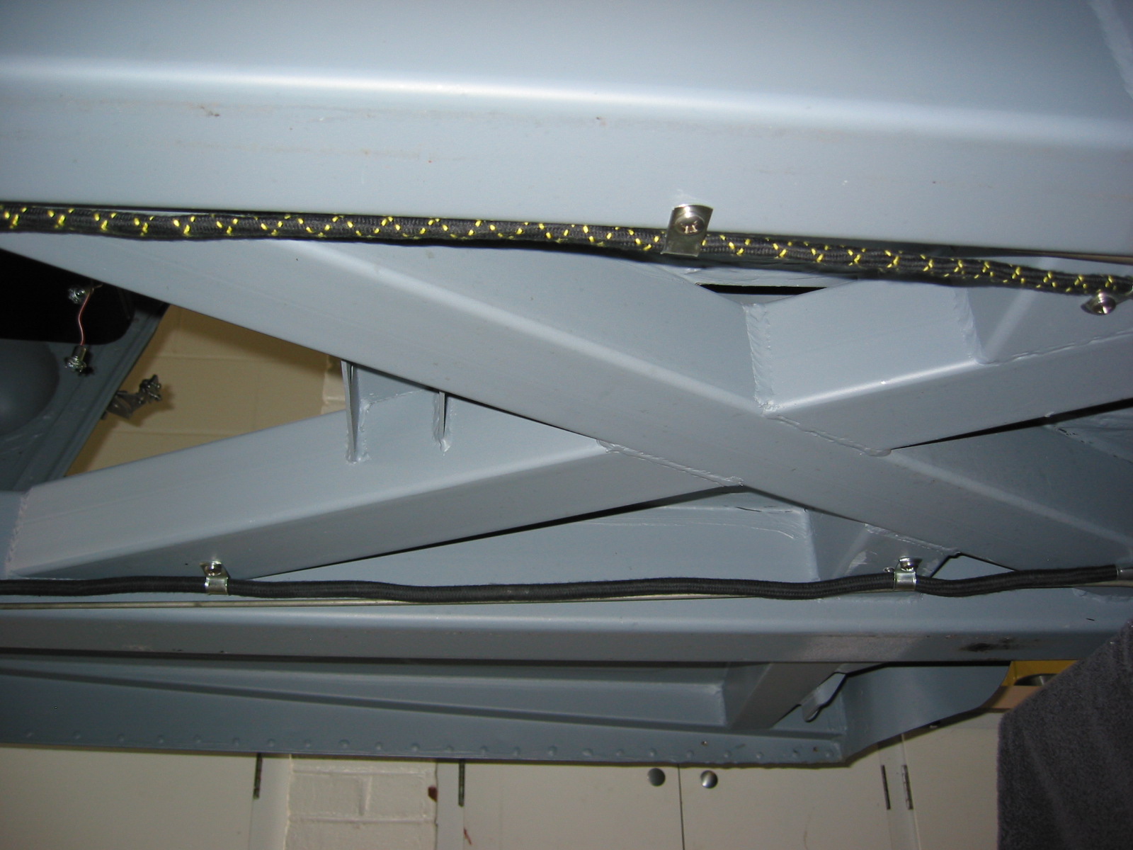
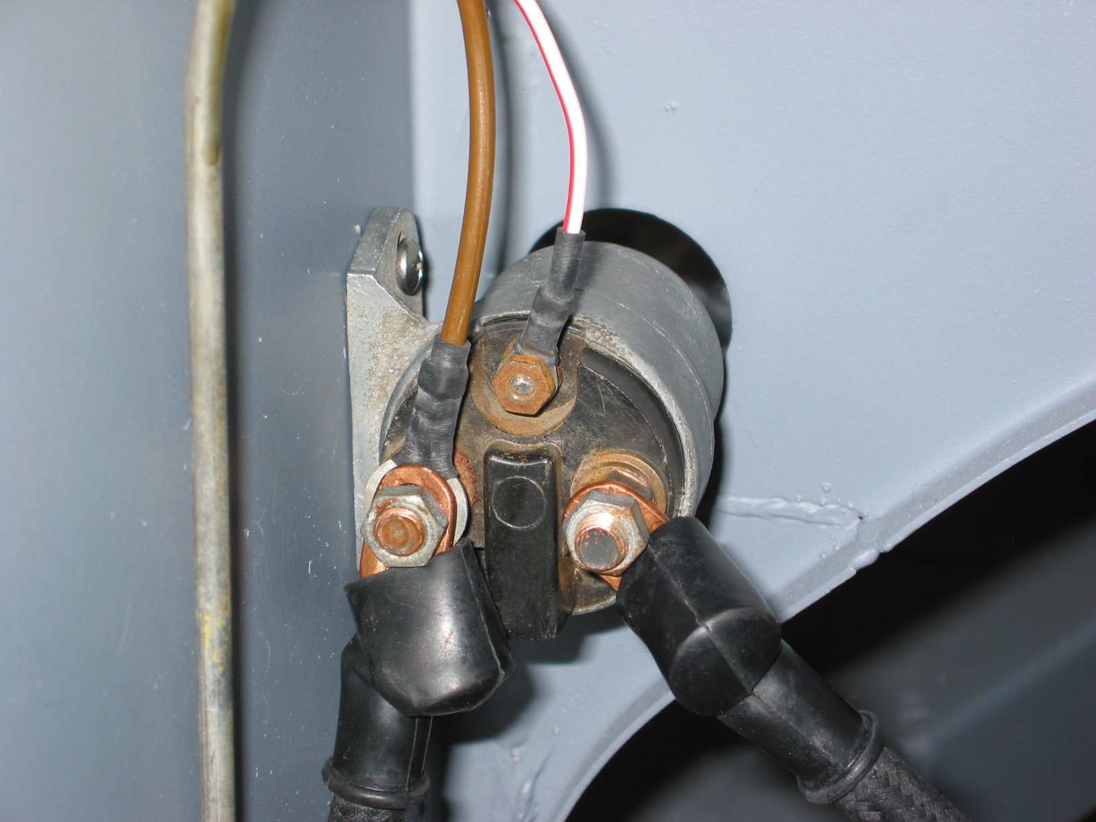
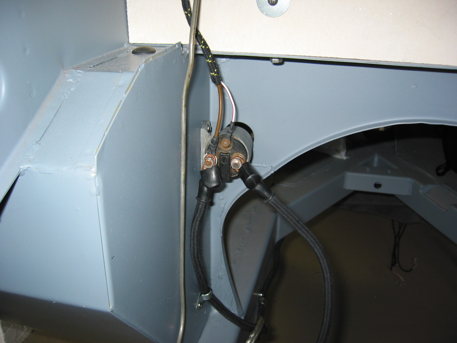
Clip 3 and clip 4 were located at the back of the cruciform. Clip 5 was located at the front of the cruciform near the gearbox mounting bracket. Clip 6 was located on the frame rail about 6” from the ground cable mounting. Clip 7 was mounted on the right footbox wall with the cable directed to the right terminal of the starter solenoid. The Cable from the starter to the left terminal on the solenoid was then secured. The white/red stripe wire fastened to the small terminal on the solenoid. Three “cert” nuts need to be installed – two for the solenoid and one for the clip on the footbox.
Battery Cable 5
Battery Cable 6
Battery Cable 8
Battery Cable 9
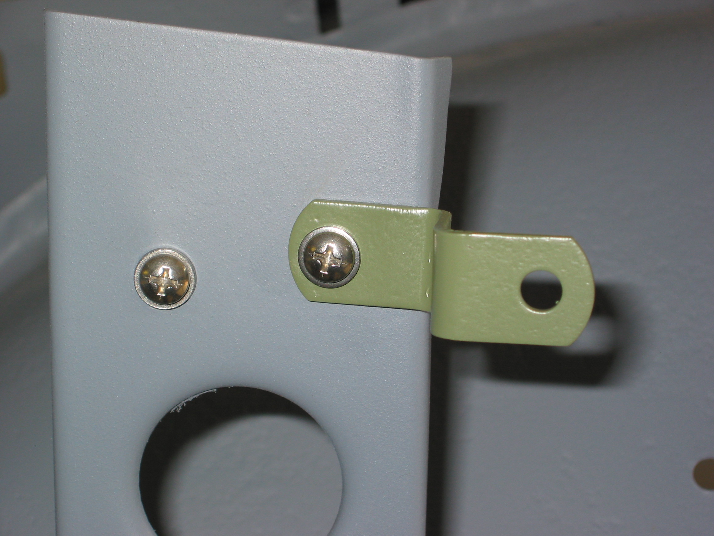
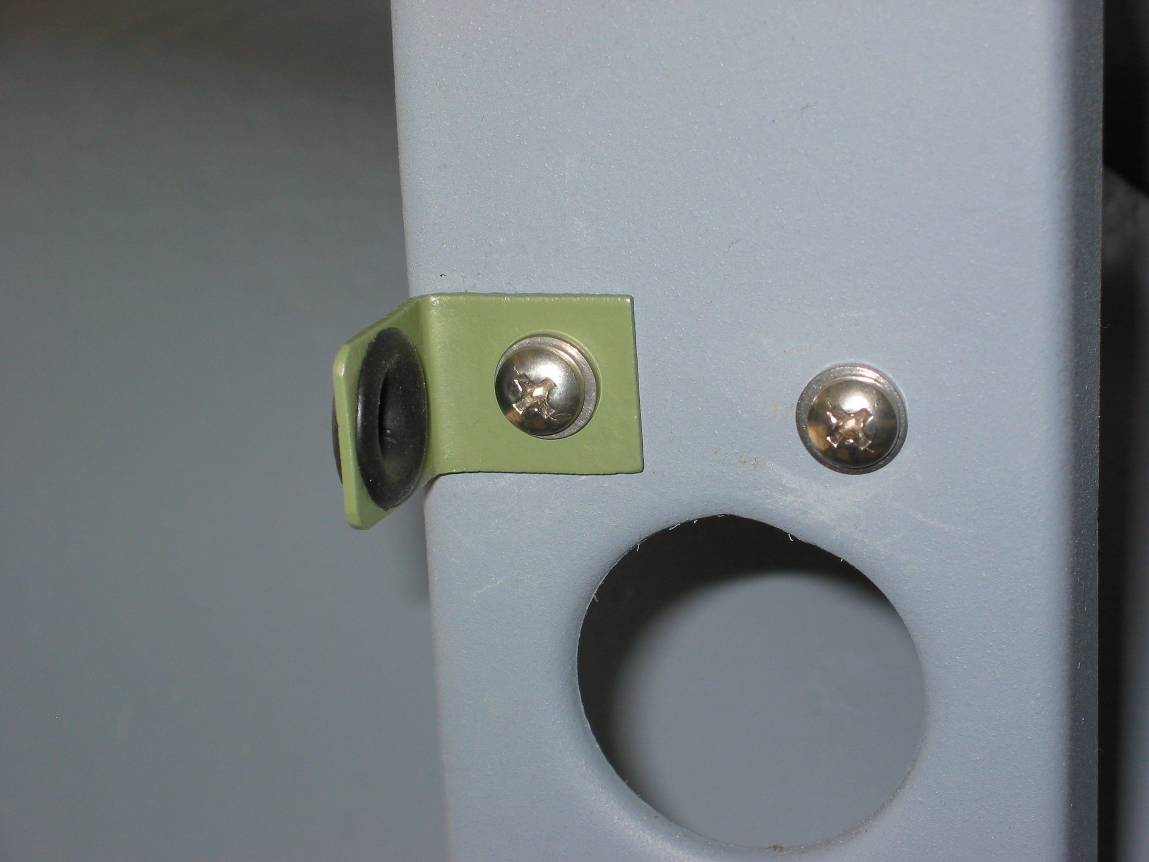
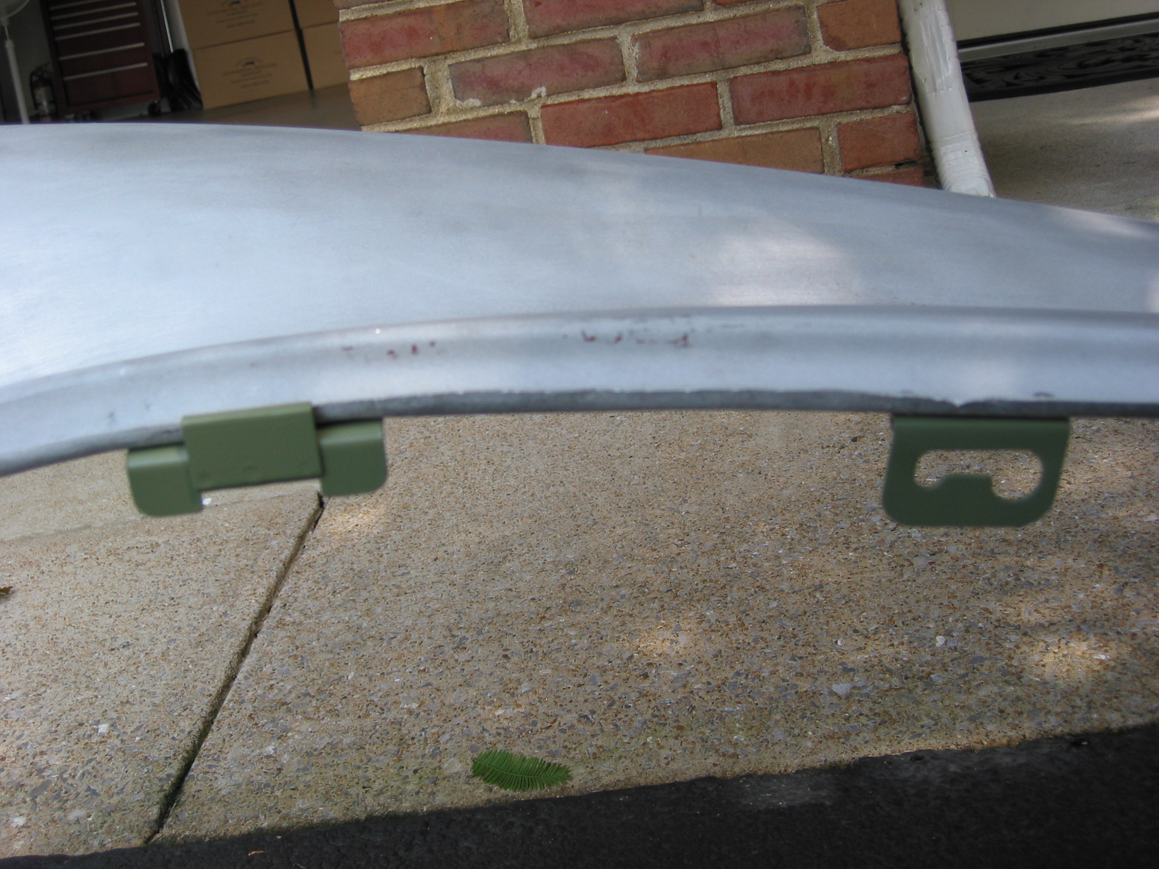
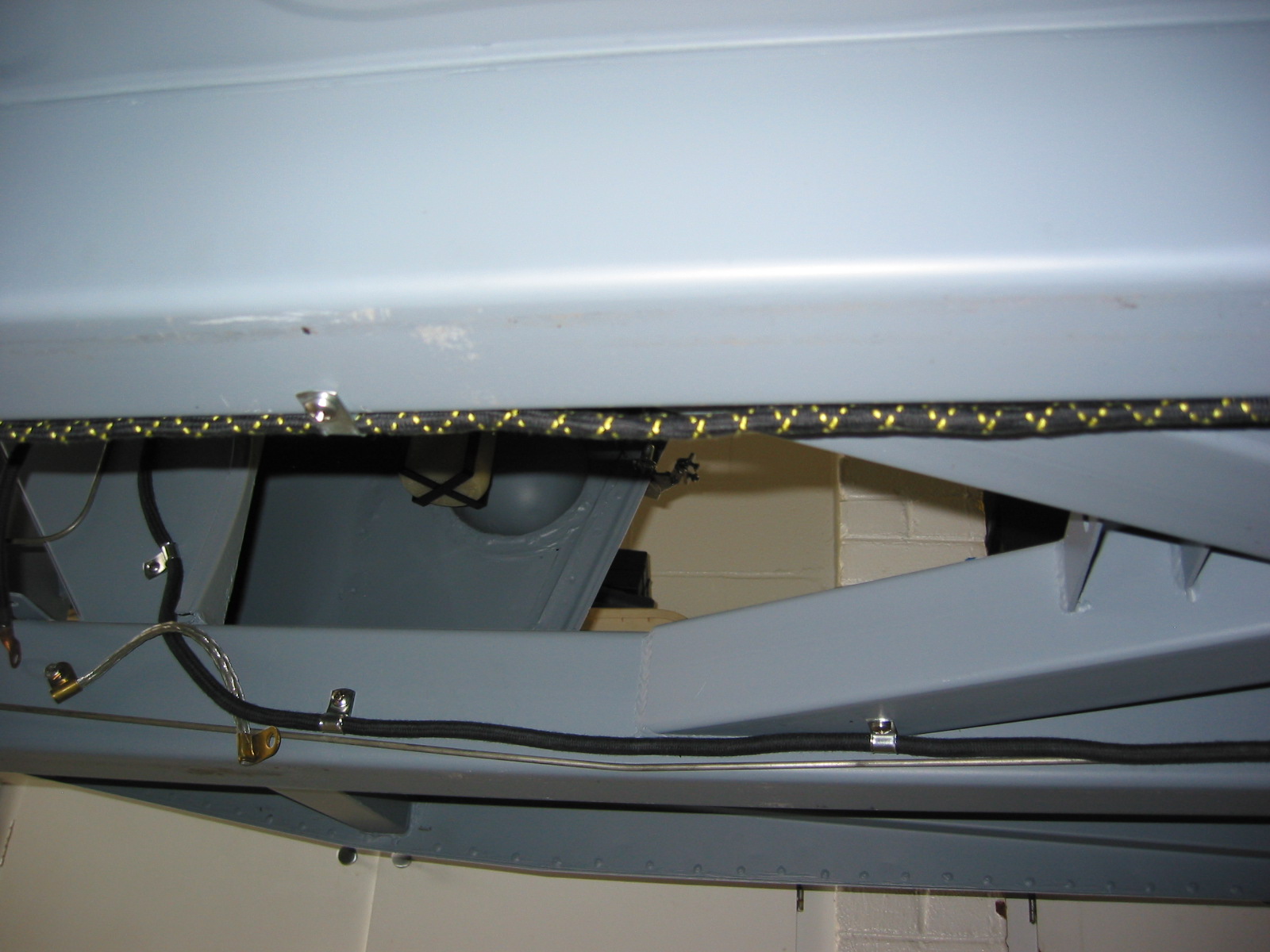
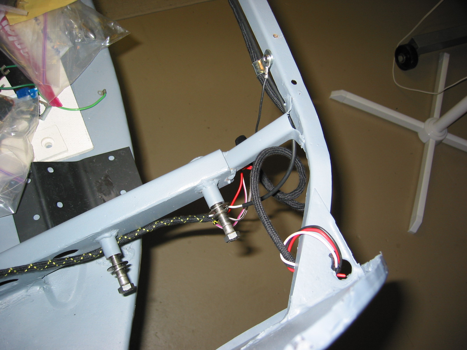
Next, the rear lights harness was installed. Clip 1 was secured at the right upper fuel pump bracket. Clip 2 was secured on the kick panel to the left of the pump. Clip 3 was attached to the left bump box and the wiring was threaded through the boot wall. The green wire will connect to the fuel gauge sending unit. Metal tabs were fabricated from clips and mounted on the floorboard of the boot.
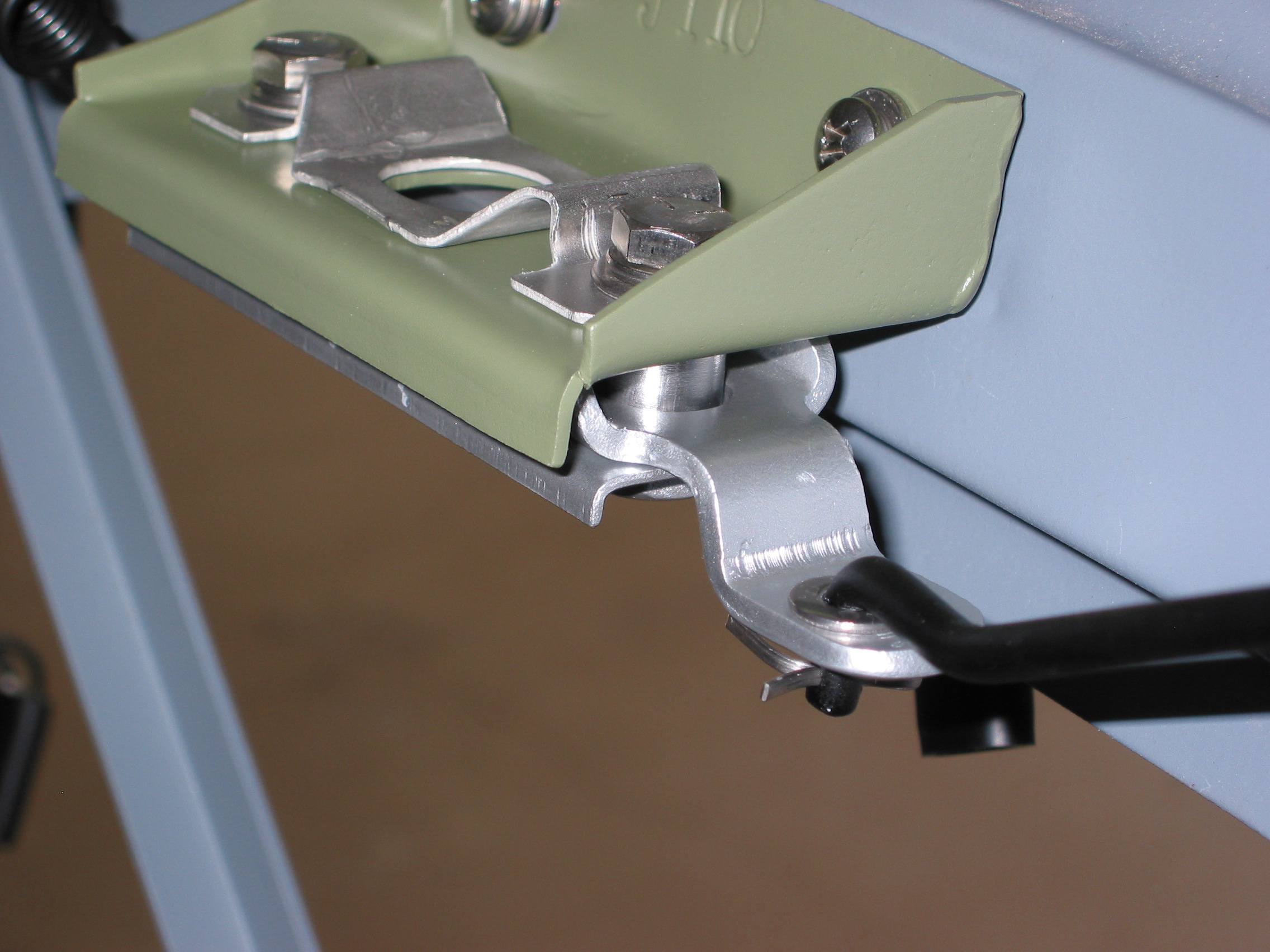
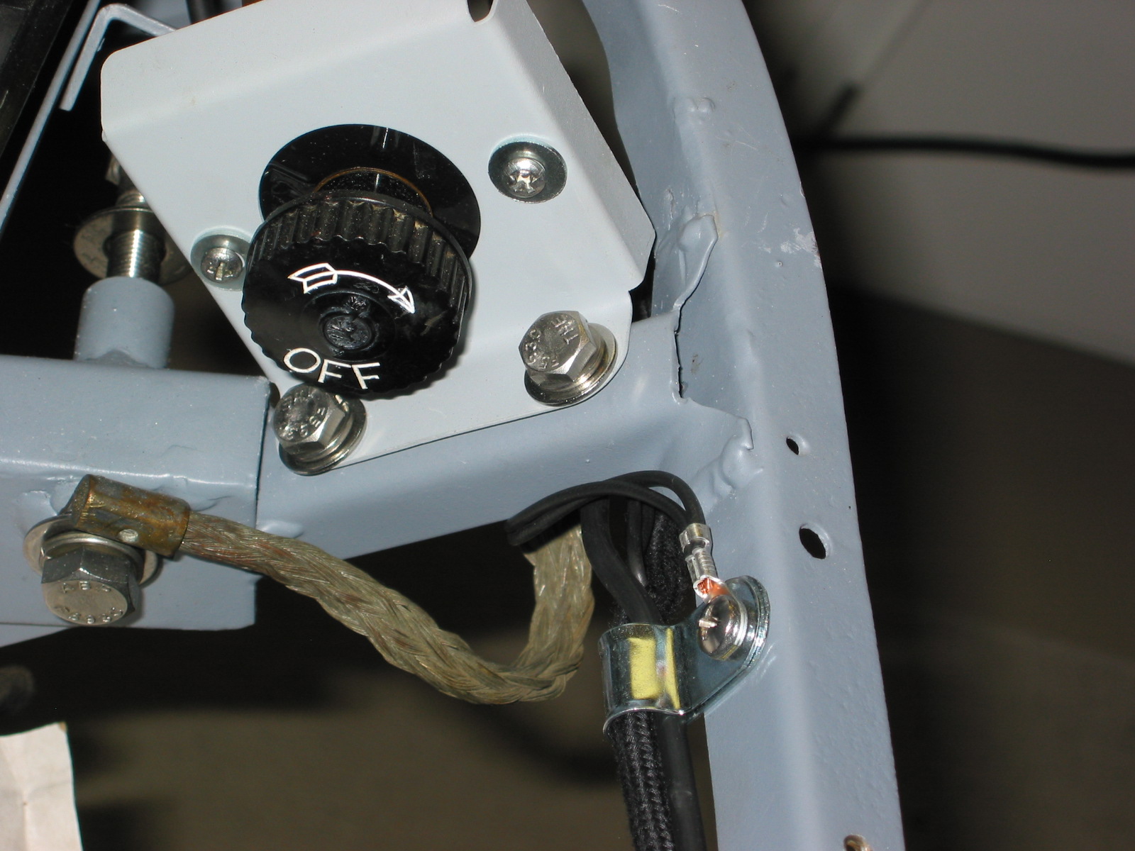
Single bullet connectors were used to join the main harness to the rear light harness and link the white/black wire, and the white/purple wire. The red wires were connected using a double rubber connector. Clips 3 and 4 were mounted to the rear rail. The long separate white/black wire was also routed through and it connected to the single screw terminal on the battery on/off switch. Black ground wires were connected to the screw on each clip.
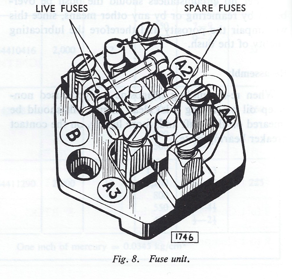
The heart of the original Jaguar MK2 electrical system was a fuse panel assembly located on the LH engine bay valance under the bonnet. The fuse panel bracket assembly houses the RB310 Voltage Control Box (Regulator), the Fuse Box unit, and the Horn Relay. It has a metal top protecting the internal components which is secured by a knurled chrome thumb screw or knob. My panel was pretty rusty but cleaned up nicely with media blasting and was then powder coated black.
Today it is hard to imagine that the fusing of the entire electrical system of the car was handled by two fuses!
Fuse Unit
I am upgrading the electrical system and will be using an alternator with an internal regulator to replace the dynamo or generator. This action will eliminate the need for the voltage control box. I will use a modern Bosch automotive relay for the horns which will eliminate the need for the original Lucas horn relay. Finally, I am upgrading from the original Model SF6 fuse unit with the two glass fuses of 35 amps and 50 amps to a modern fuse/relay panel supplied by Marc Goldblatt, owner of Classic Technologies. http://www.classic-technologies.com I will be able to utilize the base of the original fuse panel bracket assembly with Marc’s fuse/relay panel and will therefore keep the fuse connections at the same location as original to the car. Marc’s panel can be mounted horizontally or vertically and I will not make a final decision on the orientation until I have the engine in place for trial fitting.
This is a link to a short video that Marc Goldblatt made about his product.
The Classic Technologies fuse/relay panel provides for 15 fused circuits with 34 pin connectors, 7 relays including horn, ignition power, fog lights, high beams and low beams headlights, starter and accessory power and 2 flashers for the turn signals and hazard lights. I selected the optional relays for LED lights.
Classic Technologies Relay Fuse Panel
The new harness is simplified and made up of discrete runs from the fuse box to the switch or accessory. The enclosure for the fuse box is 16 gauge steel with a powder coated finish that is silk screened for easy identification of the fuses, relays and terminations. The Classic Technologies panel is only 6 3/4″ (171mm) long X 4 5/8″ (81mm) wide X 2 3/16″ (56mm) tall. The lug-less terminations into unpluggable connectors are another nice feature making the installation of the panel easy and convenient.
A poster size color schematic was provided along with a clear instruction manual to guide hobbyists like myself through the installation. Marc will provide additional support if needed.
This is the original assembly:
Bracket Assembly, Mounting Horn Realy, Fuse and Control Boxes
Although the Classic Technologies Box is more often seen mounted under the bonnet somewhere, I have elected to mount it under the dash on the RH side of the interior. This will require some modification of the fiberboard panel under the dash but that should be accomplished with little problem. My installation looks like this:
Mounting of the Classic Technologies Fuse Panel
I will still use the base of the original fuse panel bracket assembly in its original location on the LH valance in the engine bay. Three Barrier terminal blocks used to make connections for lights, horns and etc., will be mounted on the LH valance and the base of the fuse bracket will be used to cover and protect the terminal blocks and wiring. On the top of the base I will be mounting fuses and connectors associated with the alternator, and power steering. I will then fabricate a new cover for the base that will shield the entire base not just 2/3 of it as was done originally. This is the powder coated mounting bracket assembly:
Powder Coated Fuse Panel Bracket Assembly
Fuse/Relay Panel Design Theory
The 15 fuses are broken up into three groups:
1. Constant Power: Fuses F1 through F4, F8, and F15. These fuses are tied to the battery + terminal (B+). Examples: Dome Lights, Parking Lights, Hazard Flashers, and Horn. These features have power regardless of ignition switch position.
2. Ignition Power: Fuses F5, F6, and F7. These are items that are critical to starting the car that should have power while the car is being started. Examples: Coil, Alternator excitation, Fuel Pump, Gauges/Warning Lights, brake lights.
3. Accessory Power: Fuses F 9 through F14. These are items that are not critical to starting the car and should not have power while starting the car to maximize power to the starter. Additionally, in order to prevent battery drain, these items should not have power when the keys are removed from the ignition. Examples: wipers, heater motor, turn signals, overdrive, radiator fan, radio, reverse lights…
New Wiring System Requirements
In addition to the gauges, switches, and components typical of the MK2 that the Classic Technologies Fuse/Relay Panel would manage, the modifications to my car will necessitate individualizing the wiring schematic that Marc provides with his panel kit.
I will need to add circuitry for the following features:
Air Conditioning
My car was not air conditioned originally. I am installing an after-market kit produced and sold by Rock Browning of RetroAir, Inc. As I see it, the kit has the following electrical components that will need to be incorporated into the new wiring diagram.
SPAL 12” Electric Radiator Fan – 5.3 amps
Water temp sender to cut fan on/off Circuit breaker
Fan relay
Trinary switch
Compressor relay
SPAL 3 speed Blower Fan to circulate air – 16 amps max
Control panel switches – 3 speed fan switch, temperature switch
Power Steering Pump
My car did not have power steering originally although it was an option at the time. I have installed rack and pinion from a later Jaguar that uses an electric power steering pump. The vendor, M&C Wilkinson reported “The power steering pump uses approximately 40 amps at maximum draw which is slow speed/full lock.”The vendor also supplied an 80 amp fuse and a connector block.
Upgraded Wiper System
I am using a more recent Jaguar wiper motor and a modified wiper switch all purchased from Classic Motor Cars in England. I understand the amperage requirement to be 6 amps.
Power Front Seats
I am using seats from a later Jaguar (1990 Daimler XJ40). Although the seats have heaters, memory and a few other gadgets such as a seat belt alarm, I intend to only use the seat motion adjustments (four switches for each seat that will be mounted on the central console), and the lamps on the rear of the front seat headrests. The back of the seats have folding “picnic” tables.
Looks like the seats require 5 amps (7.5 max) each. Each seat needs a relay.
Sound System Amplification
Specifications for the amplifier have yet to be determined, but I anticipate perhaps a 300 watt amplifier requiring approximately 25 amps.
Accessory Power Outlets
Redundant Fuel Pump
Third Brake Light
Back-up Camera
Headlight Warning Chime
British Wiring Codes
I plan to stick with British Wiring Codes wherever possible in the rewiring of the MK2.
Mike McPhail, the president of the South Texas Austin-Healey Club, published an article in the July, 2010 issue of Regional Rumblings, the Club’s newsletter that provided an excellent color coded summary of Lucas wiring that will surely prove helpful with the Jaguar as well.