
Relay/Fuse Panel Location
As I have already indicated, my wiring harness design is very similar to Eric’s and I give him all the credit for thinking through the logic of the approach. However, we do differ in some respects.
I decided to mount my Classic Technologies Relay/Fuse Panel below the right side of the dash fascia, in front of the RH passenger seat. While in this photo it appears that its location would be obtrusive, it really is not.

Mounting of the Classic Technologies Fuse Panel
This will require the modification of the finish panel below the dash, but then that was going to have to happen anyway to accommodate the blower and vent for the air conditioning. Moving the relay/fuse panel to this location also eliminated a significant amount of wire from the engine bay.
As will be described below, the interior placement of the fuse panel also allowed me to use the original Jaguar fuse panel mounting assembly as a screen for three barrier blocks used in the engine bay for the high beams, low beams, horns, fog rangers, side lights, and ground connections.
Wiring Connections
As has been stated previously, I am “building up” this car to the point of being able to test the electrical system, drive train, air-conditioning, power assisted rack and pinion, upgraded brakes, motor, gearbox, overdrive and etc. I will then “take it down” again for paint, and then have a final reinstall of all components. I would not do this if I was truly restoring the car, but this is a mild rest-mod and I simply feel better testing everything in advance of paint.
Although it could well be properly classified as anal, I prepared a spreadsheet of basically every electrical connection in the car. I did this to use in conjunction with wiring diagrams. The diagrams alone just don’t give enough information about wire routing that the spreadsheet affords. The spreadsheet is still a work in progress. It needs some “cleaning” and I am sure I missed a few things, but I will modify as I go and will revise the spreadsheet as changes are made. I anticipate that this spreadsheet will be helpful when I reinstall the wiring in the car after paint.
Again, a disclaimer is appropriate: The spreadsheet is provided as guidance for those who might wish to do something similar, but it should not be duplicated or utilized without careful inspection and approval by a certified automotive electrician.
This alphabetical listing of components is provided to help quickly identify items in the electrical system. A spreadsheet line number(s) associated with the component is indicated.
Rose Jaguar MK2 Electrical Connections Alpha listing
This is the spreadsheet showing all connections:
Rose Jaguar MK2 Wiring Spreadsheet Modified 6-14-17
The Central Gauge/Instrument Panel
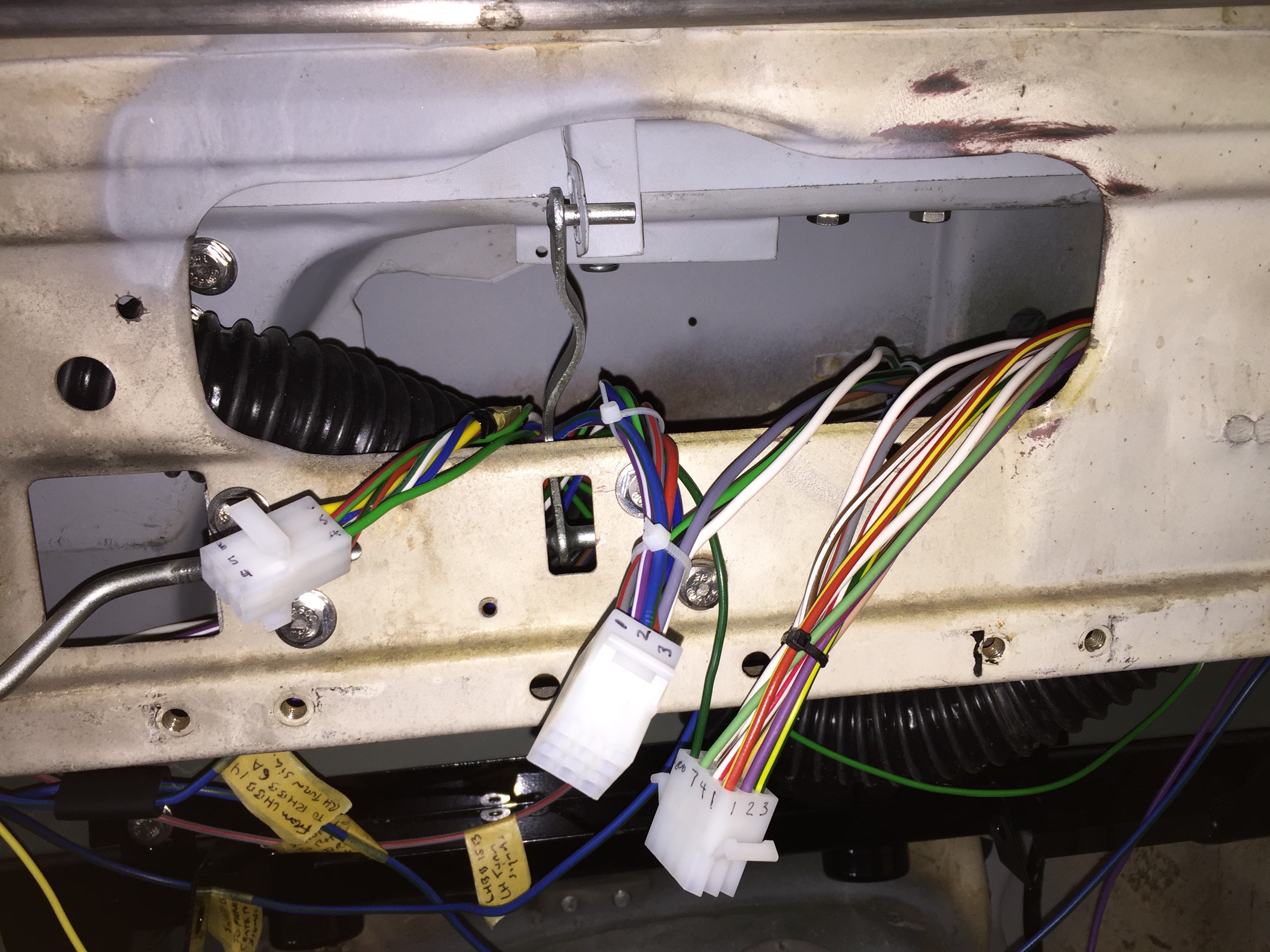
The instruments/gauges and switches included in the Instrument Panel Assembly are detailed in the post “Gauges, Instruments and Switches.” I wanted to make the panel truly modular so many of the wires emanating from the gauges and switches on the instrument panel assembly are routed through three Molex connectors. It is now possible to disconnect the three connectors and remove the Instrument Panel Assembly from the car. The wires associated with each of the Molex connectors are routed through a bracket with a large rubber grommet. From that point wires travel either through one of the ports on the firewall or to one of the barrier block terminals under the dash.
Two twelve station Molex connectors and one six station connector are utilized in my wiring plan.
Of course, the tape will disappear later and the wiring will have a little housecleaning.
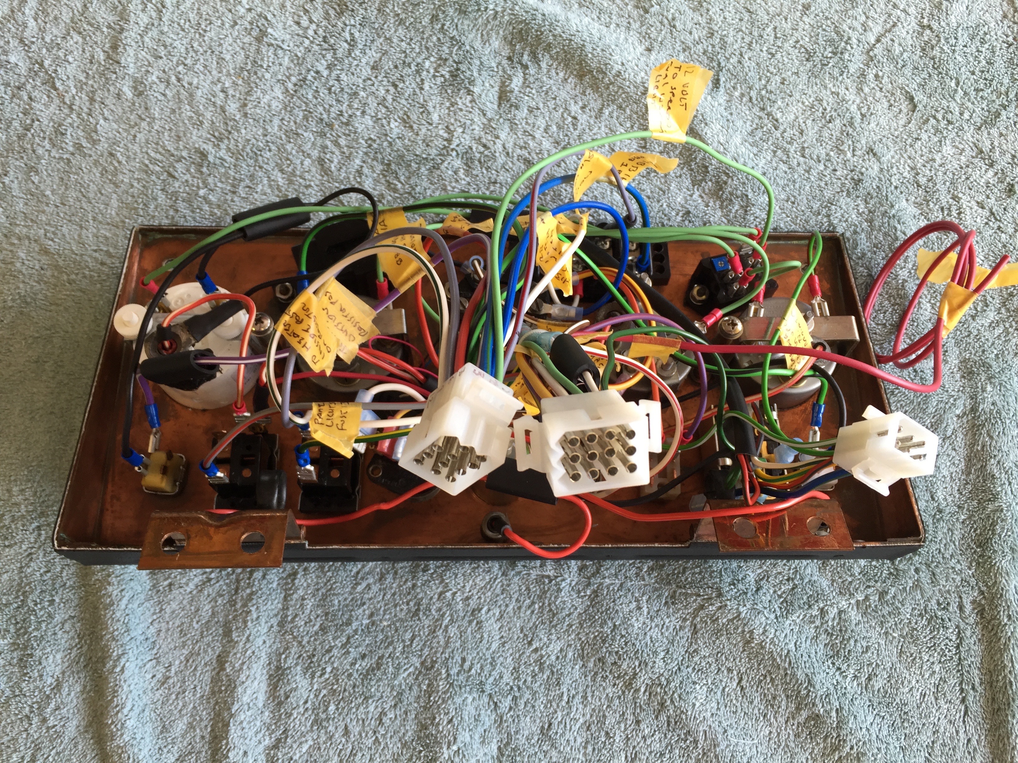
Gauge Panel with Molex Connectors
Molex Connectors for Central Gauge Panel Assembly
I refer to these Molex Connectors as “A,” “B,” and C.” The individual wiring connections are shown below:
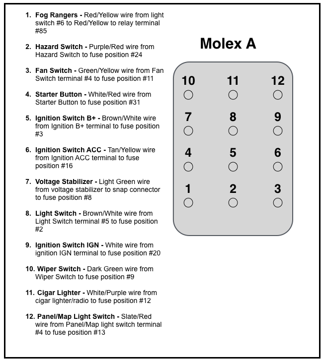
Rose Jaguar MK2 Molex A Connections
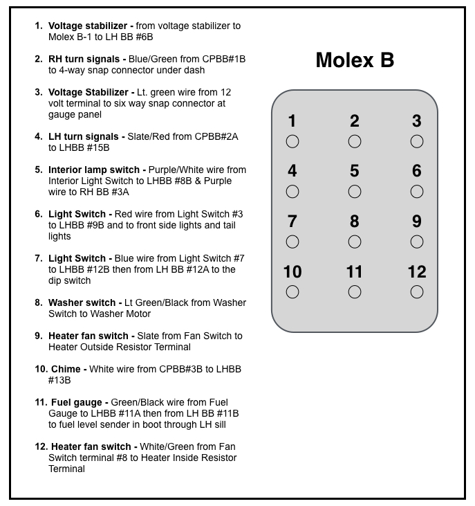
Rose Jaguar MK2 Molex B Connections
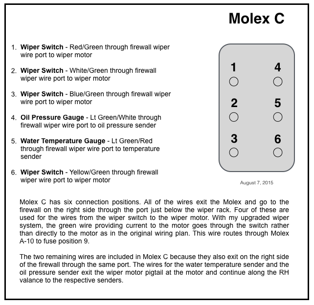
Rose Jaguar MK2 Molex C Connections
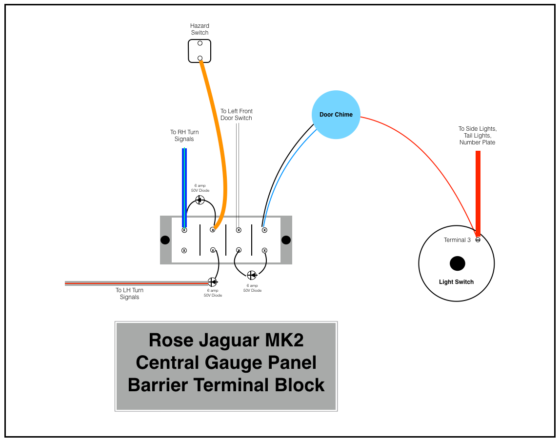
As suggested by Eric, I also used one small barrier terminal block behind the central gauge panel. This is used to accommodate our new hazard flasher system and the alarm chime to remind the driver upon exiting the car that the headlights are still on. The image below shows the eight position terminal block as originally conceived.
Jon Langley, a fellow restorer who has also elected to design his own electrical system for his MK2, pointed out that with this configuration opening any of the four doors would sound the alarm chime. So,…
Rose Jaguar MK2 Central Gauge Panel Barrier Terminal Block
He recommended the use of a twelve position terminal block and with this modification only the driver’s door will activate the chime.

Rose Jaguar MK2 Central Gauge Panel Barrier Terminal Block – Modified
Wiring Distribution throughout the Car
As I have already mentioned, I used barrier terminal blocks as connection points for the wiring distributed throughout the car. The LH blocks are located below and behind the steering column and the RH block is located to the right of the Classic Technologies Relay/Fuse Panel below the Cubby Box. This diagram illustrates the connection points and routes for the LH and RH terminal blocks. Clicking the image twice will make the diagram more readable!
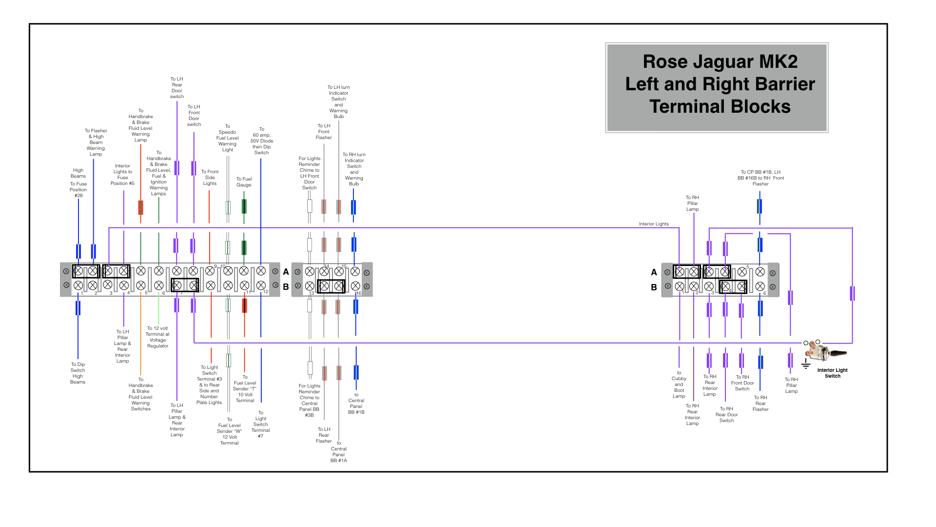
Rose Jaguar MK2 Left and Right Barrier Terminal Blocks
There are three 4-gang barrier blocks mounted in the engine bay on the left hand valance under the original fuse panel. Each of the blocks have clear plastic covers. They provide connection points for the headlights, with low and high beam; the Fogranger fog lamps, the horns and the side lights. The image below provides a wiring diagram:
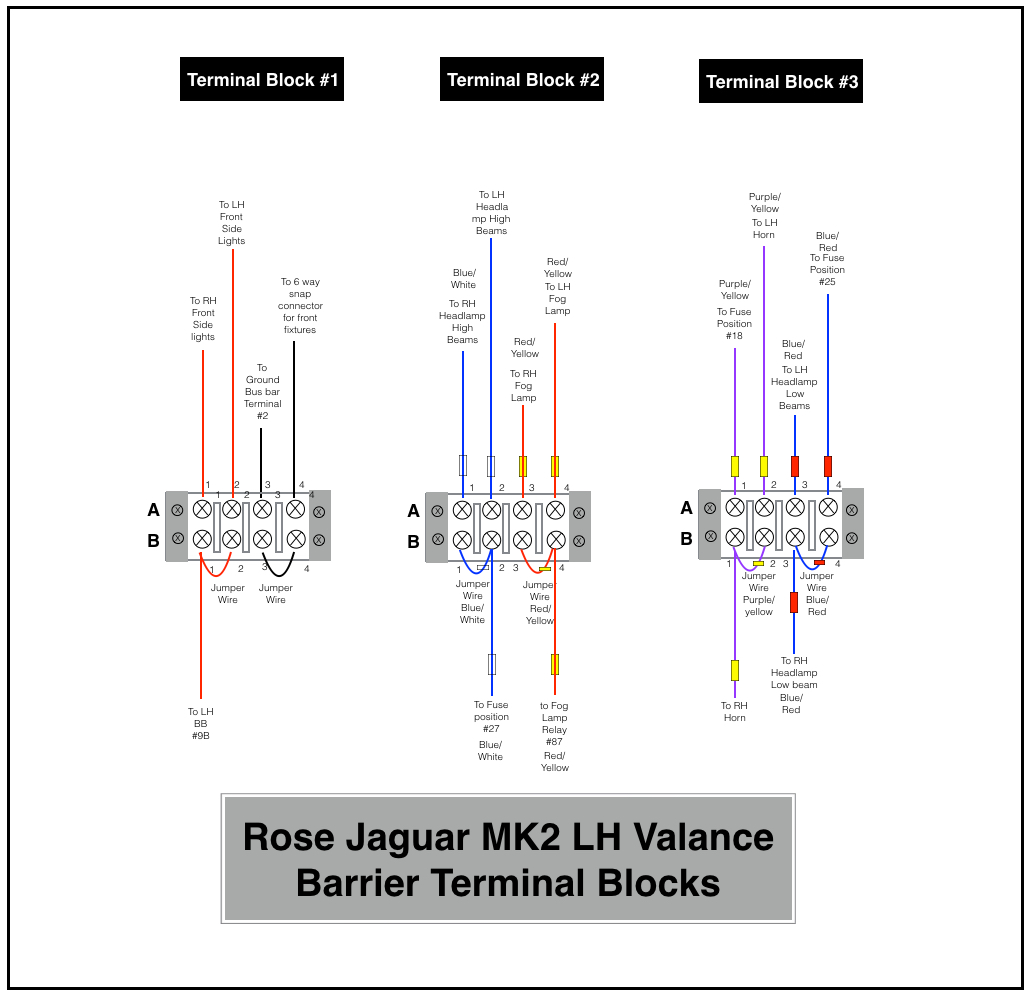
LH Valance Barrier Terminal Blocks
In addition, the photo below shows the three blocks installed.
Things may look a bit chaotic, but the three blocks are arranged the way they are so that they could be covered by the original fuse panel.
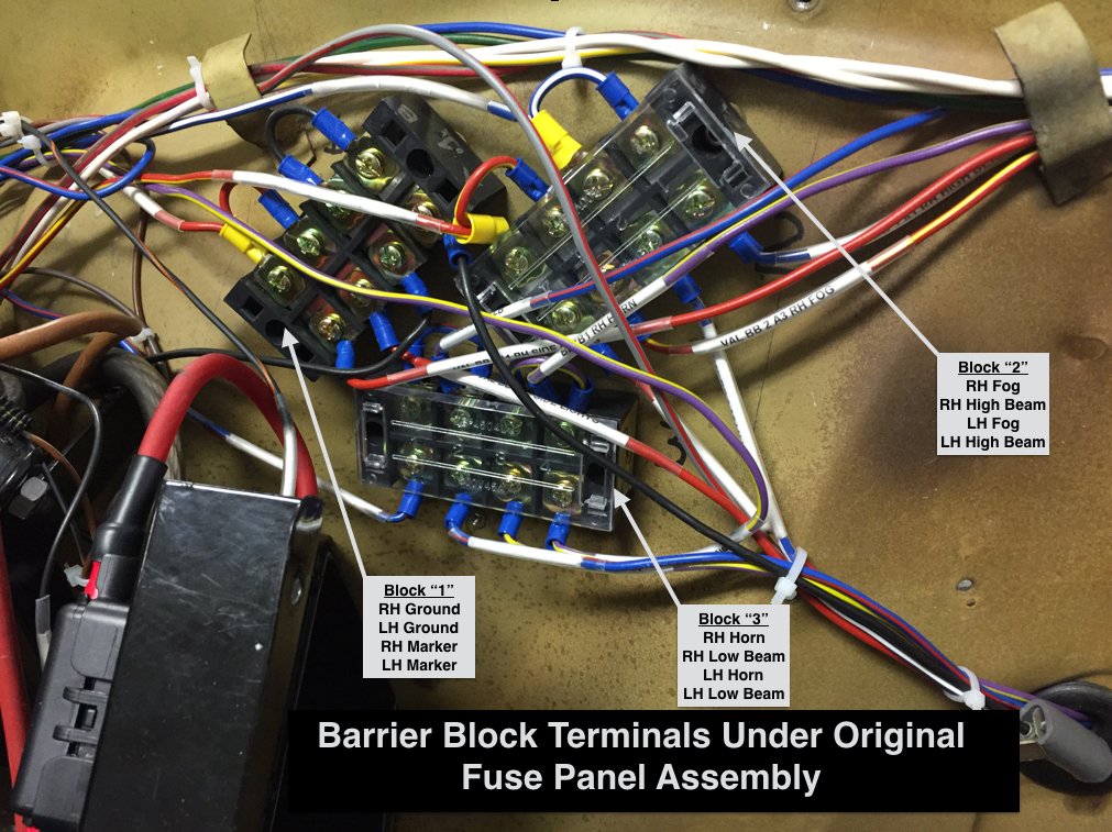
Barrier Block Terminals Under Original Fuse Panel Assembly
Of course, in my final harness the zip ties won’t be there and the wiring will be covered!
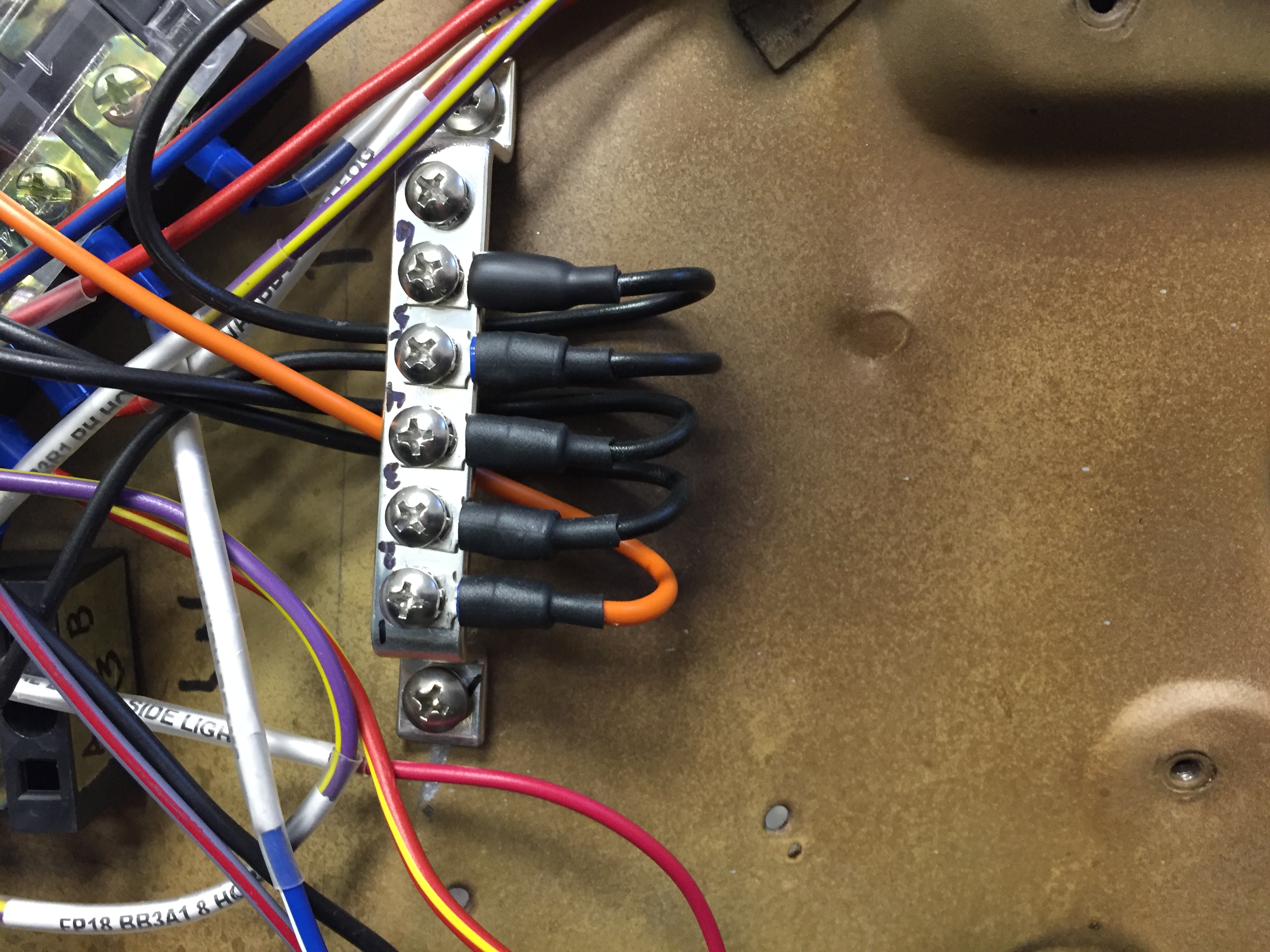
Grounding Bus Bar
To try to bring some order to the ground connections required by various components in the electrical system, I used bus bars with six terminal mounts in four locations throughout the car. There is one bus bar on both the LH and RH engine bay valance as well as one under the steering column and one under the console on the transmission/propshaft tunnel. These eliminated the need for individual ground connections scattered about the car.
This will provide for much easier tracking of ground connections.
Ground Bus Bar