Body Fittings
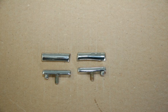
Finishers on “A” Posts
The original finishers were in excellent condition. I had both rechromed for the project. Though two of the tabs have holes in them as if for screws, no screws are used for installation. The tabs are tightly bent over the posts and the finishers are glued to the post.
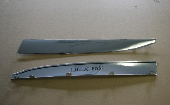
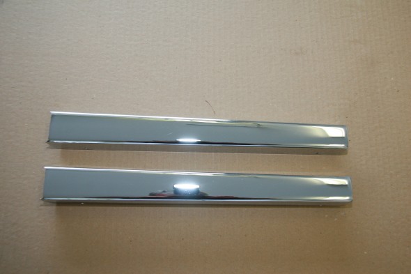
Finishers on “A” Post New Chrome
Finishers on the Center “B” Posts
These finishers were also in very good condition and were rechromed for use in the restoration.
Finishers for B/C Posts New Chrome
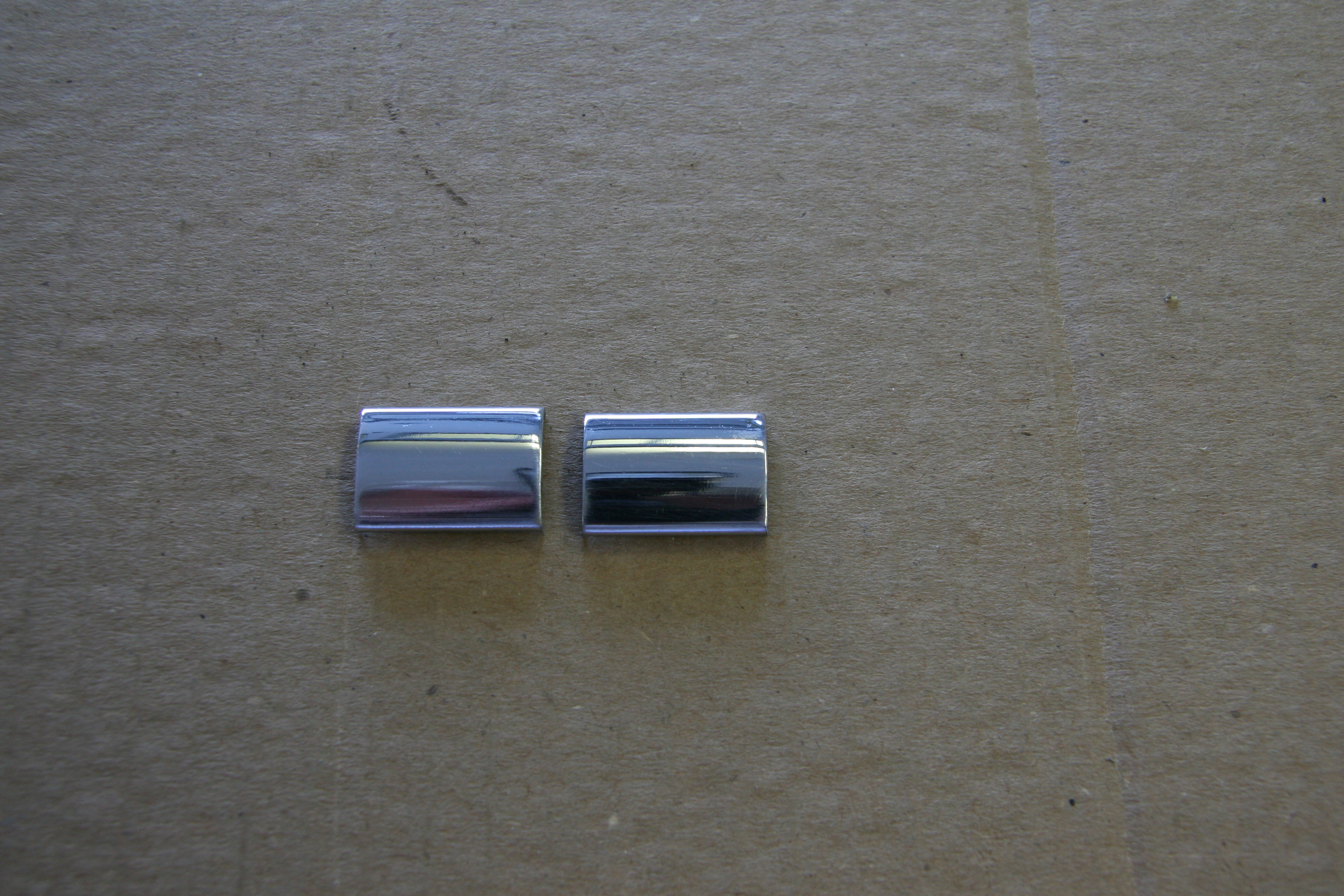
Chrome Bead Upper and Lower for B/C Posts
I had these little pieces of Bead rechromed for installation on the car.
Chrome Bead for Upper and Lower for B/C Posts
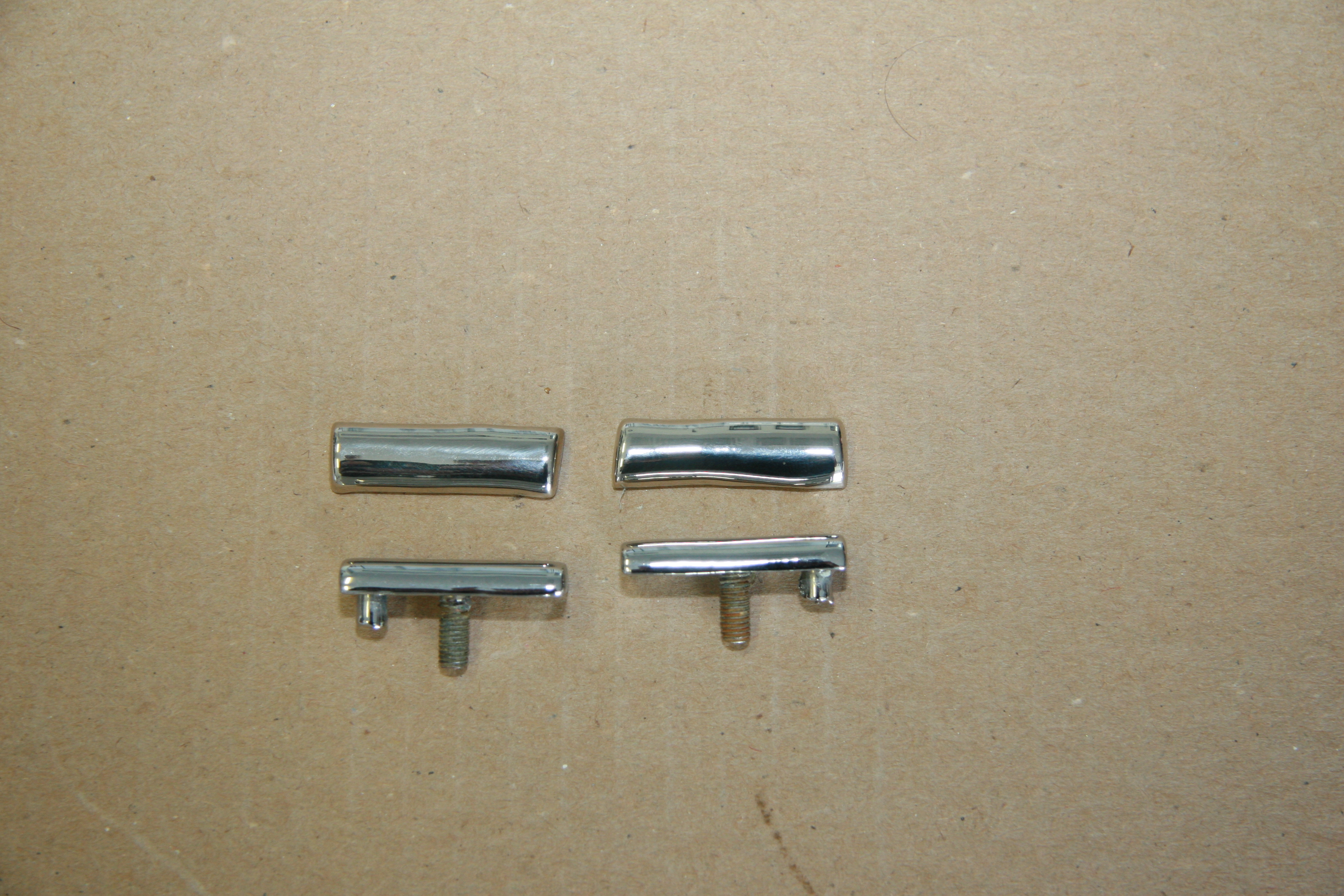
Joint Piece at Centre of Drip Moulding Finishers
These two little pieces were in good shape so I simply cleaned and polished them. They are held in place by two chrome #4 flat head 1/4″ self tapping screws.
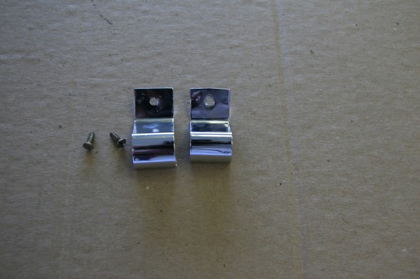
Joint Piece at Centre of Drip Moulding Finishers
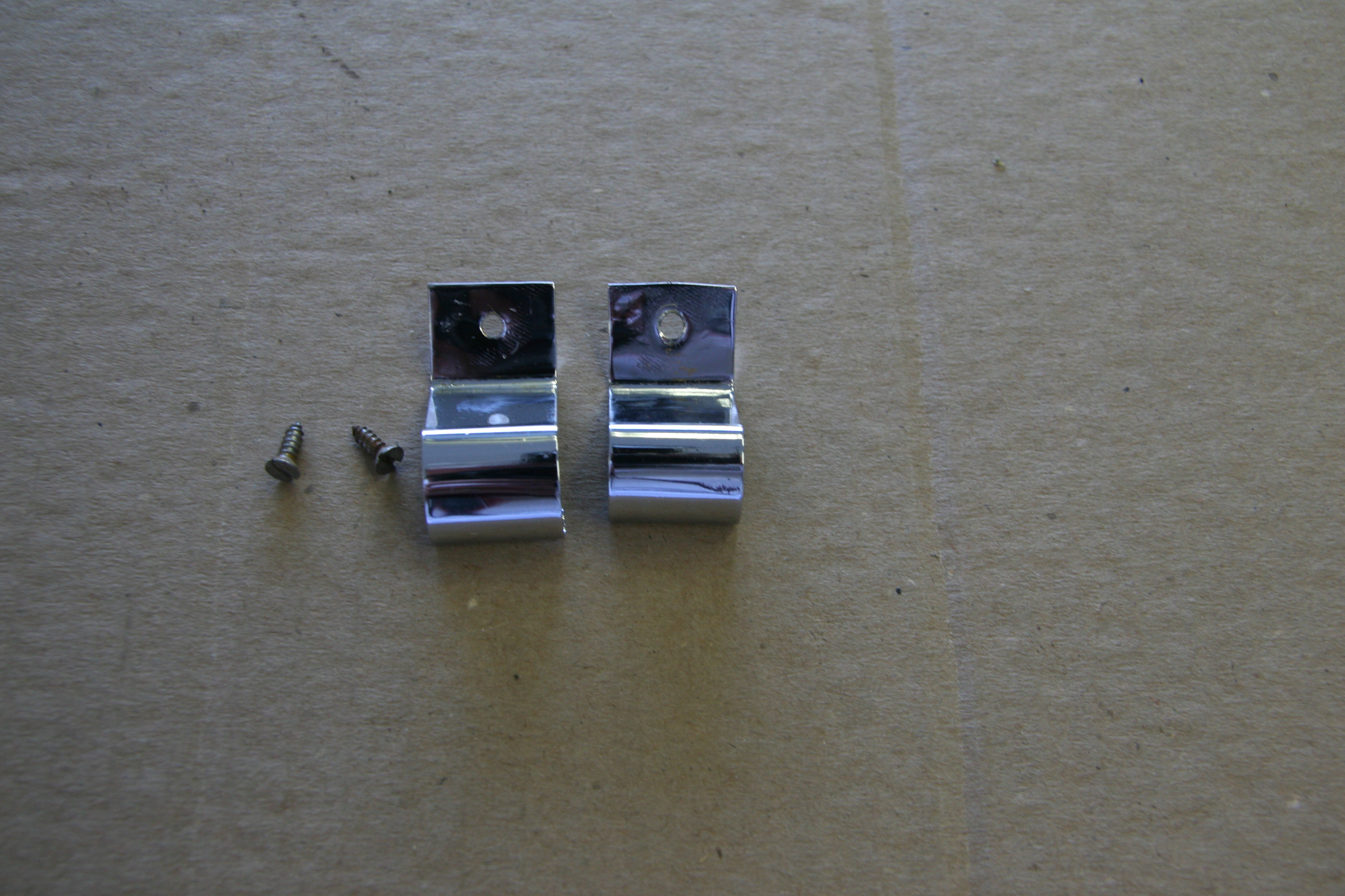
Joint Piece for Chromium Finisher Around Backlight Glass
These were also in good condition so I cleaned and polished them for future use. A silicone adhesive was used to hold these in place.
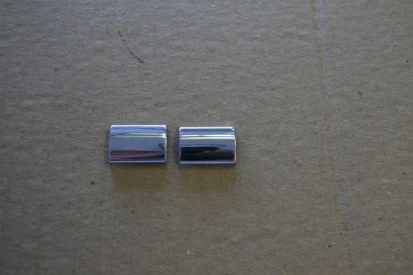
Joint Piece for Chromium Finisher Around BackLight Glass
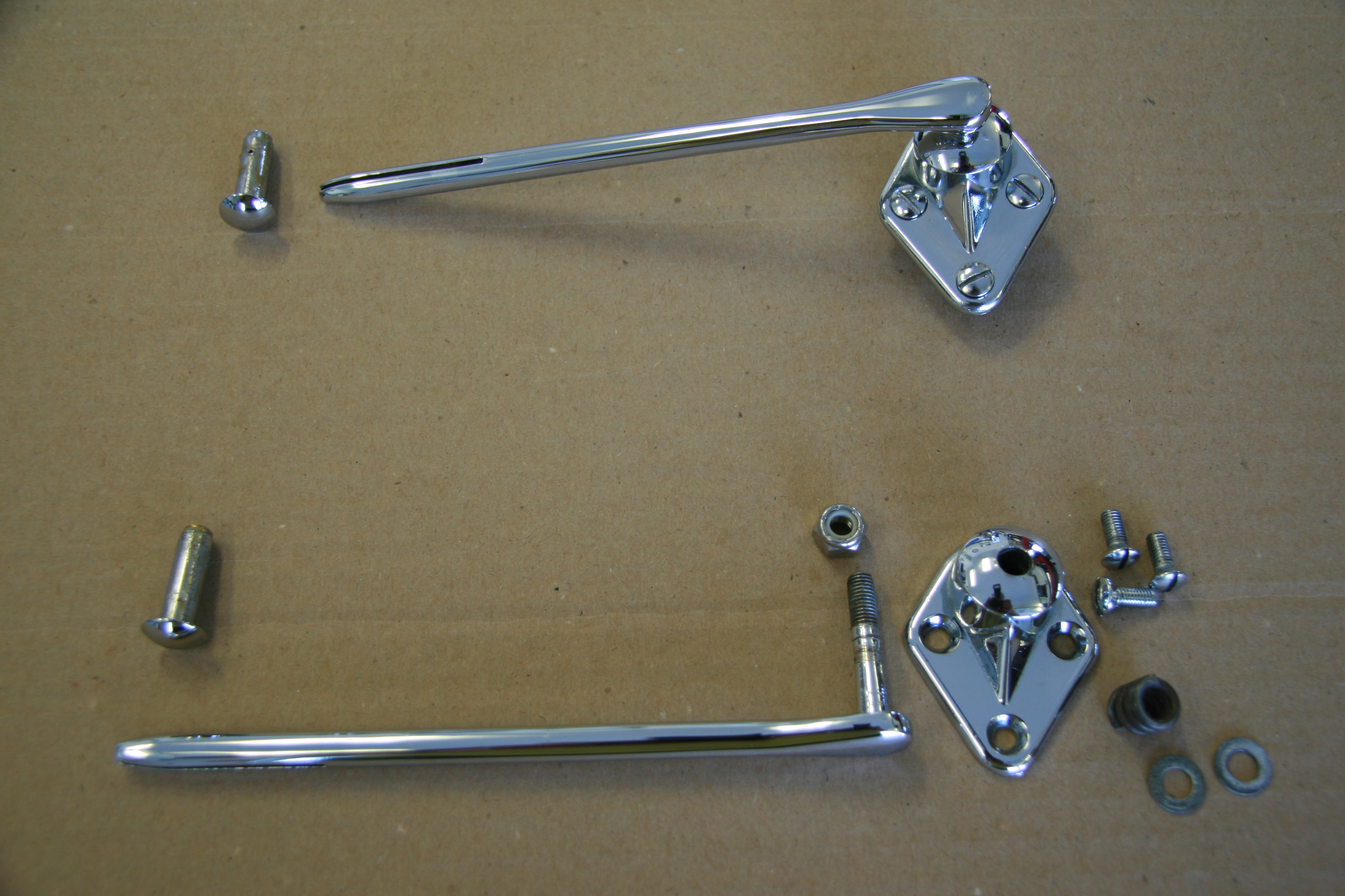
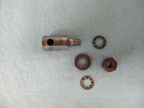
Interior Mirror Assembly on Windscreen Header Panel
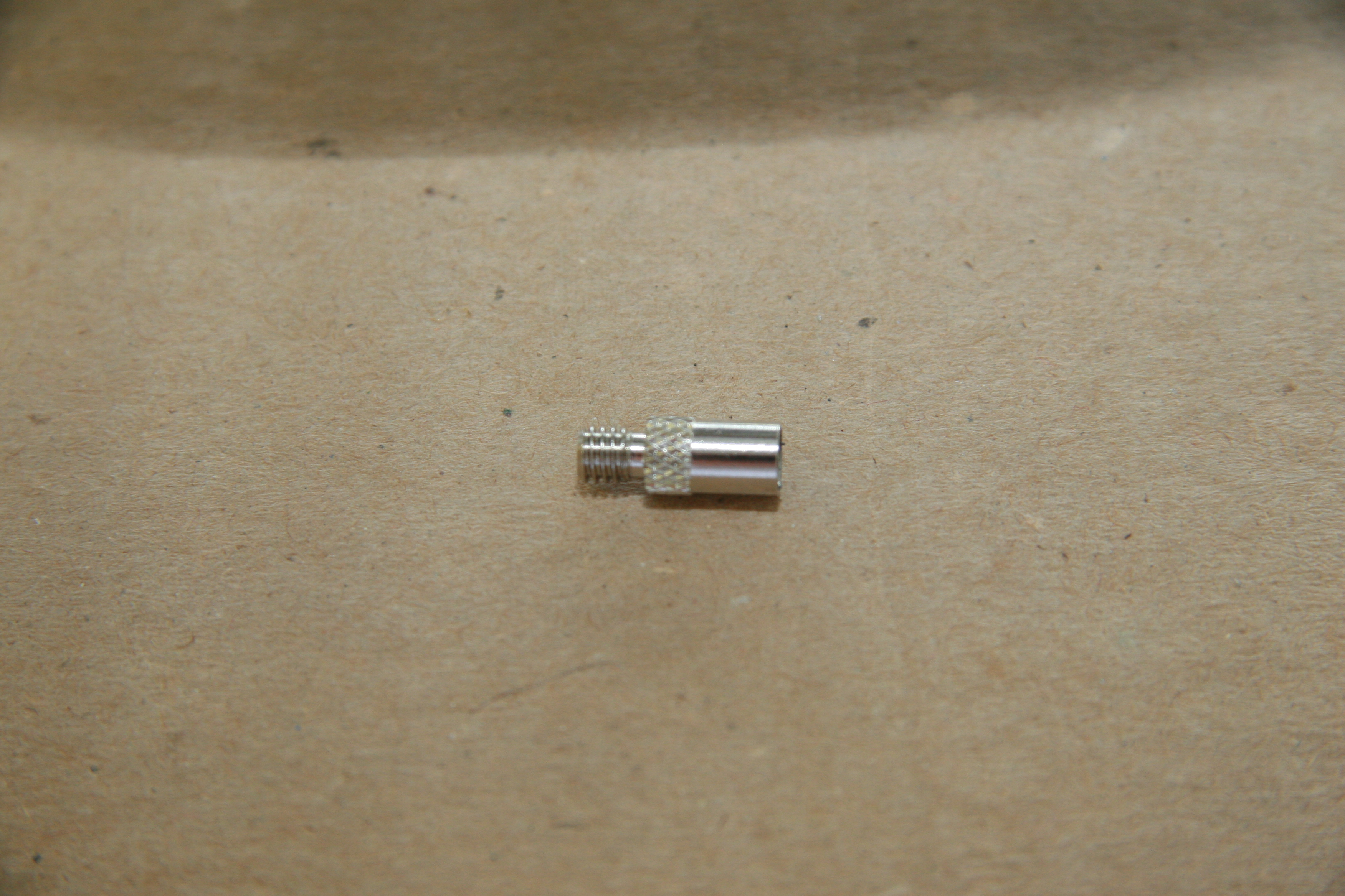
While the rearview mirror appears to be in good enough condition to restore rather than replace, I did have to purchase a new mounting bracket and locking nut. The threads on the originals were completely stripped. I had the post rechromed and whether as a result of the rechroming or the new bracket and nut having slightly different dimensions, the post would not slide in the bracket. I very carefully drilled out the nut and bracket with a 9/32″ drill bit and the post now slides and locks as it should.
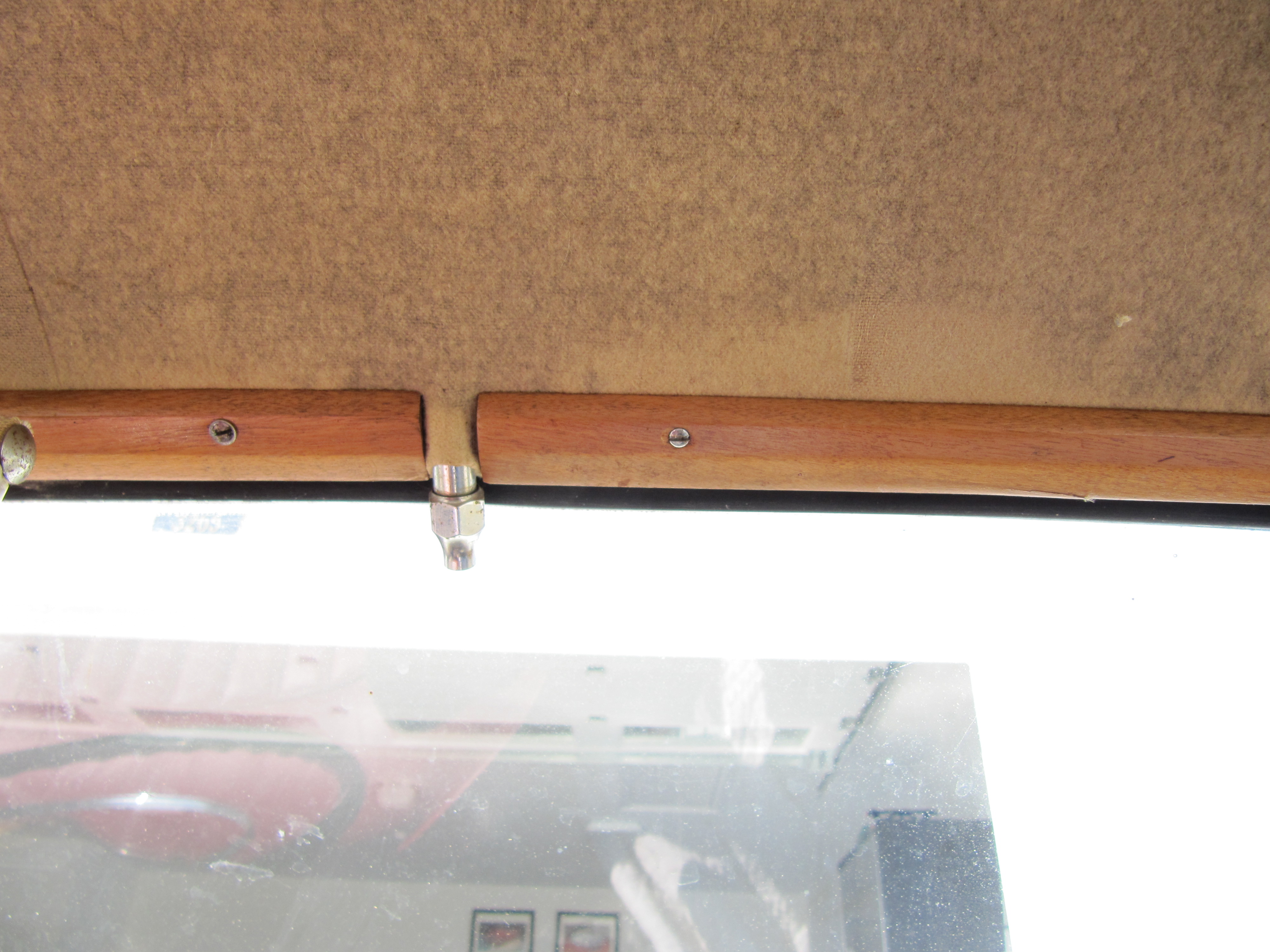
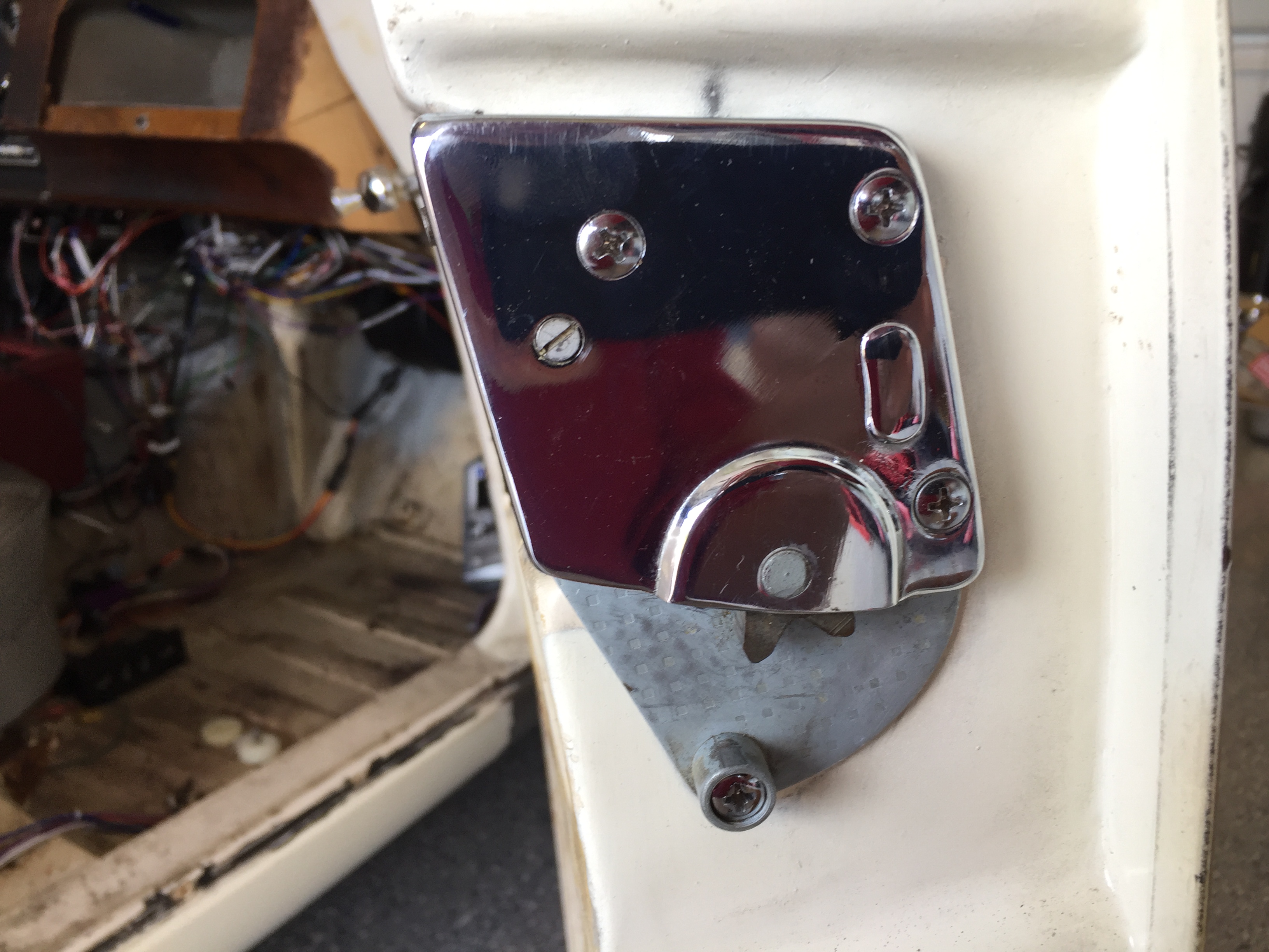
As it turns out, most of the mounting bracket is covered by the roof liner when installed so it will need to be installed prior to the roof liner going in the car. The image below shows the proper installation.
Before reassembling the mirror I need to have the glass resilvered.

Interior Mirror Mounting Bracket, Post and Locking Nut
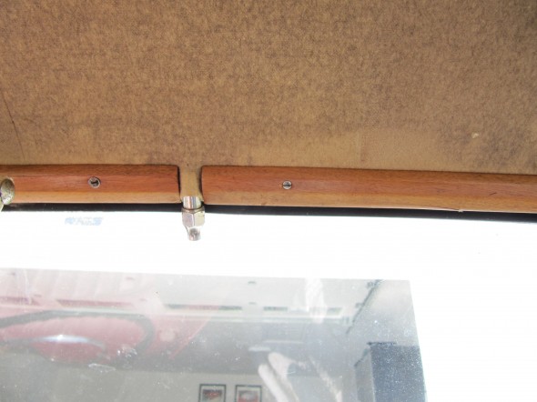
Mirror Mounting Bracket Installed
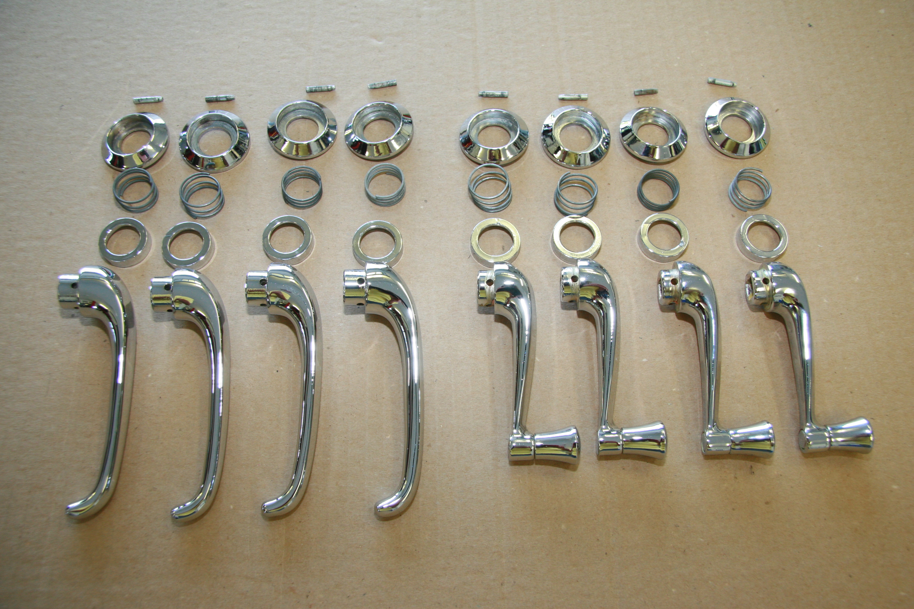
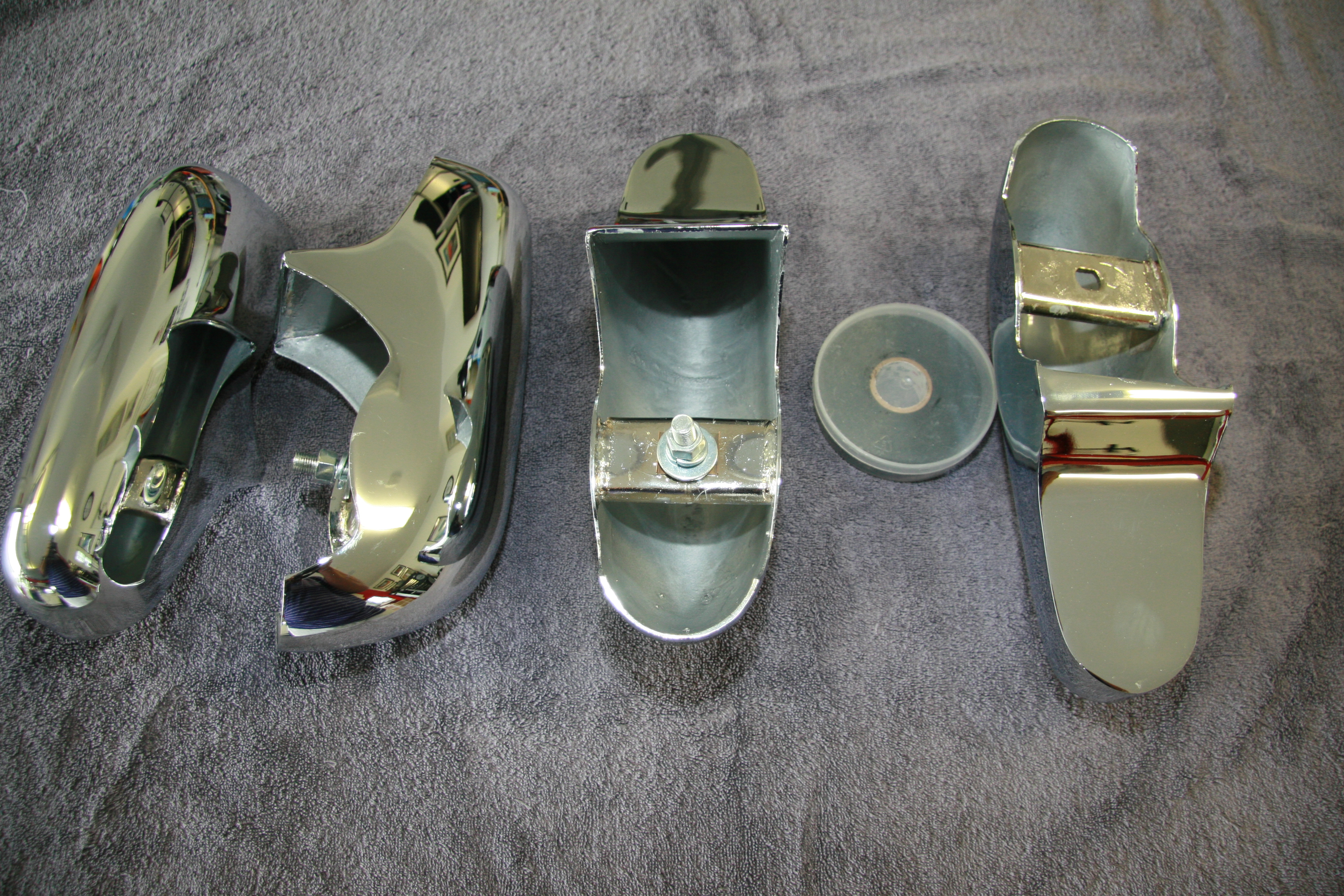
Sun Visor Friction Pivot Assembly
I disassembled the sun visors pulling out the friction rod for rechroming.
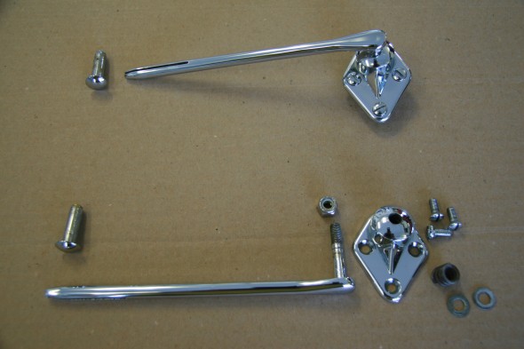
Sun Visor Friction Pivot Assembly Rechromed
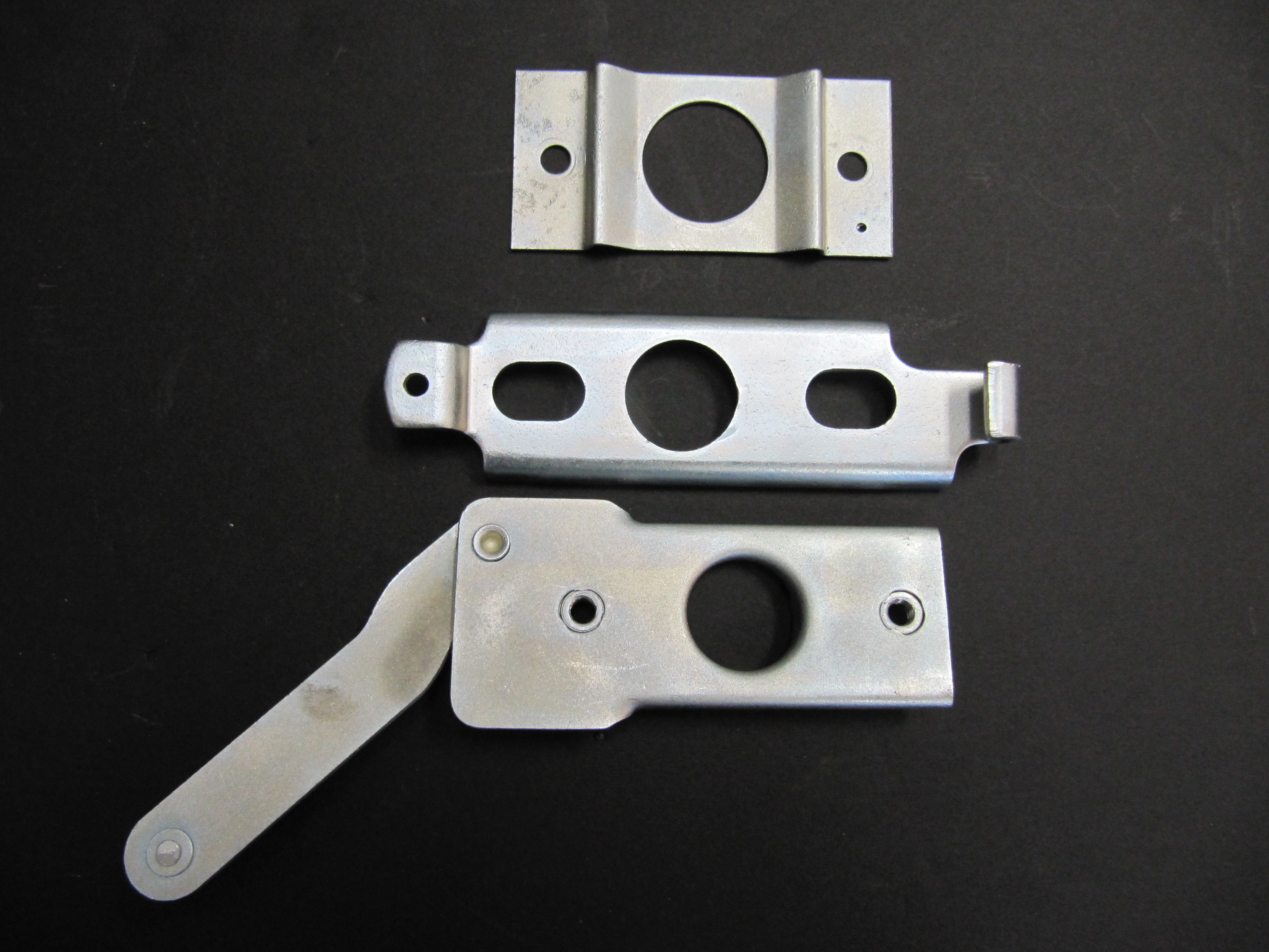
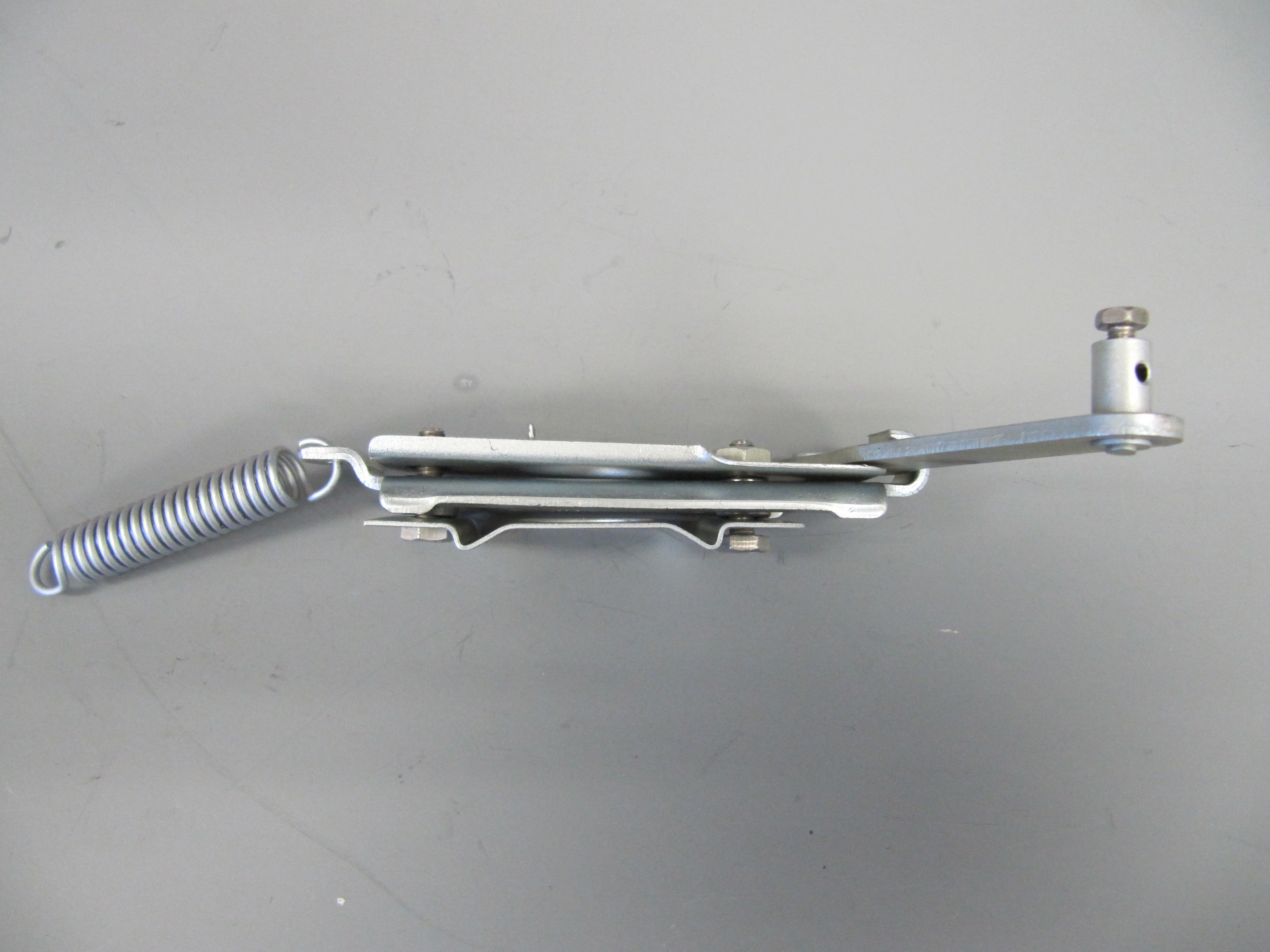
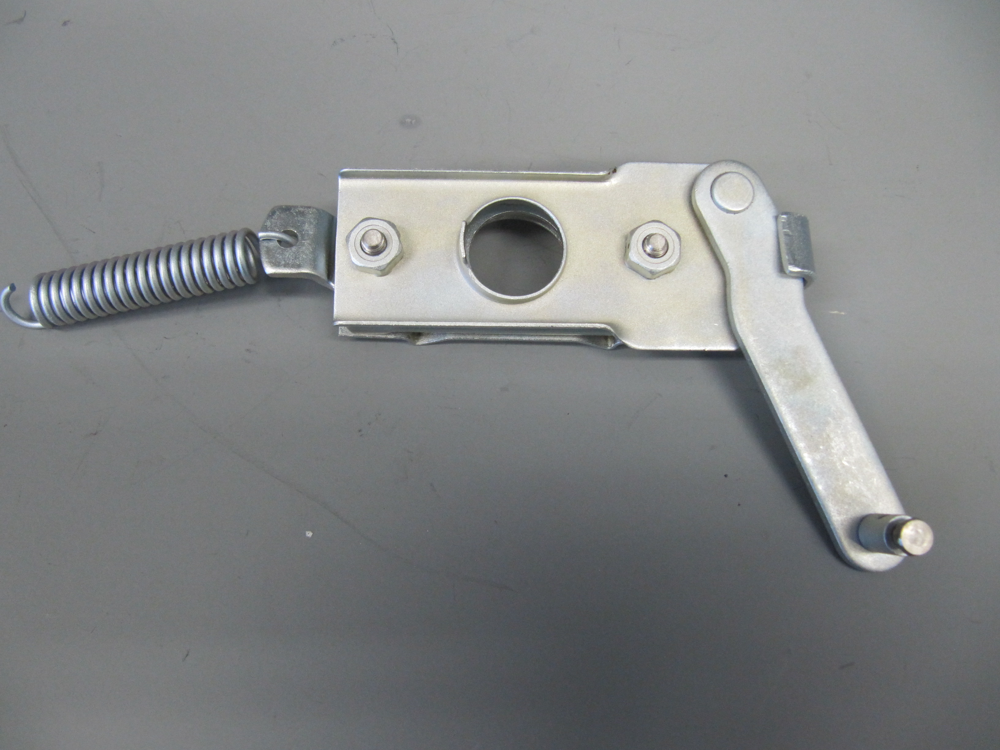
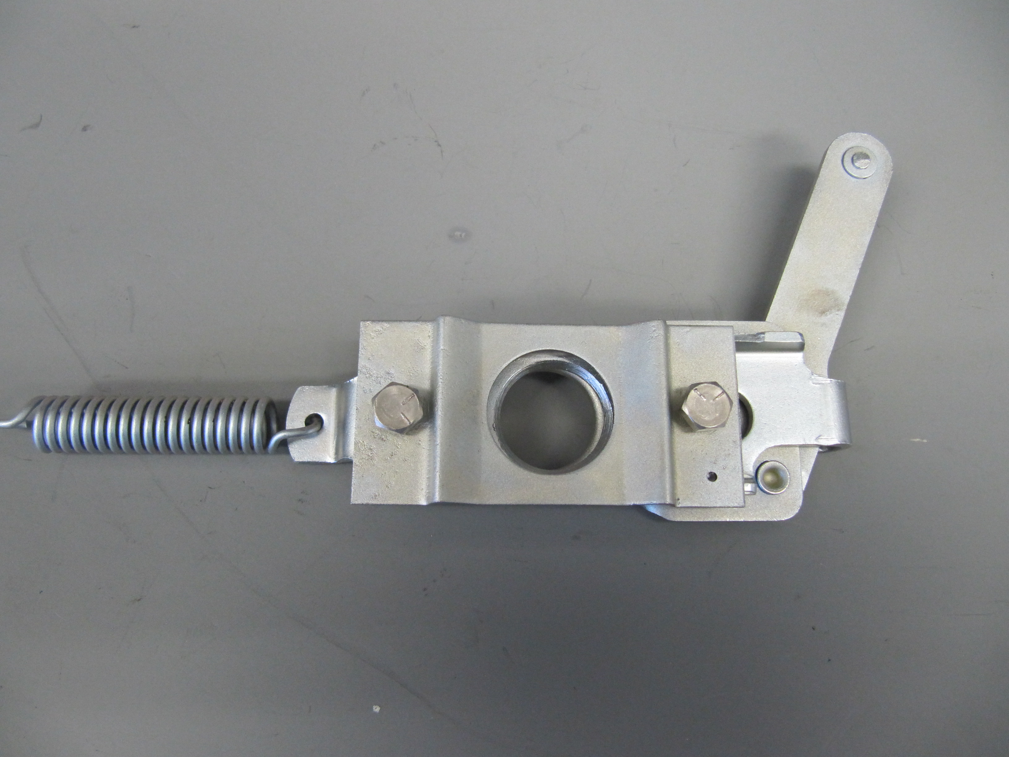
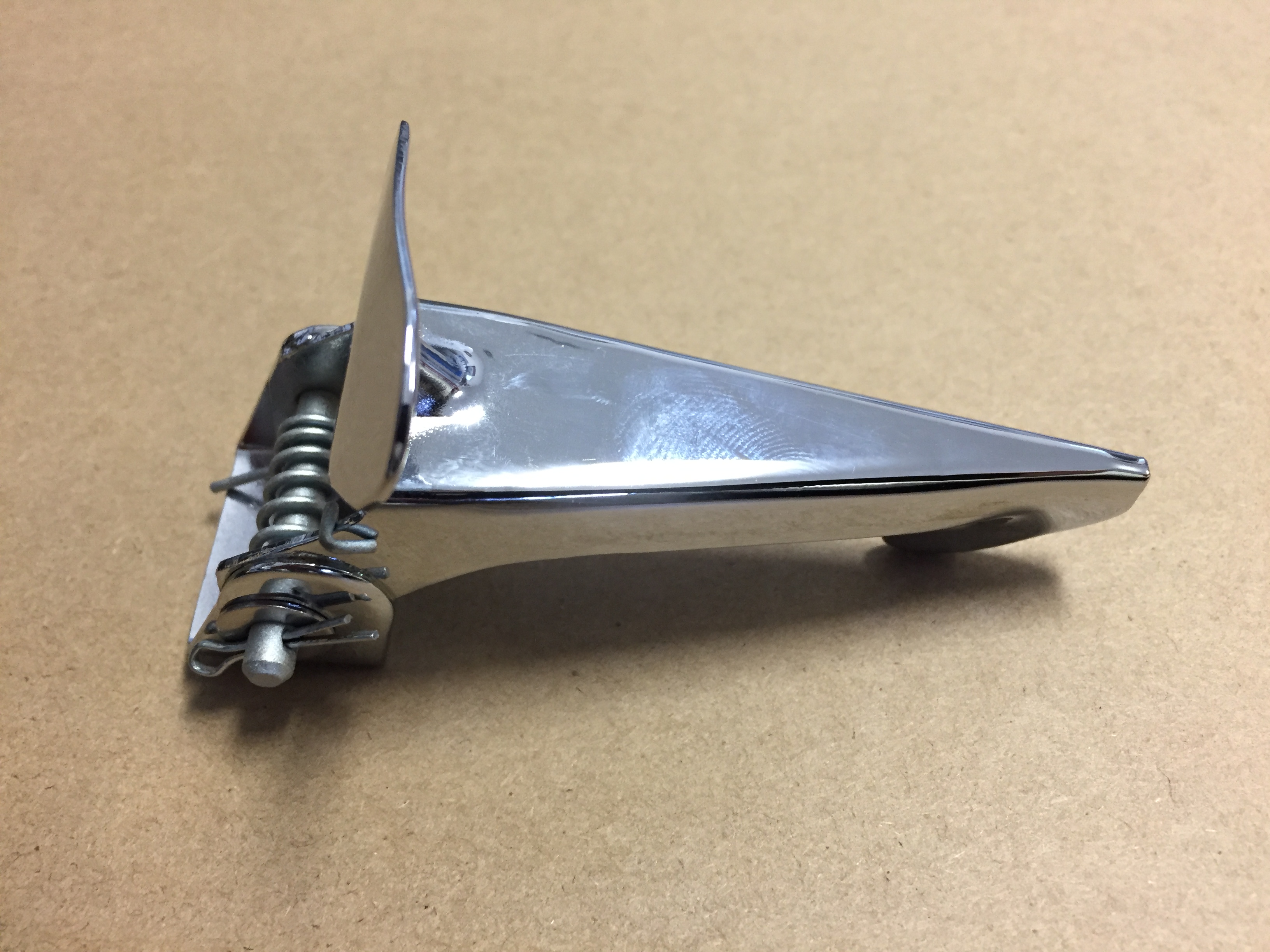
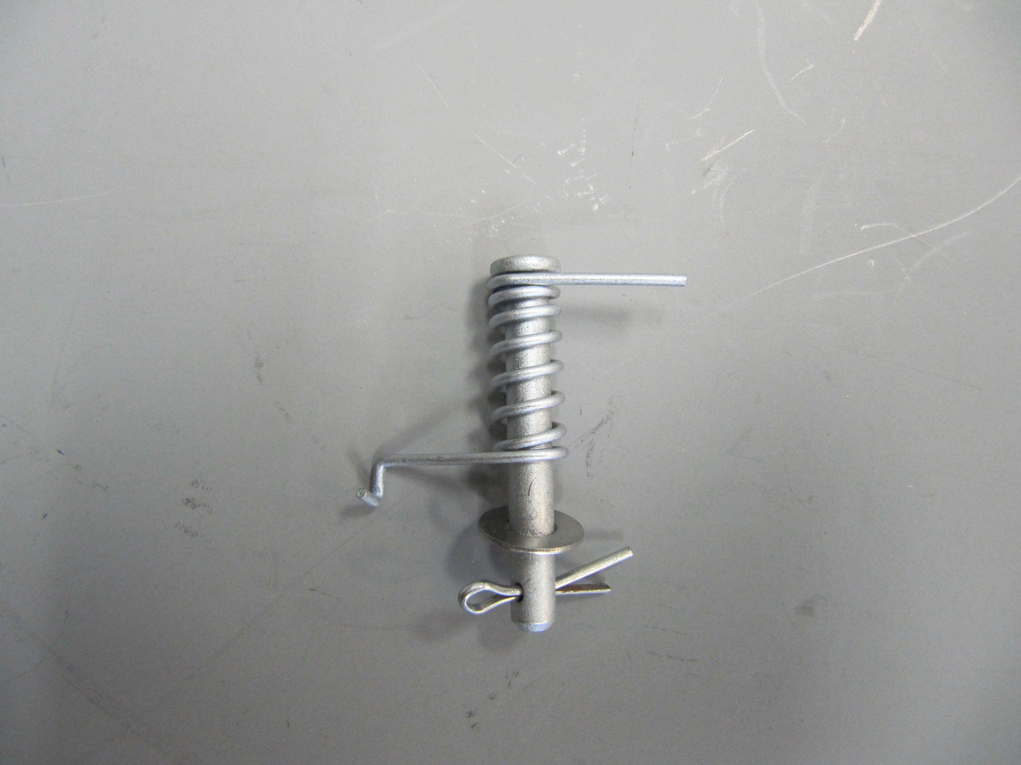
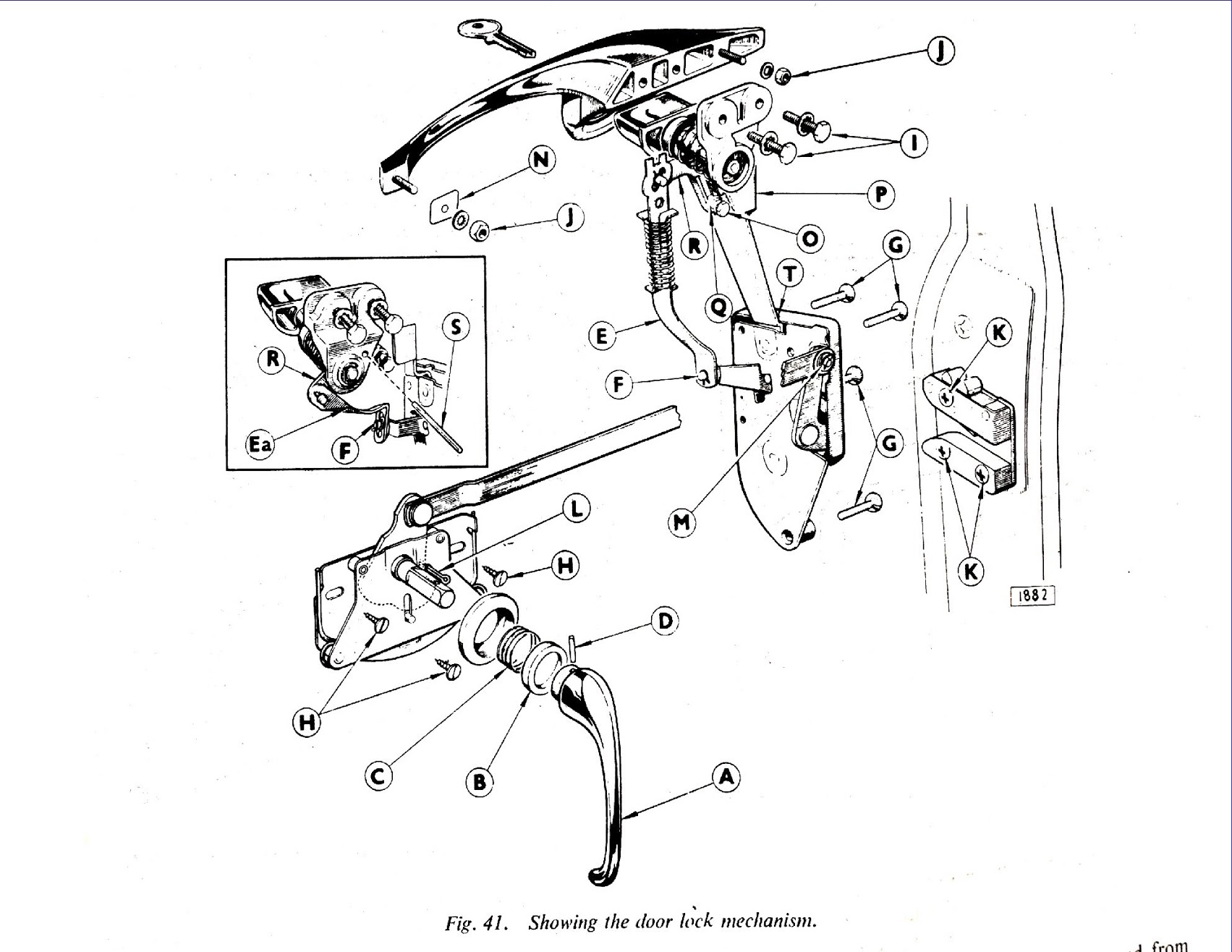
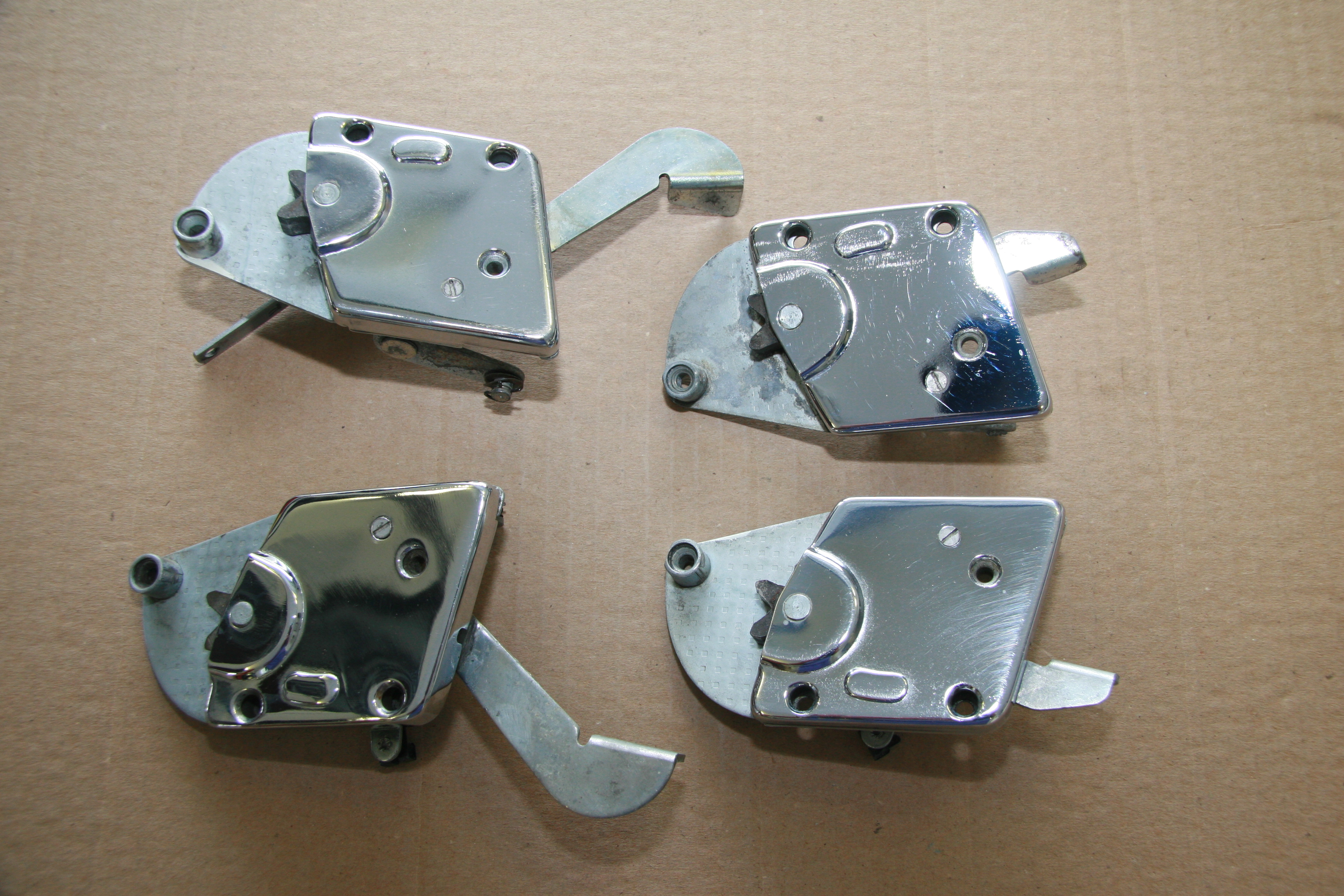
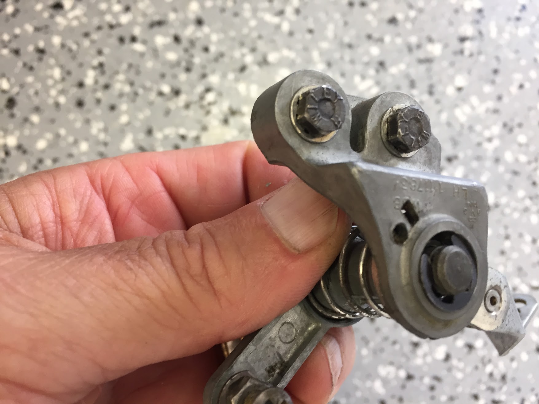
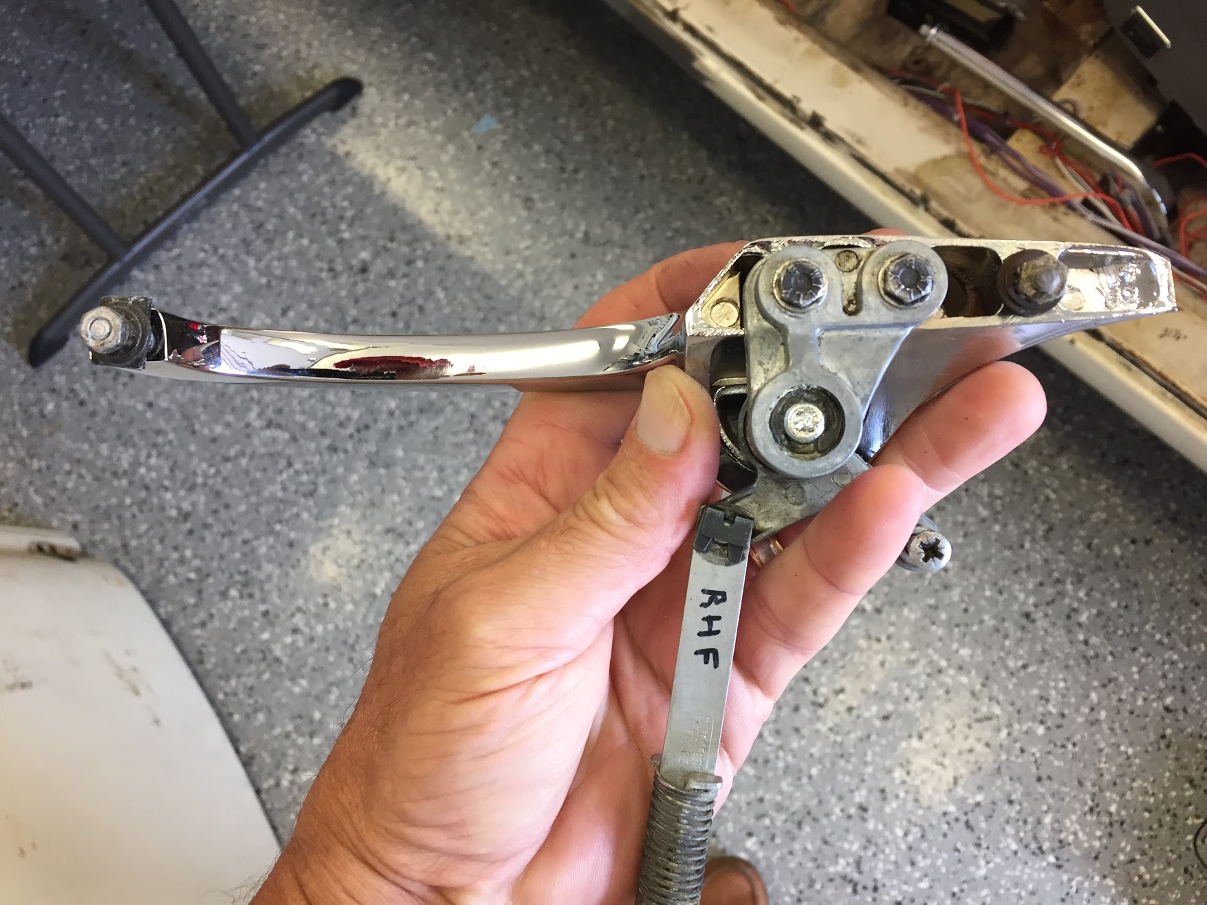
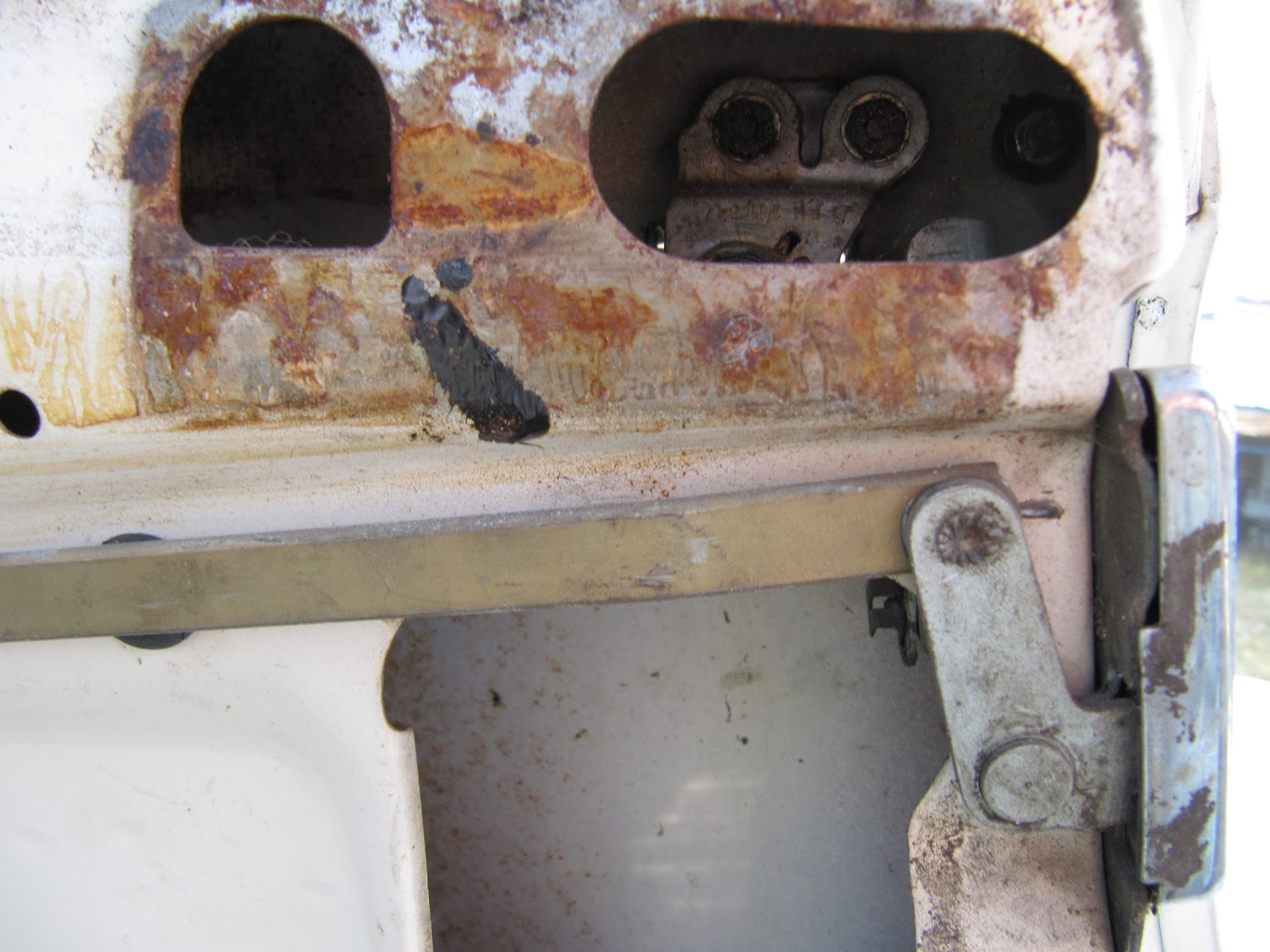
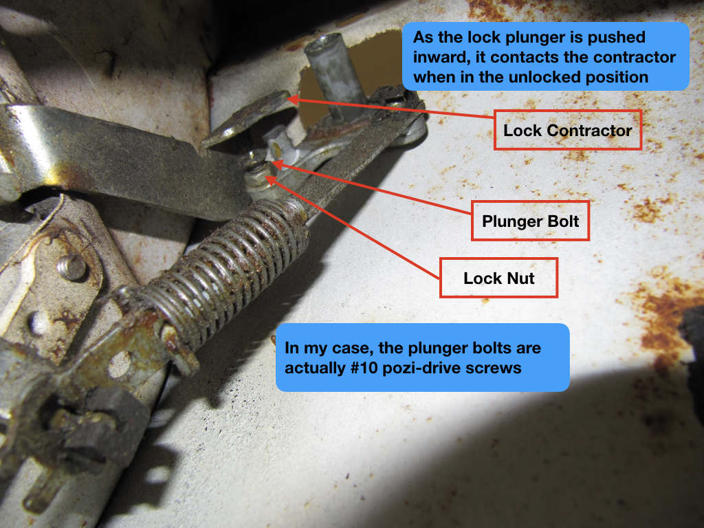
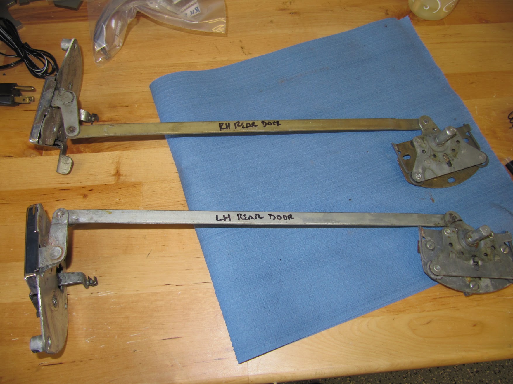
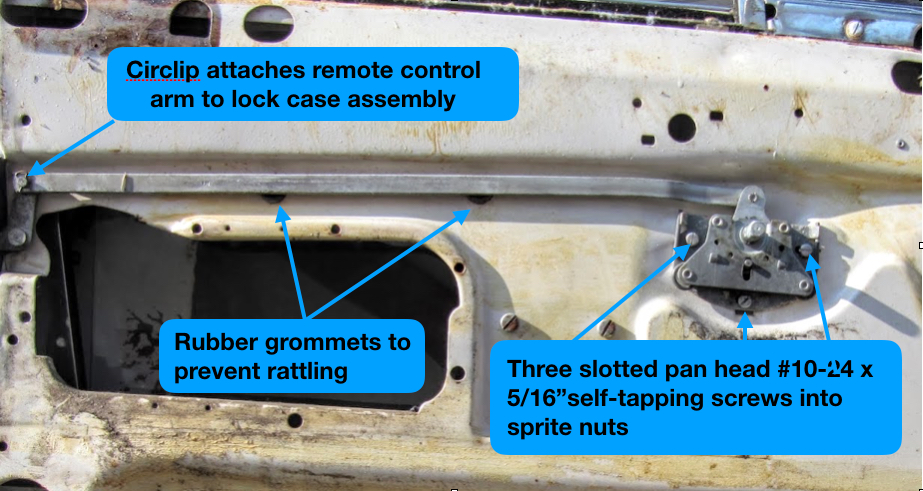
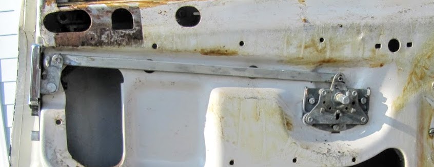
Remote Control Wire and Bonnet Bonnet Lock Assembly
Details located at: https://valvechatter.com/?cat=677
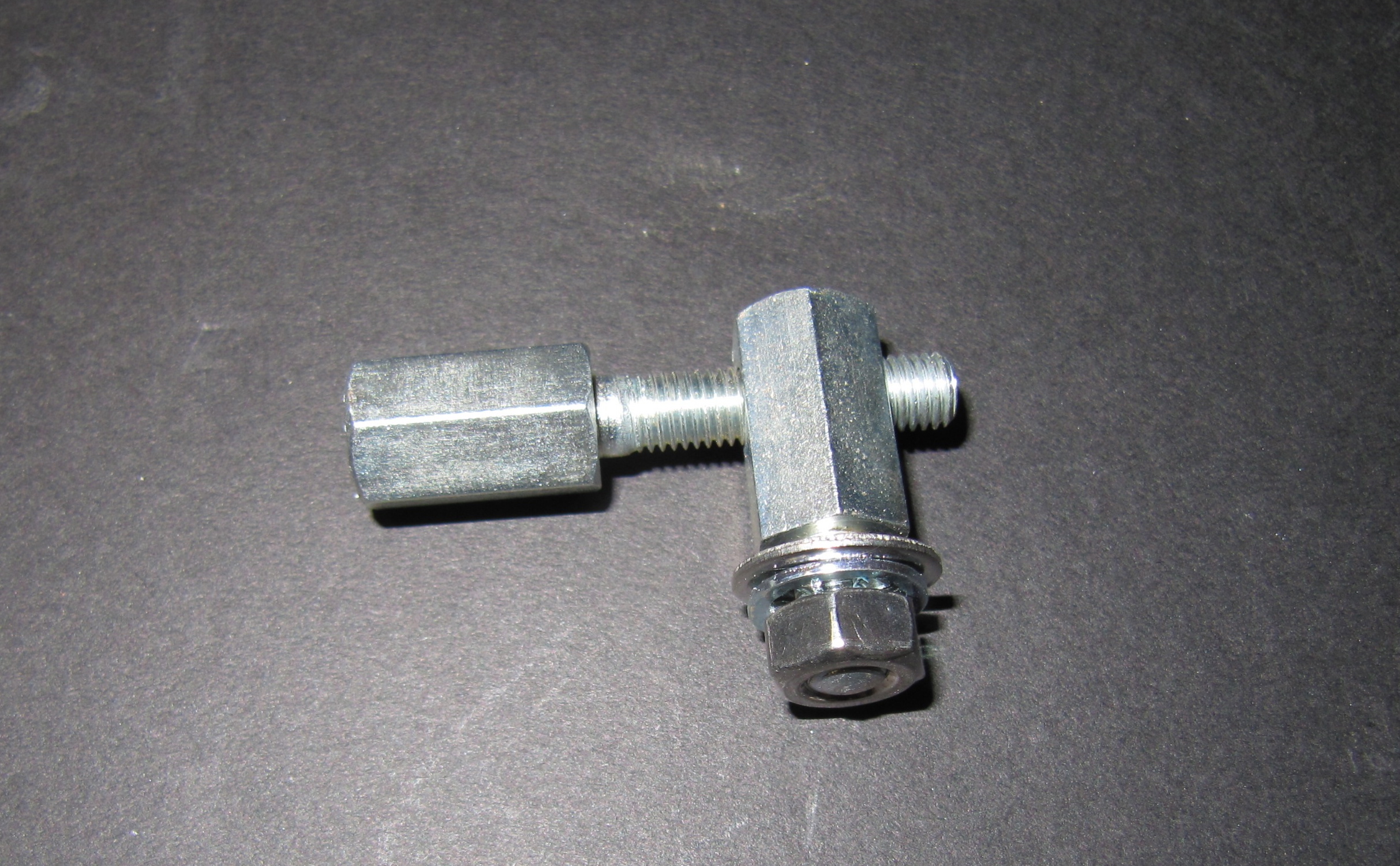
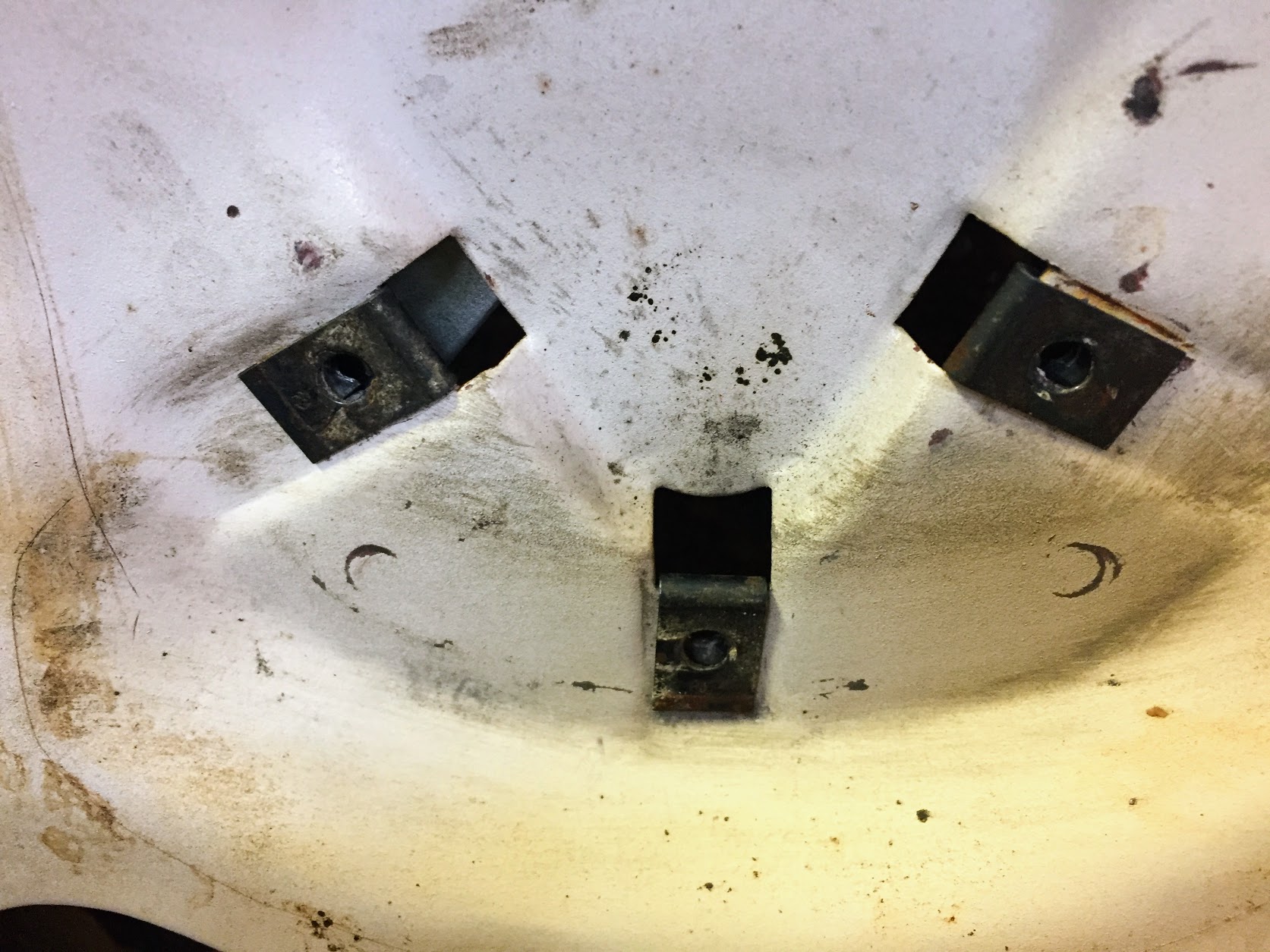
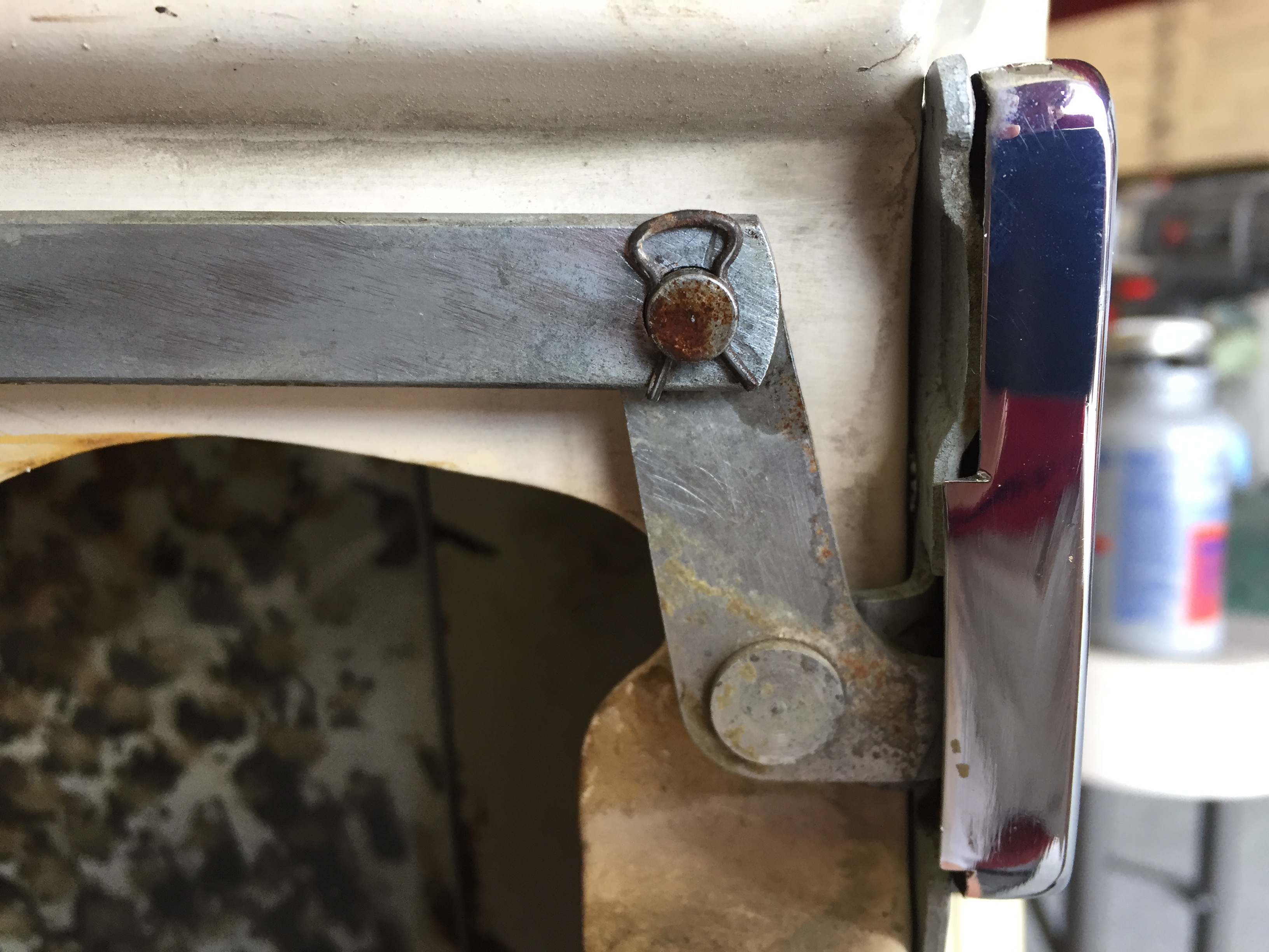
Adjuster & Abutment
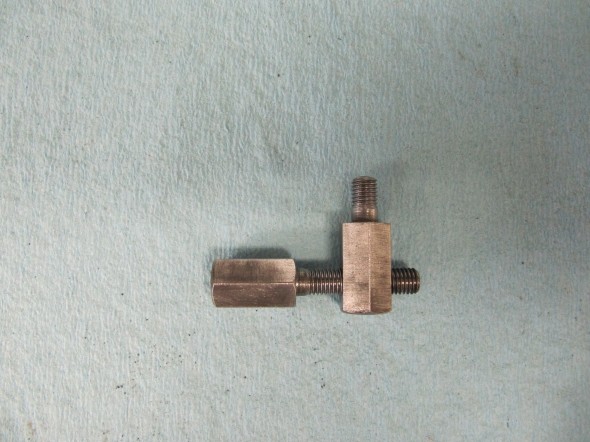
Adjuster & Abutment
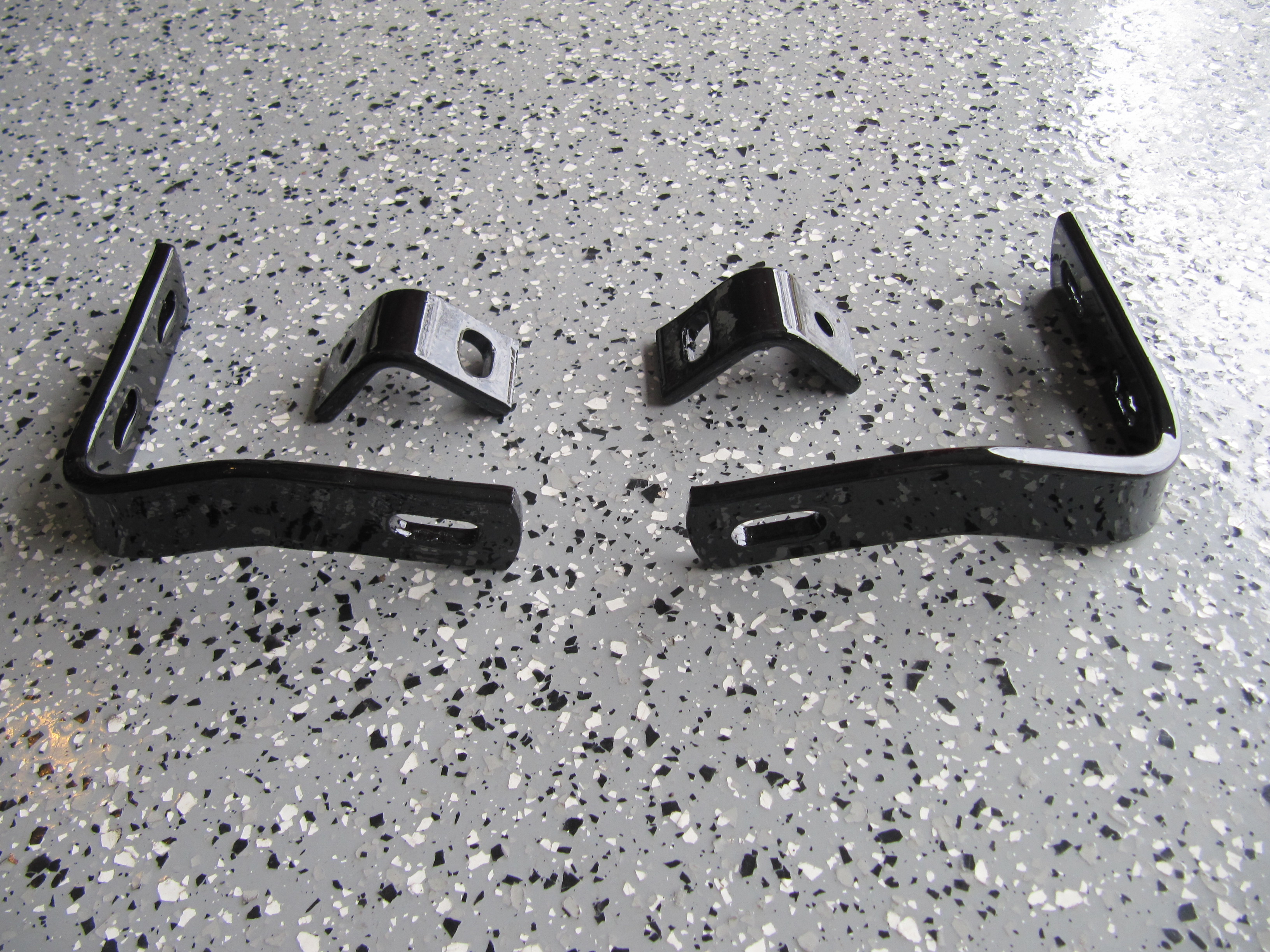
Steering Column, Lower Mounting Assembly
I media blasted the mounting assembly and prepared it for fresh paint:

Steering Column Lower Mounting Assembly
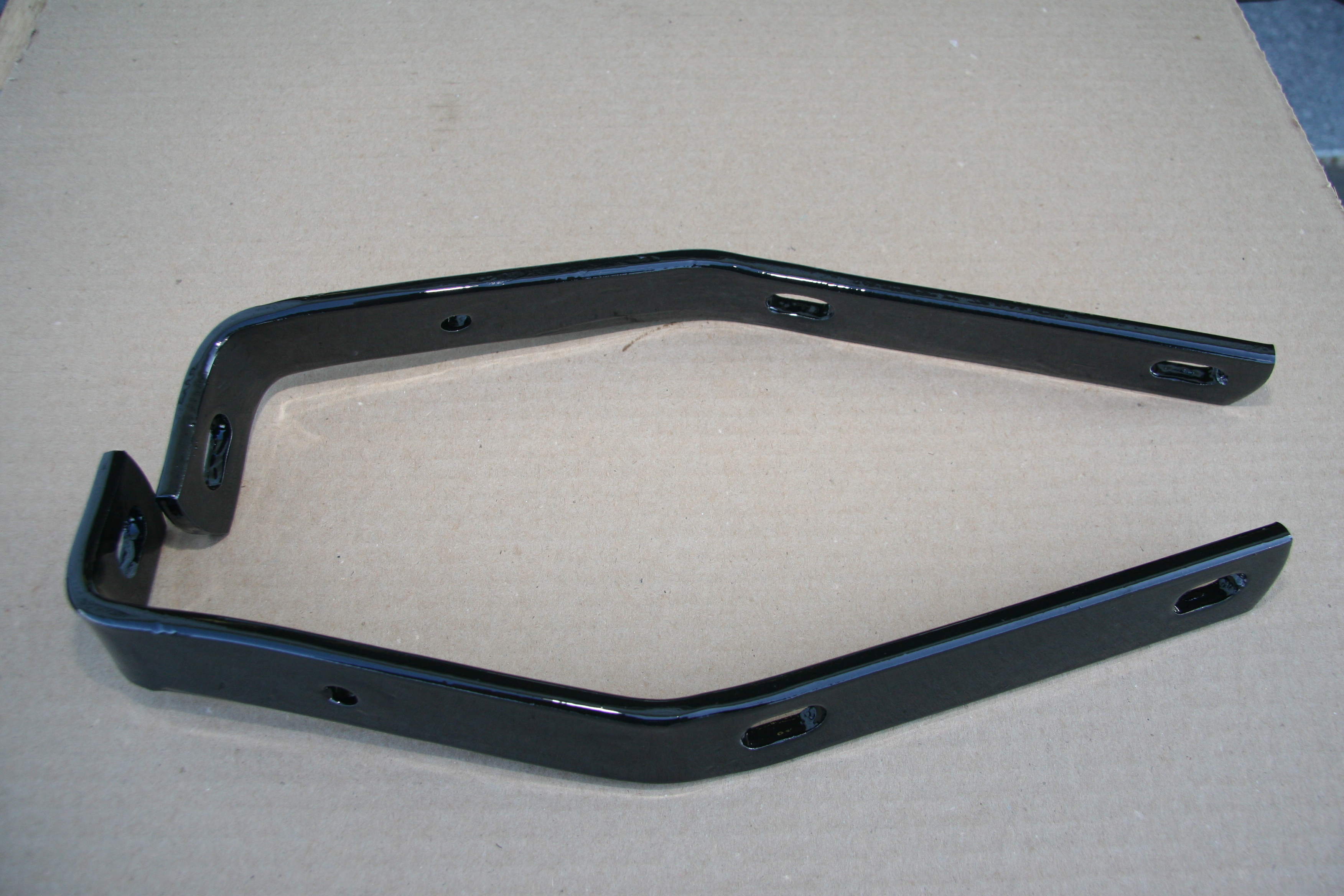
Steering Column Lower Mounting Assembly Painted
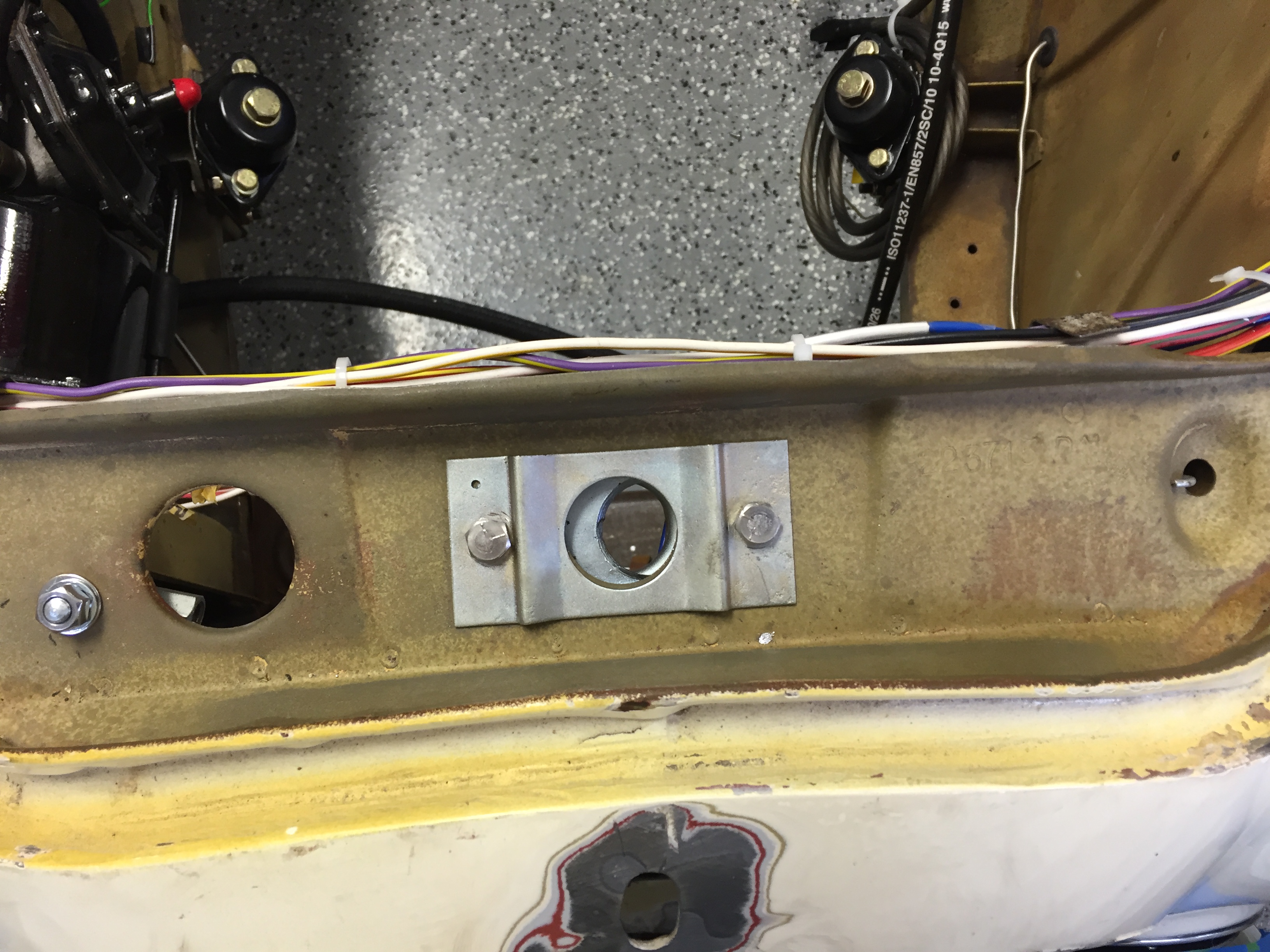
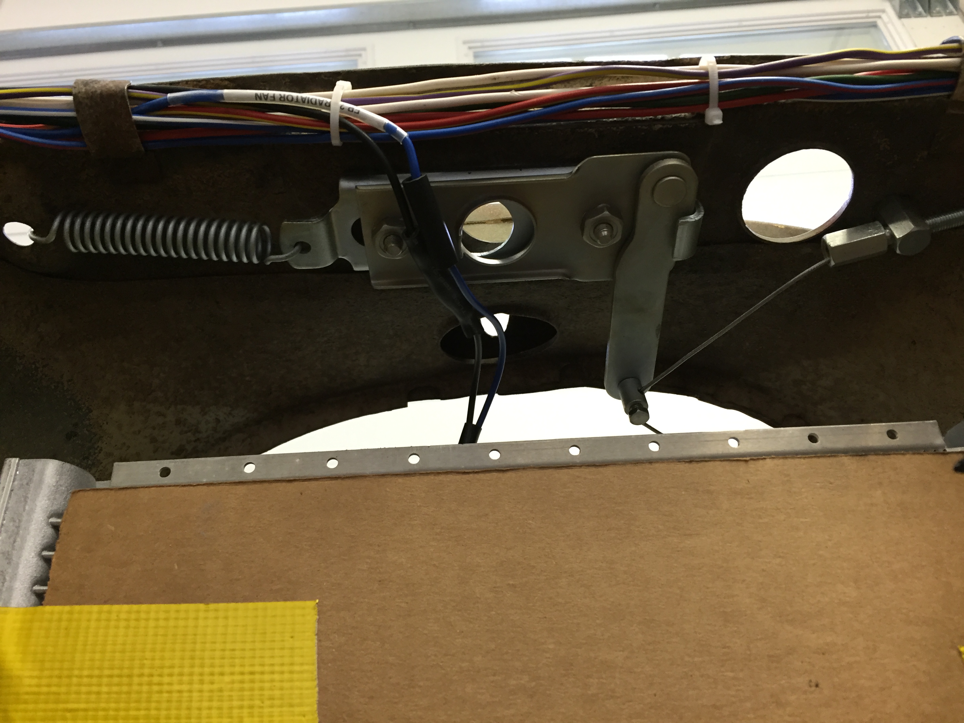
Lower Steering Column Bracket Installed
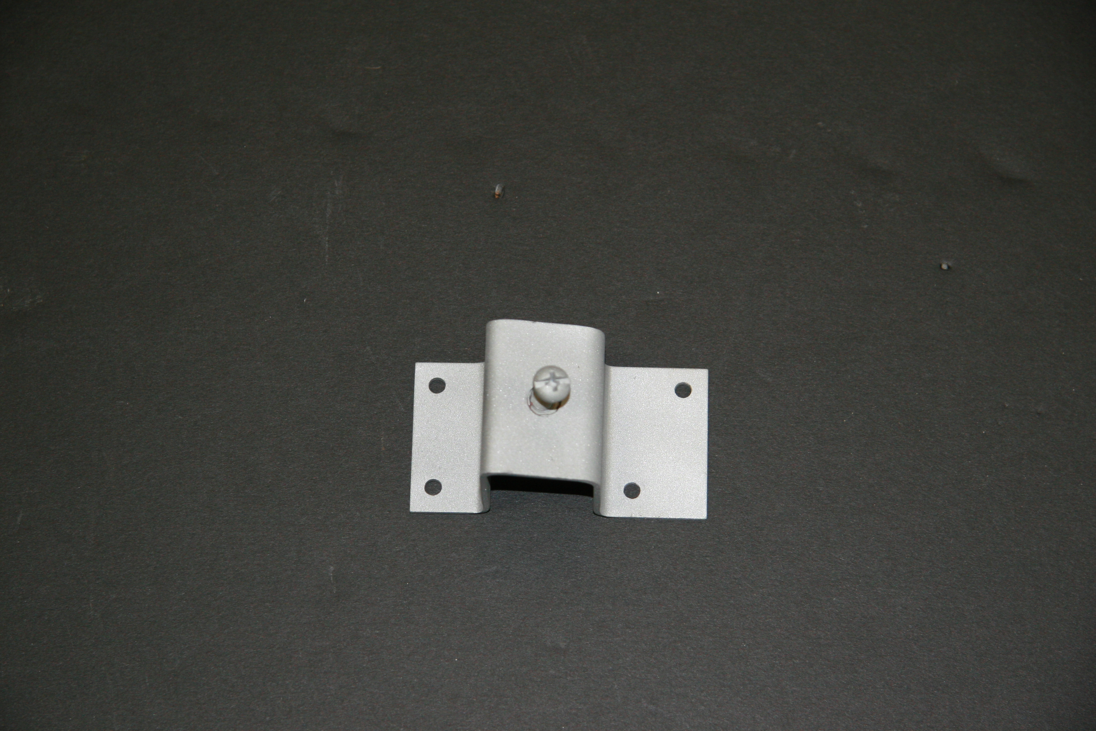
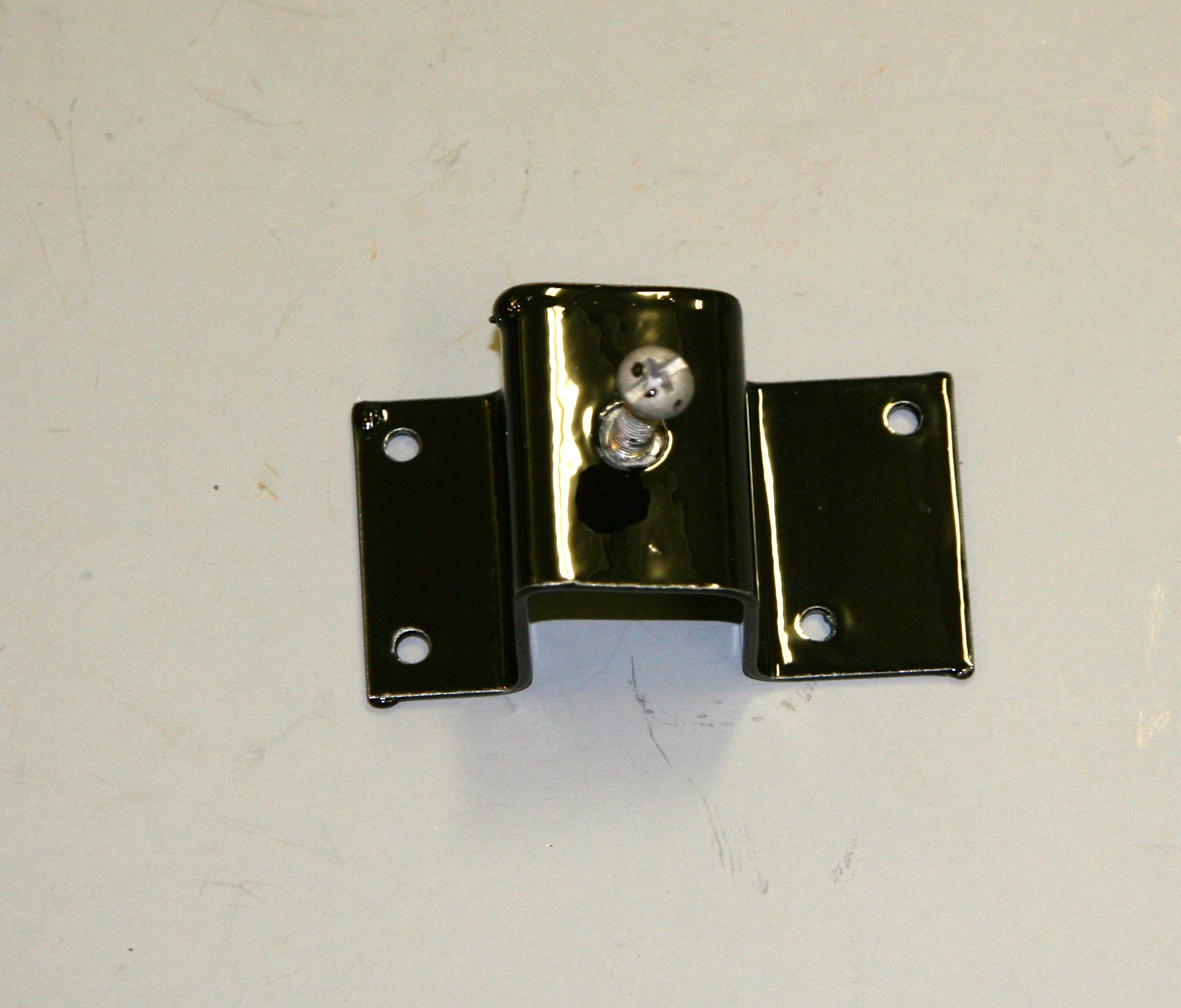
Interior Front Finisher Panel Assembly Mounting Bracket
This little bracket mounts on top of the gearbox cover with four machine screws. The Radio Front Finisher Panel mounts to it with a 1/4″ – 28 x 1″ hex head bolt and shakeproof washer. The bracket is affixed to the gearbox cover with four #8 x 1/4″ machine screws.
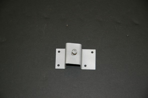
Mounting Bracket to Gearbox

Mounting Bracket Painted
Gearbox Cover
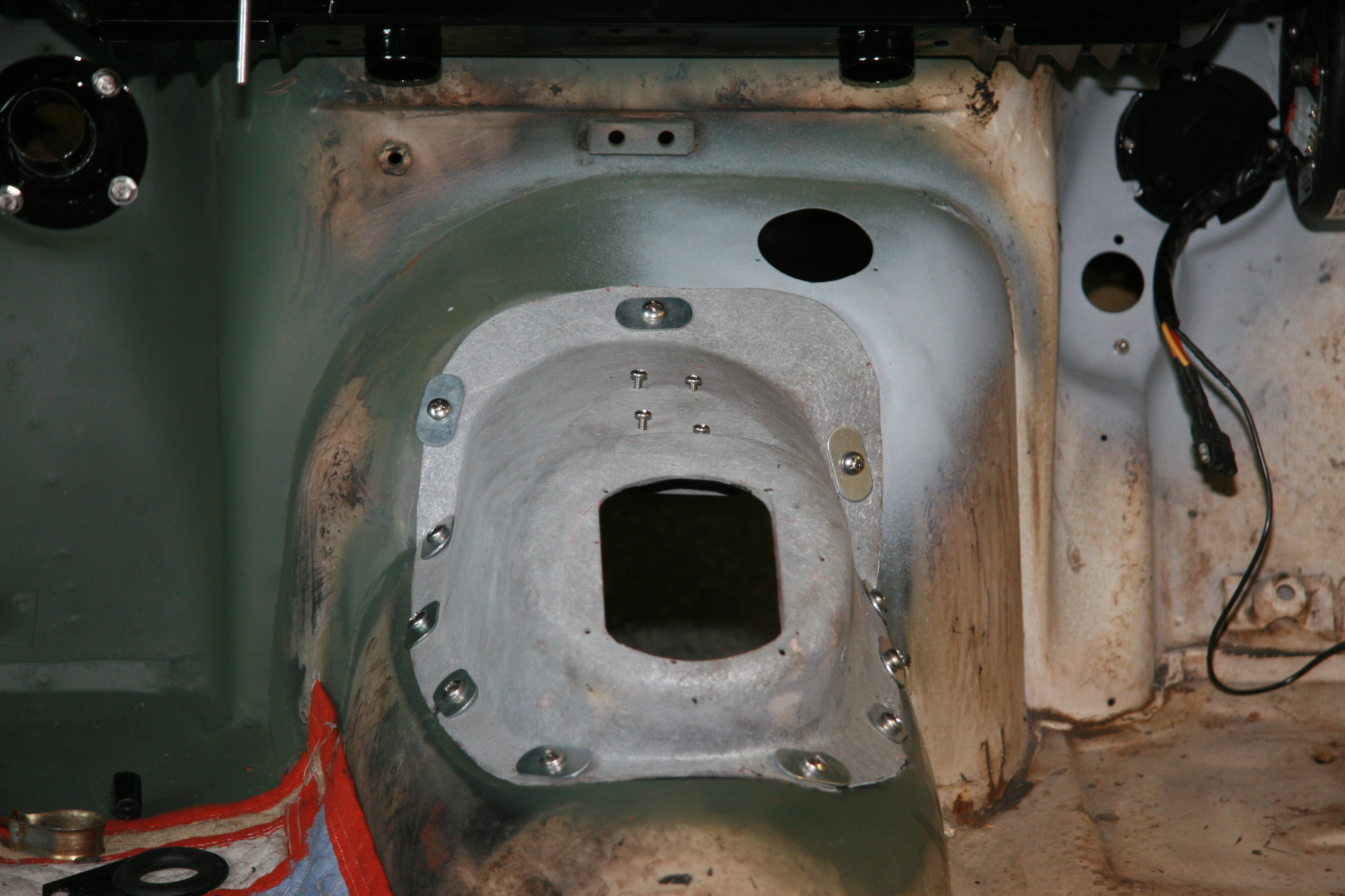
After degreasing and cleaning the cover I media blasted it. While the cover has sen better days, it is functional and can still be used. I did a trial fitting of the cover with new hardware including eleven special washers, eleven, stainless steel 14 x 3/4″ pan head phillips head self-tapping screws and eleven spire nuts or J-Style slip-on nuts. The original screws were slotted.
To ease access, I assume for a clutch replacement, the sheet metal around the gearbox had been cut, but John Stefanik was able to get it all welded back together. There was originally a “tar paper” gasket around the outside edge of the tunnel. I intend to use Dynamat Extreme for that purpose upon final assembly.
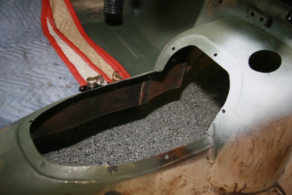
Repaired Gearbox Tunnel
Gearbox Cover Special Washer Sheet Metal Screw and J Style Slip-on Nut

Gearbox Cover Installed
Gearbox Cover Installed
Grille Assembly in Front Finisher Panel
I had the this radio speaker grille rechromed and it came out quite well!
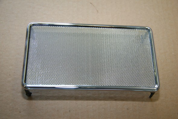
Grill Assembly in Front Finisher Panel New Chrome
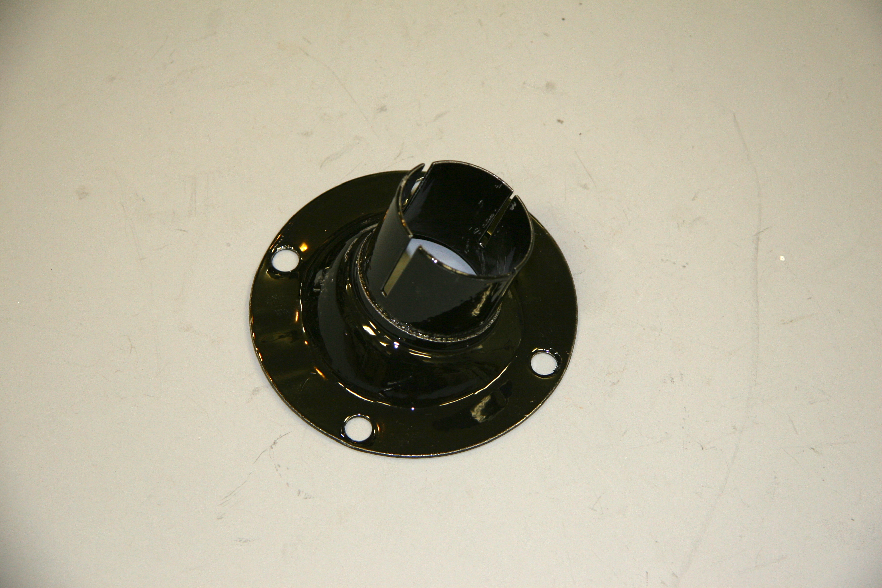
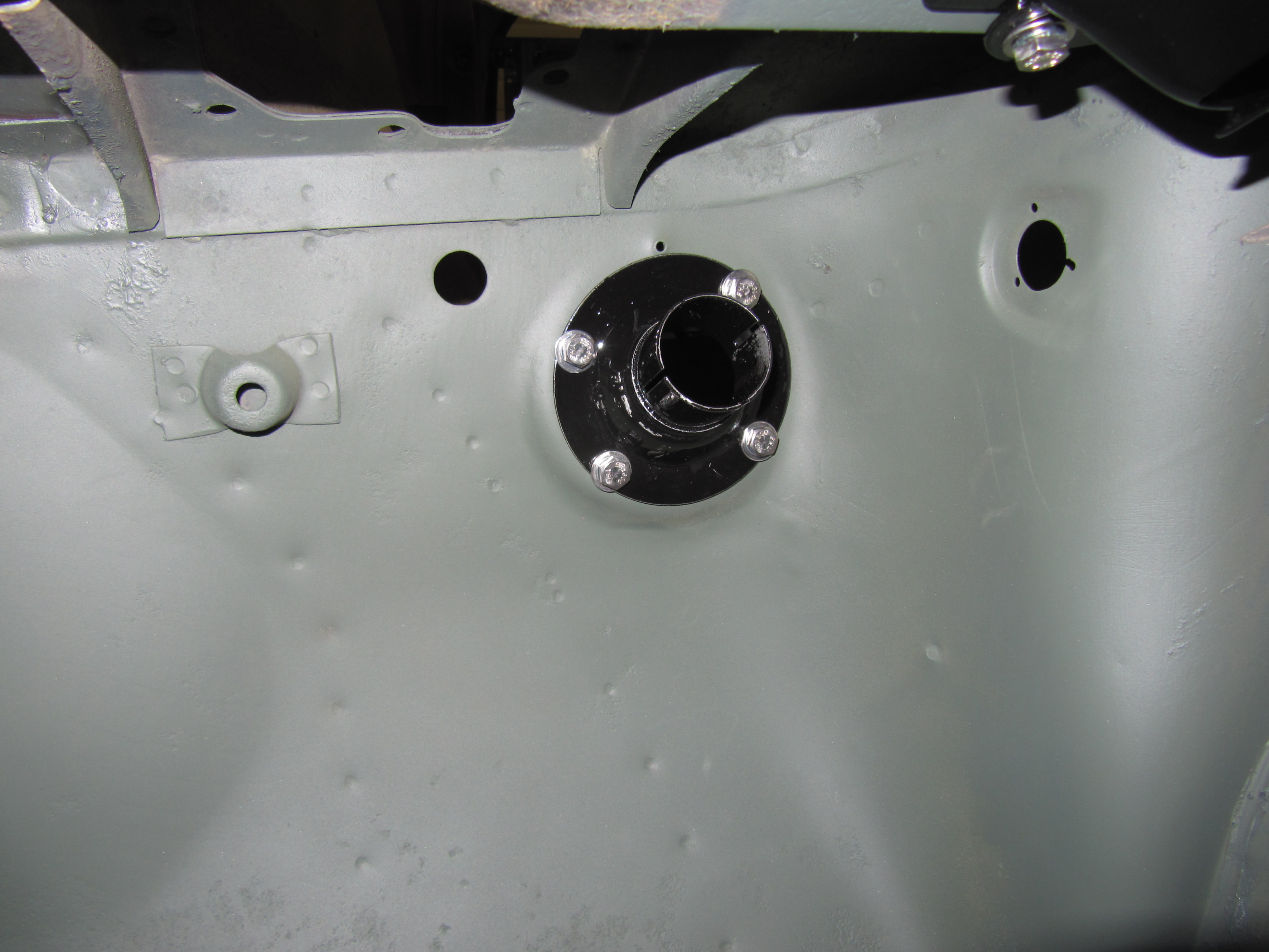
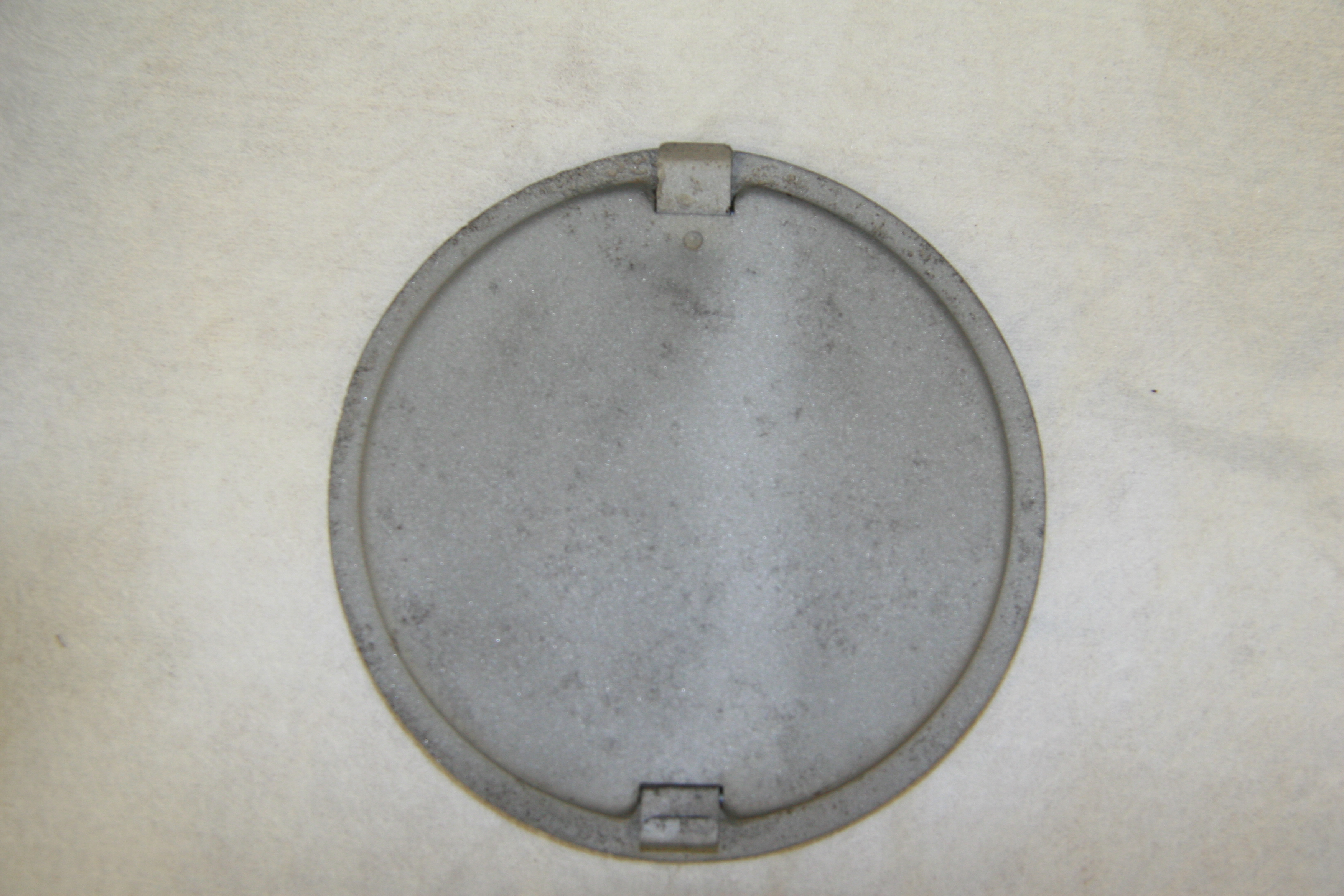
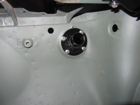
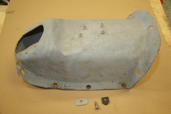
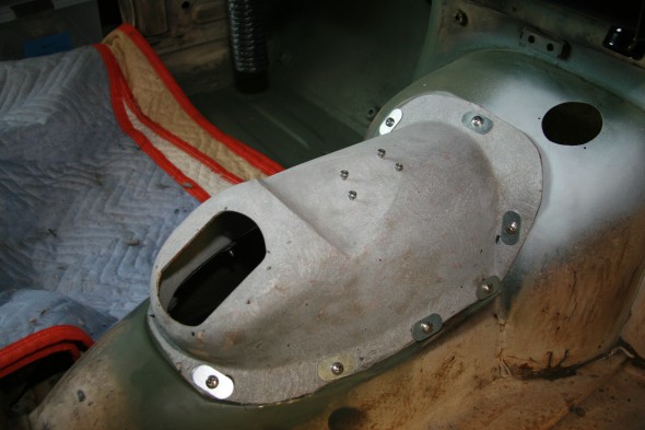
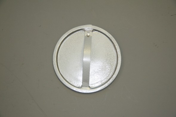
Cover, On Trunk Floor, Giving Access to Fuel Gauge Unit
This little piece may have been the rustiest single component on the car. While not perfect, I was able to bring it back to life! Here are the before and after images:
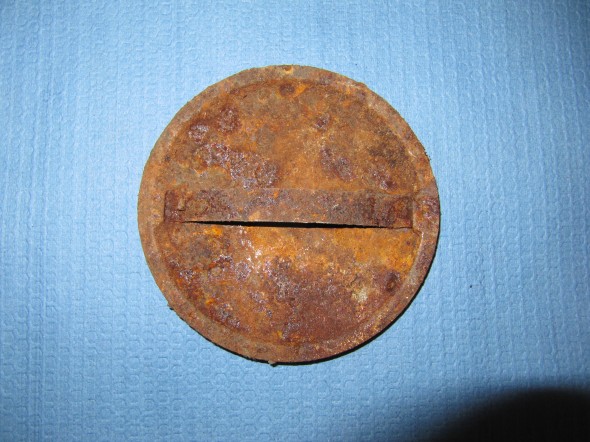
Fuel Gauge Cover
Fuel Gauge Cover
These are a few images of work along the way. First rust remover and body prep and then body filler:
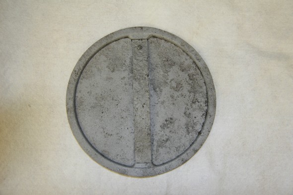
Cover

Cover Underside
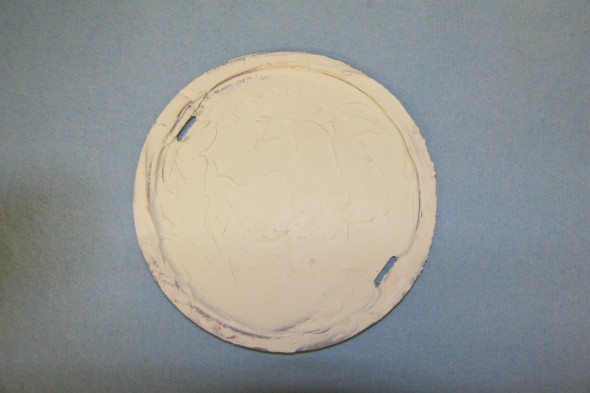
Cover with Filler
The little strap for the cover was too far gone, so I made a new one with some 26 gauge stock and riveted it to the cover.
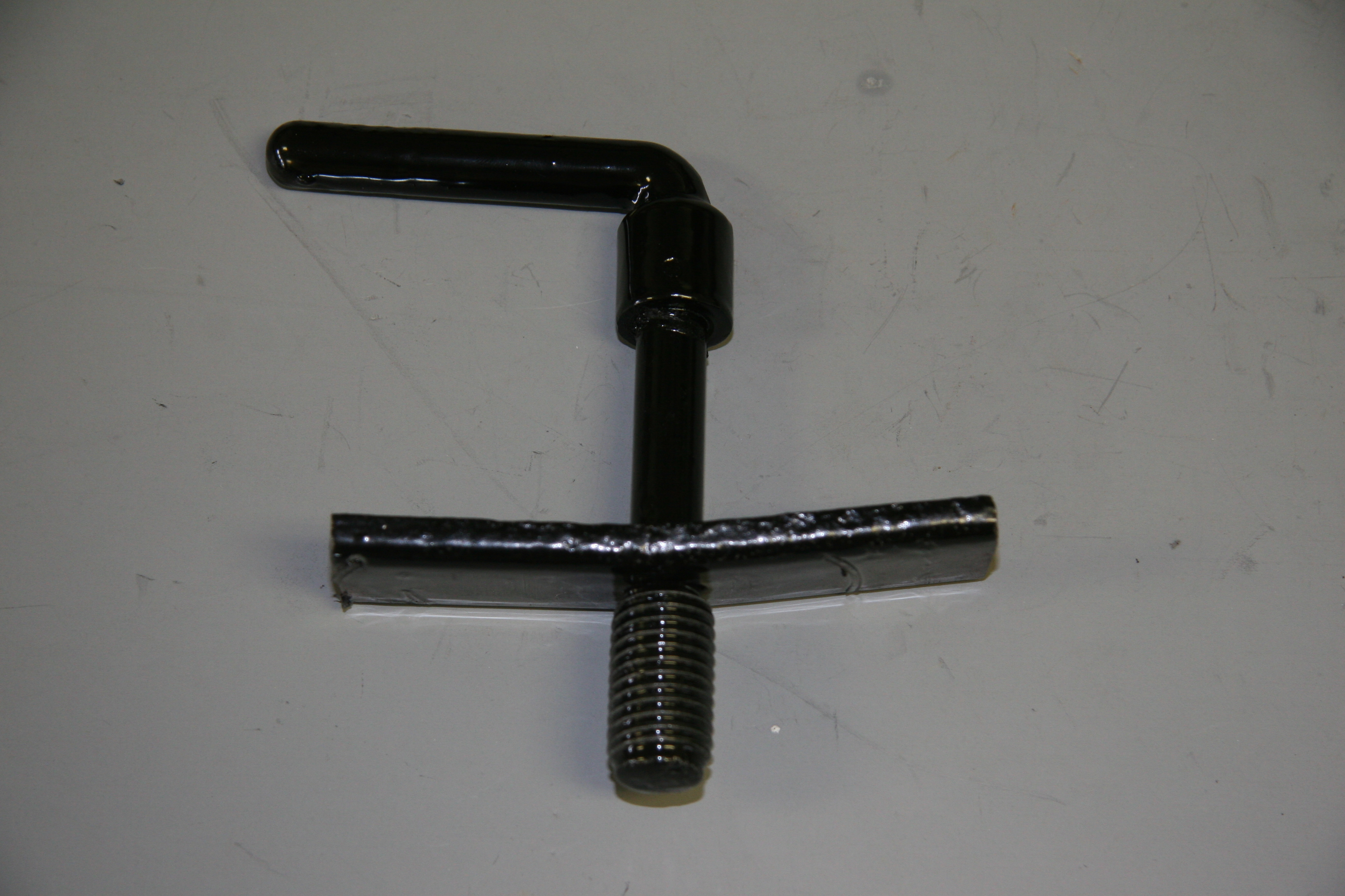
Spare Wheel Clamp Assembly
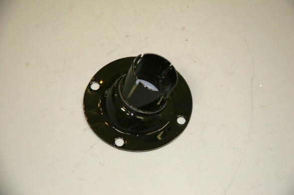
This device screws into a threaded plate in the spare wheel cavity in the boot to secure the spare tire. It was badly rusted but I media basted and painted with POR 15 making it serviceable.
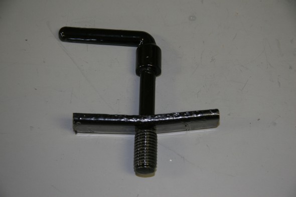
Painted Spare Wheel Clamp Assembly
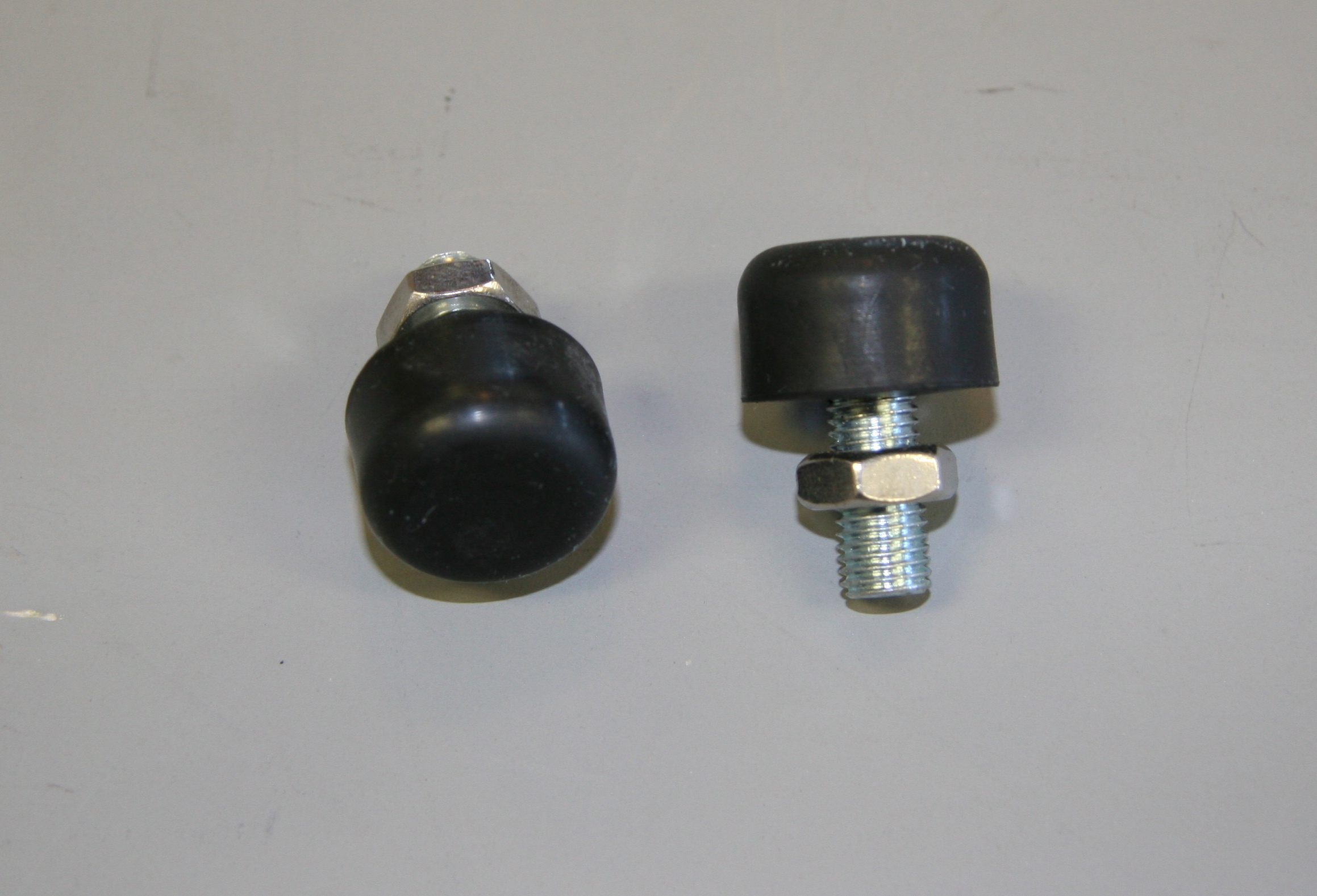
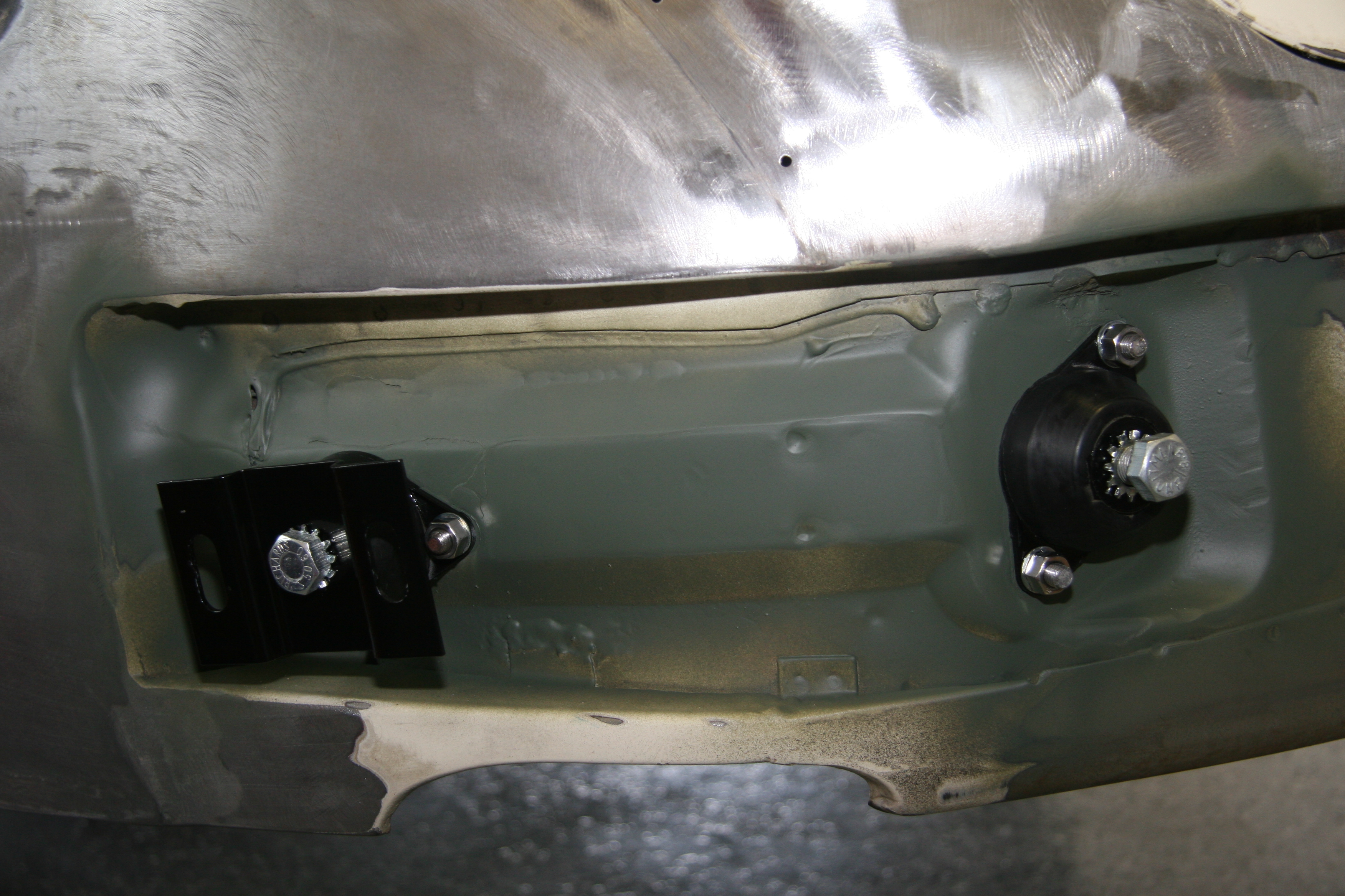
Rubber Buffer, At Front Corners, For Bonnet Stop
I replaced the bolt and nut as well as installing new rubber stops on the bolt:
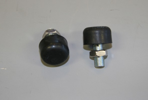
Bonnet Rubber Buffers
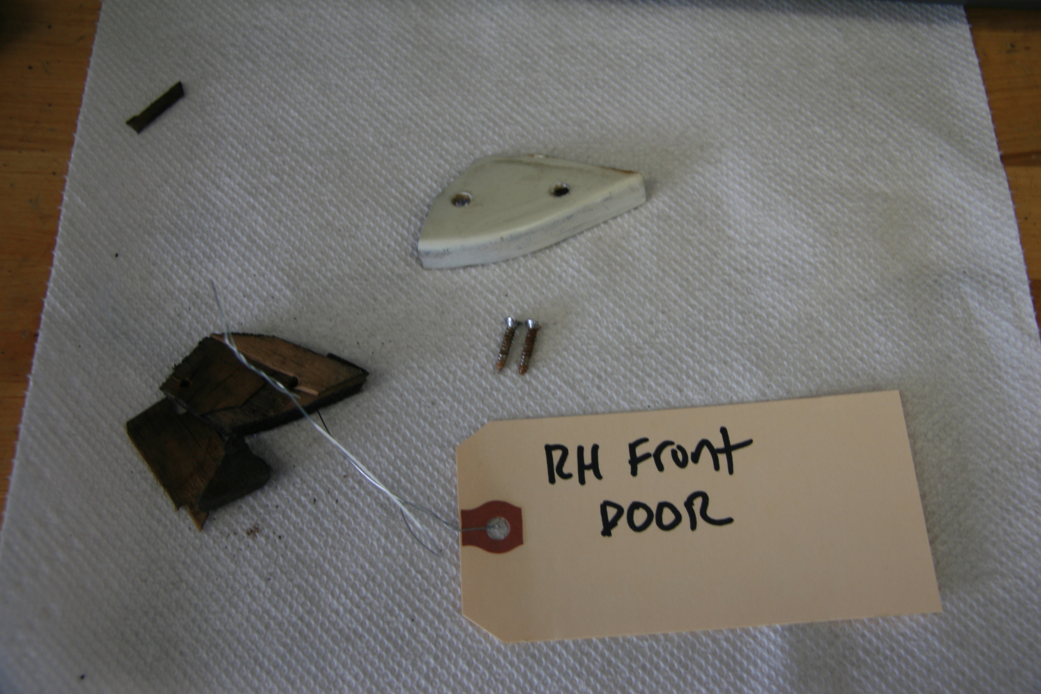
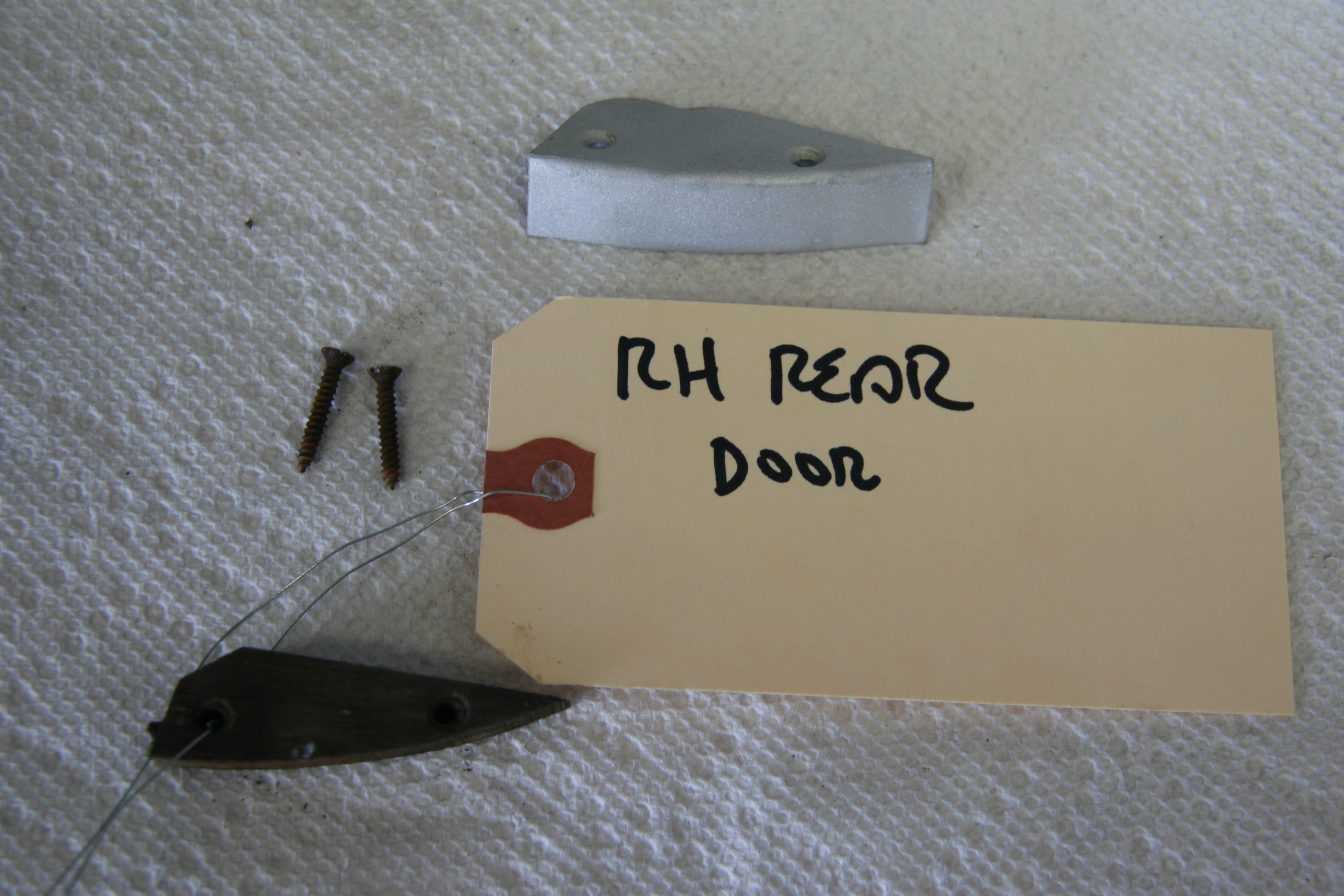
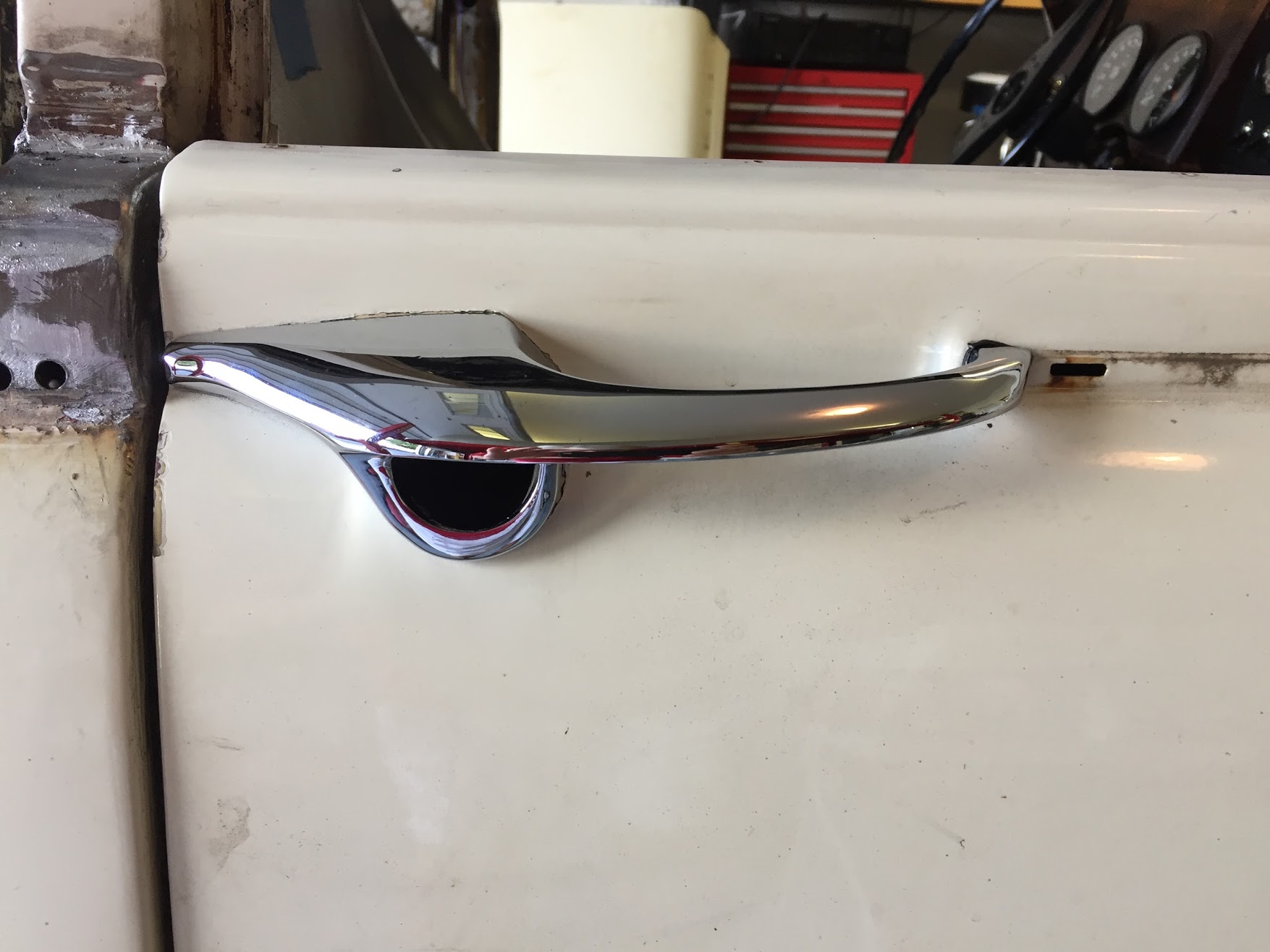
Door Filler Pieces on the Shut Face Panel
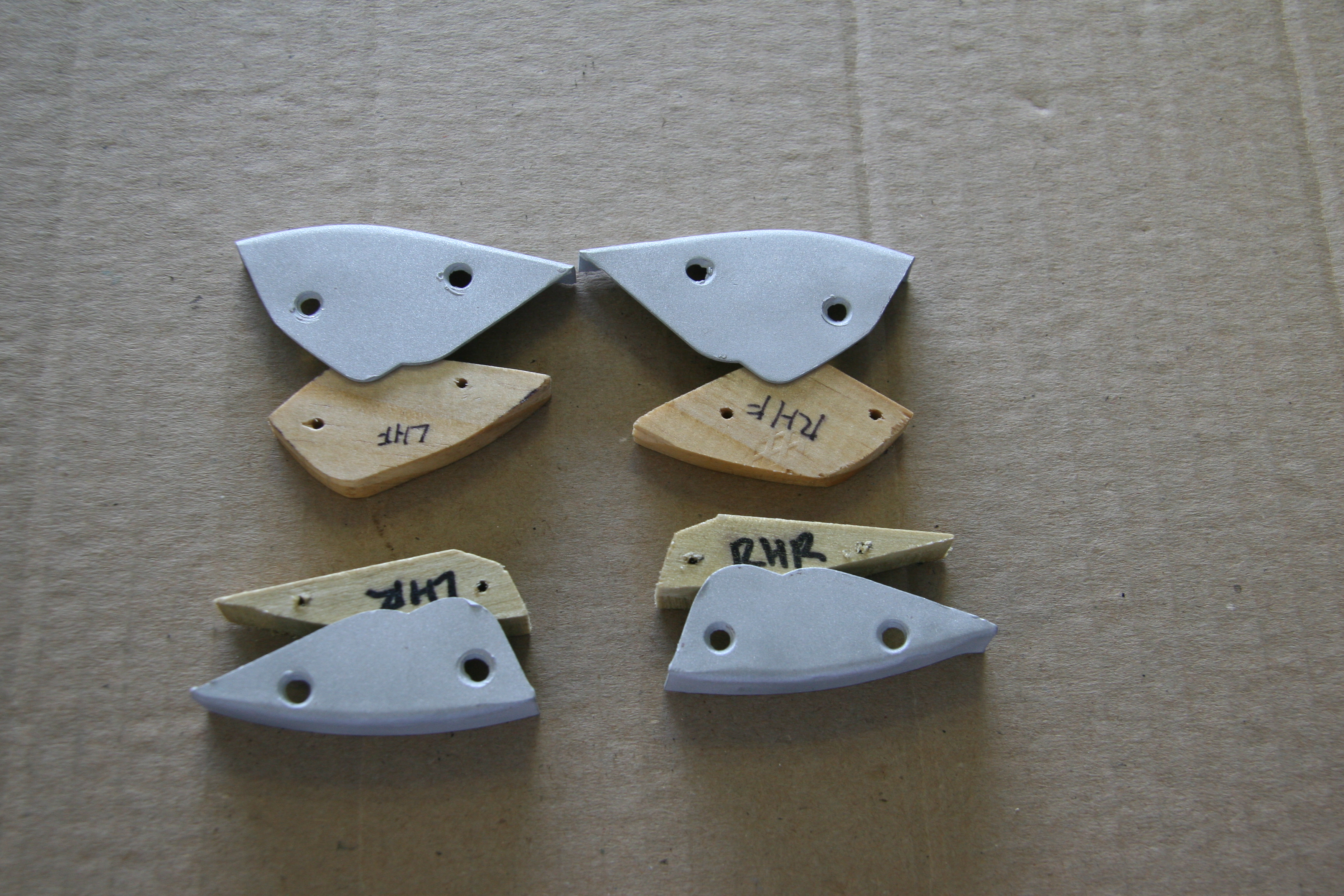
Each door has a small aluminum filler piece painted body color that is supported by a block of hardwood held together with two #4 chrome oval top wood screws in each. In my case the two rear filler pieces used 3/4″ screws while the front pieces used 1/2″ screws. Interestingly the parts manual calls for the wood packing on the front doors to be plywood and hardwood is used on the rear doors. Go figure! Modern plywood is not as wide as it was back in the sixties, so to get the proper width, I used solid wood for all four. It appears that the pieces were painted while mounted on the car, but I cannot be sure since my car has been resprayed.
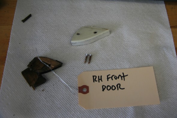
RH Front Door Filler Piece On the Shut Face Panel
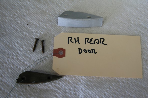
RH Rear
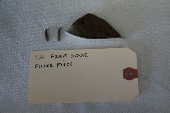
LH Front
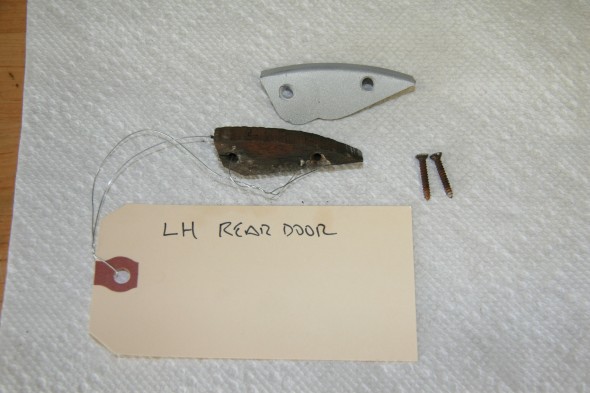
LH Rear
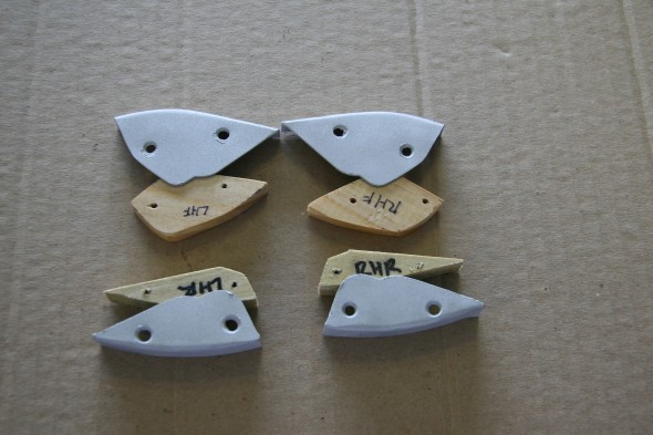
Filler Pieces, On Shut Face Panel at Waist Level of Doors with New Wood Packing
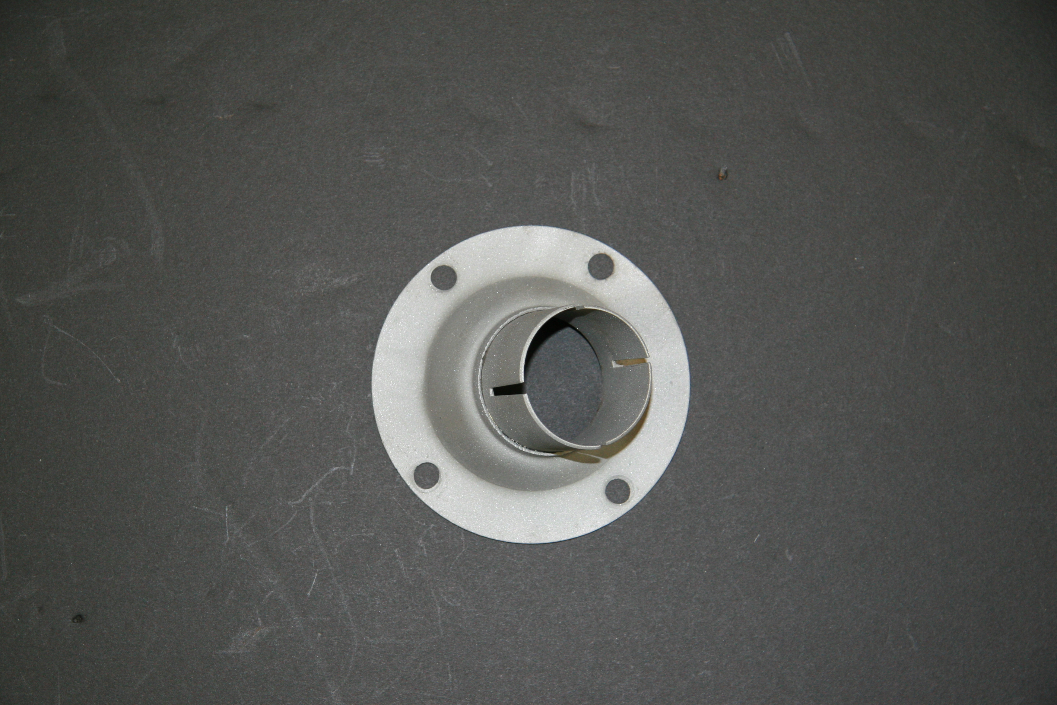
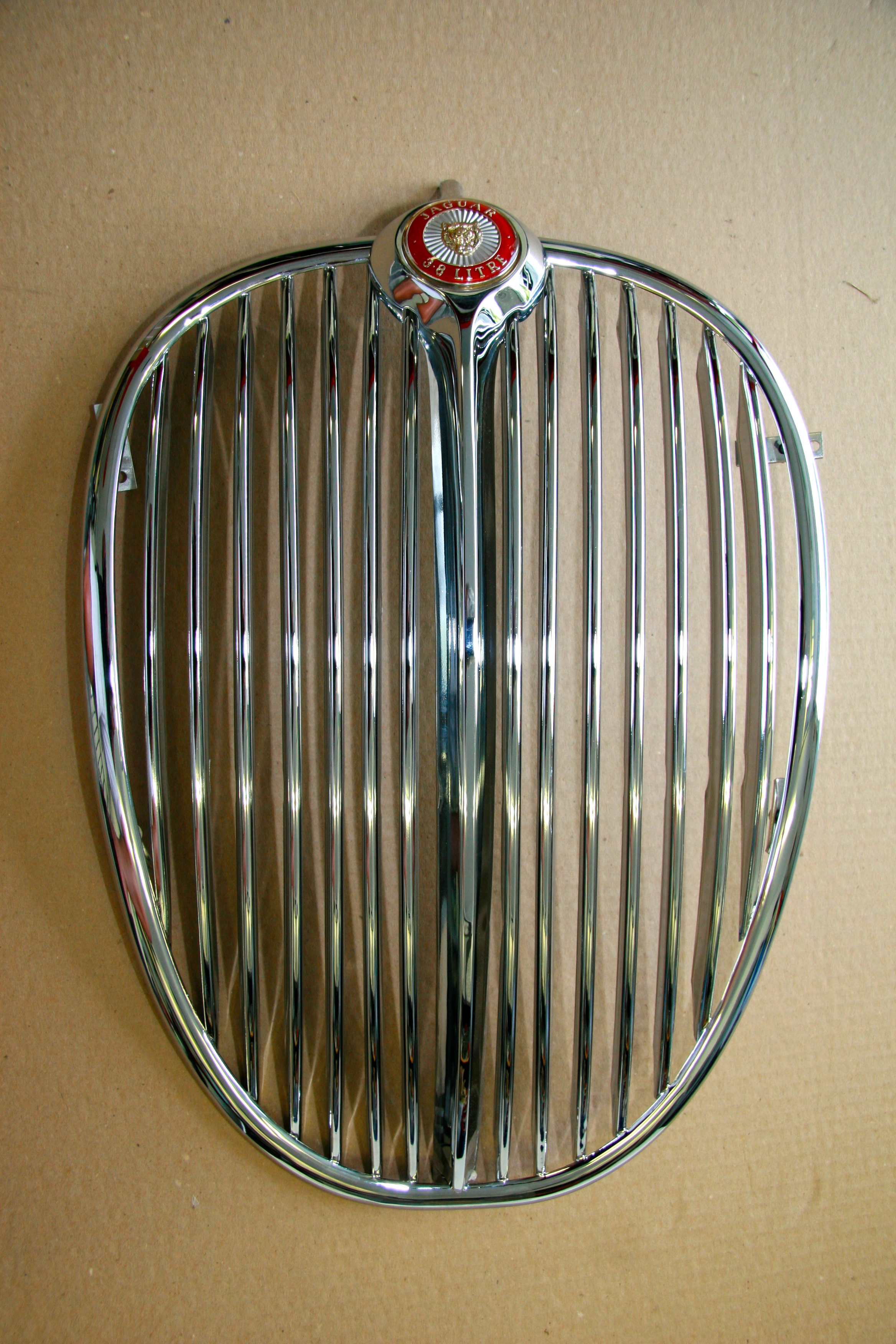
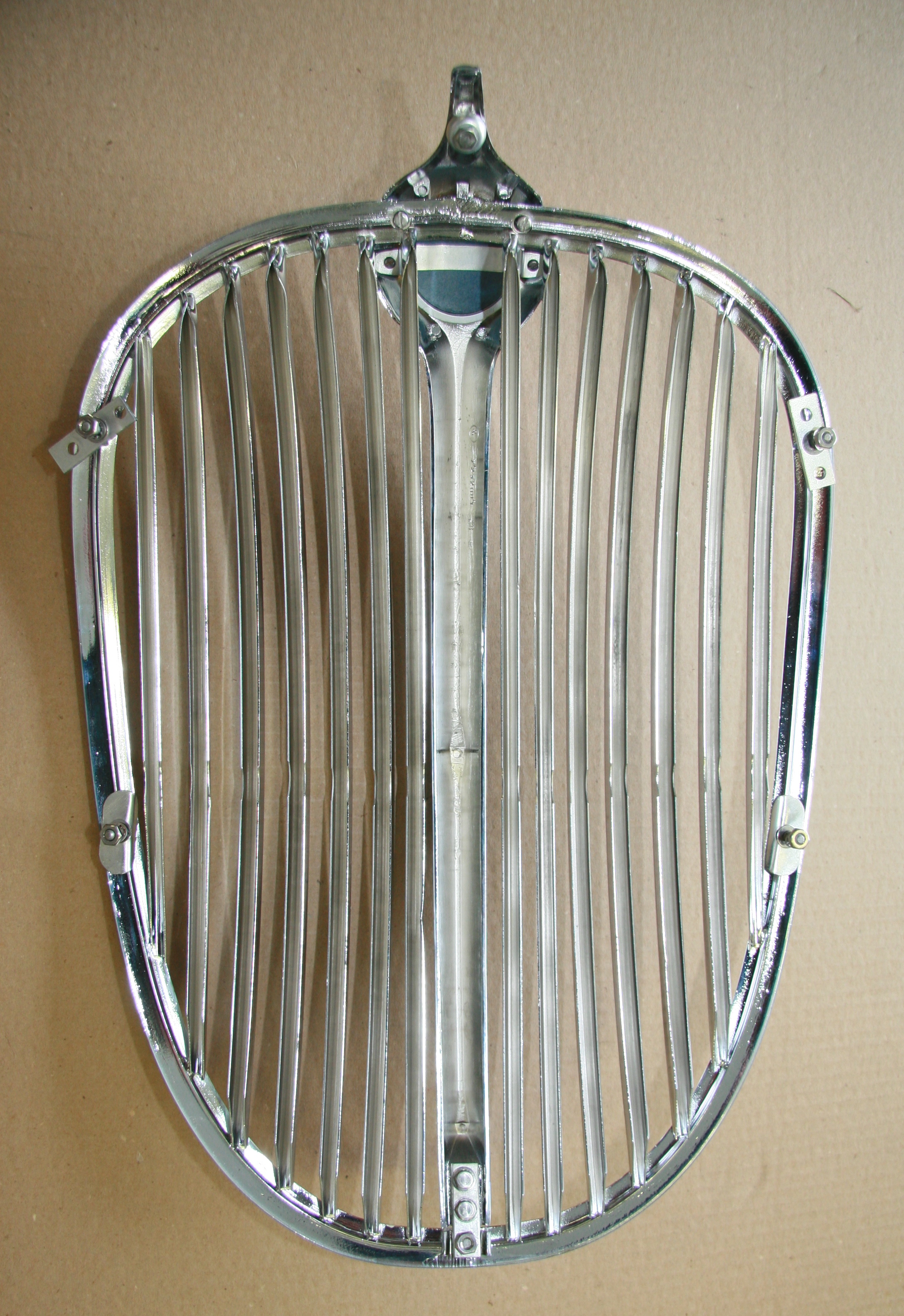
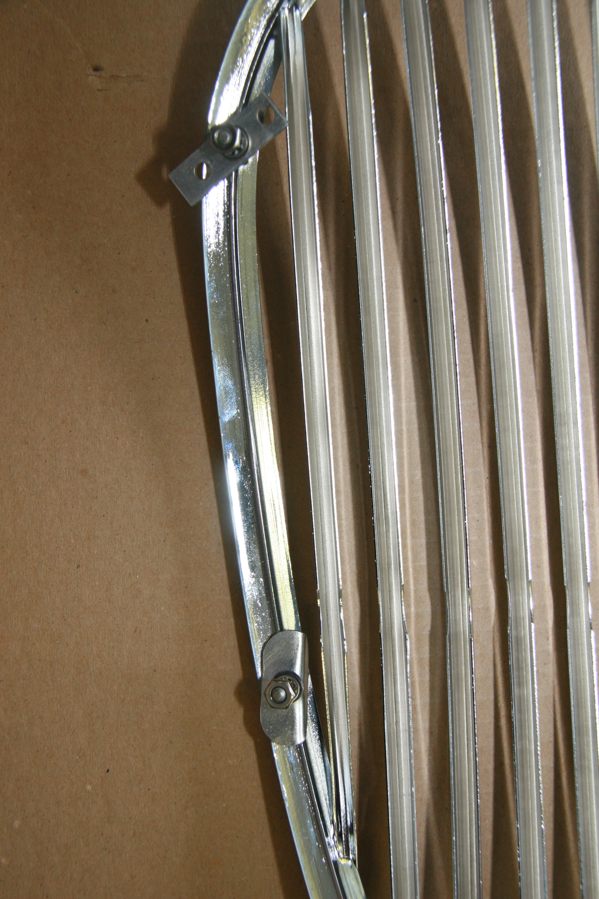
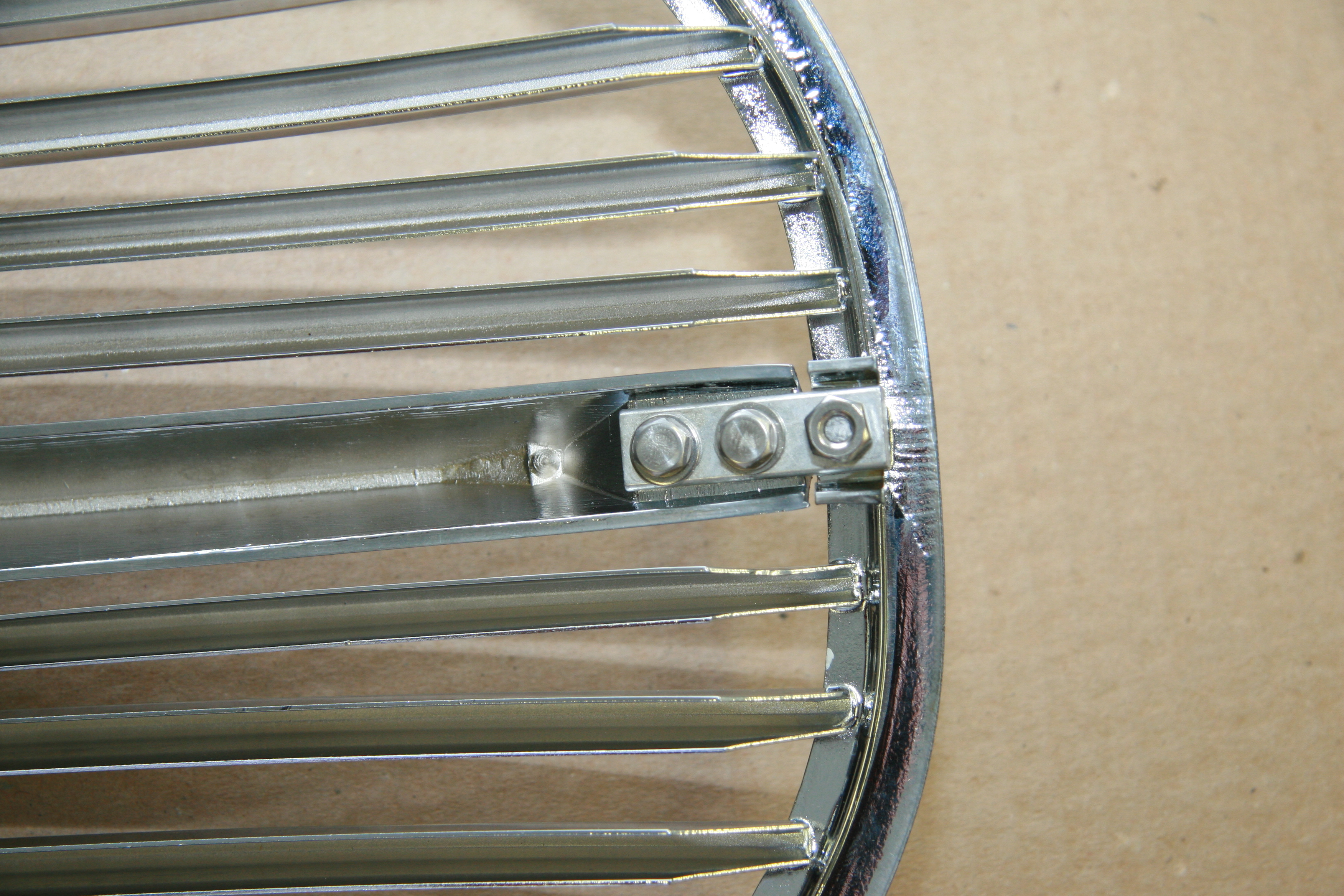
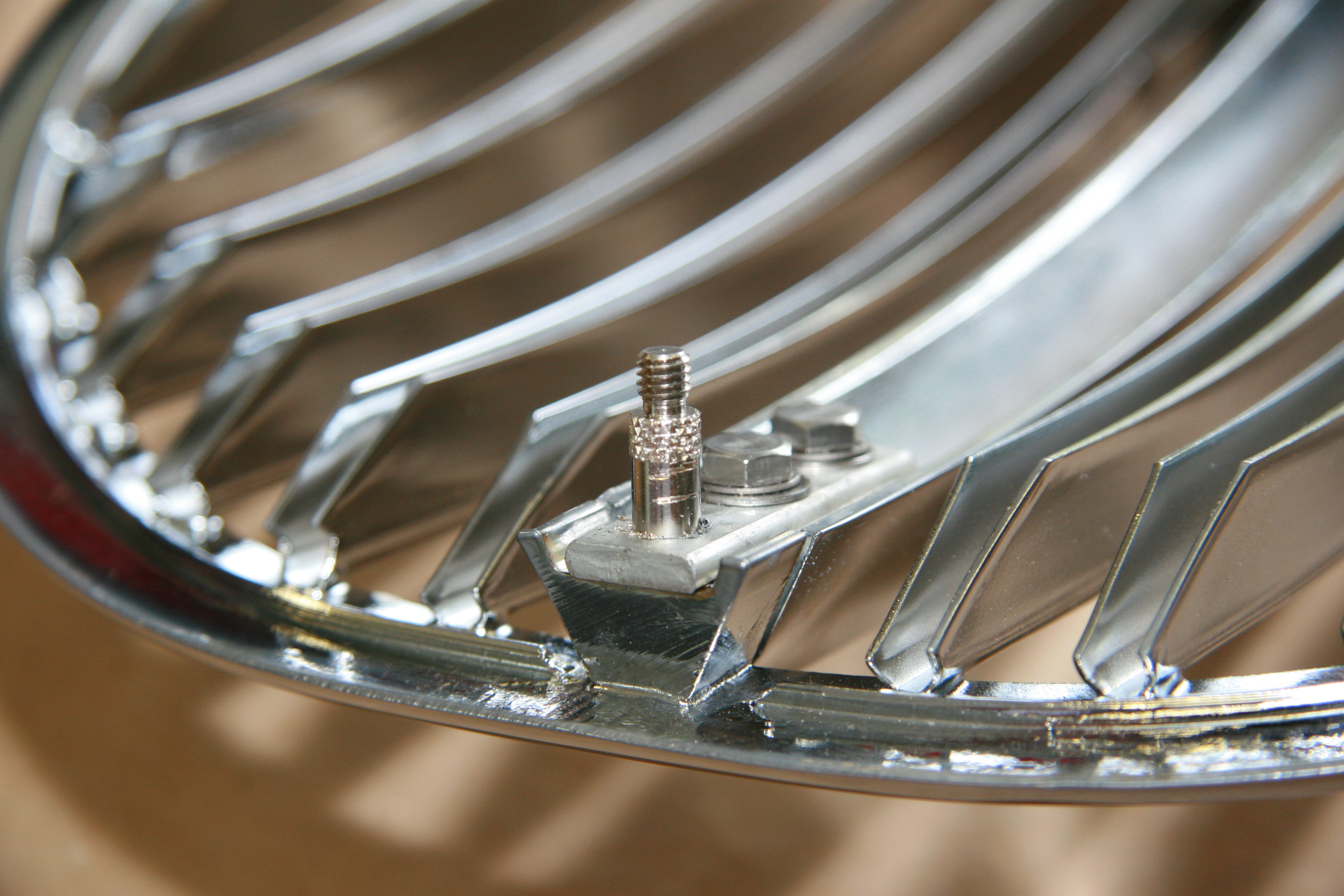
Lower Radiator Grille Fixing Plate
There is a small fixing plate at the bottom of the center vane of the radiator grille. I media blasted this piece and will have it zinc plated.
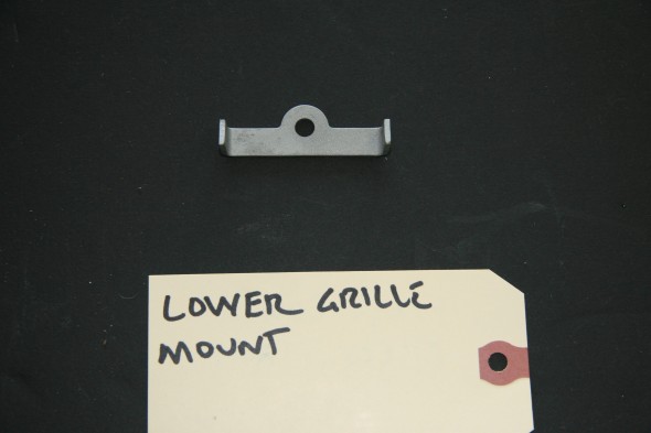
Fixing Plate at Bottom of Center Vane of the Radiator Grille
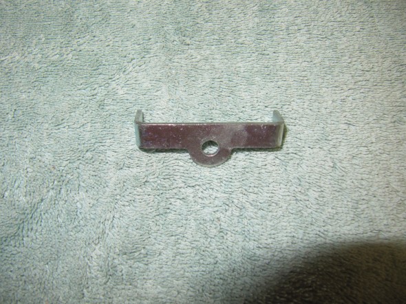
Rezinced Fixing Plate at Bottom of Center Vane of the Radiator Grille
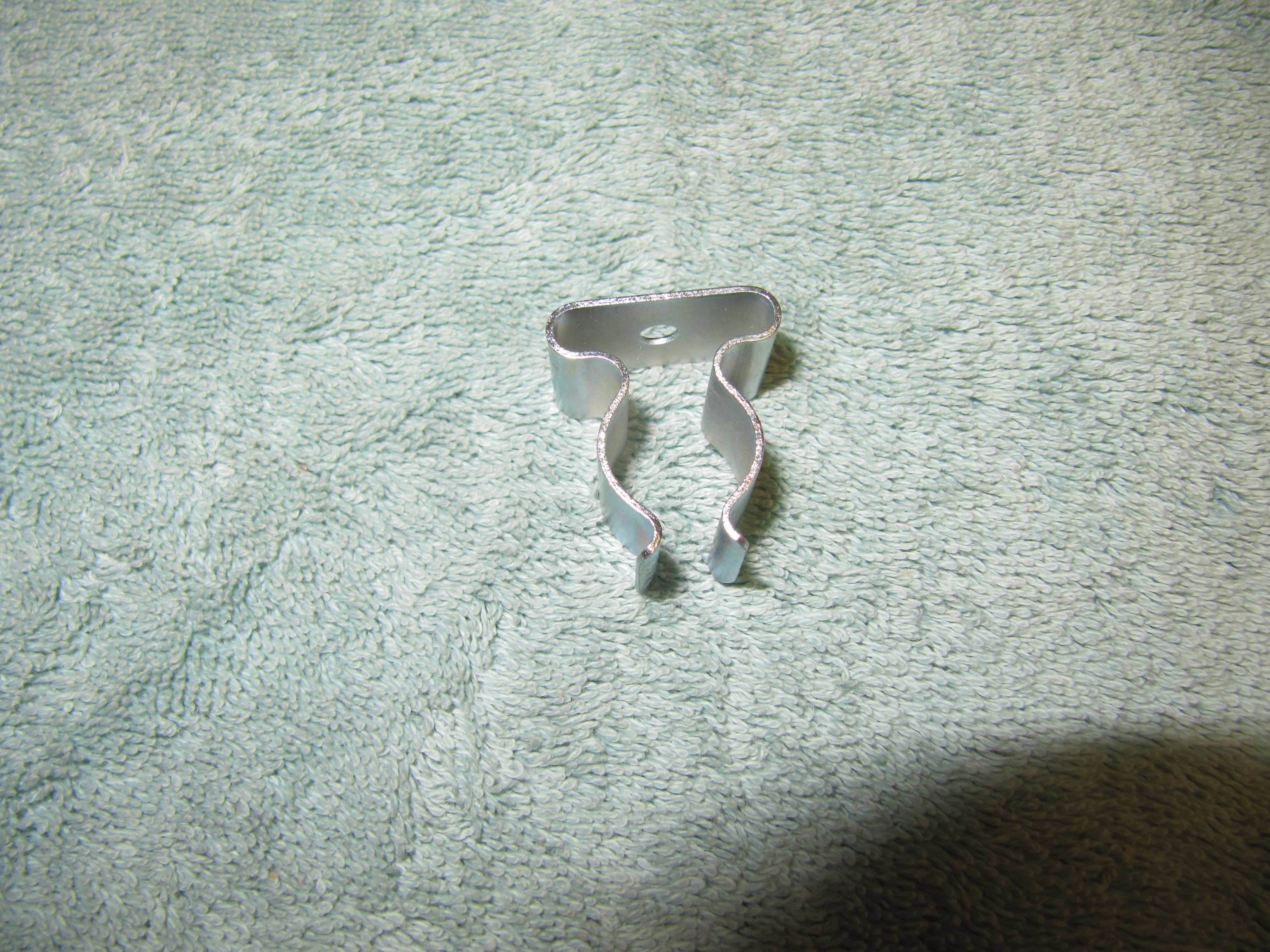
Jack Retaining Clip
This little clip helps secure the Jack in the boot of the car.
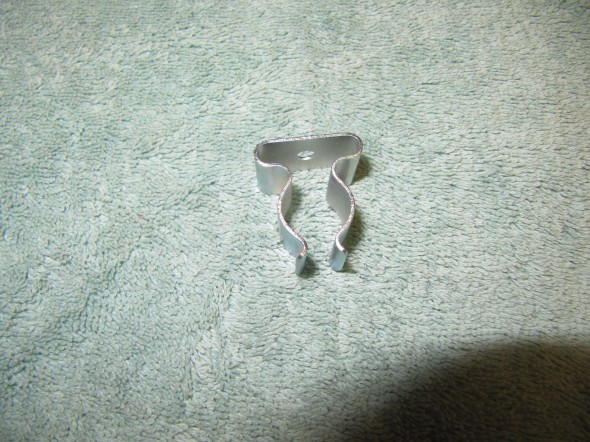
Rezinced Jack Retaining Clip
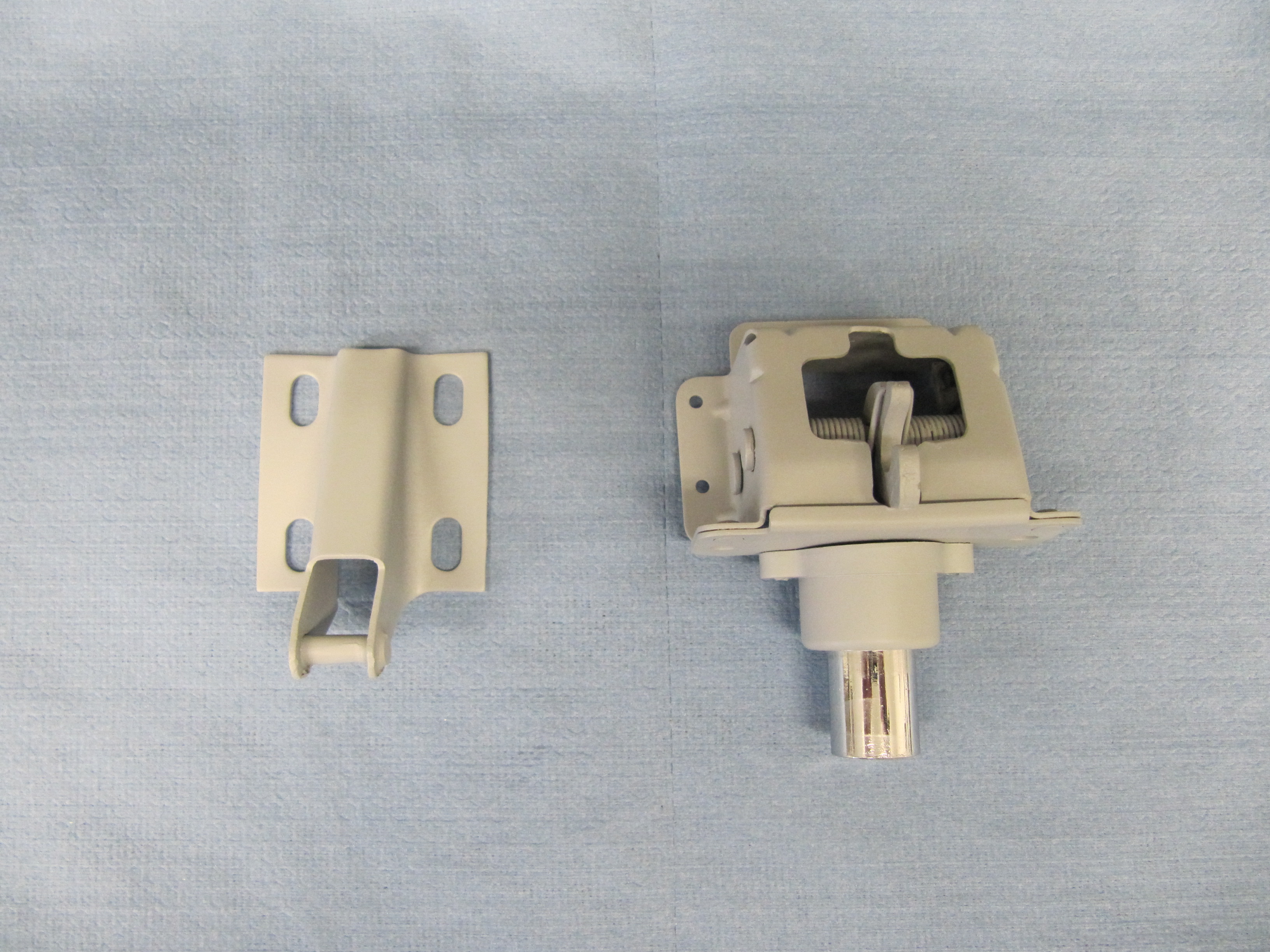
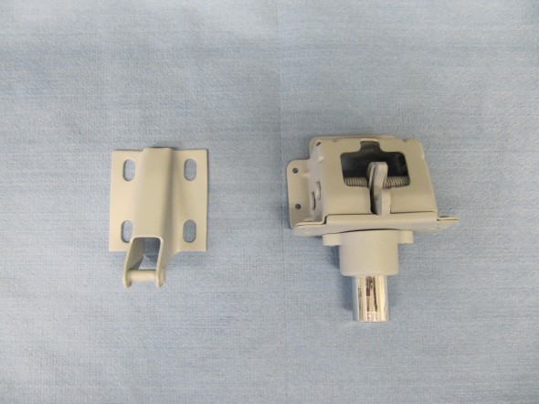
Trunk Lid Lock
The original lock assembly including the “Lock, complete, for Trunk lid”, and the “Striker Assembly for the Trunk Lid Lock” were functional and in reasonably good shape. I media blasted both of the components and primed with self-etching primer for painting body color at a later date. The lock is secured to the floor pan of the trunk with four fillister-head slotted machine screws 10 – 32 x 1/2″ into captive nuts. There is a rubber sleeve or seal that fits around the lock. It was also in reasonably good shape and will be reused. The Trunk Lid Striker is secured to the trunk lid with four 1/4″ -28 x 5/8″ hex head bolts with flat and shakeproof washers.
Trunk Lid Lock with Striker Assembly