This post covers several items added to the car as we begin to near the completion of this restoration.
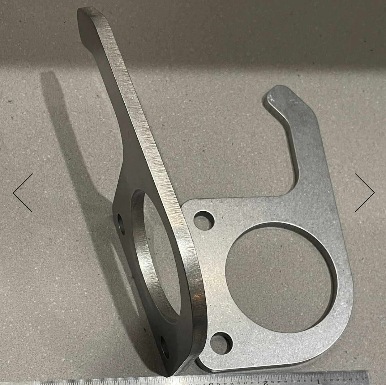
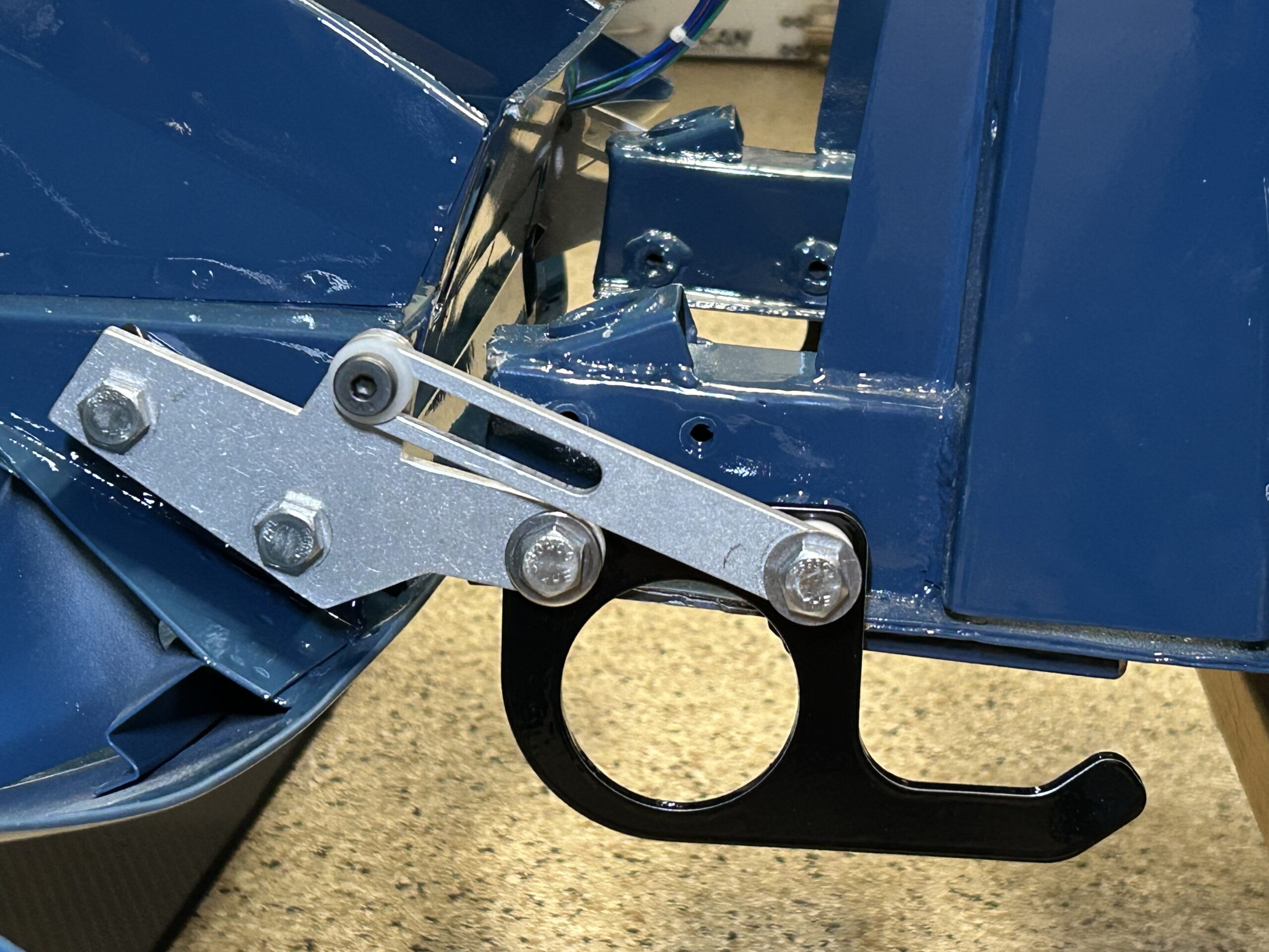
Rear Tie down brackets (tow hooks)
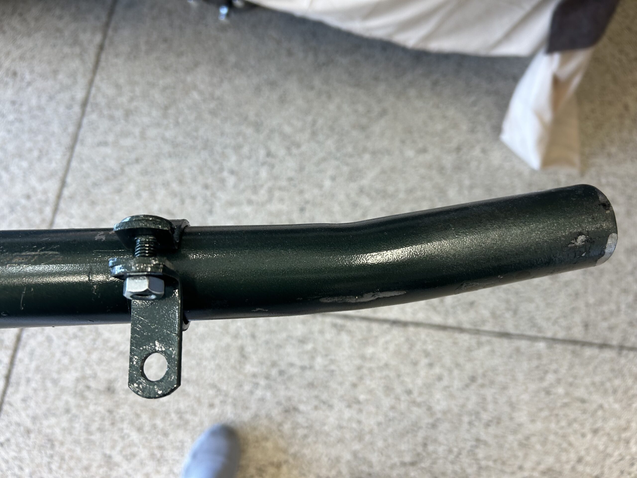
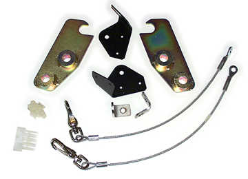
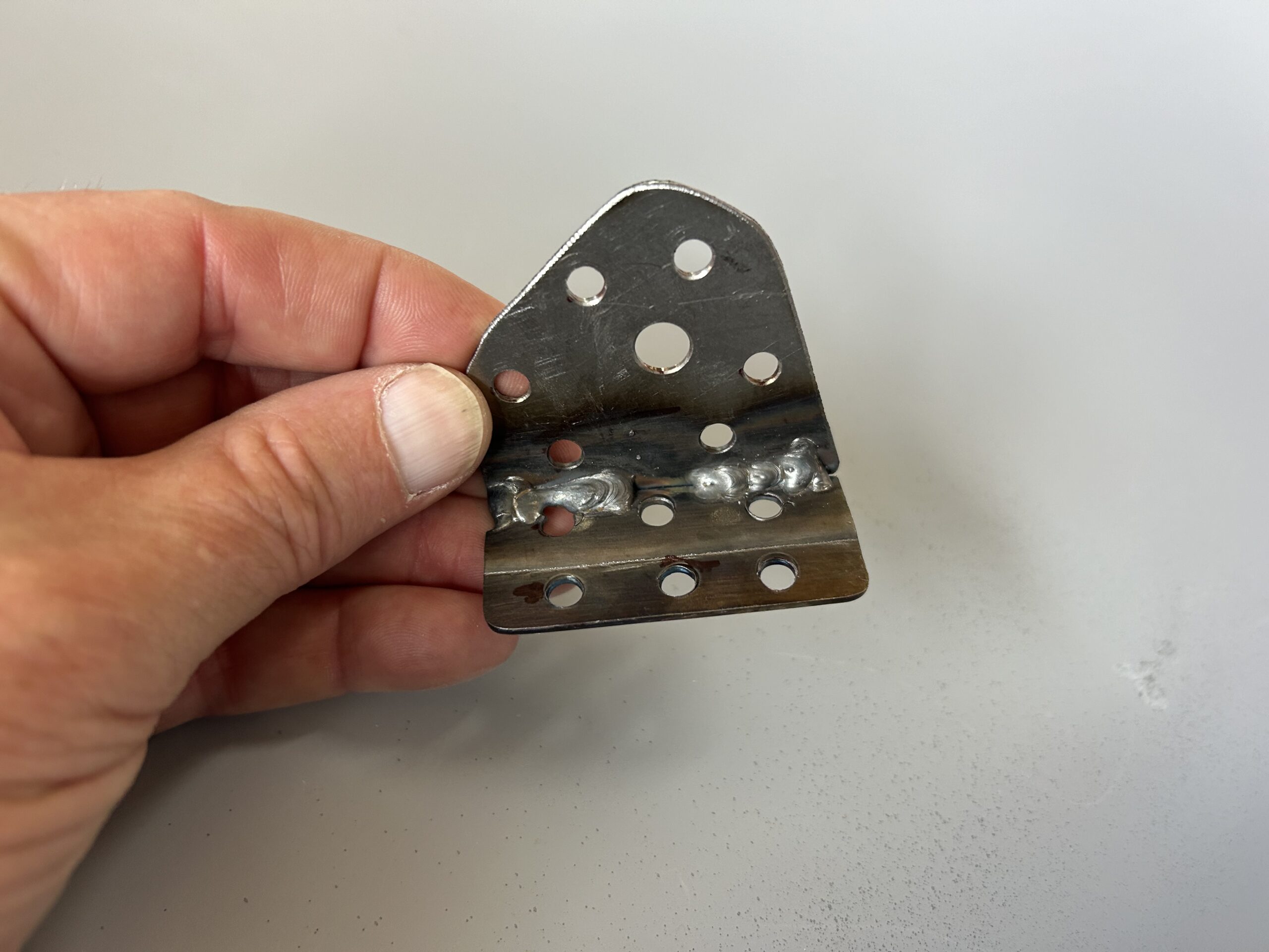
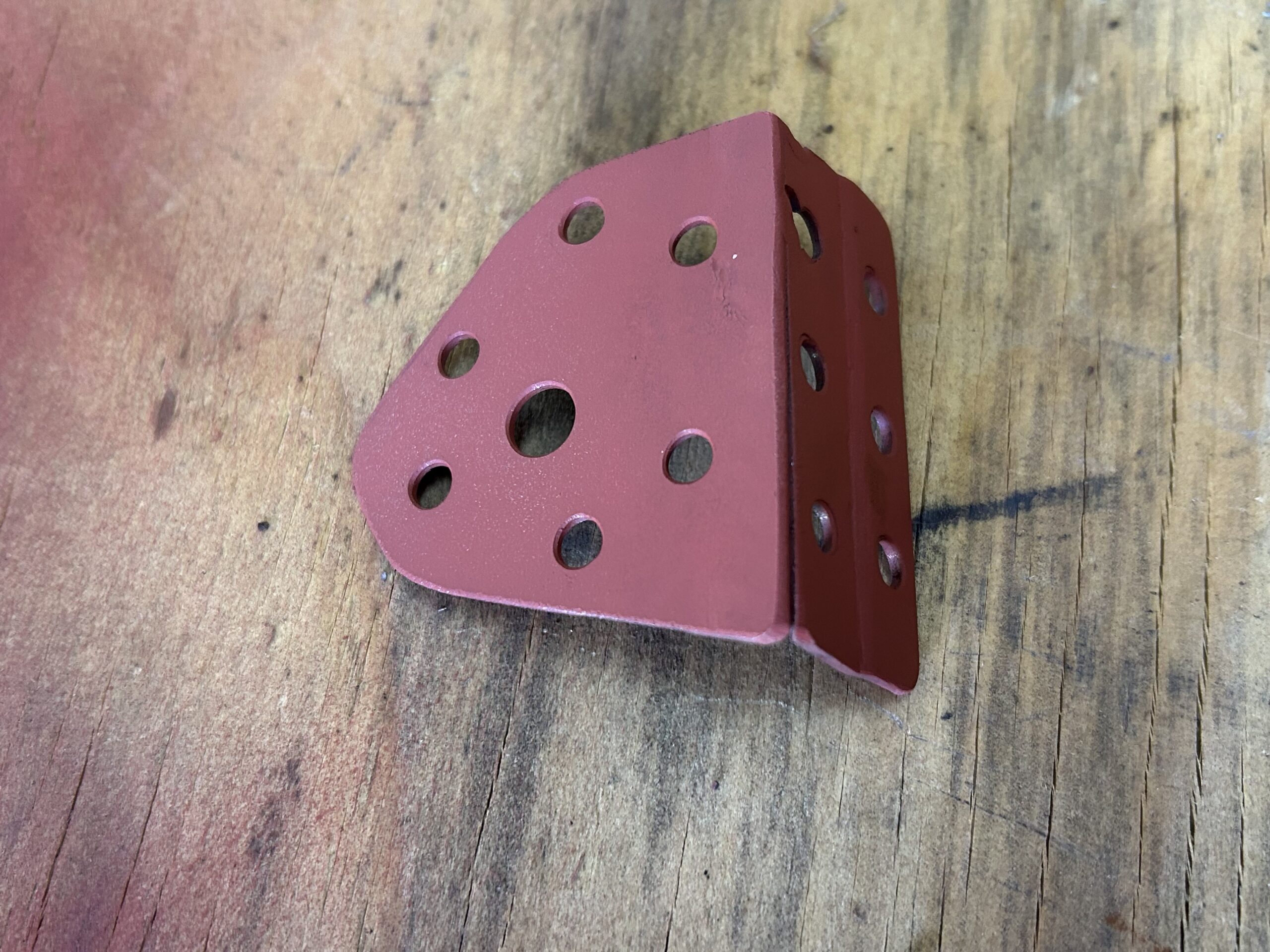
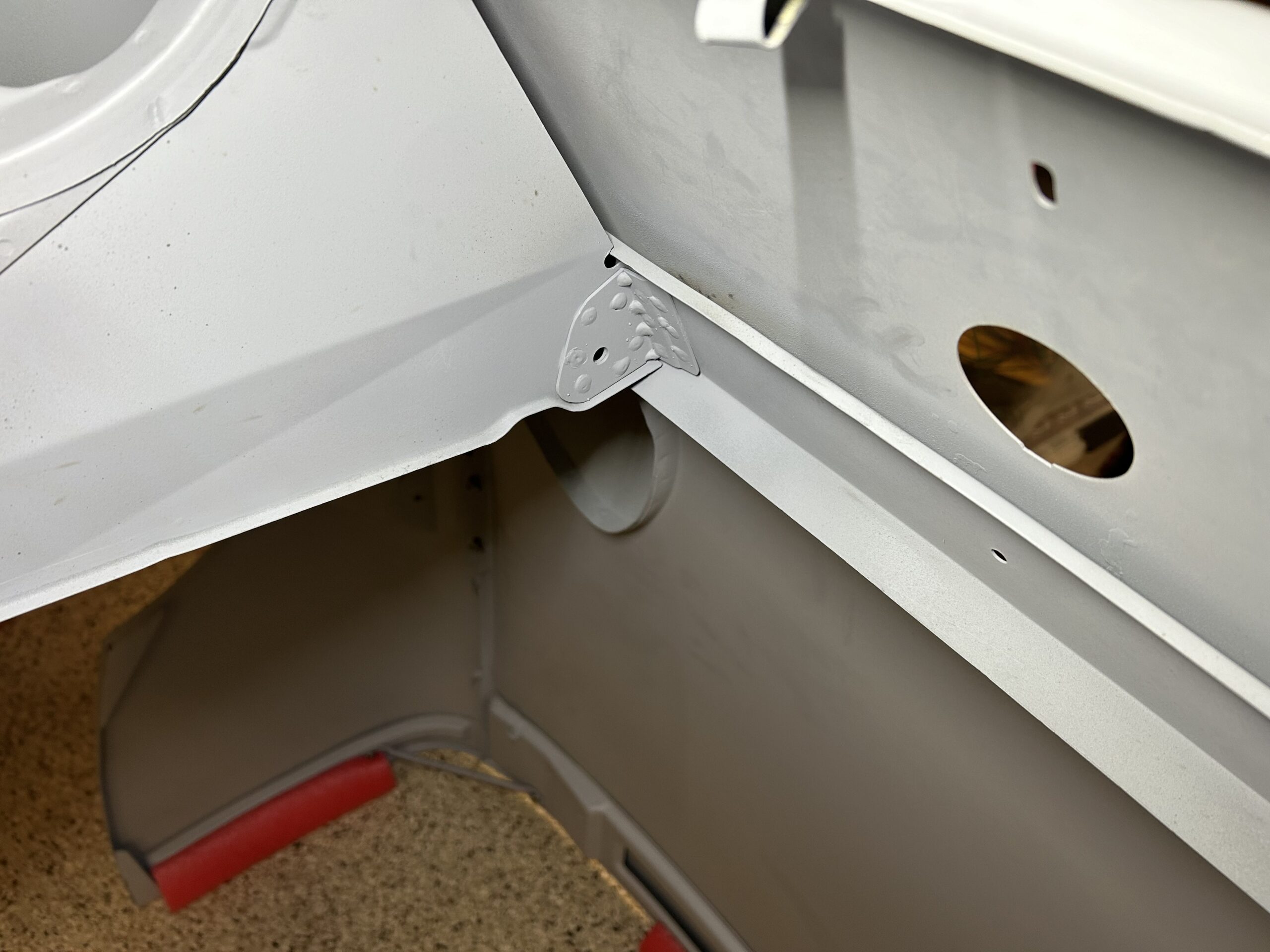
In an earlier post the front tie down brackets, or tow hooks, were mounted to the car. We also purchased rear tie down brackets or tow hooks from Q1 Classic Engineering. These are heavy duty and very nicely made. We painted them black with POR 15 and easily installed them.
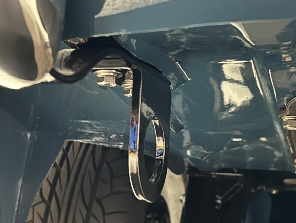
Rear Tie Down Brackets
Battery management quick connect cables
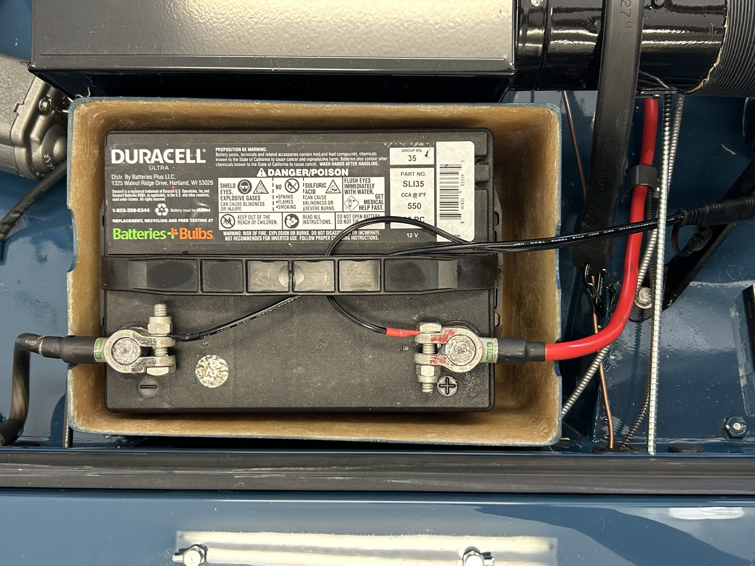
We then added some wiring to the battery so that we would have a quick connect system for the battery management charger. This is particularly useful given that we have a cover on the battery.
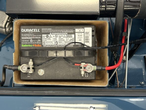
Battery Management Quick Connect Wiring
Horns revisited
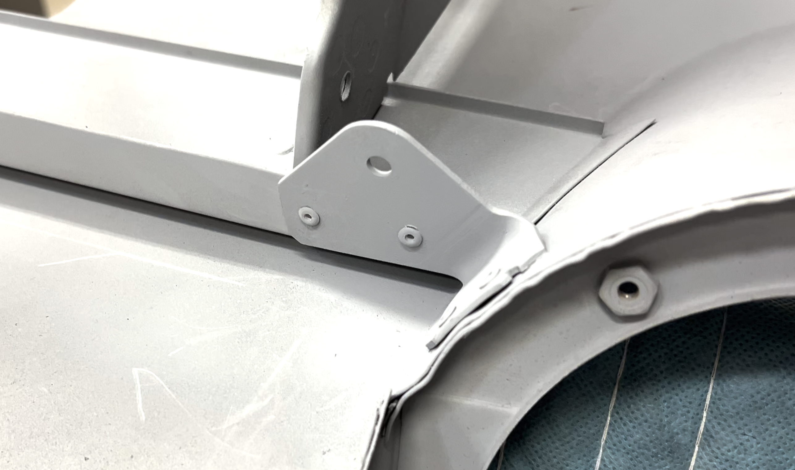
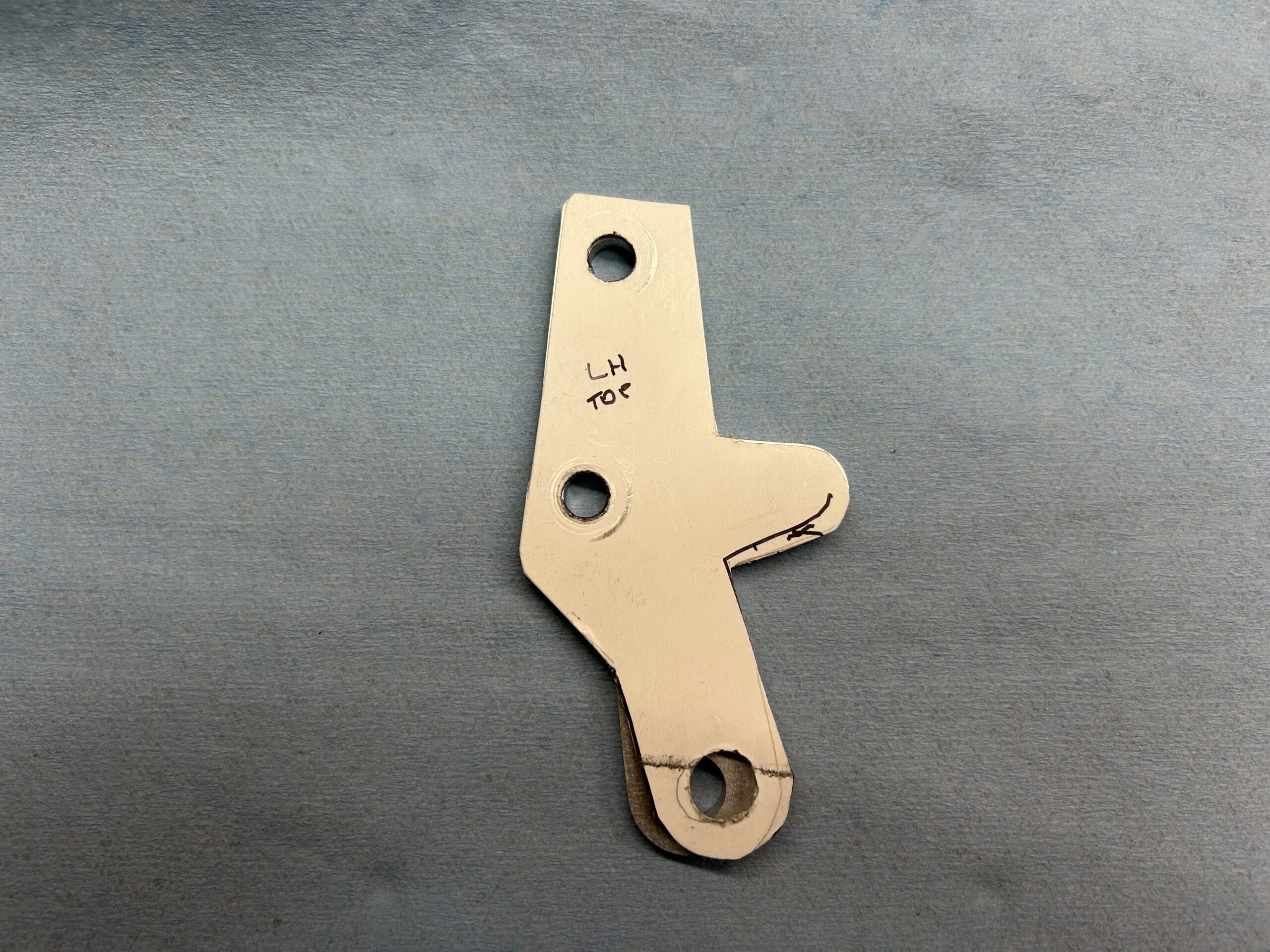
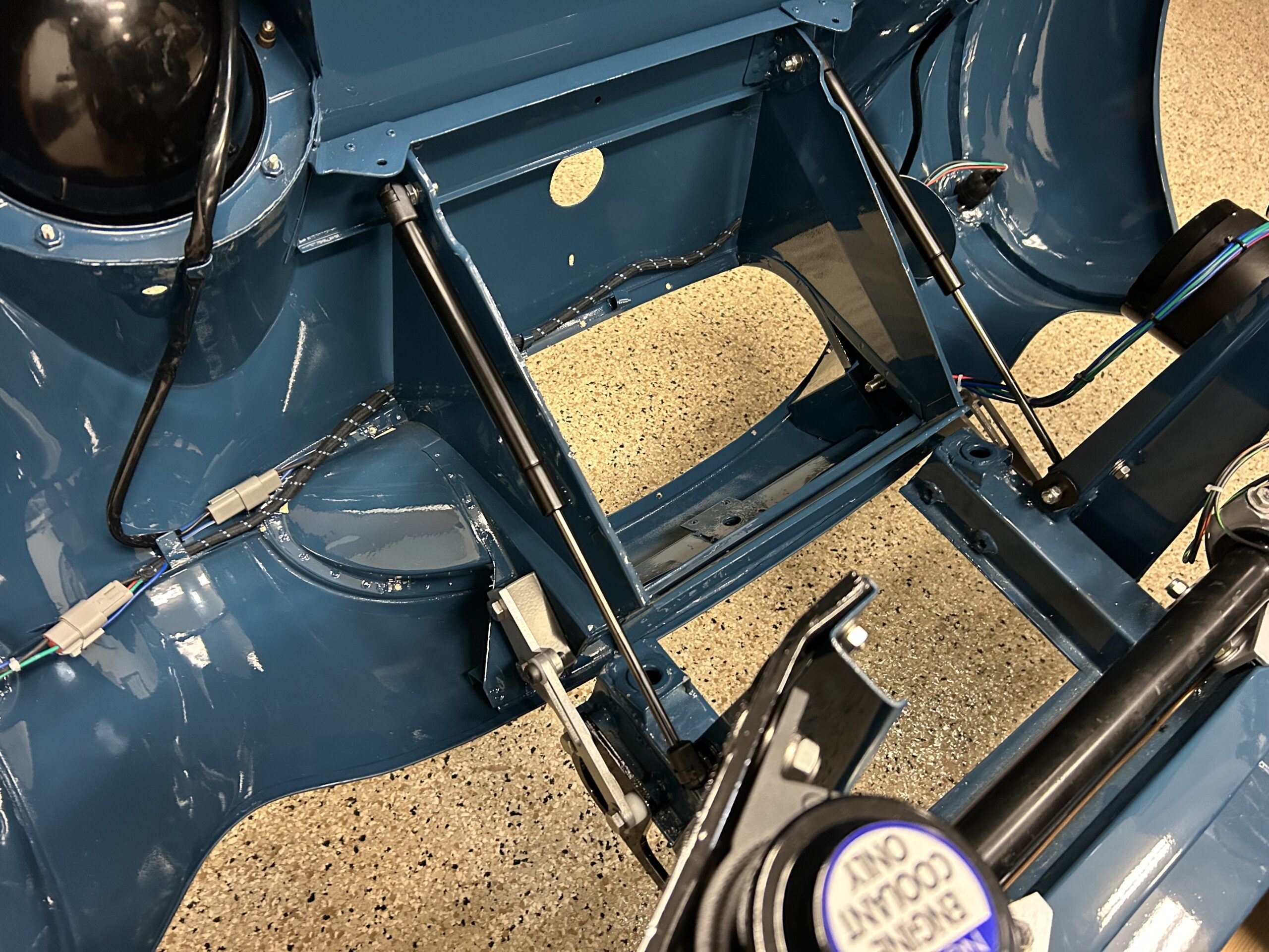
We discovered, with the installation of the bonnet gas struts, that the operation of the RH strut hit the interior horn. So, we decided to forgo the second horn and just use one. The single horn, by the way, seemed plenty loud.
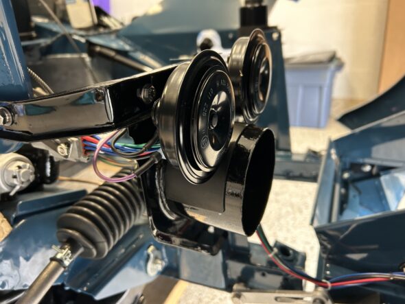
Dropping the Interior Horn
Painting the exhaust
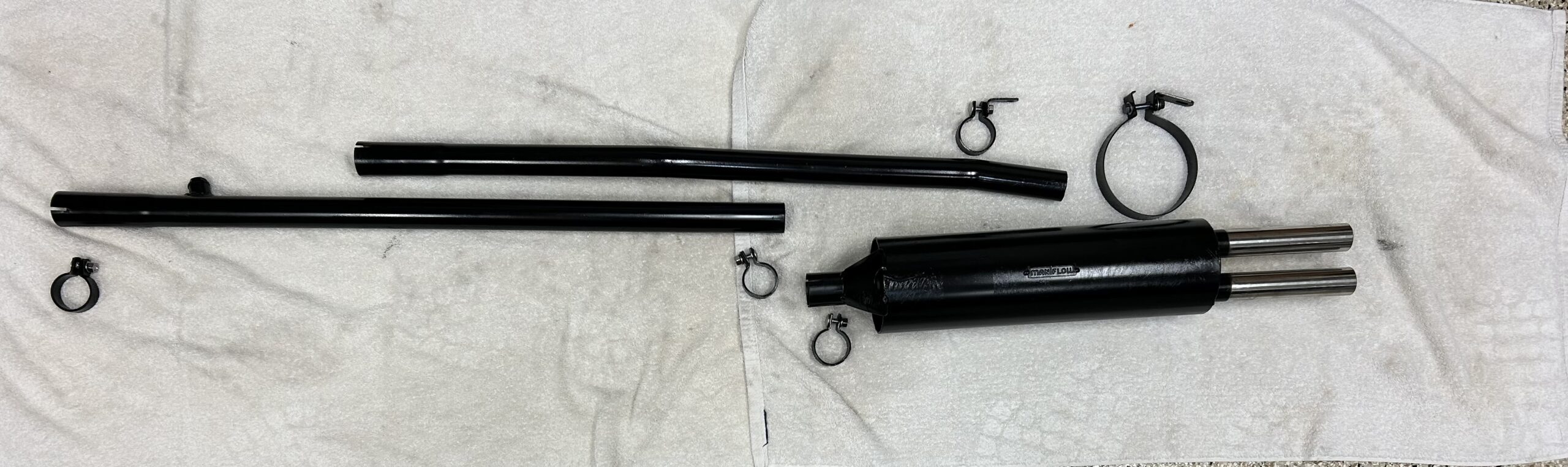
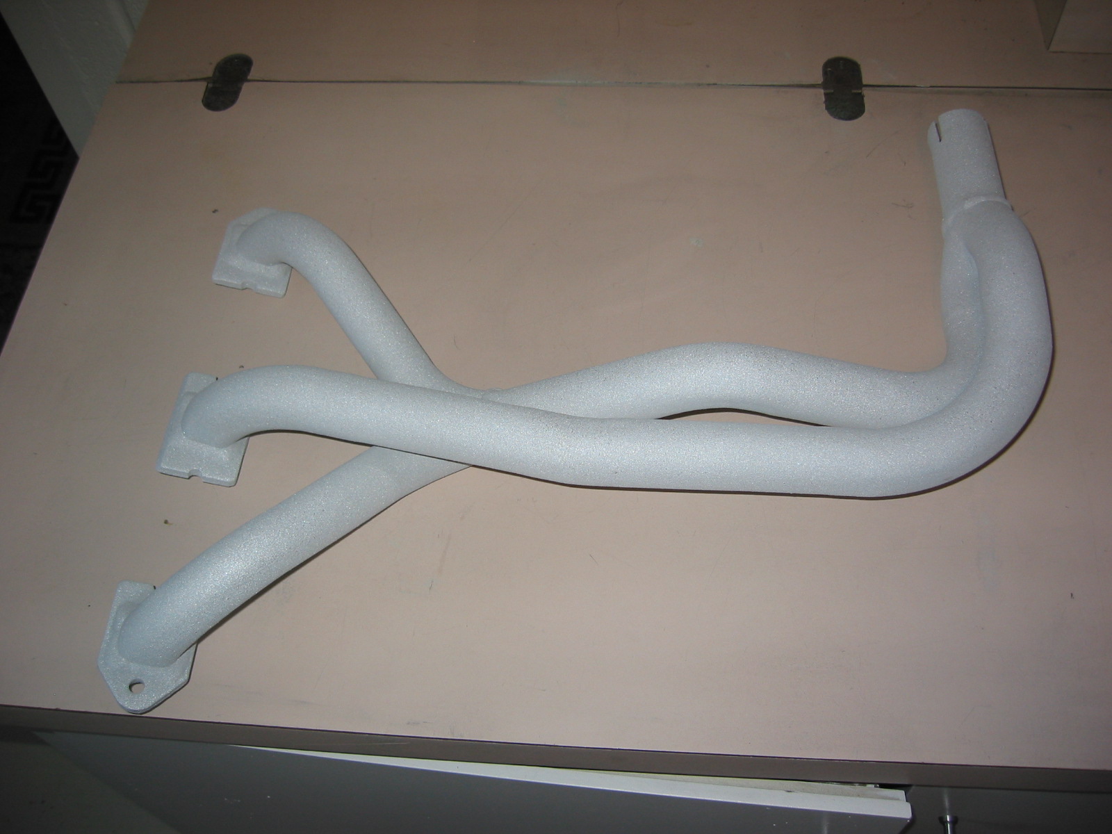
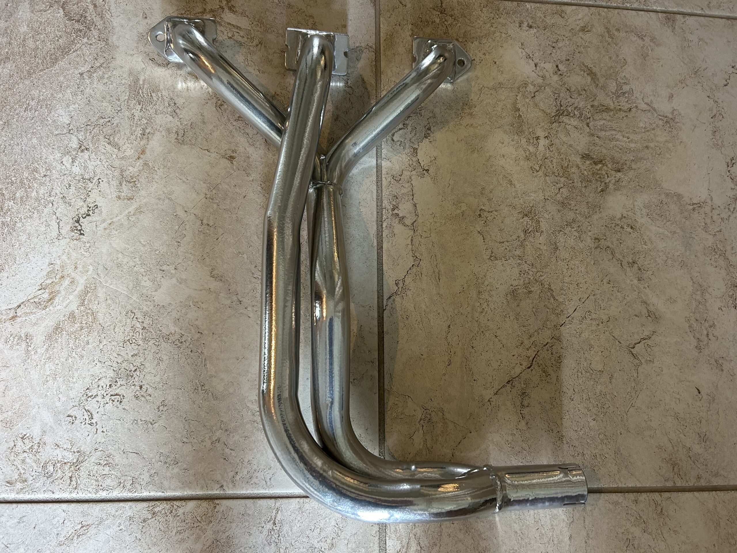
We are not ready to install the exhaust but this was a good time to go ahead and paint it. It came from Maniflow with their familiar metallic green paint. We simply roughed it up with a little sand paper and sprayed it with Rustoleum black BBQ high temperature paint.

Maniflow Metallic Green
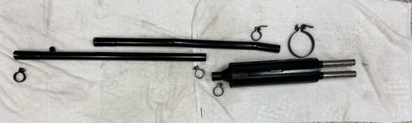
Exhaust painted high temperature semi-gloss black
Installing the anti-sway bar
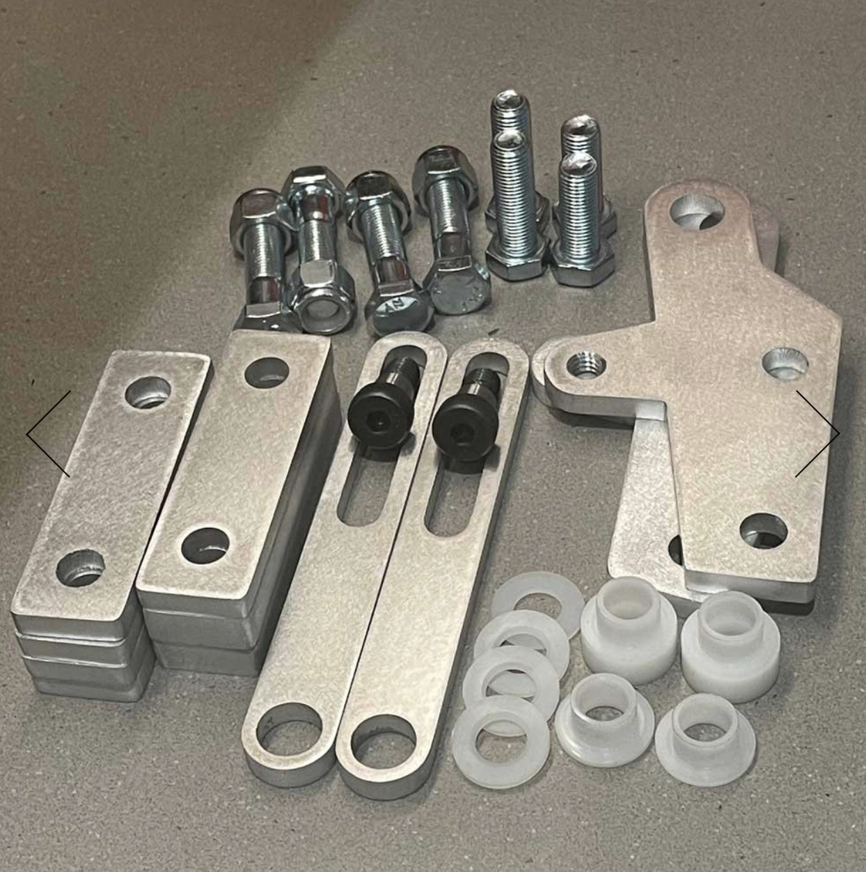
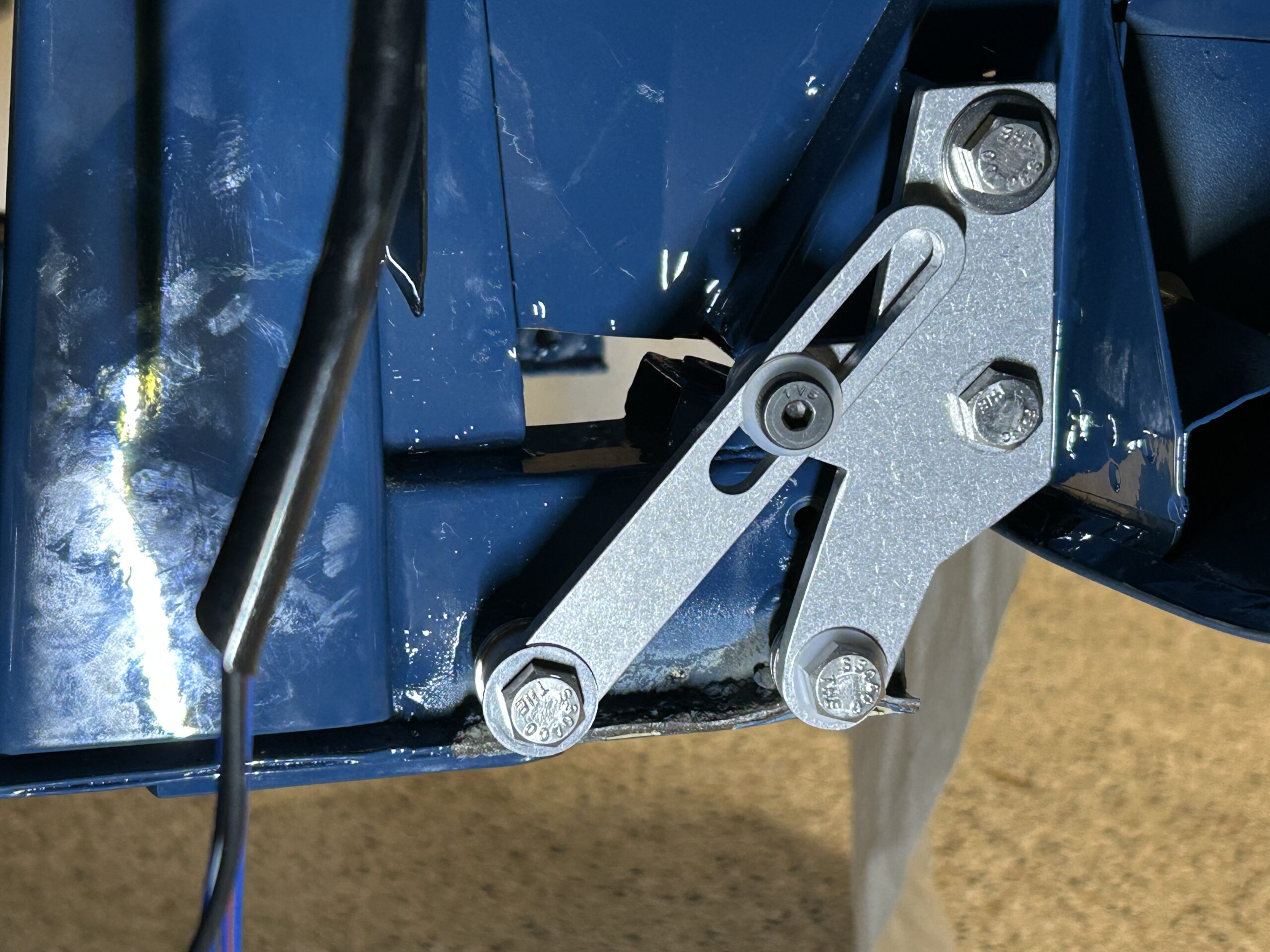
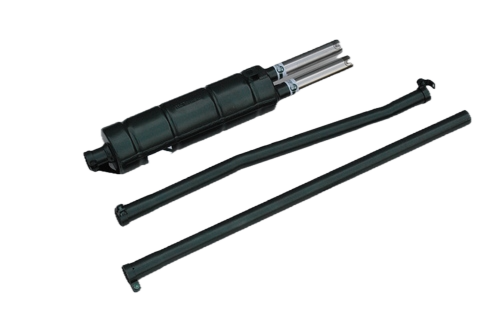
We then installed the anti-sway bar that we purchased from BugeyeGuys.com. We had previously painted the components so this turned out to be a quick job.
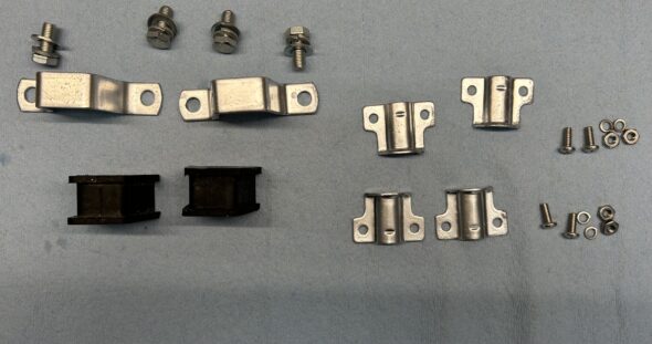
Anti-sway bar bits
Installing the motor mounts
The motor mounts were then installed. However, when we are ready to install the motor we will remove the RH motor mount and fix it to the motor. The LH mount will remain in the car because it is easier to leave it due to the steering column.
Heater control cable
We then connected the heater flap control cable that comes through the firewall from the heater switch to the bracket on the heater blower.
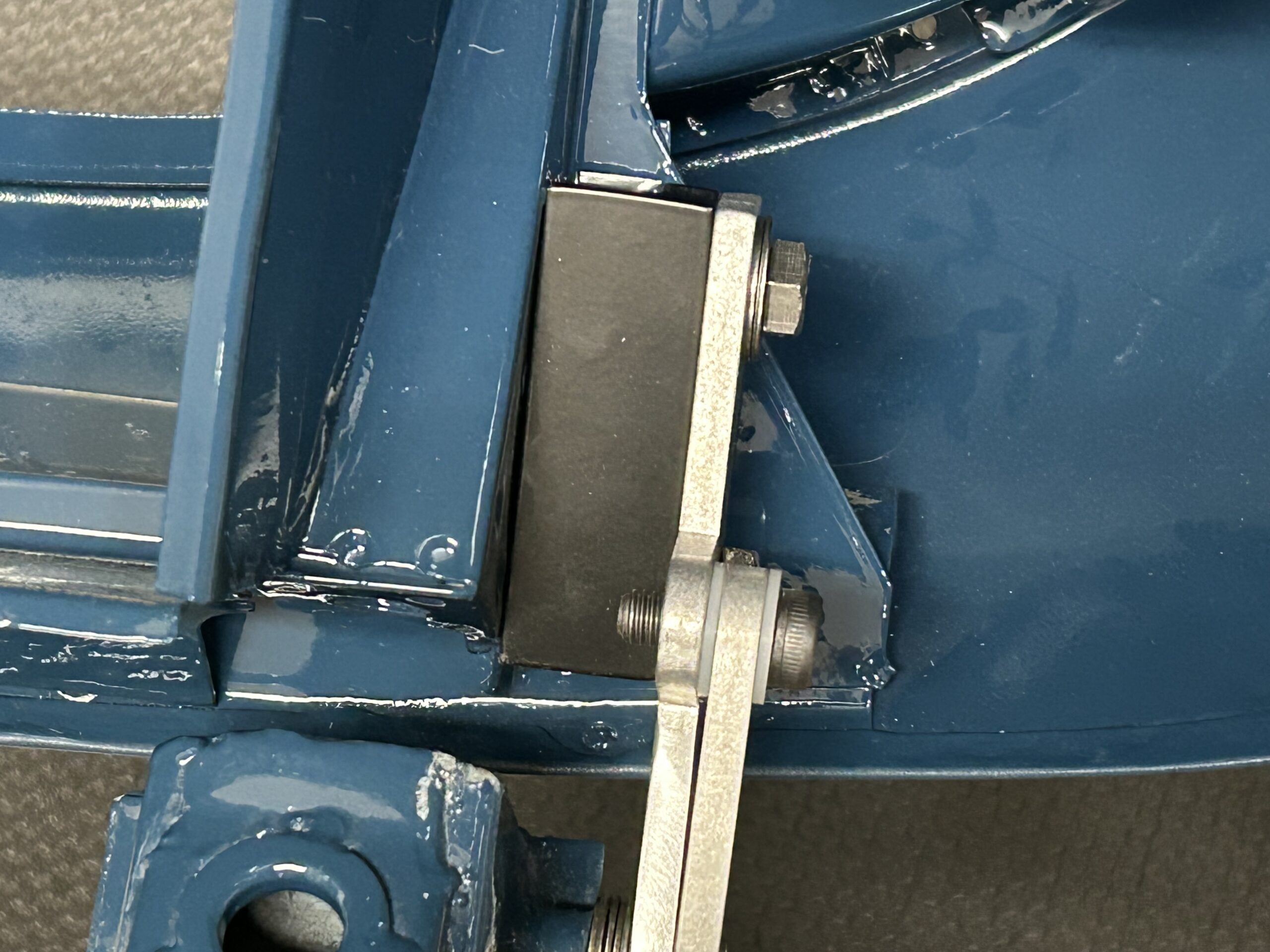
Machining a starter cable connector
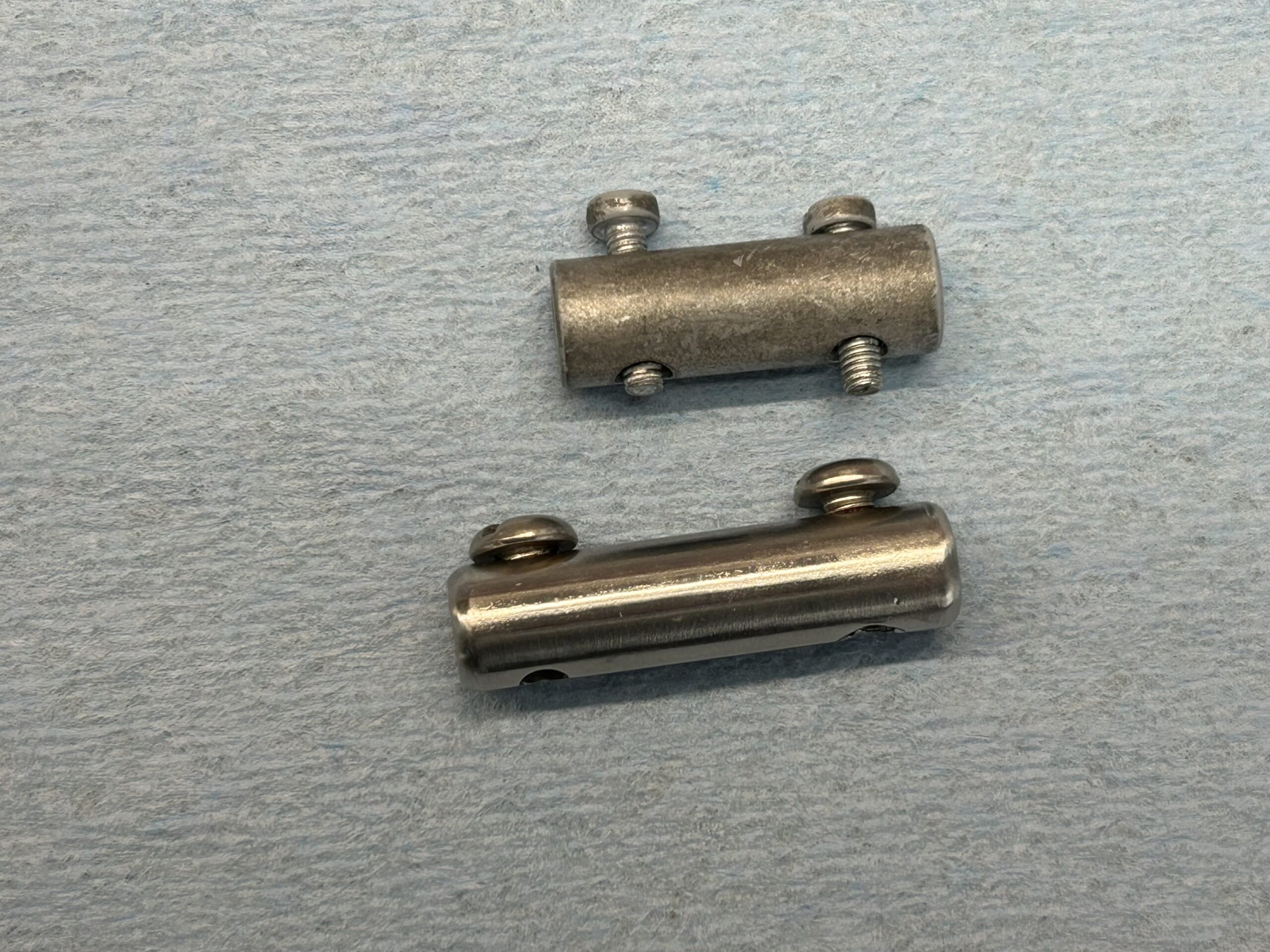
For some reason the standard connector that joins the starter cable and the starter switch is too short to do the job on the car. We know that the battery tray was replaced and perhaps the starter switch mounting bracket that is attached to the tray was slightly off? At any rate we solved this problem by machining a new connector made from a 3/8″ stainless steel bolt. Our friend Randy Forbes did the mill work for us. Thank you Randy! The new piece – almost identical but about a 1/4″ longer worked beautifully.
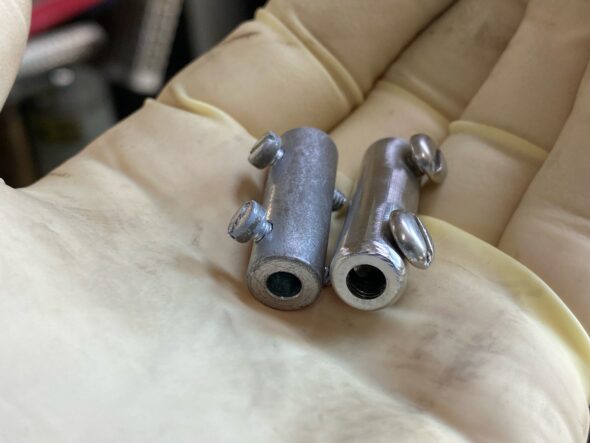
A new stainless starter cable connector

The new and the old
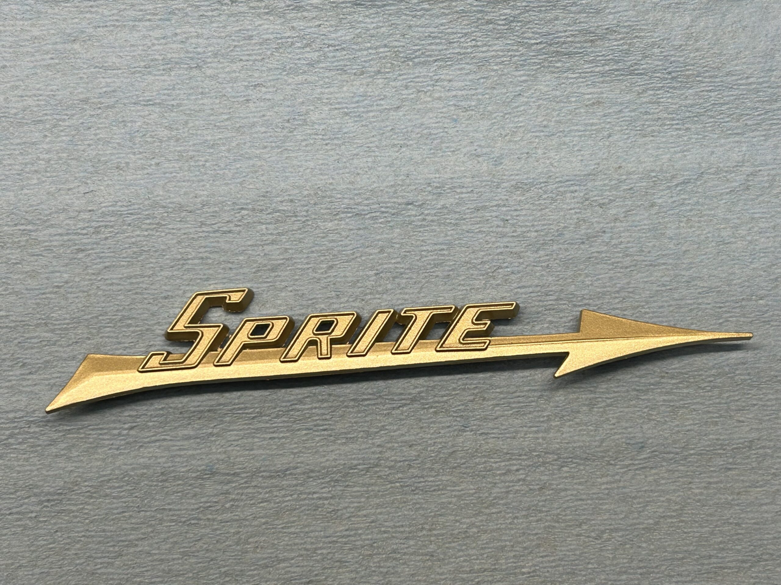
Repainting the Sprite Flash
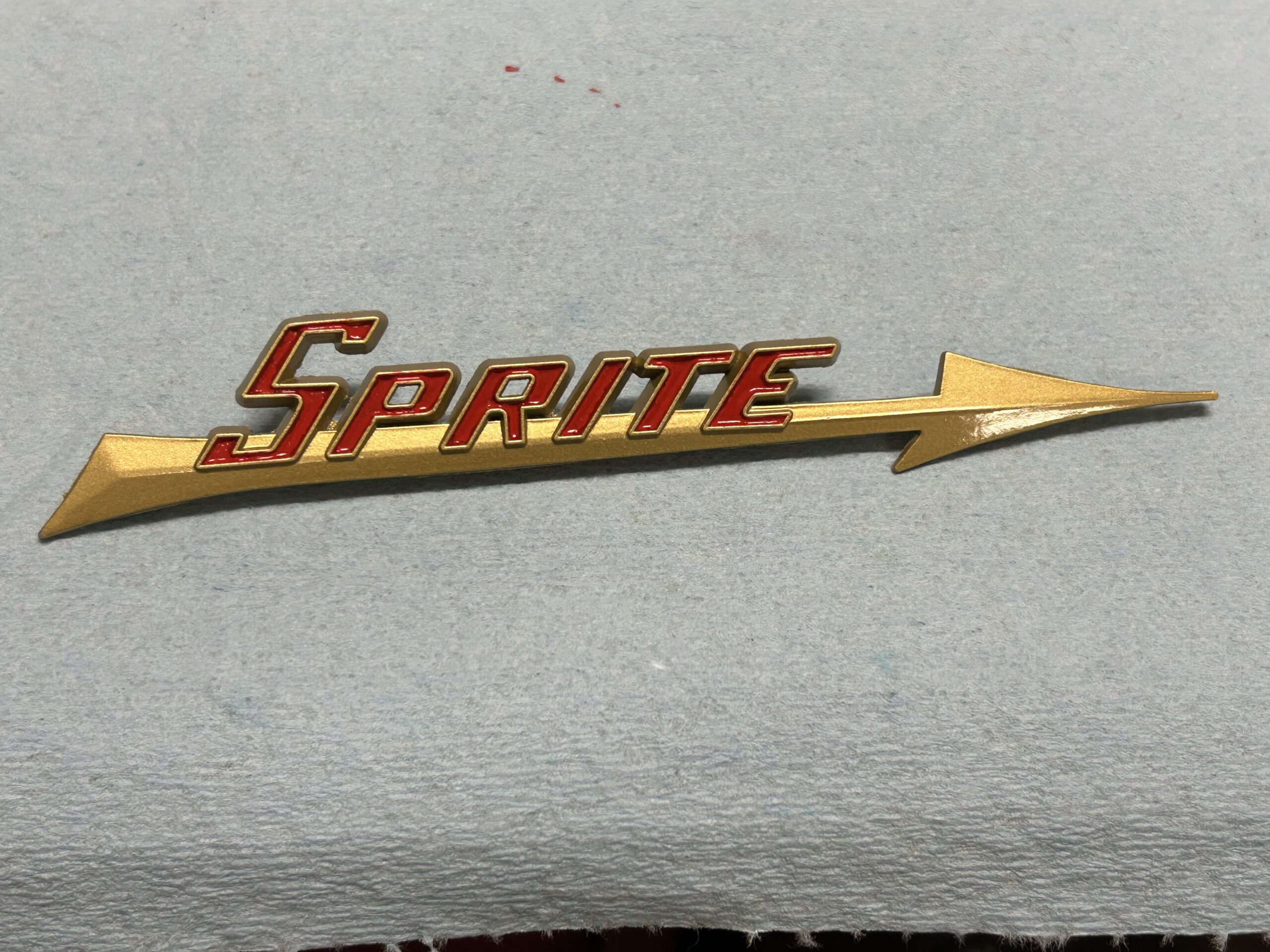
The flash emblem or badge as mounted on the rear deck of the car was gold with red lettering. Unfortunately, the replicas of the badge available from the usual suppliers is copper in color with the red lettering. So, we stripped the paint from the badge and then repainted the badge with Rustoleum metallic gold spray paint, followed by painting the red letters and finally coating the badge with Rustoleum Krystal Clear. We were pleased with the results. We are going to mount the badge later and will be using a 3M adhesive rather than mounting it through holes in the car.

The gold paint first
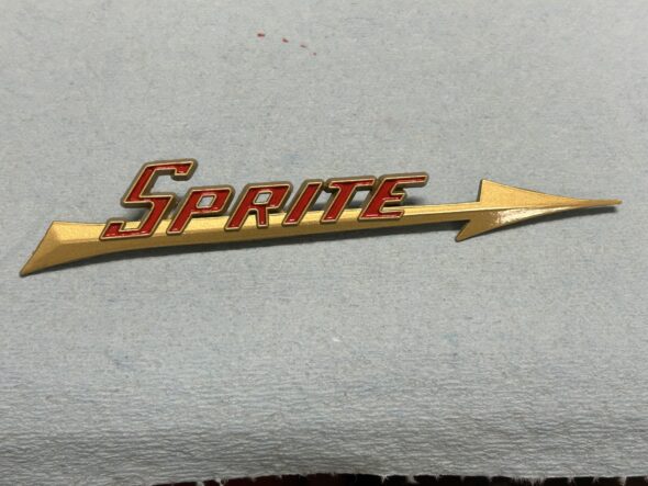
Followed by Red in the letters and Clear
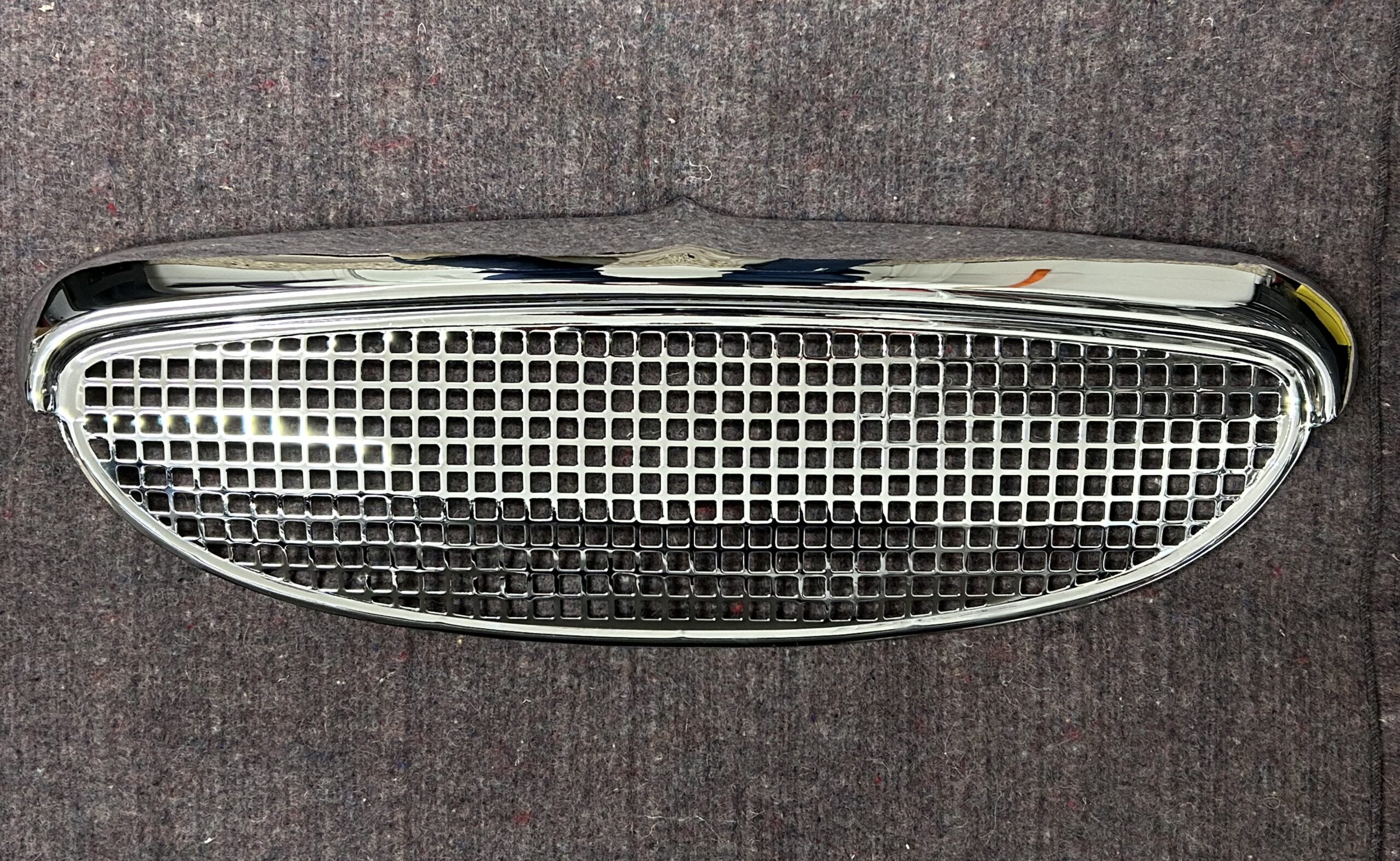
Re-chroming the grille
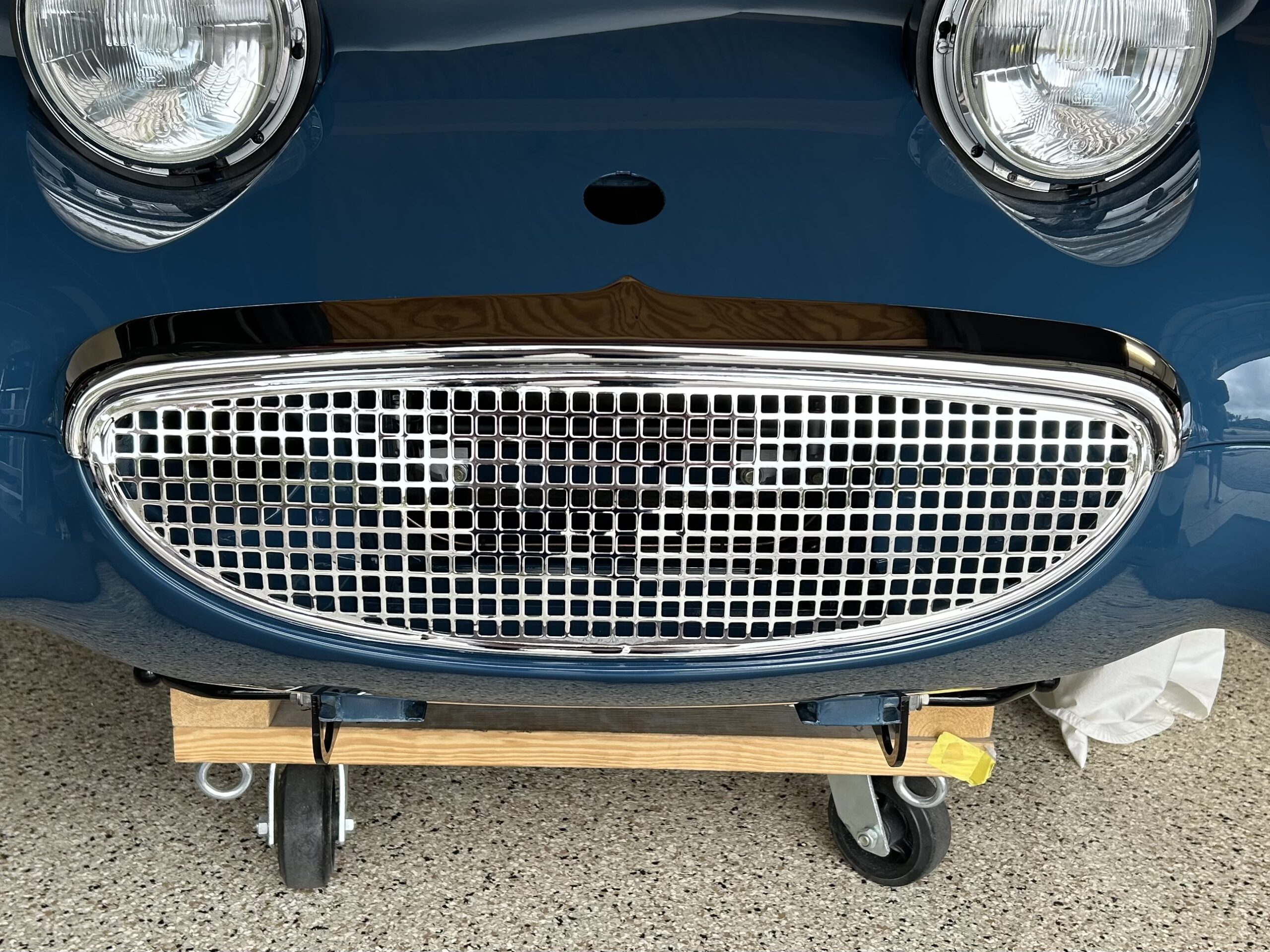
The grille is an important feature of the design of the Bugeye as it is what defines the ever-popular “smile” of the car. Modern replicas apparently do not fit very well so we decided to re-chrome the original because we knew it fit. We sent it to Dallas Plating https://dallasplatingga.com in Dallas, Georgia and we were very pleased with the quality of the work and the delivery time. It took only 3 weeks from the time we put the grille in the mail until we unpacked it. The charge for the plating was $440 and that seemed very reasonable compared to other businesses we checked.
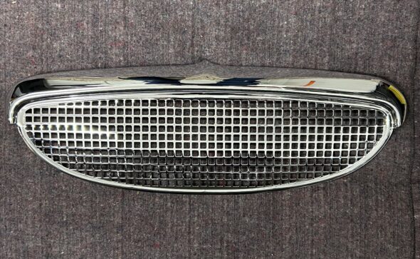
Re-chromed Grille

Re-chromed grille sitting in place
Bugeye Restoration Video Episode Ninety-five covers the installation of the items mentioned in this post:
https://vimeo.com/1046168116/36c5ceb74e?share=copy
0:00 – Rear tie down brackets – tow hooks
0:39 – Quick connect battery management cables
1:28 – Revisiting the horns
2:33 – Painting the exhaust
3:18 – Anti-sway bar installation
4:46 – Motor mounts installation
5:11 – Heater control cable attached
5:24 – Machining a new starter cable connector
6:40 – Heater and starter cable covers
6:54 – Repainting the rear deck “Flash” badge
7:30 – Re-chroming the grille