Loose Ends

This post covers several items added to the car as we begin to near the completion of this restoration.

Rear Tie down brackets (tow hooks)

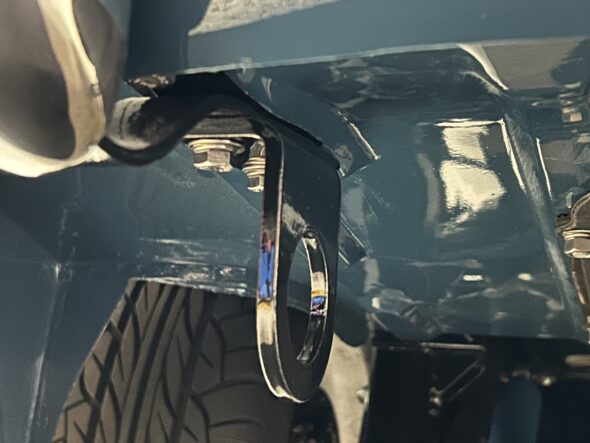
In an earlier post the front tie down brackets, or tow hooks, were mounted to the car. We also purchased rear tie down brackets or tow hooks from Q1 Classic Engineering. These are heavy duty and very nicely made. We painted them black with POR 15 and easily installed them.

Rear Tie Down Brackets

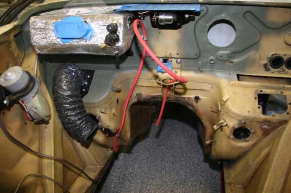
Battery management quick connect cables

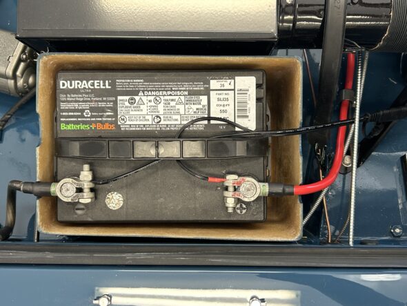
We then added some wiring to the battery so that we would have a quick connect system for the battery management charger. This is particularly useful given that we have a cover on the battery.

Battery Management Quick Connect Wiring

Horns revisited

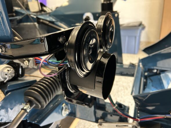
We discovered, with the installation of the bonnet gas struts, that the operation of the RH strut hit the interior horn. So, we decided to forgo the second horn and just use one. The single horn,  by the way, seemed plenty loud.

Dropping the Interior Horn

Painting the exhaust

We are not ready to install the exhaust but this was a good time to go ahead and paint it. It came from Maniflow with their familiar metallic green paint. We simply roughed it up with a little sand paper and sprayed it with Rustoleum black BBQ high temperature paint.

Maniflow Metallic Green

Exhaust painted high temperature semi-gloss black

Installing the anti-sway bar

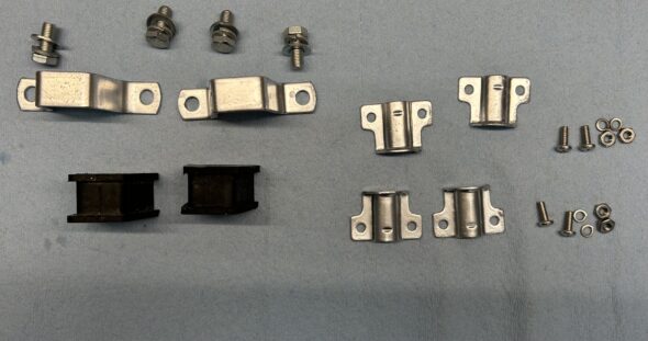
We then installed the anti-sway bar that we purchased from BugeyeGuys.com. We had previously painted the components so this turned out to be a quick job.

Anti-sway bar bits

Installing the motor mounts

The motor mounts were then installed. However, when we are ready to install the motor we will remove the RH motor mount and fix it to the motor. The LH mount will remain in the car because it is easier to leave it due to the steering column.

Heater control cable

We then connected the heater flap control cable that comes through the firewall from the heater switch to the bracket on the heater blower. 

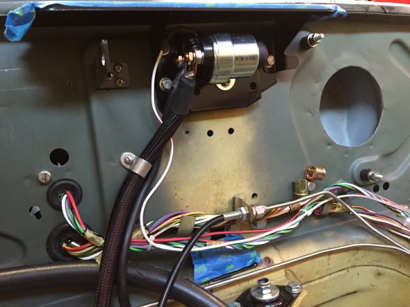
Machining a starter cable connector

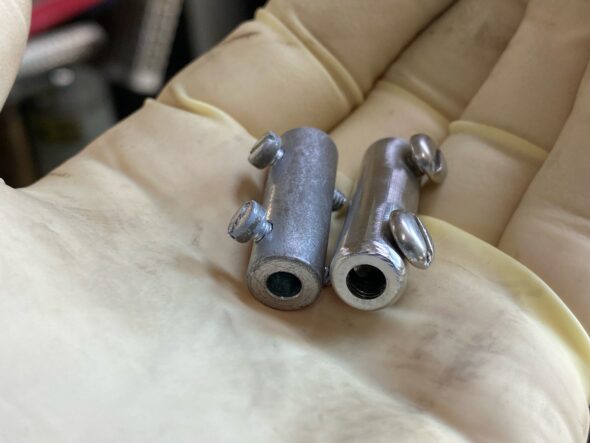
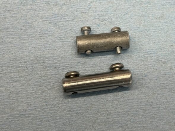
For some reason the standard connector that joins the starter cable and the starter switch is too short to do the job on the car. We know that the battery tray was replaced and perhaps the starter switch mounting bracket that is attached to the tray was slightly off? At any rate we solved this problem by machining a new connector made from a 3/8″ stainless steel bolt. Our friend Randy Forbes did the mill work for us. Thank you Randy! The new piece – almost identical but about a 1/4″ longer worked beautifully.

A new stainless starter cable connector

The new and the old

Repainting the Sprite Flash

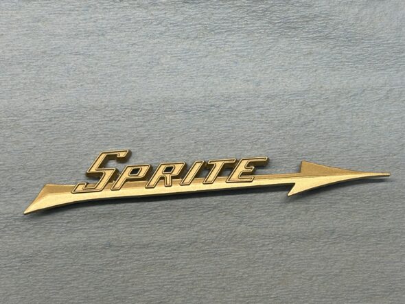
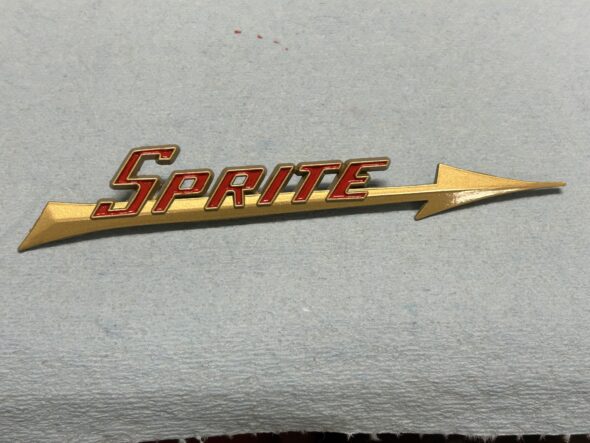
The flash emblem or badge as mounted on the rear deck of the car was gold with red lettering. Unfortunately, the replicas of the badge available from the usual suppliers is copper in color with the red lettering. So, we stripped the paint from the badge and then repainted the badge with Rustoleum metallic gold spray paint, followed by painting the red letters and finally coating the badge with Rustoleum Krystal Clear. We were pleased with the results. We are going to mount the badge later and will be using a 3M adhesive rather than mounting it through holes in the car.

The gold paint first

Followed by Red in the letters and Clear

Re-chroming the grille

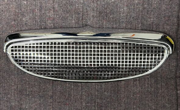
The grille is an important feature of the design of the Bugeye as it is what defines the ever-popular “smile” of the car. Modern replicas apparently do not fit very well so we decided to re-chrome the original because we knew it fit. We sent it to Dallas Plating https://dallasplatingga.com  in Dallas, Georgia and we were very pleased with the quality of the work and the delivery time.  It took only 3 weeks from the time we put the grille in the mail until we unpacked it. The charge for the plating was $440 and that seemed very reasonable compared to other businesses we checked.

Re-chromed Grille

Re-chromed grille sitting in place


Bugeye Restoration Video Episode Ninety-five covers the installation of the items mentioned in this post:

https://vimeo.com/1046168116/36c5ceb74e?share=copy

0:00 – Rear tie down brackets – tow hooks

0:39 – Quick connect battery management cables

1:28 – Revisiting the horns

2:33 – Painting the exhaust

3:18 – Anti-sway bar installation

4:46 – Motor mounts installation

5:11 – Heater control cable attached

5:24 – Machining a new starter cable connector

6:40 – Heater and starter cable covers

6:54 – Repainting the rear deck “Flash” badge

7:30 – Re-chroming the grille


Chapter 44 Restoration Assembly, Week Eleven 2/26/2007

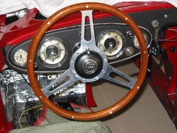
Time to install my Moto-Lita steering wheel and my rebuilt control head (trafficator) Trafficator(low res).pdf . This pdf will take a little while to download – lots of images! The installation was fairly easy and straight forward.  I inserted a length of thin wire up the tube and wrapped it around the first bullet connector on the wiring harness from the control head. I was then able to pull the wires down through the tube. I centered the wheel and tightened up the olive and nut at the bottom of the tube. Then tightened the three set screws on the steering wheel hub.

Moto-Lita steering wheel

After installing all of the electrical modifications I have made, I wanted to test things to make sure all connections were as they should be before moving on to the next task. So, even though I will disconnect them for final assembly at a later date, I wired the driving lights, headlamps, turn signals/brake lights as well as the license plate lamp.

The battery was then installed and (big breath) power applied to the system. One-by-one I checked the function of all systems. The right rear tail light turn signal did not function, the accessory lights did not turn on when the “clicker – remote control” was activated, the horns did not sound and my driving lights still needed some work. These items will be sorted out, one at a time, until everything is working properly. A little work remains, but I didn’t burn down the house or melt the car – a significant accomplishment!

I rechecked my wiring for the driving lights, made one change, and they are now functioning properly including the indicator light I installed on the new switch panel.

I made sure all of my ground connections were clean and tight and replaced the original flasher canister with a new one and now the flashers are working properly. The terminal connections are different than the original. Terminal X is equivalent to B (battery feed from fuse box — green wire),

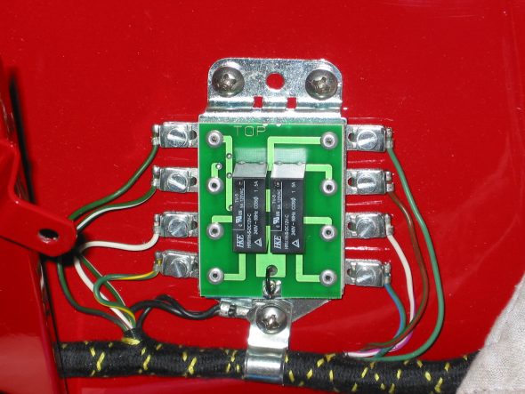
Terminal L (Load, i.e., the feed to the bulbs — green/brown wire) and terminal P (Pulse, to the dash lights — light green/purple wire). Just as an aside, I did pop open the new flasher relay box to examine it for potential problems, only to discover the circuit board of a new solid sate unit rather than one with the original design.

Flasher Relay electronic guts

Following a consult with Michael Salter, I concluded that the reason my horn was not working was that the steering box was not grounded due to the paint on the box and the frame. Once some paint was scraped away from both I obtained a solid ground and the horn “honked” properly! I rechecked my wiring for the interior accessory lighting and they now function properly also.

Battery Relocation to the Boot

Battery Relocation to the Boot

Installing the RetroAir air conditioning kit requires the relocation of the battery, and the most commonly used place is the shelf in the MK2 boot. The RetroAir kit provided a plastic battery box, battery cable and various connectors, but I chose to “upgrade” the kits components.

Battery Cable Lugs

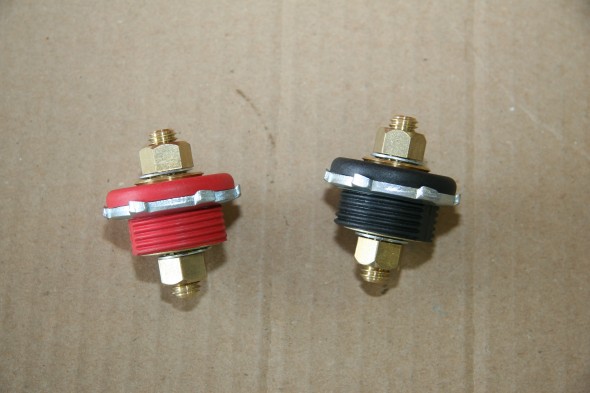
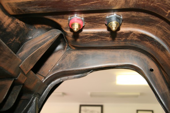
First I decided to use battery lugs to take the battery cable through the boot floor rather than taking the cable directly through a rubber grommet in the floor. I used Waytek’s “Battery Feeder Stud” for this purpose. http://www.waytekwire.com/products/ One in black for the ground cable, part# 36663, and one in red for the power cable, part# 3662. I located these to the right of the battery mounting.

Waytek Battery Lugs

Waytek Battery Lugs

Battery Lugs Mounted - Under Carriage View

Battery Lugs Mounted – Under Carriage View

Battery Lug Rubber Covers

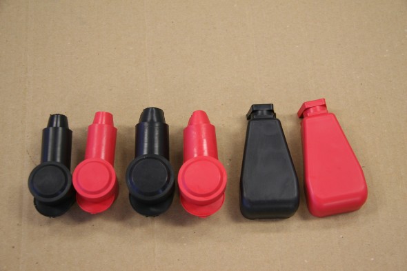
I found some rubber covers for the battery terminals and lugs that work quite well. They were sourced on-line from the Electrical Hub.

http://www.electricalhub.com/battery-terminals-and-lugs/insulator-battery-boots

Battery Terminals and Lugs Rubber Covers

Battery Terminals and Lugs Rubber Covers

Battery Hold Down Mount

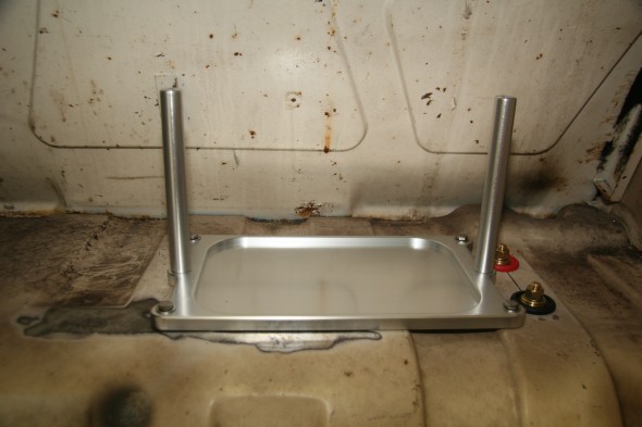
While the plastic box provided in the RetroAir kit would certainly work, it took up considerable space as well as not being very attractive – even if it does go in the boot! I chose to use a Billet Specialties product http://www.billetspecialties.com, part# 248910, that in my opinion is both attractive and space saving. I mounted this as far to the right side of the car as possible. The tray mounts to the boot floor with four 1/4″ – 24 x 1″ hex head stainless bolts, flat and shake proof washers.

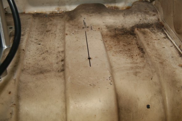
Markings to Locate Battery Tray

Markings to Locate Battery Tray

Billet Specilaties Battery Tray Mounted

Billet Specialties Battery Tray Mounted

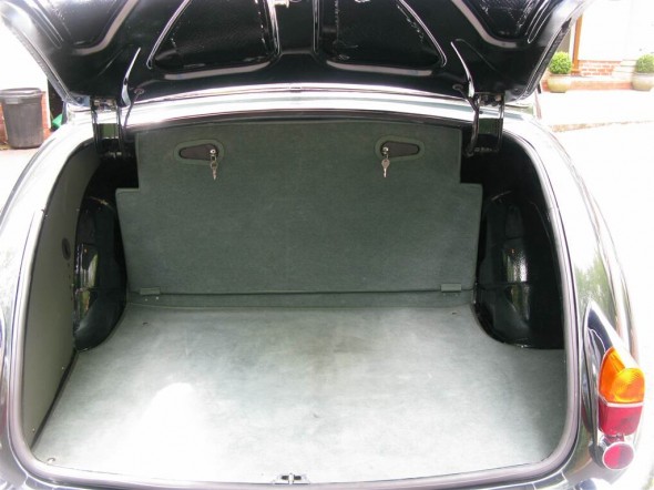
I intend to make a carpet-covered plywood panel to hide the rear compartment of the boot. Similar to this one:

Boot Panel

Boot Panel

Battery Isolator Switch

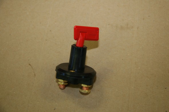
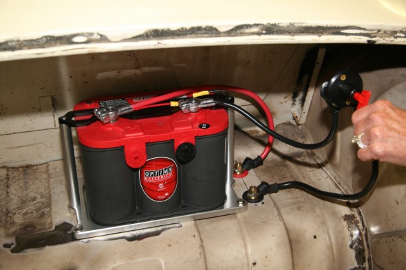
And, I will install a Waytek battery Isolator Switch with a detachable key, part# 44075, in the upper right corner of the panel. It certainly won’t stop professional car thieves but it does provide one more deterrent to the criminal. The lower photo shows the Optima Red Top battery (borrowed from my Austin Healey for fitting purposes) and the approximate location of the isolator switch. A 20″ red power lead  part #35976 also from Waytek was used to provide the connection from the battery to the red lug. A 15″ black ground lead, part number 35965, was used to connect the battery to the black lug.

Waytek Battery Isolator Switch

Waytek Battery Isolator Switch

Battery Mounted with Isolator Switch

Battery Mounted with Isolator Switch

Battery Cable to the Engine Bay

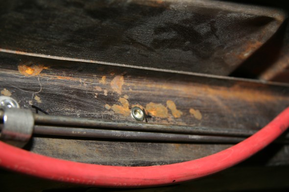
I debated about running the battery cable along the RH frame rail or to route the cable through the interior to the engine bay. I ultimately decided to mount it on the frame rail. The brake line to the rear axle and the fuel line from the fuel filter in the engine bay to the fuel pump also run along the RH frame rail.

I used a combination of single and double stainless steel clamps to secure the battery cable, brake line and fuel line to the frame. http://tinyurl.com/kuzn3k8  The upper clip was used for the battery cable and the fuel and brake lines were housed in the lower clip.

Double Line Clamp

Double Line Clamp

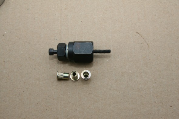
I used #10-24 rivet nuts or nut serts set into the frame rail to attach the clamps. The rivets require a 19/64″ hole in the metal stock and conveniently the holes already in the frame for the original brake/fuel line spring clips were that size of at east very close to it. This meant that I did not have to drill any new holes. The rivet nuts are easy to install using an inexpensive little tool. The nuts are screwed on to the threaded rod and inserted into the frame hole. One holds the larger nut (7/8″) stationary while tightening the outside smaller (11/16″) nut. This pulls the nut firmly against the frame rail creating essentially a captive nut.

Rivet Nuts and Tool

Rivet Nuts and Tool

#10-24 Rivet nut installed in frame

#10-24 Rivet nut installed in frame

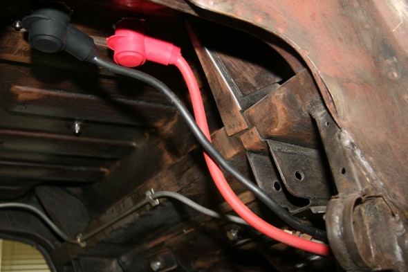
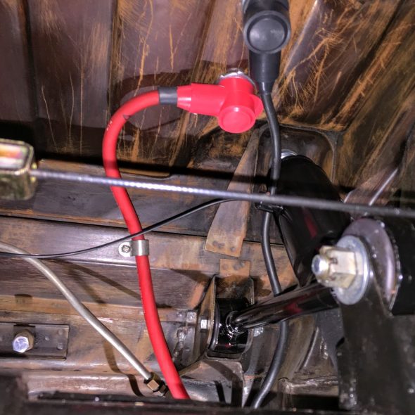
The following images show the installation of the cable and brake/fuel lines. The battery cables runs from the lugs below the boot floor. the black ground cable is securely bolted to the frame while the red cable runs to the engine bay.

Wiring From Battery Lugs

Wiring From Battery Lugs

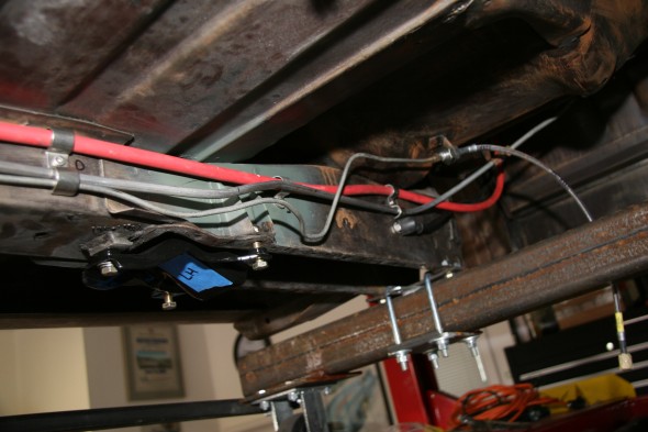
I left some slack in the cables because I still need to install the rear suspension torque arm and panhard rod which may require moving the cables a bit.

Spaghetti?

Spaghetti?

Battery Cable Routing from Rear Lugs to Starter Solenoid

Battery Cable Routing from Rear Lugs to Starter Solenoid

I will cut the cable to the desired length, solder a terminal on the end and mount it on the rear-most solenoid terminal post after more engine bay items are mounted.

Battery Cable Routed from Boot to Starter solenoid

Battery Cable Routed from Boot to Starter solenoid

The image below shows the battery cable trimmed to the proper length, covered with Techflex F6 wire sheathing and mounted to the front-most post on the starter solenoid. The cable to the starter is mounted to the rear-most post on the starter solenoid. Total cable length was about 150 inches.

Starter Solenoid, Battery Cable, Starter Cable

Starter Solenoid, Battery Cable, Starter Cable

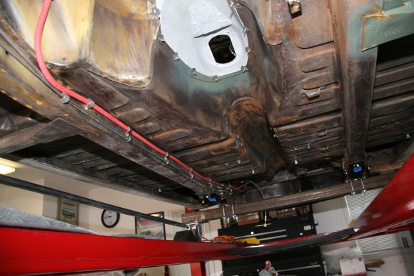
This image shows the final cable locations in the rear after the rear suspension components were installed:

Battery Cables from Boot Final Adjustment