Time to install my Moto-Lita steering wheel and my rebuilt control head (trafficator) Trafficator(low res).pdf . This pdf will take a little while to download – lots of images! The installation was fairly easy and straight forward. I inserted a length of thin wire up the tube and wrapped it around the first bullet connector on the wiring harness from the control head. I was then able to pull the wires down through the tube. I centered the wheel and tightened up the olive and nut at the bottom of the tube. Then tightened the three set screws on the steering wheel hub.
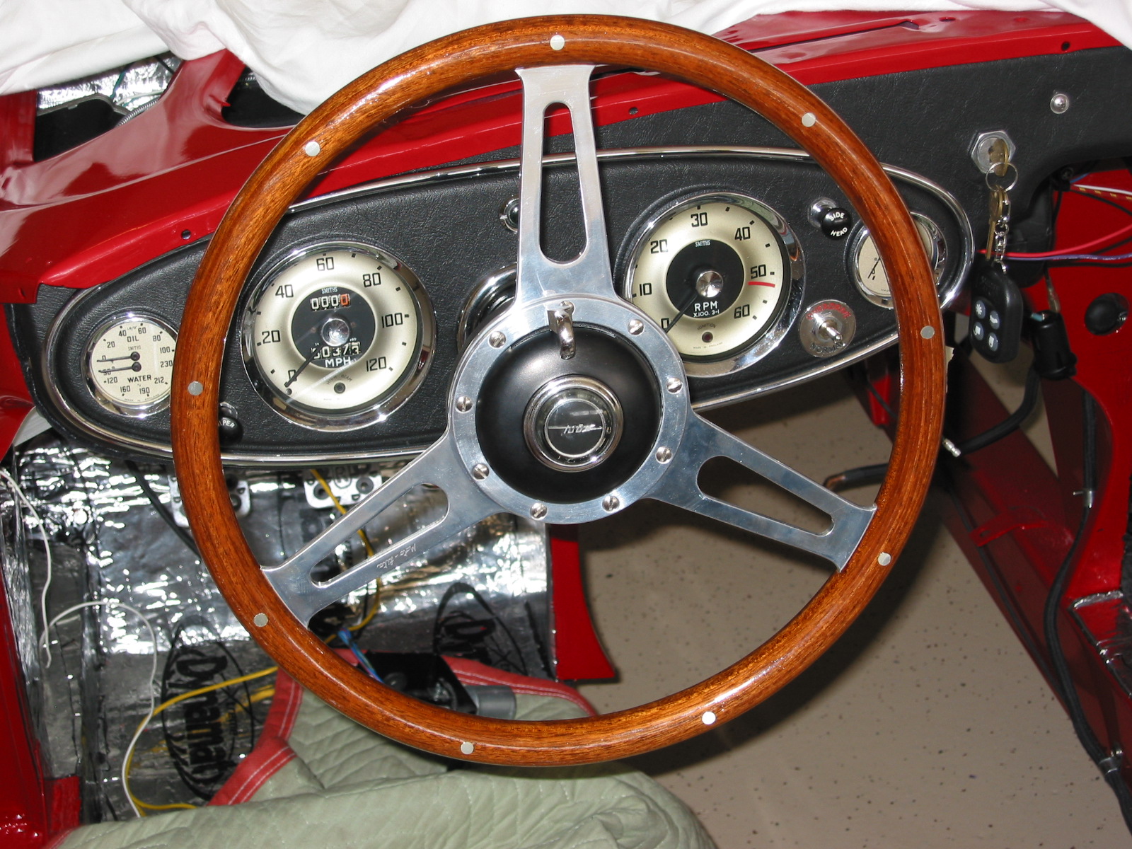
Moto-Lita steering wheel
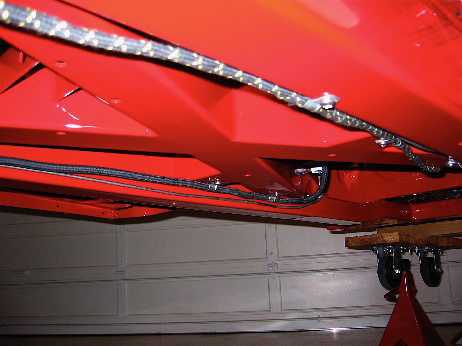
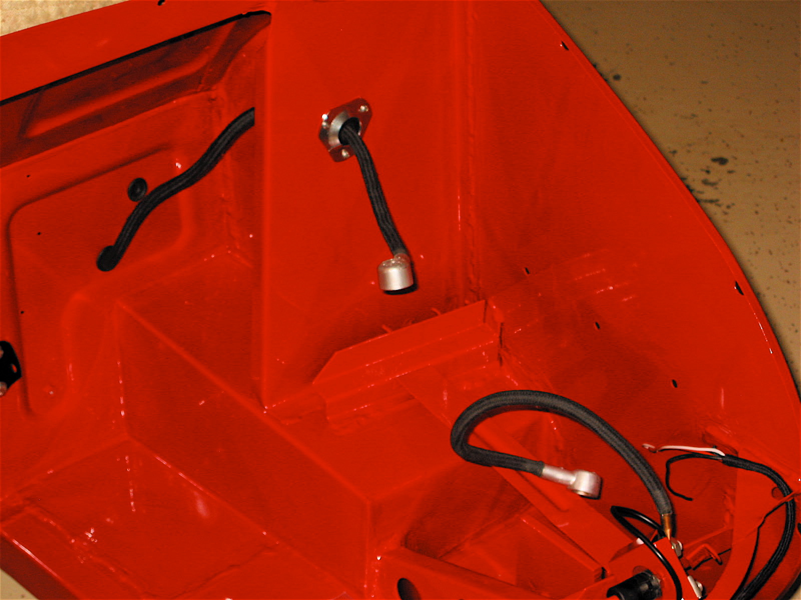
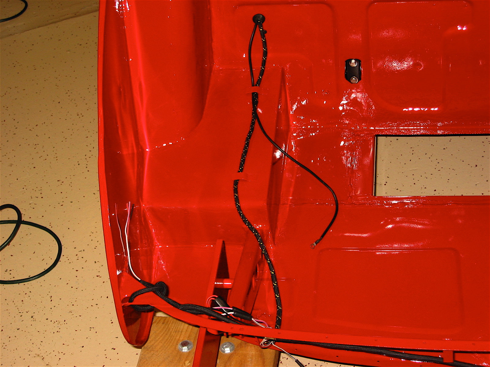
After installing all of the electrical modifications I have made, I wanted to test things to make sure all connections were as they should be before moving on to the next task. So, even though I will disconnect them for final assembly at a later date, I wired the driving lights, headlamps, turn signals/brake lights as well as the license plate lamp.
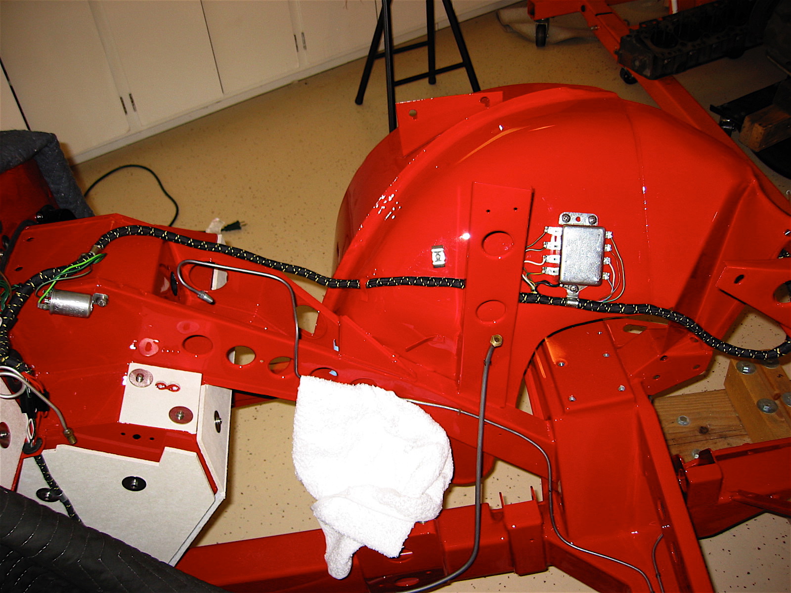
The battery was then installed and (big breath) power applied to the system. One-by-one I checked the function of all systems. The right rear tail light turn signal did not function, the accessory lights did not turn on when the “clicker – remote control” was activated, the horns did not sound and my driving lights still needed some work. These items will be sorted out, one at a time, until everything is working properly. A little work remains, but I didn’t burn down the house or melt the car – a significant accomplishment!
I rechecked my wiring for the driving lights, made one change, and they are now functioning properly including the indicator light I installed on the new switch panel.
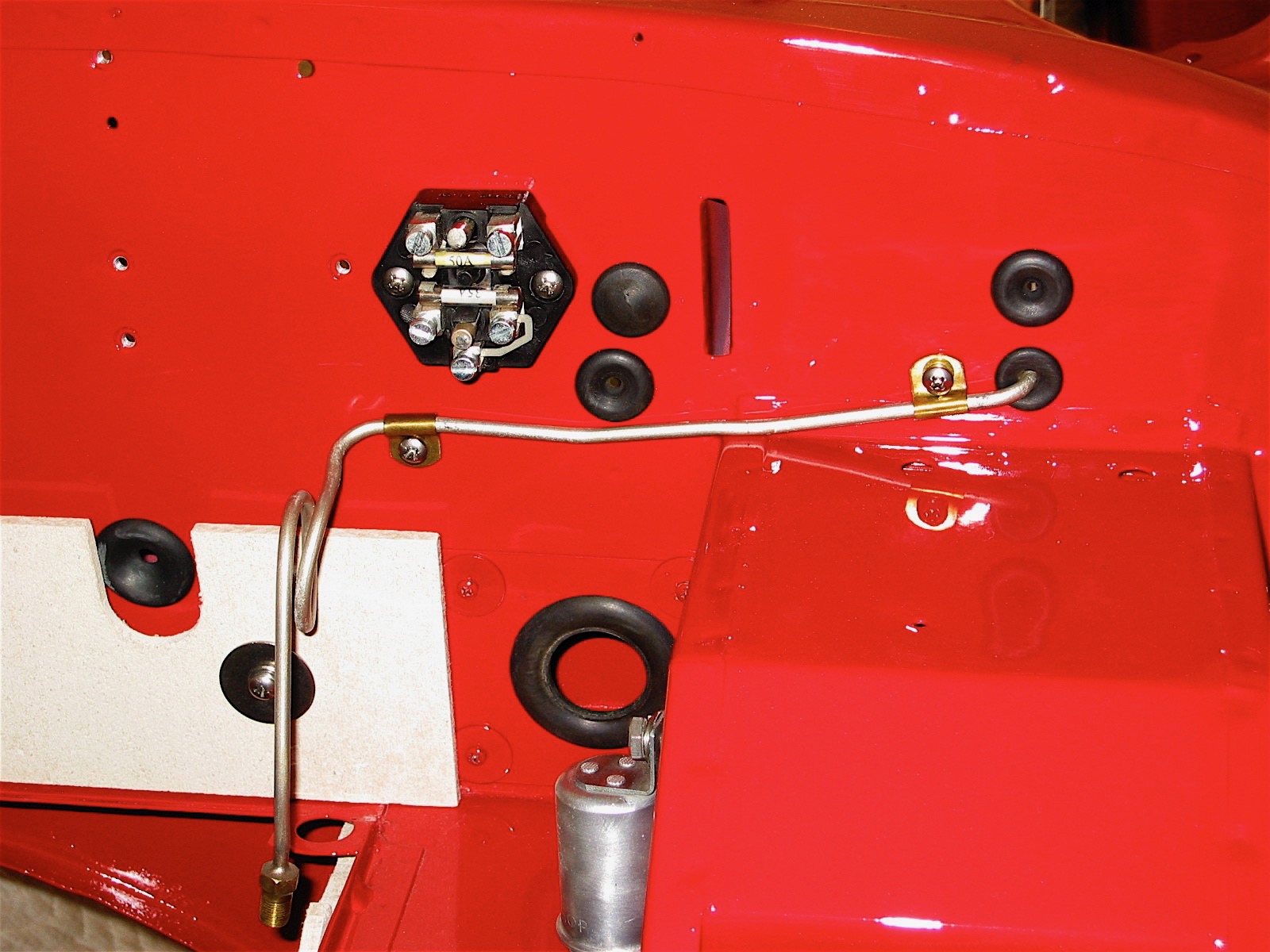
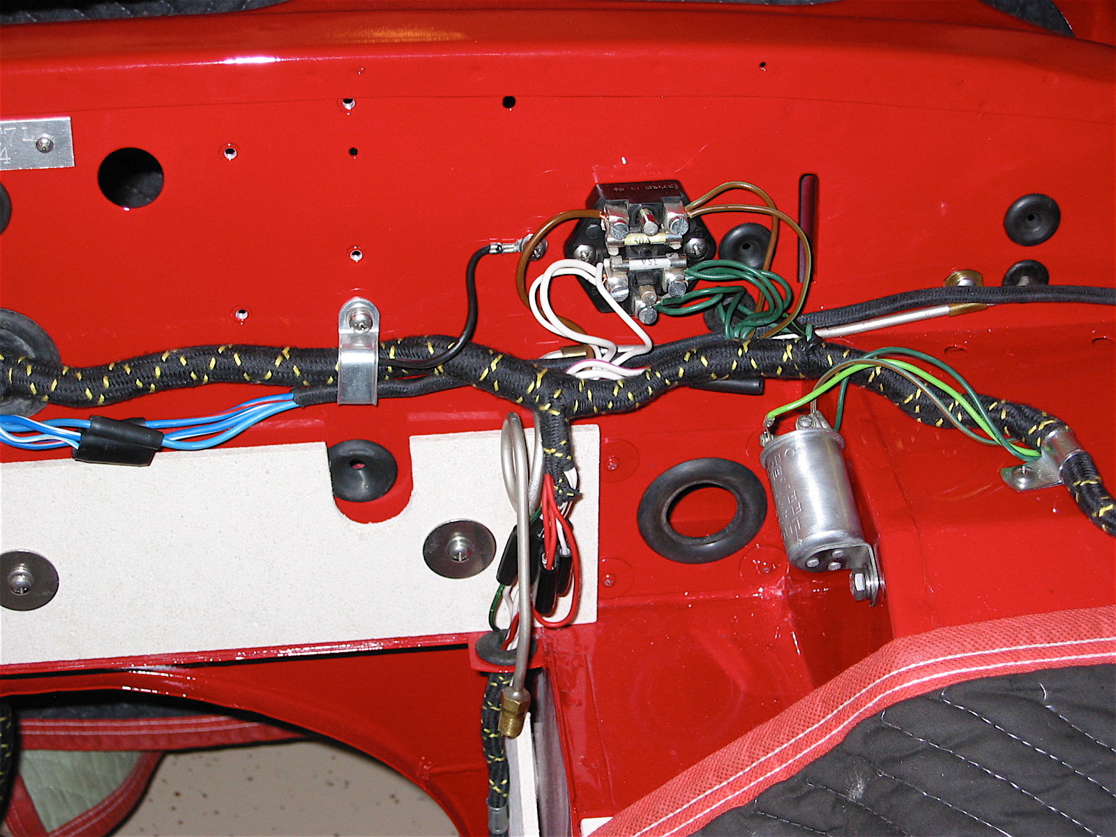
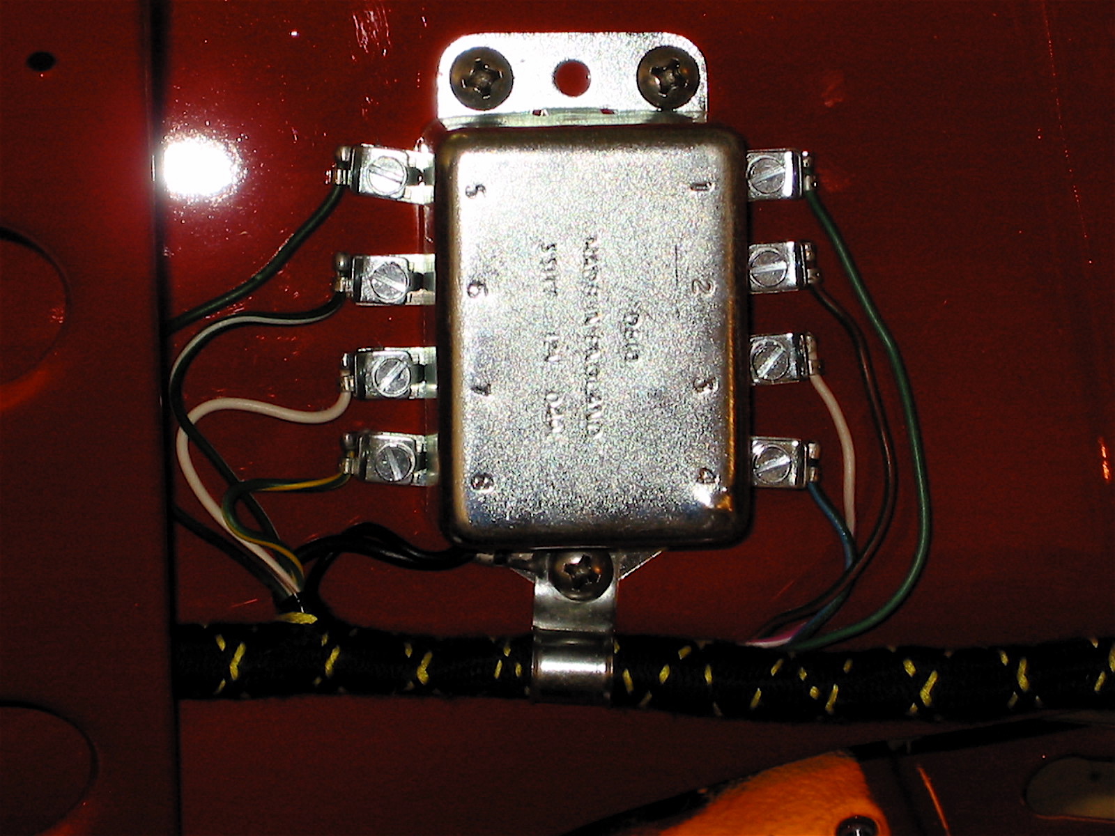
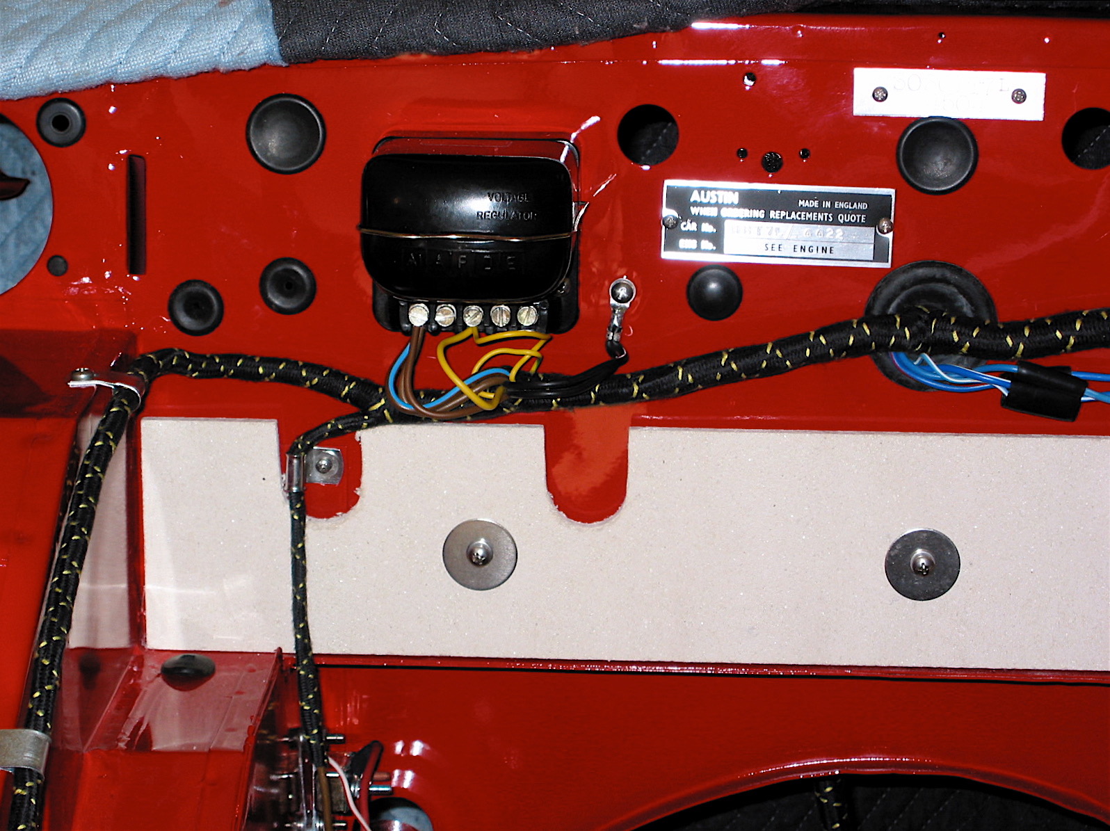
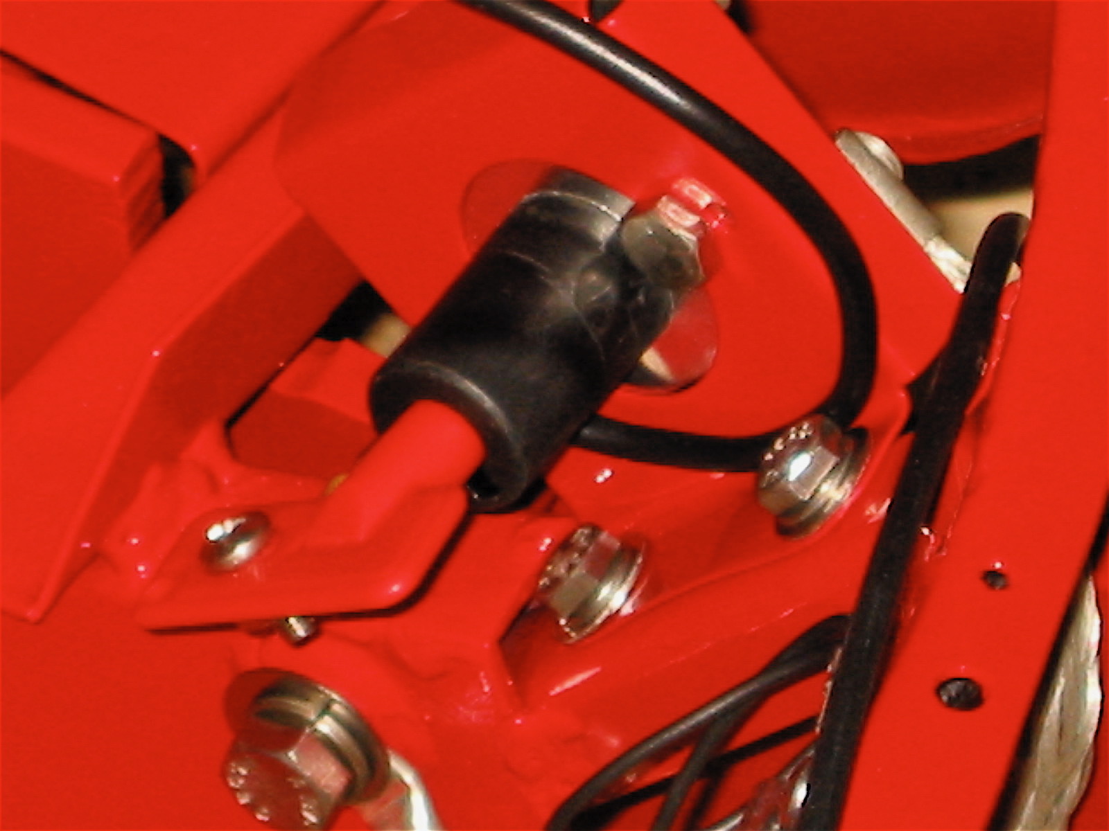
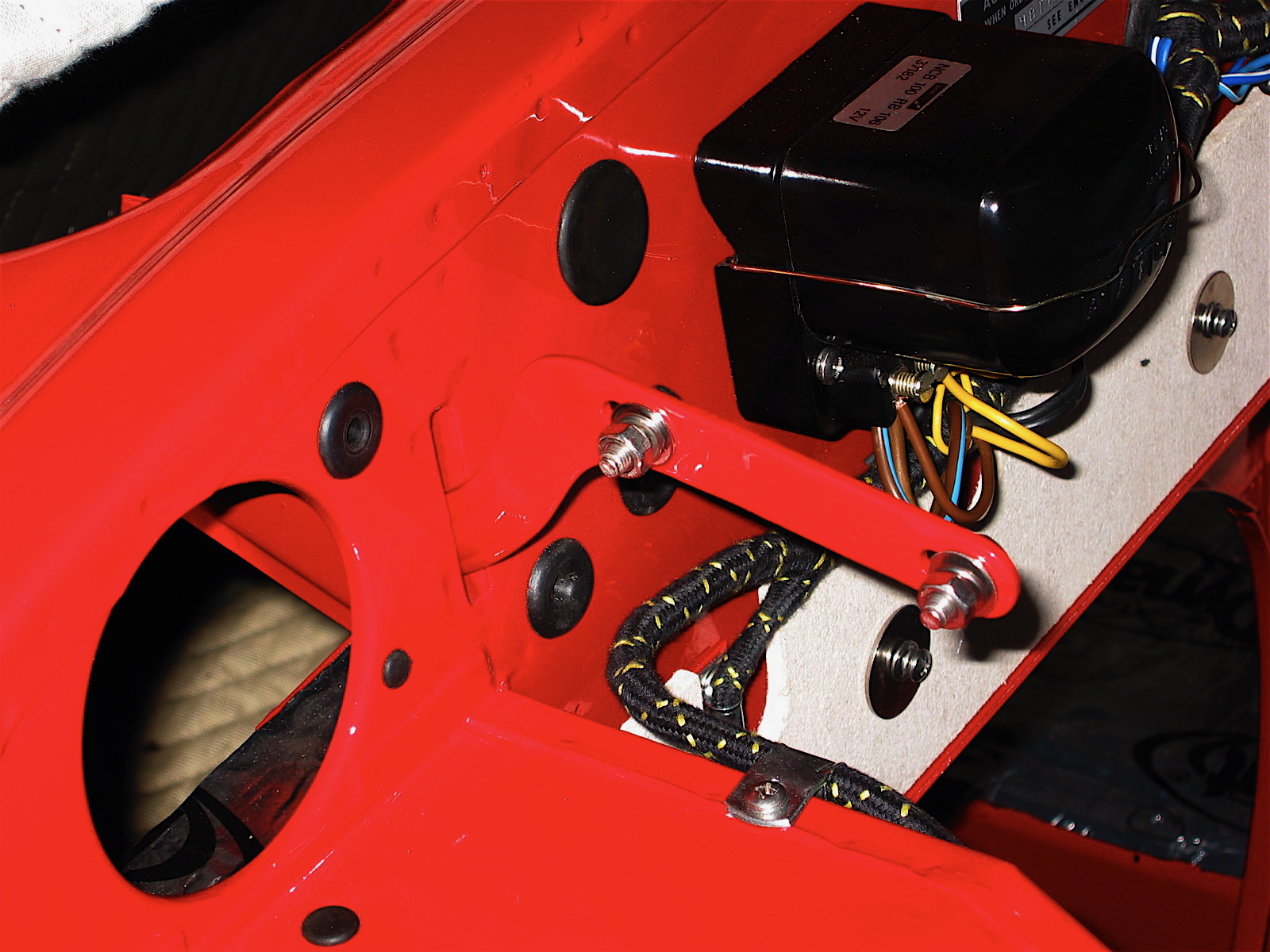
I made sure all of my ground connections were clean and tight and replaced the original flasher canister with a new one and now the flashers are working properly. The terminal connections are different than the original. Terminal X is equivalent to B (battery feed from fuse box — green wire),
Terminal L (Load, i.e., the feed to the bulbs — green/brown wire) and terminal P (Pulse, to the dash lights — light green/purple wire). Just as an aside, I did pop open the new flasher relay box to examine it for potential problems, only to discover the circuit board of a new solid sate unit rather than one with the original design.

Flasher Relay electronic guts
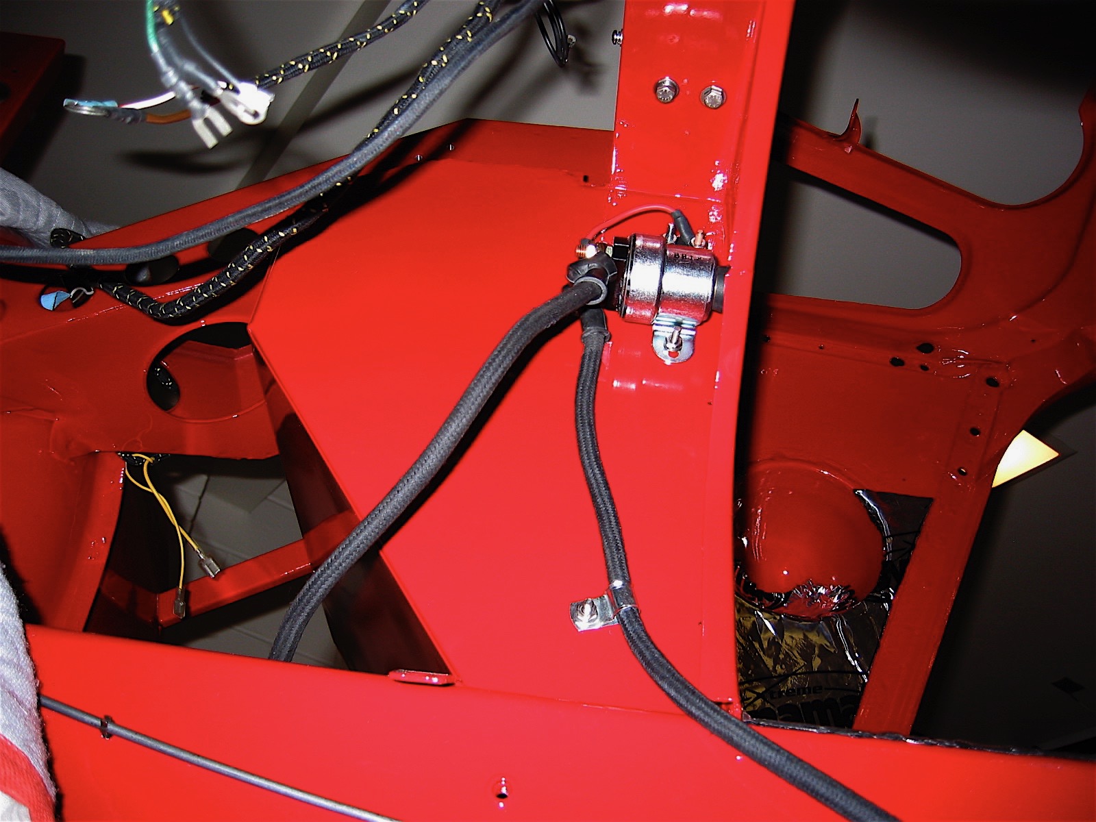
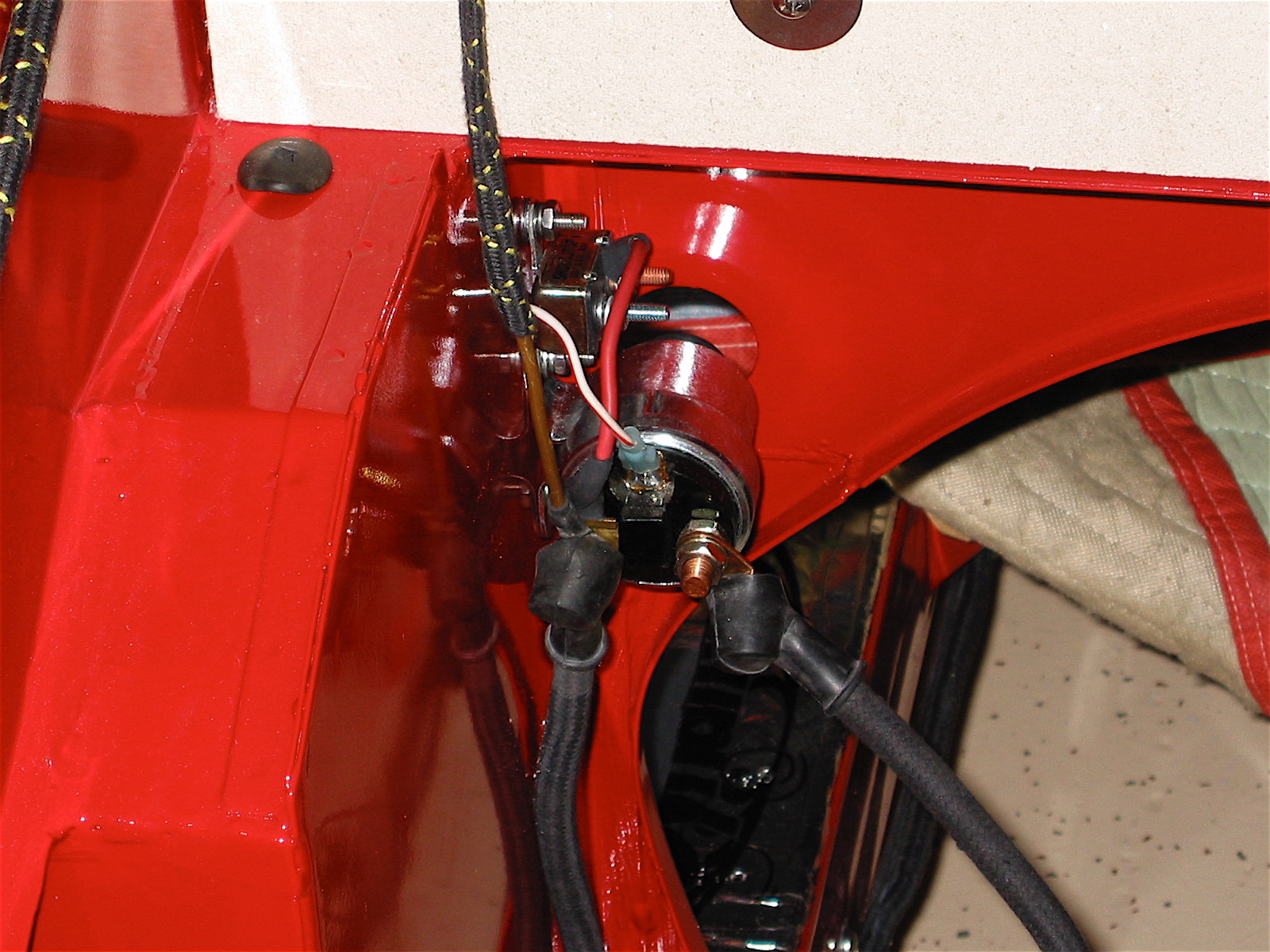
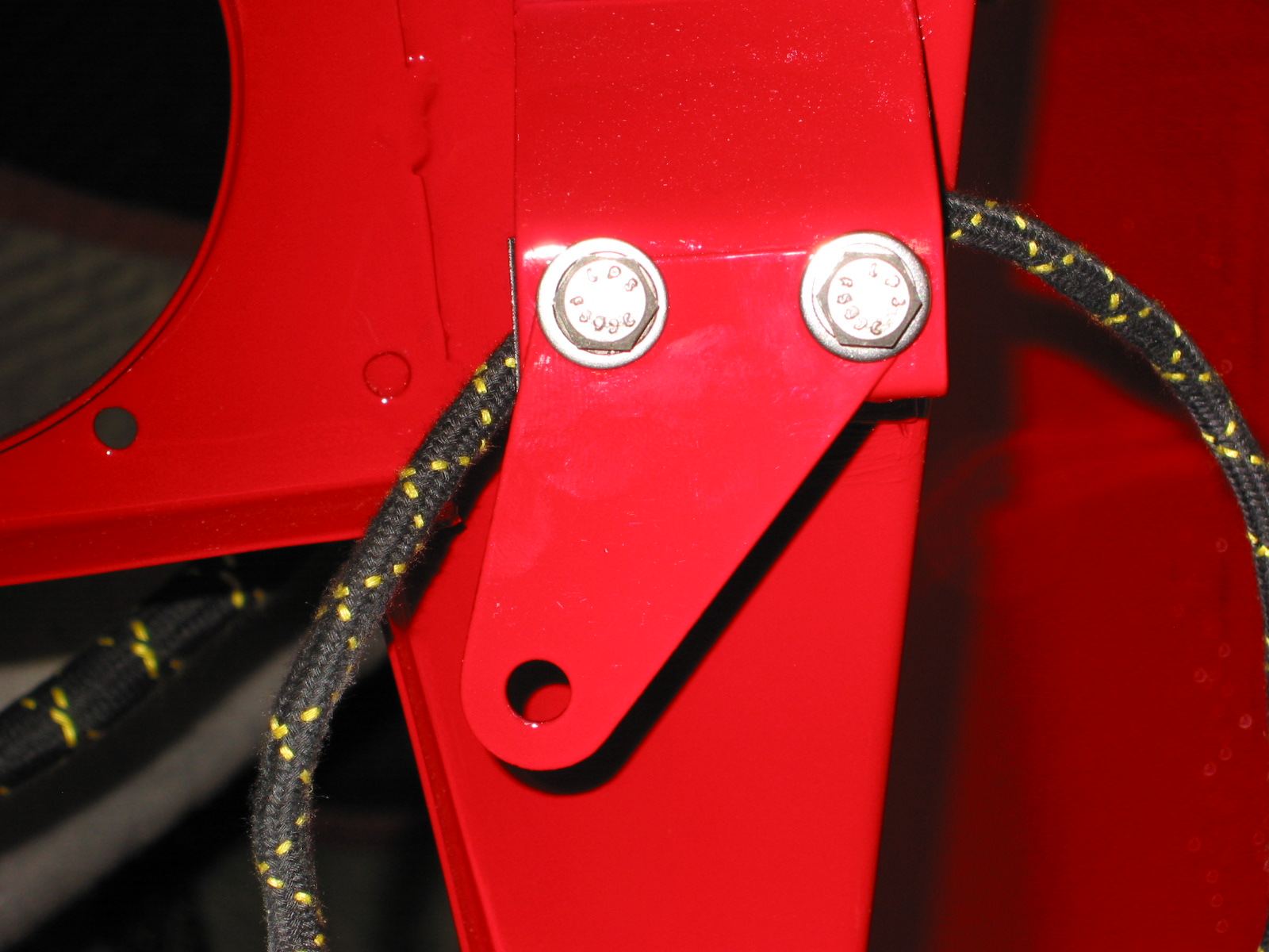
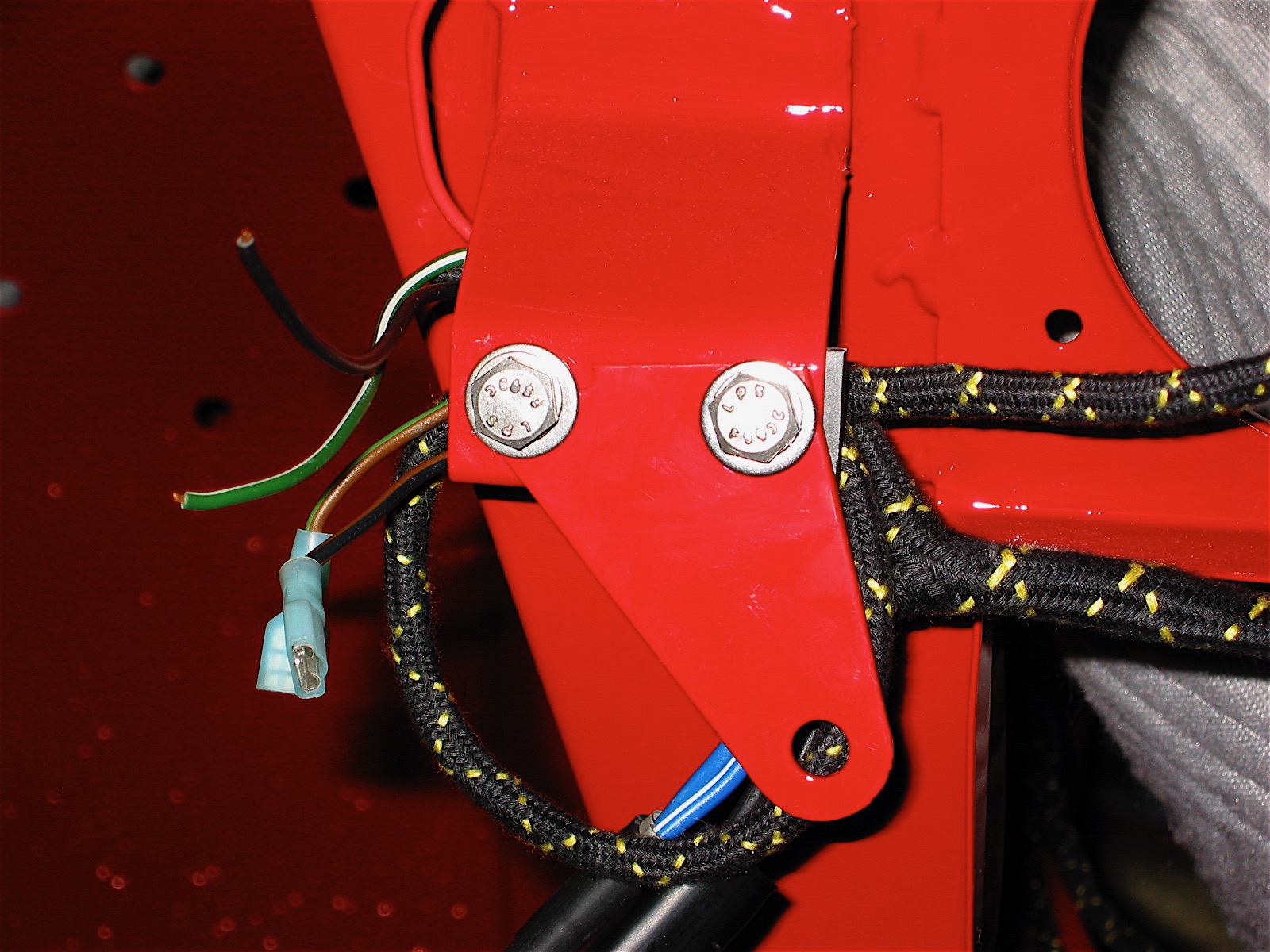
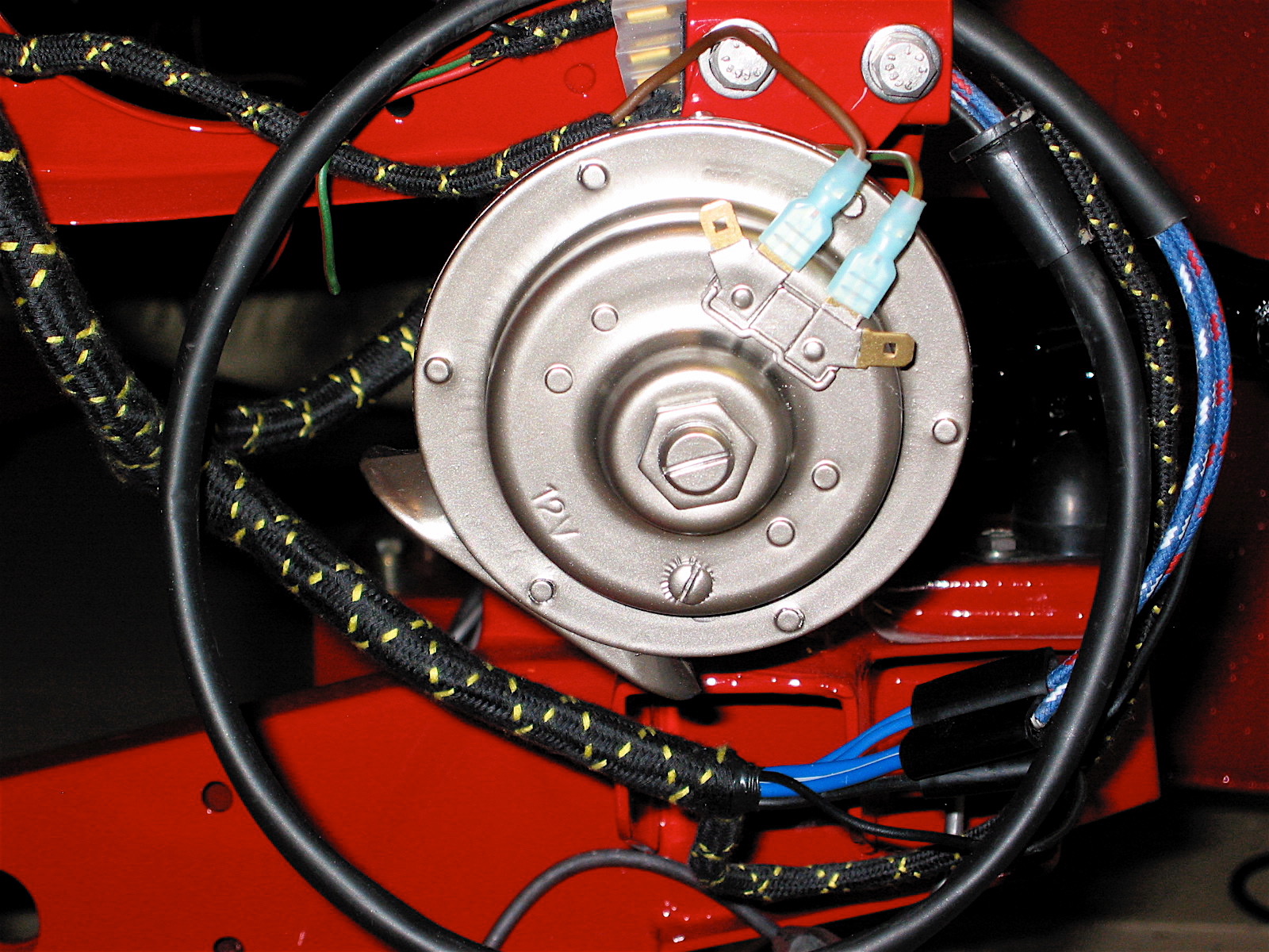
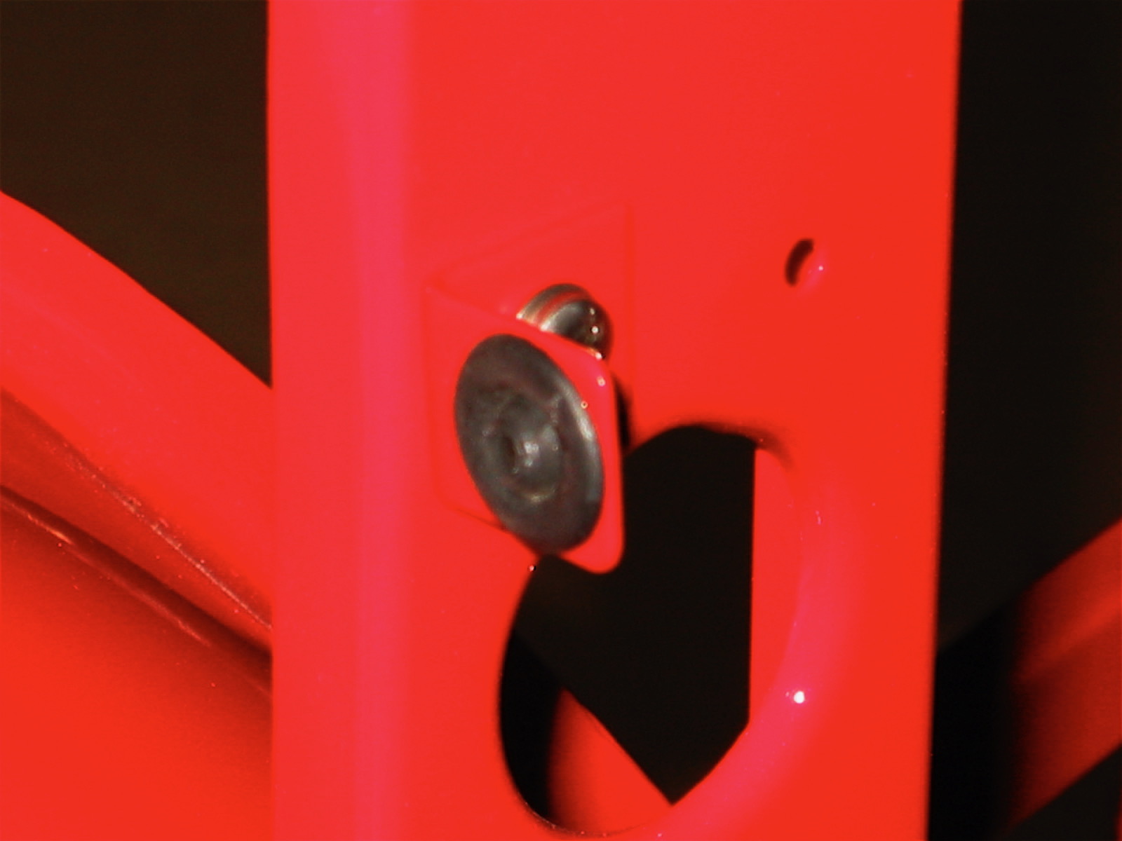
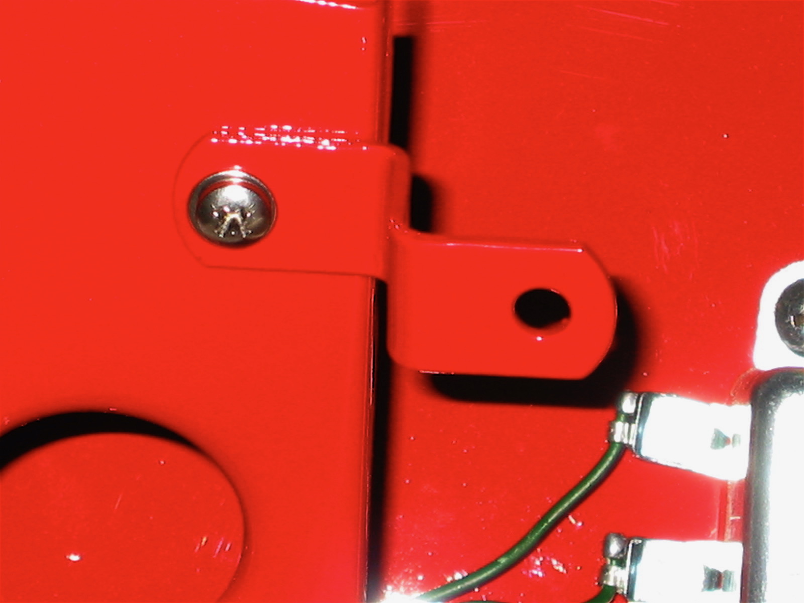
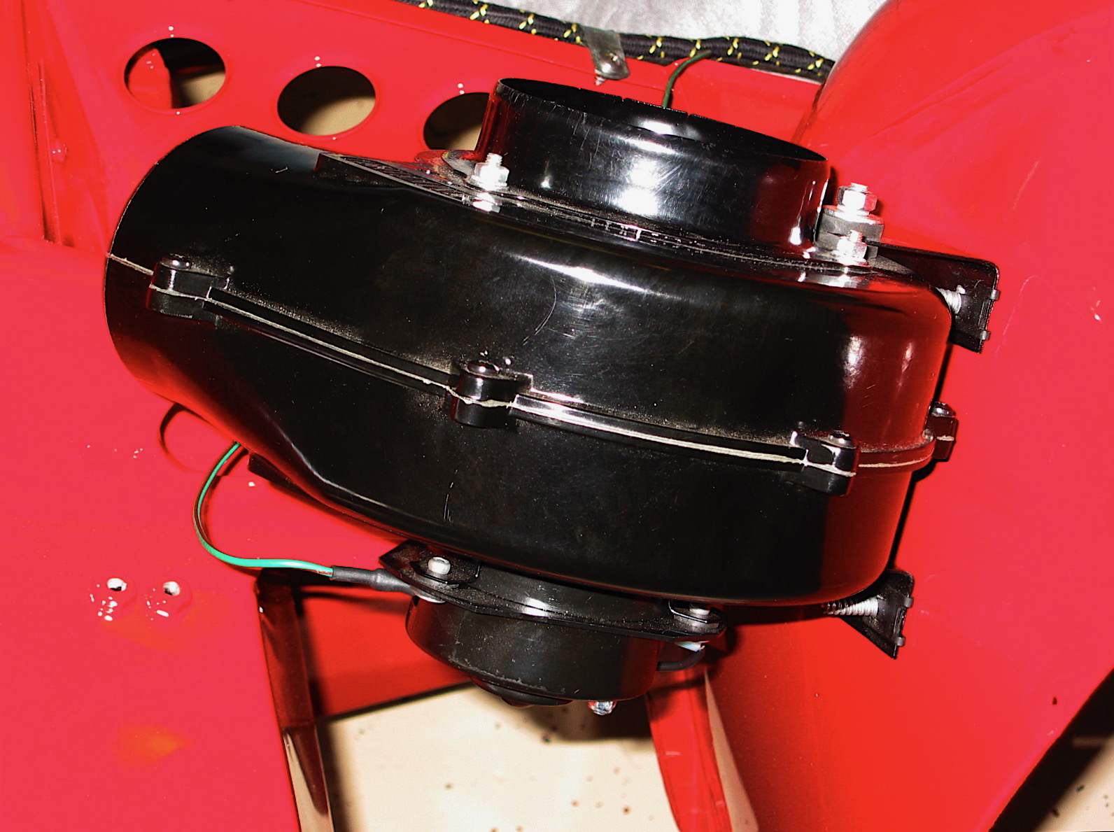
Following a consult with Michael Salter, I concluded that the reason my horn was not working was that the steering box was not grounded due to the paint on the box and the frame. Once some paint was scraped away from both I obtained a solid ground and the horn “honked” properly! I rechecked my wiring for the interior accessory lighting and they now function properly also.