I ordered some 6mm black rubber tubing from British Wiring to sheath the choke cables. It gave a slightly loose fit, but I think it will be fine. I installed it on both cables. I painted and installed the propshaft made for me by Dale Engineering.
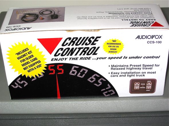
I purchased the cruise control unit, made by Audiovox, from J. C. Whitney.
It was fairly inexpensive and appeared to be a high quality kit. A complete set of installation instructions is available from the Cruise Control pdf document I created. Not much helpful information was available from other Healey owners who had done the install, although I did find one well done article that is in the October, 2002 edition of the Healey Marque Magazine. Alan Teague and Carl Brown from North Carolina did provide some useful tips and photos and I am grateful to both of them. Installing the Audiovox CCS
(This is a large file that takes a while to open, be patient)
The key components included installing the magnet and sensor at the propshaft, the location of the servo canister, the vacuum line and throttle connections, the control module, and the wiring.
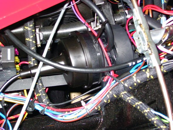
I installed the servo above the dash panel support bracket to the right of the steering column with two 11” plastic ties, rather than using the supplied metal bracket. I know from other’s accounts that the unit makes some noise when it is operating, but not knowing if it is an offensive level or not, I wanted to mount the servo temporarily. If the unit turns out to be noisy, I will move it into the engine bay later.
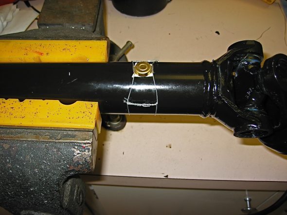
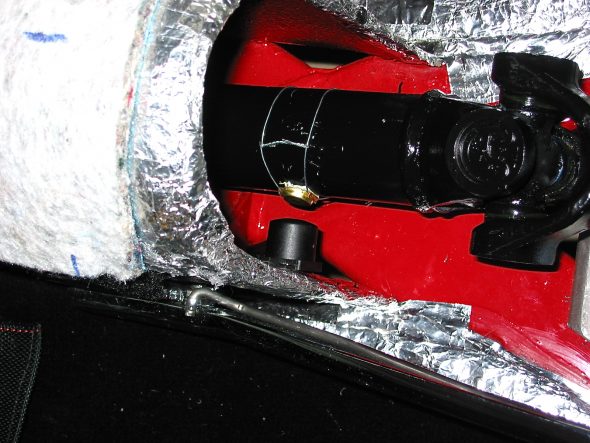
Wiring the magnet to the propshaft should really be done with the shaft removed from the car if you want to do a nice installation. I located the magnet while the propshaft was in the car, aligned the sensor and mounted it on the right side of the gearbox tunnel, removed the propshaft and safety wired the magnet and then reinstalled the propshaft. If you want to do a nice job, I highly recommend using safety wire twisting pliers. They make the job much easier and result in higher quality work. I got my pliers from Aircraft Spruce.
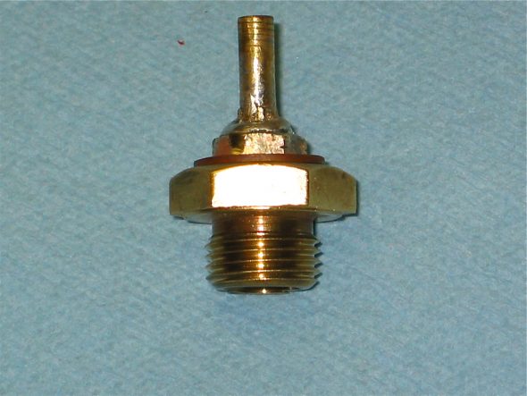
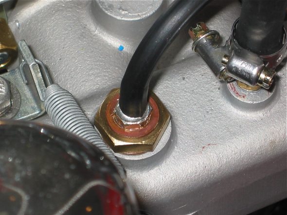
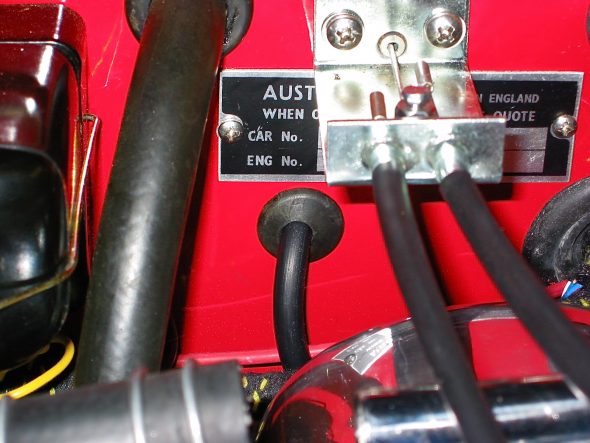
Installing the supplied rubber vacuum line required taking the line through a firewall rubber grommet that was not previously used, and then modifying the larger nut on the intake manifold with a fitting to permit connecting the hose for vacuum at the manifold.
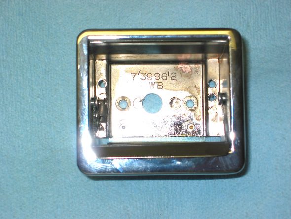
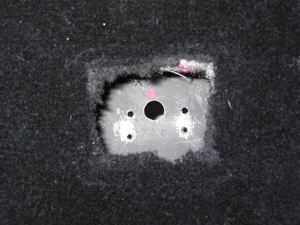
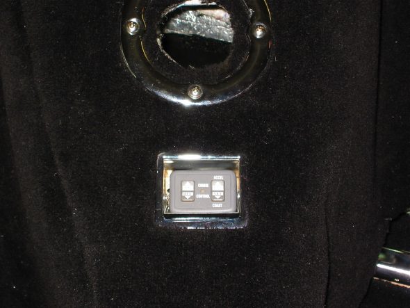
After setting up the magnet, sensor and vacuum servo the next task was to complete the installation of the cruise control panel. I followed the course of others, taking advantage of the panel’s small size and installing it in the ash tray. This provides a convenient location for controls and also “hides” the panel when desired. I simply drilled a 1/2” hole in the bottom of the ash tray and in the gearbox tunnel bracket for the ash tray to permit the routing of the wiring.
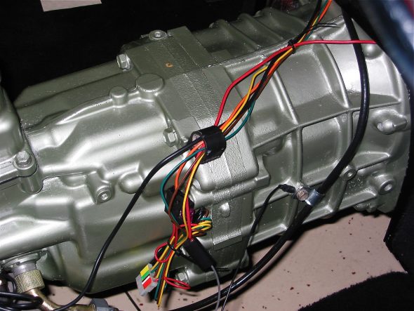
The cruise control wiring appears daunting at first, but with patience it can be accomplished by a novice. Since on the BT7 the speedometer cable runs behind the gearbox extension, I decided to run the cruise control wires down the same path to get all of my wiring “under” the gearbox cover. Again, details are provided in the Cruise Control pdf file. Black, twin tailed wire to the magnet sensor, black single wire to ground, grey wire to headlamp switch for illumination of the control panel in the ash tray, red wire to the light green wire on the brake switch that is hot whether the brake pedal is depressed or not, the purple wire to the green/purple wire on the brake switch (the one that is hot when the pedal is depressed), blue wire to (-) terminal on the coil, yellow, green and purple and red wire to the 4-pin connector, the orange fused wire to a power source when the ignition is switched on.
With the wiring complete, the only remaining task is locating and connecting the throttle control. That job will have to wait for next week’s work.

