
Handbrake
Handbrake Calipers
The mechanical handbrake unit is mounted on and above the caliper bodies on the rear brakes by means of pivot bolts and forked retraction plates. The Jaguar Service Manual states: “The handbrakes are self-adjusting to compensate for friction pad wear and automatically provide the necessary clearance between the brake discs and the friction pads.”
“When the handbrake lever in the car is operated, the operating lever (A) is moved away from the friction pad carrier (B) and draws the friction pads (F) together. Under normal conditions when the lever is released the pawl (C) in the adjusting mechanism returns to its normal position, thus the normal running clearance between the brake discs and the friction pads is maintained.”
“In the event of there being increased clearance, the pawl will turn the ratchet nut (D) on the bolt thread drawing the adjuster bolt (E) inwards and bringing the friction pads closer to the brake disc until the normal running clearance is restored.”

Handbrake Calipers
This image from the Jaguar Service Manual illustrates the adjusting mechanism of the “self-adjusting” handbrakes used on later model MK2s.

MK2 Handbrake Adjusting Mechanism
This is a great video done by davejaguar66@gmail.com who rebuilt his XKE brake caliper assemblies:
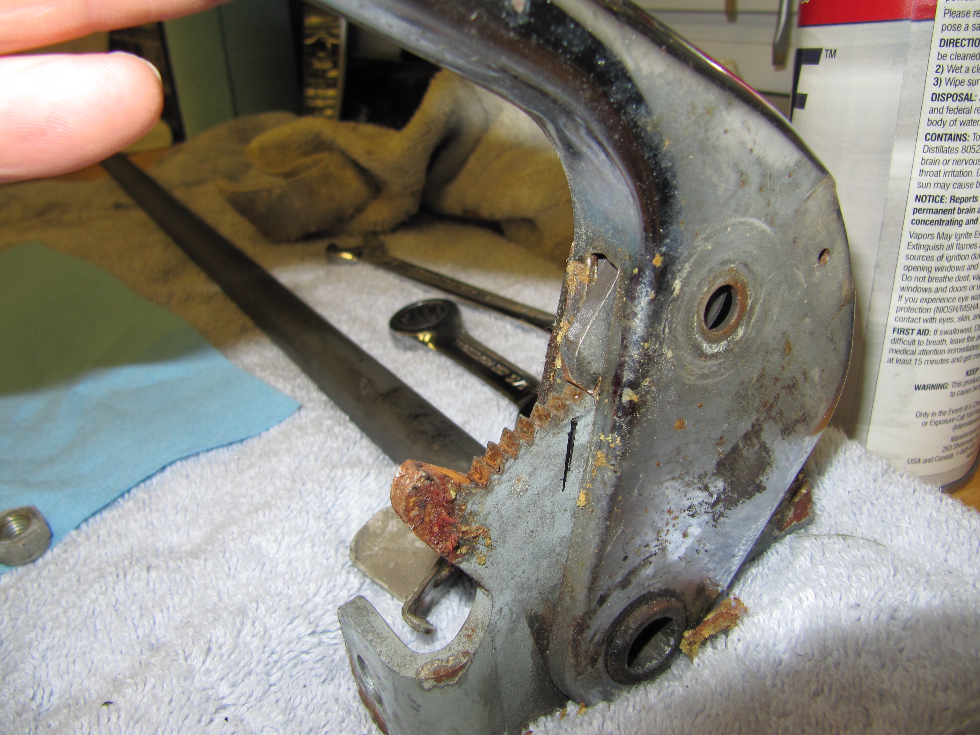
When I removed the cover from the handbrake lever I discovered globs of what I expect was fifty year old grease. The covers looked like they had never been removed. What a mess.
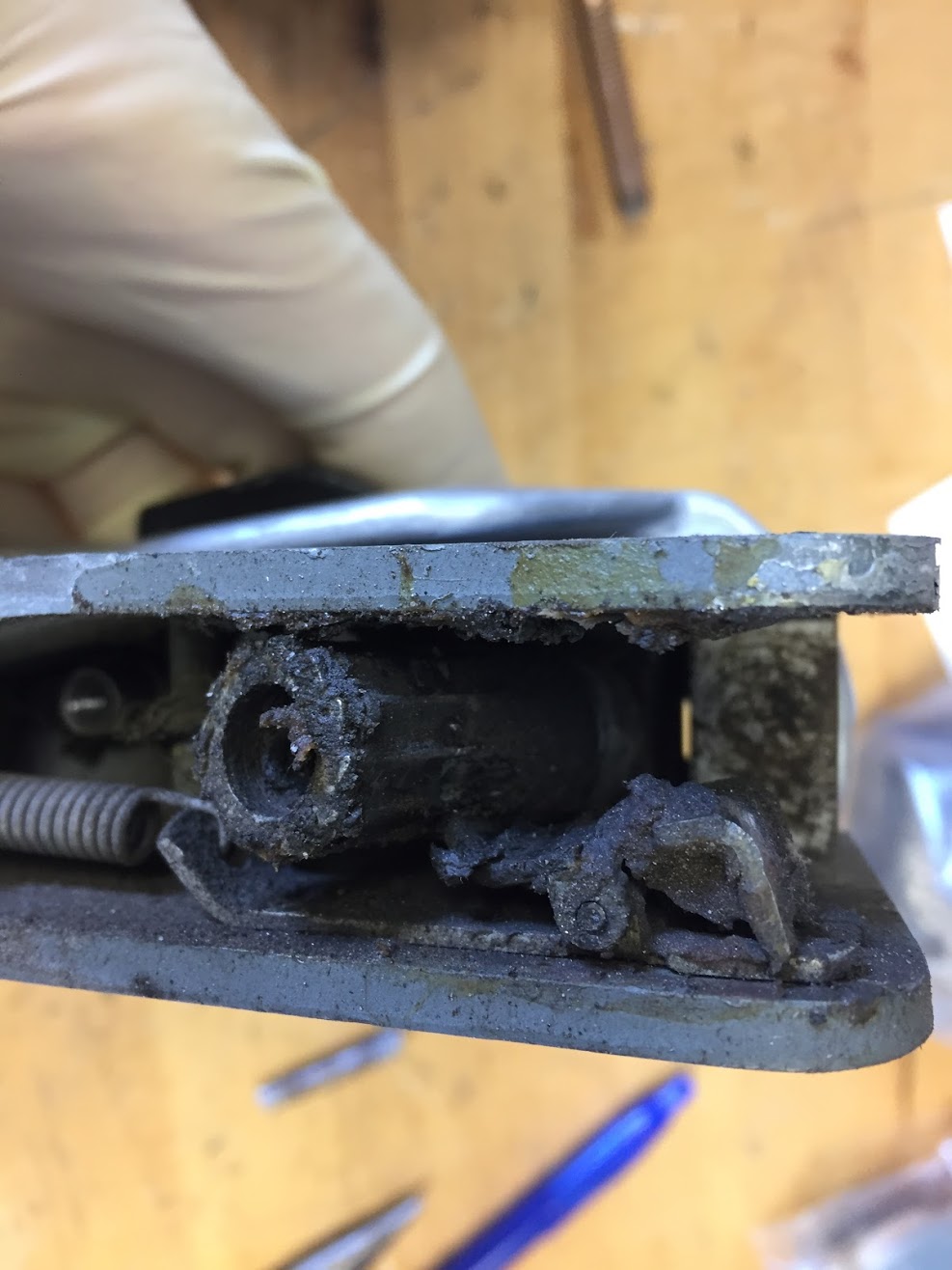
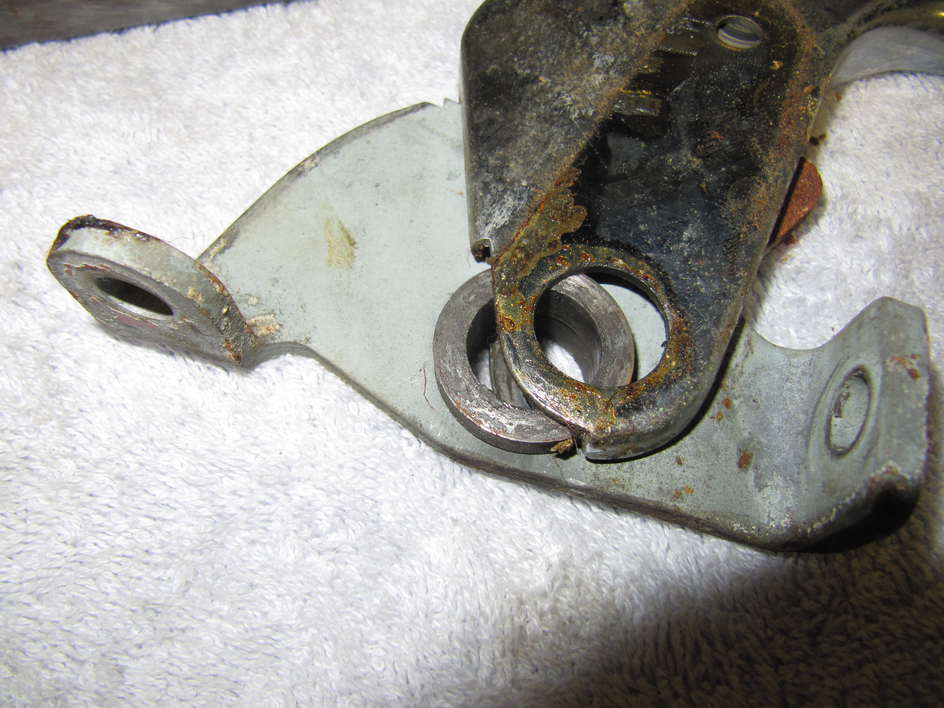
Handbrake Ratchet Nut and Spring Clip
The parts were working properly but did not rotate smoothly. I cleaned the components and applied some new grease for lubrication and reassembled the adjusting lever.
In rebuilding my handbrake units, I kept the old pivot bolts that hold the handbrake calipers to the primary caliper body, but I did install new retraction plates, tab washers, friction pads, and adjuster bolts.
Handbrake Schematic

- Handbrake Components

The Handbrake Compensator Lever is mounted to the rear axle case.

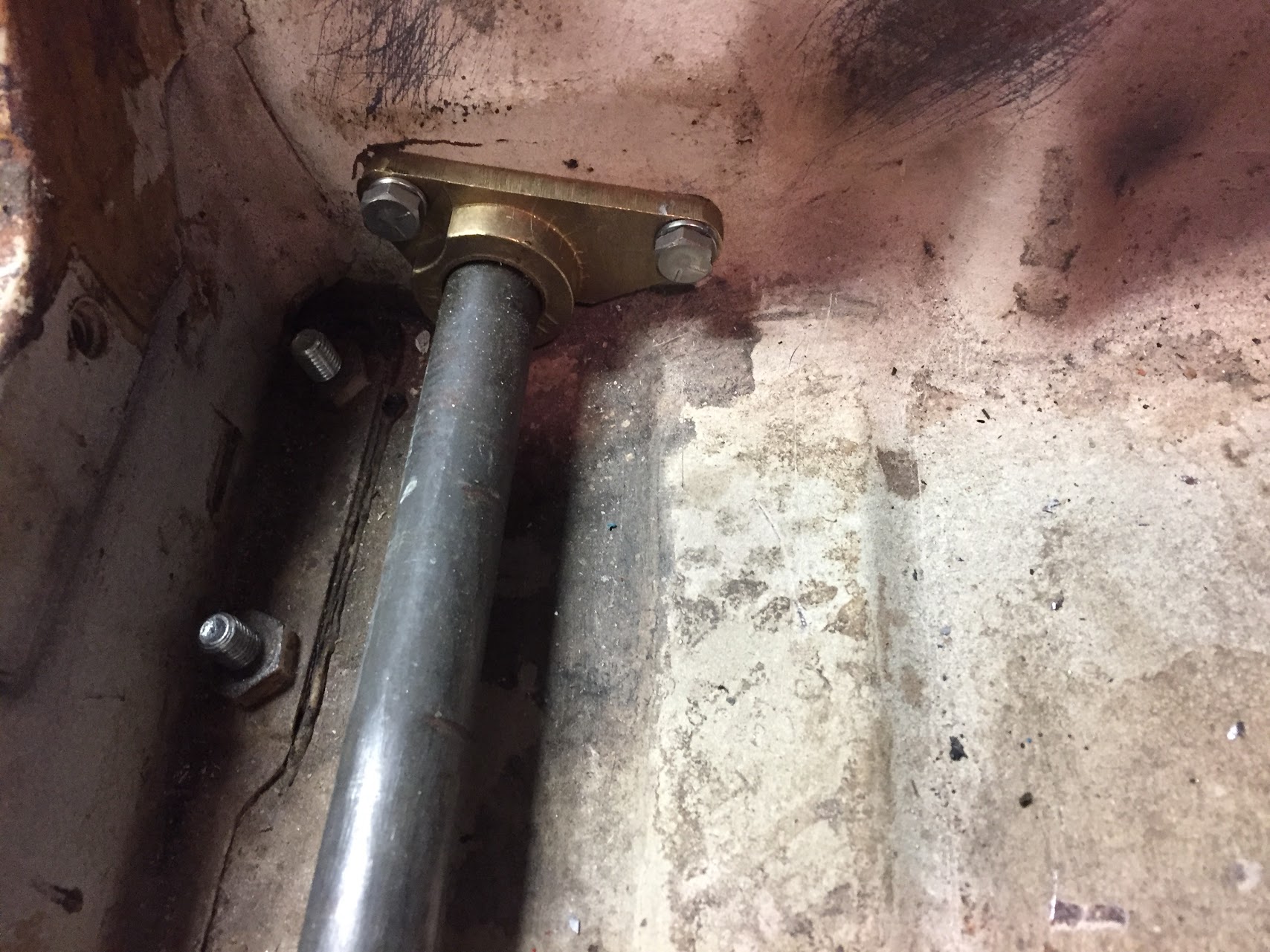
Housing for Handbrake Shaft
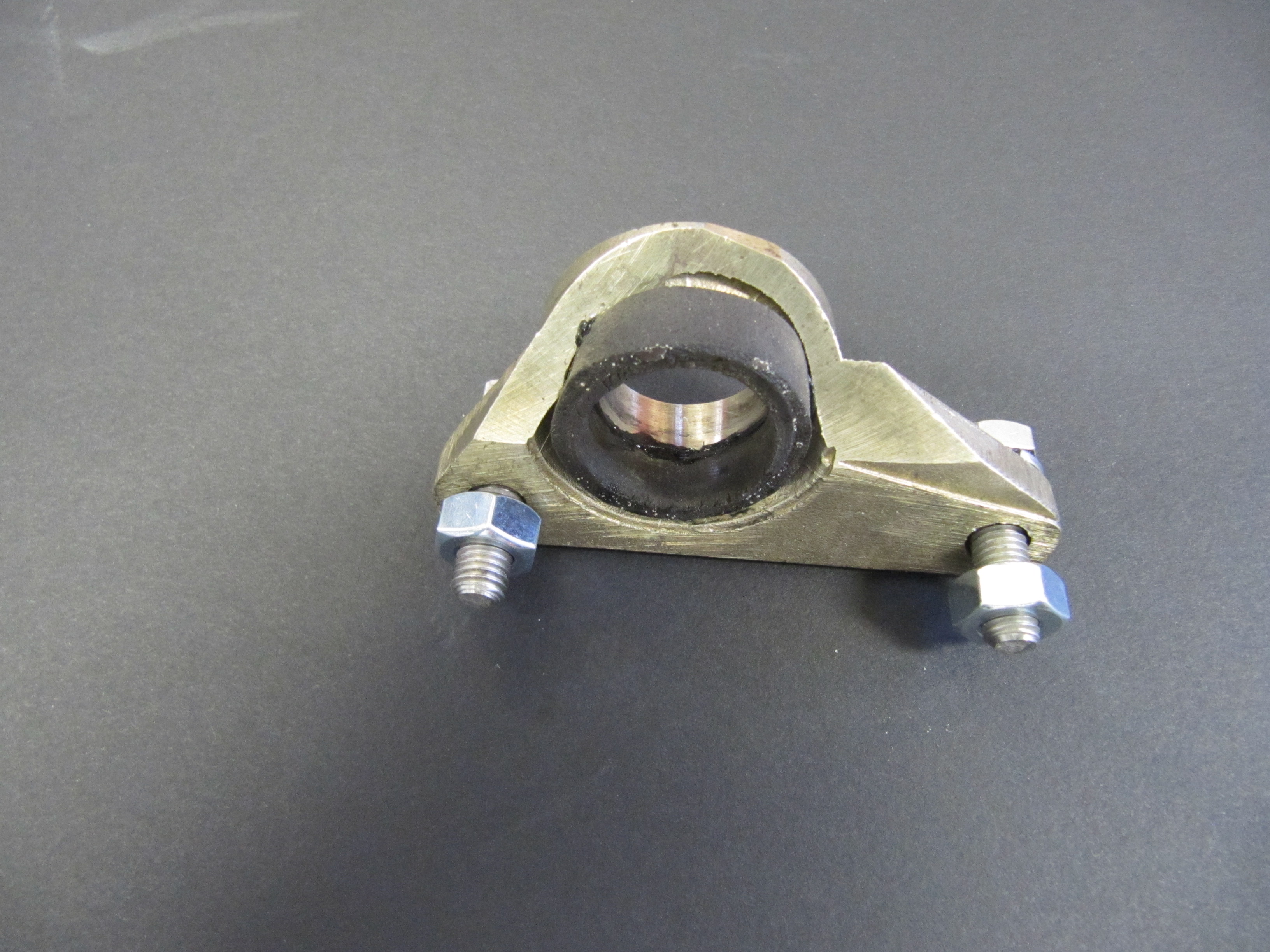
Housing for Handbrake Shaft
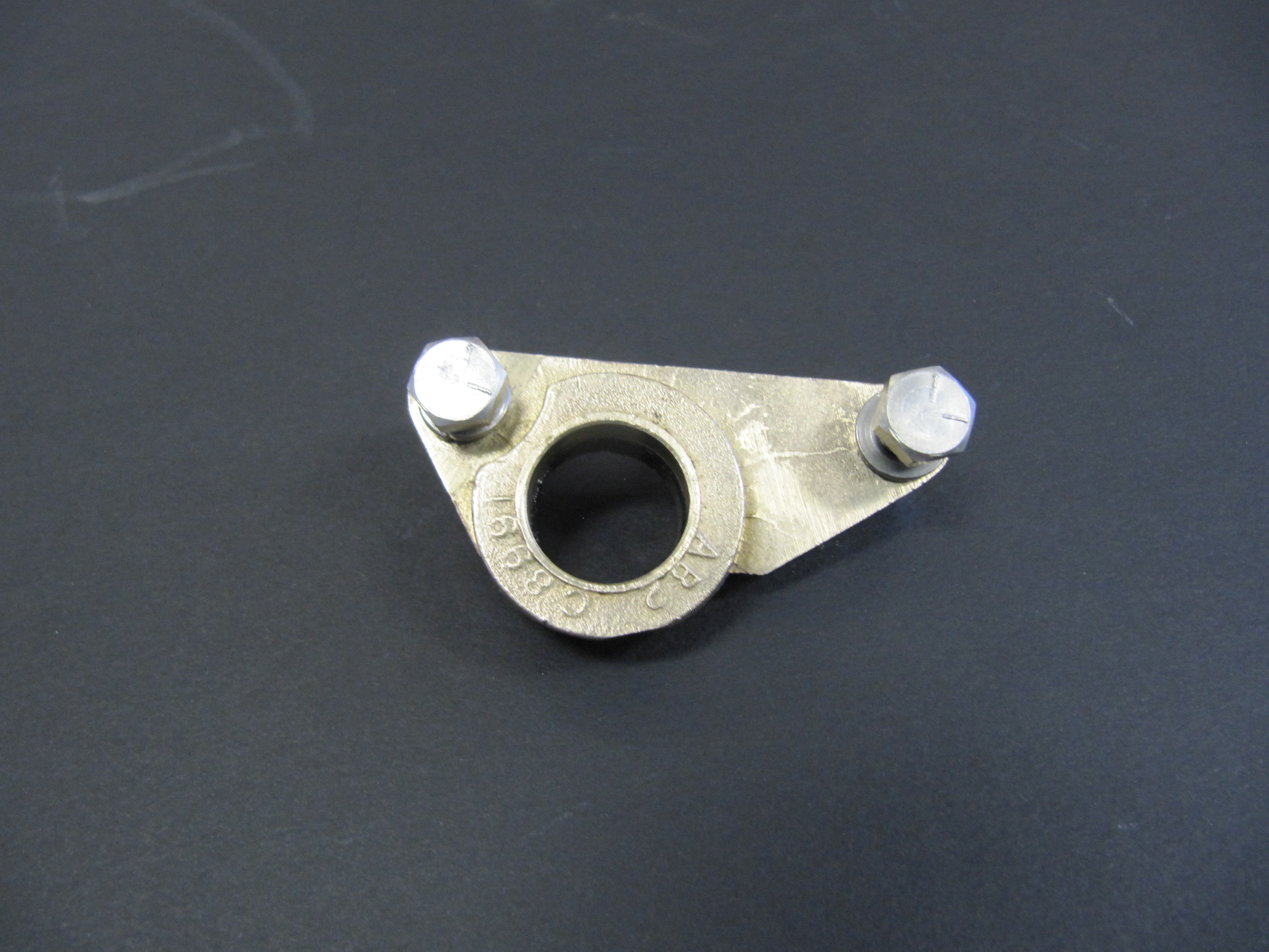
Housing for Handbrake Shaft
The housing is made of brass and has a rubber seal. It is mounted with two 1/4″ – 28 x 7/8″ hex head bolts with split washers. I cleaned up the housing and reglued the rubber seal.
Handbrake Compensator Lever

- Handbrake Compensator


- Handbrake Compensator

The Handbrake Compensator Lever assembly was a greasy and dirty mess, but I eventually got it cleaned up with the preloaded tension set. This was the “Before” as mounted to the rear axle differential:

Handbrake Compensator Assembly
Handbrake Cable Support Bracket
The primary handbrake cable is supported by a bracket that is pop riveted to the underside of the floorboard. It consists of a thin metal strip with a nylon guide through which the cable travels. the nylon guide is secured to the guide with two #10 – 32 x 7/8″ bolts, flat washers and nylock nuts.

Supporting Bracket for Handbrake Cable

Supporting Bracket for Handbrake Cable
Handbrake Cables
The Handbrake cables were greasy and dirty, but otherwise appeared serviceable, but I decided to go ahead and replace them with cables sourced fromSNGBarratt.

Handbrake Cables and Components
Handbrake Lever
The Handbrake Lever from the shaft to the primary cable was cleaned up and painted with POR-15. The clamping bolt to the shaft is a 5/16″ -24 x 7/8″ hex head bolt with a split washer.

Handbrake lever from Shaft to Primary Cable
The Fork End of the Primary Cable
The Fork End at the Rear of the Primary cable was also cleaned and painted to use with a new primary cable.

Fork End at Rear of Primary Handbrake Cable
Handbrake Lever/Handle Assembly
Disassembling, cleaning, and reassembling the handbrake assembly was fairly simple and straightforward. I have not, as yet, been able to source new components for the assembly such as the spring, button and small pin that hold the pin to the internal rod. Until I do, I have chosen to not completely disassemble the handle. I would like to do so to have it rechromed, but it is not in terrible shape. We will see what materializes.

Handbrake Assembly Components
The pawl was a little rusty which I cleaned with the media blaster. I will definitiely send it away to have it re-zinced.
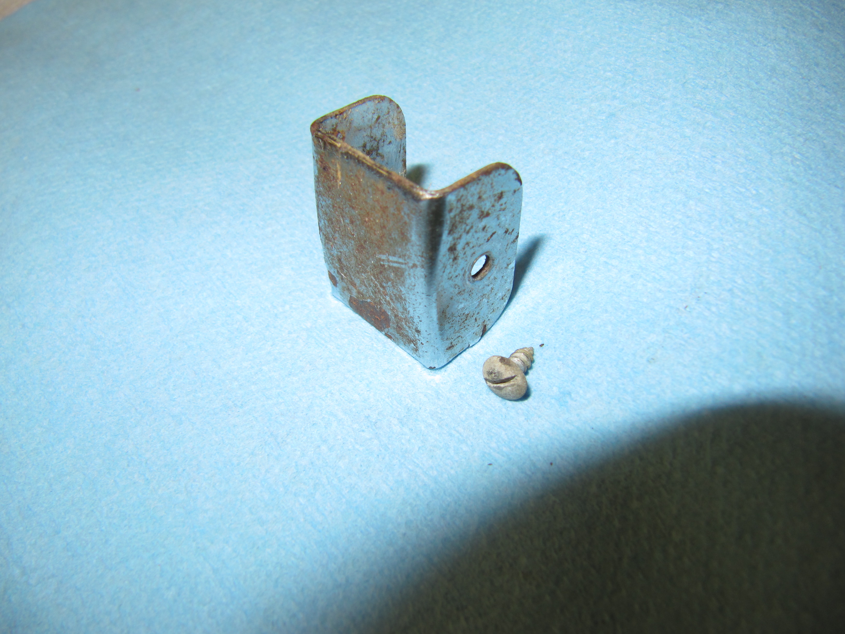
I first removed the cover plate, exposing handbrake pawl. This little piece was very rusty and it must be rechromed. It is held to the handle with two small self tapping screws that appear to be #2 x 1/4″. one of the screws was missing.

Cover Plate
Cover Plate
I then removed the chrome hex head bolt that held the handle, spring mechanism, pawl, the bracket operating the handbrake warning light switch and the shaft together. This was achieved by loosening the nylock nut. The bolt is a 5/16″ x 1 1/2″ special purpose bolt.
Brake Shaft

Handbrake Assembly Chrome Hex Bolt
Handbrake Assembly Chrome Hex Bolt Removed

Chrome Hex Bolt, Nylock Nut, Bracket Operating Handbrake Warning Light Switch
For lack of a better term, the pawl has two bushings with shoulders through which the handbrake shaft passes. These will be reused.

Pawl Bushings

Pawl Bushings
Pawl Bushings
Handbrake Warning Lamp
The MK2 has a warning light for handbrake activation. The Switch, At Base Of Handbrake Lever, Operating Handbrake Warning Lamp is mounted to the interior floor with a Bracket. I am replacing the switch itself with a new component. The switch is held to the bracket with two adjusting nuts. The bracket is mounted to the interior floor with two #10-32 x 1/2 cheese head machine screws and lock washers.
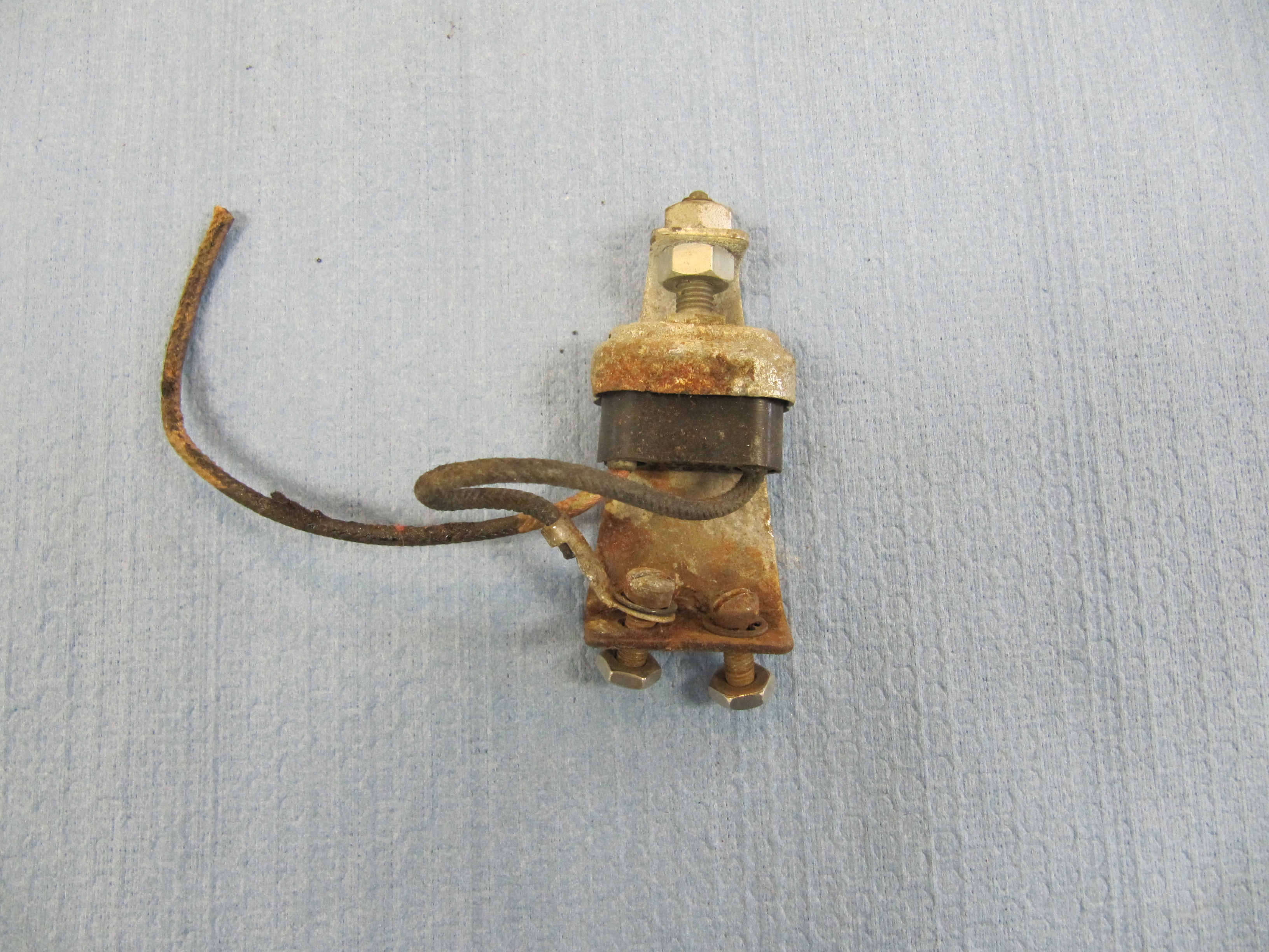
Handbrake Warning Lamp Mounting Bracket and Switch
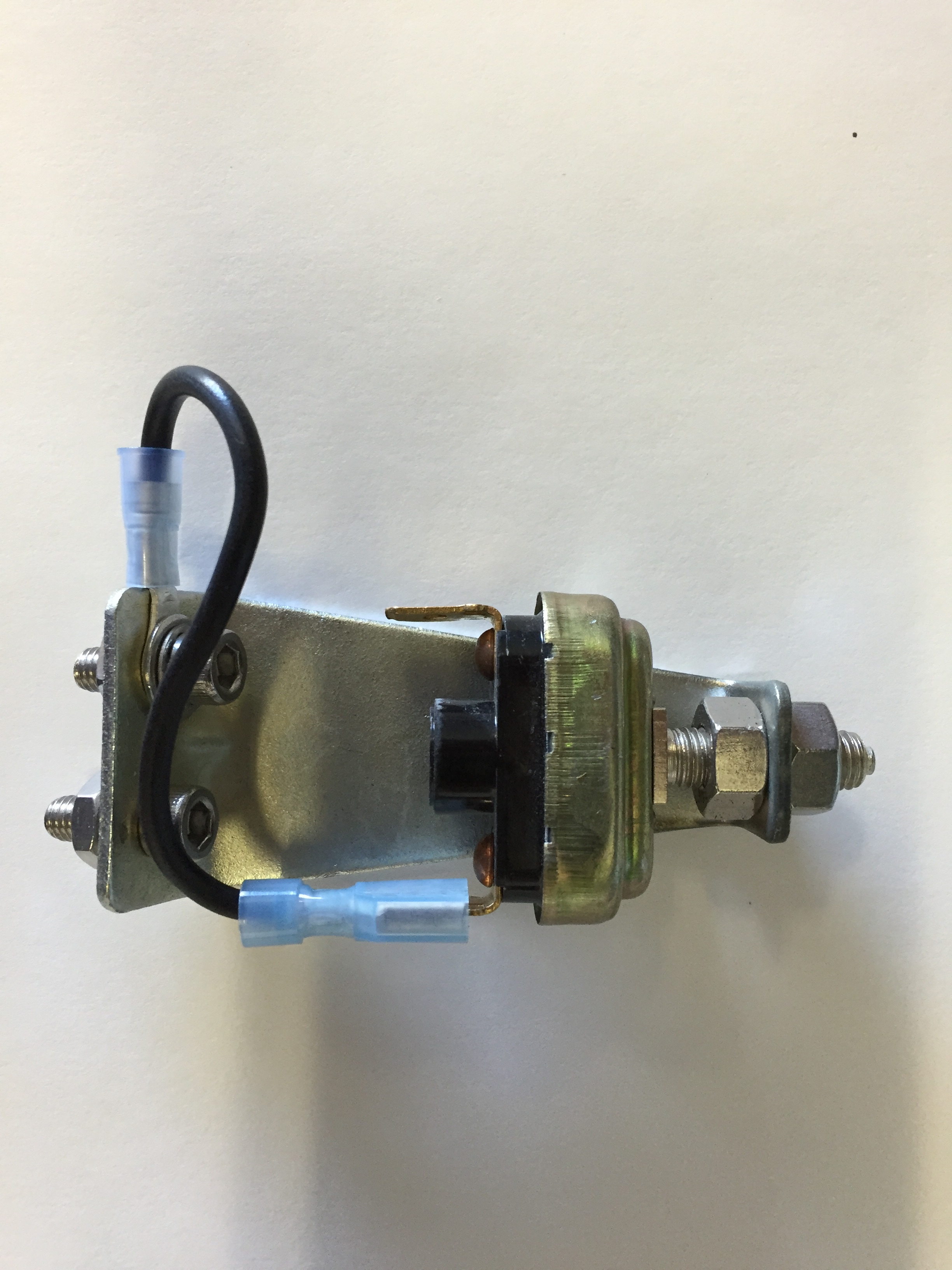
Handbrake Warning Switch
I media blasted the bracket and zinc plated it for and reuse.
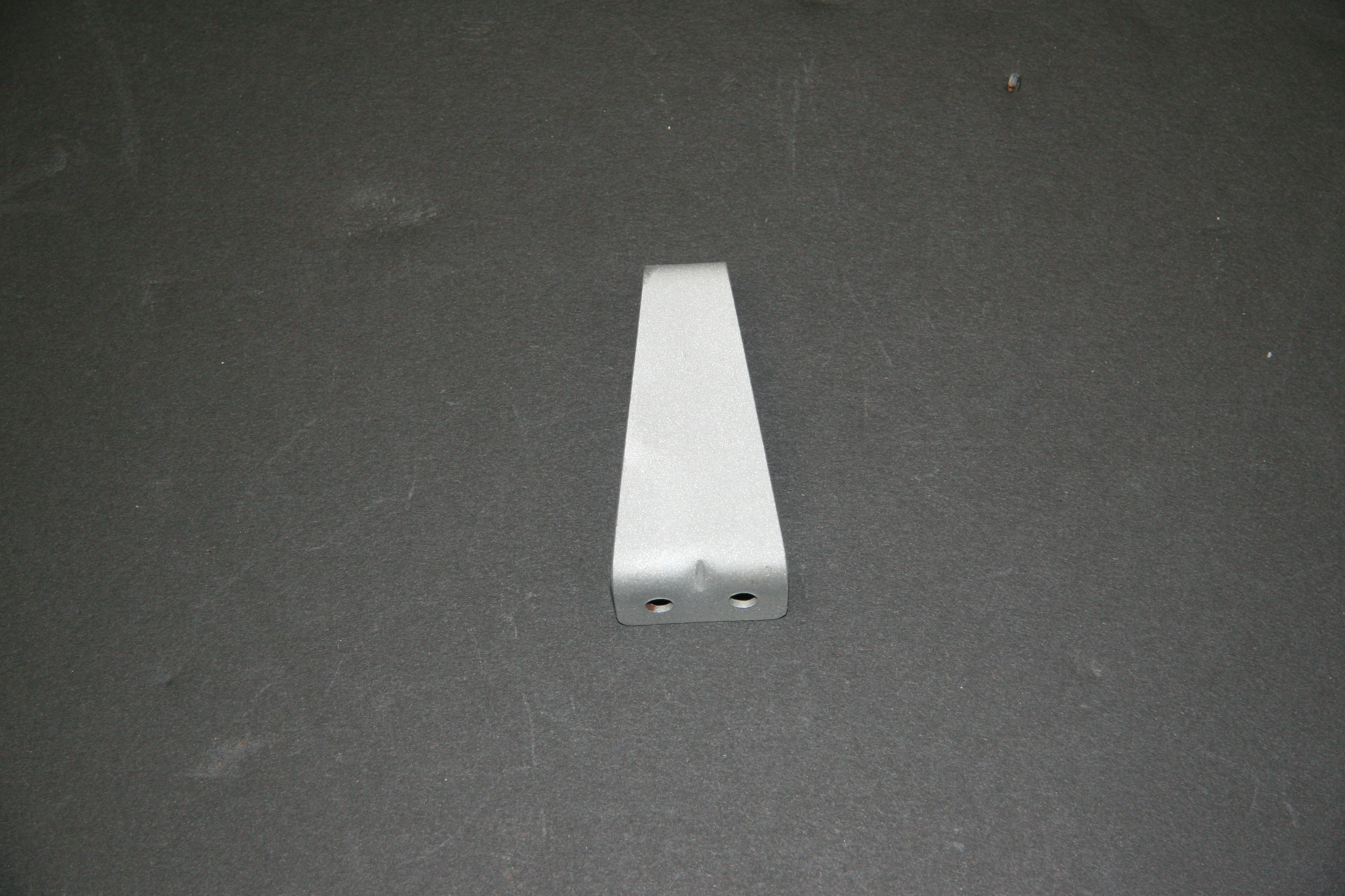
Handbrake Warning Lamp Switch Mounting Bracket
Handbrake System Installation
I began the installation by attaching the LH and RH compensator-to-caliper cables to the compensator. I used new cables sourced from SNG Barratt. The fork ends at one end of the cable are attached to the compensator balance lever with clevis and split pins as are the other ends to the handbrake calipers.
Handbrake Compensator Assembly with Cables
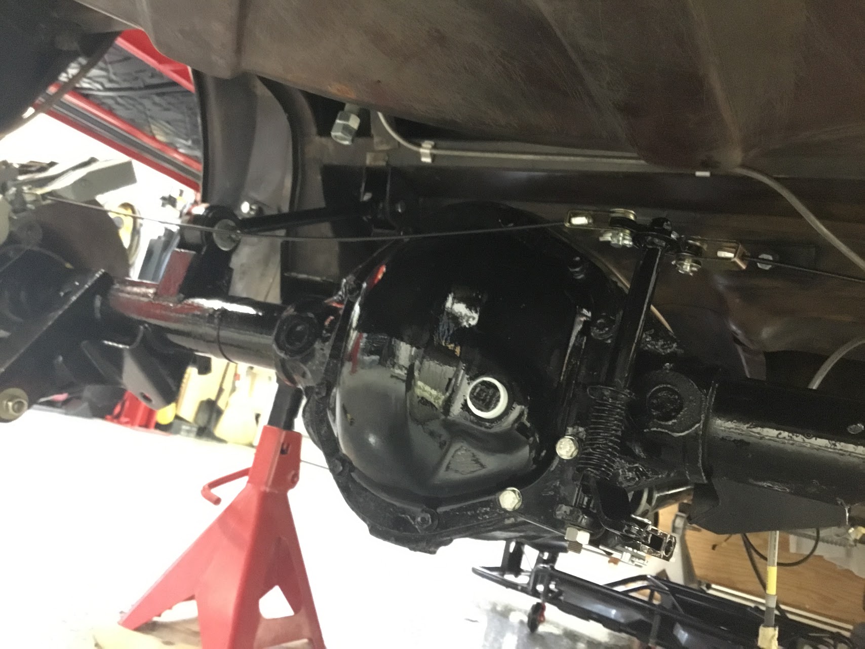
I then secured the pre-assembled handbrake compensator assembly to the rear axle. Two 5/16″-24 x 3/4″ hex head bolts with split washers are used to attach the assembly to the rear axle carrier through its cover. Note: These are coarse thread bolts, not fine thread as is typically used throughout the car! These two bolts are 1/4″ longer than the other cover mounting bolts to allow for the width of the compensator bracket. Sorry for the dark photo. It is a challenge to get contrast when everything is black.
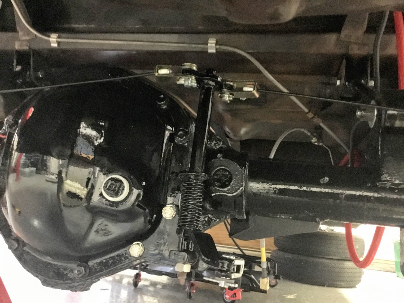
Handbrake Compensator Assembly Mounted

RH Handbrake Cable from Compensator to Caliper
LH Handbrake Cable from Compensator to Caliper
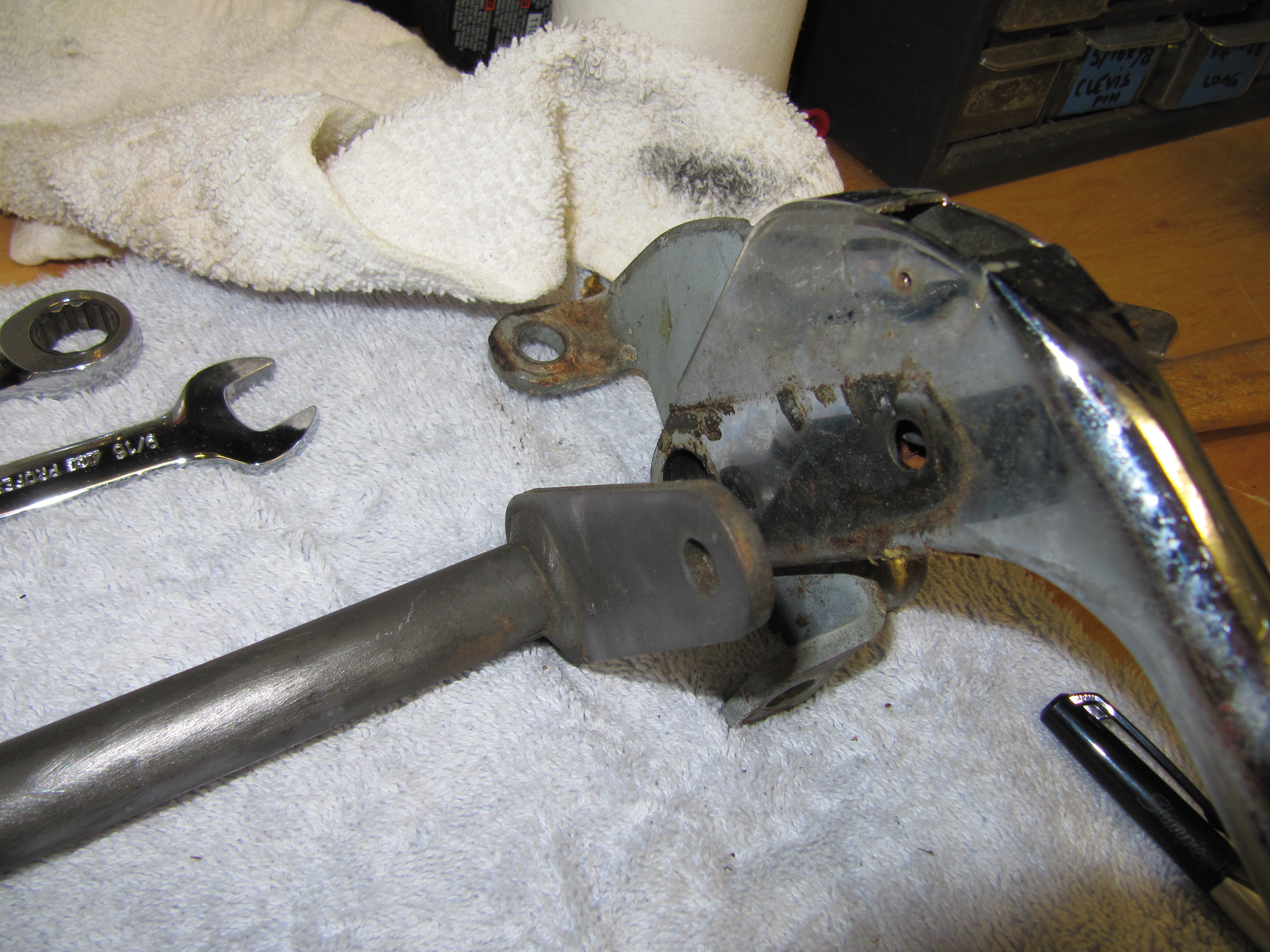
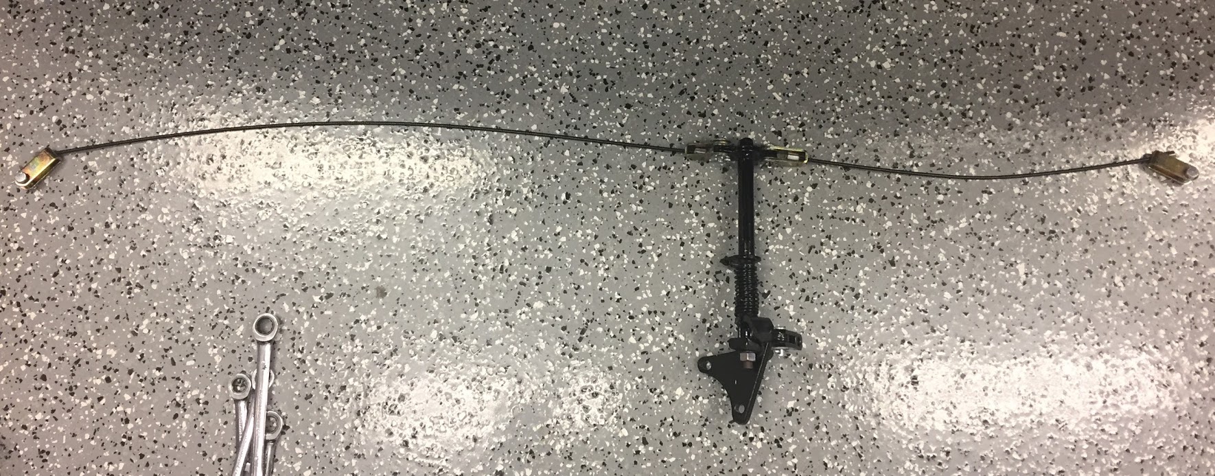
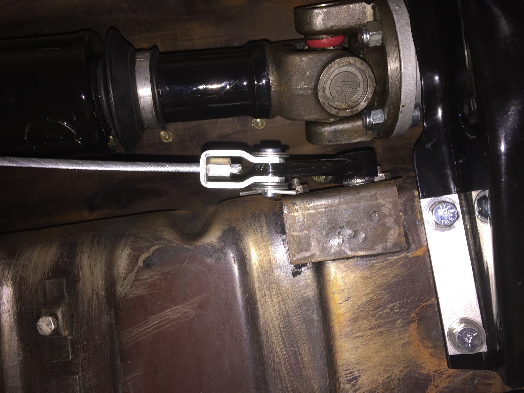
I then prepared the primary cable that runs from the handbrake shaft lever to the compensator. There is a fork end at the rear end of the primary cable that permits adjustment of cable tension. A universal jaw is then used to connect the fork and the compensator, locked in place with a clevis and split pin. I went ahead and connected the jaw end to the compensator.
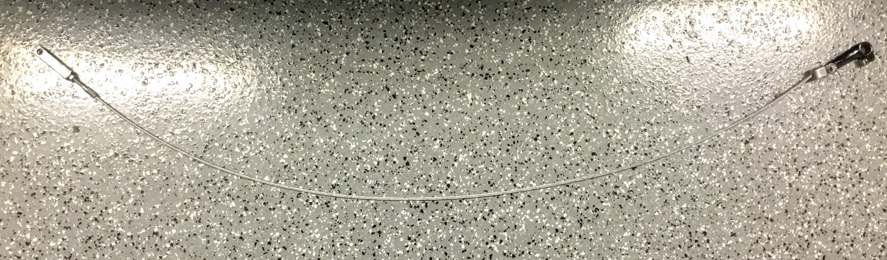
Primary Cable from Lever to Compensator Assembly
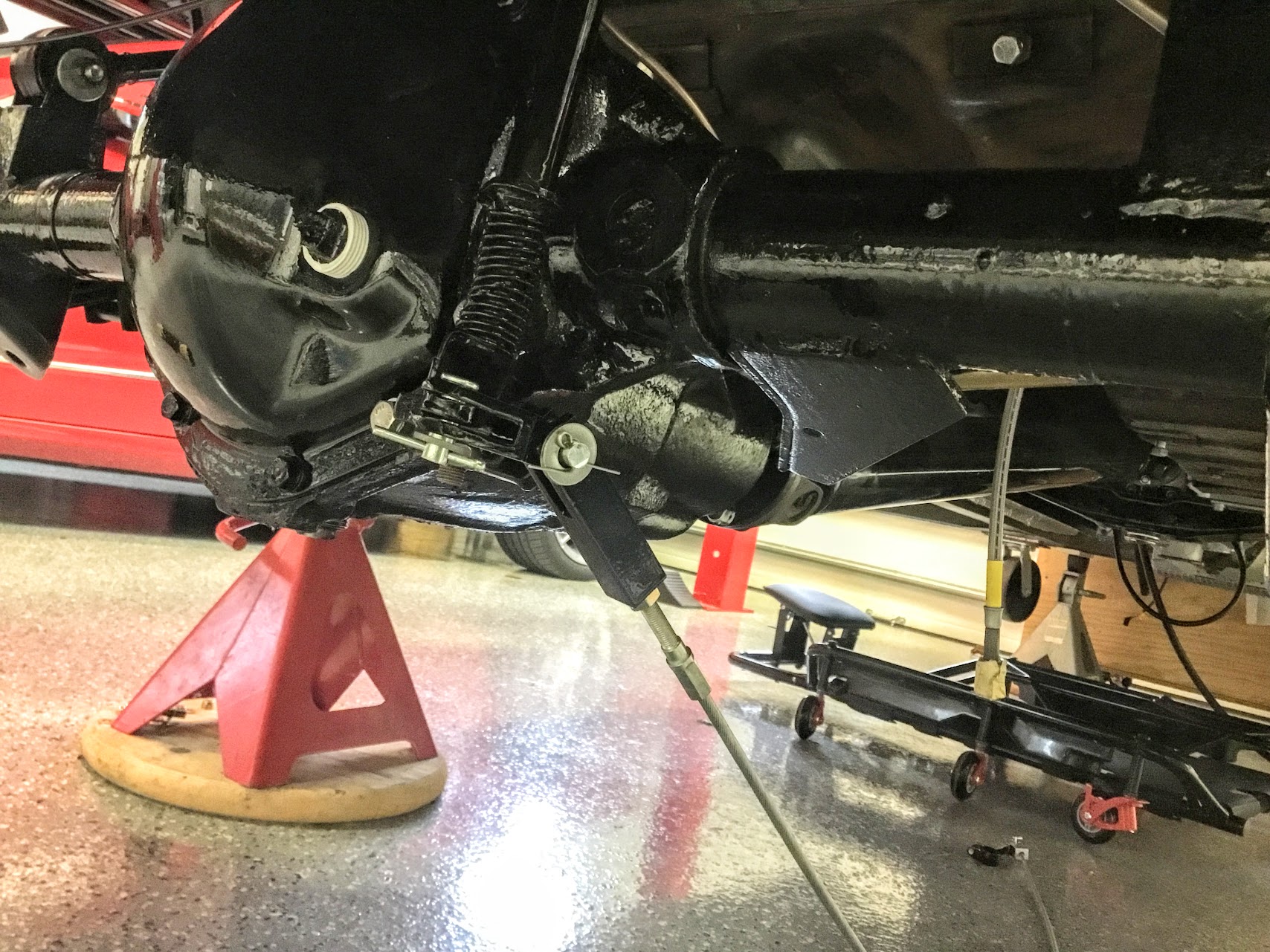
Primary Cable from Lever to Compensator Assembly Mounted
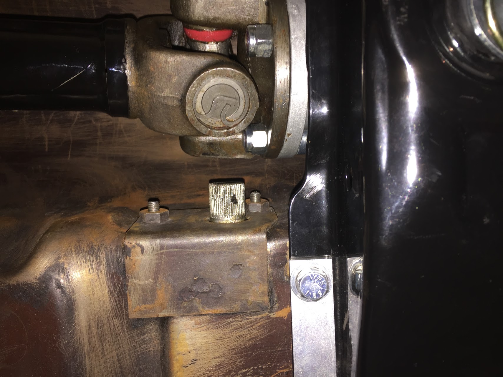
The next step was to attach the housing for the handbrake shaft with its rubber seal to the propshaft tunnel. The housing is secured to the tunnel with two 1/4″-28 x 5/8″ hex head bolts into captive nuts on the inside of the tunnel.
Handbrake Shaft Housing
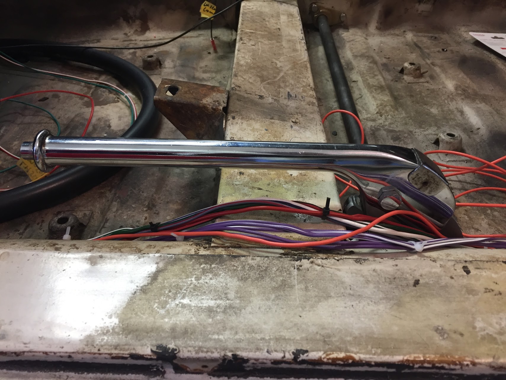
One can then insert the splined end of the shaft through the housing.
Handbrake Shaft Splined End
The handle end of the handbrake shaft is attached to the car floor and seat mounting crossmember with two bolts. The crossmember hex head bolt is 3/8″-24 x 3/4″ with a flat and split washer. The floorboard hex head bolt is 3/8″-24 x 1″. It goes through the mounting bracket and floor and is secured with a flat washer, and nylock nut. I found it easiest to install the handbrake first and then to install the handbrake warning light switch to the floor with the #10 machine screws. The seat crossmember bolt should be started initially and then the floor mount bolt.

Handbrake front mount bolt to seat crossmember
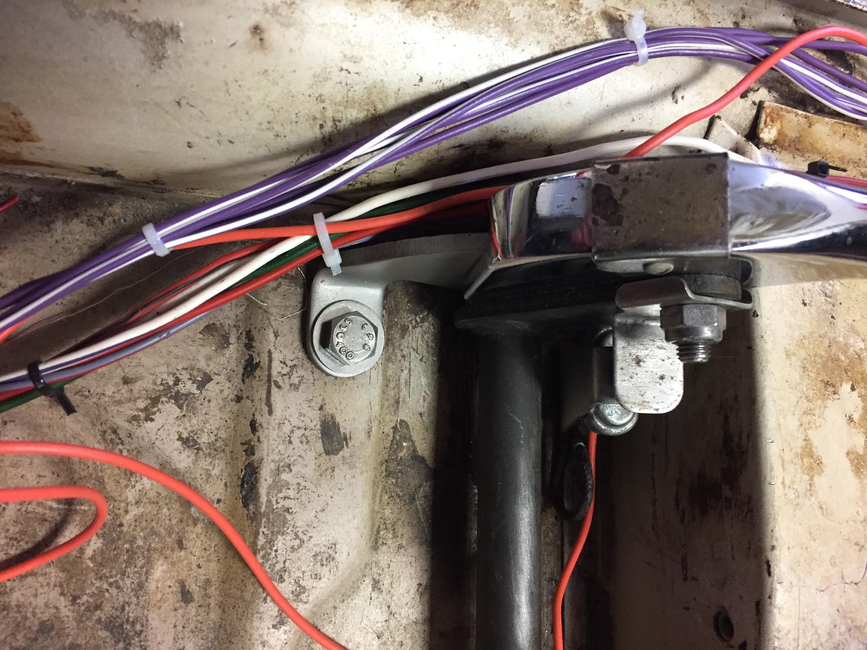
Handbrake Floor Mount Bolt through Floor
The handbrake warning light switch is depressed when the handbrake is not on. When the handbrake handle is pulled upward the switch is activated and the warning light illuminates.
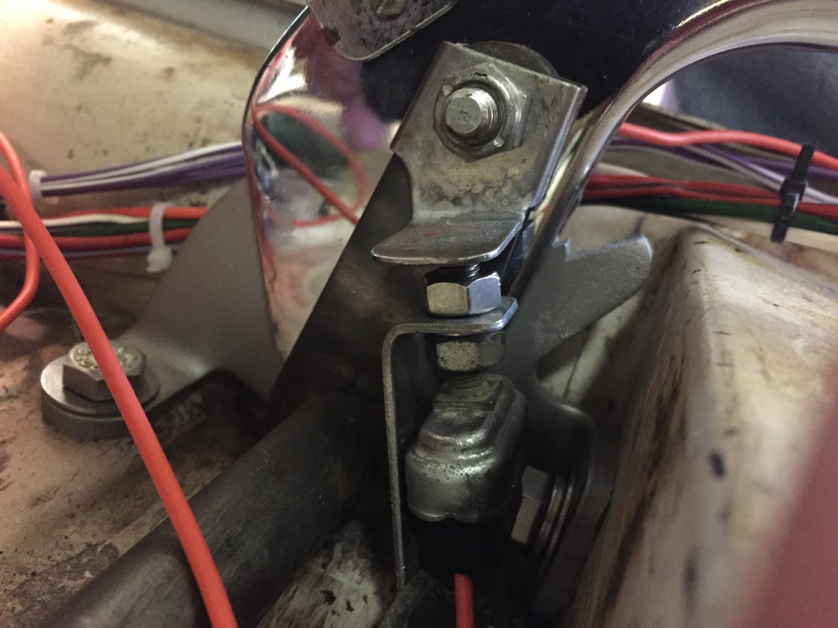
Handbrake Warning Switch
Handbrake Warning Switch
Handbrake Assembly Installed
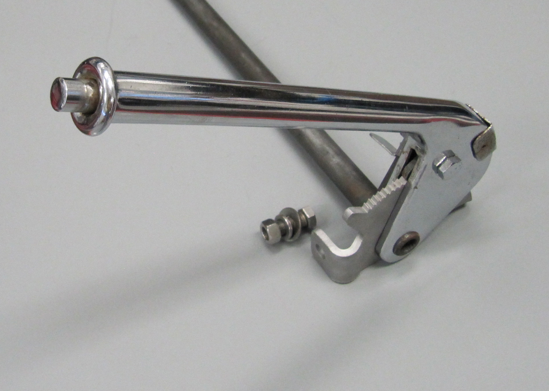
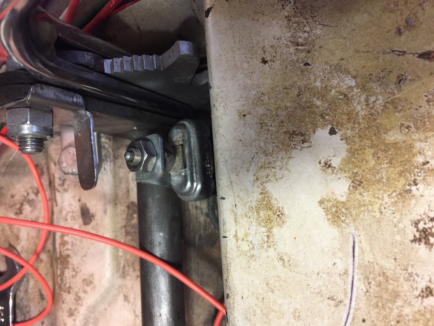
The handbrake lever previously mounted to the forward end of the primary cable was then slipped onto the splined handbrake shaft and the 1/4″-28 x 3/4″ hex head bolt was tightened to secure the lever to the shaft.
Handbrake Lever Attached to Shaft
To keep the primary cable from fouling against the propshaft, Jaguar installed a supporting bracket that is pop riveted to the floor. Since I will be dismantling everything before painting, I used #6 machine screws to temporarily mount the support bracket to the underside of the body.
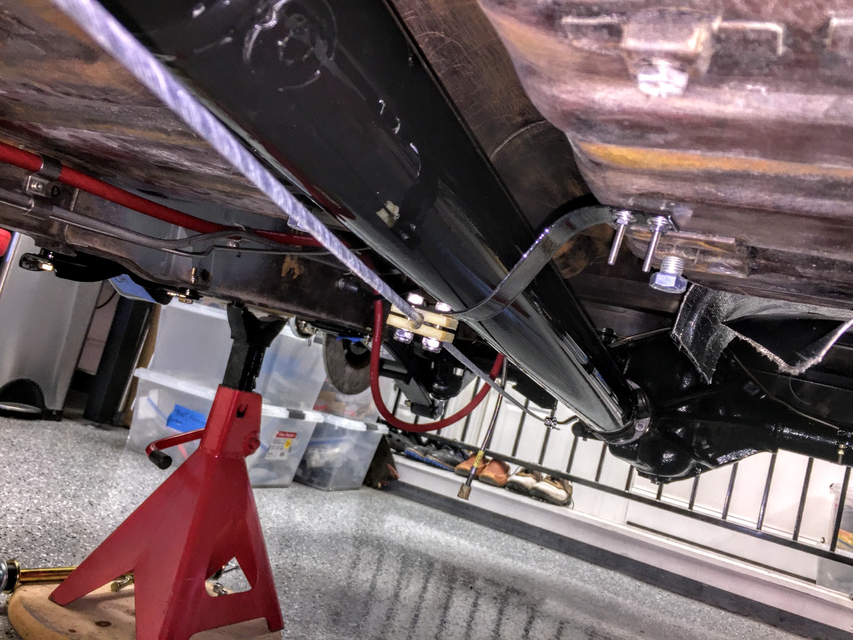
Handbrake Cable Support Bracket Mounted
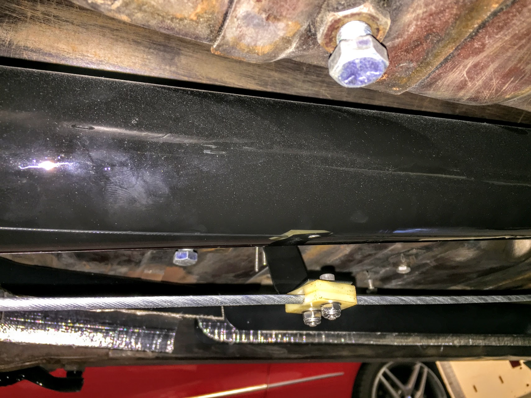
Handbrake Cable Support Bracket Mounted
With the exception of final adjustment of the primary cable to achieve the proper tension, that completes the mounting of the handbrake system to the car.
Refitting the Handbrake Caliper Mechanism
I just followed the Service Manual instructions for refitting the handbrake calipers and friction pads. Although, as with most things, it is not quite as easy as it reads! With the handbrake caliper assembly in your hand (friction pads installed), the adjusting bolt is screwed into the ratchet nut until their is a distance of approximately 7/16″ between the friction pads, that is, the thickness of the disc plus 1/16. The split pin is then refit through the handbrake caliper friction pad carrier and the adjuster bolt to hold it in place. The entire unit is then “dropped” over the disc rotor and in place on the primary brake caliper. The two pivot pins, retraction plates and tab washers are then installed. Yes, it can be a pain to get these pins aligned.
The directions indicate that one is to pull and release the operating lever at the caliper repeatedly when the ratchet will be heard to “click over.” This operation is repeated until the ratchet will not operate which will indicate that the correct clearance is maintained between the disc and the friction pads.
I then connected the cross cables with their clevis pins. With the handbrake lever in the full down (slack) position, I loosened the lock nut at the rear end of the main cable and then “adjusted the length of the main cable by screwing the threaded end of the cable into the fork end to a point just short of where the handbrake operating levers at the calipers start to move.” The cables will have some slack in them when the handbrake lever is in the rest position.
I then tested the handbrake lever and found that I “locked-up” the rear brake rotors after six upward clicks n the handbrake pawl. I then made sure that I had all of the split pins installed and I declared the system functional!