
Body Panels and Trim
Cover and Blanking Plates
Of course, there are many large and small components that comprise the finished body of the MK2. The clean-up and preparation of the body and its primary parts is addressed in the “Body Prep” post. However, I have also begun to prepare some of the smaller components such as the covers or blanking plates for the firewall and under-dash interior of the car. The Jag was assembled for home and foreign markets so holes were located in the body superstructure to accommodate either LH or RH steering. Blanking plates were fastened over the holes not used. For example, the image below shows the Cover Plate Over Steering Column Cut-out on Centre Dash as well as the Headlamp Dipper Switch Blanking Plate. The Cover Plate for the Steering Column is pop riveted to the body from the interior side of the firewall, while the Dipper Switch Plate is secured from the engine side of the firewall with two #10″- 32 x 1/2″ hex head bolts, nuts and shakeproof washers. The nuts are located on the engine side of the firewall with bolt heads on the interior side. The image shows socket bolts, but they will be replaced.

Steering Wheel Shaft & Dip Switch Blanking Plates
In early July, 2014 I began trial fitting many components. This was motivated by the trial installation of the RetroAir air conditioning kit. The dip switch blanking plate hardly required trial fitting, but you have to start somewhere. I did not trial fit the Steering Wheel Blanking plate since it required riveting to install and I did not want to drill out the rivets again.
Dip Switch Blanking Plate Trial Fitting
Dip Switch Blanking Plate Trial Fitting – Interior View
I made a closed cell foam gasket for the steering column blanking plate and installed it in the firewall/floor with screws temporarily. I will rivet it to the firewall/floor after the body is painted.
Foam gasket for Steering column blanking plate

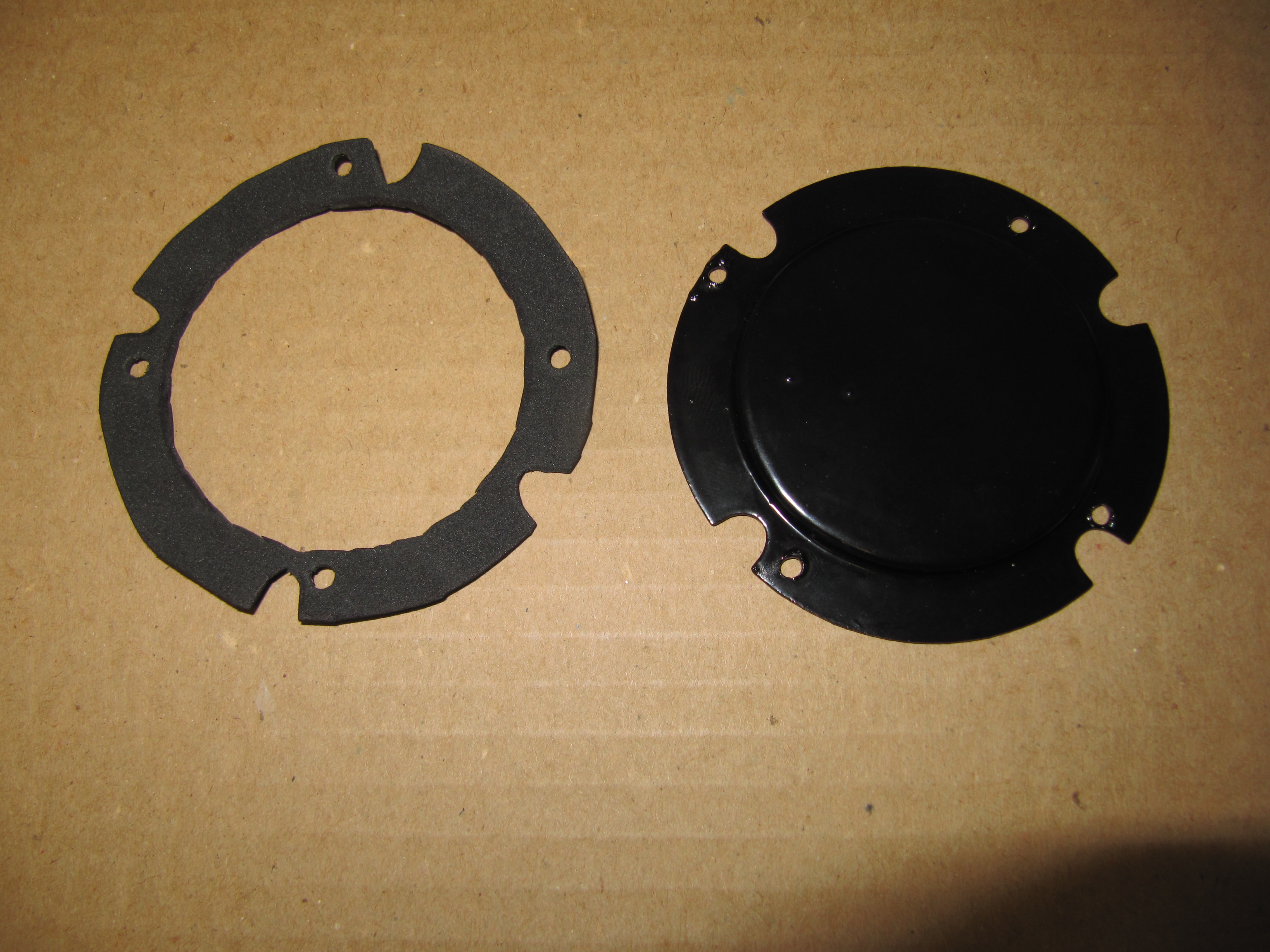
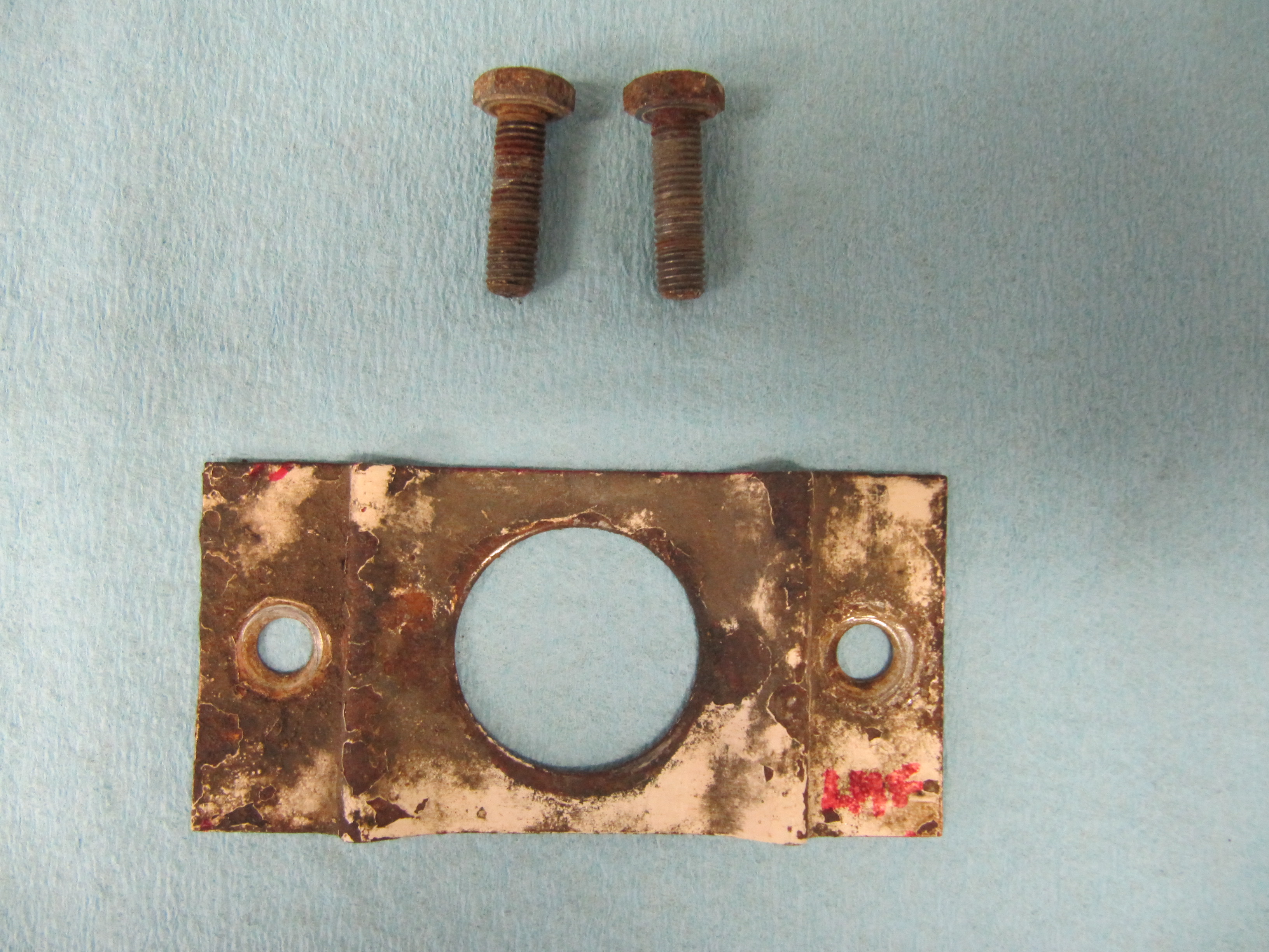
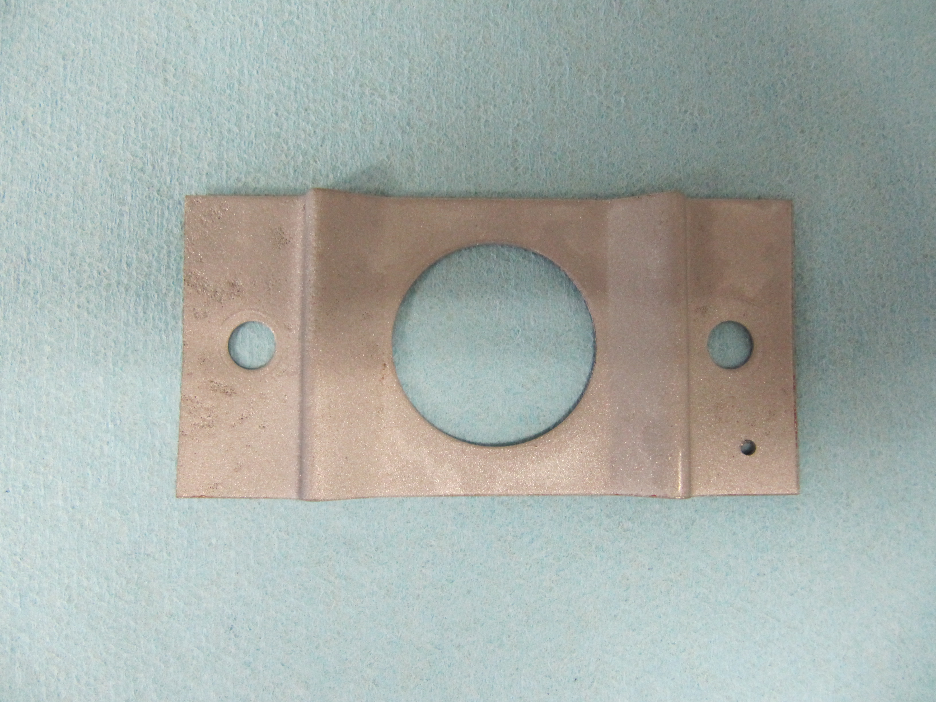
The Cover Plate Over Pedal Mounting Cut-out on Centre Dash
I will not be using the Cover Plate since I am air conditioning my car and the Blower mounts in this location with a new face plate.
The cover plate uses the same gasket as used on the master cylinder housing. It is secured to the firewall with four 1/4″ – 28 x 1/2″ hex head bolts with plane and shakeproof washers and 1/4″ -28 nuts.
Cover Plate Over Pedal Mounting Cut-out on Centre Dash
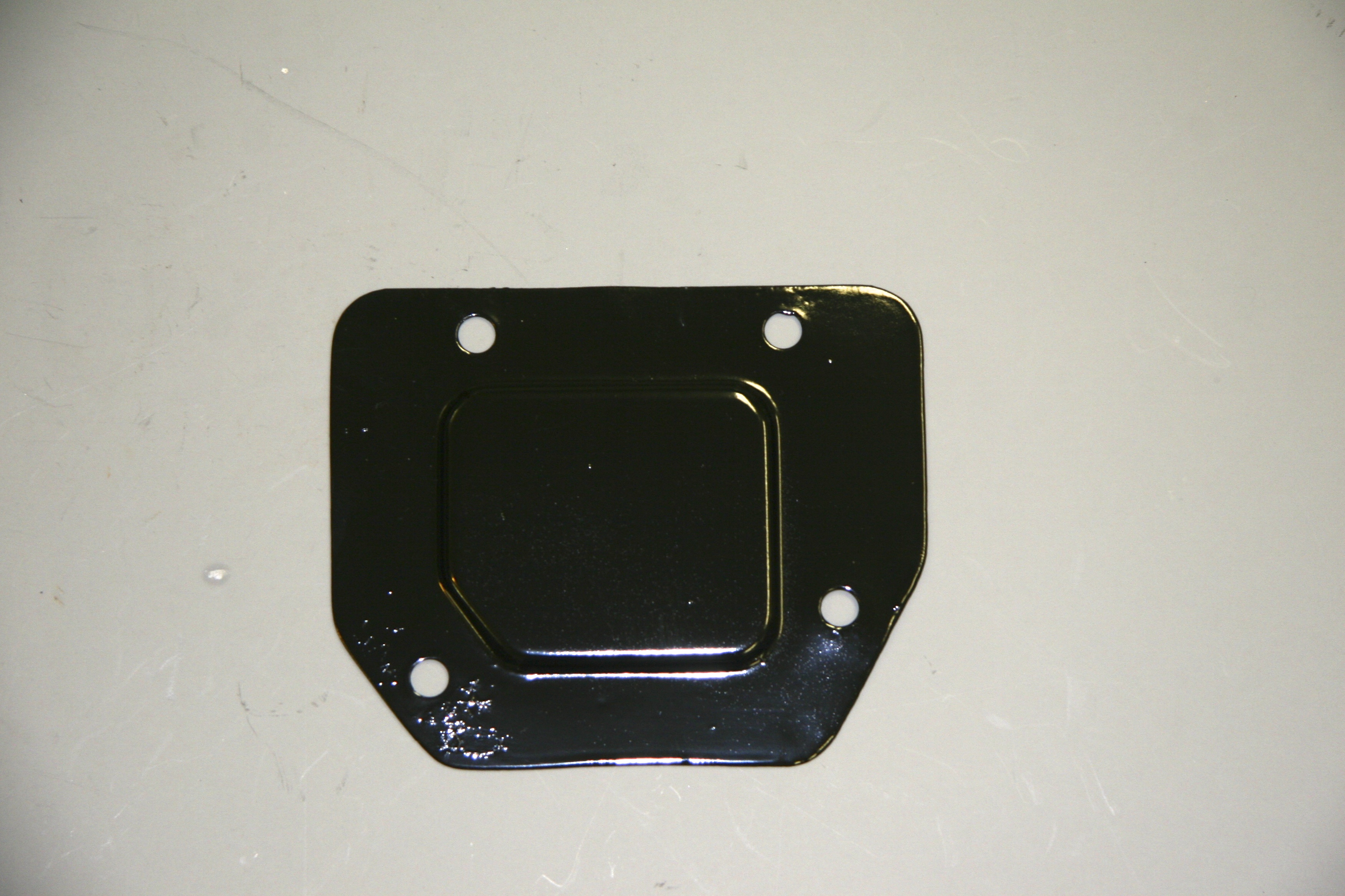
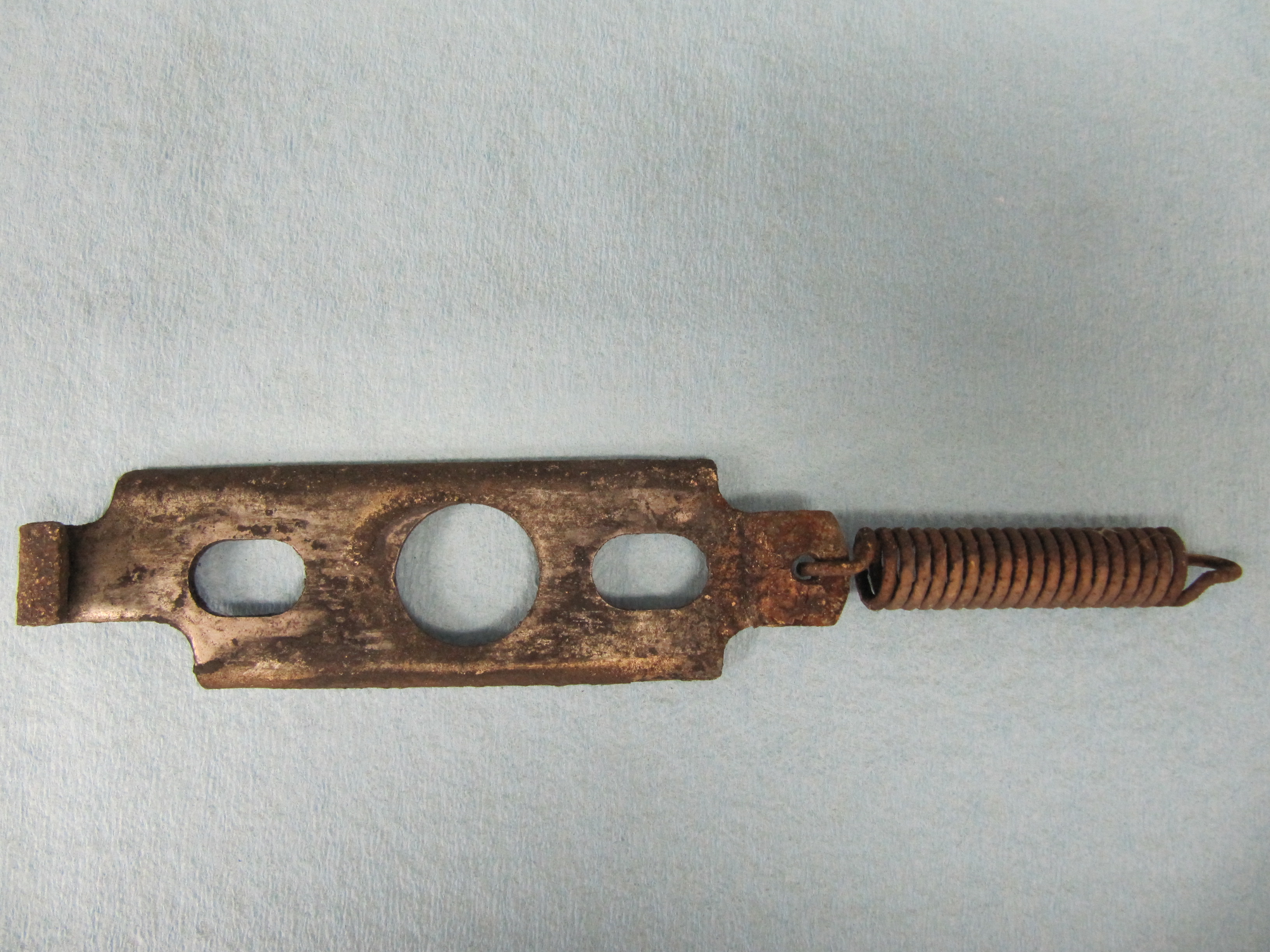
Striker Plate for Bonnet Catch
I media blasted the striker plate and will have it zinc plated. Not sure that it will matter, but I drilled a small hole in the left front corner (from the driver’s seat) to relocate the plate when the time comes. The plate is secured to the car and to the other catch components with two two 1/4″ – 28 x 3/4″ hex head bolts.
Striker Plate
Striker Plate Clean
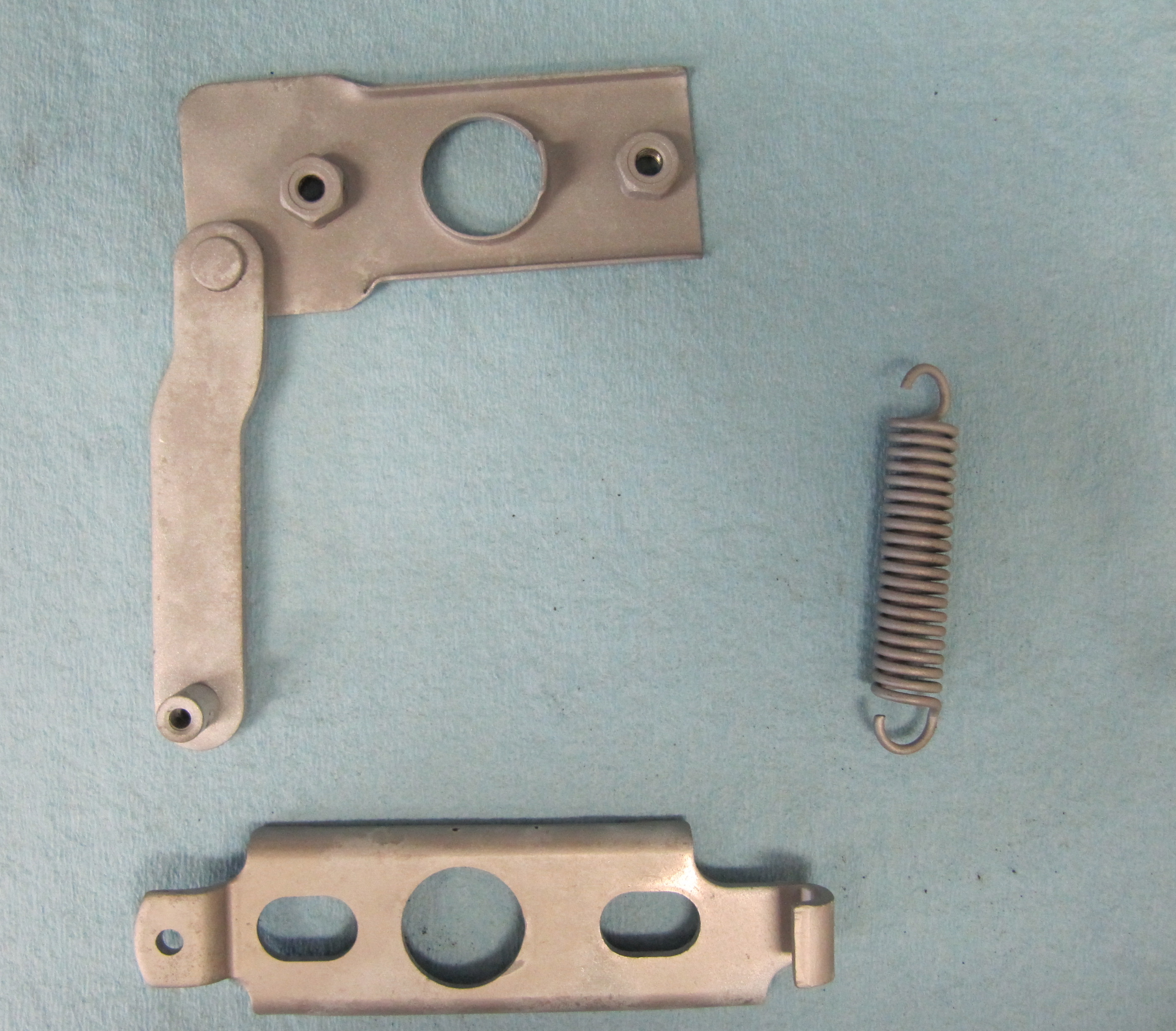
Bonnet Catch Base Plate, Catch Plate and Spring
These three pieces of the bonnet catch mechanism were media blasted and will be zinc plated.
Bonnet Catch Components
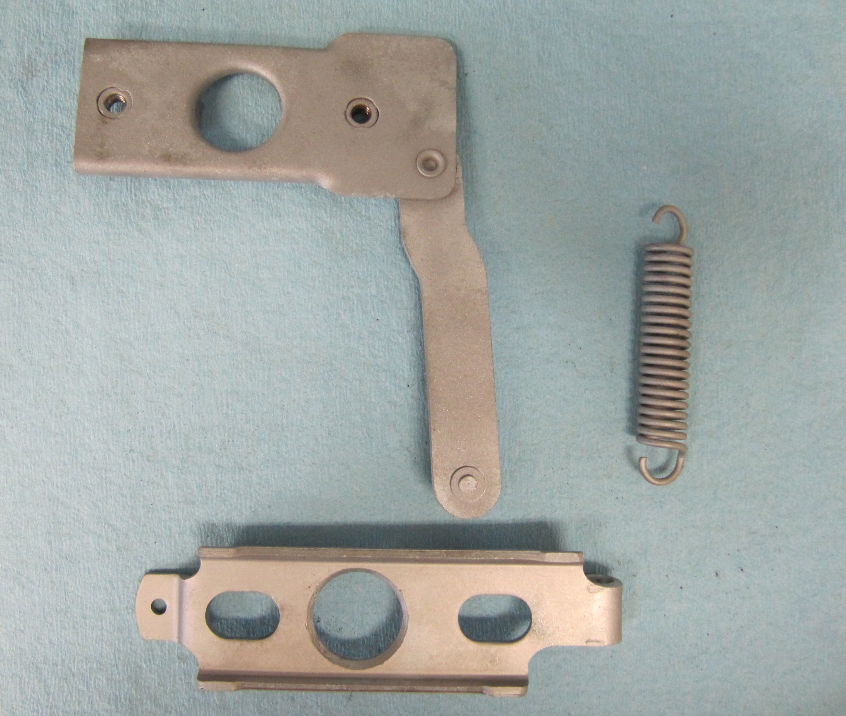
Bonnet Catch Components
Bonnet Catch Components
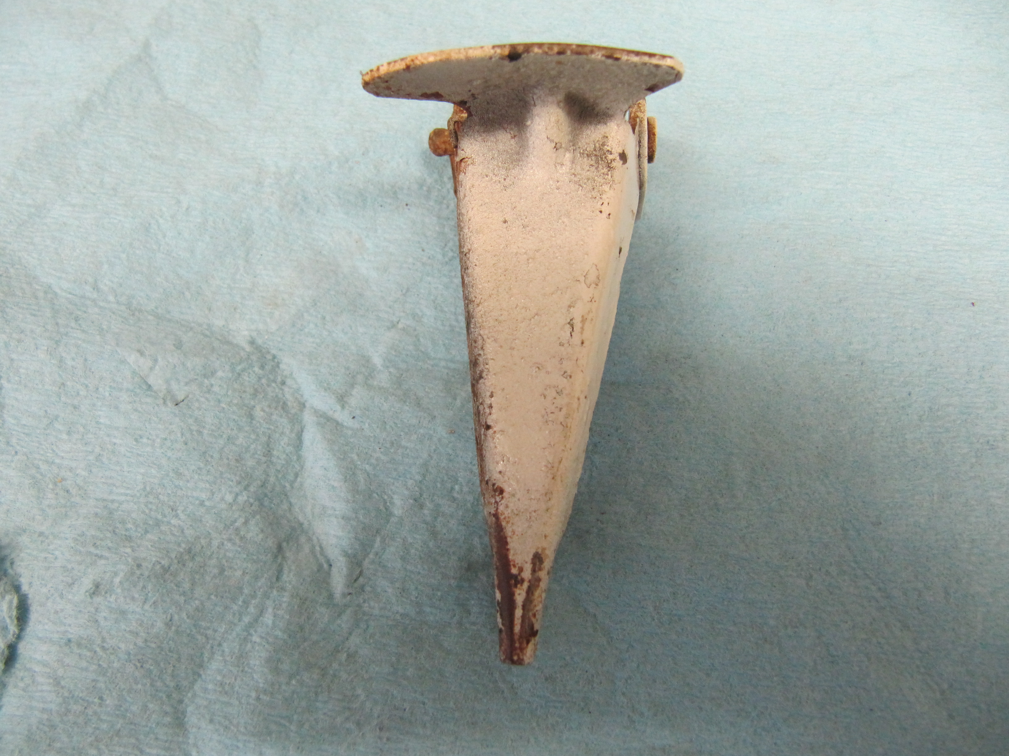
Bonnet Striker & Pin
This assembly consists of the striker pin or peg, three retaining washers, a spring, and a nut to adjust the compression of the spring. The assembly mounts to the bonnet with the threaded end of the peg which is 7/16″ – 20. The large washer was bent and I don’t know if that is intentional or not. I could not find new components from the usual vendors so I blasted these pieces and painted them with POR-15 to prevent future rusting.

Bonnet Striker Pin Assembly
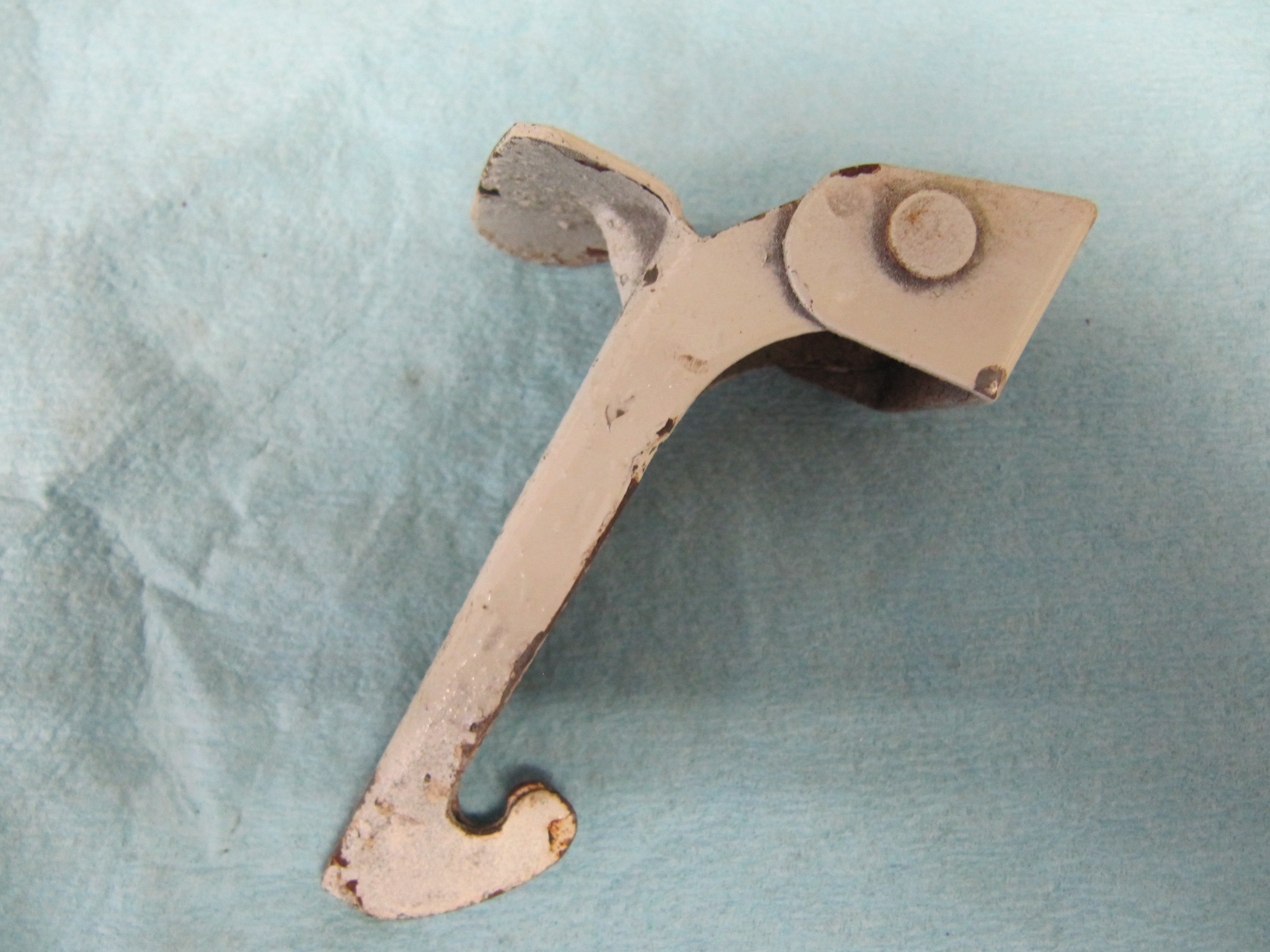
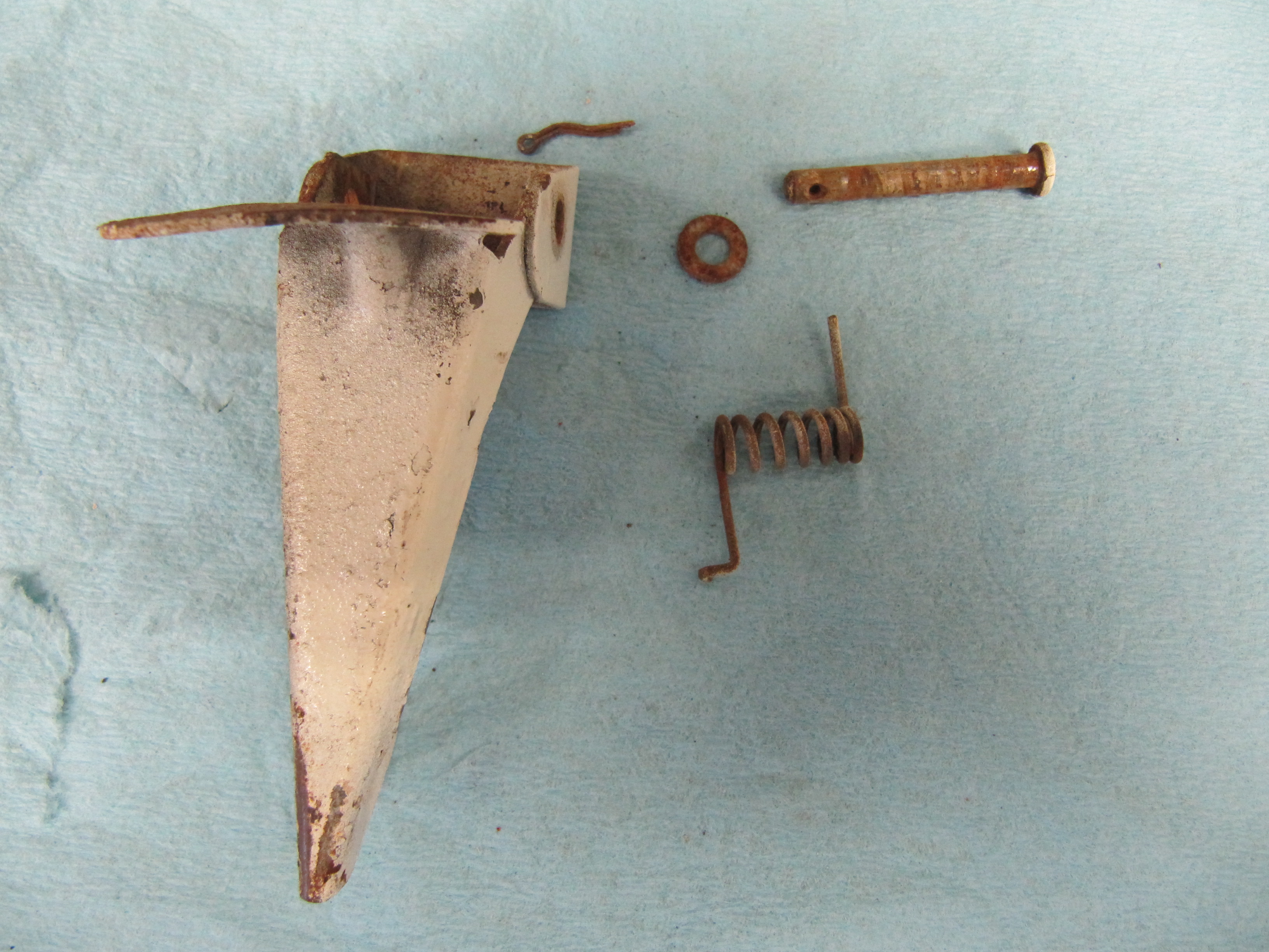
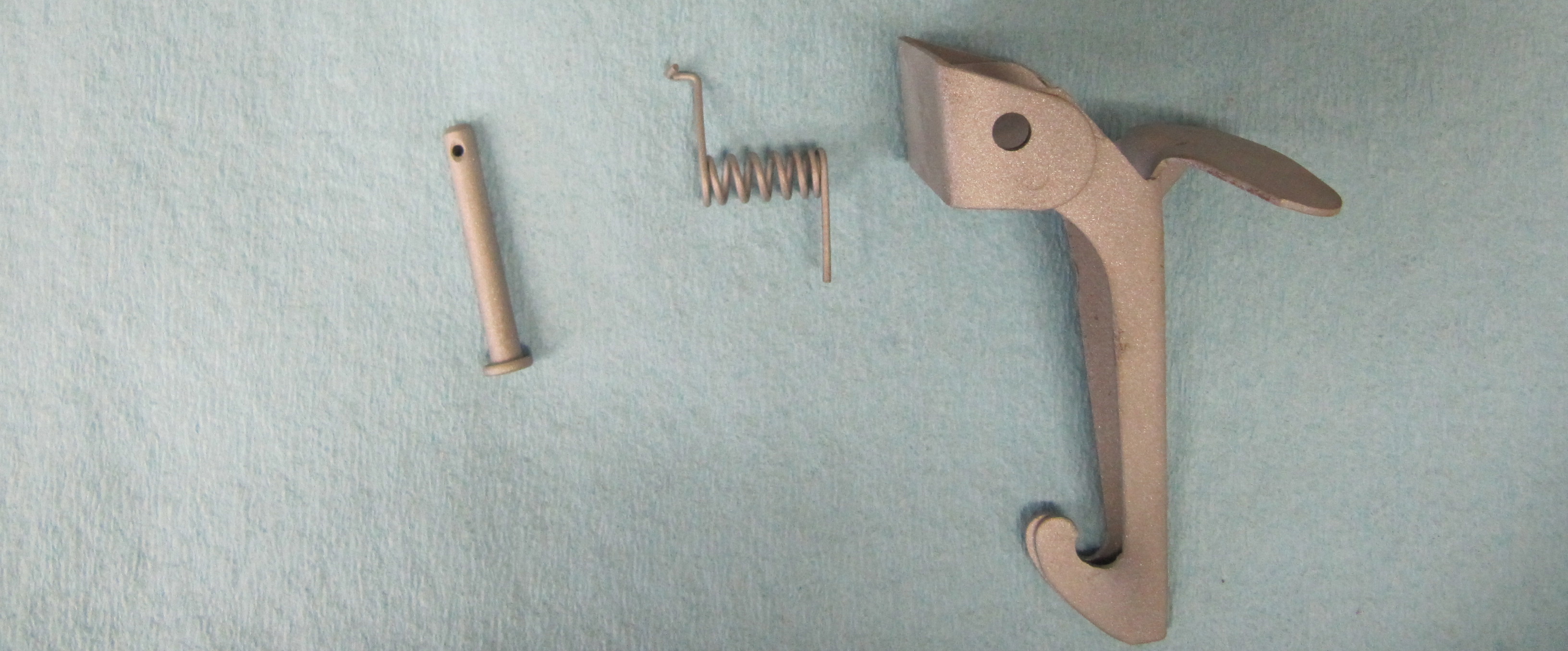
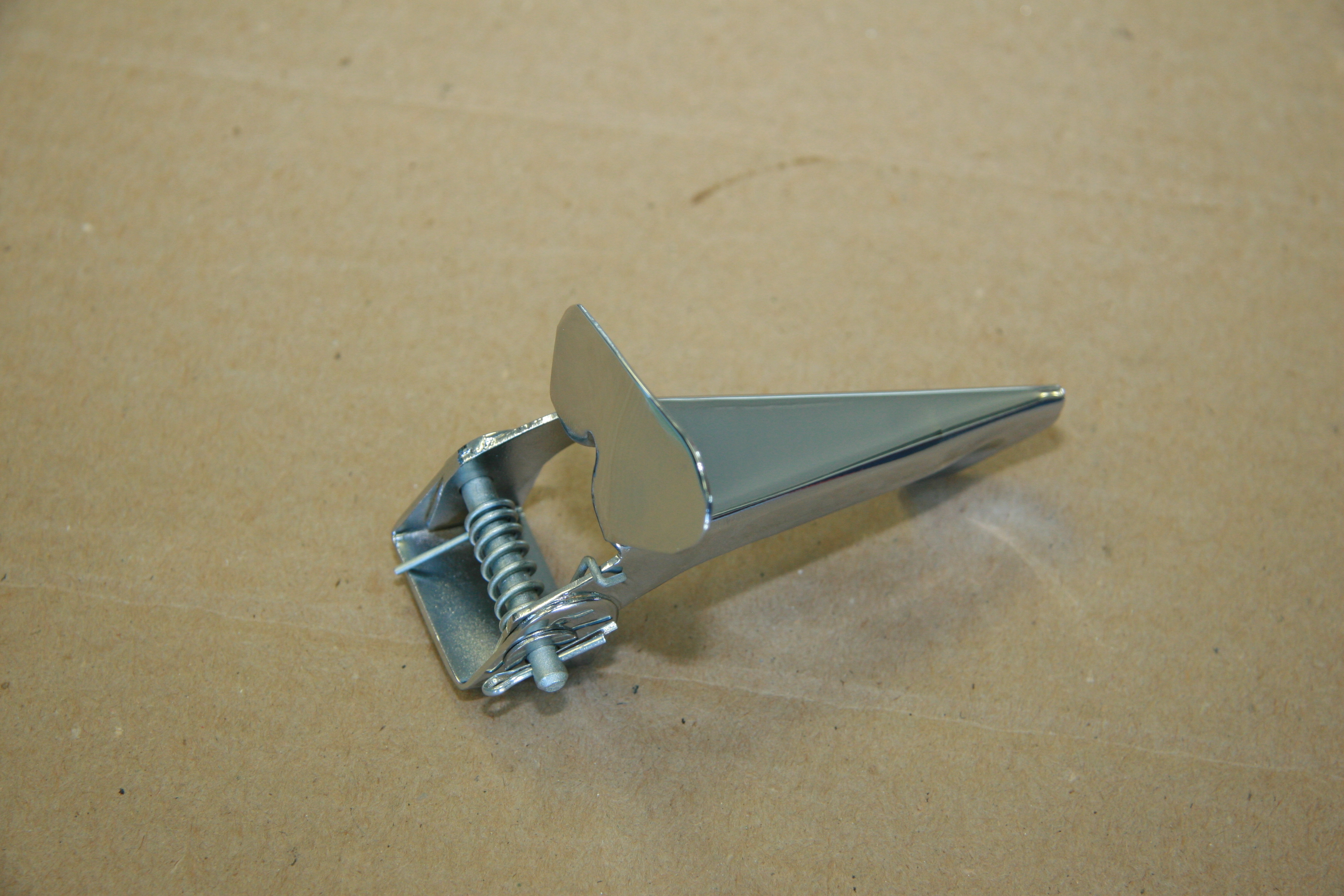
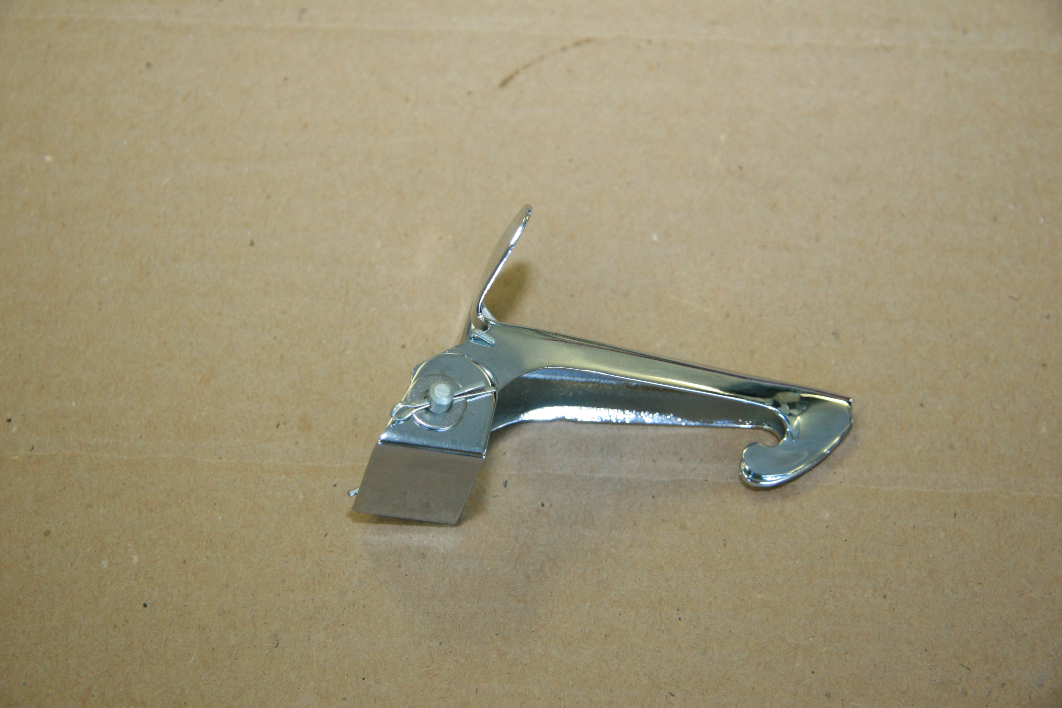
Safety Hook for Bonnet Catch
The safety hook for bonnet catch is comprised of the hook, tension spring, pivot pin, flat washer and split pin. I media blasted these components and while as original they were painted body color, I had the safety hook chromed and the other components cad plated.
Safety Hook
Safety Hook
Safety Hook
Safety Hook Components Cleaned
Safety Hook for Bonnet Catch
Safety Hook for Bonnet Catch
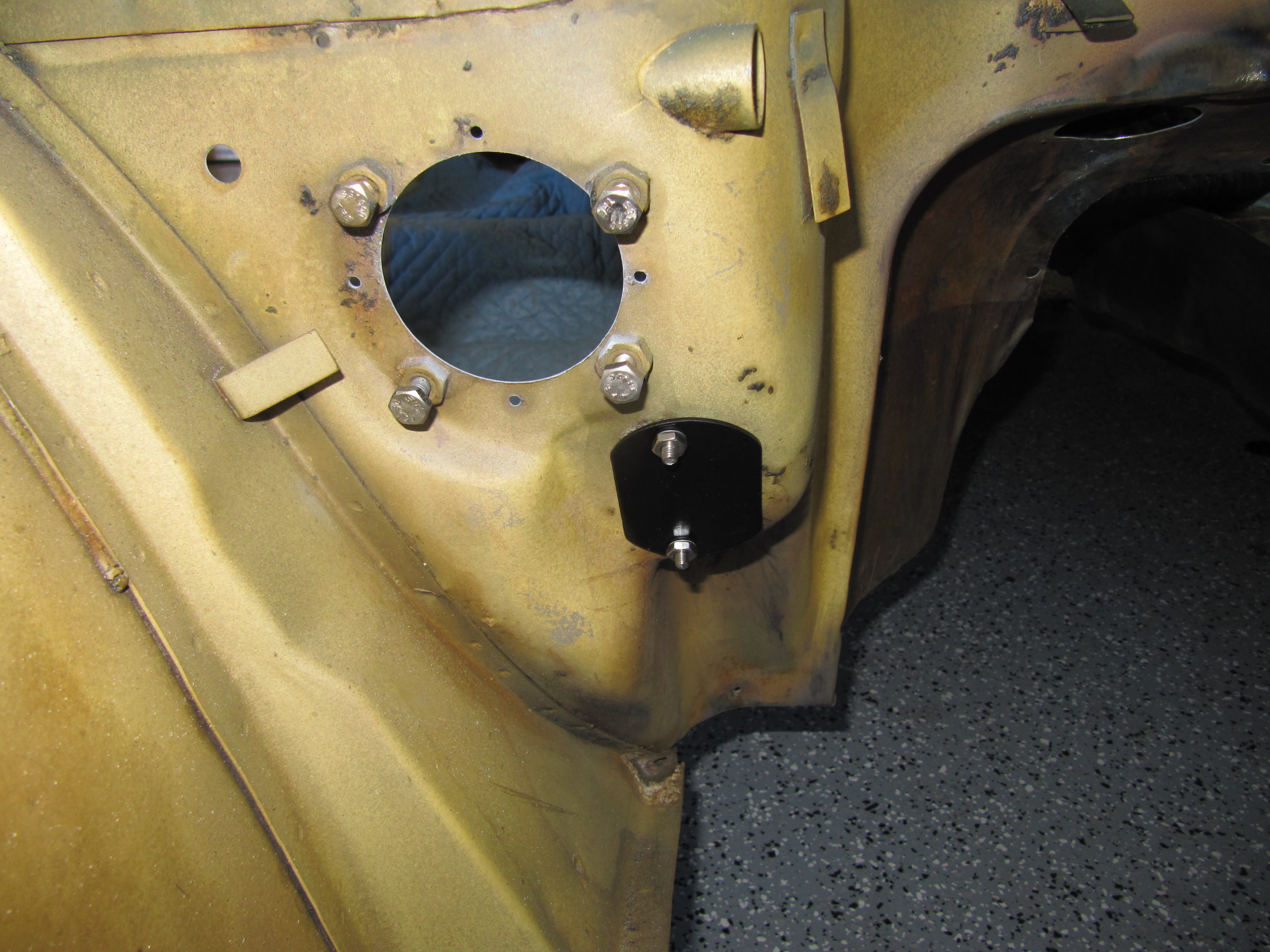
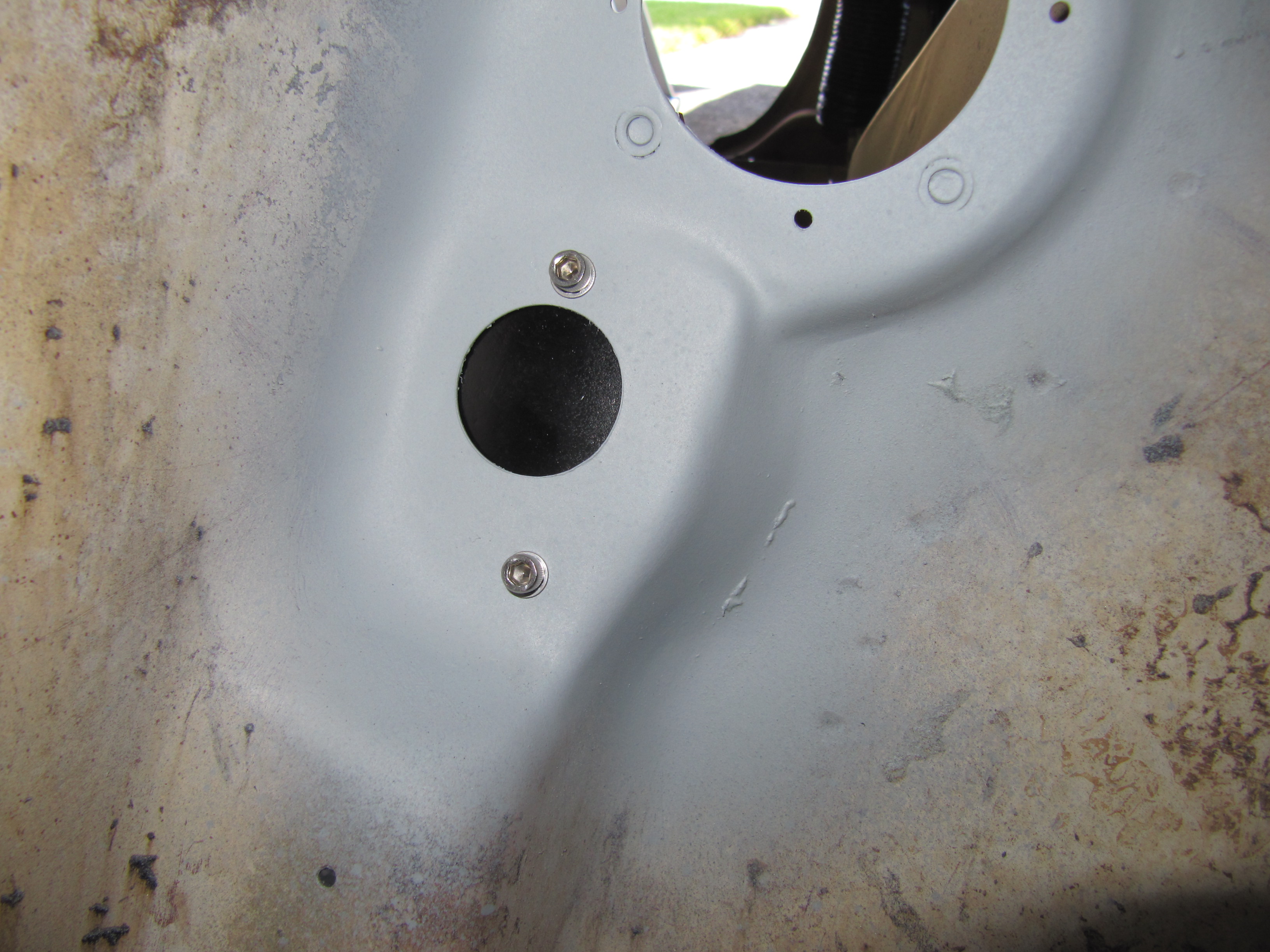
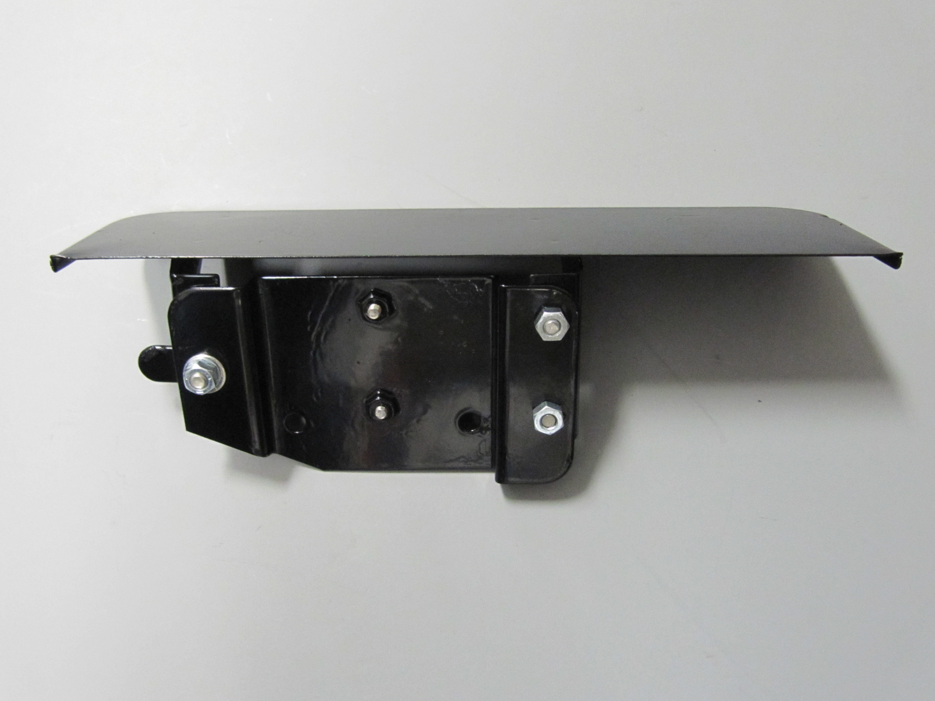
Adaptor Plate Assembly for Solenoid and Solenoid Weather Protection Flange
The starter solenoid and its mounting bracket are fastened to the Adaptor Plate with two #10 – 32 x 1/2″ machine screws and shake proof washers. The Assembly is the mounted to the firewall through the Weather Protection Flange with three 1/4″ – 28 x 1/2″ hex head bolts and shakeproof washers.

Solenoid Mounting
Solenoid Mounting
Solenoid Mounting
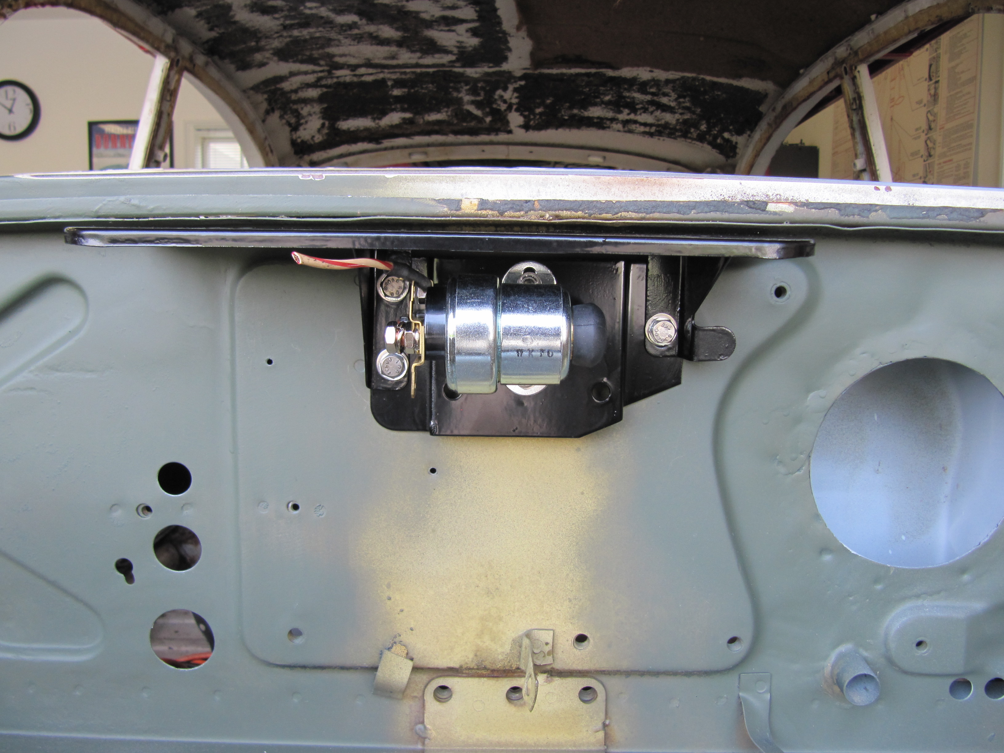
Trial fitting of the Starter Solenoid Bracket and Weather Protection Flange.
Adaptor Plate Assembly for Solenoid and Solenoid Weather Protection Flange

Adaptor Plate Assembly for Solenoid and Solenoid Weather Protection Flange
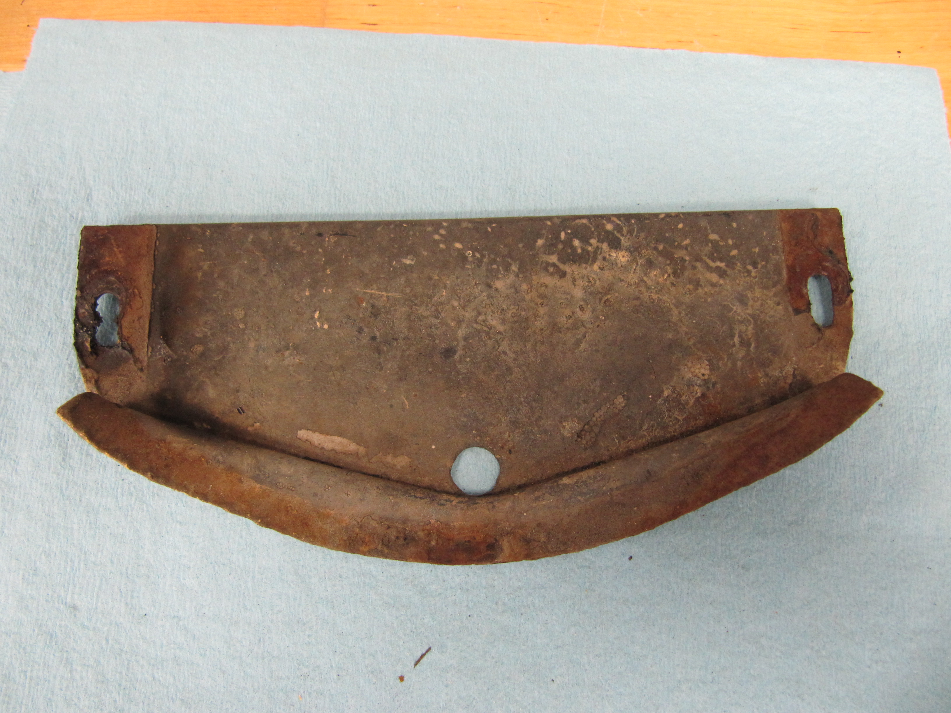
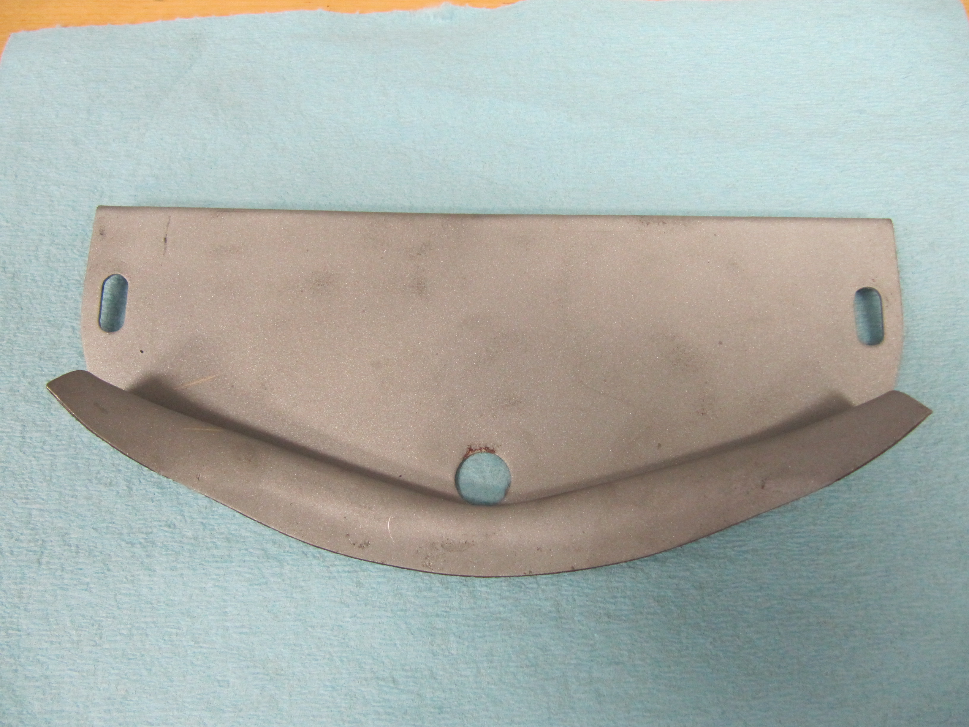
Access Panel for Radiator Grille
A small panel is provided below the chrome grille to access its the fixing points to the body. As with most of the car, this panel was heavily coated with undercoating. I removed the undercoating, blasted the piece and treated it with rust preventative for painting later. The panel is secured to the body with two #10 -32 x 1/2″ slotted machine screws.
Access Panel

Access Panel
Access Panel for Radiator Grille
LH Valance
Getting rid of heat build up under the bonnet is a real problem with the MK2 Jags. I am adding air conditioning that will probably further contribute to the heat issue. Following the lead of some others I decided to remove a lower section of the LH engine bay valance hoping that the opening would help some of the heat escape a little more efficiently. I ordered some stainless wire cloth from McMaster-Carr http://www.mcmaster.com/#standard-wire-mesh/=xas1n5 that has four openings per inch. The cloth is welded not crimped to form the mesh. The idea is that the stainless wire cloth will allow the heat escape but will also keep any road debris from entering the engine bay.
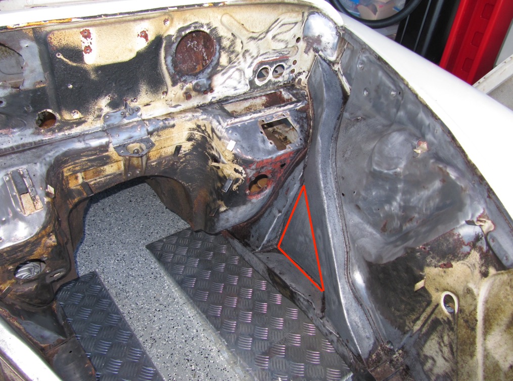
LH Valance Area to be Removed
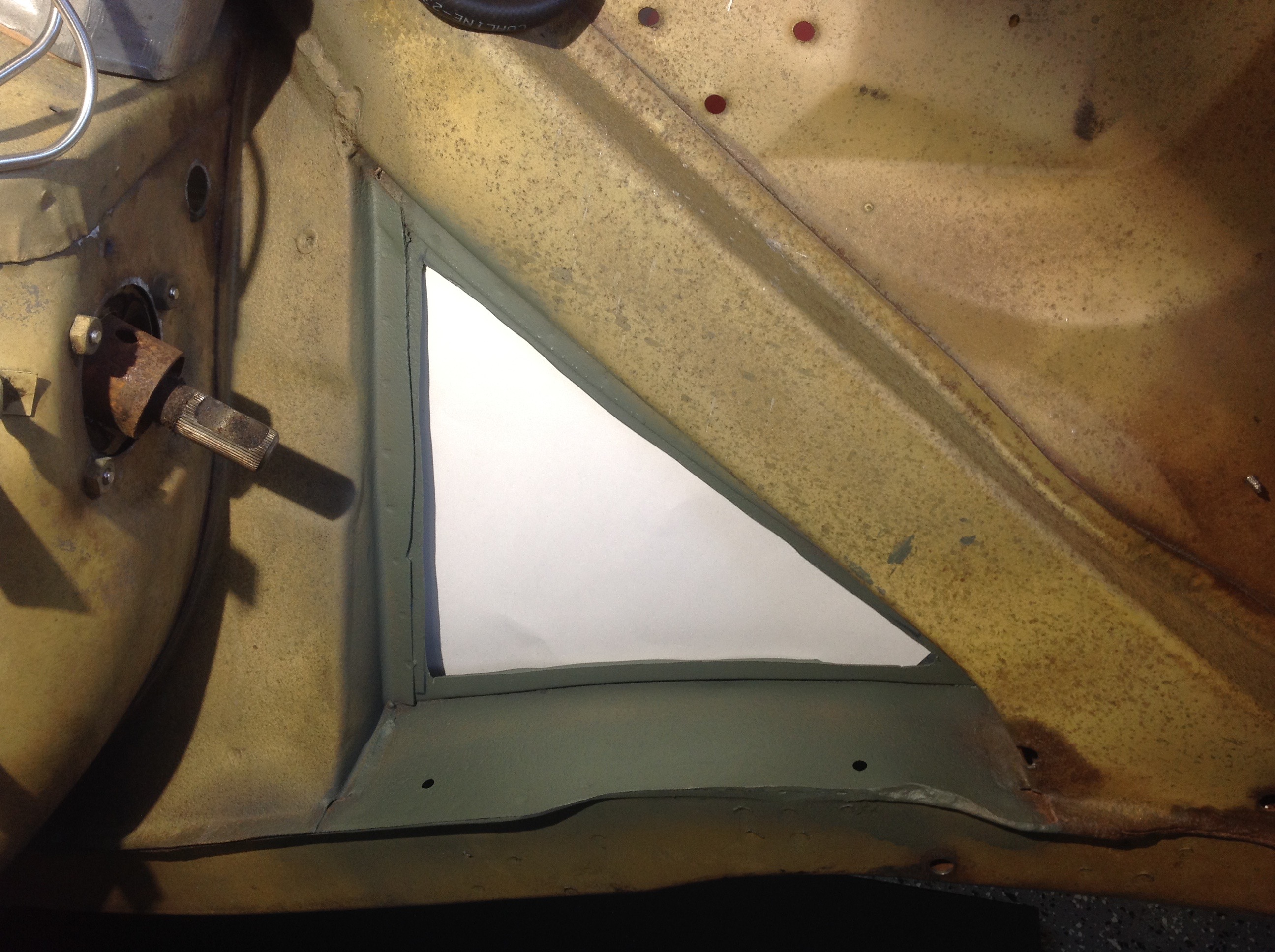
LH Valance Opening for Cooling
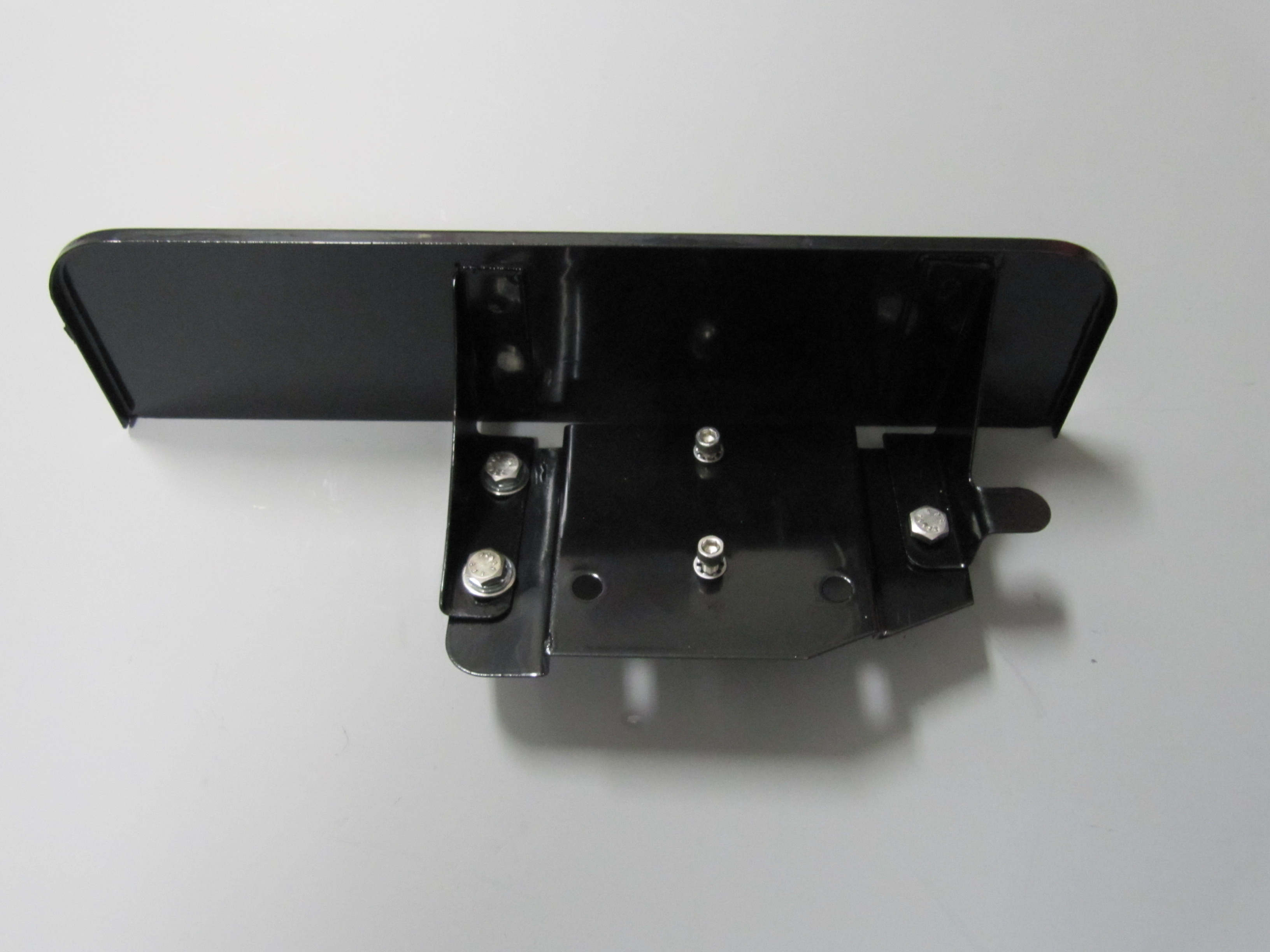
It was a little challenge to get the screen to fit because of the curvature of the sides of the valance opening. I used 1/8″ x 1/2″ steel to frame the mesh cloth and welded the corners. Nut sets were used to fasten the frame to the body so that the screen could be removed for cleaning from the wheel well.
I intentionally left a small gap along the lower edge so that water and grime would not be trapped between the screen and the body. I will have the screen painted body color before final installation.
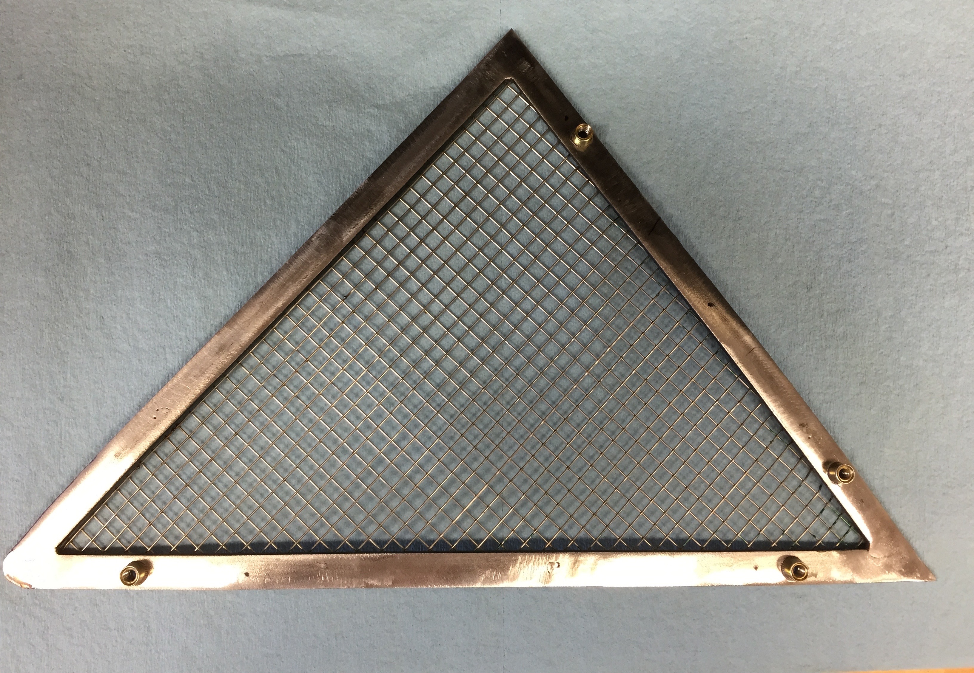
Fabricated Ventialtion Screen
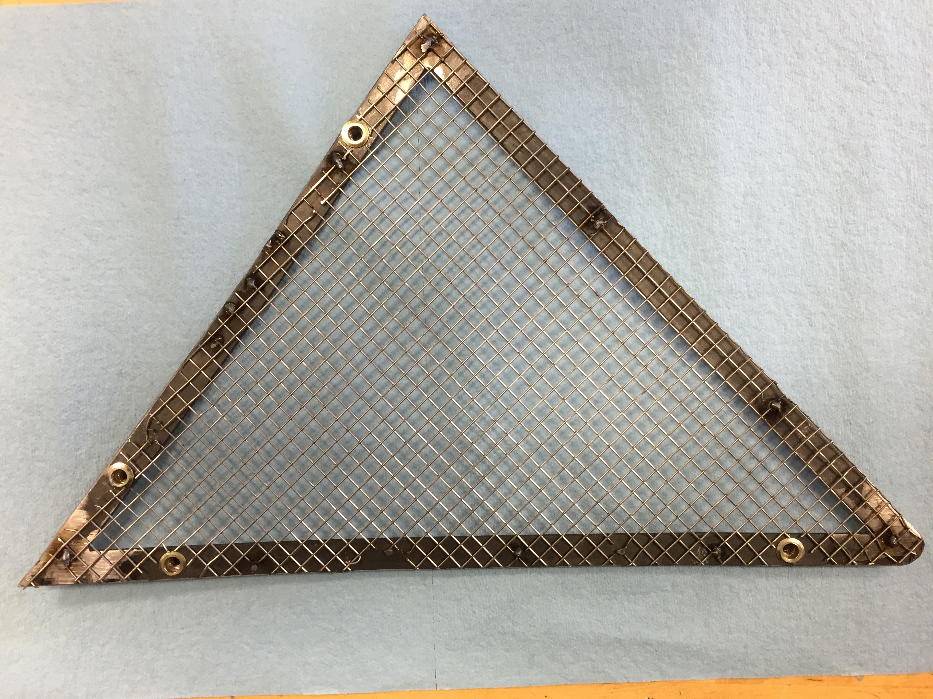
Fabricated Ventialtion Screen

LH Valance Ventilation Screen in Place Inside

LH Valance Ventilation Screen in Place Outside