
Pay no attention to the posting date listed. That date is only used so that the Bugeye posts can be kept in sequence for the reader. The following work was accomplished in the period between July and September 2021. I took the engine and gearbox first, and then later the entire car to my Dad’s home for this work. He has a lift and an air conditioned garage and I am no dummy!
This effort was all motivated by the fact that after about nineteen years the slave cylinder, provided by Bill Perry at Rivergate Restorations for the Datsun 5 speed gearbox, decided to leak and I lost the clutch. Pretty amazing that it lasted that long. Because we used hex head bolts rather than socket cap bolts for the initial installation, I had to remove the engine and gearbox to get to the slave cylinder! Since the engine was out of the car it seemed like the perfect time to do a general cleaning of the engine and refresh other components that also needed attention after almost twenty years.
While the categories are not discreet, rather than discussing the work accomplished chronologically, I will do my best to group the work by function or system within the car.
Body and Trim
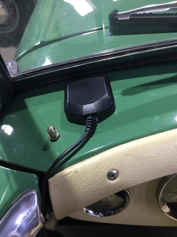
I never liked the front fender mounted rear view mirrors so they were removed and the holes were plugged. A new driver’s side mirror sourced from AH Spares mounted in one of the windscreen post mounting screws was installed. The photo below shows it in the rearmost hole but in that location the side curtains hit the mirror when the door is opened, so the mirror was relocated to the front mounting hole with no issues.
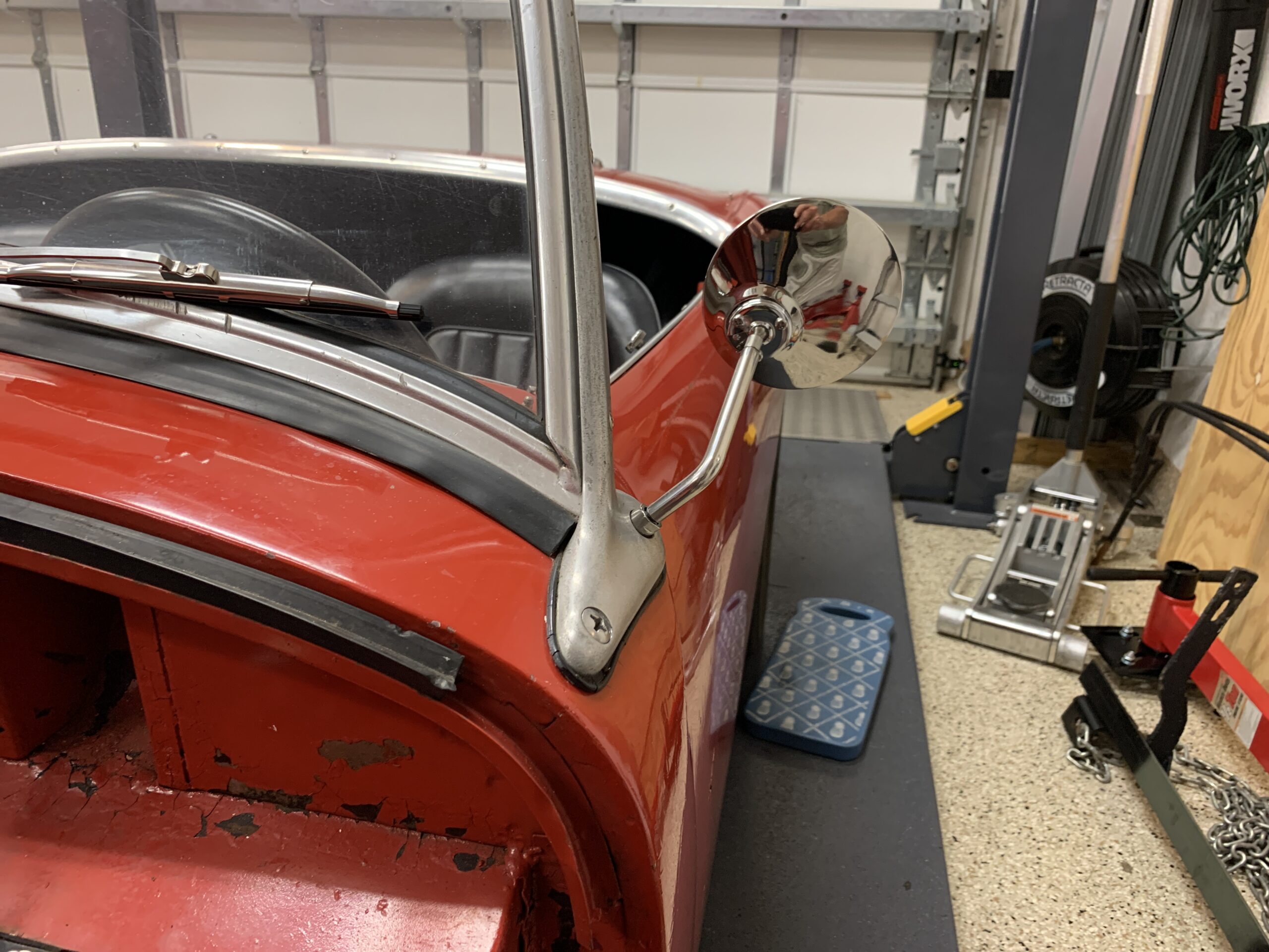
Rear View Mirror Driver’s Side in Windscreen Post
The door latches were misaligned making it very difficult to close the doors without first lifting the interior catch release. Both door latches were nstalled with significant improvement on the driver’s door. The RH door was improved but still not where it needs to be.
The tonneau cover was pretty dirty but otherwise in good shape. A little upholstery shampoo and a good brushing and vacuuming it it looked quite nice.

Tonneau Cleaned
Brakes
Renewing the brakes turned out to be a much less than satisfying experience! The first step in the process was to replace the rear brake cylinders for the drum brakes. The cylinders on the car had been in place for over fifteen years so it was a good idea to replace these before the seals failed.
The rubber plug at the adjuster was removed. Clearly, the plug had been smashed and it was learned after the fact that these plugs work great with standard wheels, but not with aftermarket wheels such as the Panasports that the Bugeye has. The plug can be pushed through the drum and get caught up in the braking mechanism. Upon reassembly the adjuster hole will simply be covered with a piece of tape to keep dust/dirt out.
The adjuster was backed off completely so there would be no shoe pressure against the drum. The two Phillips head screws that go through the drum into the hub were removed.
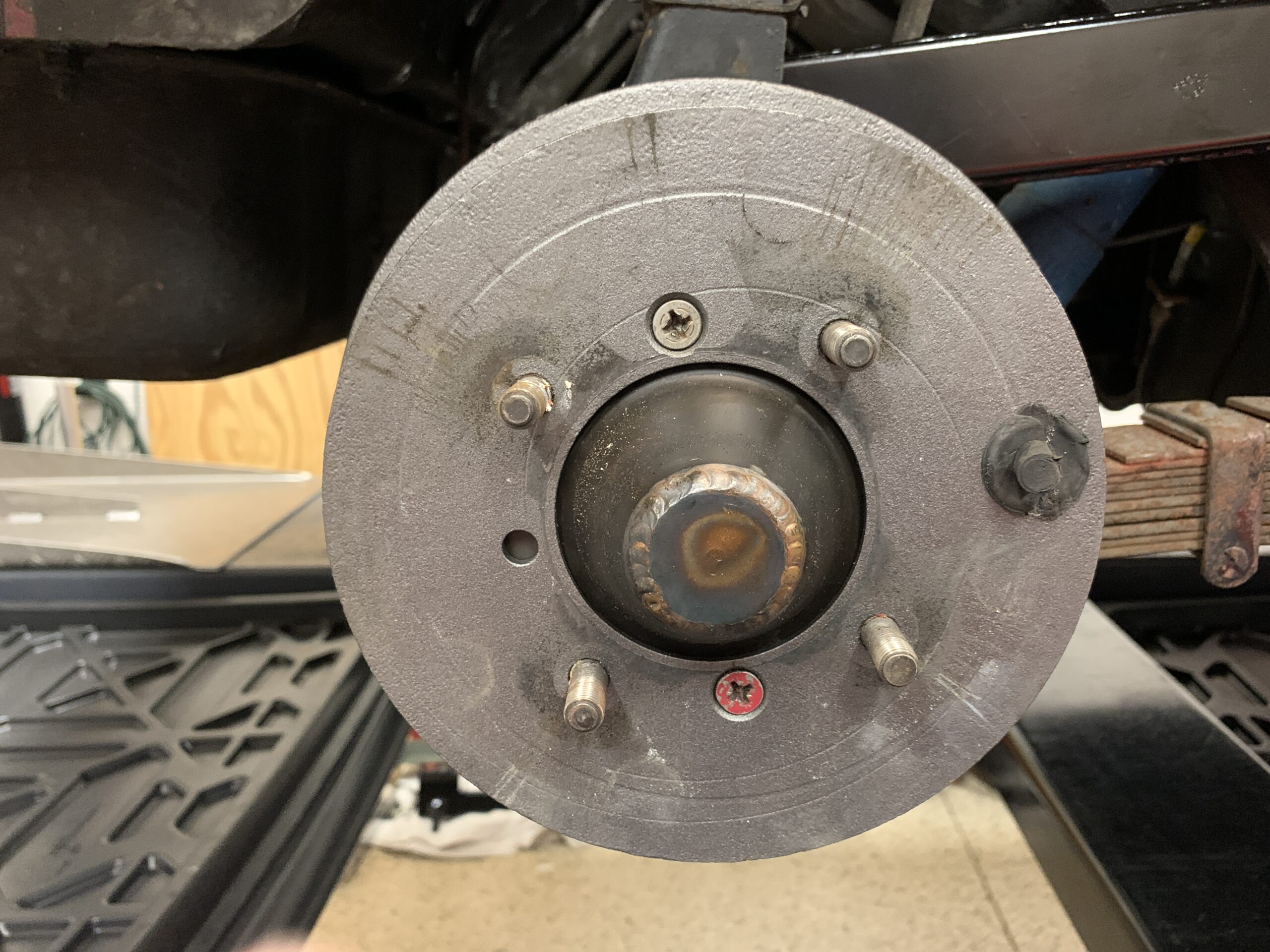
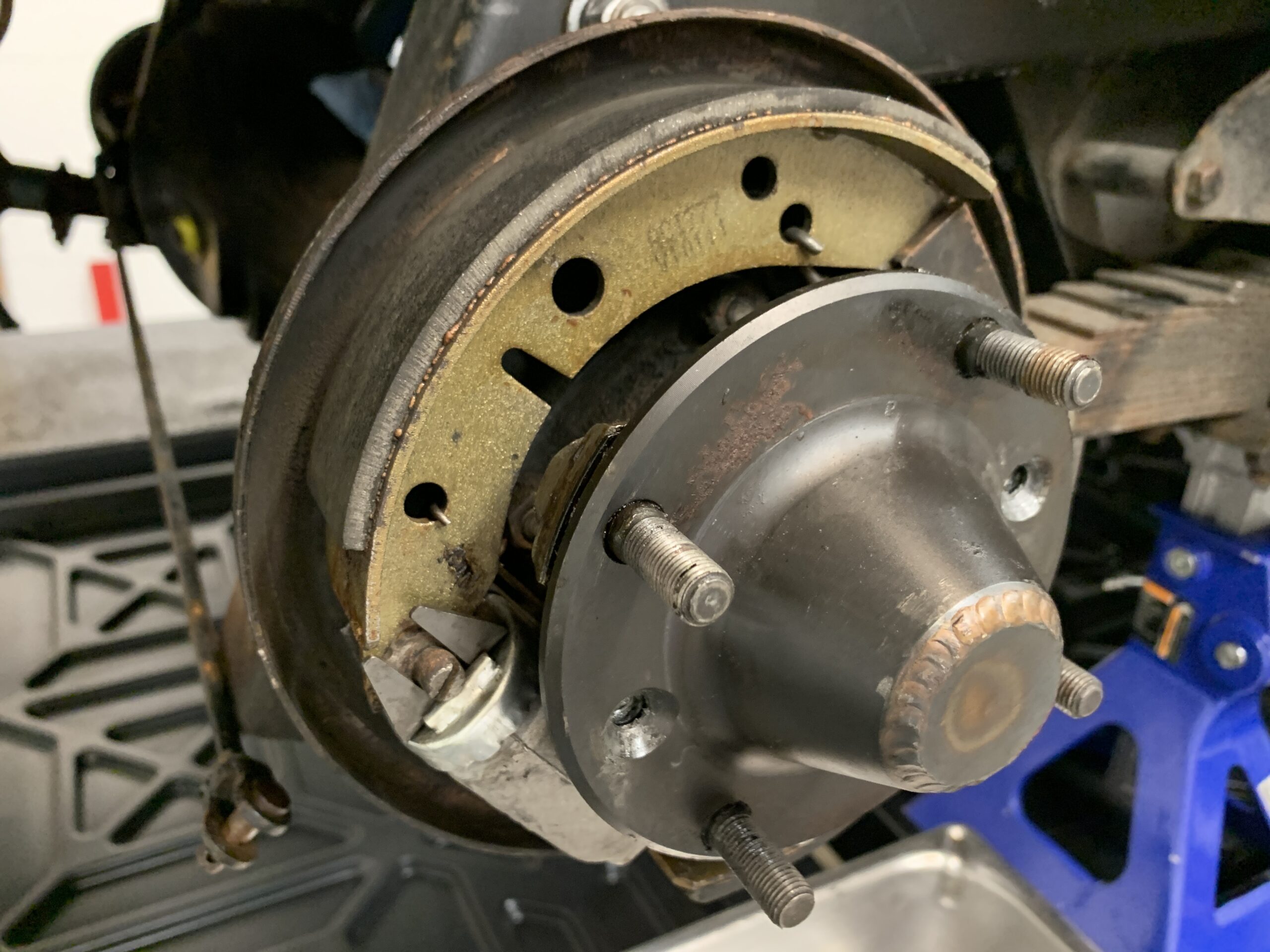
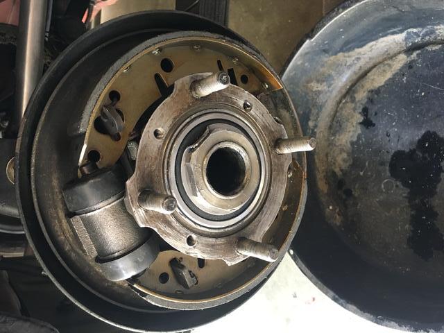
RH Rear Brake Drum
The spring closest to the brake cylinder was detached from the brake shoe. Using a prybar the brake shoe was pushed up and the adjuster could then be removed from the brake cylinder.
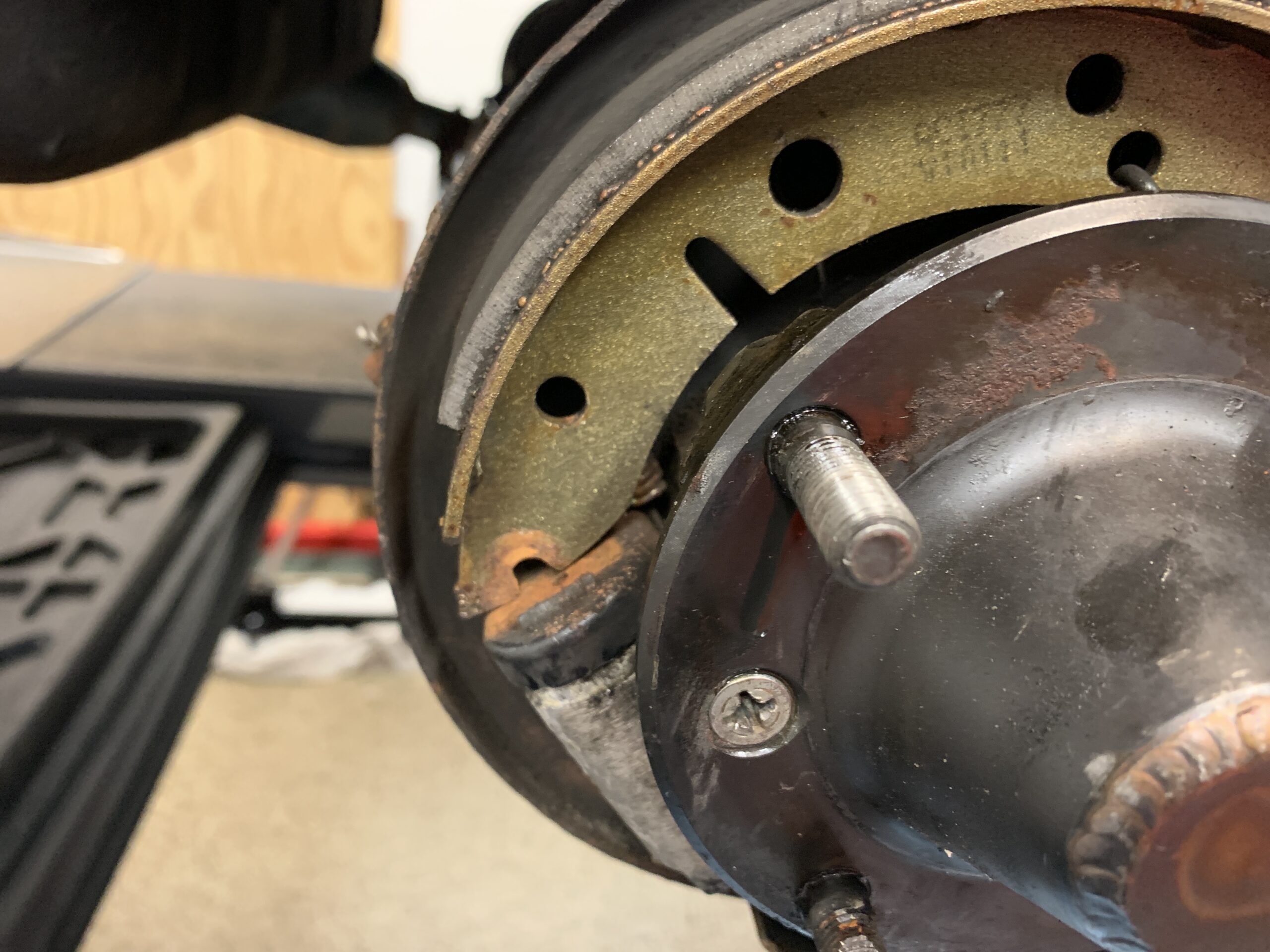
Half Shaft and Brake Cylinder
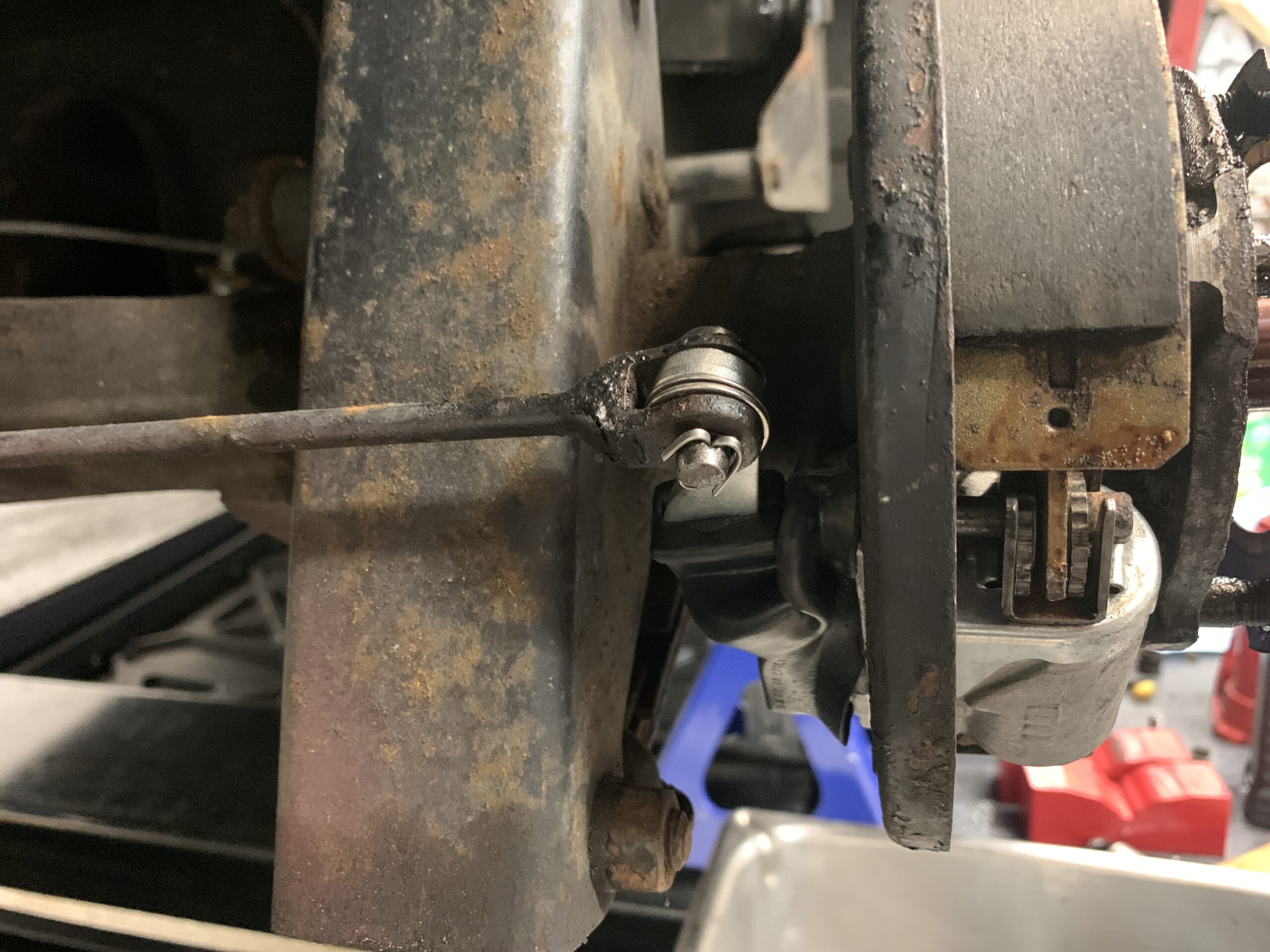
The cotter pin was removed and the handbrake rod disconnected from the brake cylinder and brake lever. The brake shoes and springs were then removed and set aside for reuse.

Handbrake Lever and Rod
It is a struggle to remove the brake cylinder without removing the hub, but it can be done with the proper sequence of moves. After a while I was able to get it out. Of course, I had brake fluid everywhere. Next time I believe it would be best to clamp the flexible line going to the brass union on the axle to avoid draining out all of the fluid from the reservoir! Live and learn.
After cleaning up the surface that the brake cylinder rides on I applied a little grease – not much because you don’t want it on the brake shoes or drum – to the area that the cylinder slides on.
Rear brake cylinder removed
The new cylinder was then put in place and the shoes installed with the springs. Spring installation is easier if one attaches the short stiffer spring first.
Side Note: An earlier blog post details that I broke a half shaft not too long after I got my Bugeye. The shafts were replaced with hardened axles from The Winner’s Circle. It was not recognized until undertaking this brake project, that these shafts only have two countersunk holes for locating the half-shaft to the hub and then for the brake drum to the hub. This worked, but it also meant that every time one removes the drum the half-shaft is also loosen from the hub ensuring a breaking of any seal retaining the gear oil in the axle casing. When disassembling the next time, we will try to drill an additional hole in the half shaft so that it can be secured to the hub independent of the drum. The two holes can be seen in the photo below.
New brake cylinder, shoes and springs installed
This image from another car shows the third hole in the half-shaft that we are missing.
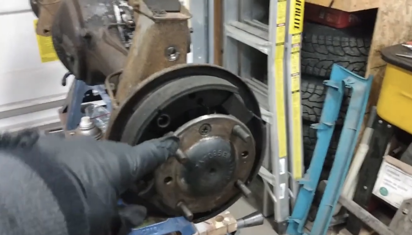
Half Shaft Mounting Hole and Screw
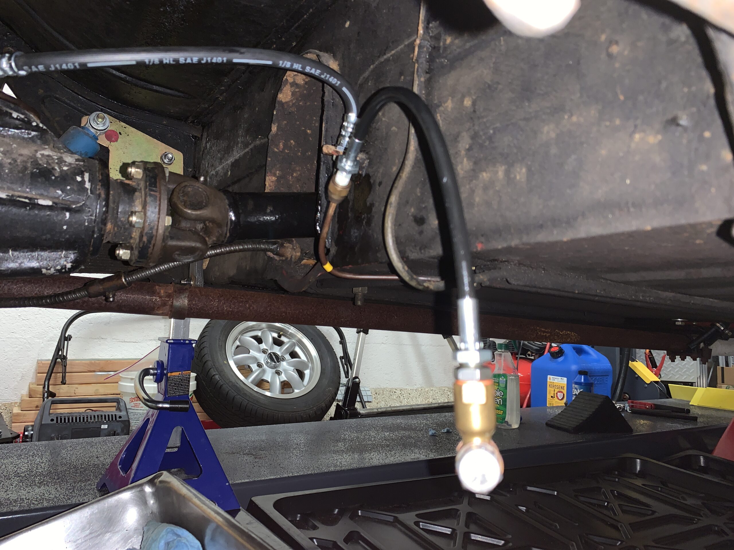
Got a new cunifer brake and clutch line kit from Vintage Pipes. Bent and Installed the right rear pipe from the wheel fitting to the brass junction on the top of the differential.
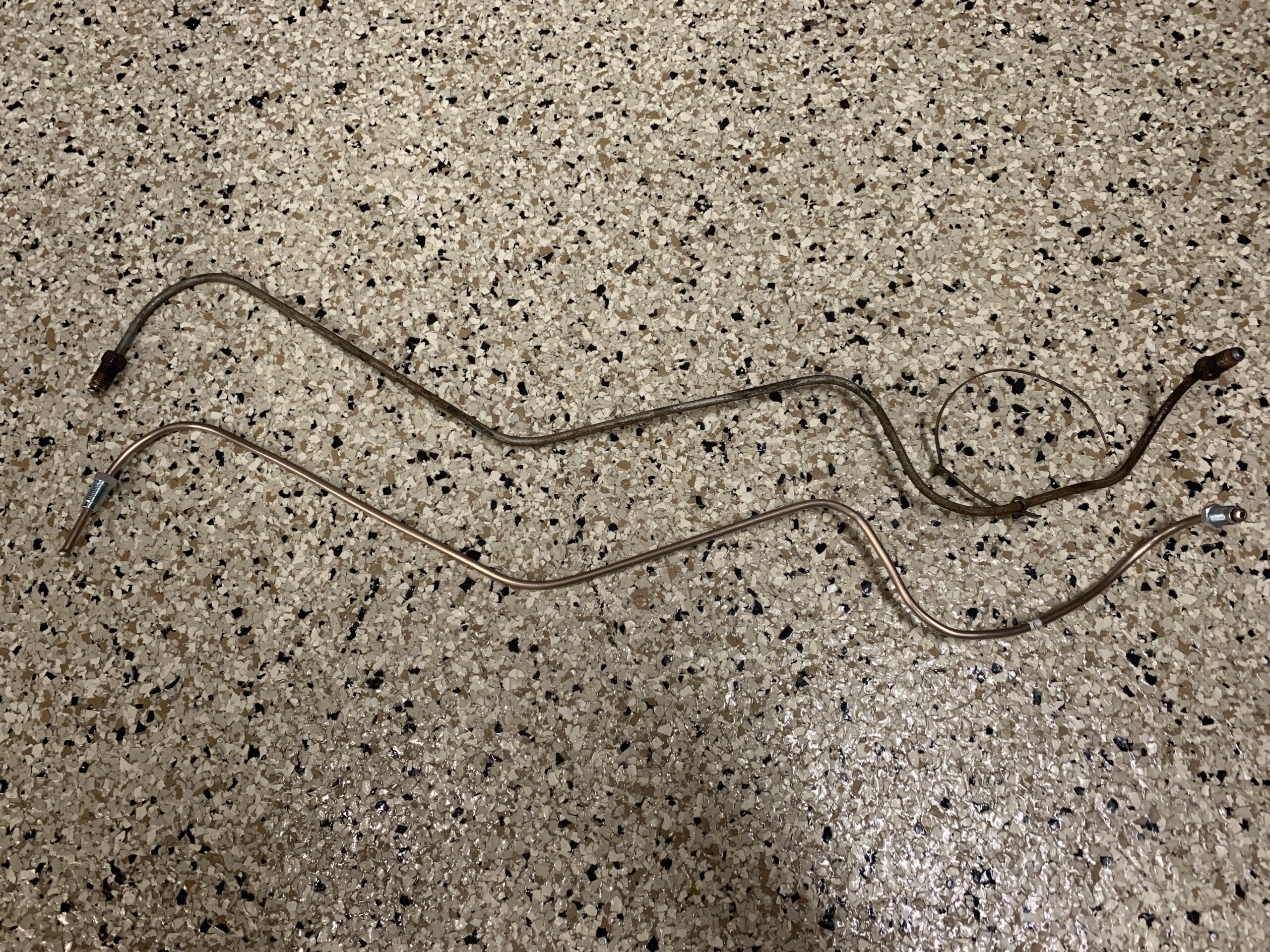
Old and New Brake Pipe
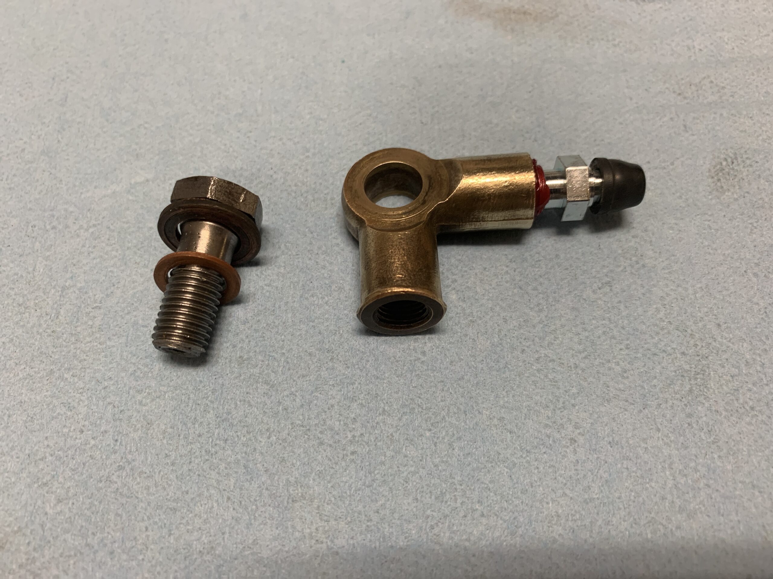
Brake Pipe Brass Fitting, Banjo Bolt, and Bleeder Valve
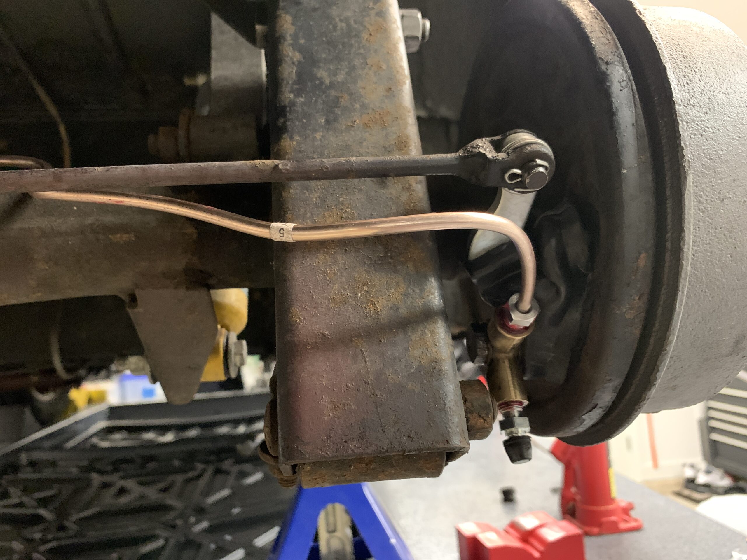
New Cunifer Brake Hard Pipe Installed
All of the preceding steps were then replicated on the LH side of the car. It was then time to bleed the system. Following repeated unsuccessful attempts to get the air out of the lines, it was discovered that the brass fitting at the brake cylinder was installed incorrectly! This image from the workshop manual illustrates the correct positioning. I took the assemblies apart and repositioned the bleeder to the place it where it should be.

Brake Bleeder Position
This photo shows how the bleeder should line up relative to the lever boot. After tightening down the hard brake pipe the bleeder will shift to a position similar to the manual diagram.
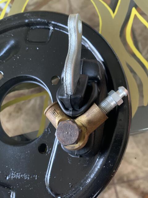
Brake Bleeder Positioning
Folks on the Sprite Forum suggested strongly that speed bleeders really help with bleeding the brakes on the sprite so before I try bleeding again replaced the new bleeders that I recently installed with a set of speed bleeders.
Sprite Speed Bleeders
Each brake shoe is “steadied” with a “beehive” retaining spring. In trying to install the beehive spring clips on one of the brake shoes I found it to be almost impossible. After watching a few videos I discovered that it looked like the original beehive clips had a bigger gap in them than the ones received from Spridget Mania. So the “U”portion of the new springs was shortened a bit with a Dremel cut off wheel to try to make the job a little easier this photo shows the difference after doctoring the “U” portion slightly.
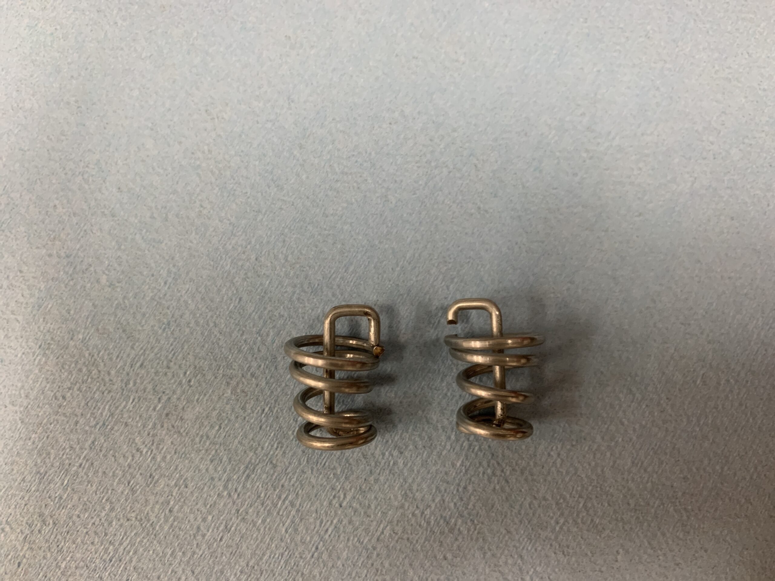
Modified Beehive Springs
Beehive steady springs Installed
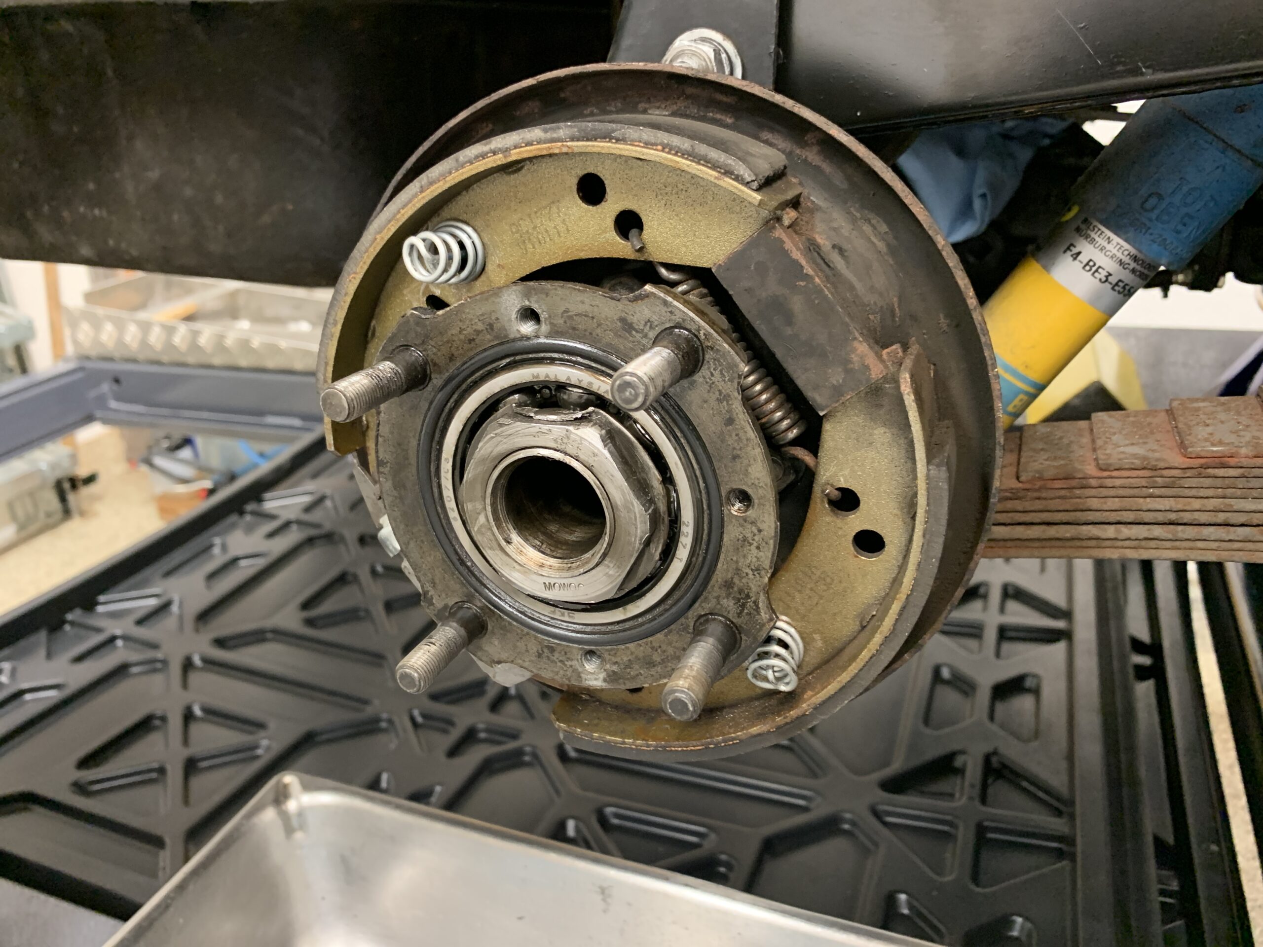
The brake shoes were then centered on the backplate and then pushed over the shoes. The two hex screws were then installed through the axle into the hub. To make sure that it was good and tight, four nuts were installed on the wheel studs with an impact gun, and the drum screws were tightened again. The assembly was then left to sit for a day or so to make sure things are snug.
I then reattached the handbrake rod to the brake cylinder and added a few stainless steel washers with a new cotter pin.
Reconnected Handbrake Rod to Lever
After realigning the hard pipe and the bleeder, and installing the speed bleeders another attempt at bleeding the system was undertaken. This time the Gunston EEZIBLEED system was used to bleed all four corners of the car as an alternative to the traditional two person brake bleeding system.
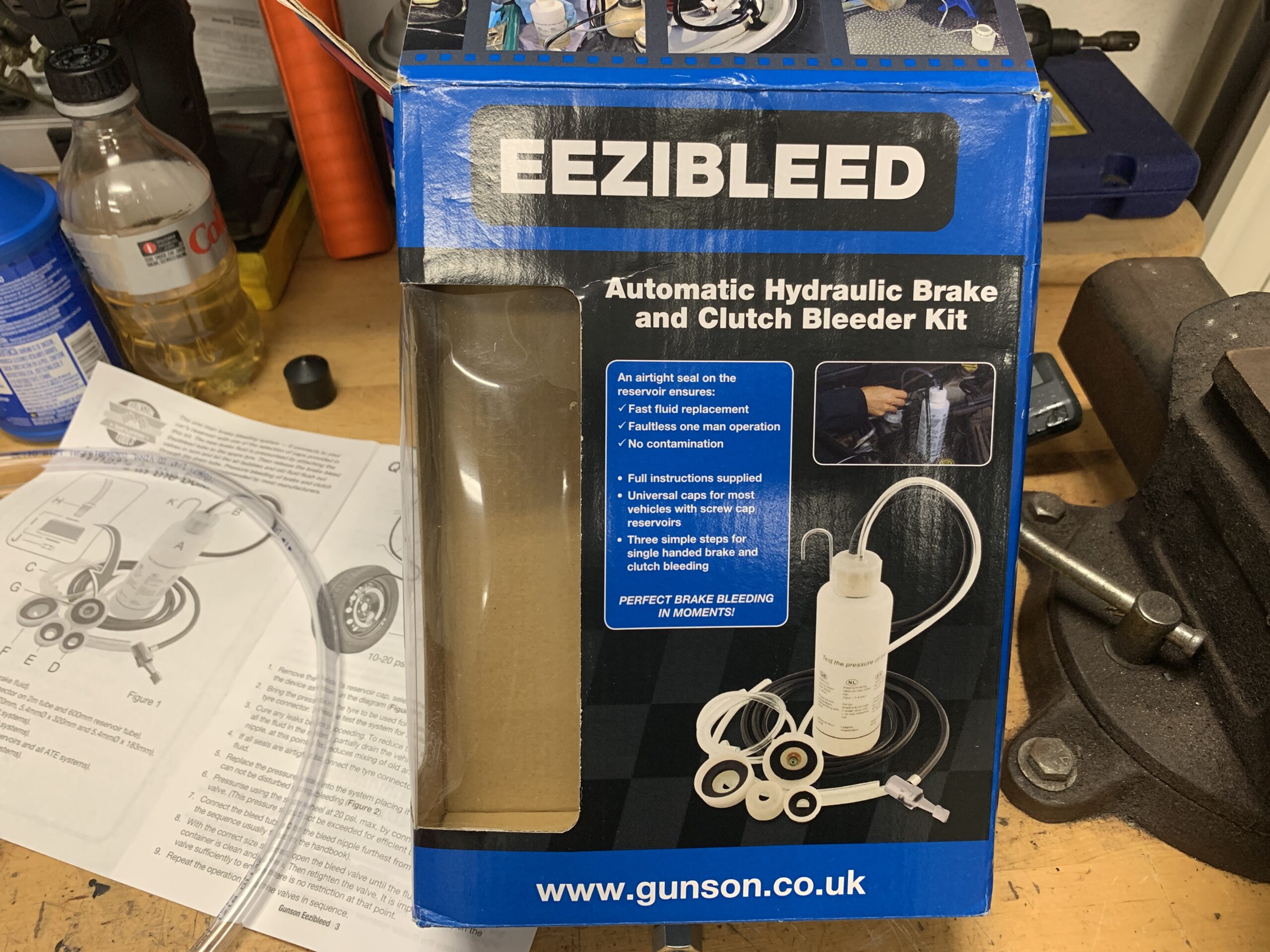
Gunston Automatic Hydraulic Brake Bleeder
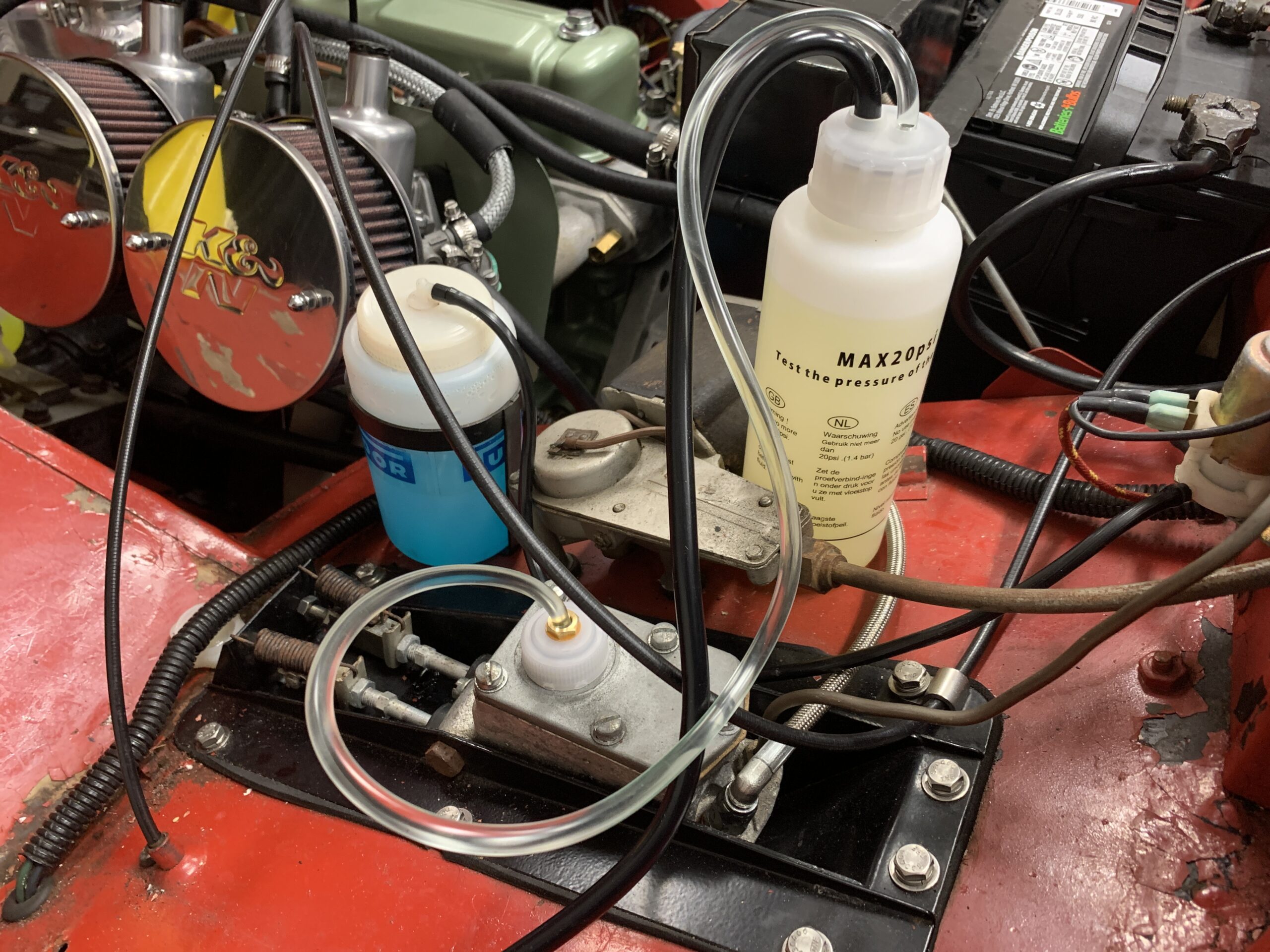
Gunston Bleeder System
Unfortunately, it didn’t produce any more positive result than the traditional system. There must be air in the master cylinder and so it will be necessary to bench bleed the master cylinder which will be attempted with it mounted in the car. To bleed the master cylinder, I suctioned out some brake fluid and then removed the five screws and the top of the master cylinder.
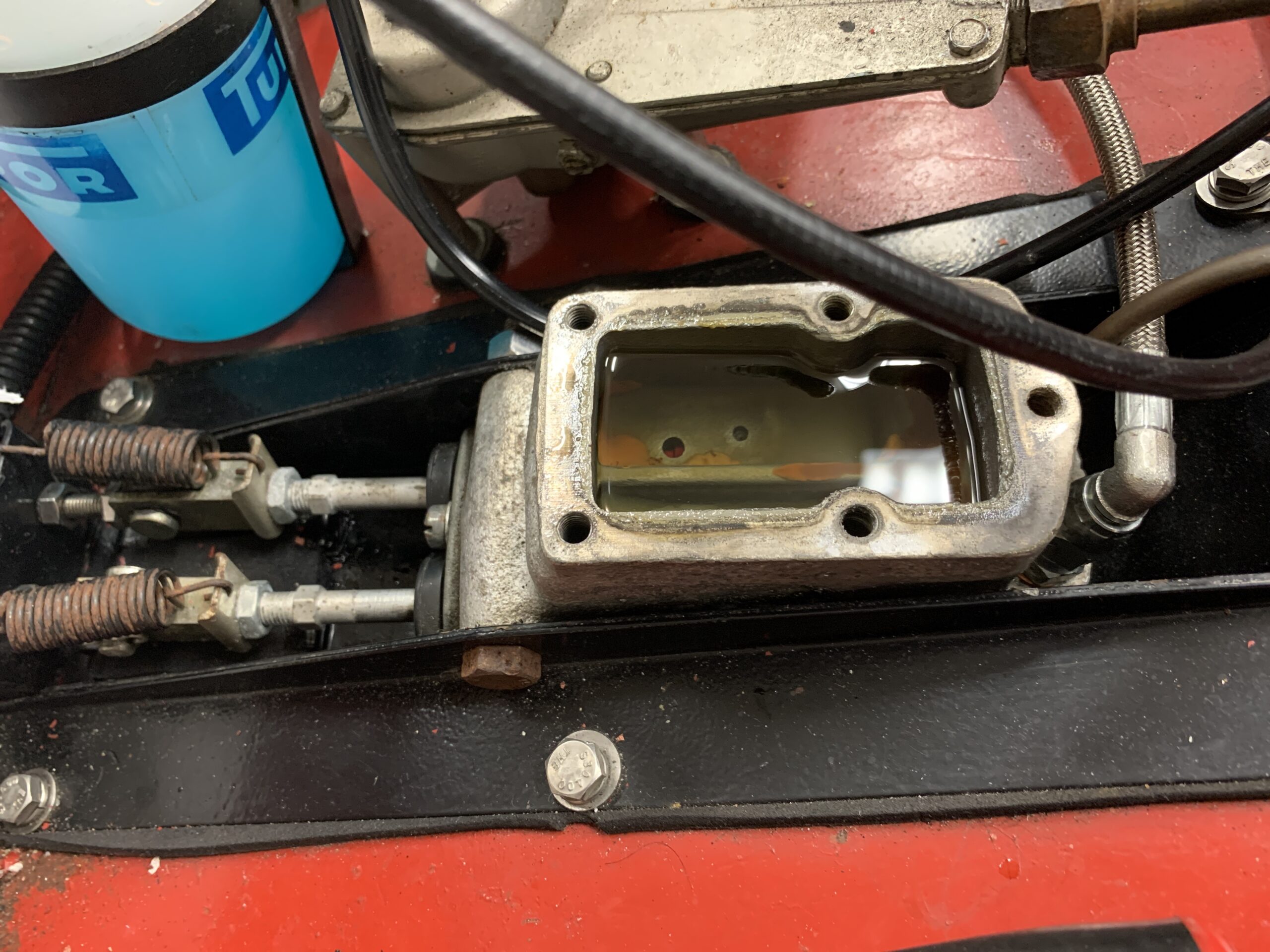
Preparing to Bleed the Master Cylinder
I then disconnected the brake pipe fitting from the master and installed a plastic fitting from a master cylinder bench bleeder kit with a clear tube attached to it to affix in the master cylinder fluid.
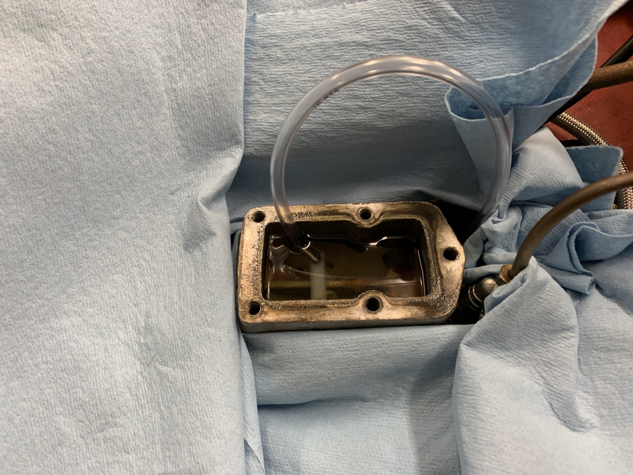
Bleeding the Master Cylinder
The bleeding of the master cylinder was successful. The system was bled once again with no success. Air is trapped someplace and a good pedal cannot be achieved.
It was decided to block off the rear brakes to test the front brakes alone. If a good pedal can be realized with just the front brakes then it can be concluded that the master cylinder is fine, and the problem is in the rear, probably with the new brake cylinders.
Rear Brakes Hydraulics Blocked
With the rear brakes blocked from the system, a good braking action was obtained with the front brakes. Apparently (?) the rear brake cylinders are the culprit. We had long thought about converting to later midget rear brakes that have a dual action brake cylinder as shown in the photo below. This is a common upgrade when the front drum brakes get converted to the later disc brakes. Rather than wrestling with these anymore it was decided that we would pursue trying to find the backplates from a later midget and make the swap.
Later Midget Rear Brake Assembly
This means that the car will go home with only front brakes, and while we are not happy about failing to complete this task we will end up with a better system later.
Clutch
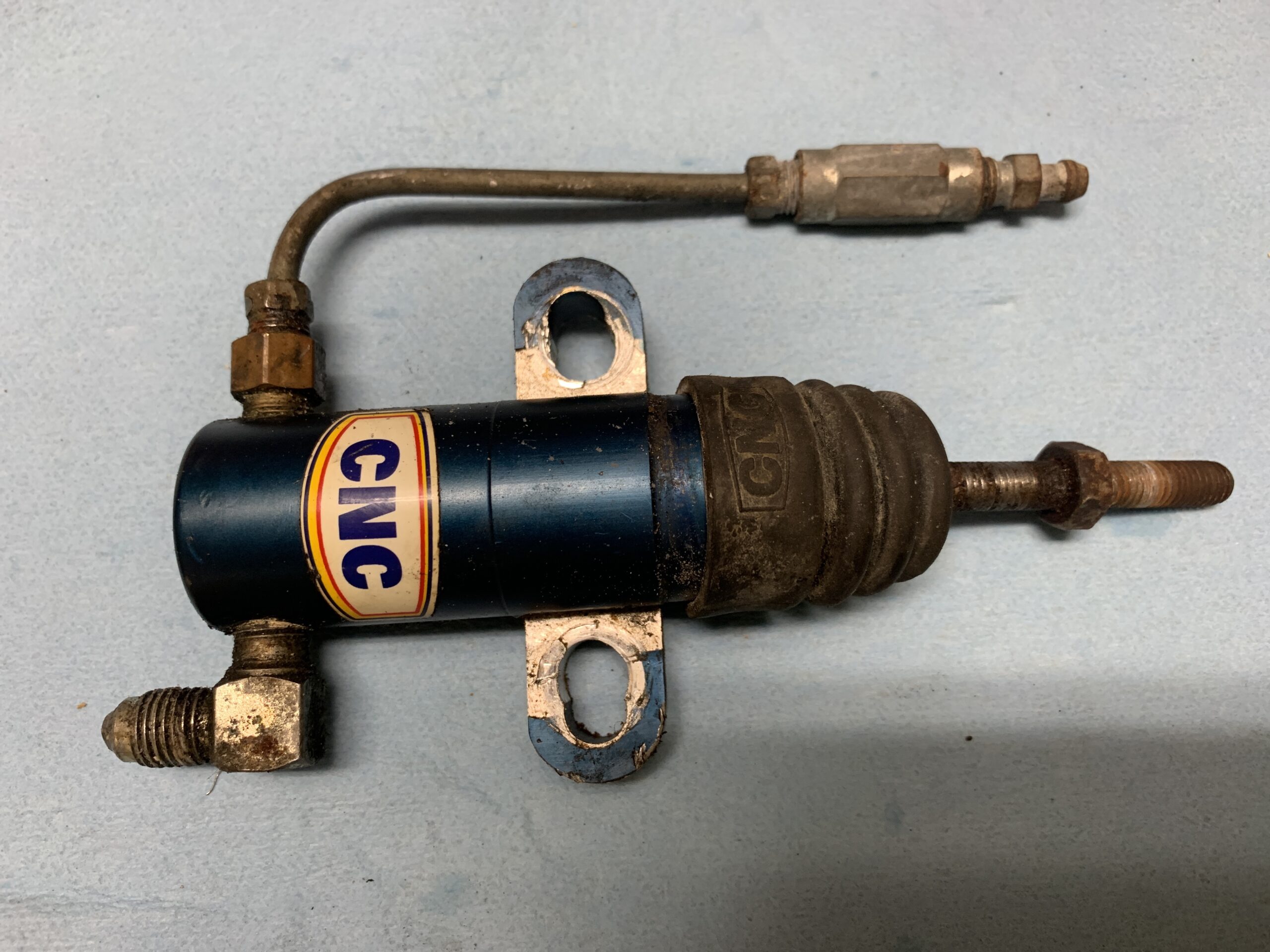
The motivator for this entire job was the need to replace the slave cylinder. The slave cylinder on the Datsun B210 gearbox is on the LH driver’s side, while on the Healey gearbox it was on the RH side. Doug Reid (now deceased) made the remote bleeder valve at my Dad’s request to make it easier to get to the bleeder.

Rivergate Slave Cylinder
The slave cylinder pushrod threads protrude 1/2 inch from the arm. Strangely, the upper bolt holding the slave cylinder to the transmission casing is metric and is 17 mm while the lower bolt is 5/8 of an inch. I marked each bolt with a L or a U so as to know which one goes where.
Rivergate Slave Cylinder Pushrod
Removed slave cylinder with the mounting plate by pushing it to the front of the engine. Next step is to remove the push rod.
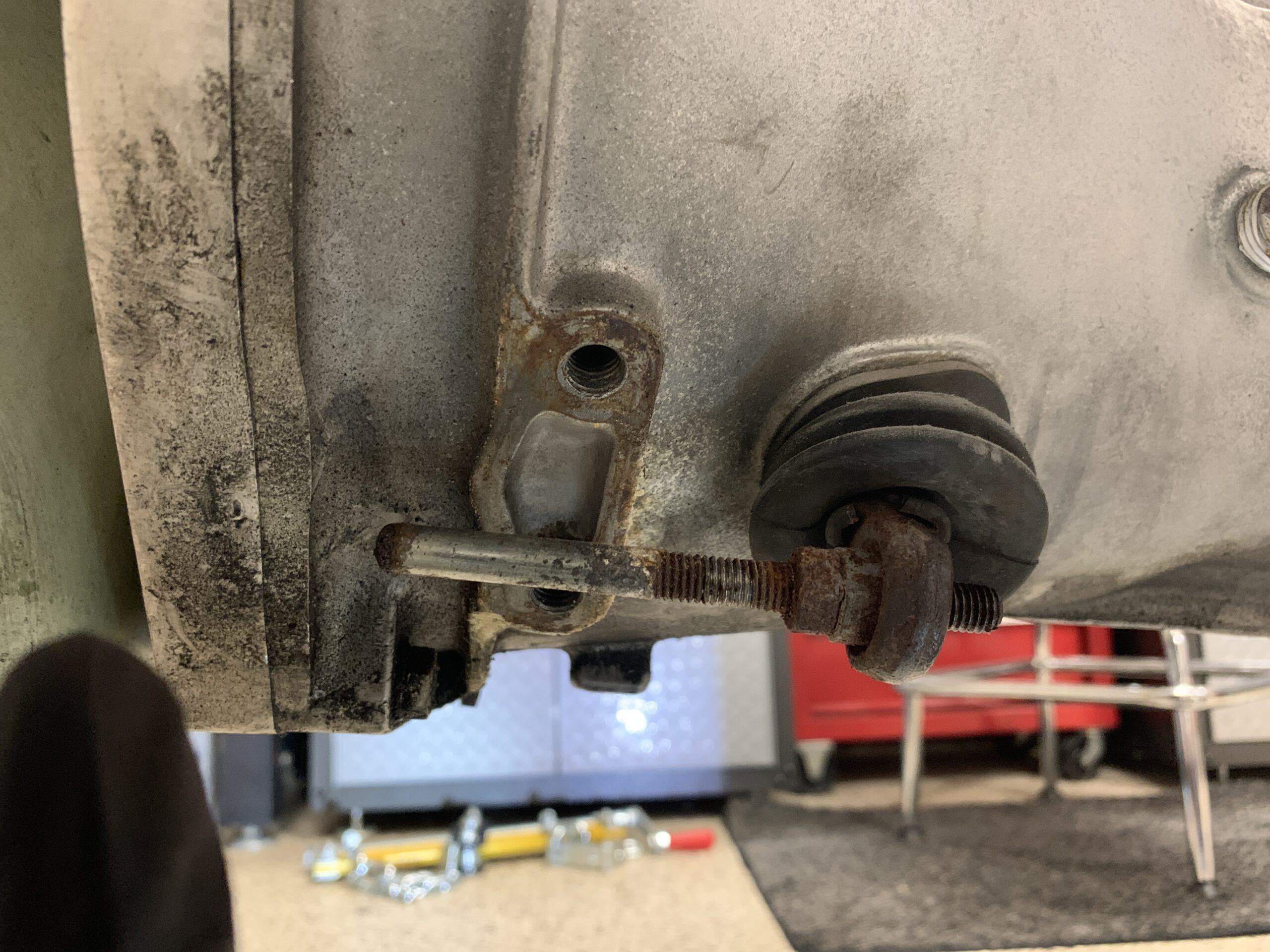
Push Rod Removal
Slave Cylinder, push rod and bleeder extension assembly removed.
Rivergate Slave Cylinder Assembly Removed
A new aluminum 7/8″ slave cylinder was ordered from Rivergate Restorations. Different color and different bleeder valve. The new slave cylinder was installed with cap screws and along with a slightly shortened Allen wrench key, the cylinder can now be installed AND REMOVED without pulling the engine!!!!
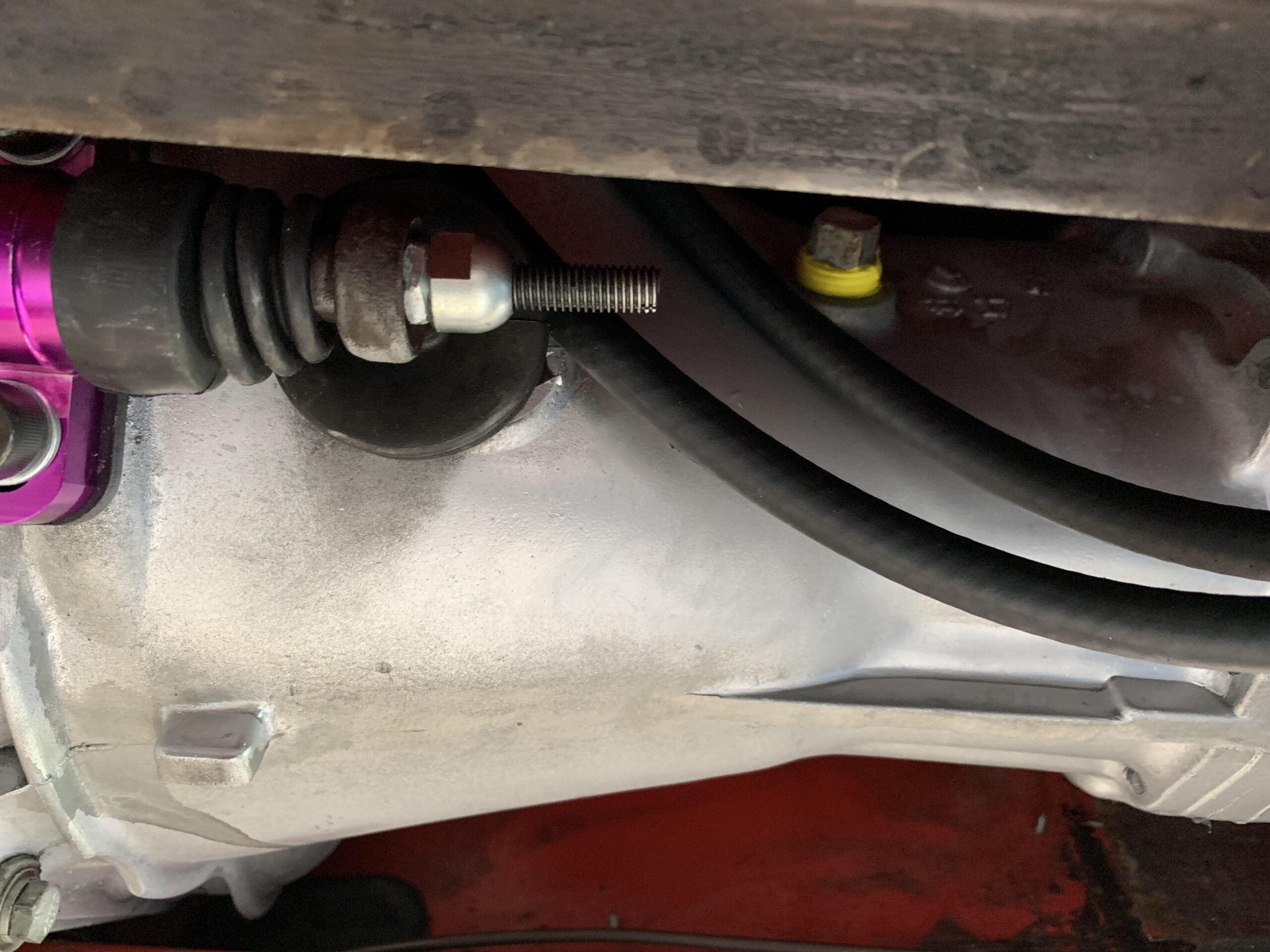
New Slave Cylinder Installed
Final adjustment is with the pushrod extending beyond the fork by 1 9/16”.
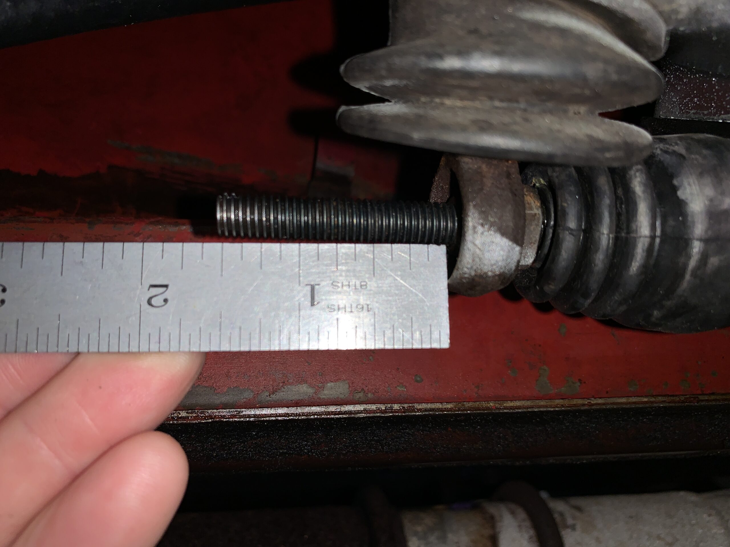
Slave Cylinder Pushrod Adjustment
The clutch works fine now. Mission accomplished.
Cooling
Following removal of the alternator from the engine, I removed the fan belt and will replace it. The installed belt was cogged but it will be replaced with a smooth surface proper “V” belt. This one is a NAPA premium XL 25-7355 or Gates 7360 fan belt.
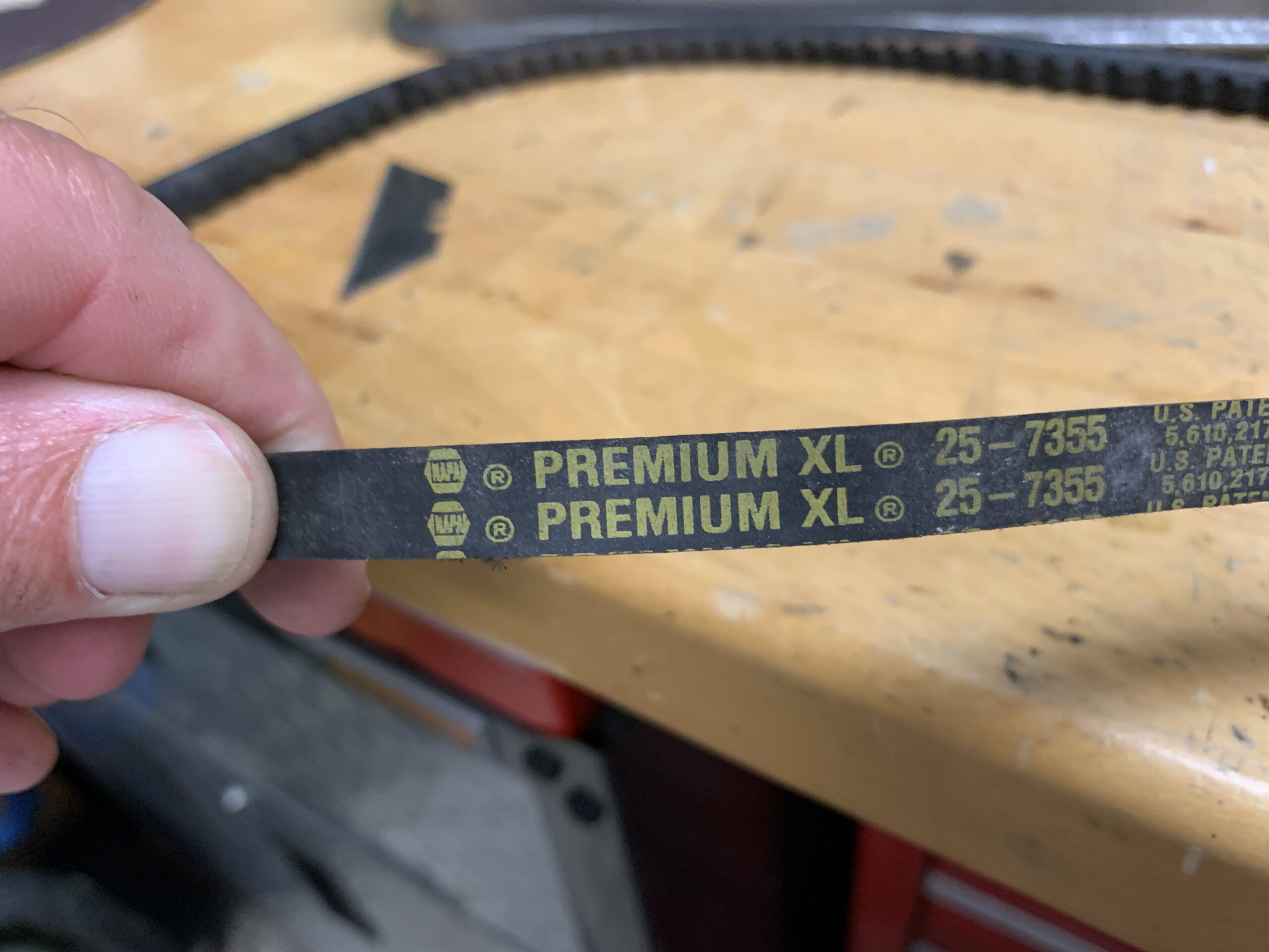
Cogged Fan Belt
The fan was removed for cleaning and reuse. It is held in place with four hex head bolts and a spacer is behind the fan to prevent a blade from striking the breather canister on the timing chain cover.

Cooling Fan
Cooling Fan Spacer
Fan after clean up and reinstallation with painted pulley
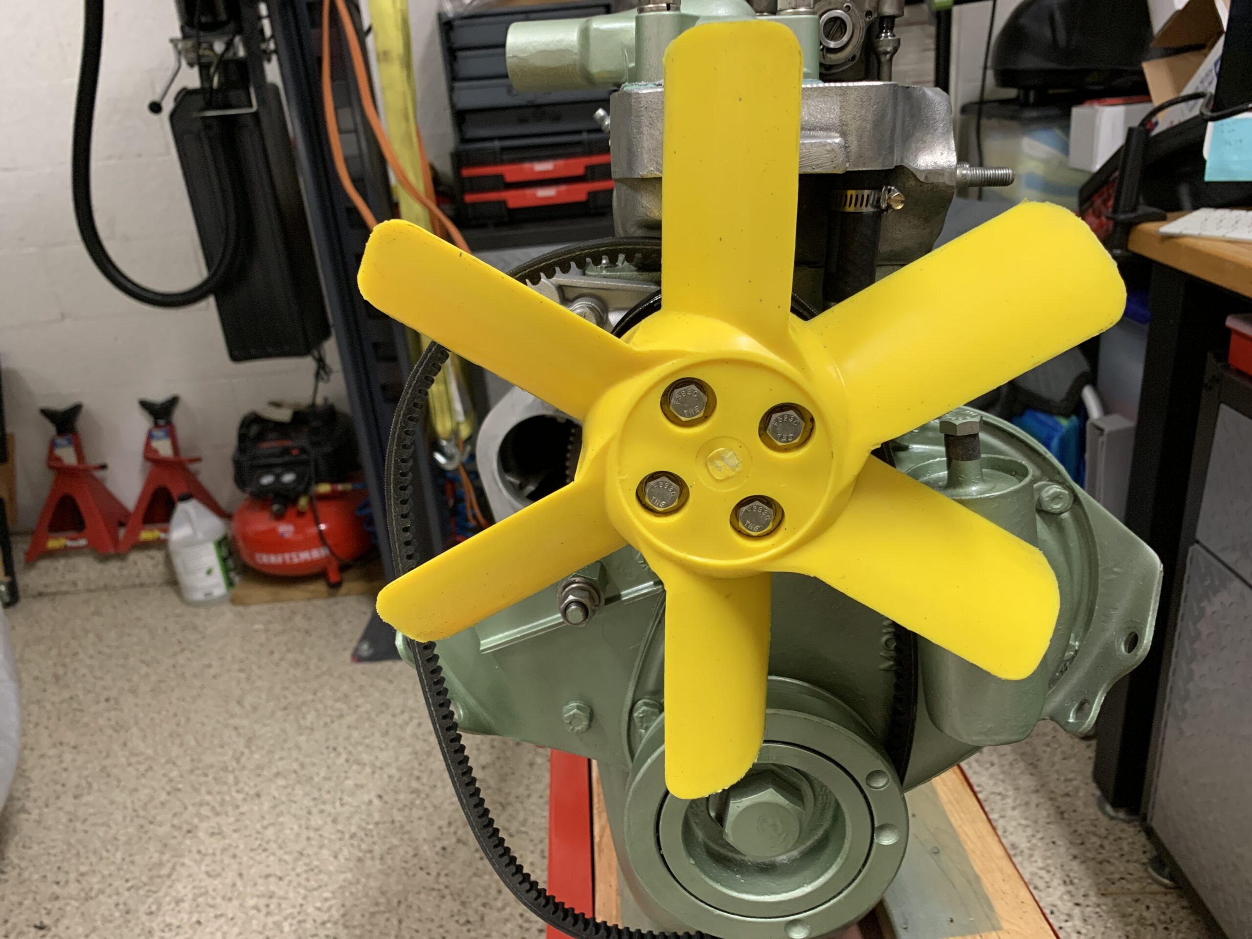
Fan Cleaned and Reinstalled
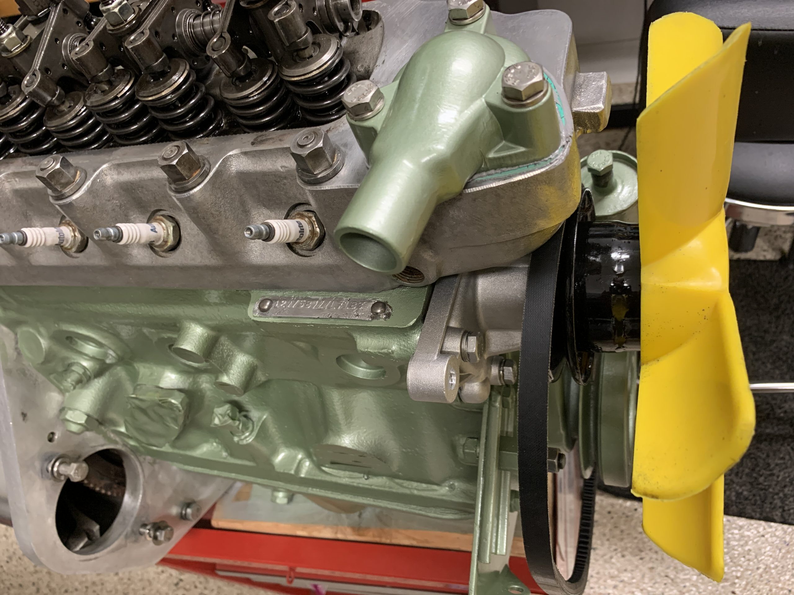
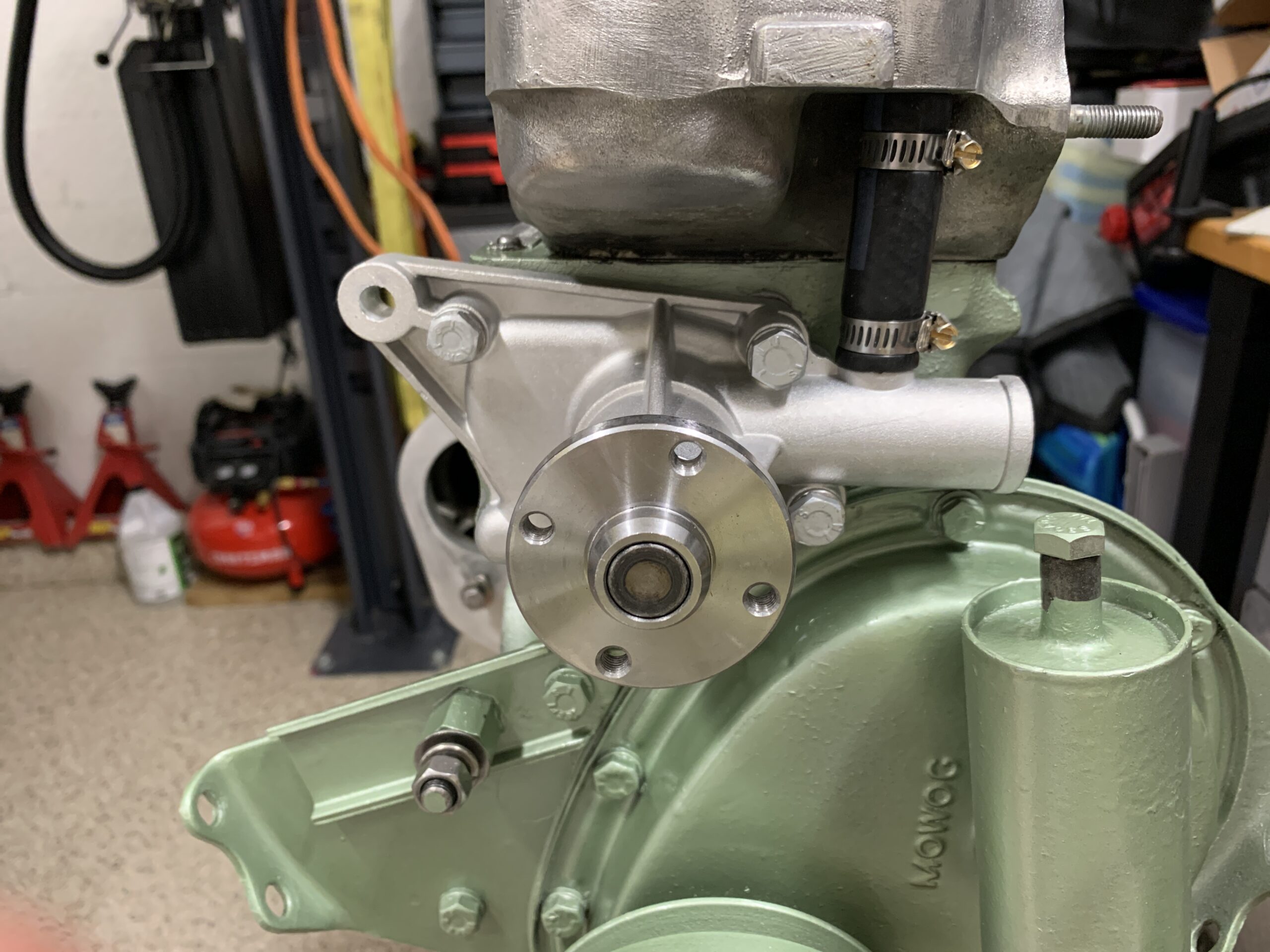
Painted water pump pulley
The water pump pulley was also removed for cleaning and painting with POR-15.
Water Pump Pulley
Since I am in Florida, I thought it was time switch from a 180 degree thermostat to a 160 degree.
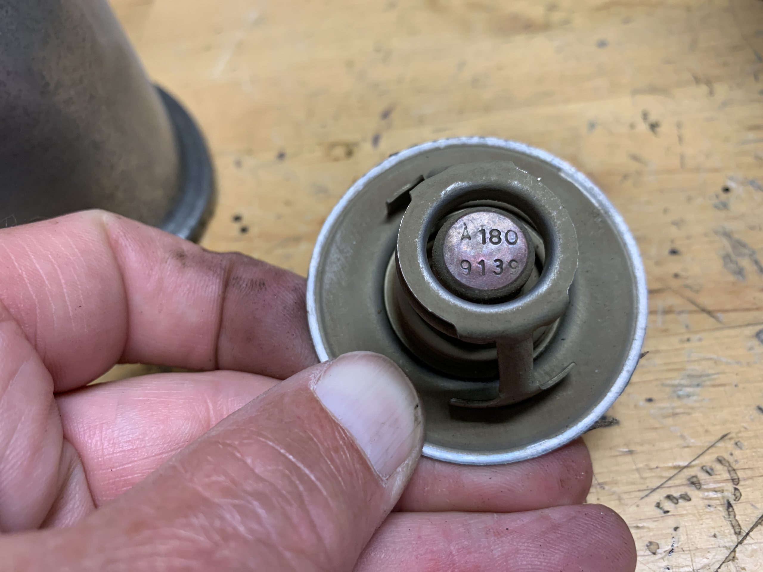
180 degree original thermostat
Also installed a new thermostat housing sourced from Bugeyeguy using Permatex Water Pump & Thermostat Housing Gasket Maker and a new gasket.

Permatex Gasket Maker
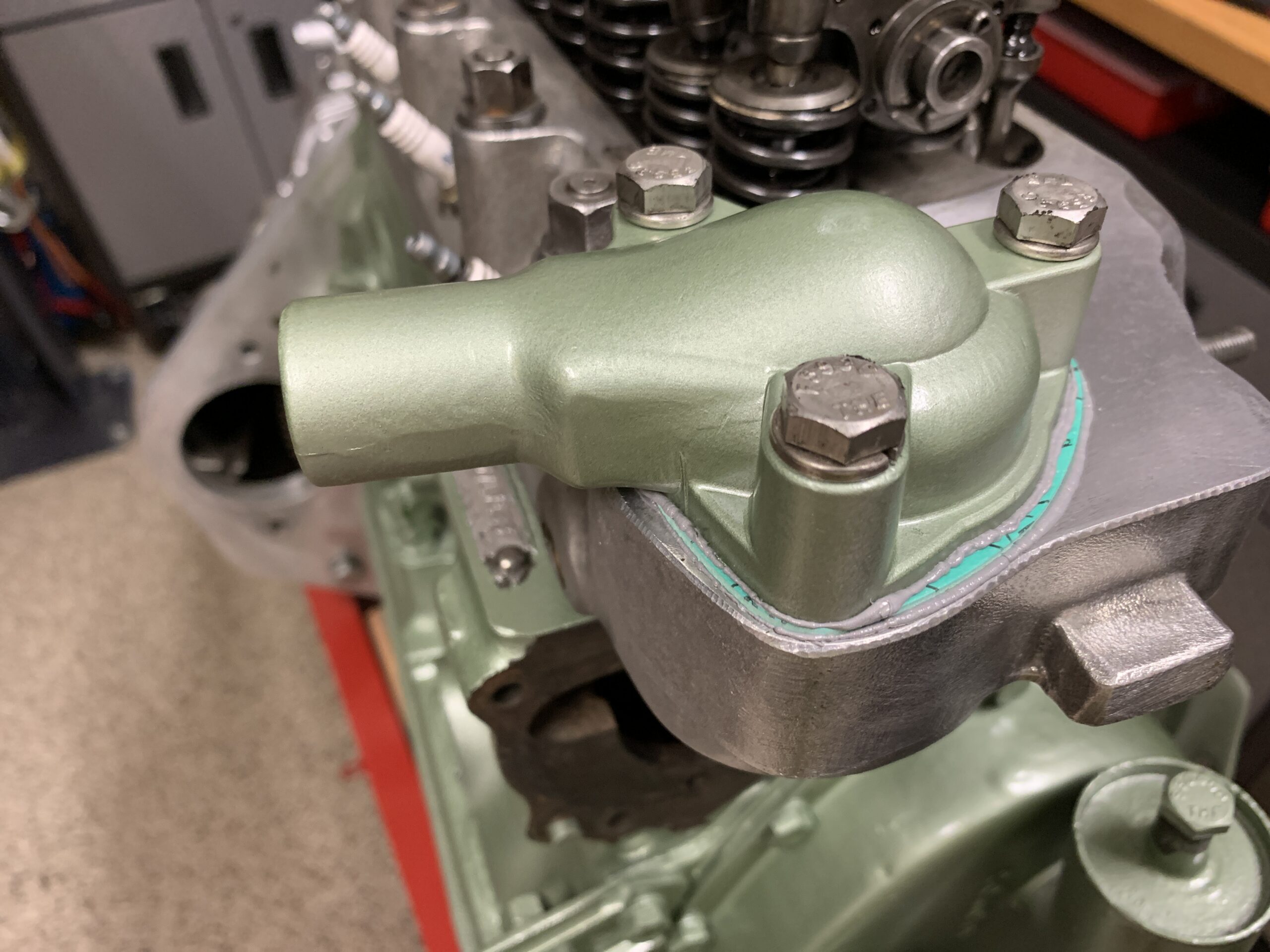
Thermostat Housing
Next, I removed and cleaned the block coolant drain valve.
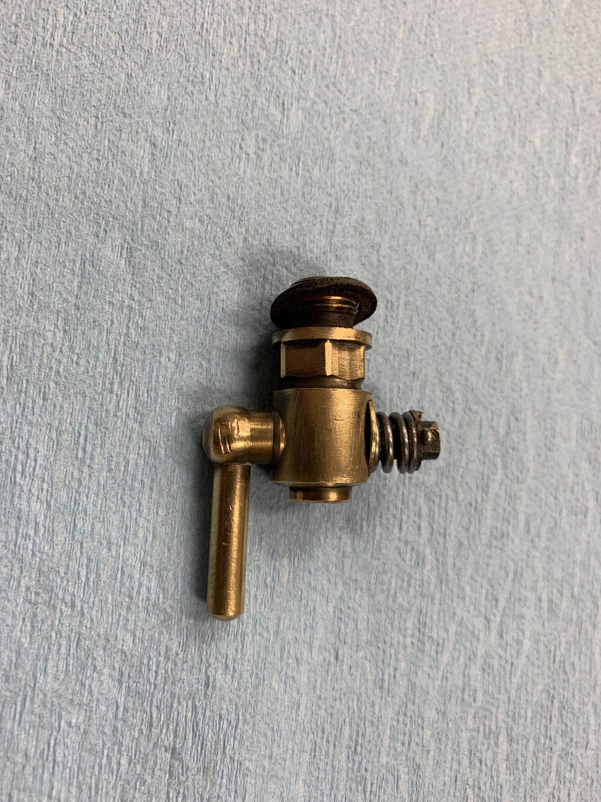
Engine Block Coolant Drain Valve
Removal of the water pump. The lower RH bolt is 1/4” x 28 x 1 1/4”. The lower LH hand bolt is 1/4” x 28 x 2”. The upper right hand bolt is 1/4“ x 28 x 1 3/8”. The upper left-hand bolt is 1/4“ x 28 x 1 7/8”.
Water Pump Removal
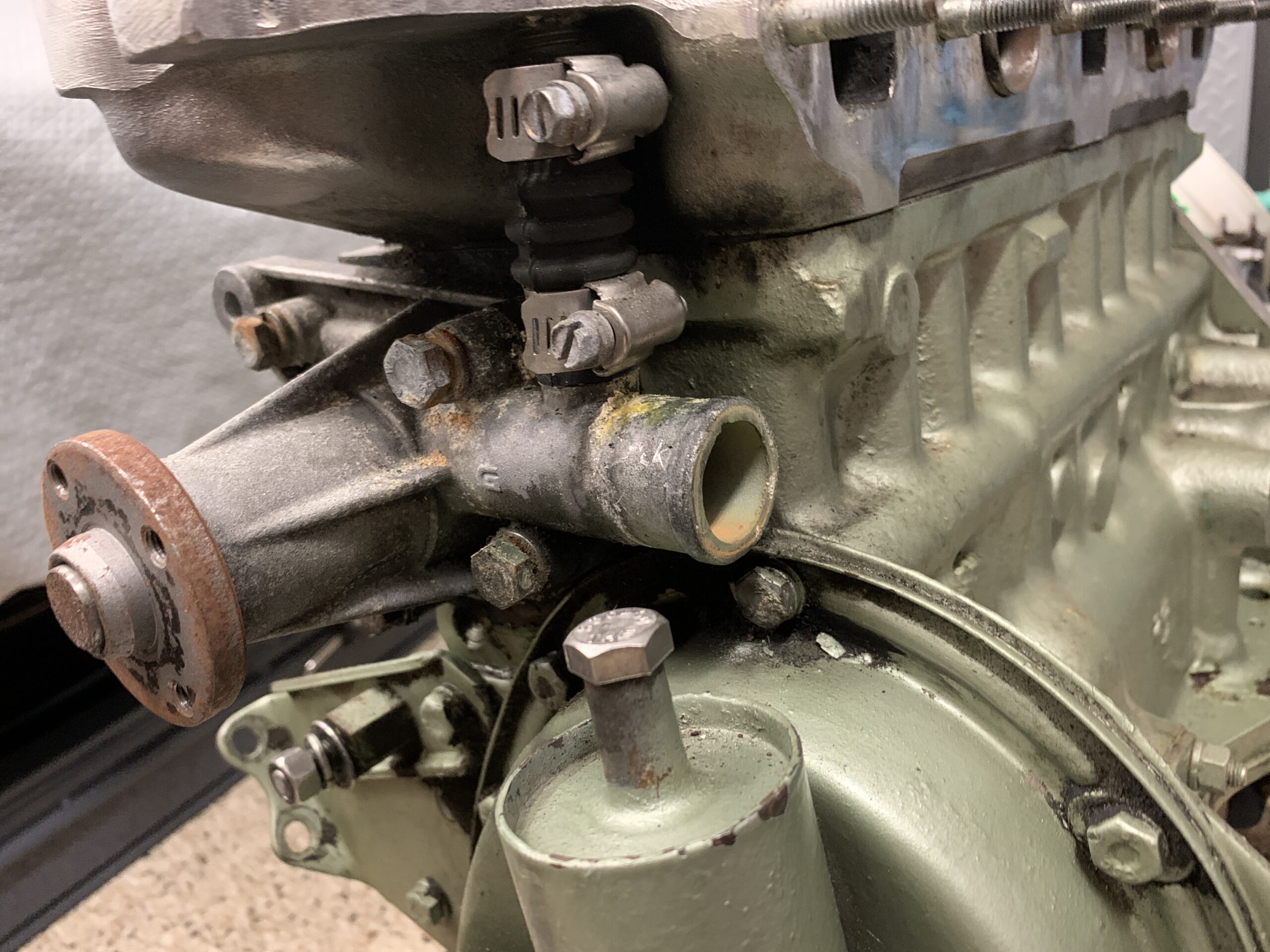
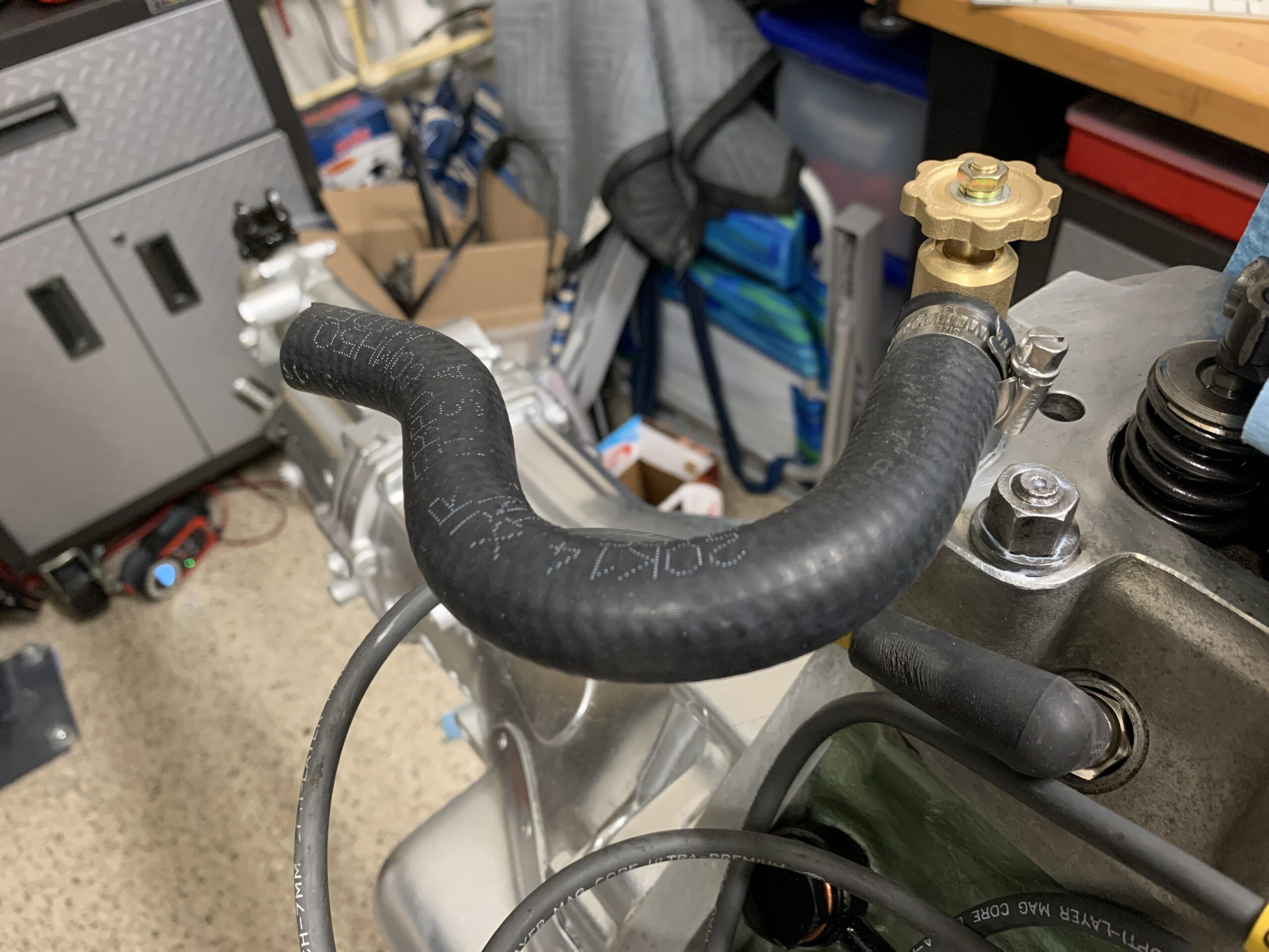
Coolant By-pass hose
After removing the old water pump and cleaning and painting the engine, I installed a new water pump and gasket using the same sealant that was used for the thermostat housing. I installed a stiff (and stronger) by-pass hose to the cylinder head as opposed to the accordion type original hose. With the stiff hose, one must install it as the water pump is fitted, otherwise you cannot get it in place.
New Water Pump and By-Pass Hose Installed
As noted on disassembly care must be taken to install each of the mounting screws appropriately. They vary in length. Again Permatex water pump sealant was used on the new gasket.
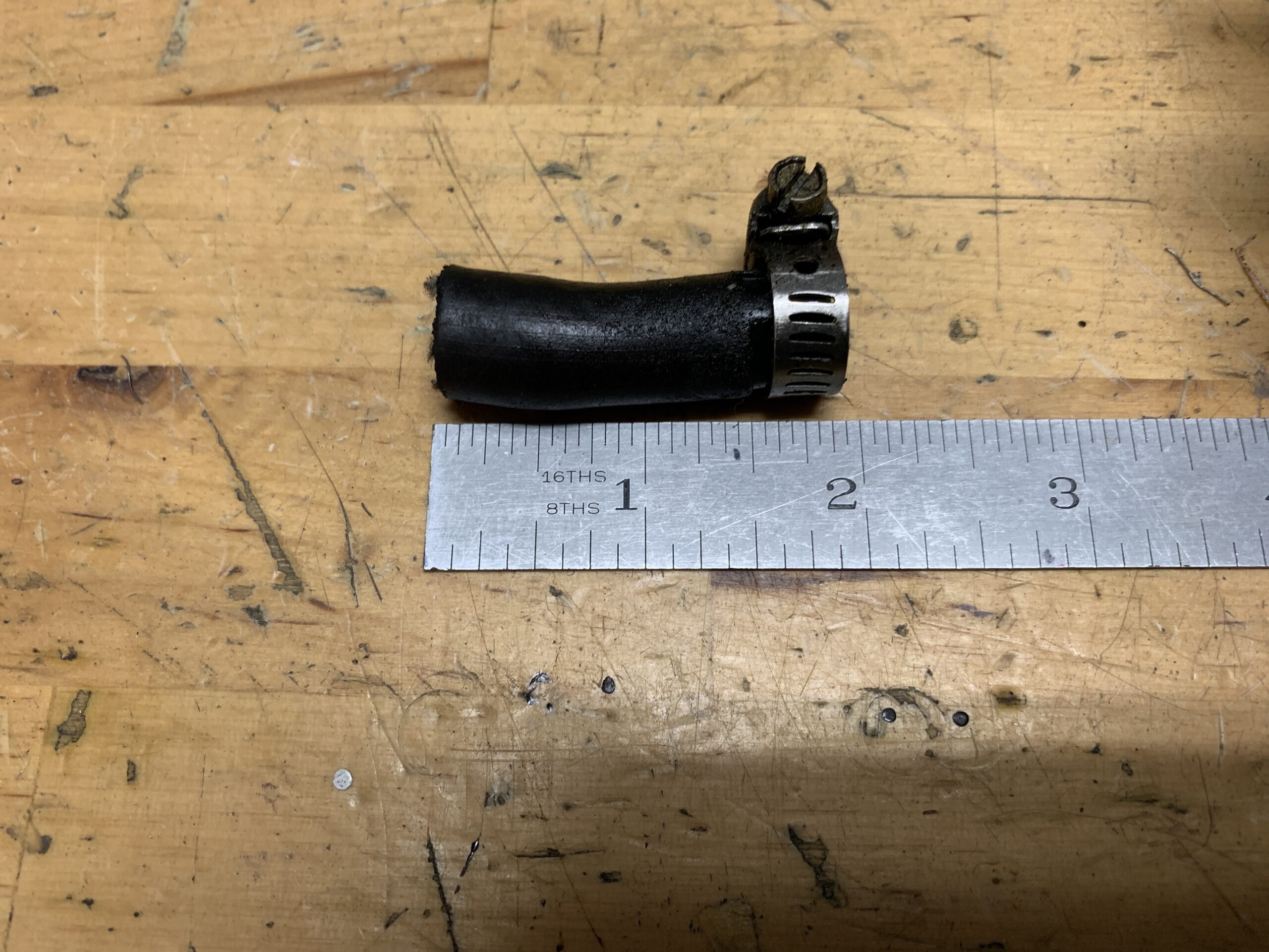
New radiator hoses along with new stainless hose clamps were installed on the motor.

Lower Radiator Hose
Years ago we had installed an electric pusher fan in front of the radiator and while it may be reinstalled at some point in the future, the current plan is to remove it and set it aside since we will be installing a new aluminum radiator sourced from Bugeyeguy.com. Hopefully, the new aluminum radiator will provide improved cooling making the electric fan unnecessary.The fan was attached to the radiator sides with some home made brackets. The wiring will be left in place on the car in case we decide to reinstall the fan.
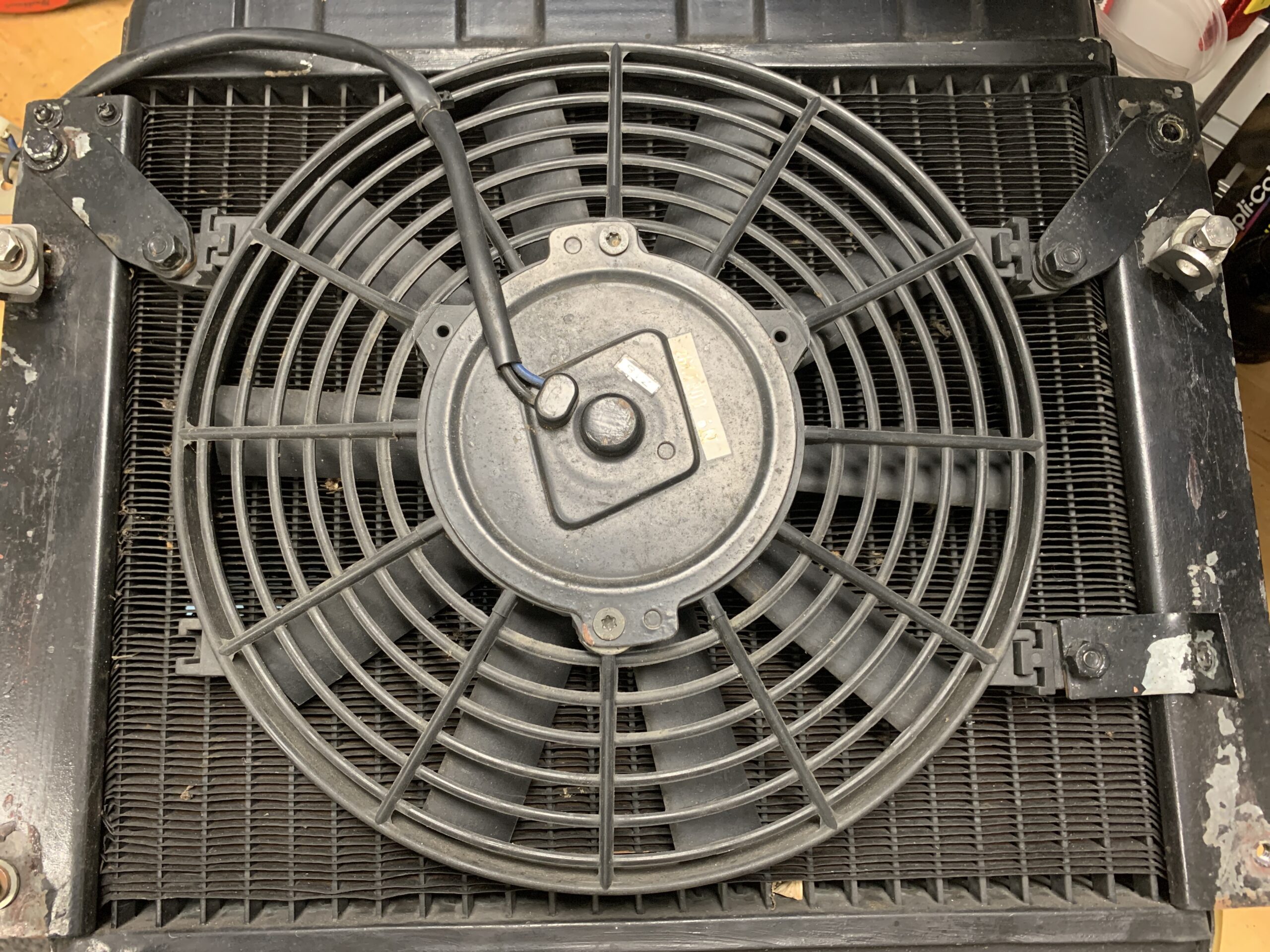
Electric Pusher fan to Remove
The aluminum radiator is nicely made. It is a little tricky to install. It works best to begin with the upper right (passenger side of the car) mounting point first, then the lower right, followed by the upper left mount and finally the lower left mount. This sequence seemed to work pretty well.
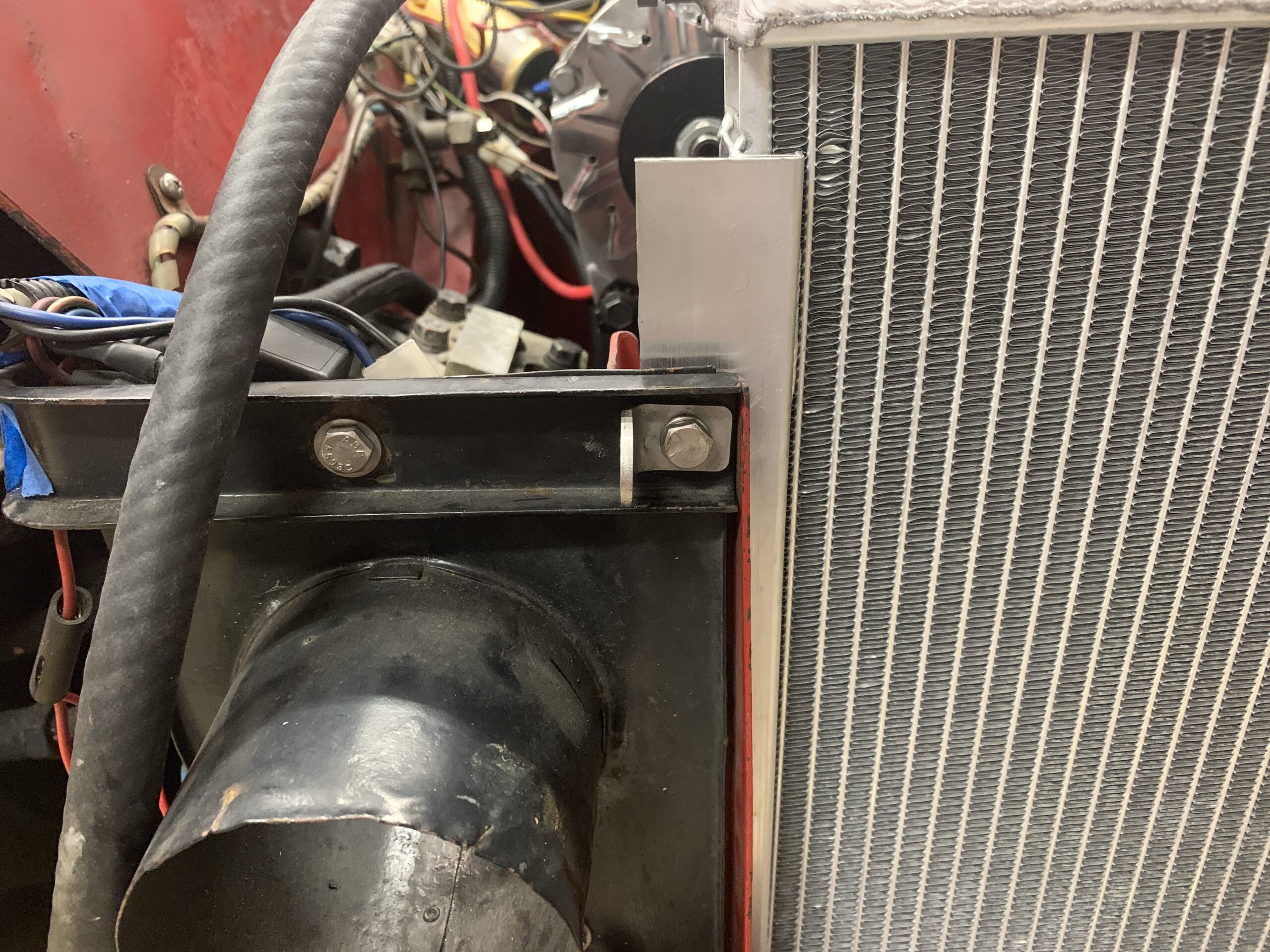
aluminum radiator upper right hand mount
The radiator has a bung for a temperature sender, that will not be used since the temperature center is in the cylinder head. New upper and lower radiator hoses were purchased and installed. The radiator came with a new 5lb. cap. The cap is smaller than is typical so an extra was ordered to have one on hand.

Aluminum Radiator with new rubber hoses and 5lb. radiator cap
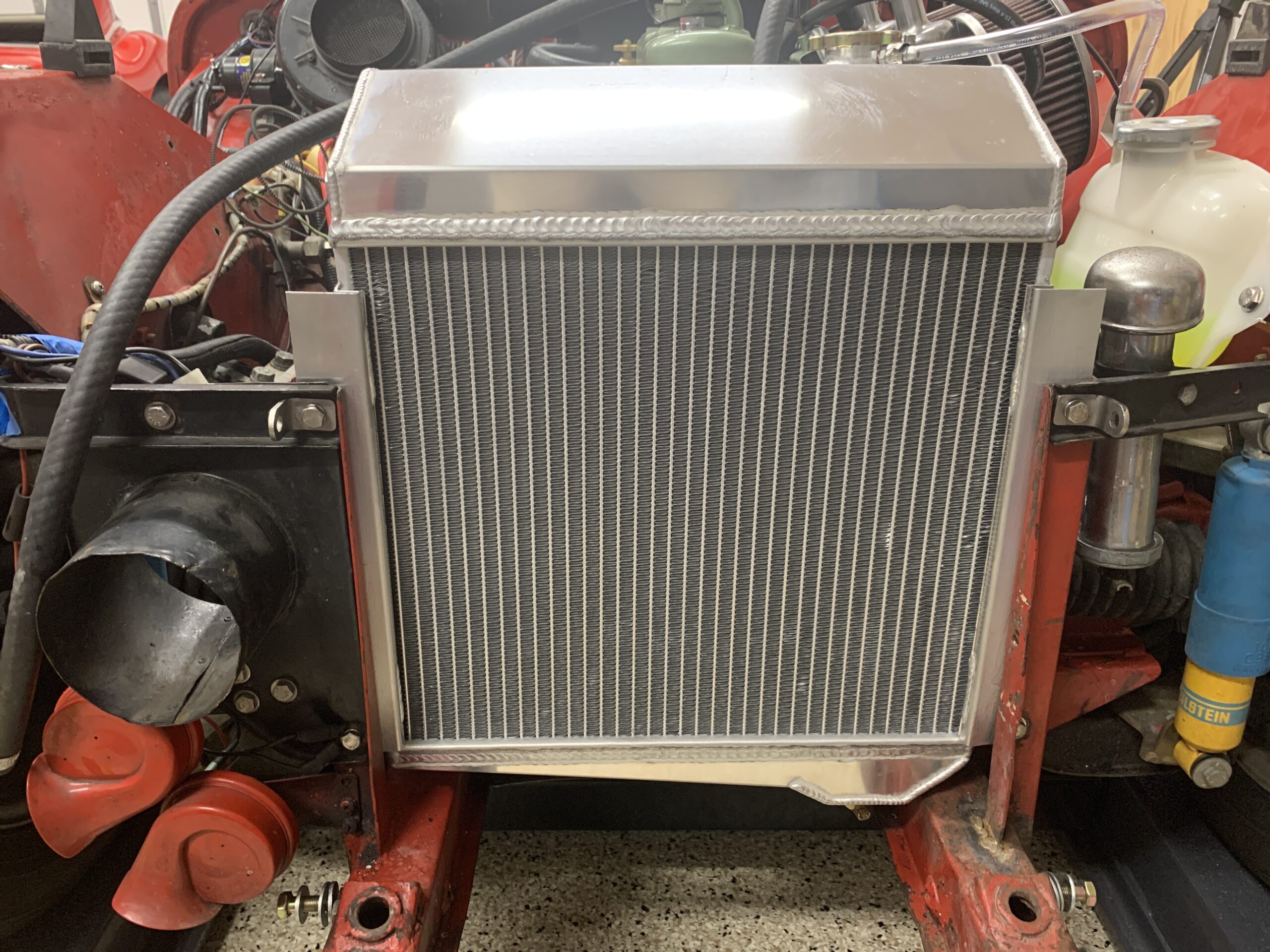
aluminum radiator installed with bonnet catch brackets
A new overflow tank was added. This photo shows the clear hose to the tank from the radiator.
Aluminum Radiator Oveflow hose to tank
To take advantage of holes that were already drilled into the chassis/body a rather strange looking cooling overflow tank bracket was fabricated to secure the tank to the LH wheel arch. This was painted and installed.

Coolant Overflow Tank Mounting Bracket

Coolant Tank Installed and filled
The radiator was filled with Prestone 50/50 coolant.
Electrical
A new battery from Batteries Plus was installed.
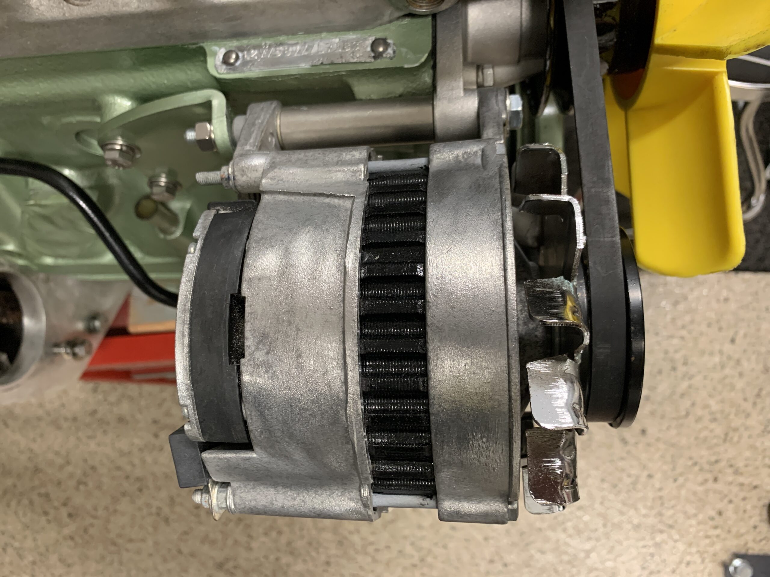
The alternator had some oxidation issues and this was removed as much as possible and a lubricant protectant called TW 25B (used to protect firearm bare metal) was applied.
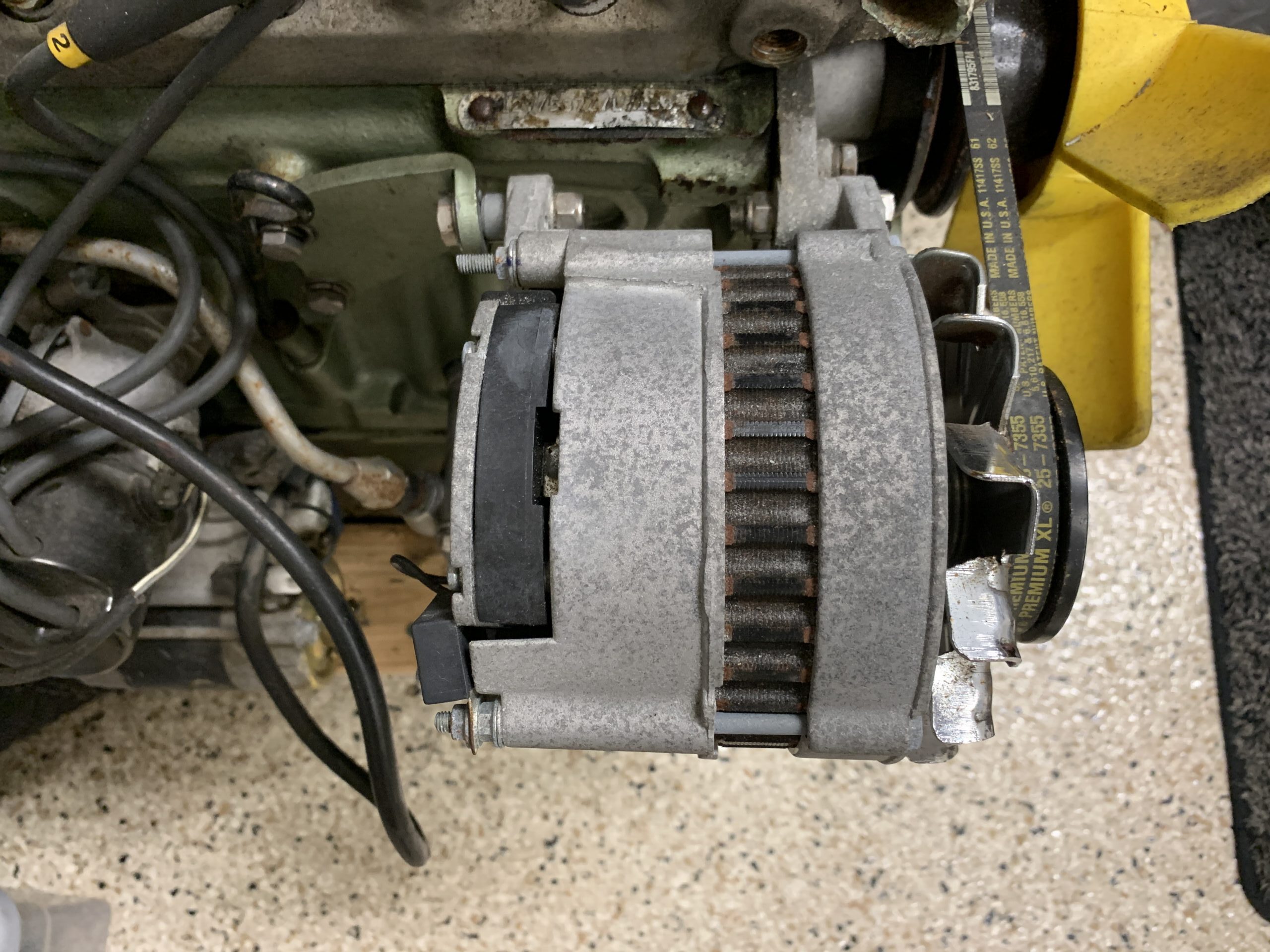
Bugeye Alternator – Before
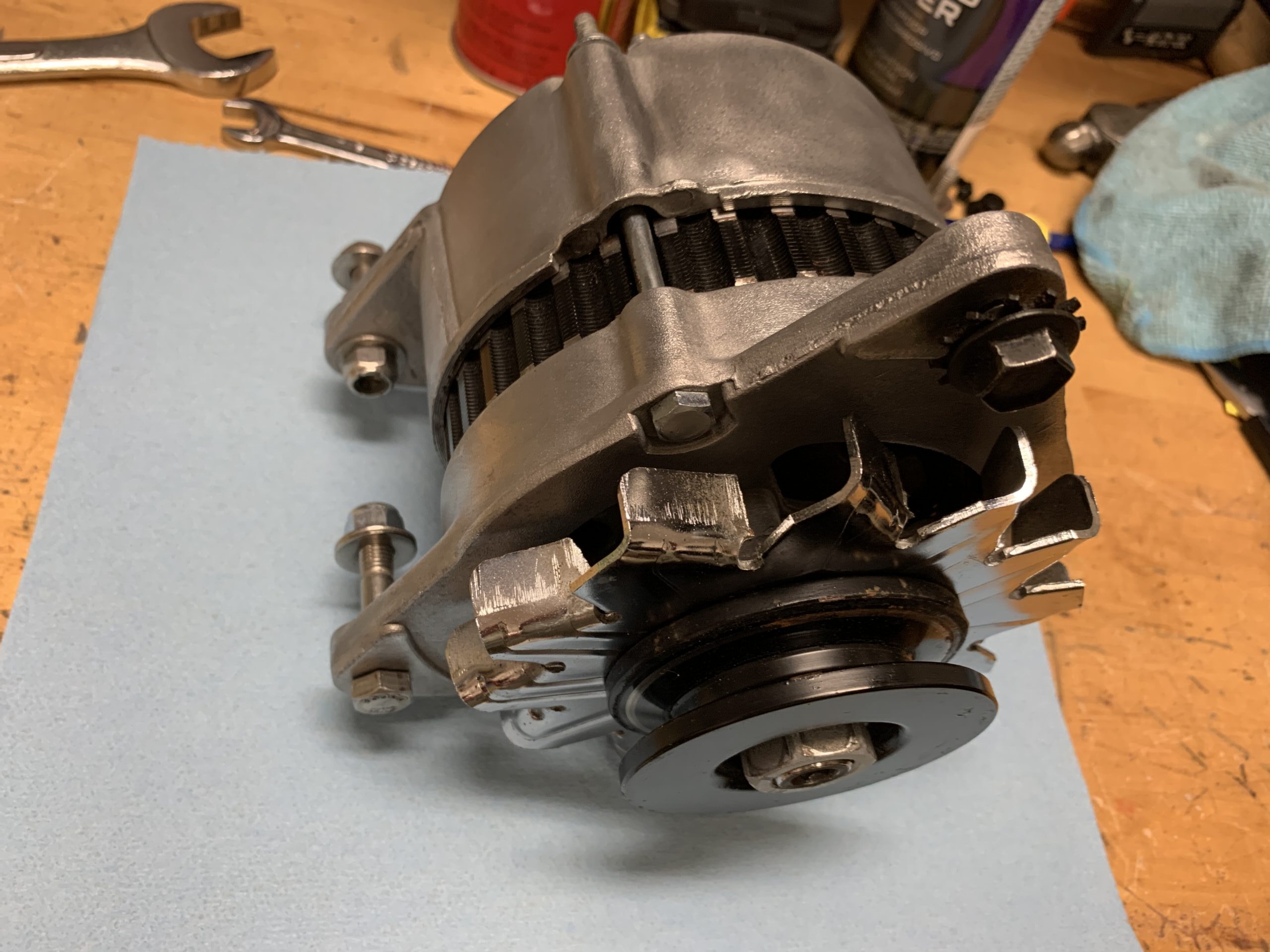
Bugeye Alternator – After
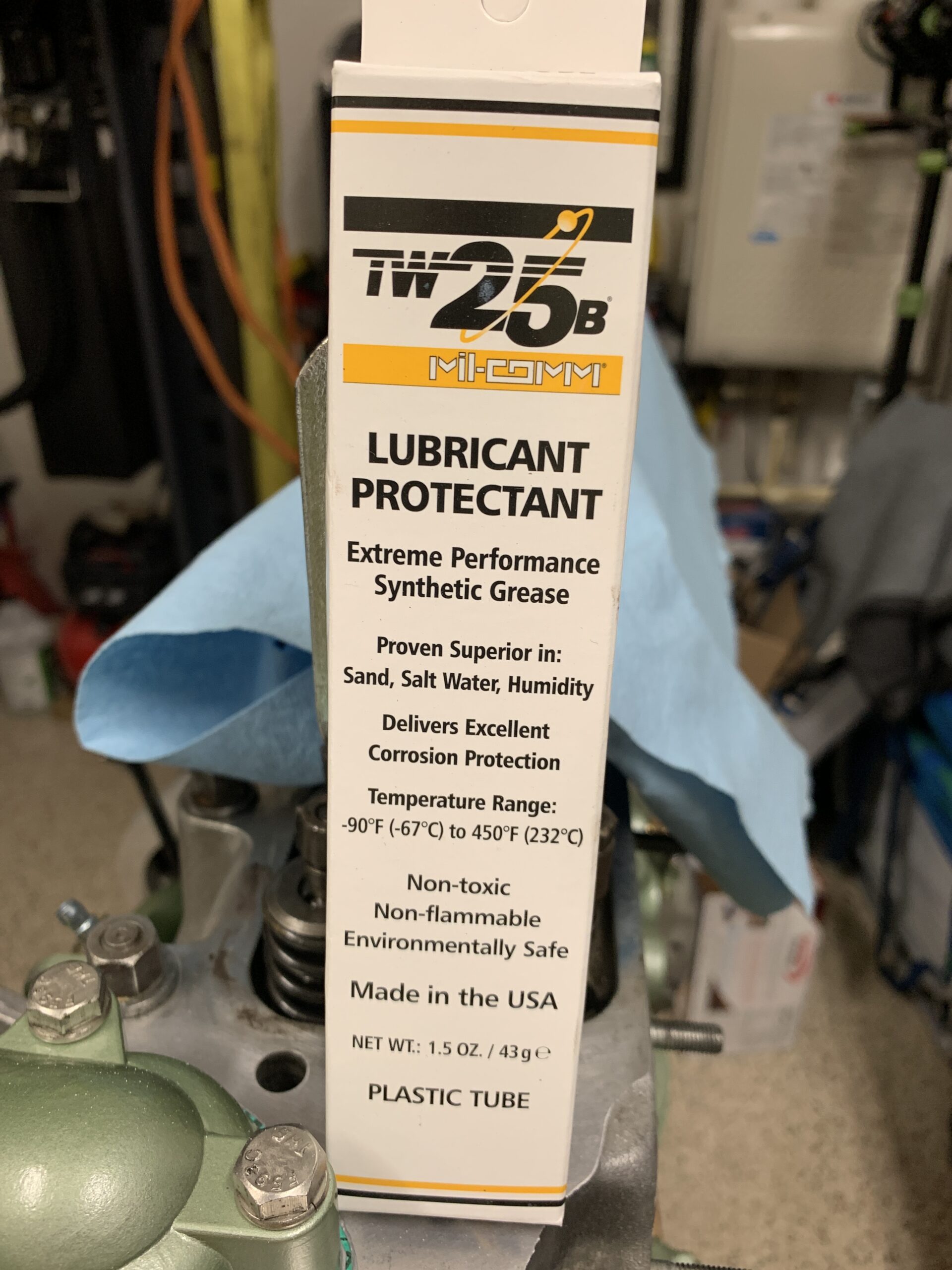
LUBRICANT TW 25B
Rather than having two bolts for the left and right ears of the alternator, a single long bolt and a stainless bushing have been added to enhance the stability of the mounting.
Bugeye Alternator with new Mounting Bushing
The alternator mounting bracket was removed and painted.

Bugeye Alternator Bracket Painted
As was the alternator adjustable swing bracket. Painted with POR-15.

Alternator Swing Bracket, Dip Stick and Water Pump Pulley Painted
The cable to the starter from the solenoid was pretty old so it will be replaced with a new cable sourced from MiniMania.

Starter Cable to be Replaced
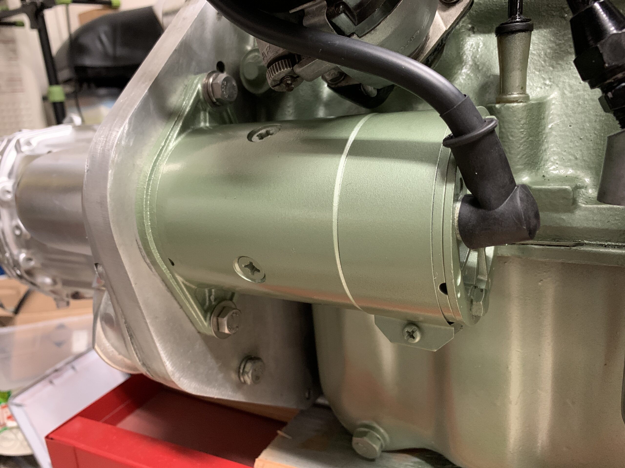
The gear reduction, high torque, starter was cleaned, but after painting a new original-type bendix starter was installed.
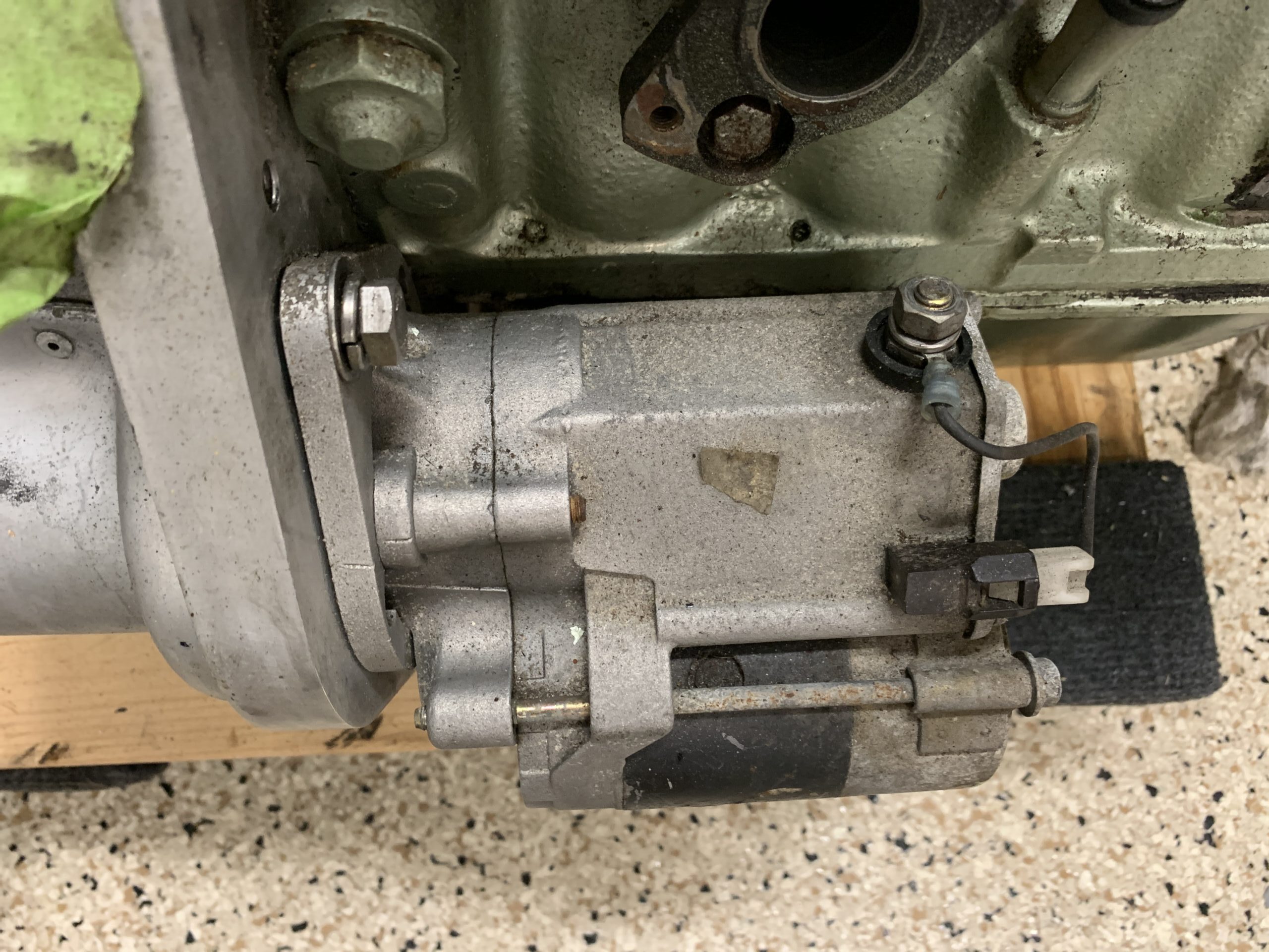
High Torque Starter – Before

High Torque Starter – After
New Starter and Cable
The windscreen washer pump was not working. The hoses were repaired or replaced and the Tutor Reservoir Bottle was cleaned and tested for operation. The electrical connections were fine it just turned out that one of the hoses was clogged with crystalized cleaner fluid.

Windscreen Washer Pump
I had previously installed LED lights in both the front and rear of the car; however, the flashers were not working because I had not installed an electronic flasher canister. My Dad sourced one from Bugeye Guy and installed it, including reattaching the connections for the Radio Shack beeper to alert that the flashers are still on. Everything now works as it should.
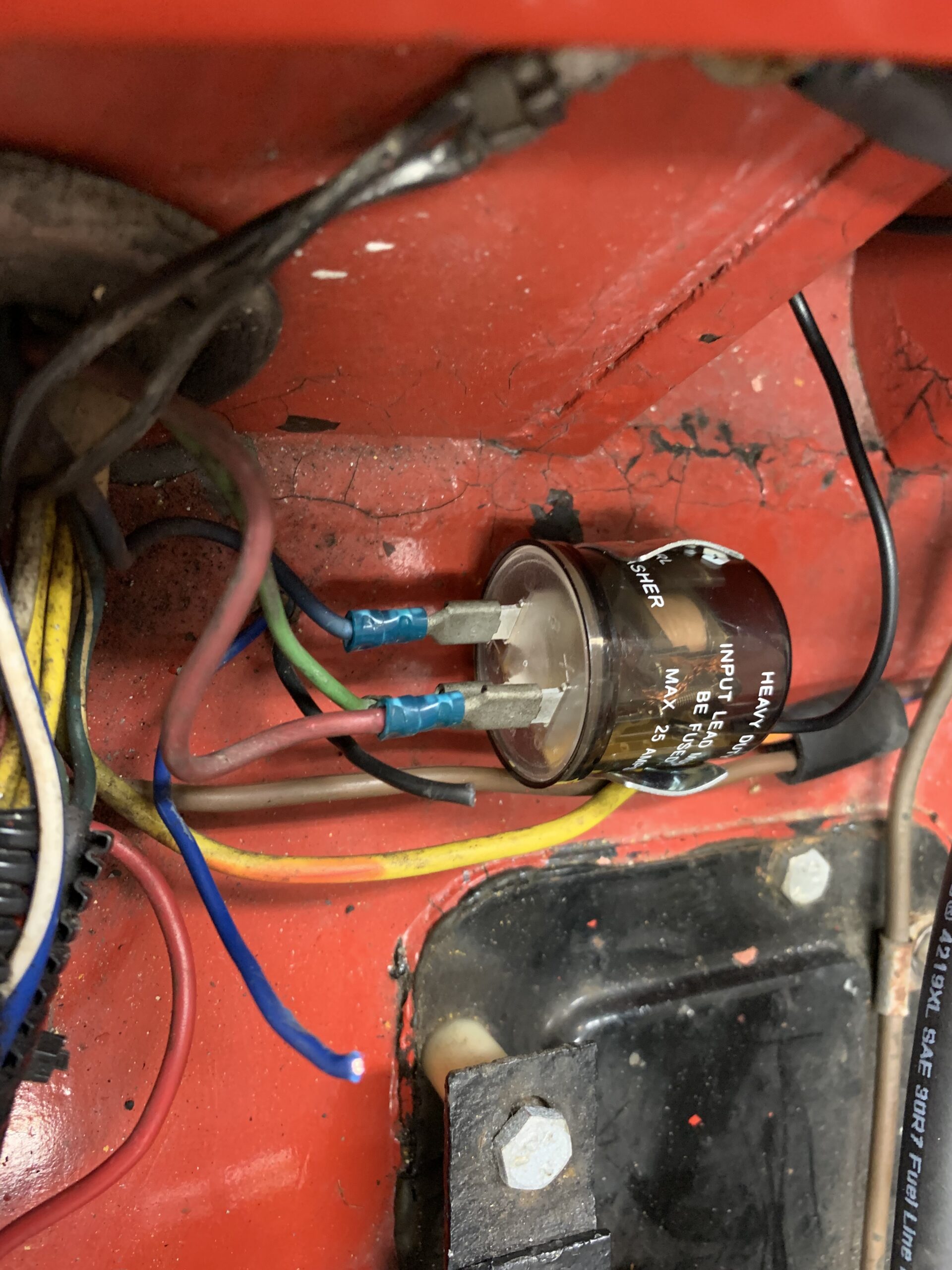
Electronic Flasher Can
The black wire from the beeper is paired with the blue wire from the turn signal switch into a joint terminal to the LED flasher.
The blue wire from the beeper is paired with the red wire from the turn signal switch into a joint terminal to the LED flasher.
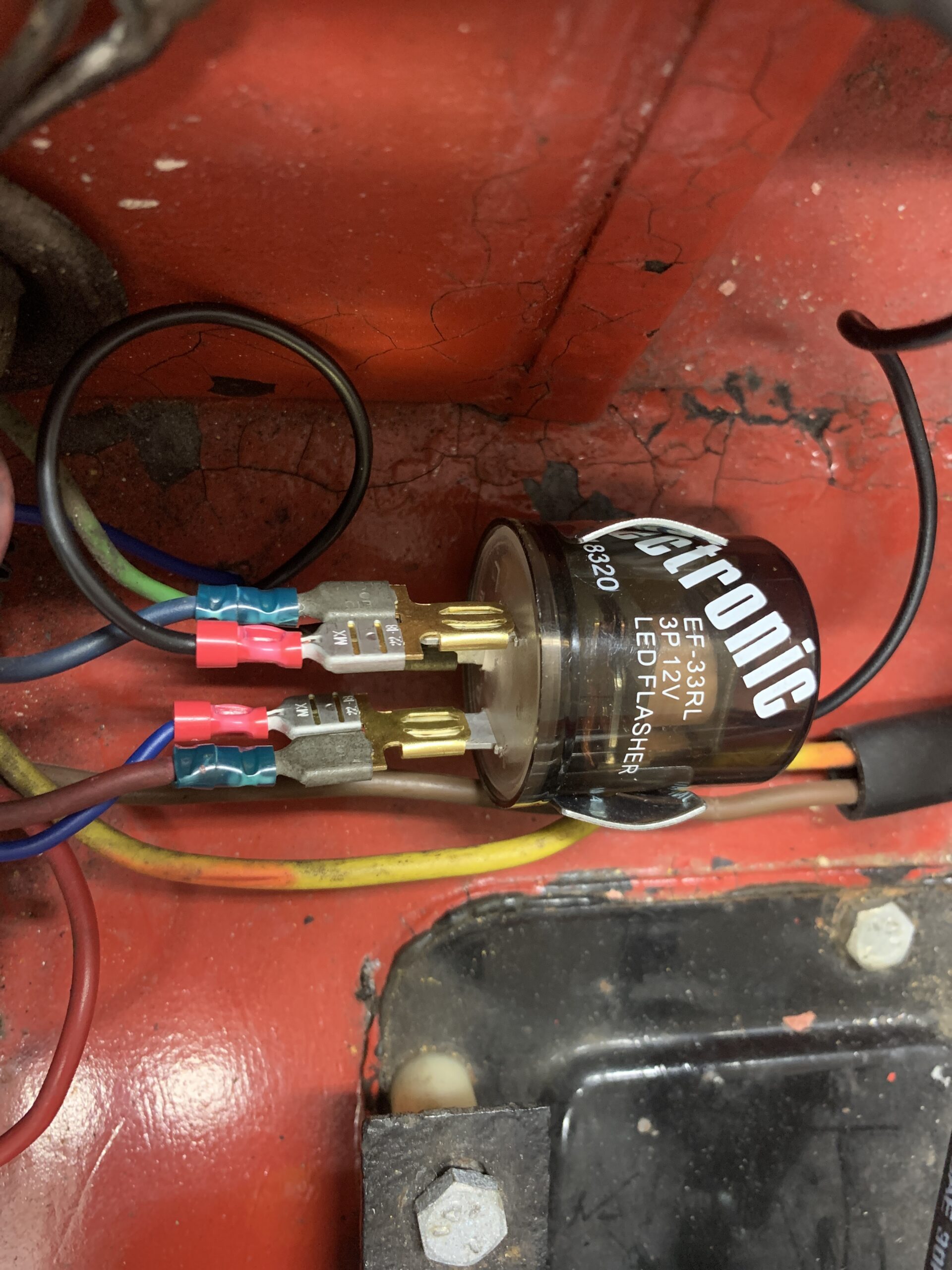
Beeper Wiring Connections
The old coil bracket was rusty and looked out of place on the fresh engine so a new chrome ignition coil bracket was installed.

Ignition Coil Bracket
Engine
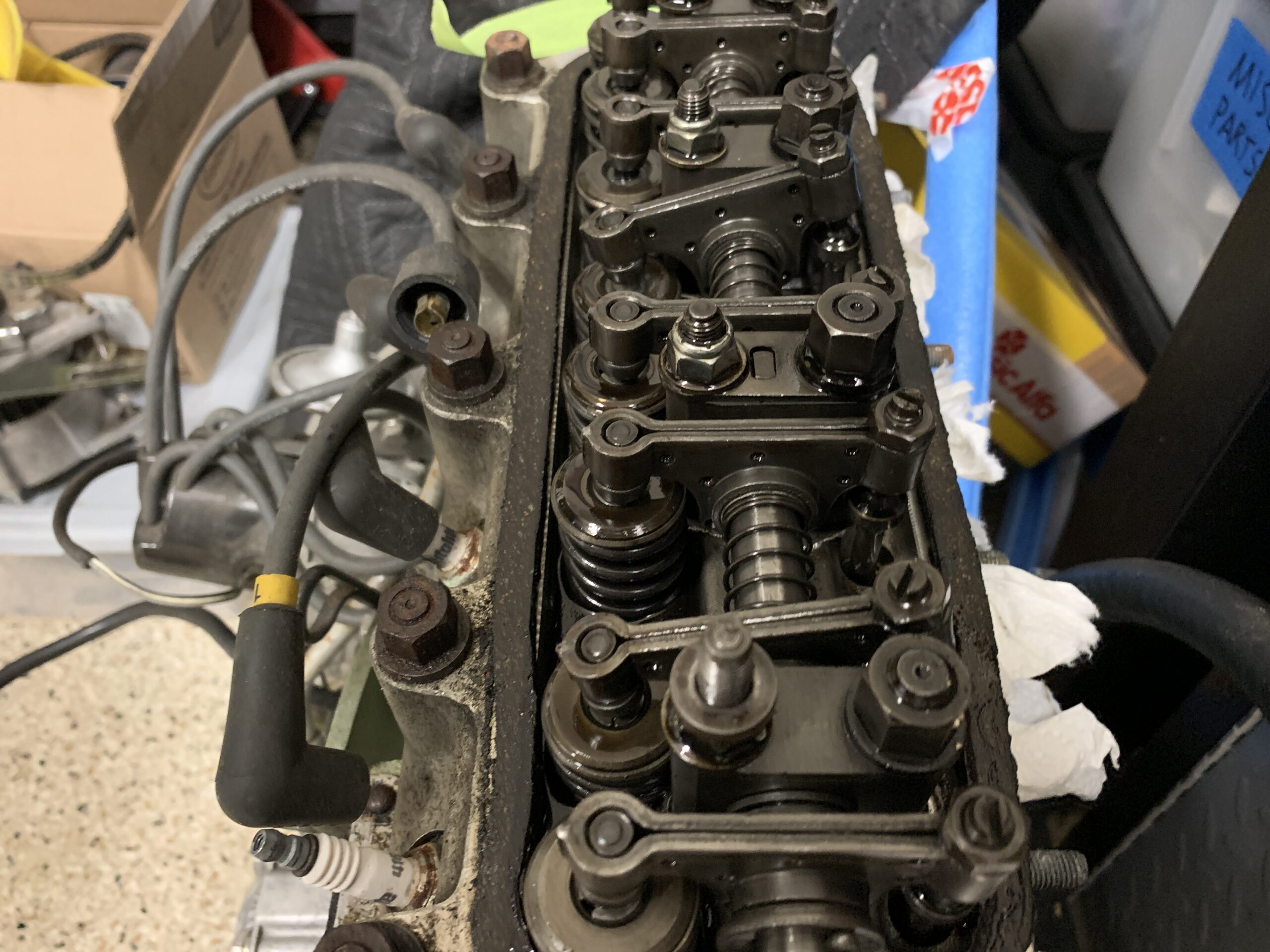
The rocker cover was removed. It was pretty badly tarnished and will be replaced with a new one. The Mounting hardware was also in bad shape so the3 chrome nuts and washers will also be replaced.
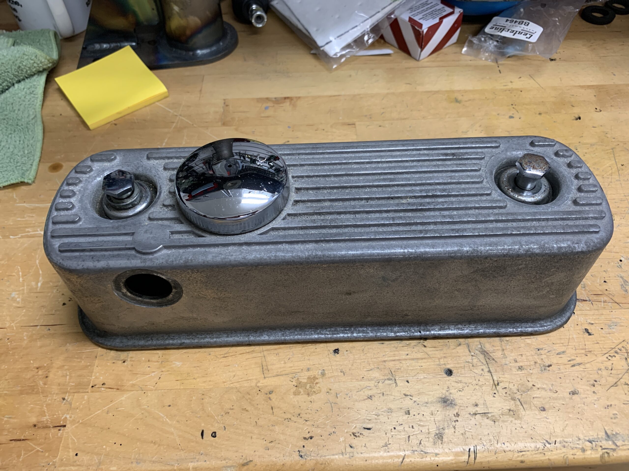
Used Rocker Cover
Although an original rocker cover will probably be used for the engine, a new alloy cover was prepared in case we change our minds. Permatex Red RTV high temp silicone Gasket Maker was used to glue the Gasket Innovations silicone valve cover gasket to the alloy rocker cover. Moss Motors part number 296-007. Gasket Innovations # GBM-AAL.

Silicone Rocker Cover Gasket
Installed new chrome valve cover bolts and washer from Spridget Mania #SAC71L along with black polyurethane sealing washers also from Spridget Mania #WB6 along with a new vented cap.

Rocker Cover Fastener Hardware
The new alloy rocker cover ready to use if we decide to put it on the car.
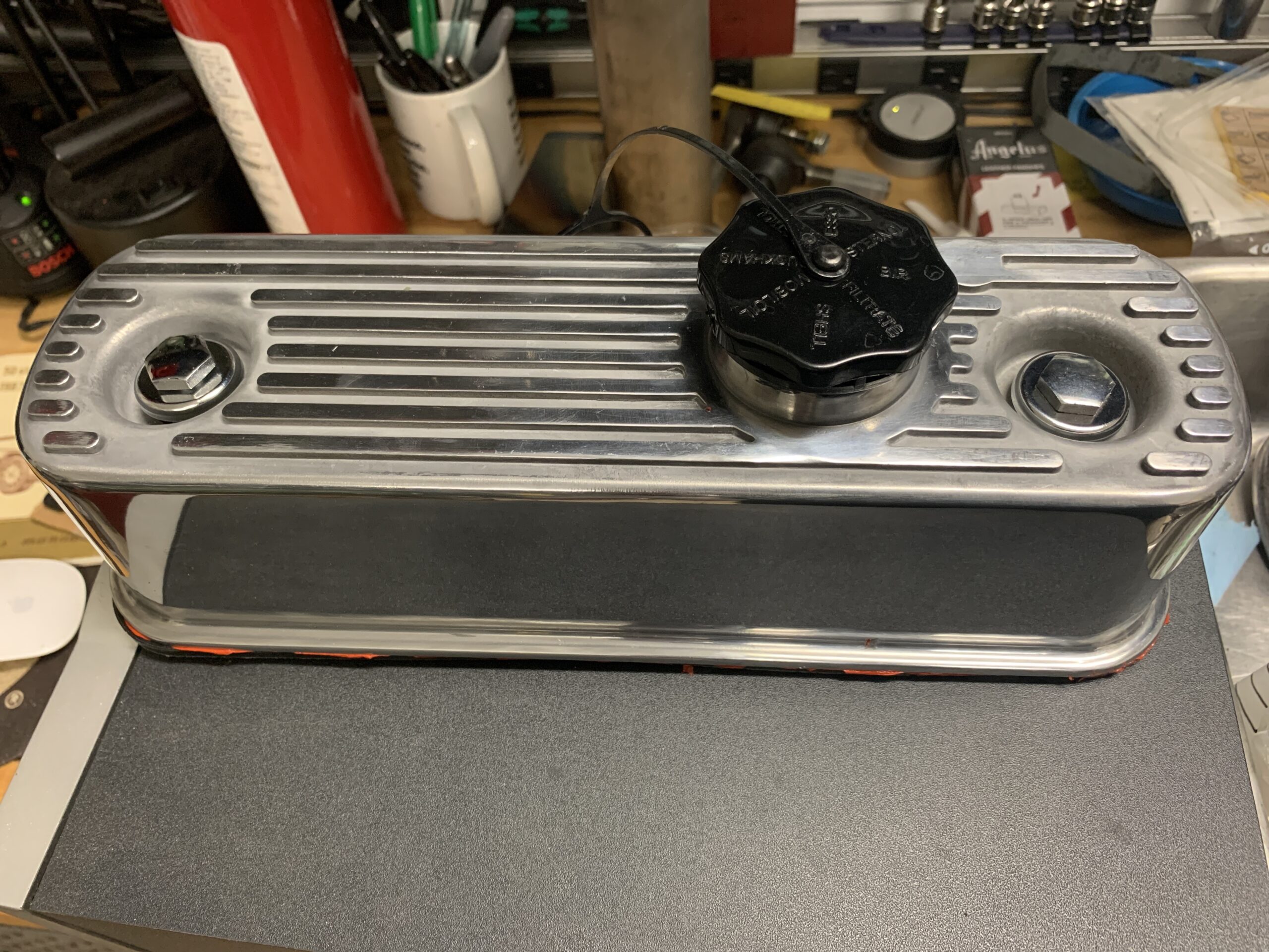
New Alloy Rocker Cover
The Oil Feed Line was removed for cleaning and painting:
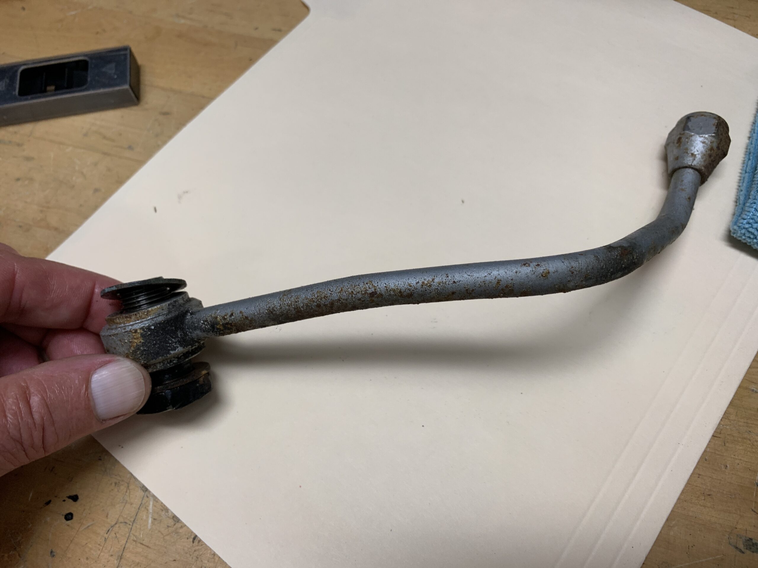
Oil Feed Pipe
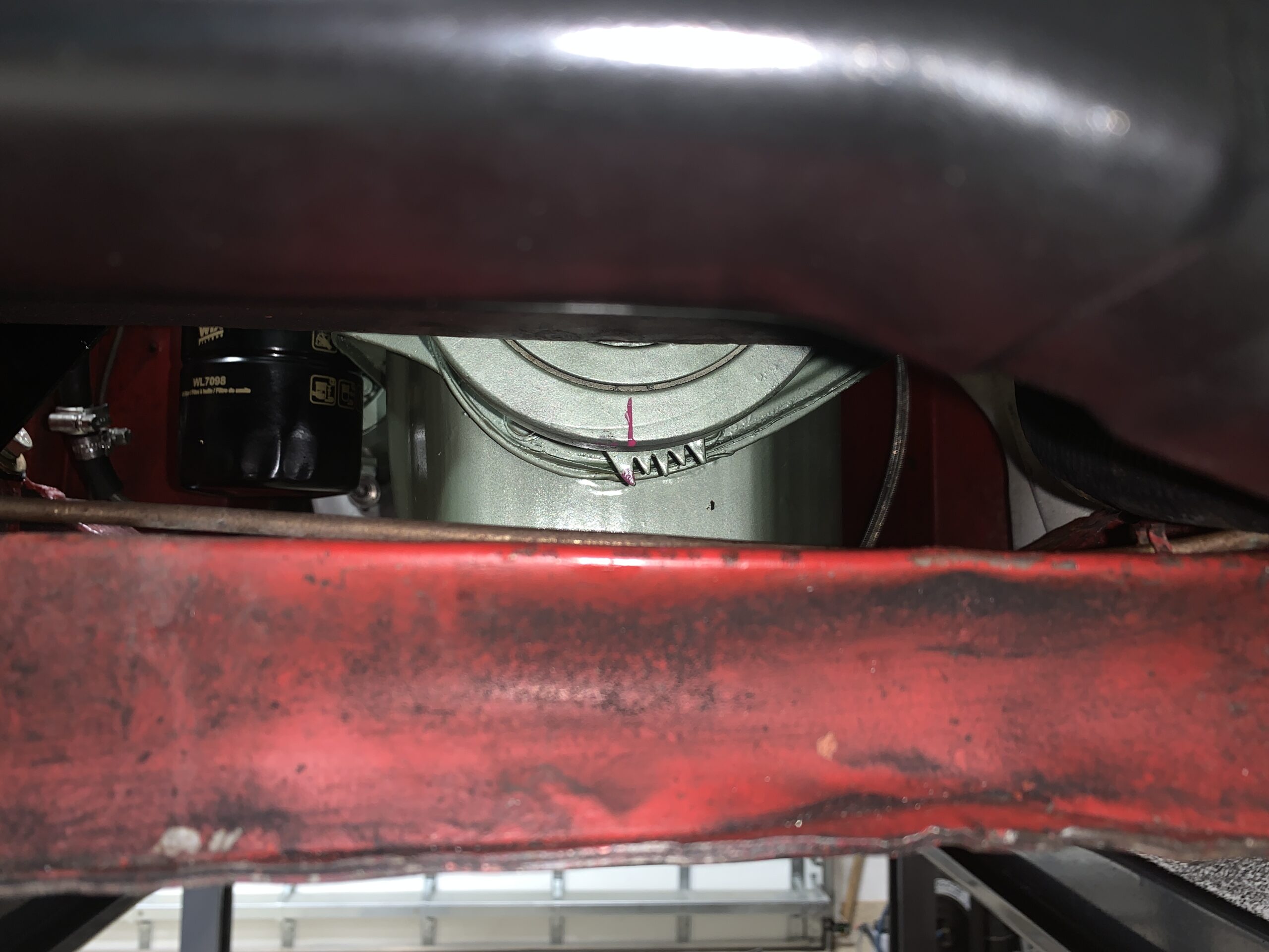
As was the oil filter housing for the spin on oil filter:
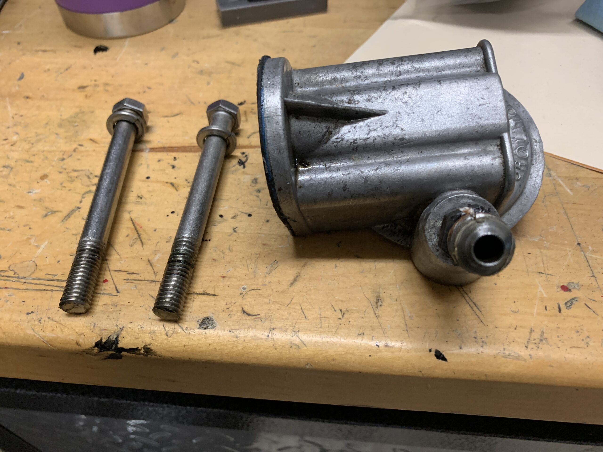
Oil Filter Housing and Mounting Bolts
The housing was cleaned and polished and the lubricant protectant was applied as a coating.
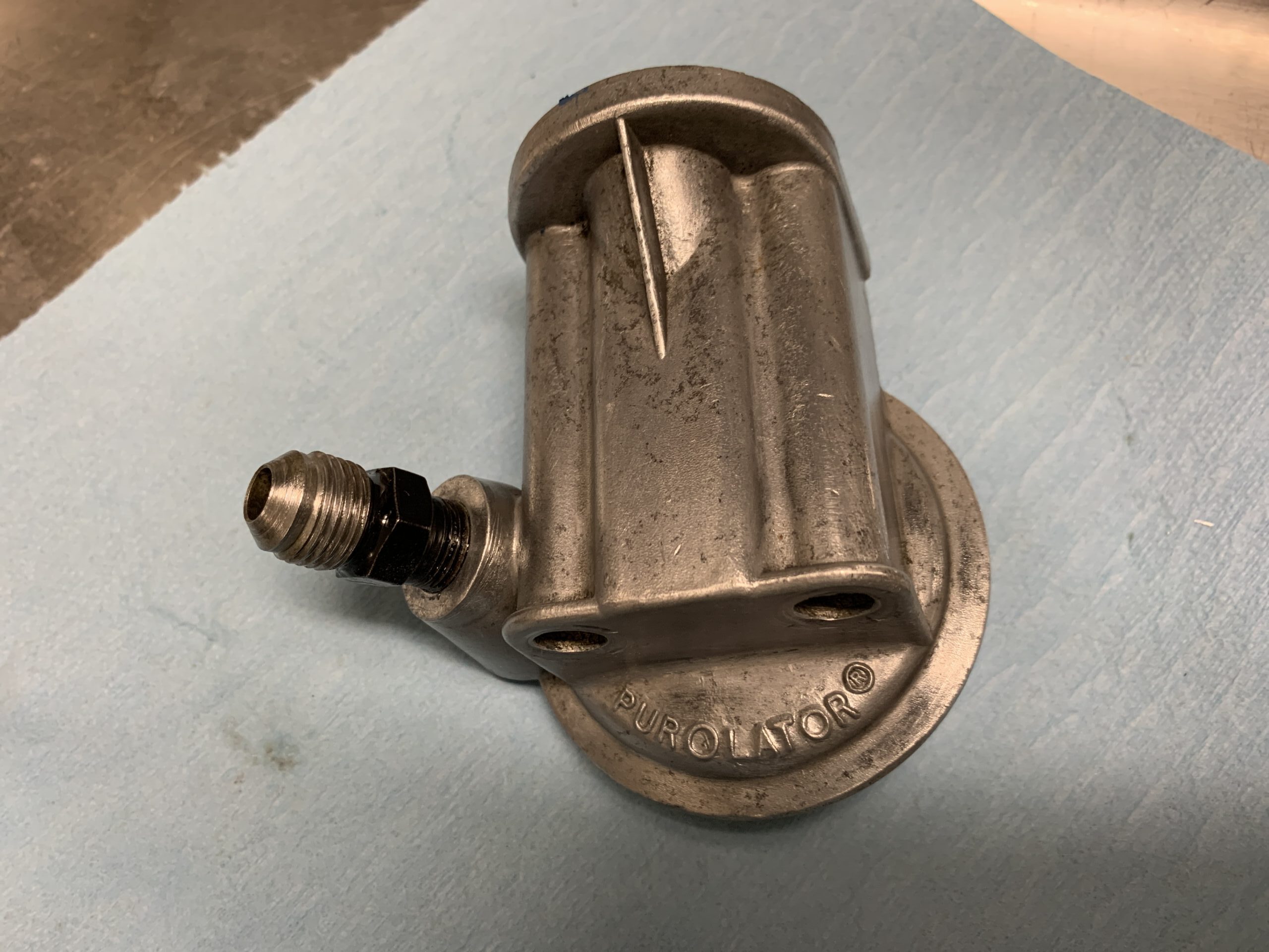
Oil Filter Housing Cleaned and Polished
The oil filter removed from the engine was a Mobil One M1-102. However, a WIX spin-on oil filter WL 7098, sourced from MiniMania was used upon rebuild.
Installed the Oil Feed line with two new copper crush washers along with the Purolator spin on oil filter housing and filter. Blue hylomar sealant was used on the housing gasket to the block. The filter is not screwed on tight and will need to be half filled with oil after the engine is installed in the car.

Oil Pipe, Filter Housing and Filter Installed
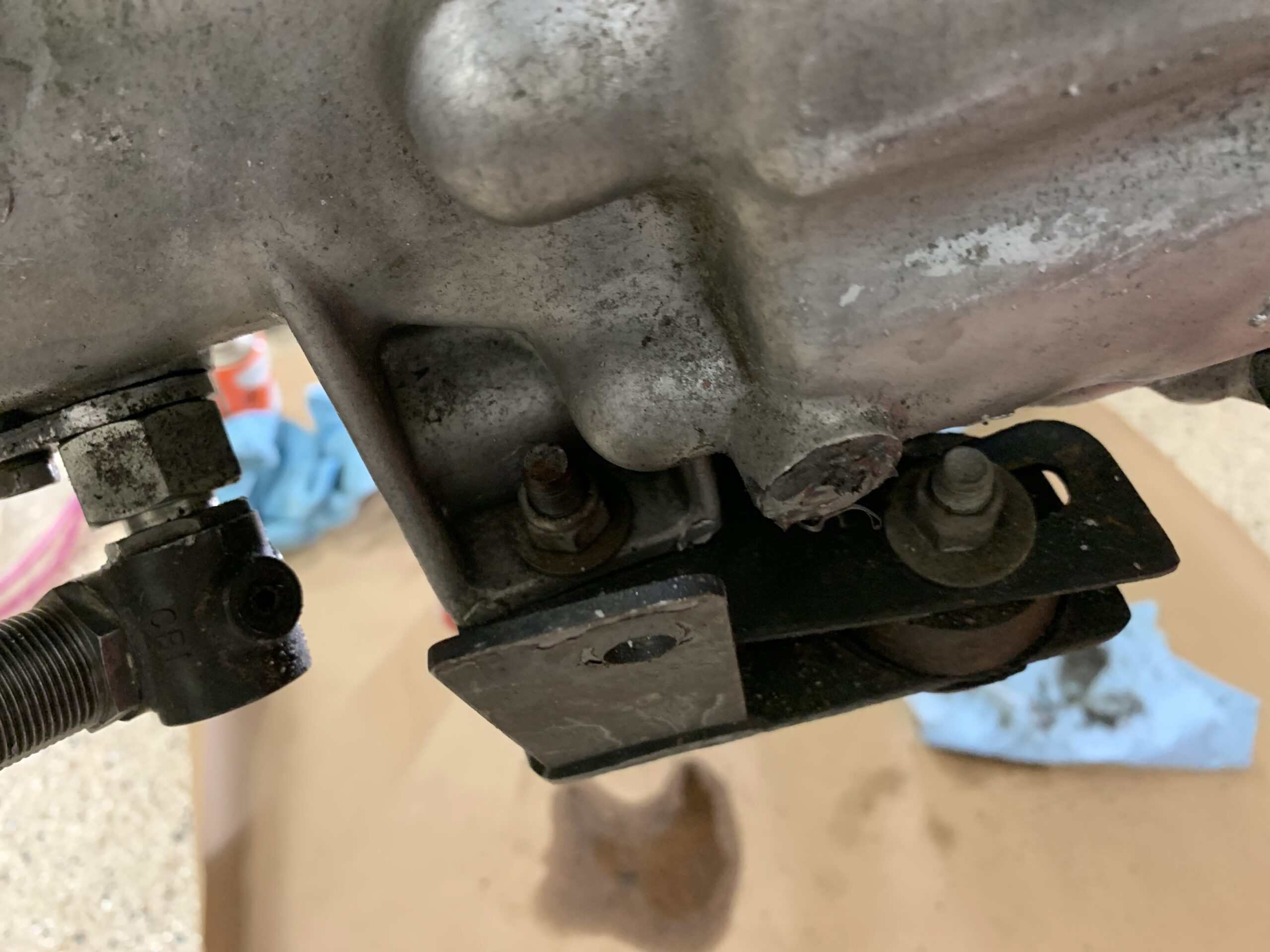
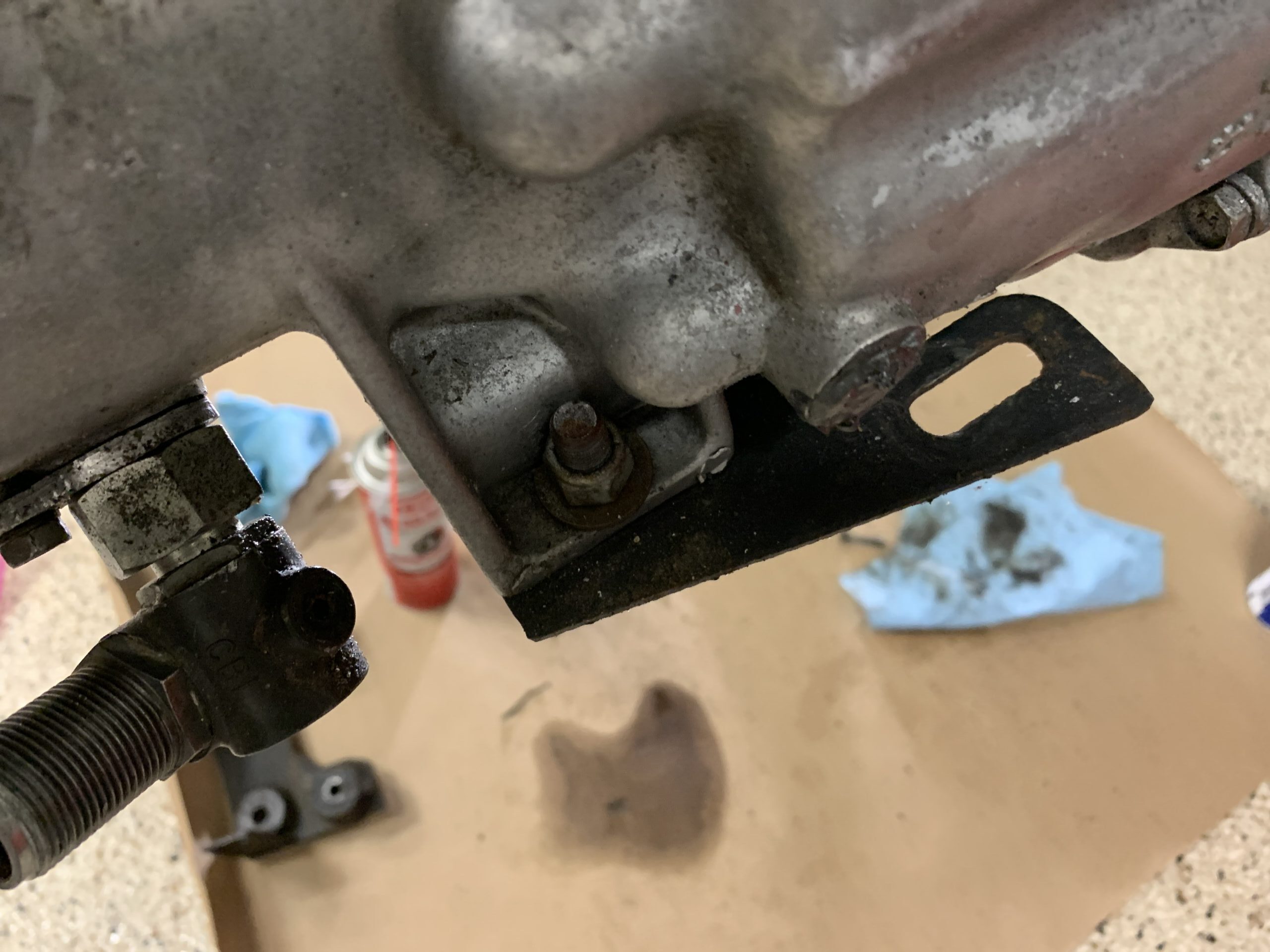
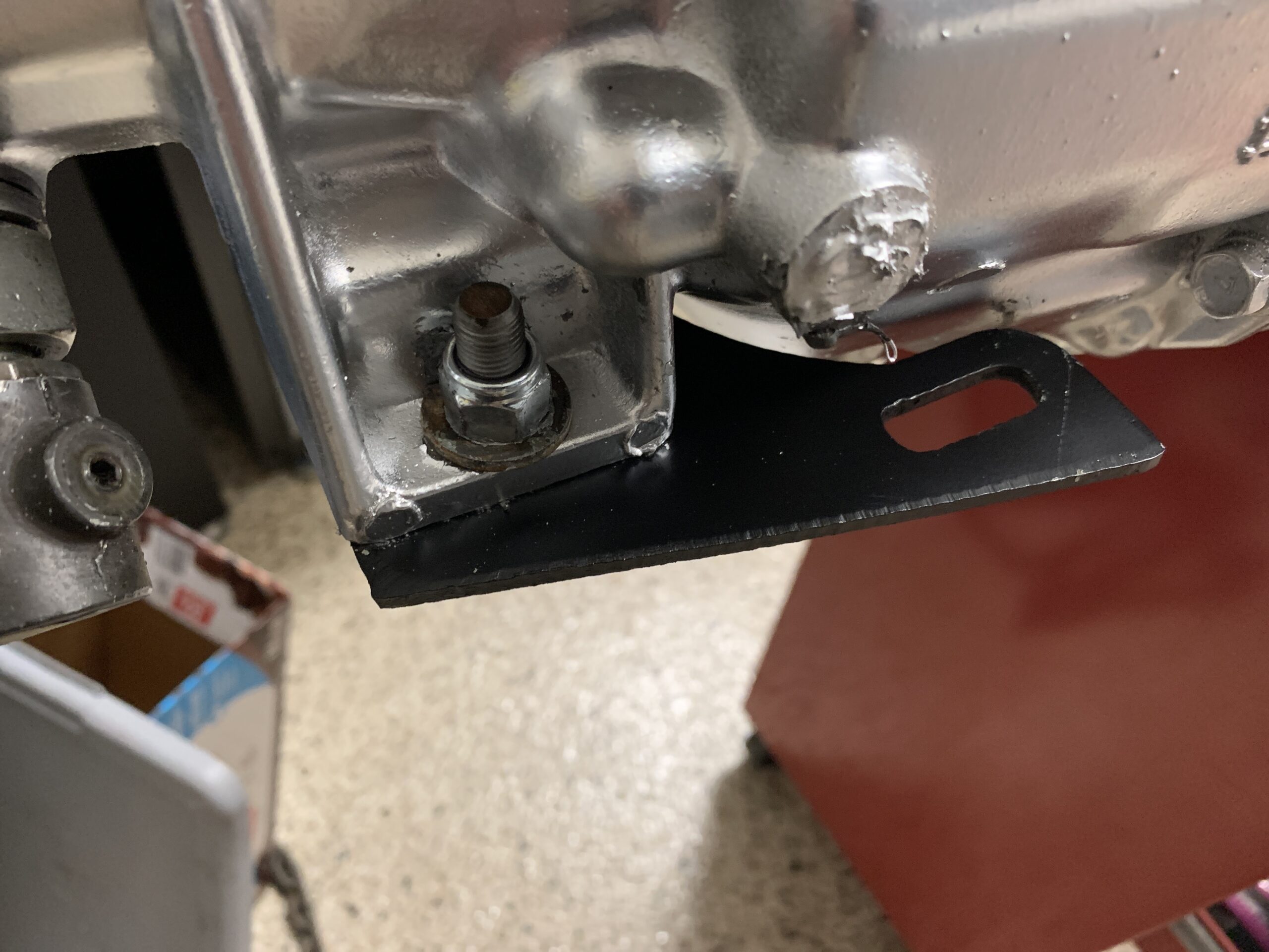
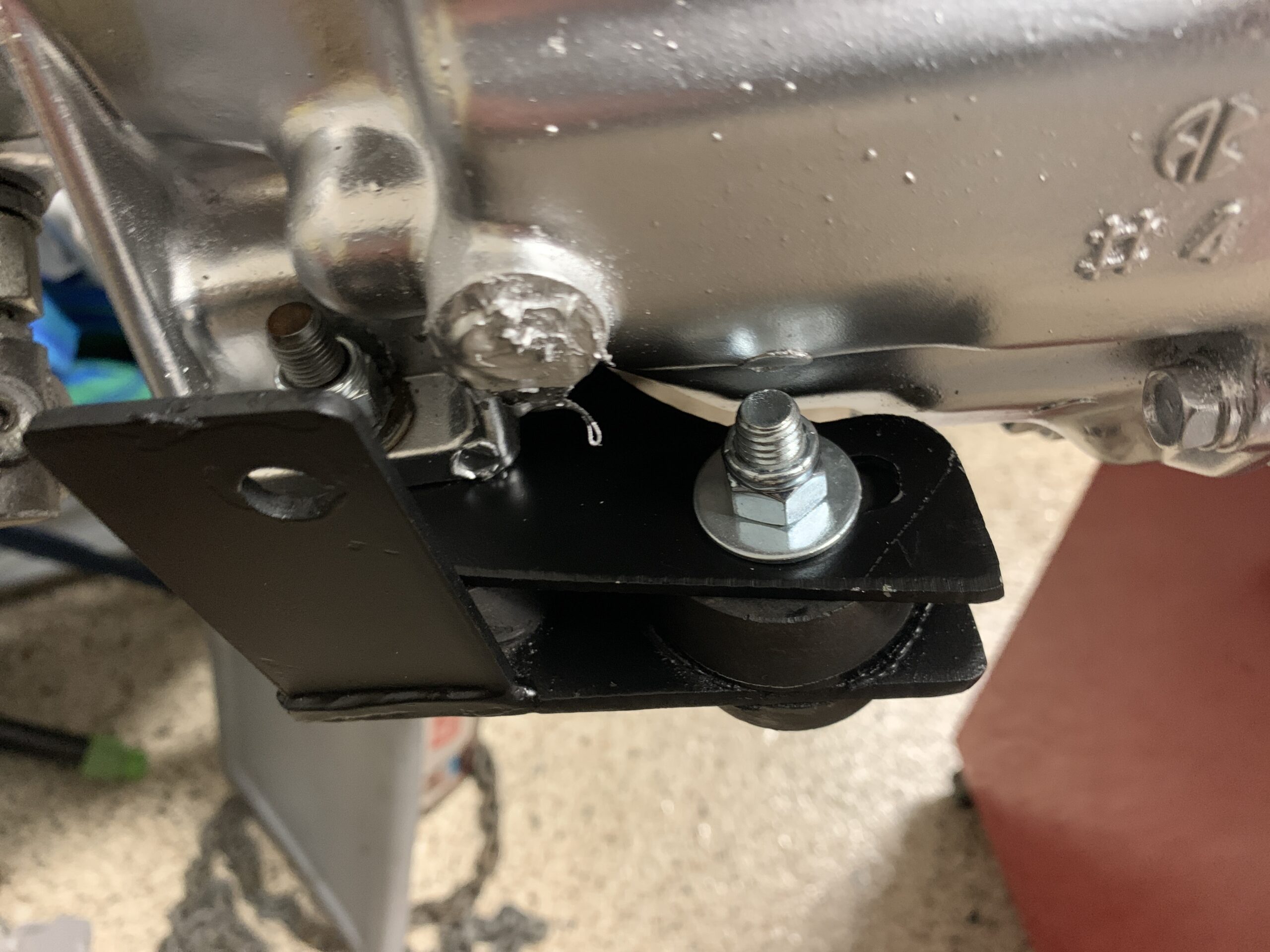
The LH and RH engine mounts cannot be confused as they are handed. The RH mount and rubber cushion was removed.
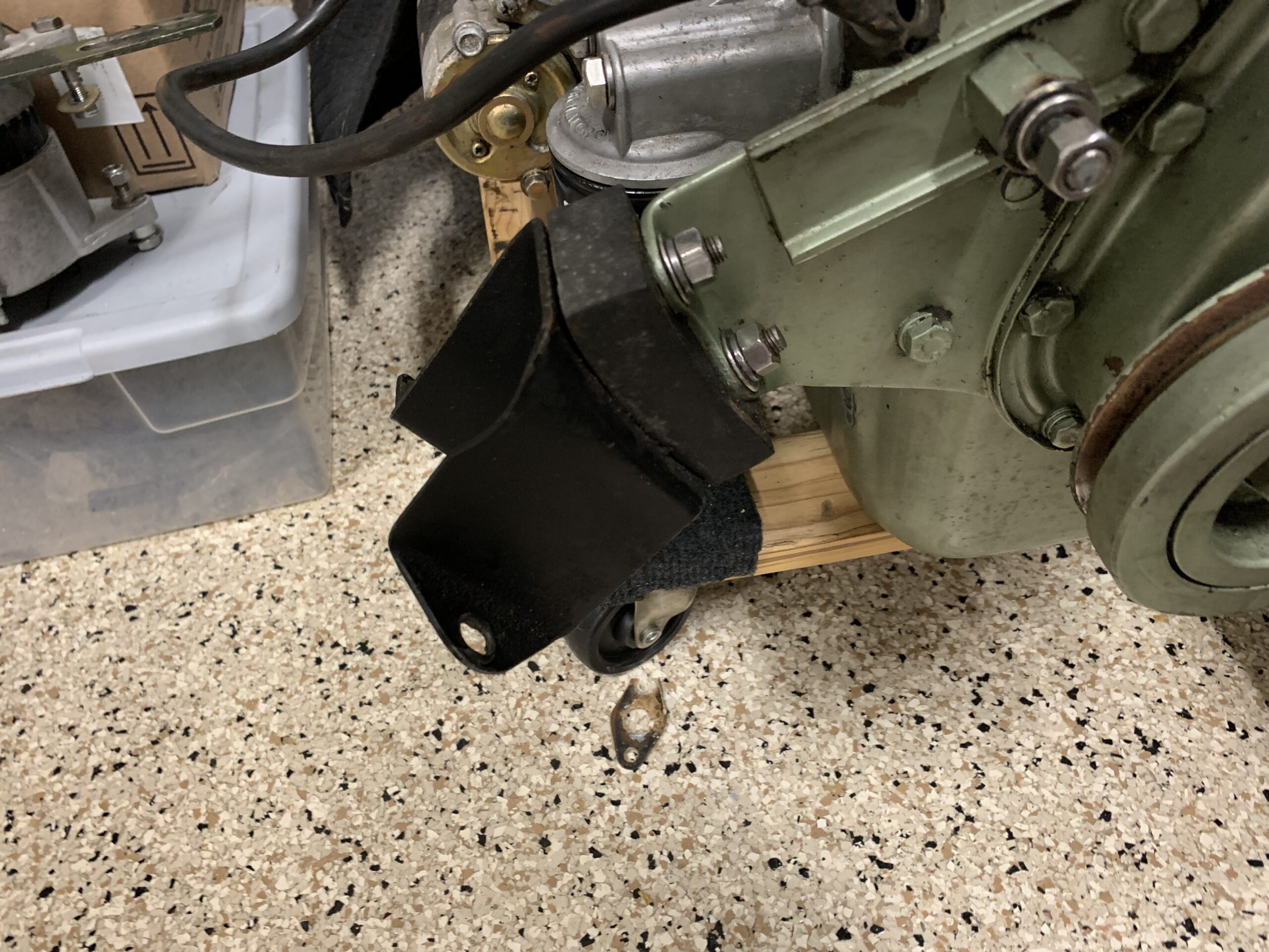
Removed RH Engine Mount
Right front motor mount cleaned and painted with POR 15 with new pads installed.
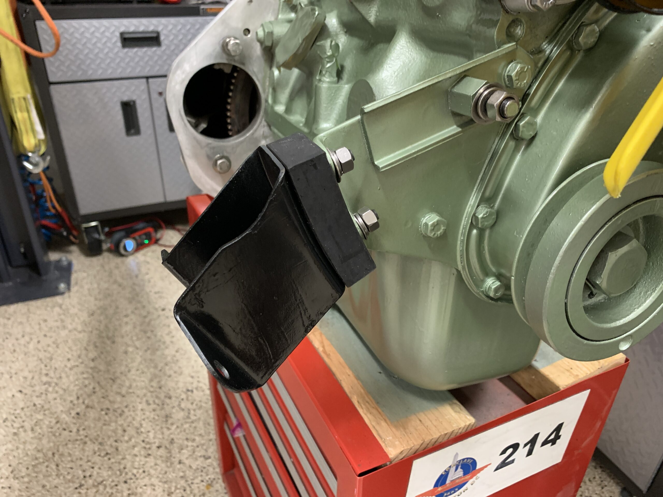
RH Motor Mount Installed
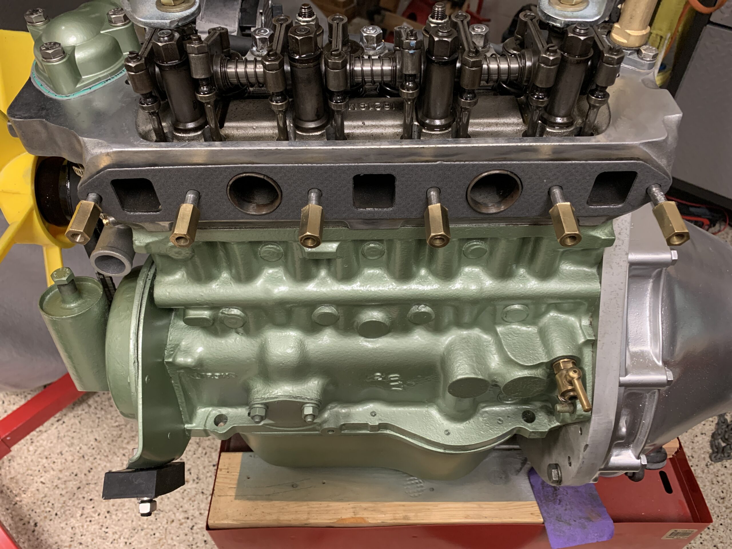
The cylinder head was not removed but it was cleaned and polished with the TW25B lubricant to help preserve the clean surfaces. A new intake/exhaust gasket was mounted to the cylinder head.
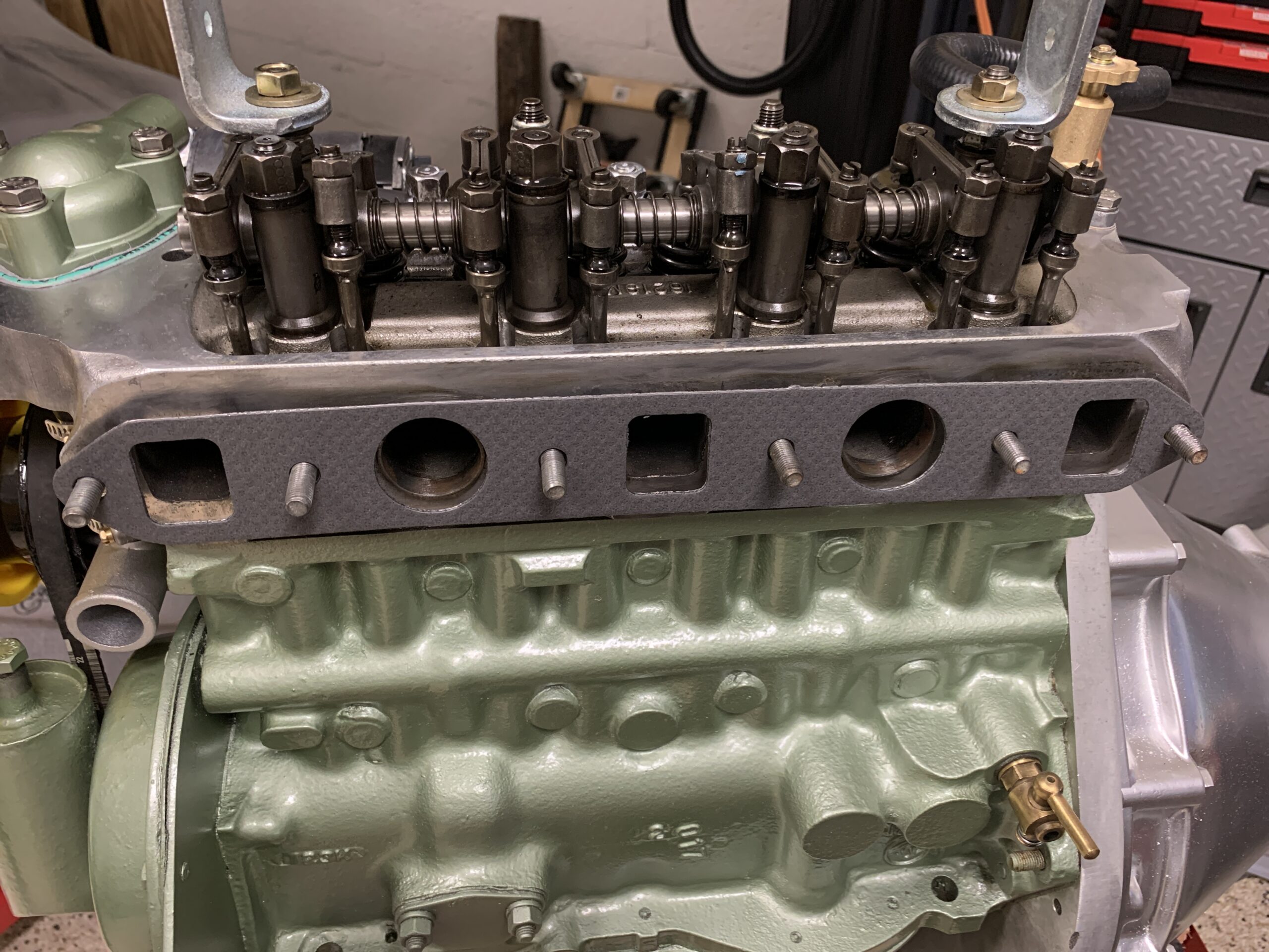
Cleaned Cylinder Head and new Gasket
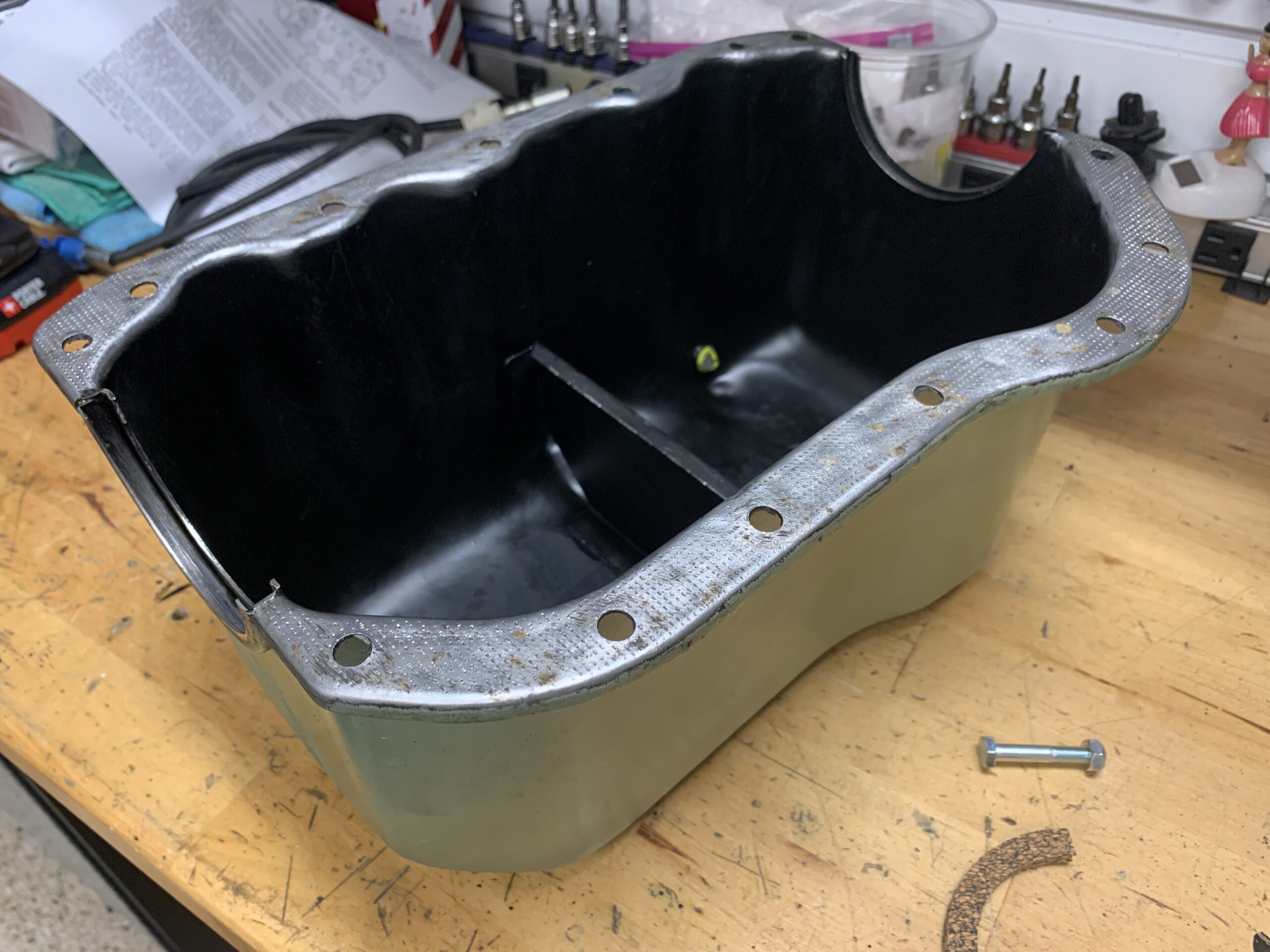
After the engine was reinstalled in the car, the oil sump was removed from the engine. It is mounted to the bottom of the block with 14 1/4”-28 X head bolts with elongated flat washers. New gaskets and seals for the pan from Mini Mania. The rear seal which was leaking pretty badly was replaced with a neoprene special seal and a cork seal will be used in the front as we could not locate a neoprene front seal. Unlike the original seals, these new seals came preformed and will hopefully seal a little better than the original straight cork that was pushed into place. The gaskets were installed using GasGacinch gasket sealer.
Old Cork Seal Removed from Oil Sump
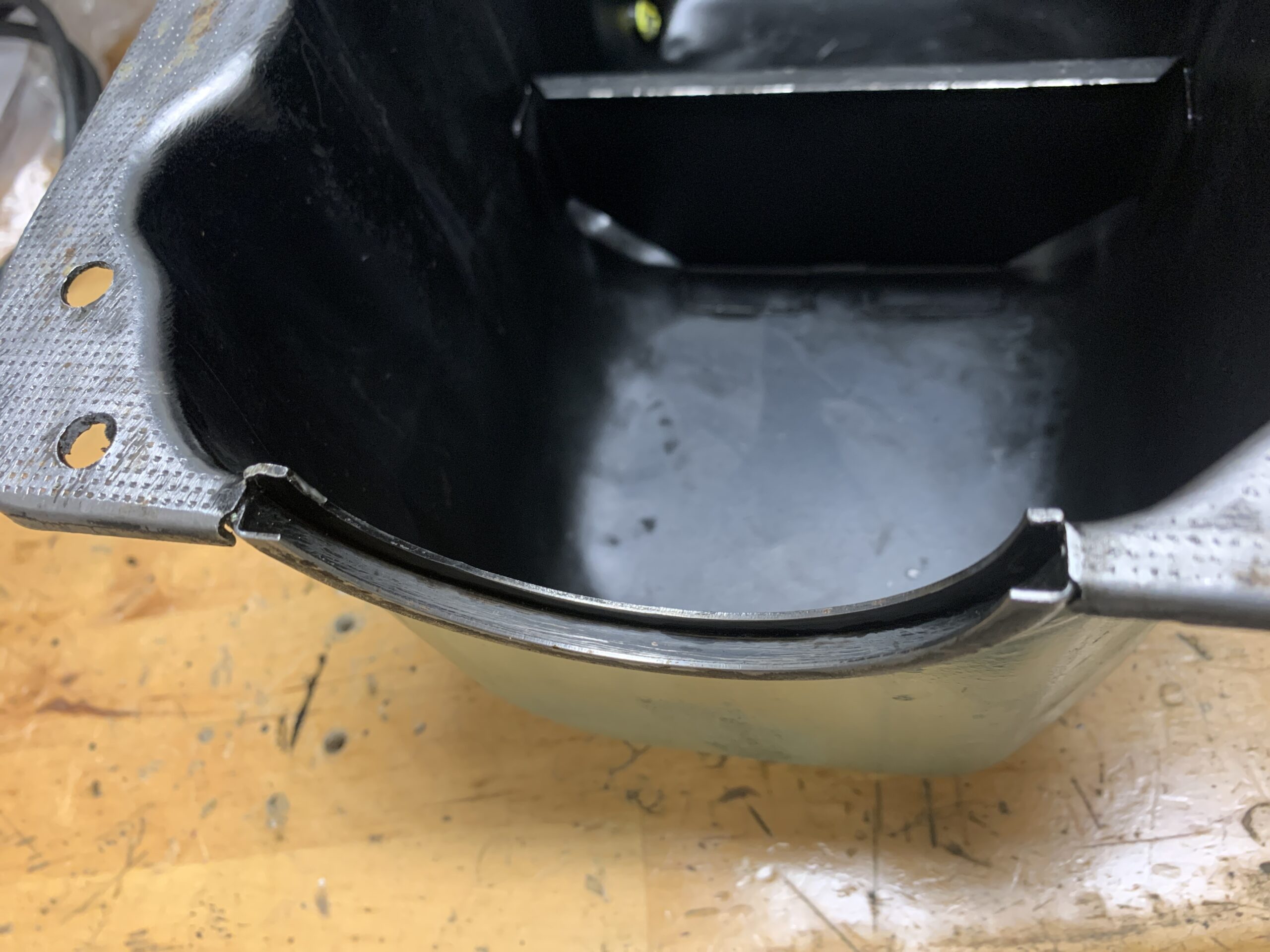
Oil Sump Channel for Seal
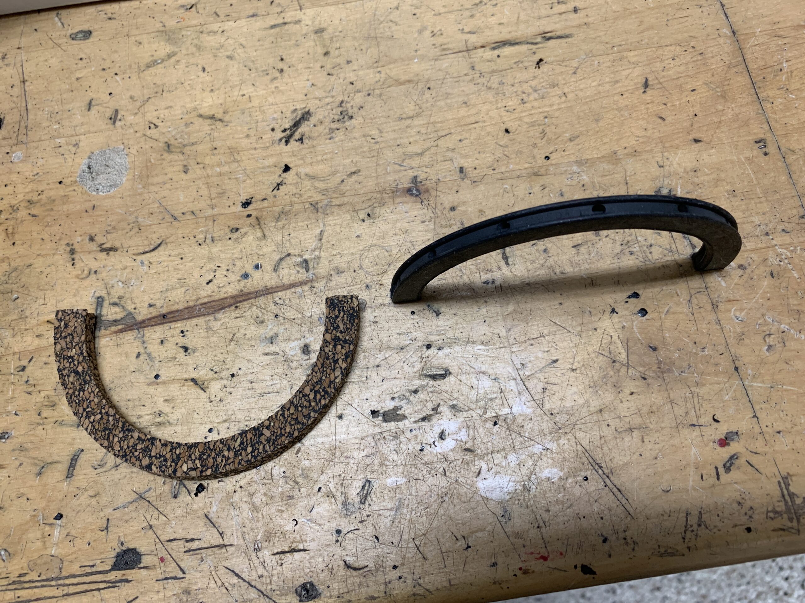
New Seals for the Oil Sump
Freshly painted Oil Sump
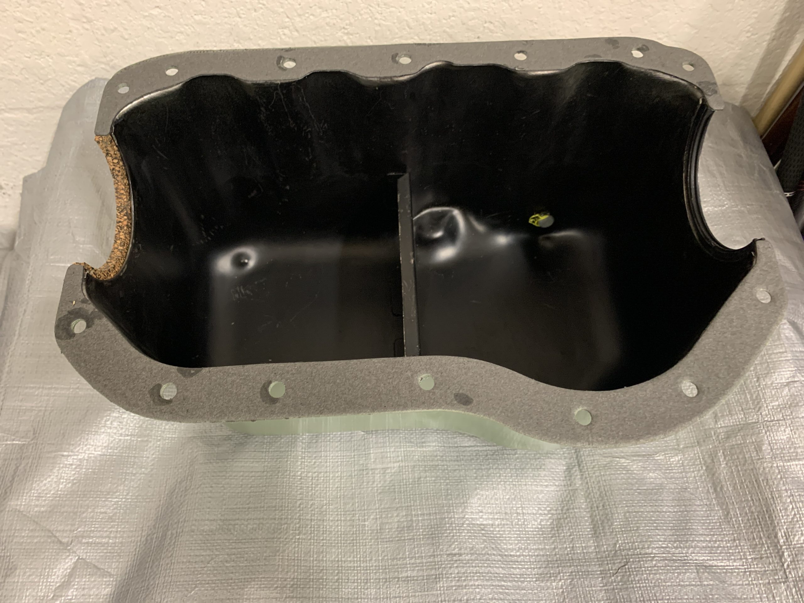
Oil pan cleaned up painted with new gaskets cork seal at the front and neoprene at the rear.
Oil Sump with Gaskets Installed
Oil Sump installed. Hylomar used on gasket and neoprene rear seal. Synthetic grease used on front cork seal. Black RtV used in the corners.
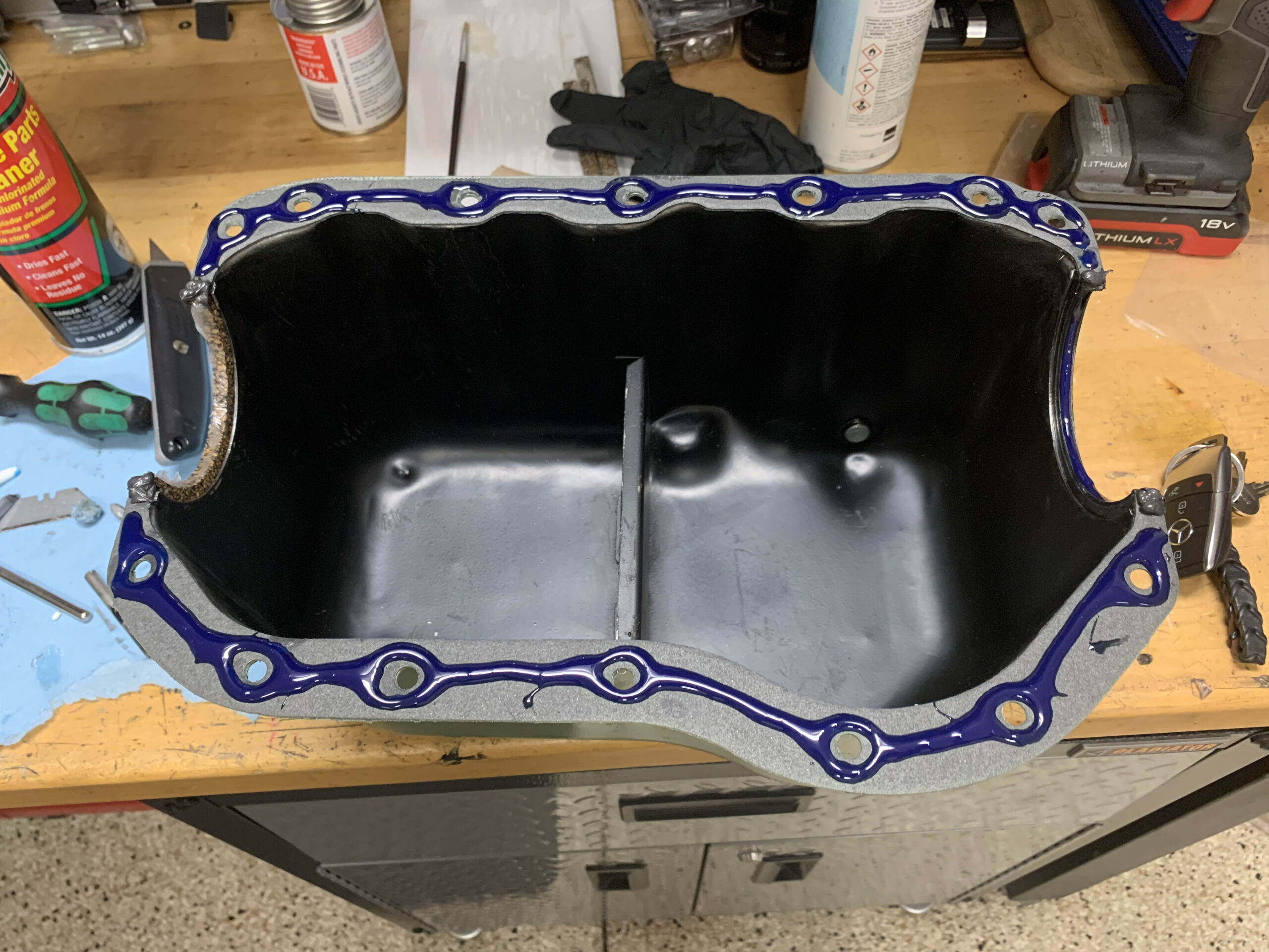
Oil Sump with Hylomar Sealant
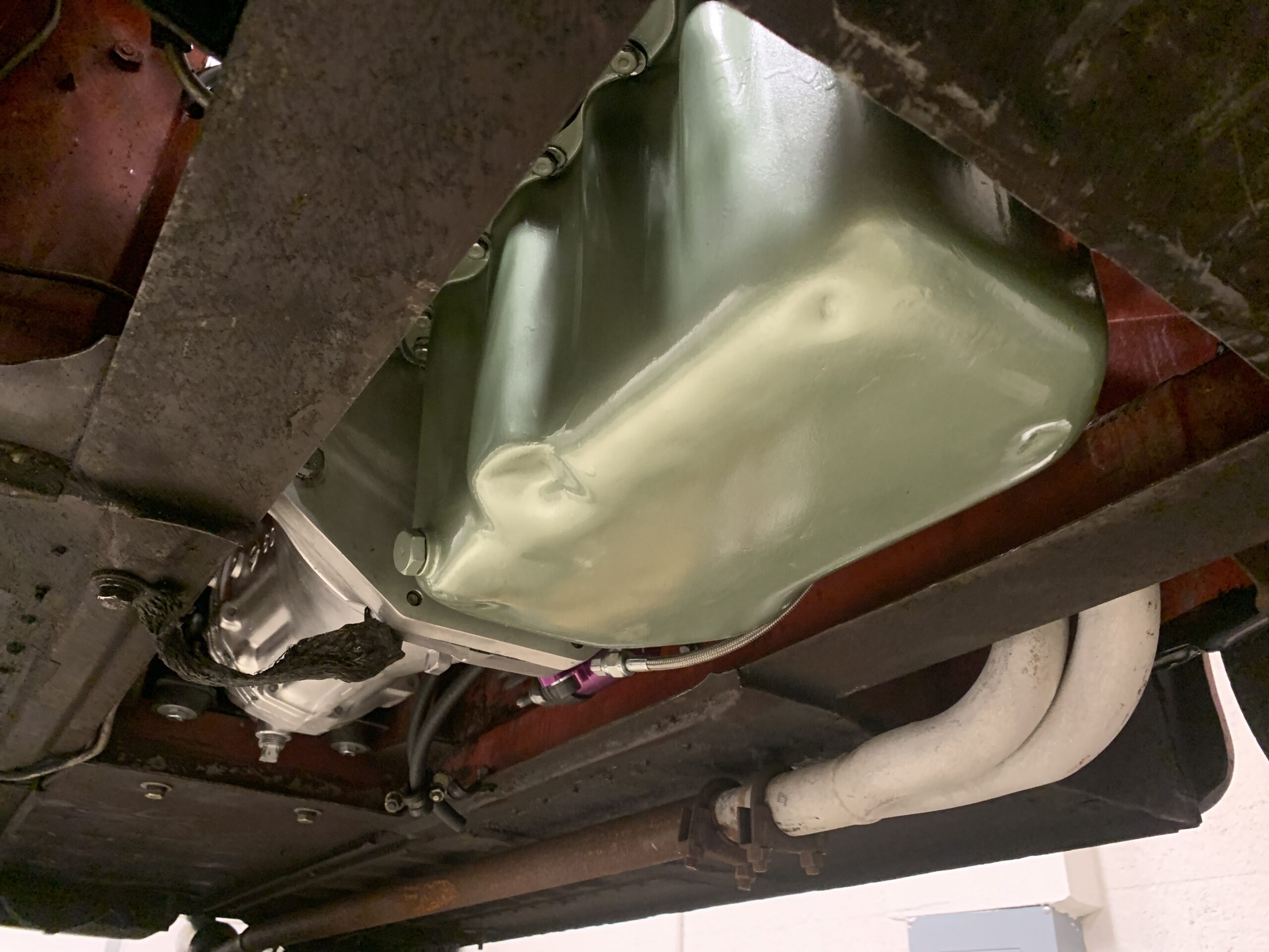
Oil Sump Installed
Fuel
The K&N Air Cleaners were still in great shape. They were removed to clean and polish. The filters were washed and re-oiled before installation on the engine.
K&N Air Cleaner back plate
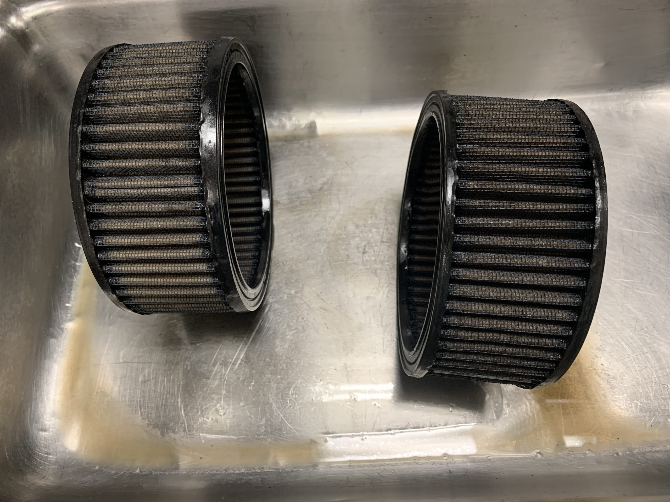
K&N Filter elements cleaned
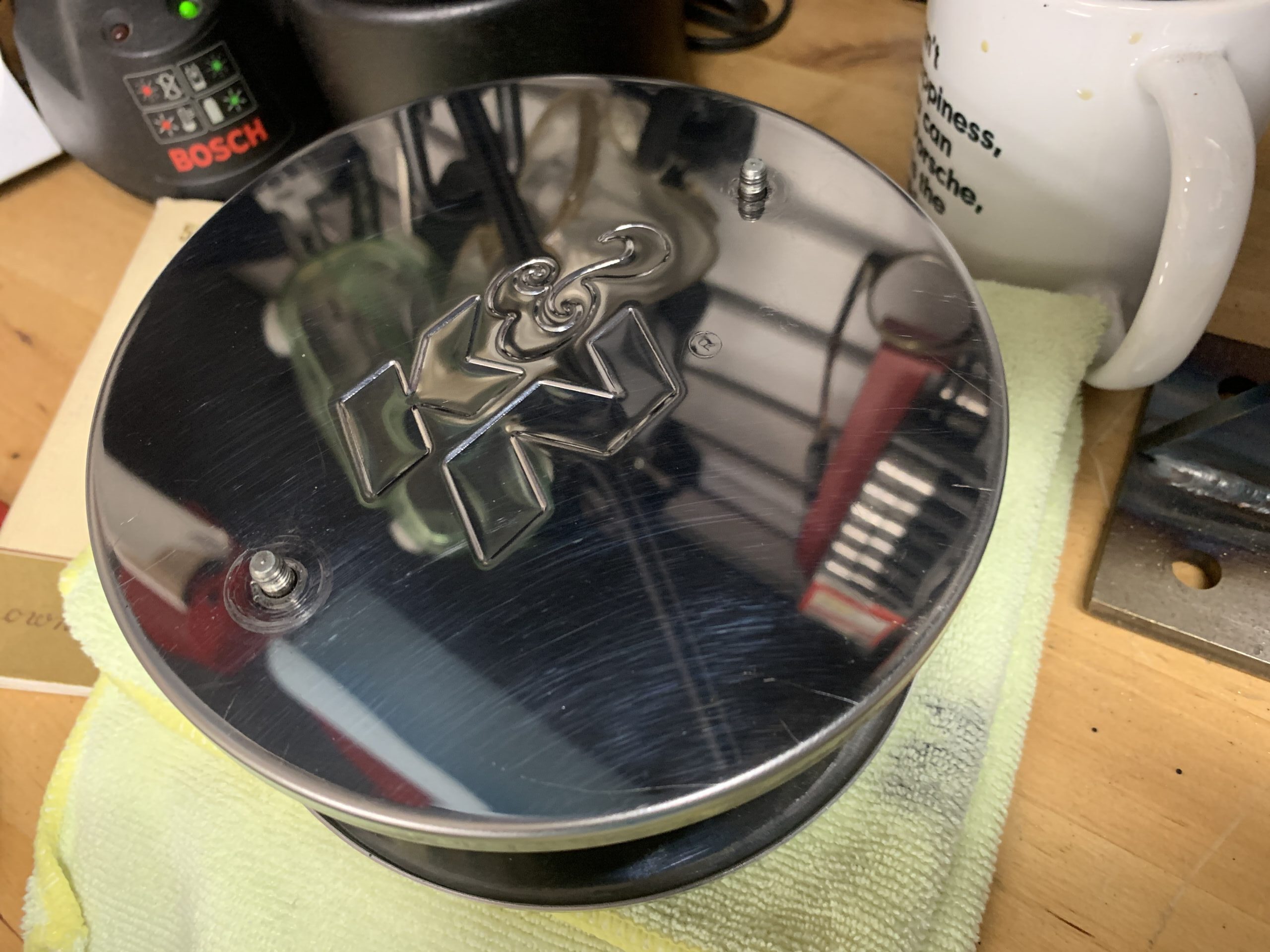
K&N Air Filter Faceplates Cleaned and Polished
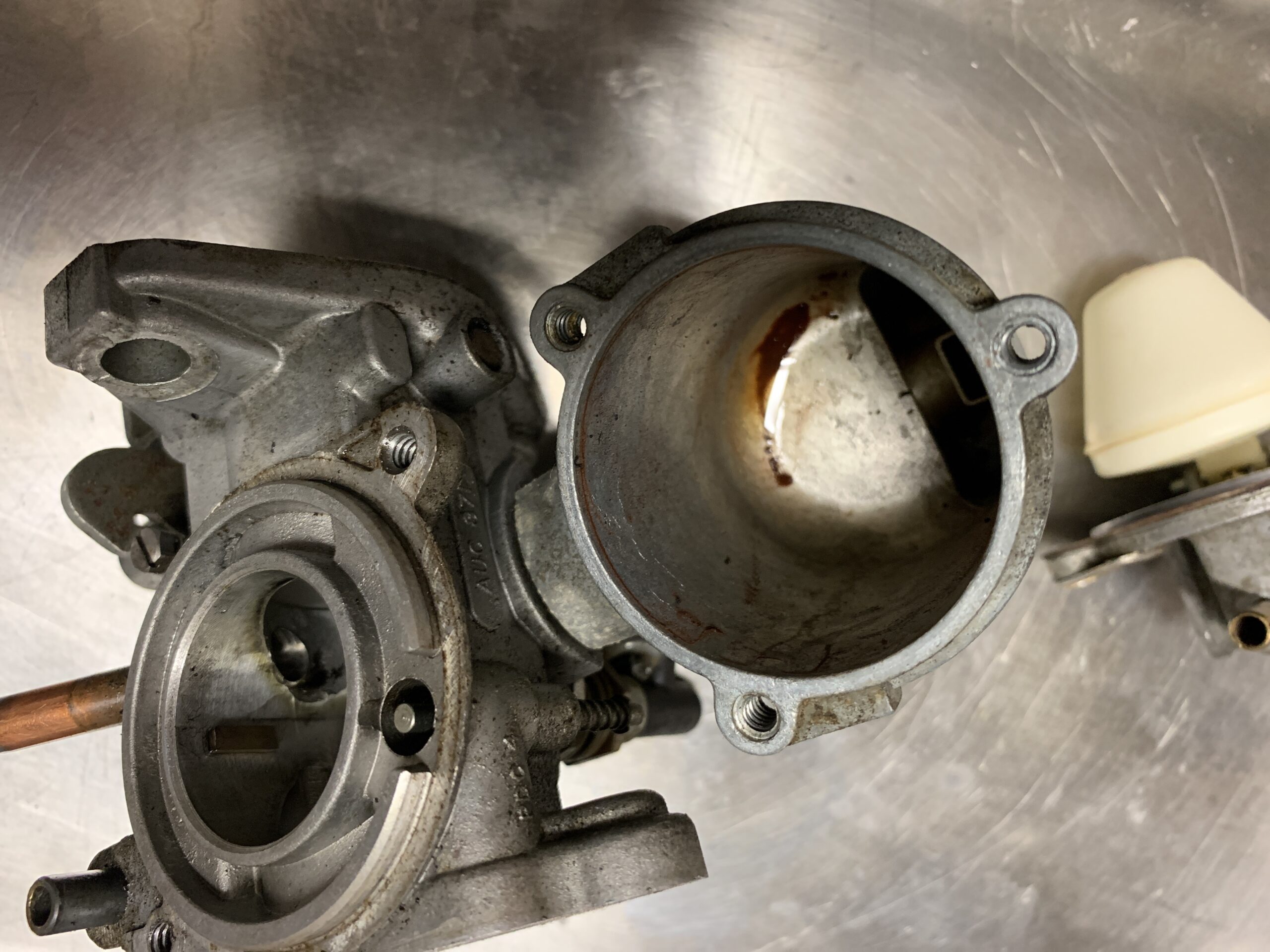
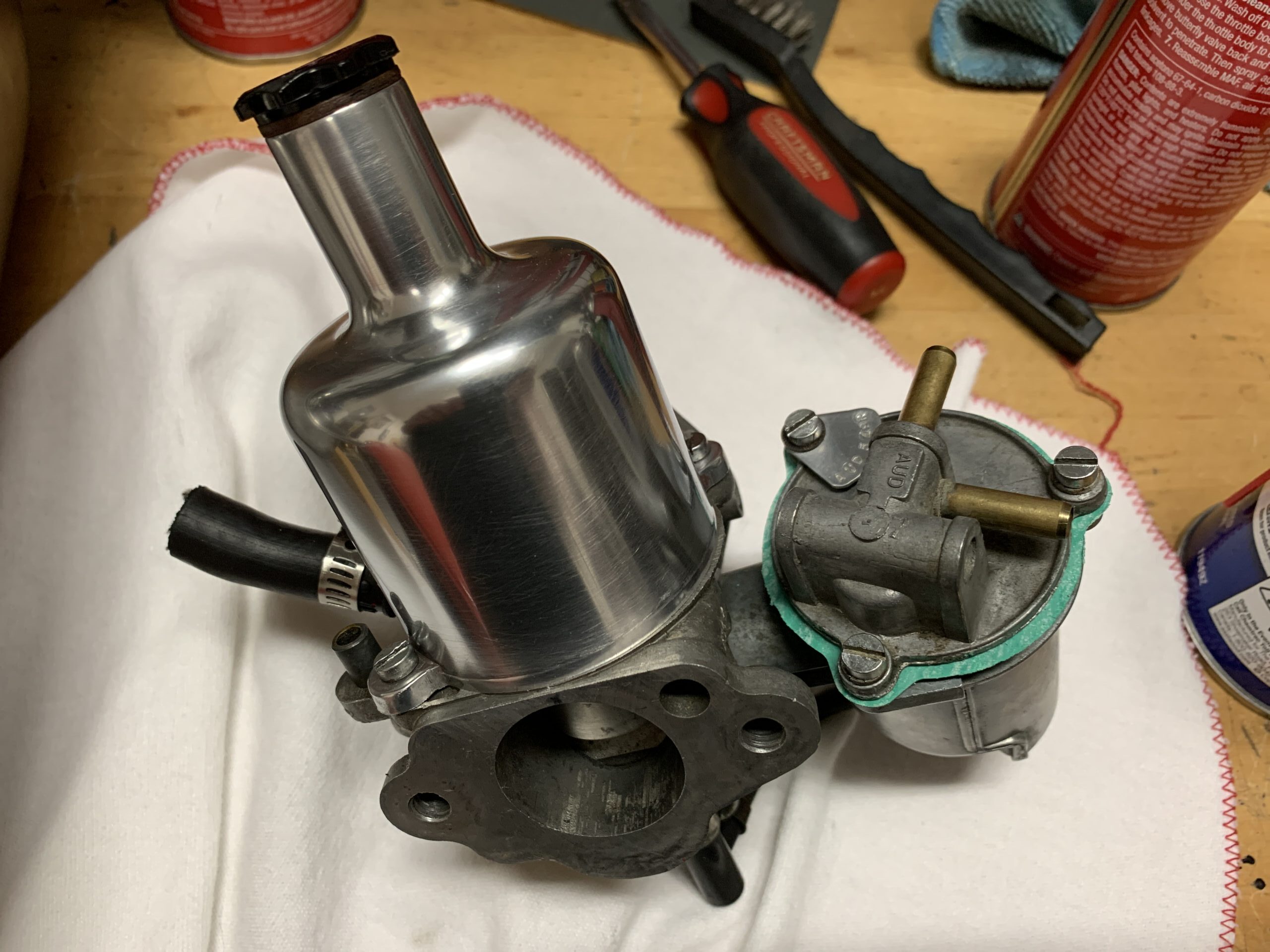
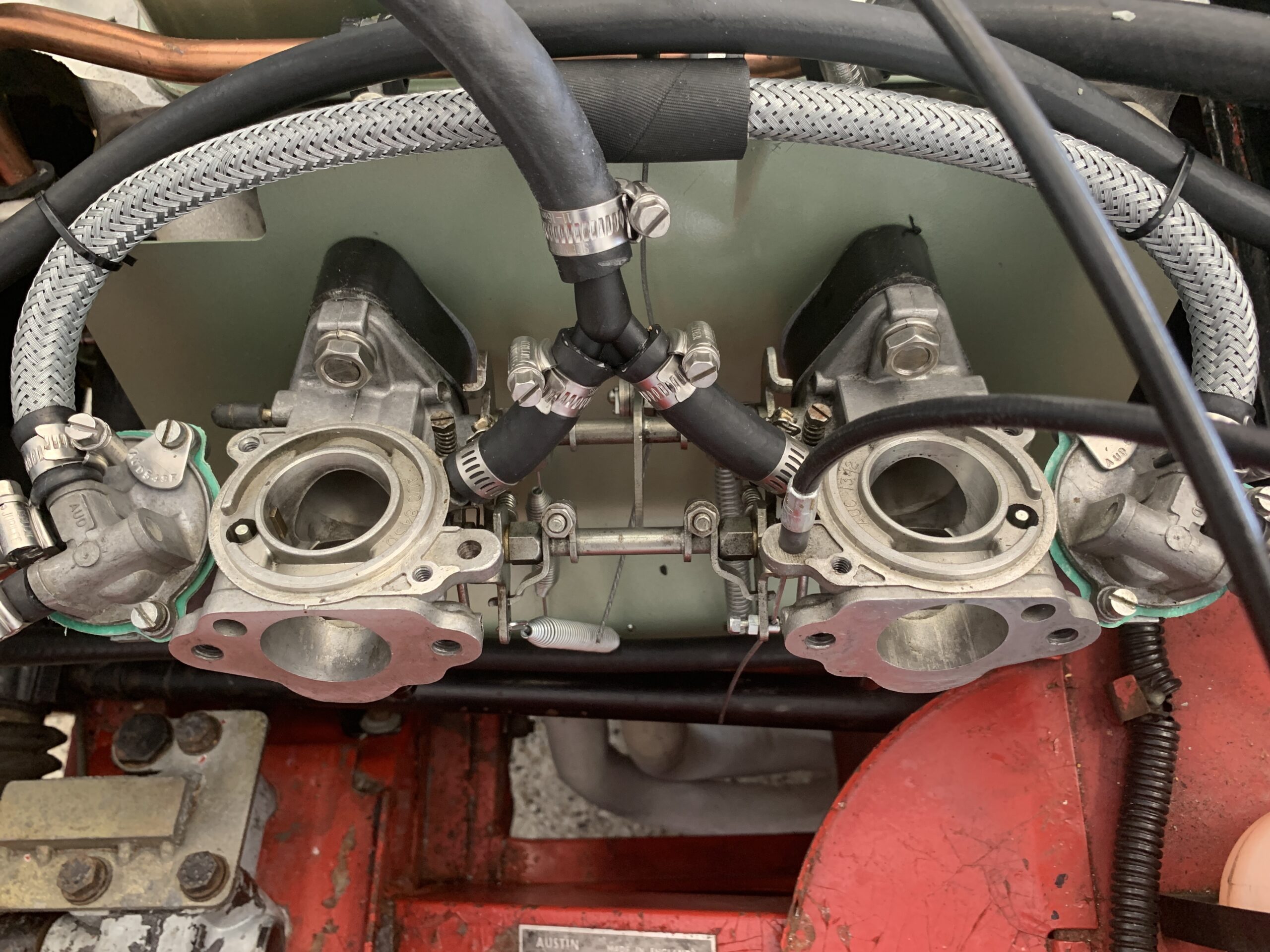
The twin HS2 SU carbs were removed from the engine for cleaning. They use 1/4″ fuel delivery hoses.
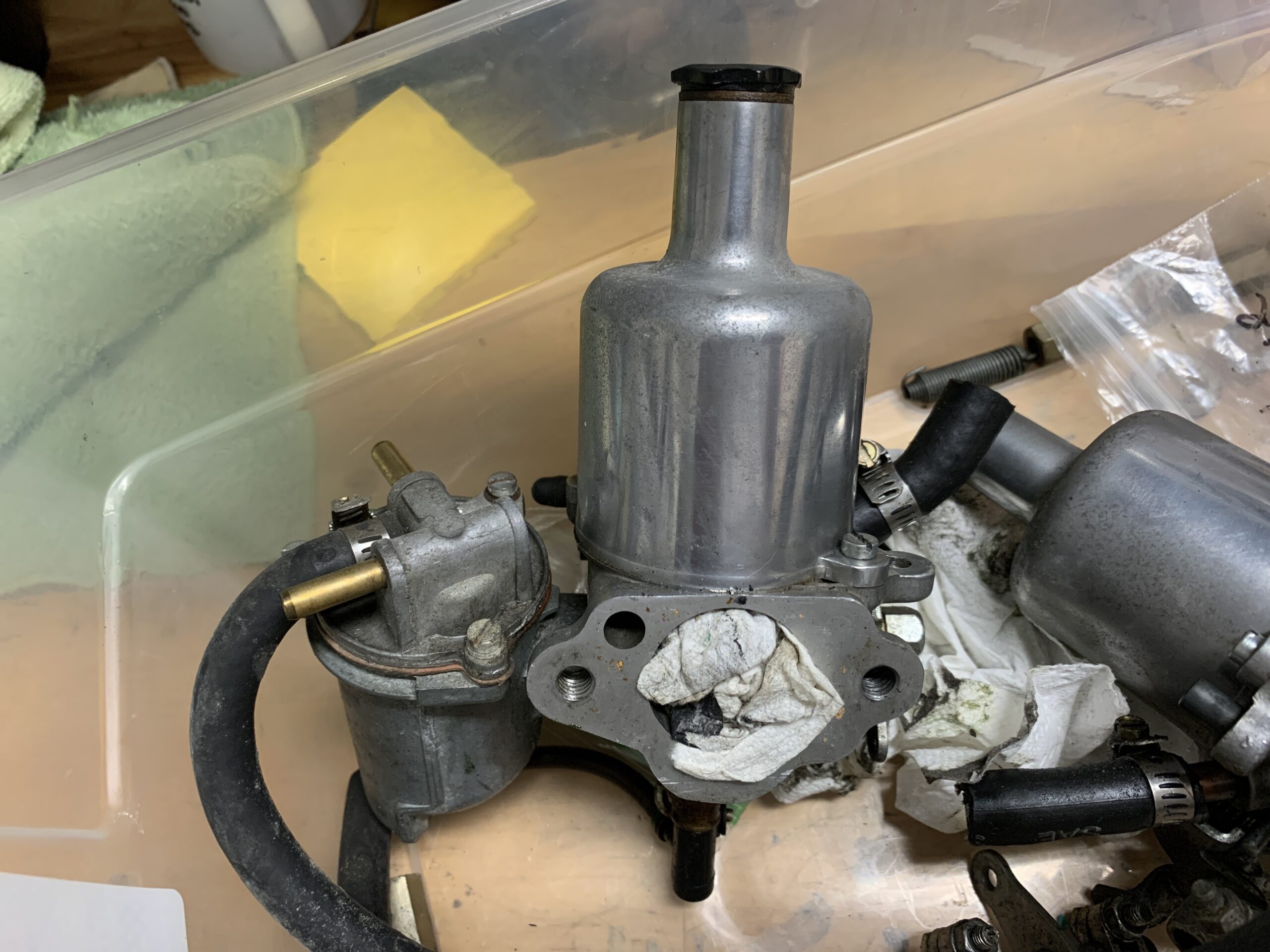
Front HS2 Carb
The front float bowl is number AUC 1310. The car body is AUC 82. The rear carb is AUC 871 and the float bowl is AUC 1310.
Rear HS2 Carb
The jet for the rear carb was down .77″.

Rear Carb 2
Hose for Y Fitting to Carb
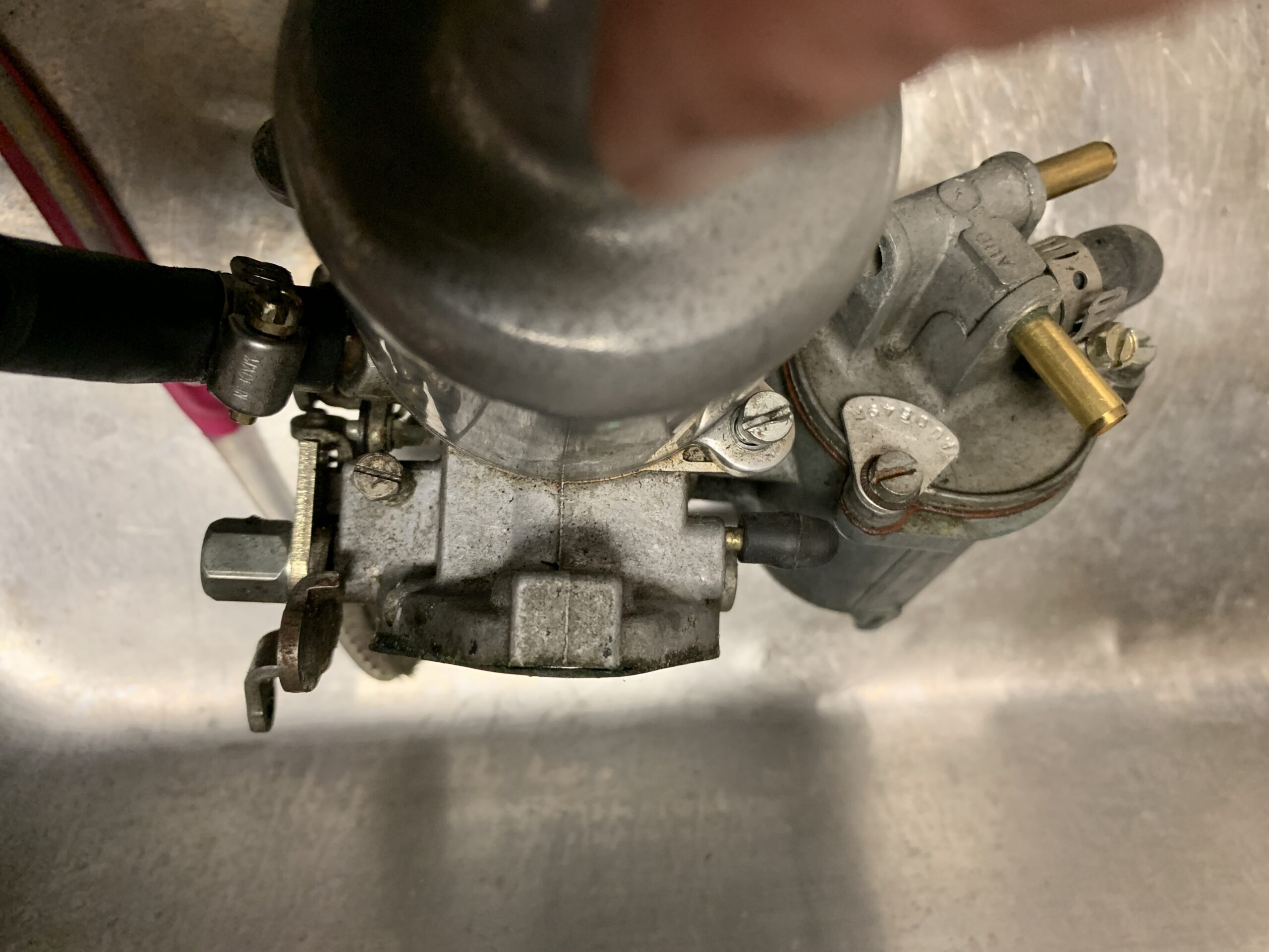
The rear carb float bowl was opened by removing the three cheesehead screws.
Rear Carb Float Bowl
There was some residue in the float bowl which was cleaned and a new lid gasket was installed. The lever mechanism for the float was working just fine and the float seemed to be in good shape.
Rear Float Bowl Residue
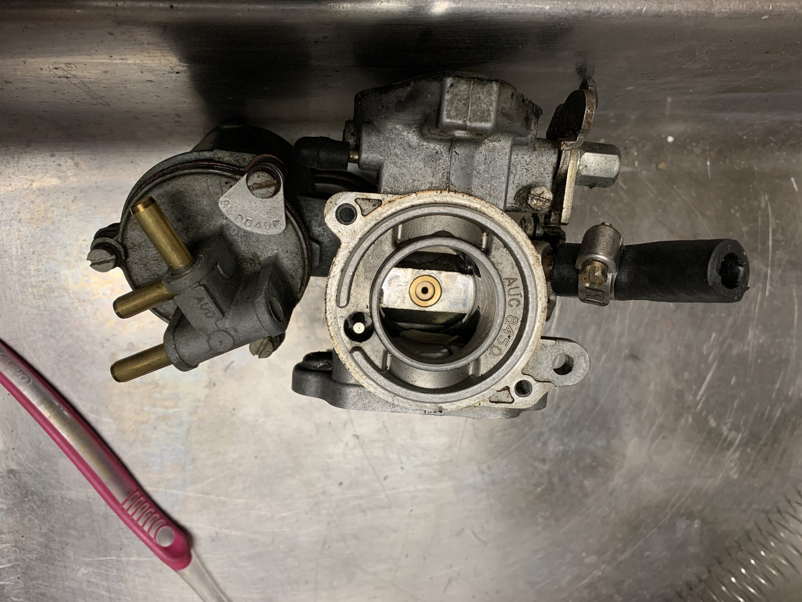
The dashpot, or vacuum chamber, was polished using various grits of sandpaper 180 sandpaper dry, 320 dry, 400 wet, 800 wet,1500 wet, 2000 wet, griots garage metal polish.
Rear Carb Cleaned and polished with new float bowl gasket
Next was the front carb.
Front Carb Ready for Cleaning
The front carb jet was down .69″
Front Carb Jet

Front Carb Disassembly
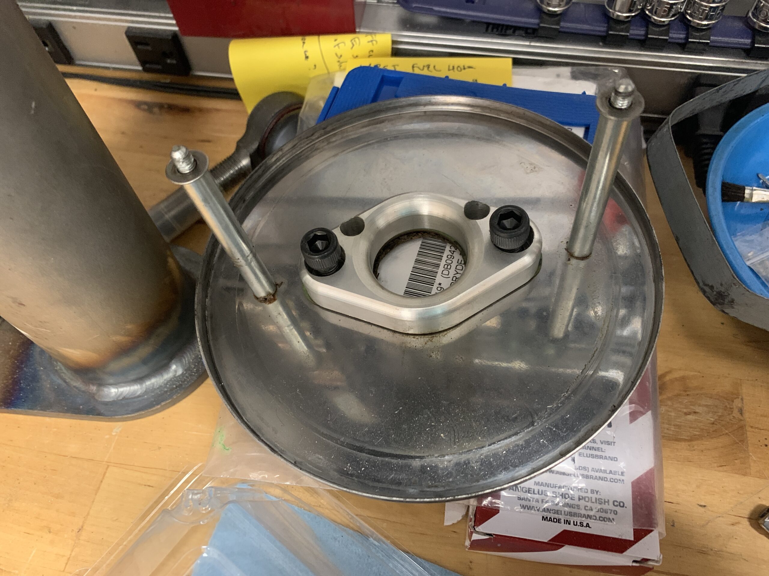
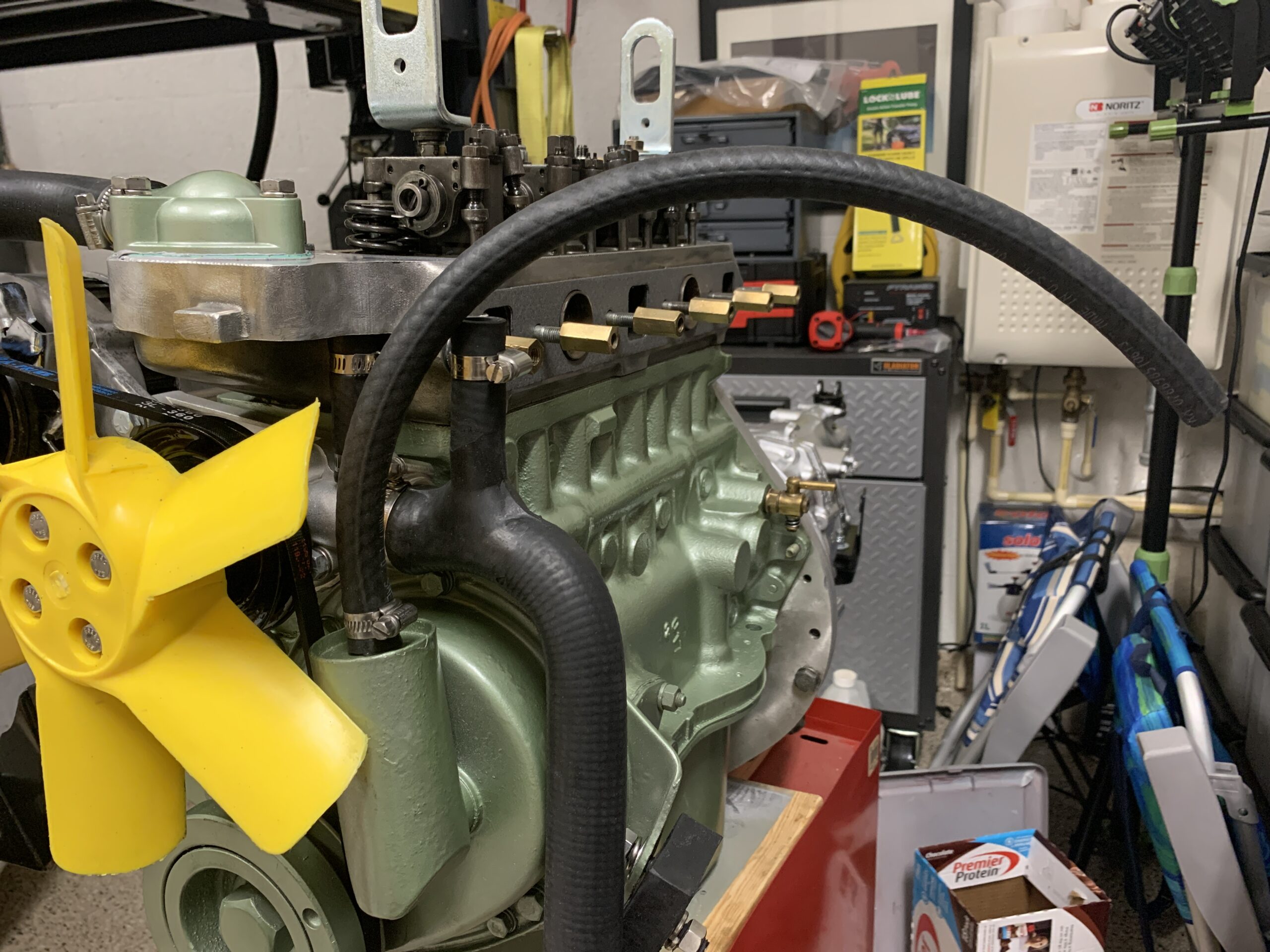
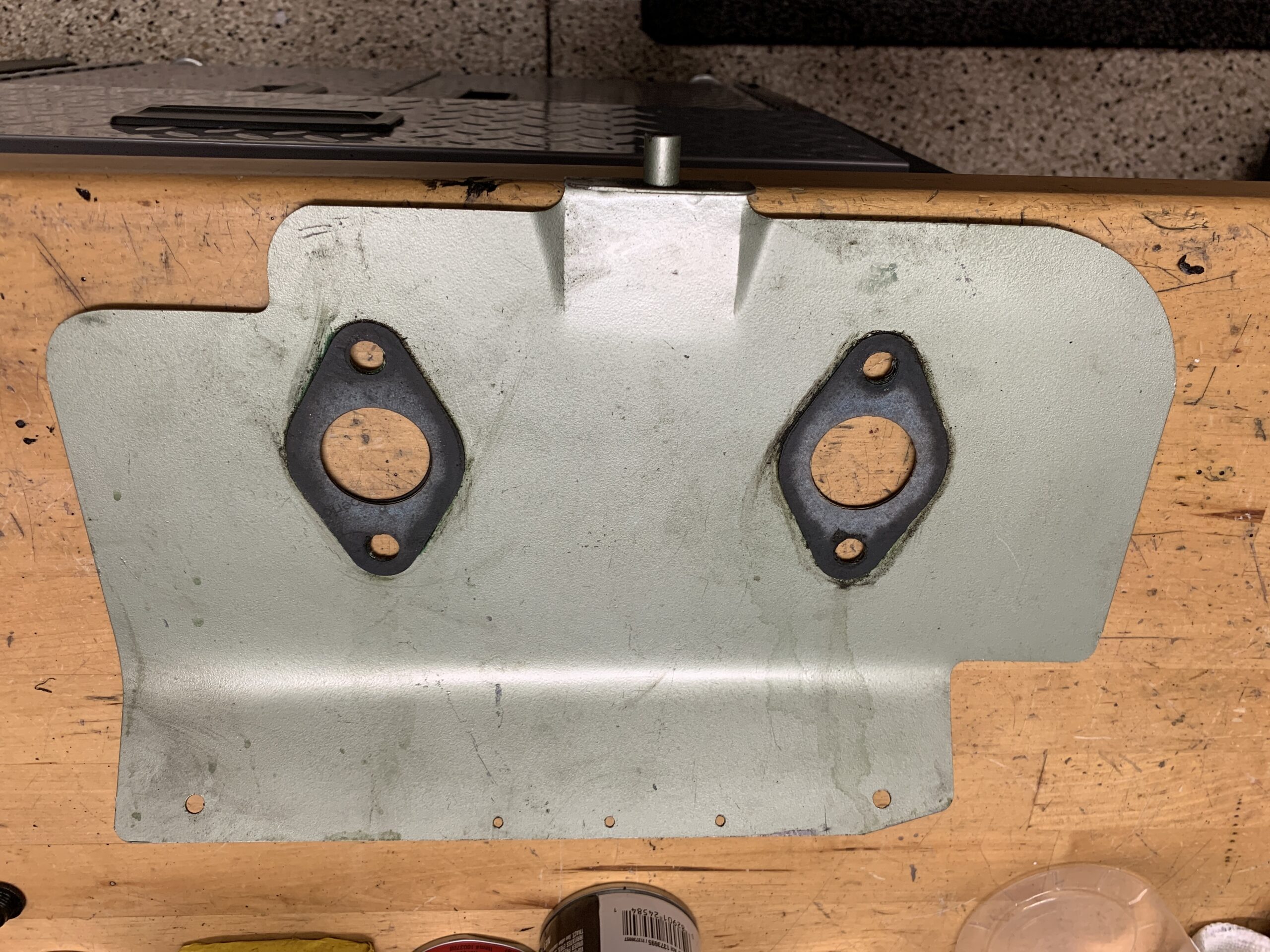
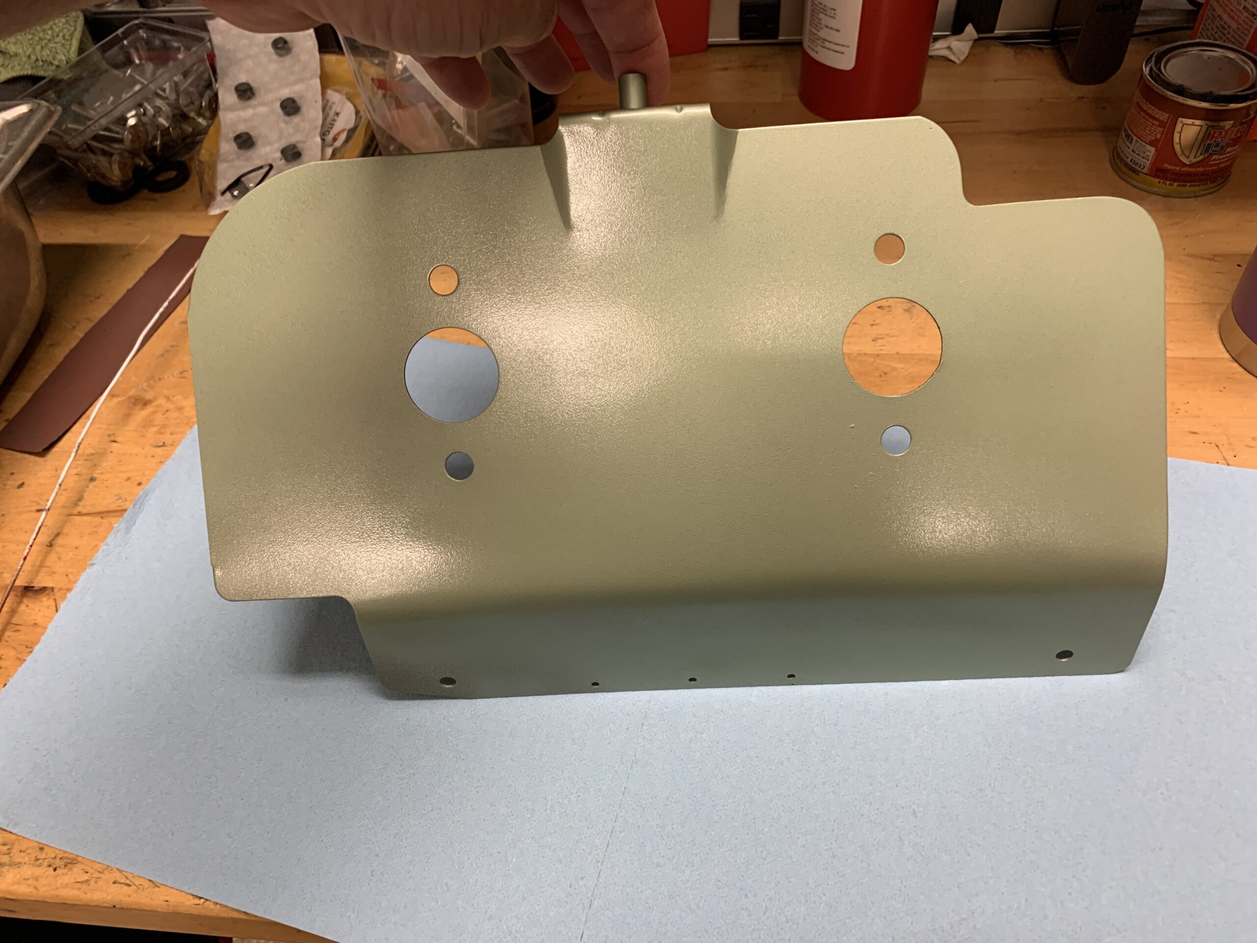
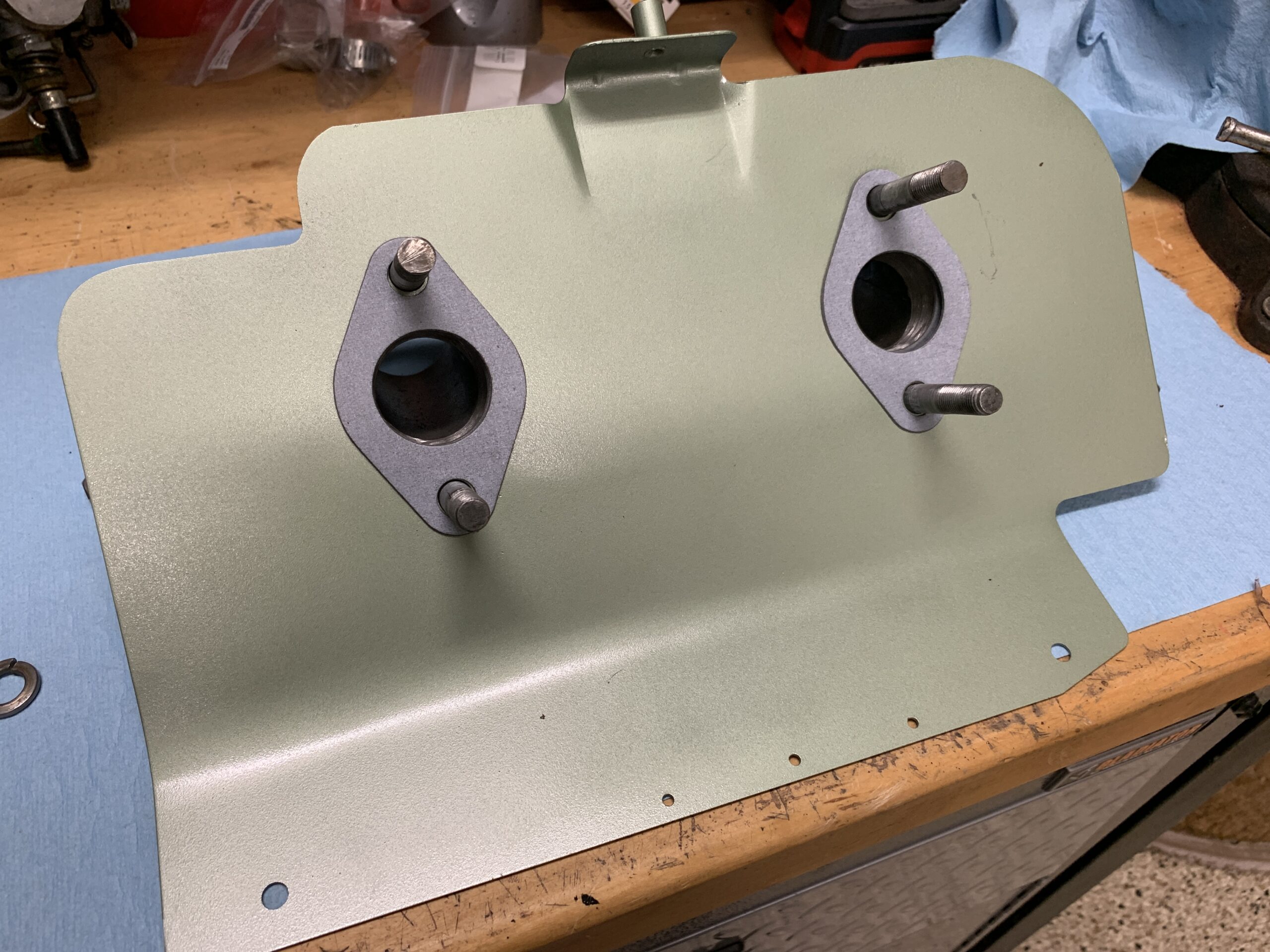
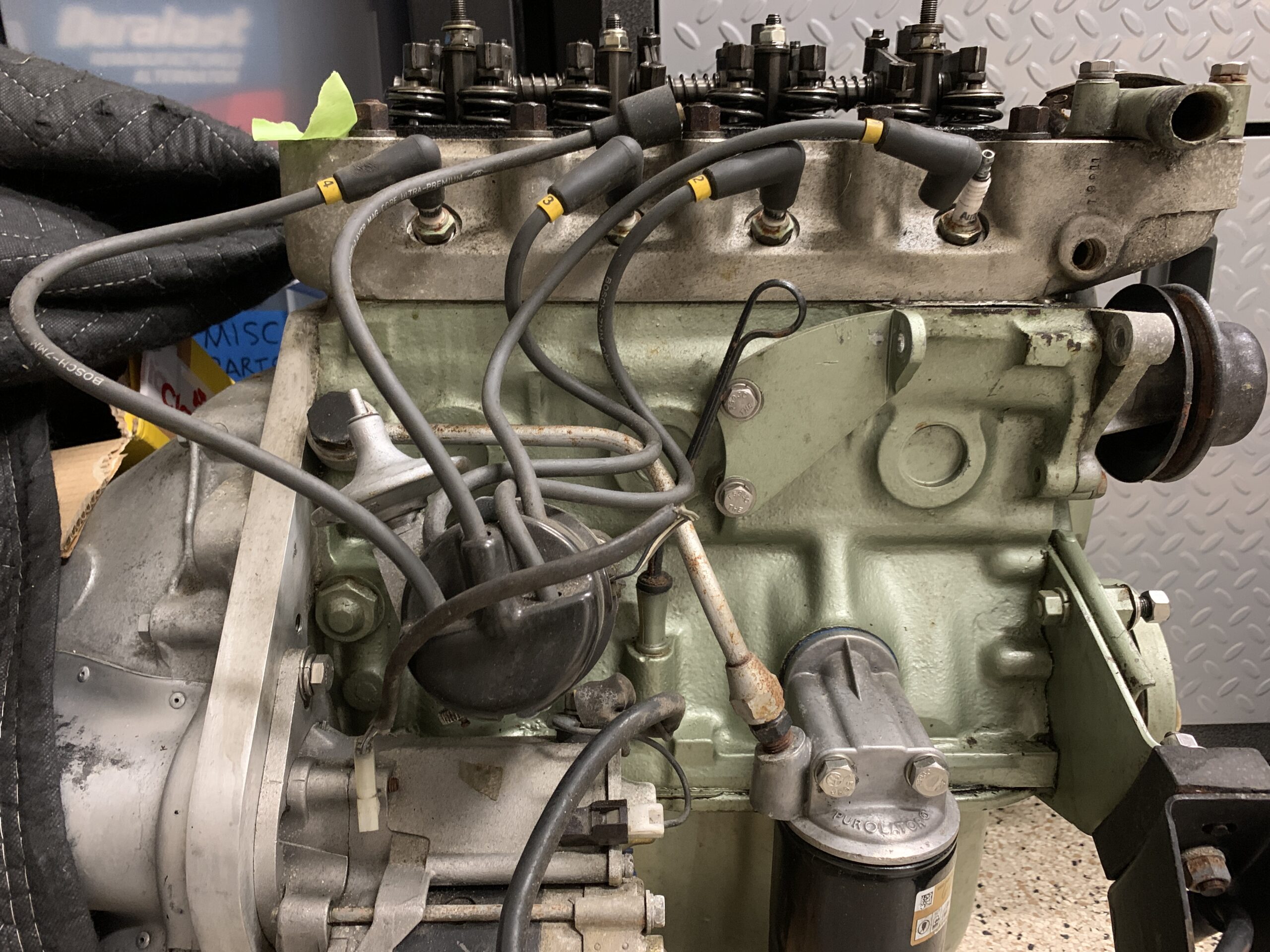
After cleaning up the carbs, attention was turned to the intake manifold and copper hot water pipe for the heater.
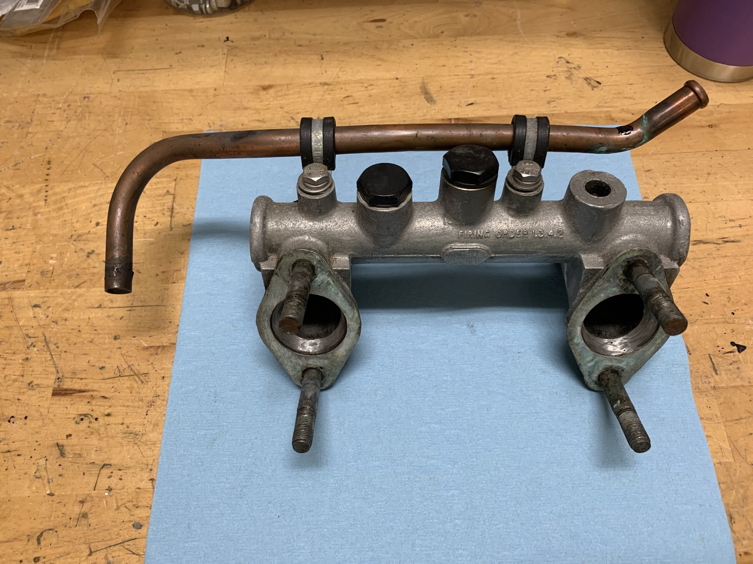
Intake Manifold and Heater Pipe Removed for Cleaning
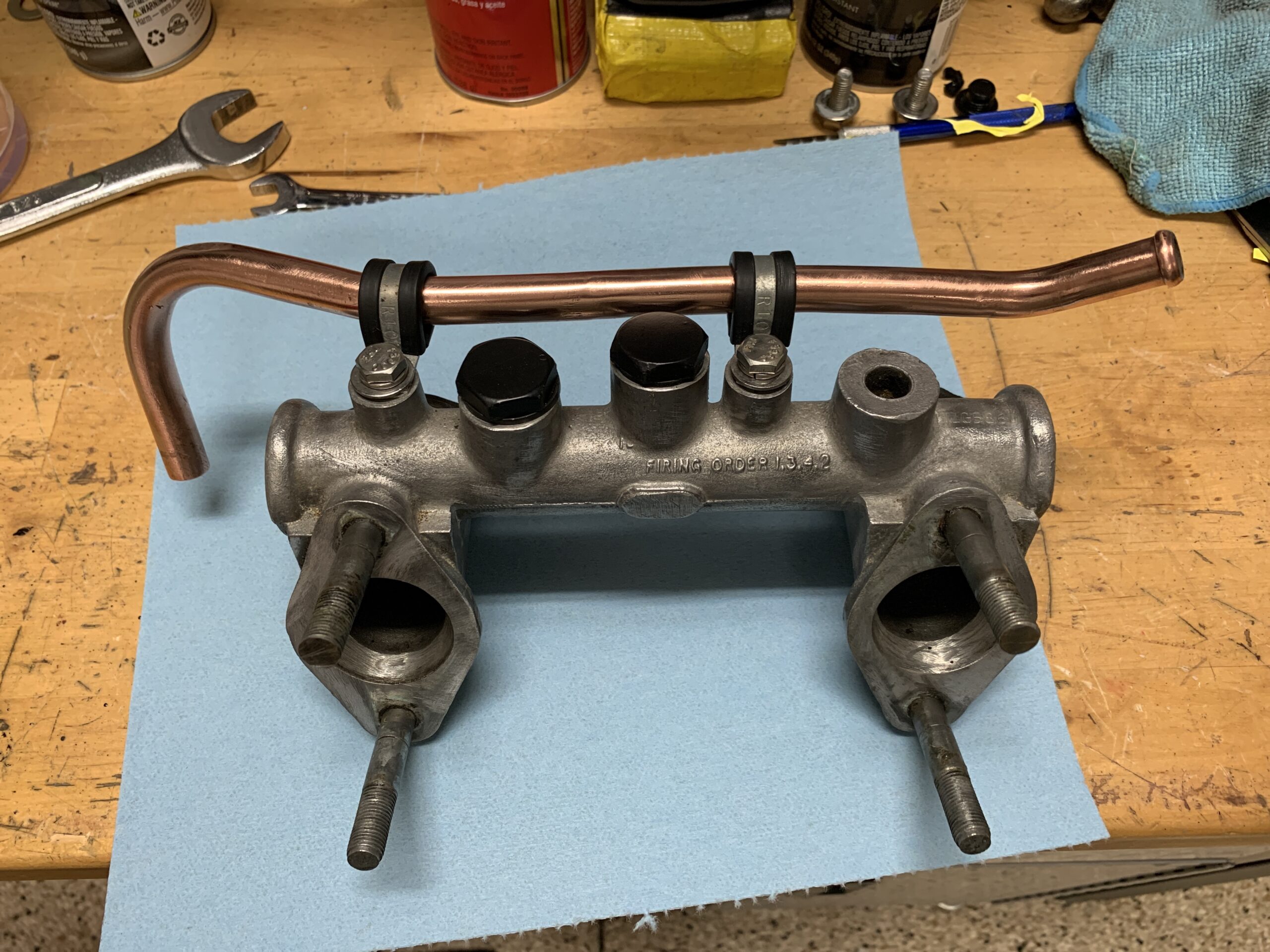
Intake manifold Cleaned and Polished
We may, or may not, try using a 1275 PCV valve on the engine. we won’t decide until after we get the engine running well with the original breather hose to the “Y” fitting at the carbs. Installed new 7/16 inch fuel hose to the breather and will connect it to the PVC valve when the engine is in the car.
New Timing Chain Cover Breather Hose
Purchased a new transition piece that links the intake manifold to the PCV valve. AH Spares had it part number EXENG492.
PCV Transition Piece for Intake Manifold
The throttle and choke return springs, the throttle linkage and the exhaust header brass nuts were all cleaned and prepared for reuse although new springs have been ordered.

Throttle and Choke Return Springs
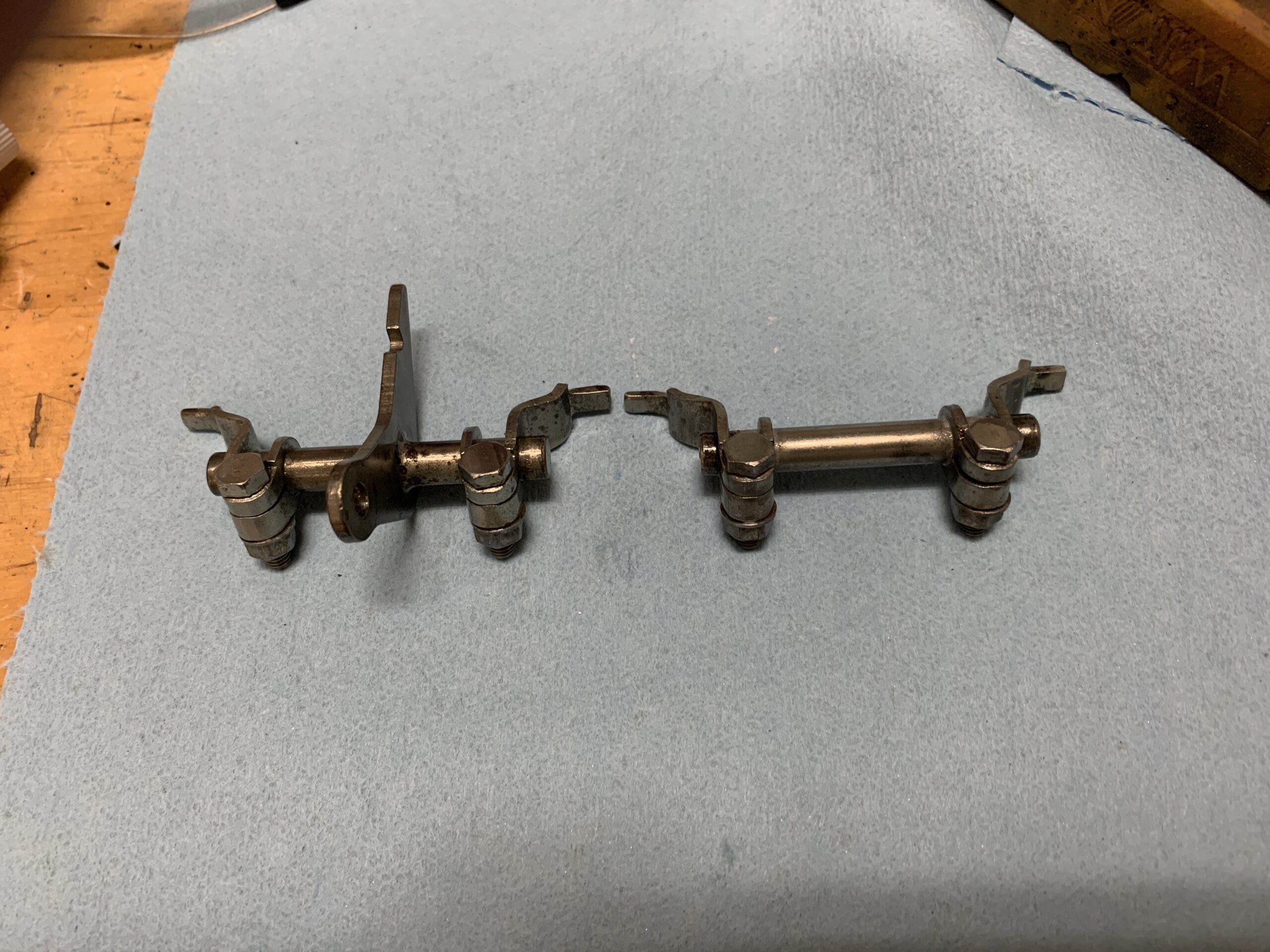
Carb Linkage
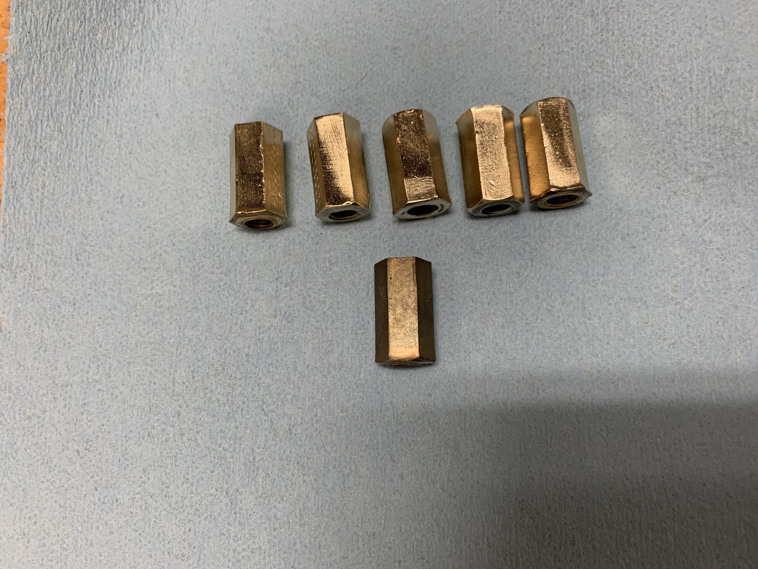
Exhaust Header Nuts Cleaned
The carb heat shield was in pretty good shape but it was cleaned and repainted to be consistent with the engine’s new paint. There are gaskets on each side for a total of four and these were replaced with new items.
Carb Heat Shield
Carb Heat Shield Freshly Painted
heat shield with gaskets
There is a spacer between each carb and the heat shield. Two additional gaskets (for a total of six) are needed to fit between the spacers and the carb bodies. The spacers were cleaned and polished.
Carb Heat Shield Spacers
Spacers with gaskets installed on Heat Shield
Manifold Nuts Ready to Go
Carburetor assembly with heat shield and intake manifold ready for installation once the Engine is in the car. Cleaned KNN air filters are also ready.
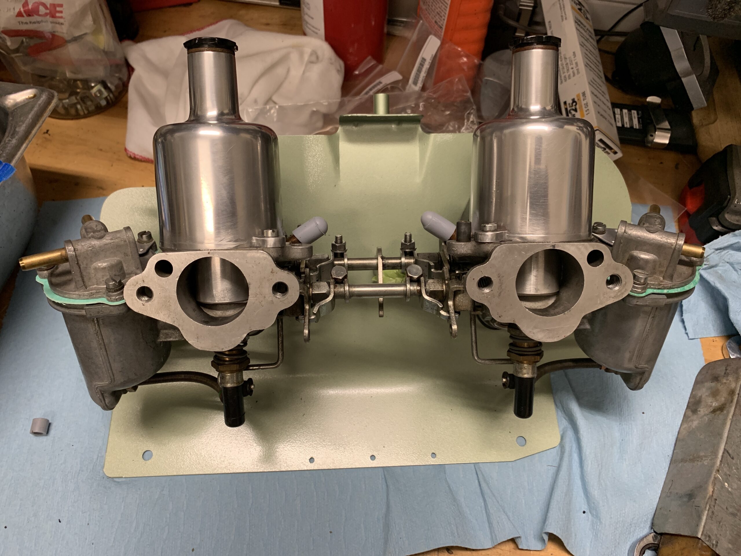
HS2 Carb Assembly Ready to Install
Just to add a little more bling to the engine, the old rubber fuel hose that connects the front carb to the rear was replaced with a new braided stainless steel hose.

New Braided Hose Between Carbs
The image below shows the connection points for the throttle return springs.
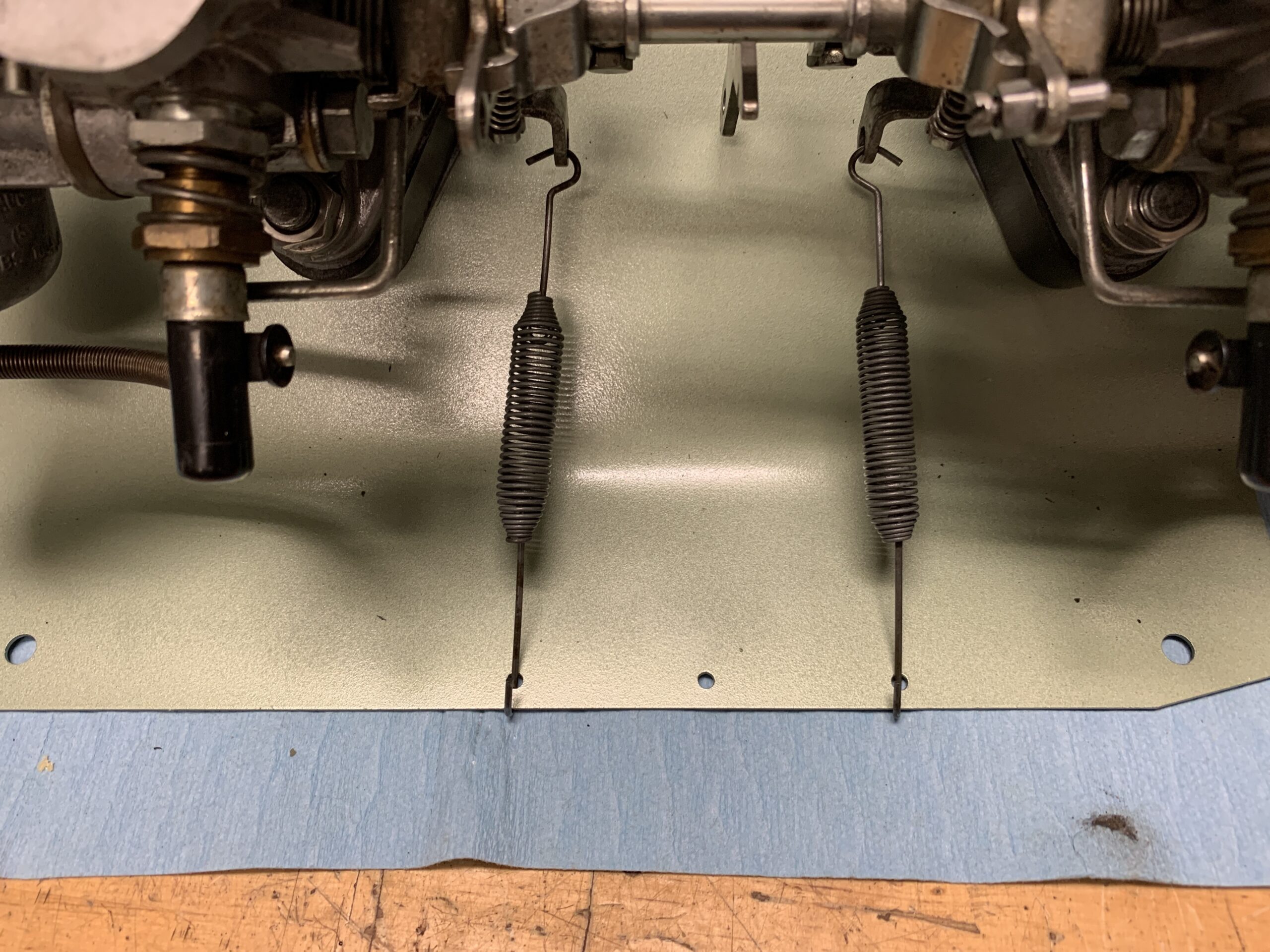
Throttle Springs Trial Fitting
After reinstalling the motor and gearbox in the car, we discovered that the SU Electronic Fuel Pump was leaking. A new pump was ordered from Burlen in the UK. The new pump is exactly like the one taken off the car, model number AUF214.
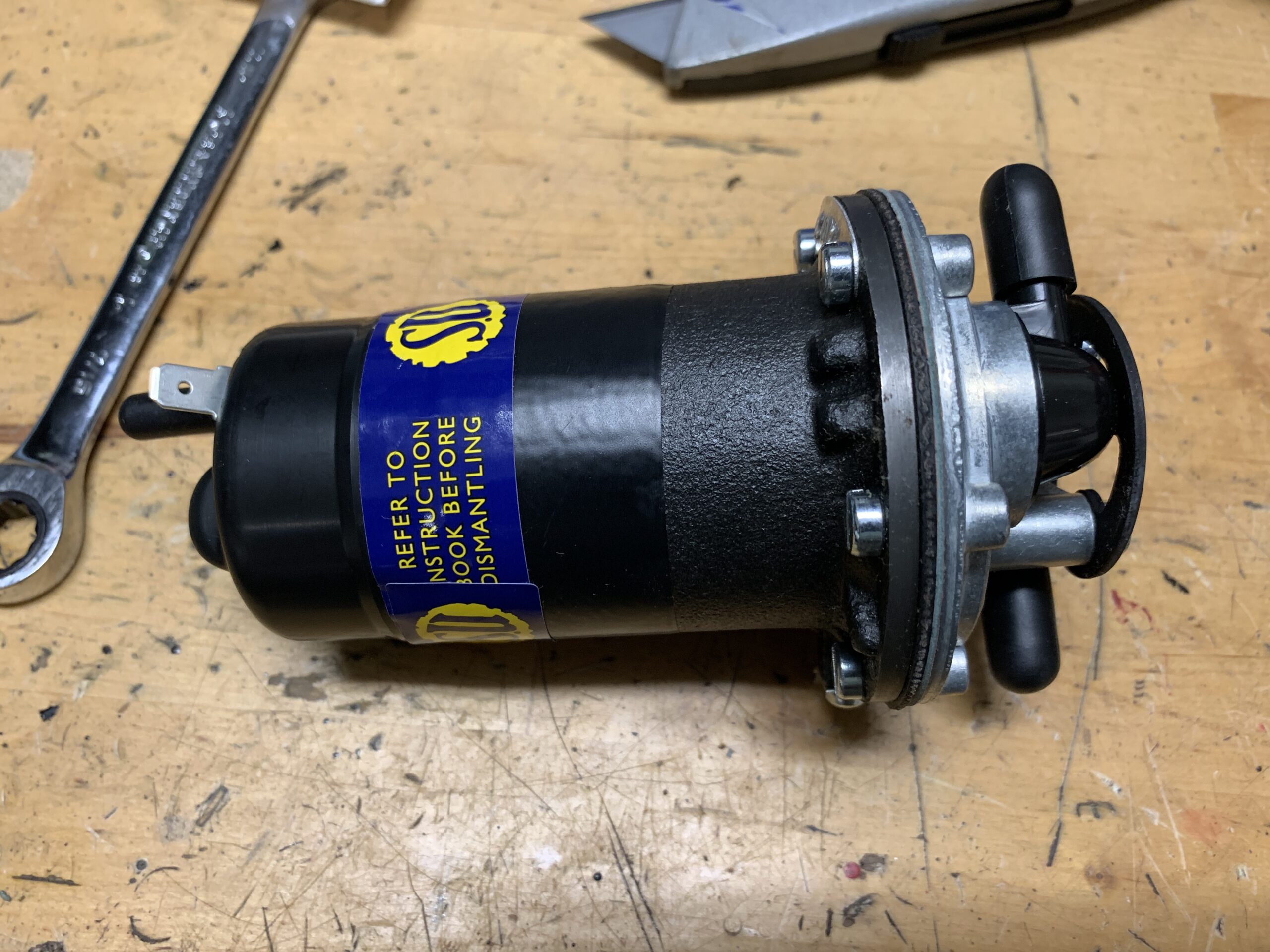
New SU Electronic Fuel Pump
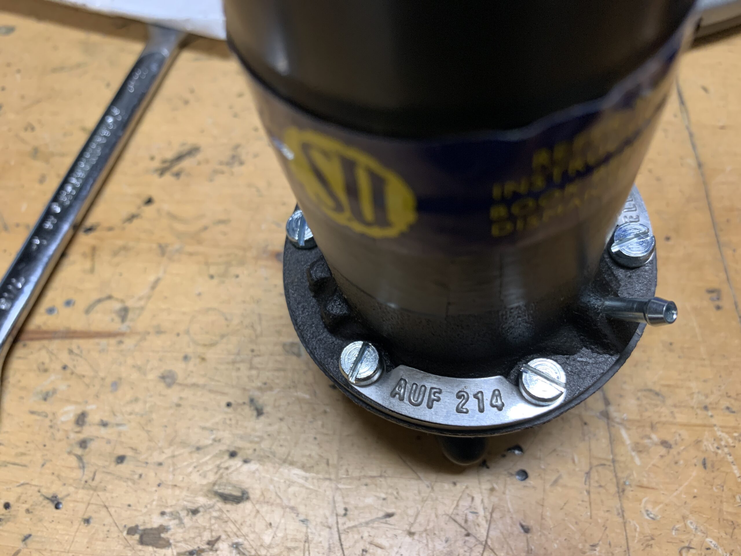
New Fuel Pump Model # AUF 214
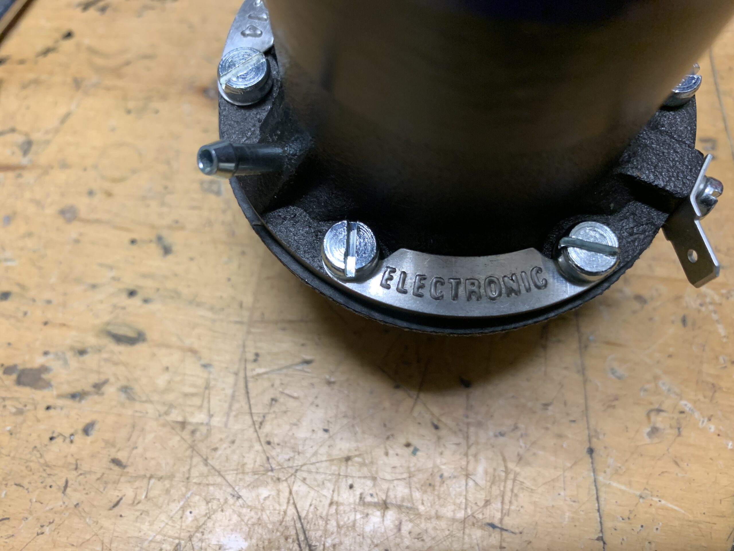
New SU Fuel Pump Electronic Designation
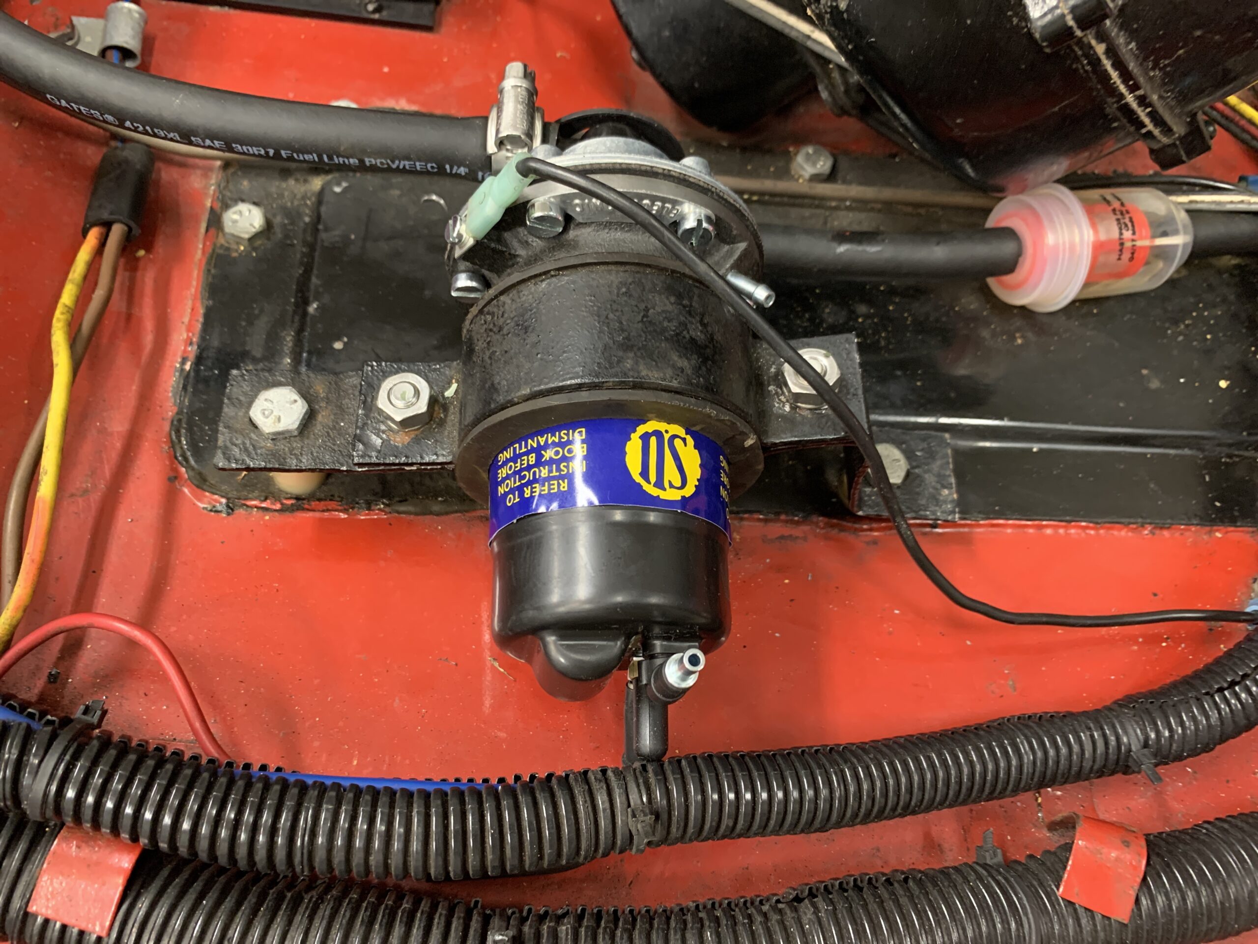
New SU Fuel Pump Installed in Engine Bay
Gauges
The right hand drive connector for the speedometer cable on the Rivergate five speed conversion never worked well. Once the cable came loose and a second time the cable broke.
Rivergate Speedo Cable Adapter
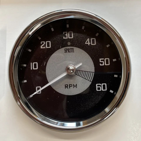
Now seemed to be the perfect time to convert to the GPS speedometer sold by Bugeye Guy.
The unit is made by Speedhut instruments and apparently David at Bugeyeguy.com has a custom face made for the unit to look similar to the original Sprite gauge face. The unit has a number of wires to hook up on the car.
The solid red wire is spliced and crimped to a solid red wire with an inline fuse. The other end of the wire is spliced to a solid 18 gauge red wire that runs behind the dash and over the RH bonnet hinge cavity, out the rubber grommet in the firewall and down to the fuse block on the switched ignition side.
The red/black wire from the speedometer follows the same path as the red wire. It is spliced into an 18 gauge wire and travels over the hinge cavity through the rubber firewall grommet and down to the battery (always hot, constant power) side of the fuse box.
The white wire for the gauge light is joined with the white wire from the power inverter into one bullet connector. The bullet connector is then plugged into a four way connector immediately behind the dash fascia close to the sliding panel light switch.
The blue wire from the speedometer runs behind the LH interior kick panel down to the dipper switch and joined with the terminal with the green wire. When the high beam lights are triggered a red LED light illuminates on the face of the speedometer gauge.
The black wire, which is joined with the red and black wire from the speedometer, the single black wire emanating from the back of the speedometer, and the black wire from the inverter were joined together in one bullet connector and then joined with a four way rubber connector with a ground wire to the firewall. These three black wires provide ground to the Speedo, the inverter and the high beam signal.
The wire coming from the speedo that has a snap connector is joined with the inverter wire. The inverter is a small 1”x1” black cube that is fastened to the back of the dash fascia with a 3M sticky pad just to the left of the steering column. As mentioned above, the black wire from the inverter goes to ground, and the white wire goes to the panel lights near the panel light switch.Speedhut Speedo and Tach Instructions
Finally, the gps sensor wire is screwed into the fitting on the back of the speedo and routed behind the dash facia to the LH side. It is then routed between the door and the polished aluminum dash trim and is secured to the top of the dash with a magnetized plate.
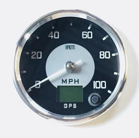
Bugeye Guy GPS Speedometer
Bugeye Guy Speedo GPS Sensor
We liked the speedometer so much that we ordered the matching tachometer too! Many of the electrical connections for the tachometer take advantage of the wiring loom provided with the speedo so that the tachometer can piggy-back for shorter wiring runs. Really happy with both of these upgrades. At first glance, the new instruments do look very much like the originals.
Bugeye Guy Electronic Tachometer
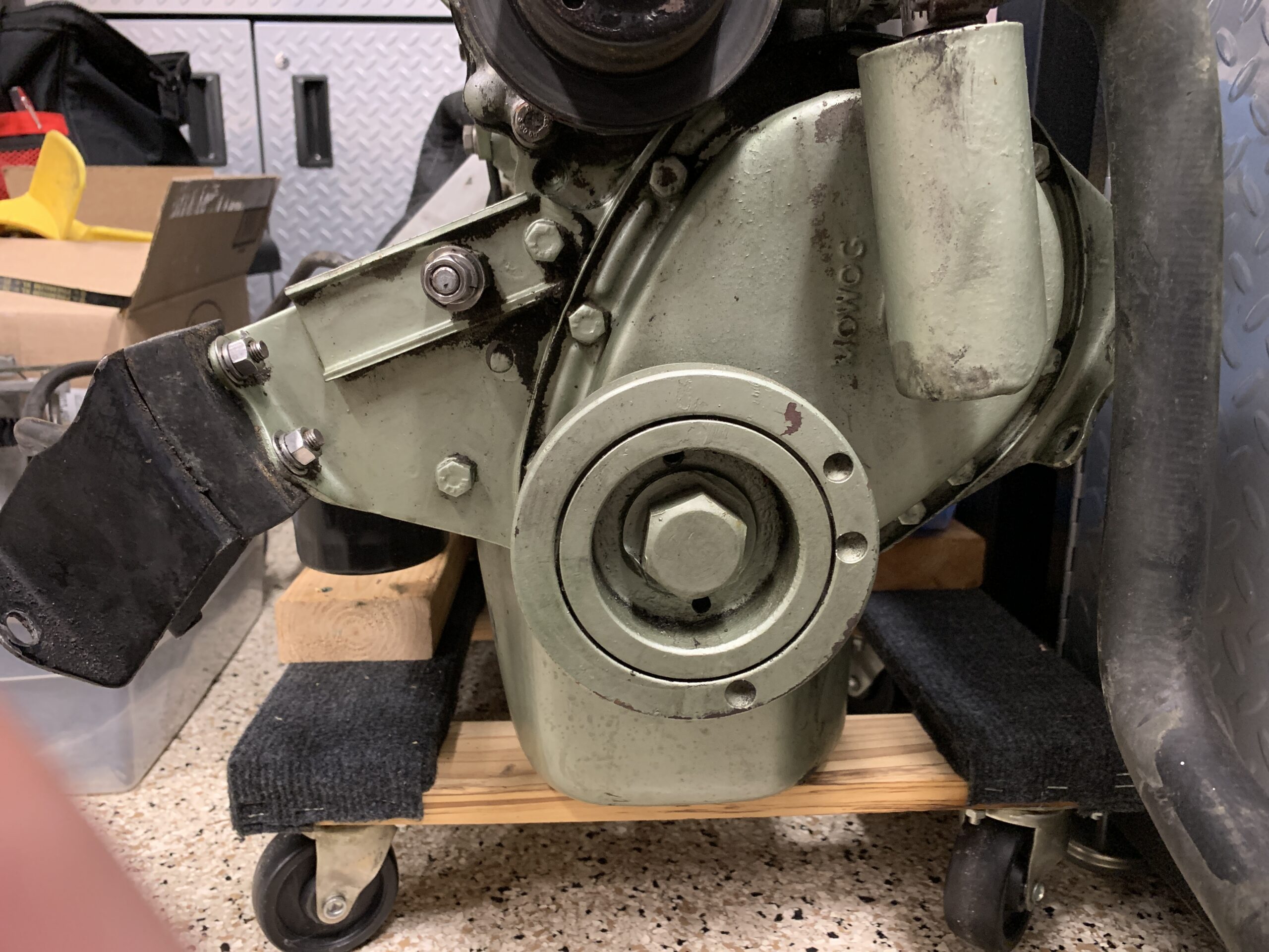
Gearbox
I was going to separate the gearbox and the engine but decided to leave them mated. I did, however, clean the gearbox and paint it.
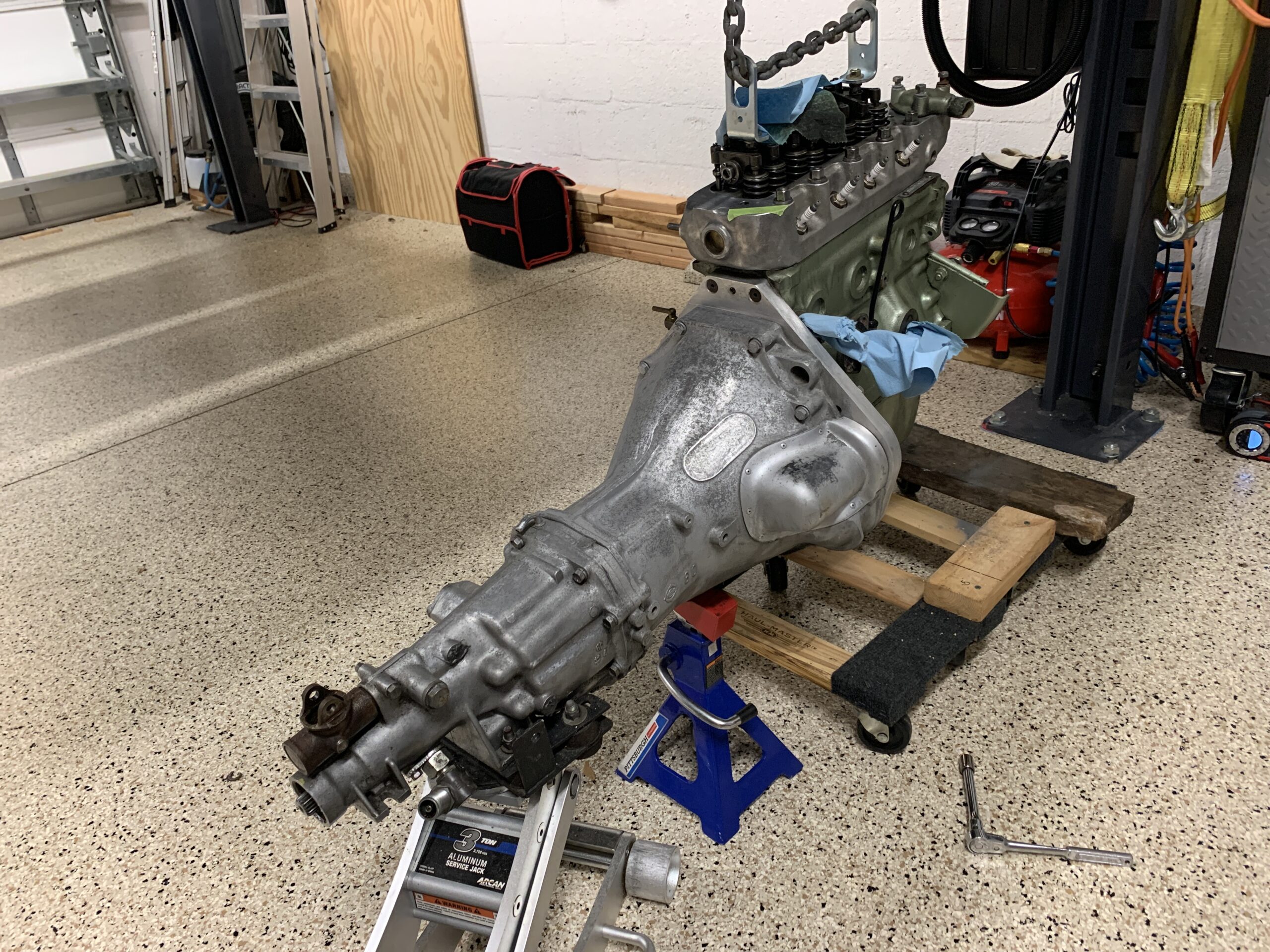
Gearbox to be cleaned
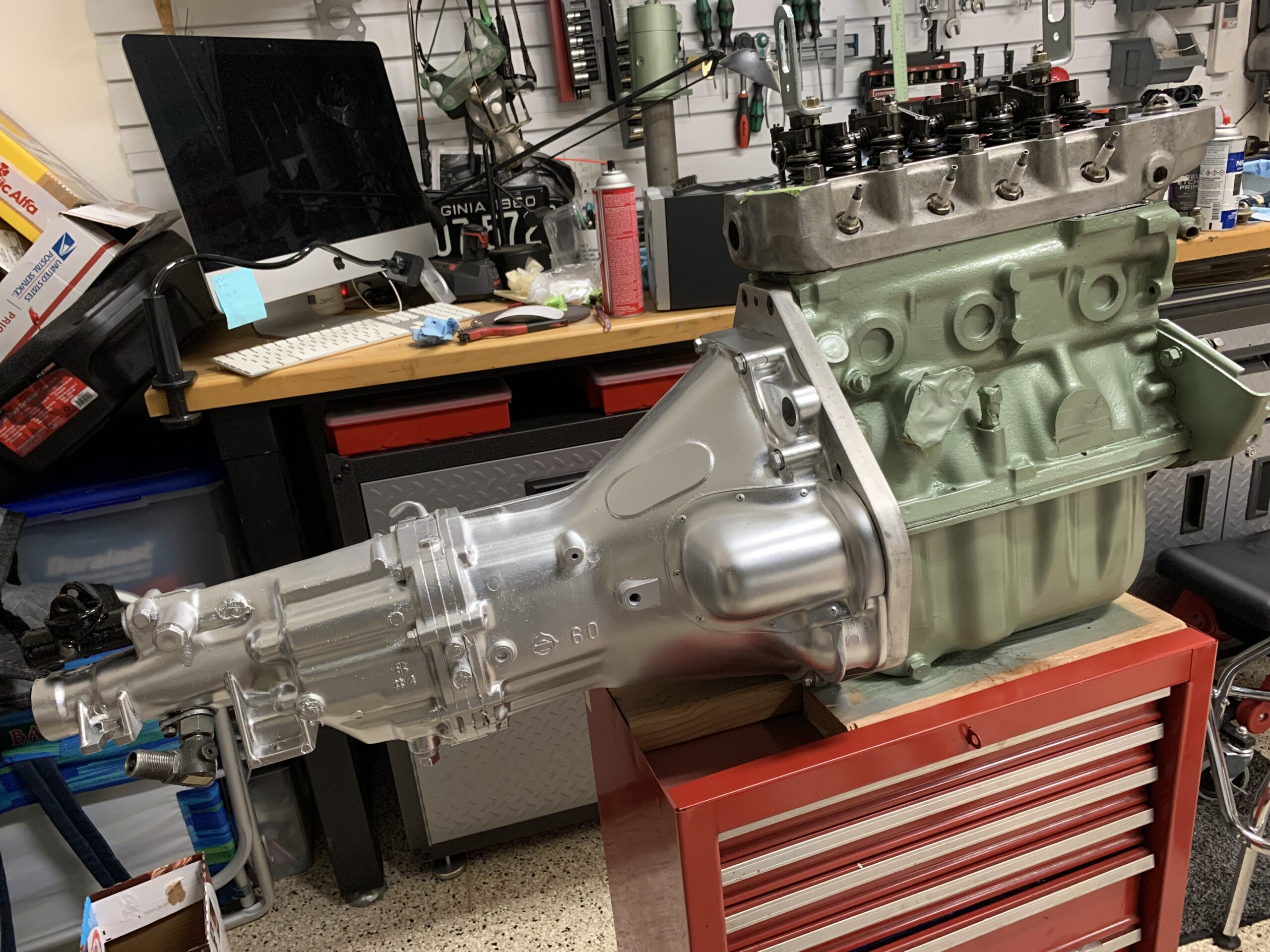
Gearbox Cleaned and painted
The Rivergate gearbox mounting bracket needed to be inspected, cleaned and painted. The mount consists of two components. To remove the transmission mounting bracket you first have to loosen the two bolts for the lower bracket and then remove the piece that attaches to the transmission. Installation is the reverse.
Gearbox Mount Two pieces combined
Upper Gearbox Mount Piece
Following removal, the components were cleaned, the old paint was stripped and the brackets were repainted and installed.

Rivergate Gearbox Rear Mounting Brackets cleaned and painted
Rivergate Gearbox Upper Bracket Installed
Rivergate Gearbox Lower Bracket Installed
Heater
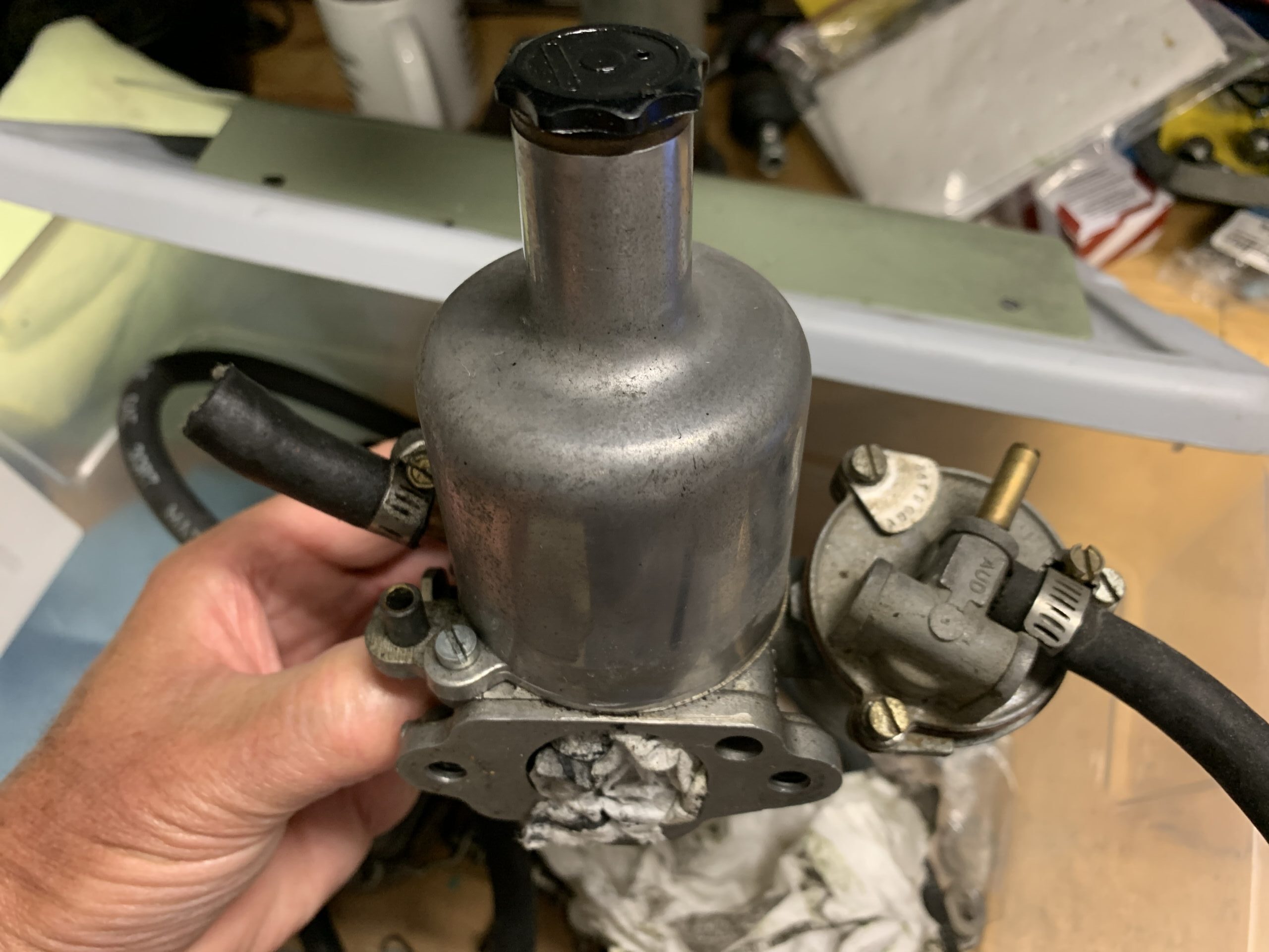
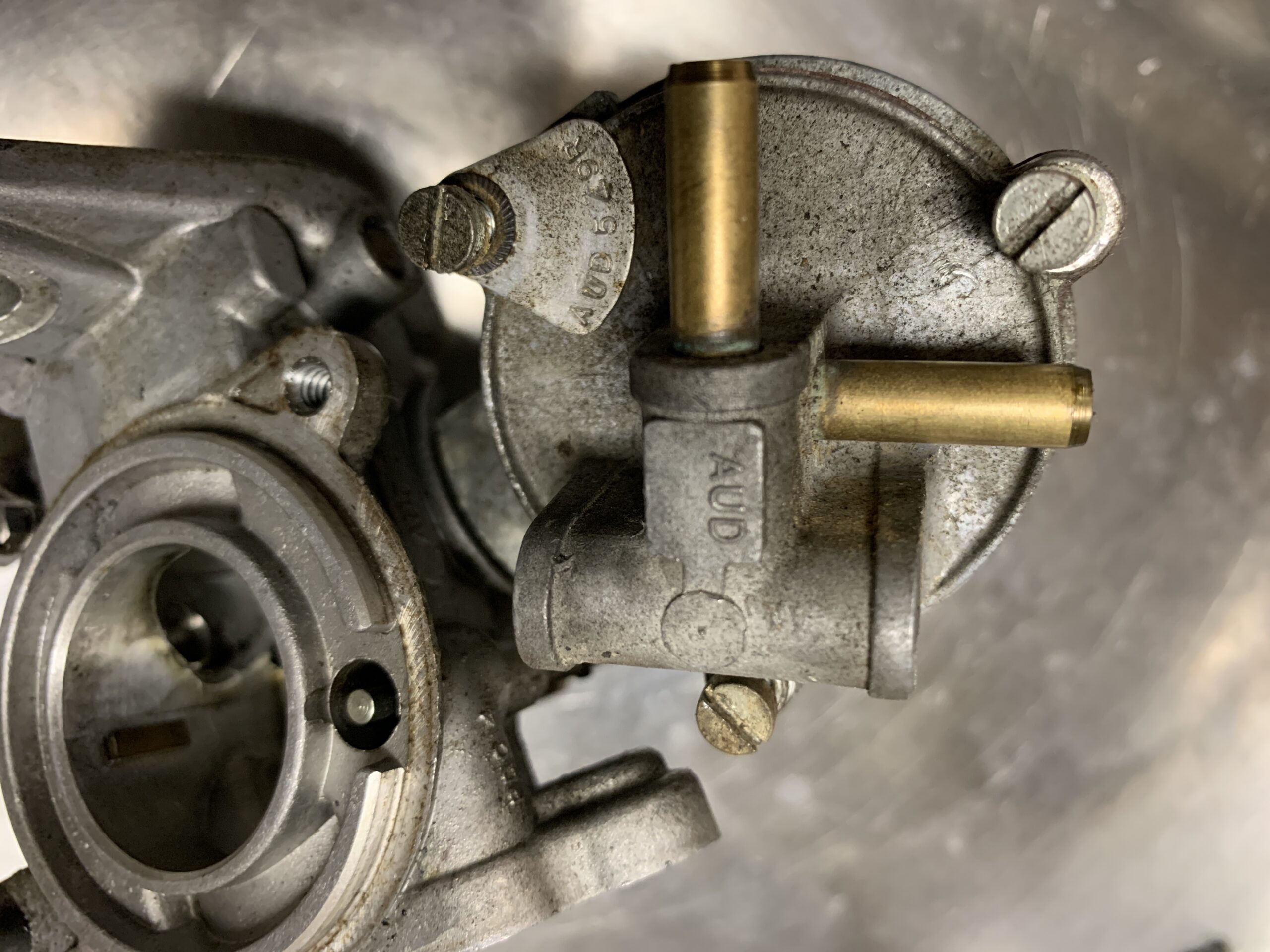
Hot water to the heater box is controlled by a water valve located on the top rear of the cylinder head. Rather than cleaning the original, the valve and its gaskets were replaced with a new one sourced from Bugeyeguy.com. The same sealant that was used on the water pump was used in this application too.
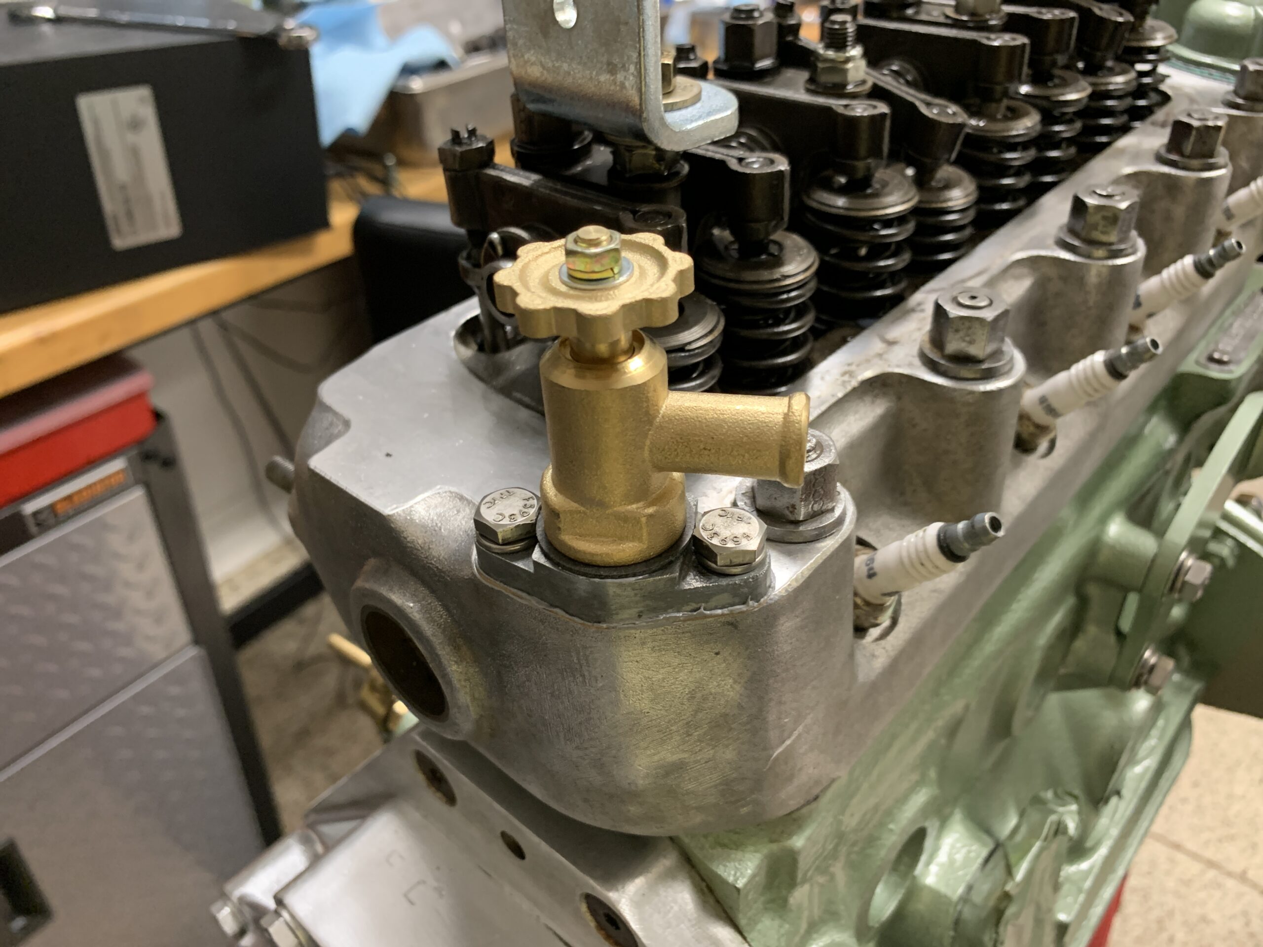
Heater water valve
Water Hose from Valve to Heater Box
Removed the heater blower and it’s mounting brackets from the car. We used 320 grit sandpaper followed by 600 grit to remove the corrosion and then painted the entire assembly glass black.
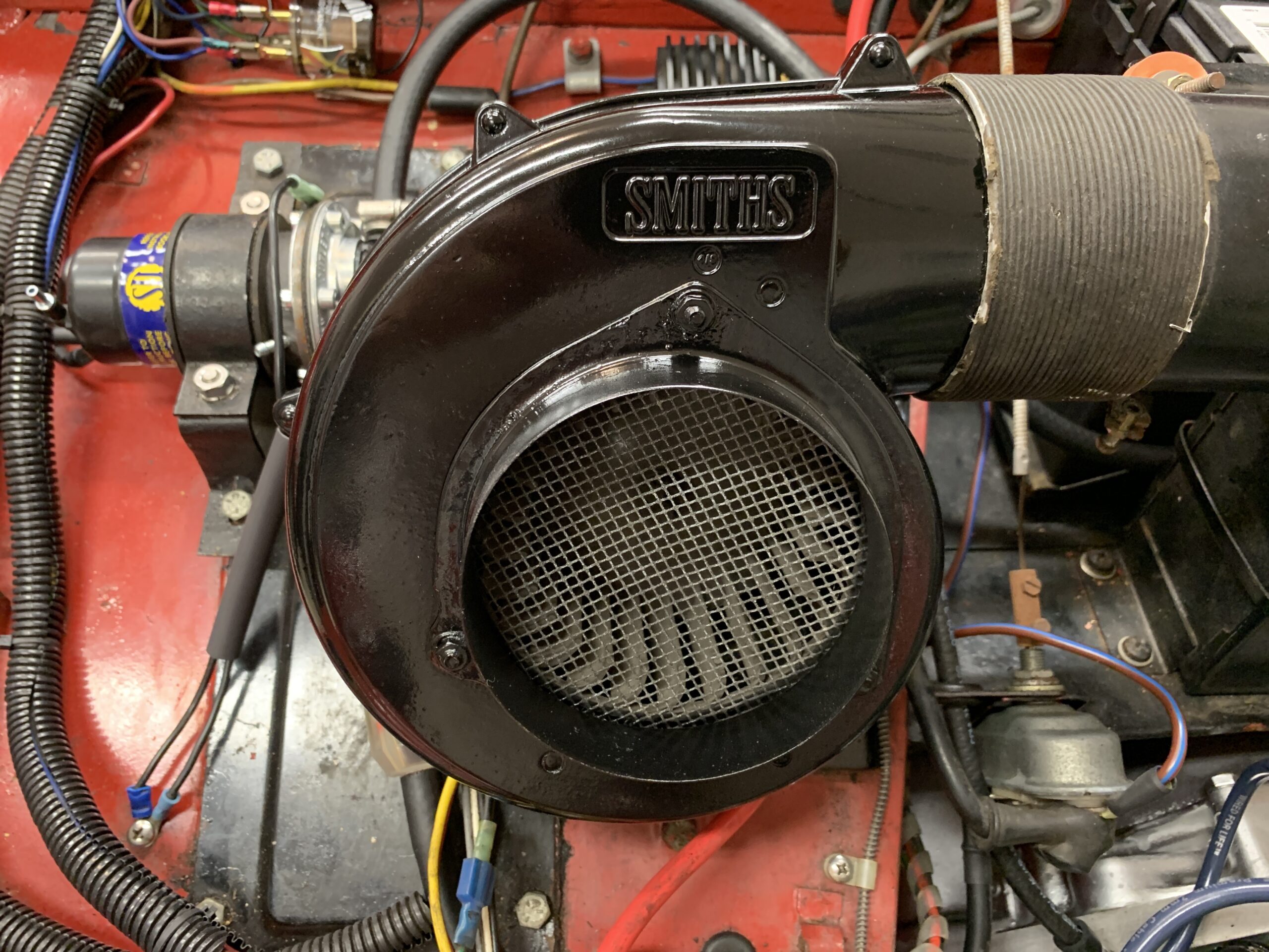
Heater Blower Cleaned and Painted
A new air duct pipe and “P” clip, sourced from Bugeye Guy, was installed. One of the original clamps at the blower was reused, but at the front flange a new modern clamp was used because of fit issues. The process is to bend the hose as close to 90° as one can and secure it to the front flange. Then, roughly place the P clip over the hose where it mounts to the fender and route the hose to the blower. Cut the hose to length and then secure the P clip. We had to bend the hose a little bit to form it so that it would not conflict with the alternator pulley. The handle of a large screwdriver was used to do that deed.
New Air Duct Pipe
Ignition
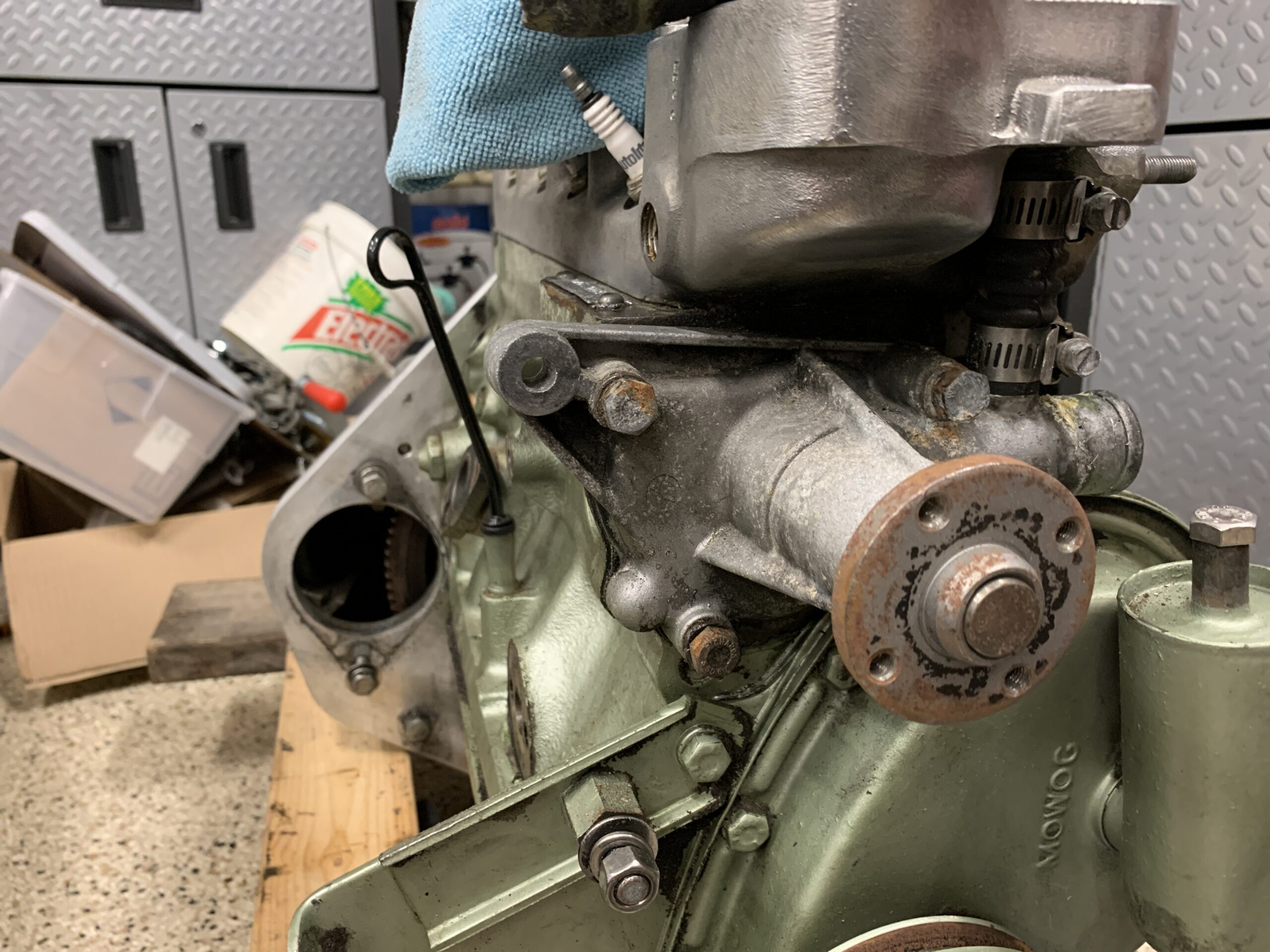
We replaced the spark plugs with the same brand and type that were in the engine when it was delivered from Rivergate. These were Autolite #4164 gapped to .25″. We may switch these out later after we do some more research on the subject. A little anti-seize was applied to the plug threads.
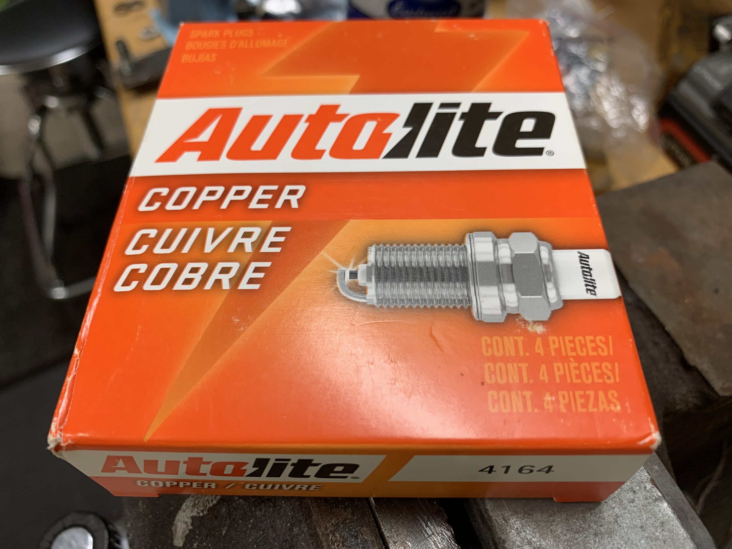
Autolite 4164 Spark Plugs

New Spark Plugs Installed
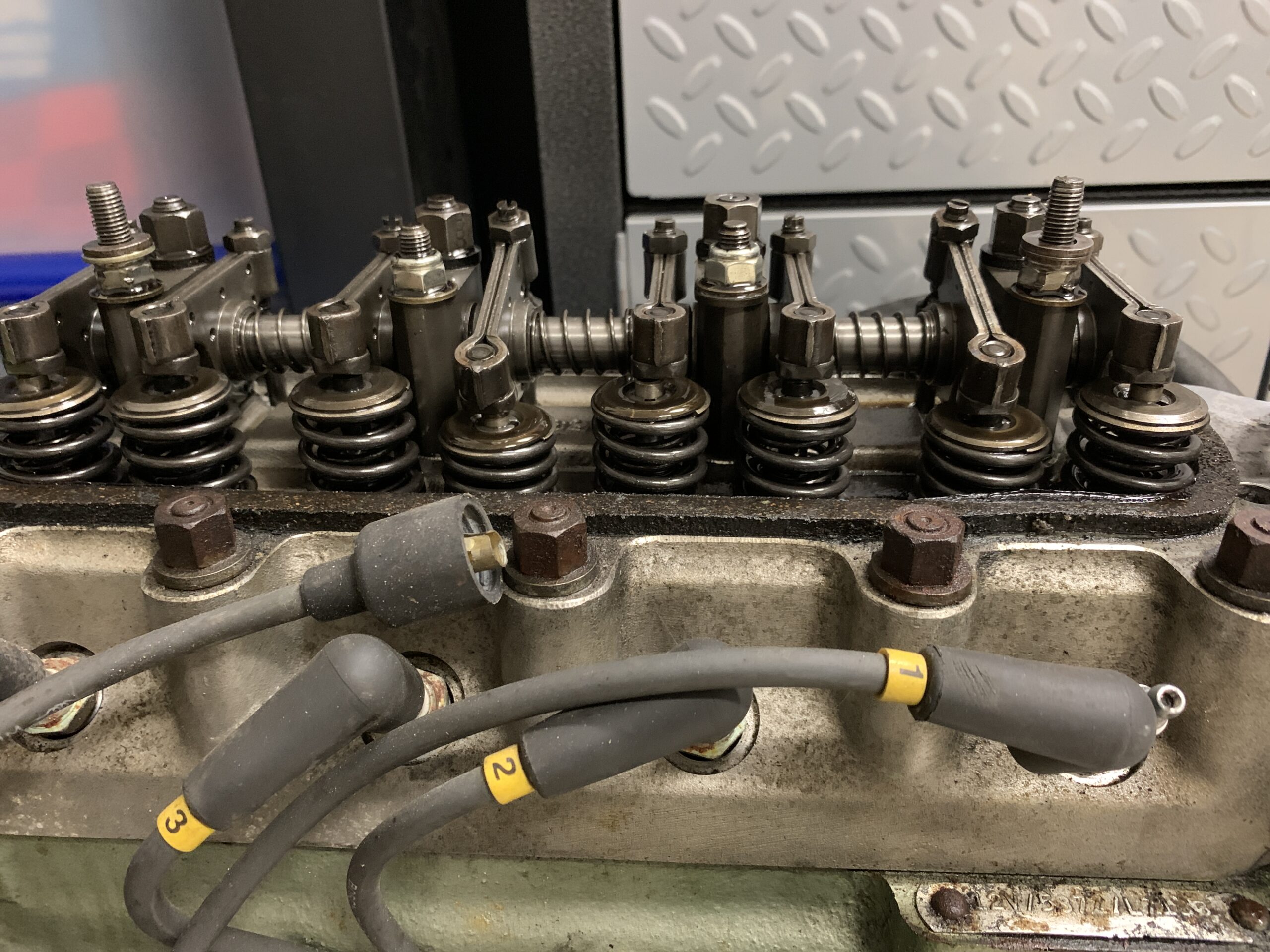
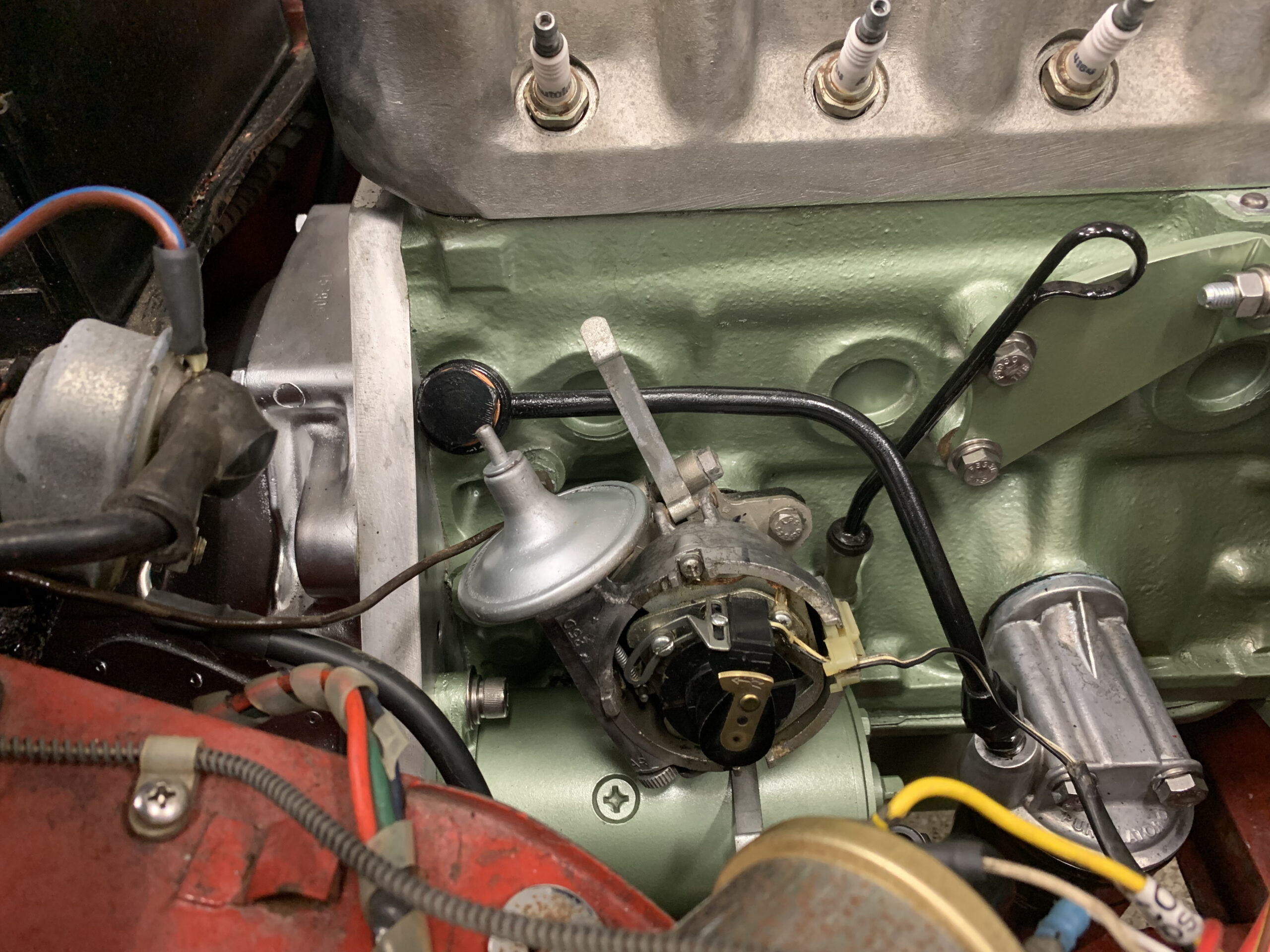
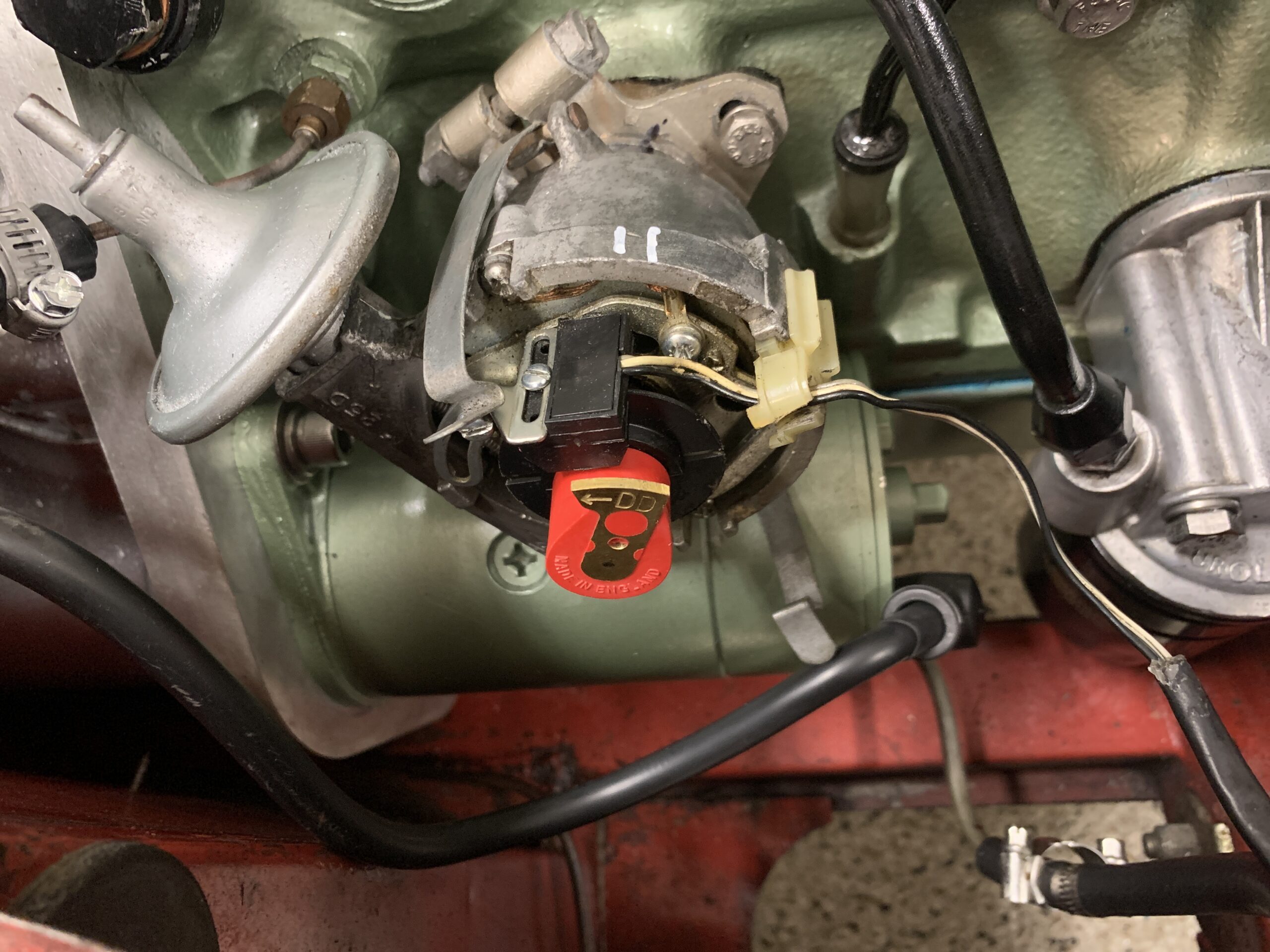
The Bugeye uses a Crane XR700 “FIREBALL” electronic ignition system that employs an optical sensing technology. The unit is still sold in 2021 but the technology is now owned by a new company and is now called FAST XR700. It has been in the car for close to twenty years and still functions properly. This photo shows the internal components of the system in place:
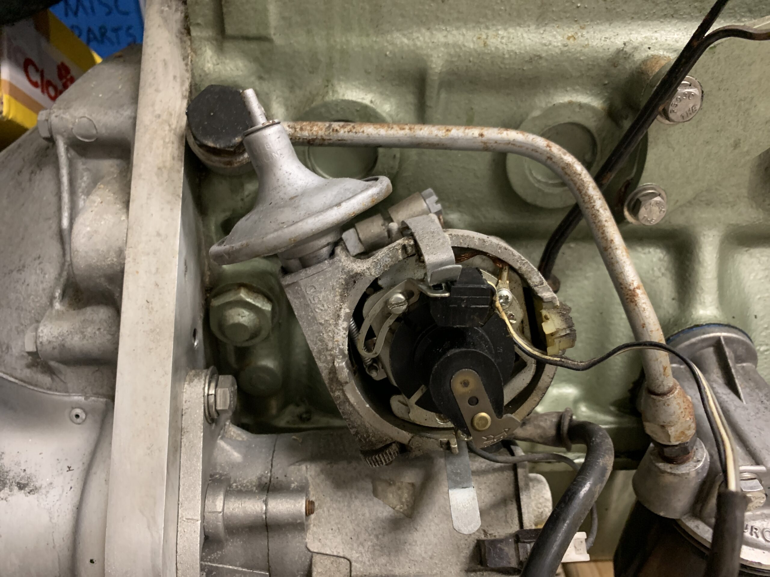
Crane XR700 Electronic Ignition
The distributor and wiring were removed and cleaned. The distributor is secured with a mounting plate.
Loosening the large screw on the right side of the clamp allows one to rotate the distributor to retard or advance the timing. If the screw is loosened sufficiently the distributor can be pulled out of its housing and removed. If this is done, care must be taken to mark the distributor and the mounting plate so that the distributor can be returned to the same position without effecting the ignition timing.
Distributor Clamp Bolt

Distributor Clamp
Distributor Timing Position Mark
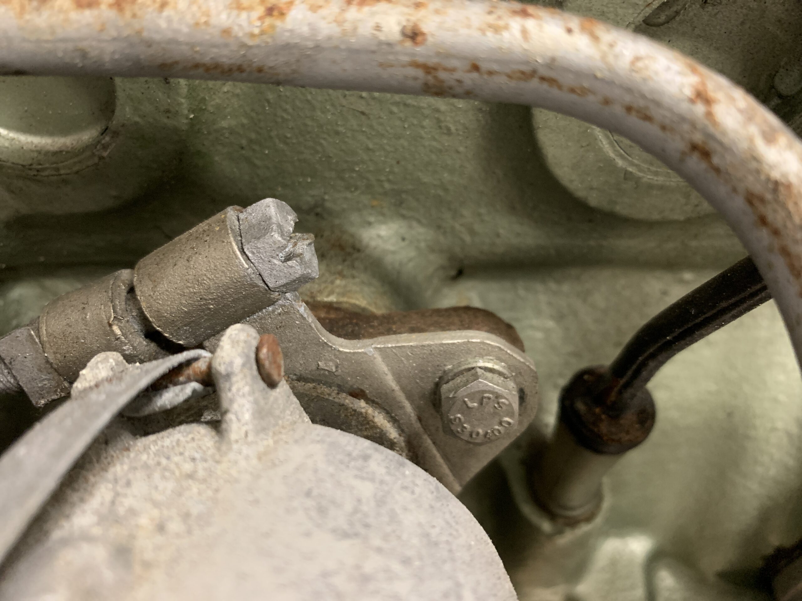
Alternatively, the distributor can be left in the mounting plate to avoid any chance of effecting the ignition timing and the distributor and the mounting plate can be removed as one, together, by loosening two 1/4″ hex head bolts that secure the mounting plate to the engine block. The LH (rear) bolt is a bit hard to access. A crow’s foot wrench or a custom made tool helps to do the job.
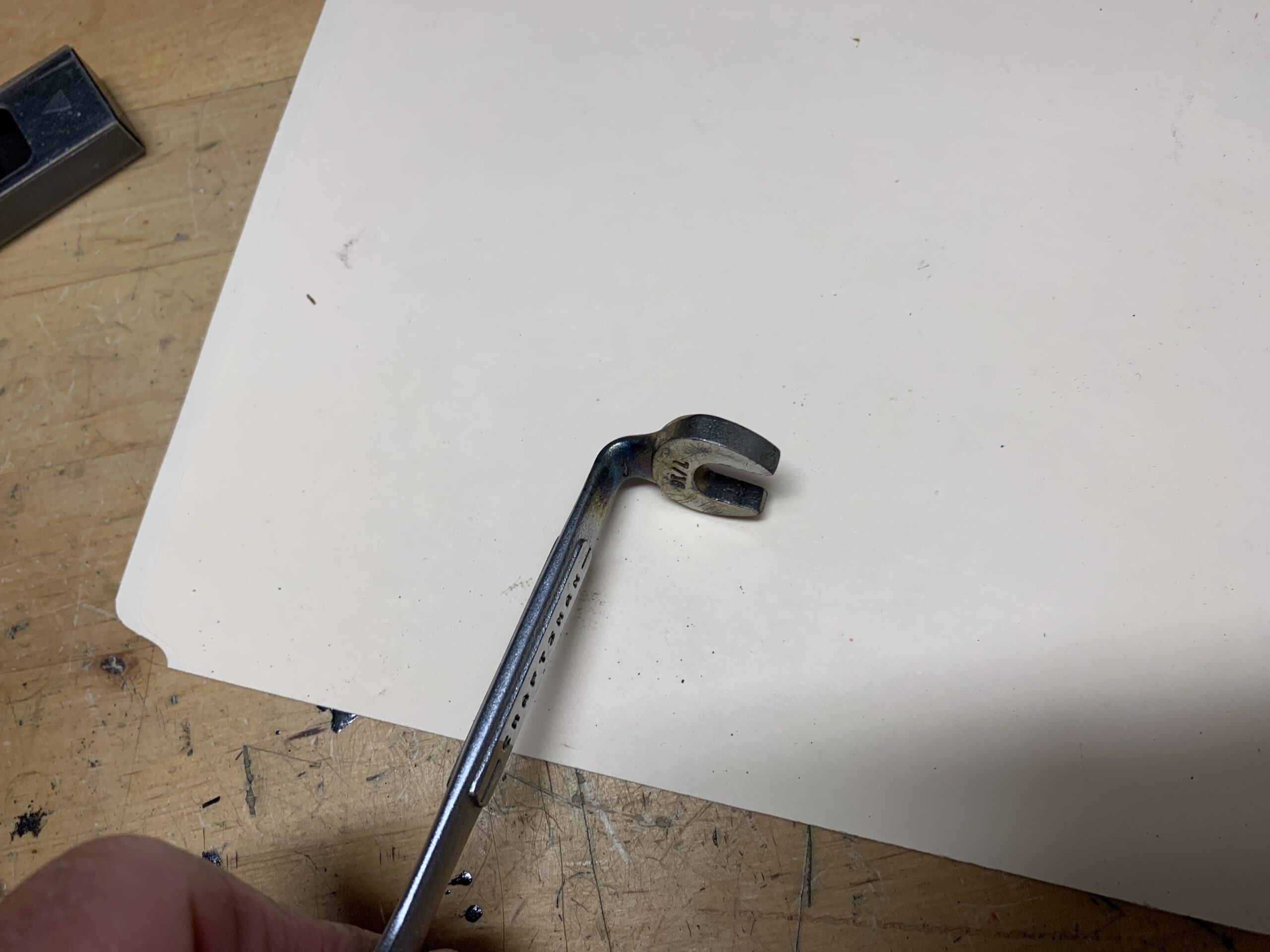
Modified 7/16 wrench to Remove Distributor
Distributor and wiring Before Cleaning
The distributor can only be installed into the engine block one way. The drive dog at the bottom of the distributor shaft must align with the fitting in the engine oil pump drive. It doesn’t show well in this photo, but the slots in the fitting are off center. If the crank is turned it is possible to get the timing out 180 degrees so care must be taken to make sure these stay aligned.
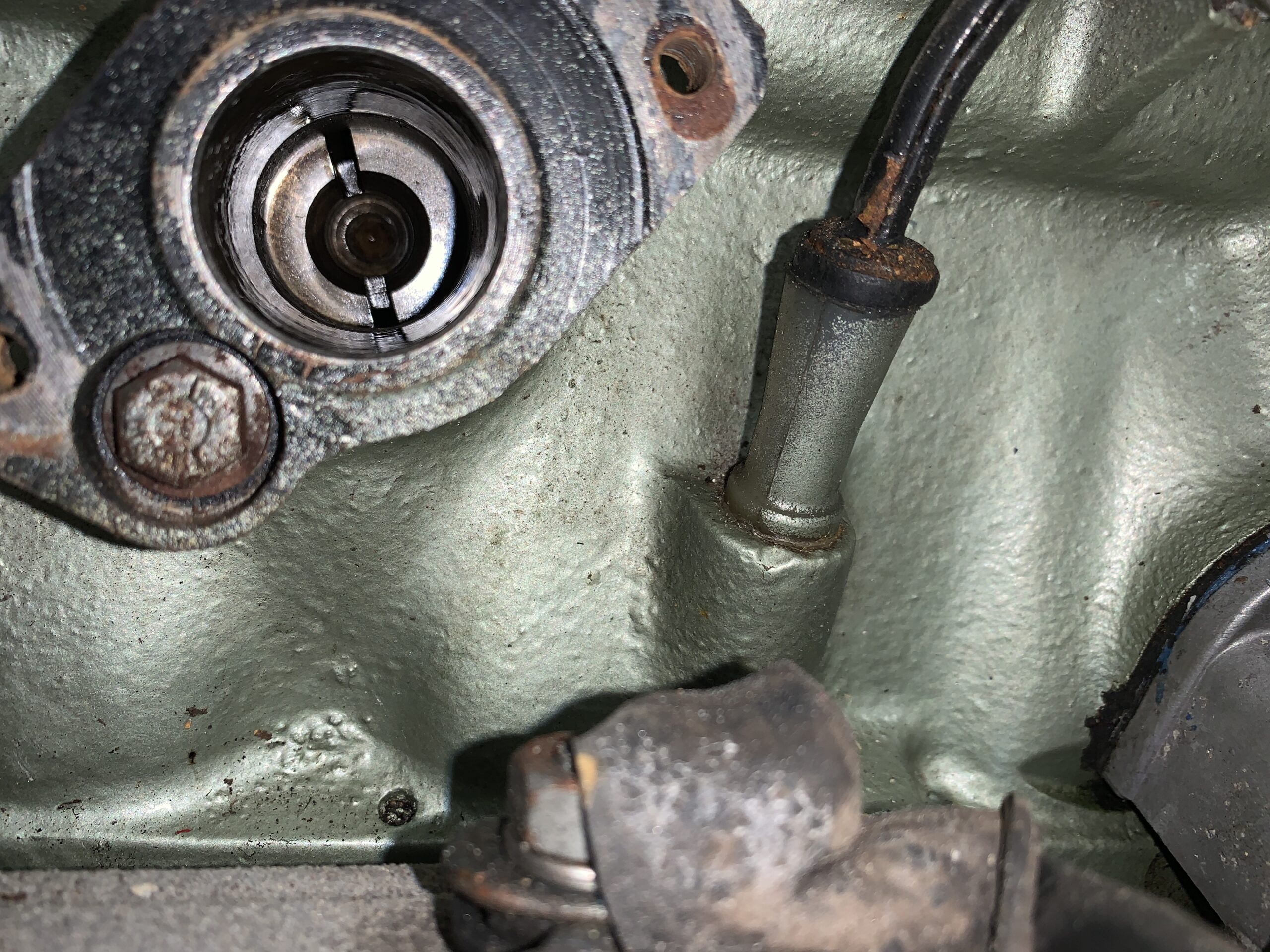
Oil Pump distributor drive fitting
#2 and #5 valves compressed when distributor is removed.
Valve Position When Distribbutor is Removed
Valve Position When Distributor is Removed
Note orientation of key on spindle.

Distributor key into Drive
This photo shows the crank position when the distributor is removed:
Crank Pulley Position when the Distributor is removed
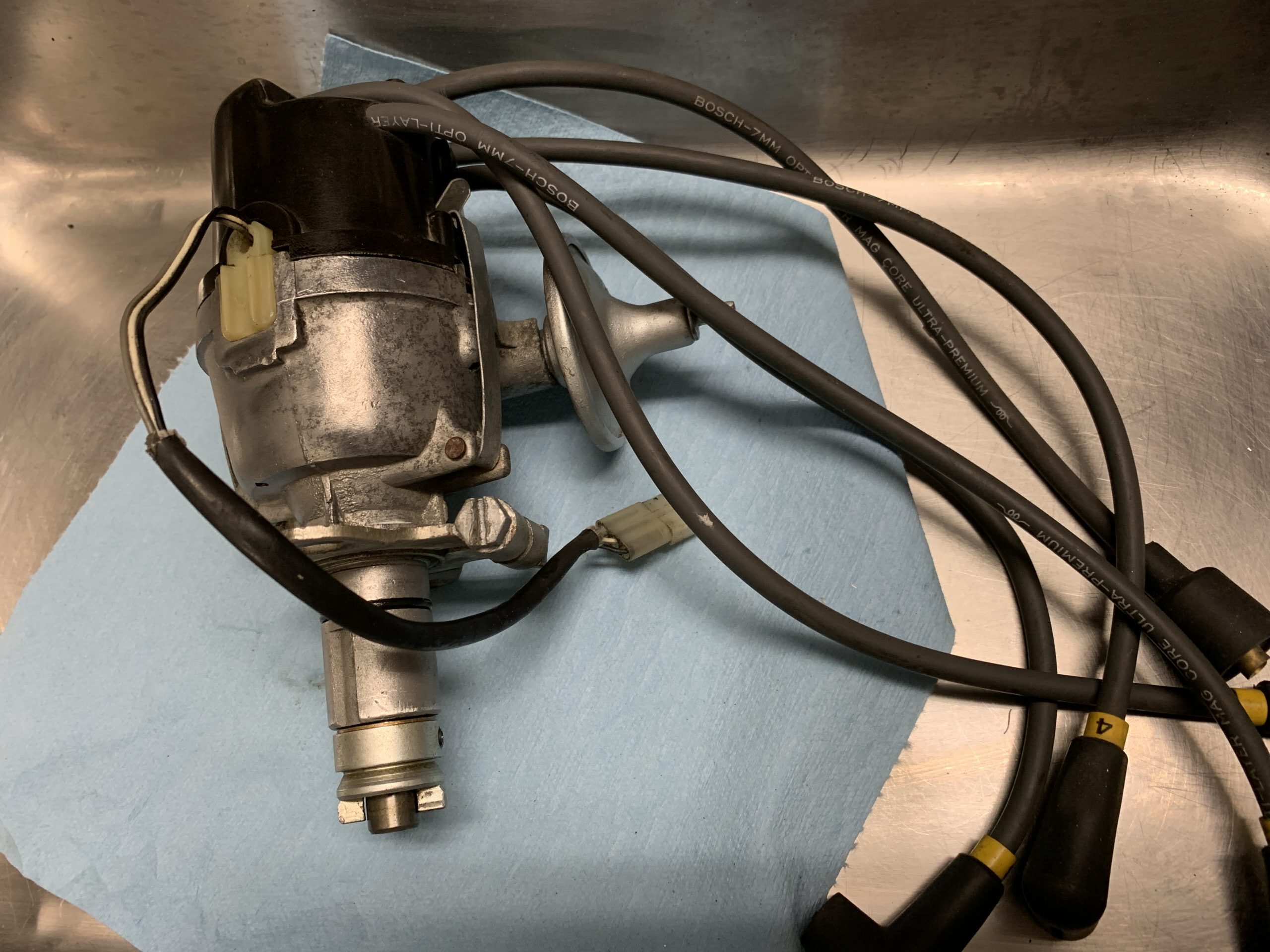
Distributor Assembly Cleaned and Polished
Upon reinstalling the distributor in the motor I also installed a new rotor, top loading distributor cap and new ignition wires from the cap to the spark plugs. Unfortunately, I didn’t get a photo of this.
It is, of course, important when replacing the ignition wires that the wire on the number one firing position on the distributor cap gets connected to the number one cylinder spark plug. The firing order of the engine is 1-3-4-2 in a counterclockwise rotation

Rear Axle, Driveshaft and Differential
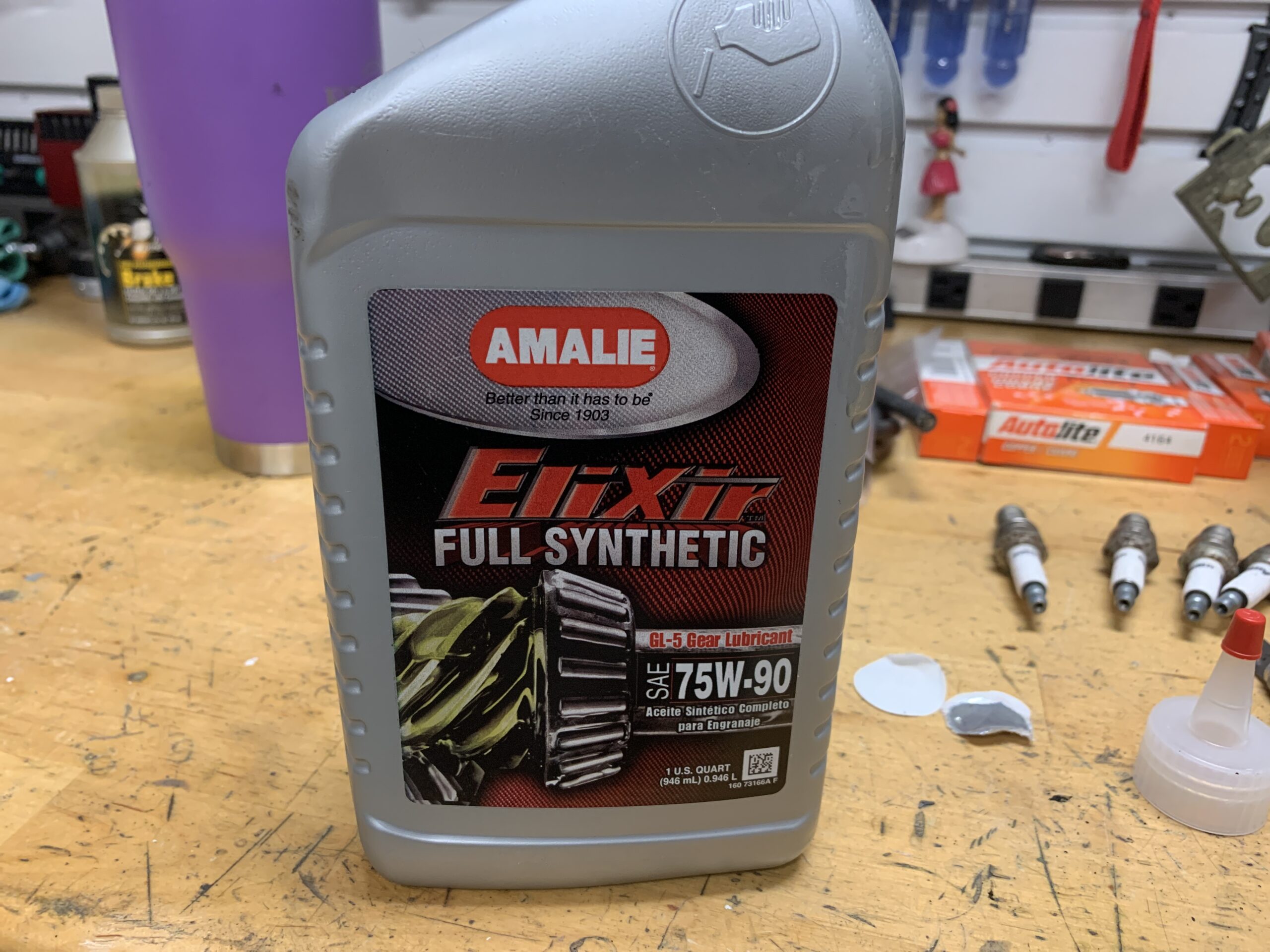
The Axle oil was drained and renewed with Amalie Full Synthetic 75W-90.
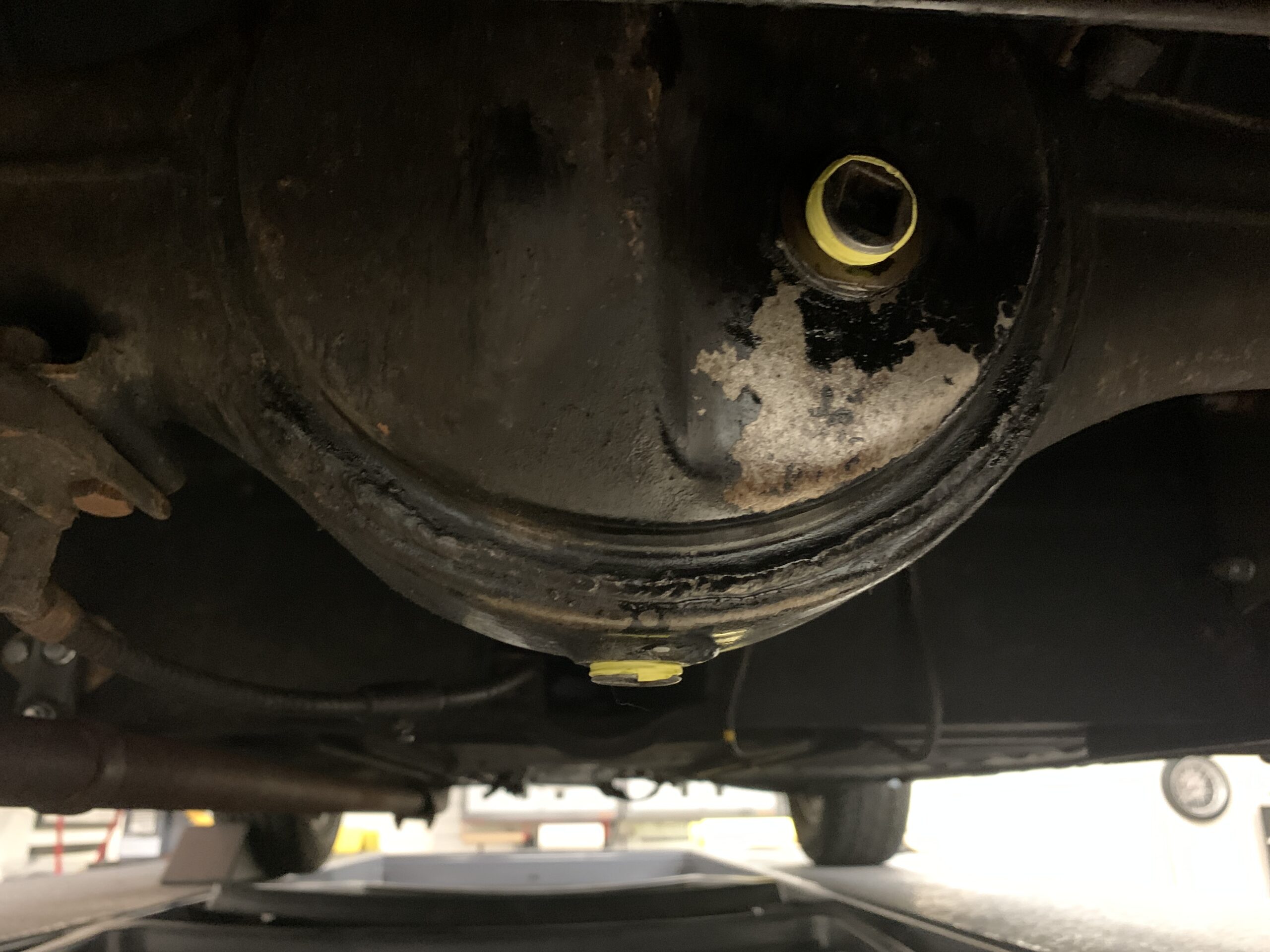
Rear Axle Oil Filler and Drain Fittings
Rear Axle Gear Oil
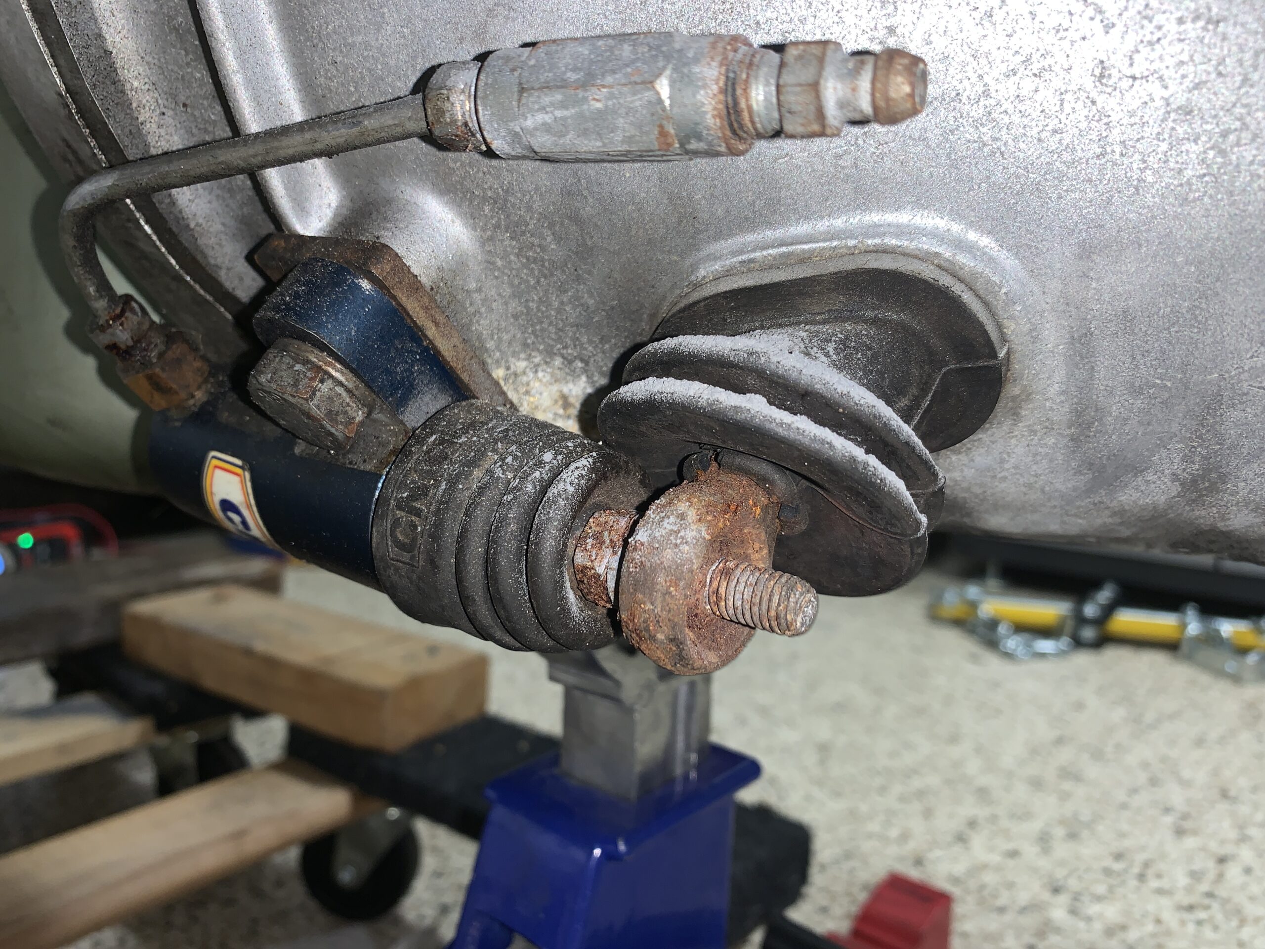
The driveshaft was removed to check the universal joints. Both the front and rear joints seem fine but while the driveshaft was out we went ahead and sanded it as smooth as possible and painted it with POR 15.
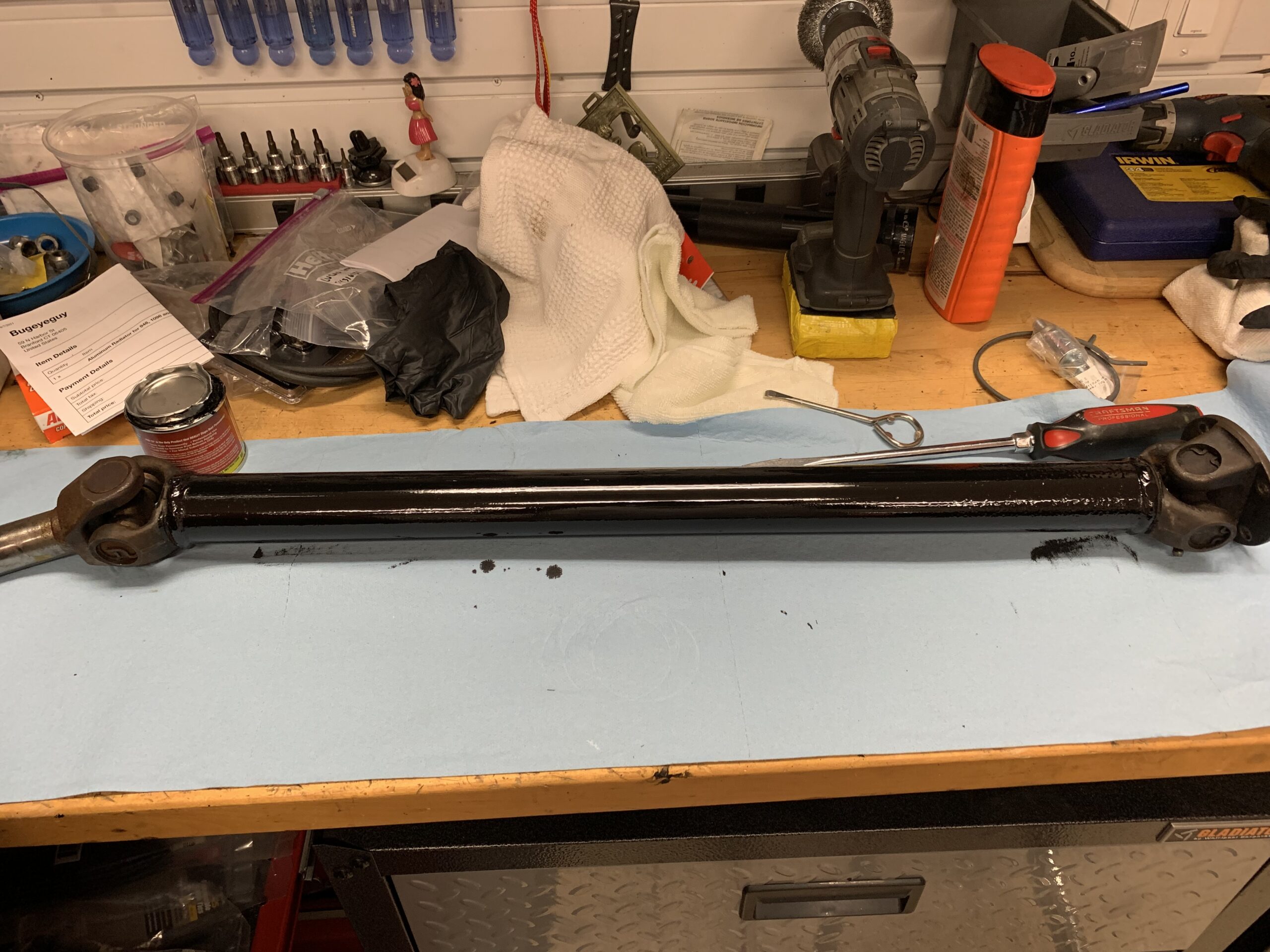
Driveshaft Cleaned and Painted
Rear Suspension
The radius arm bushings in the rear suspension can often be worn. We took the opportunity to go ahead and replace both radius arms with new items sourced from Bugeye Guy. The two rear bolts are special round head bolts with flats that lock into place. One of these was missing and a previous owner had replaced the proper bolt with a regular hex head bolt. Dad was able to find the correct bolt on-line and replaced the improper one.

Radius Arm Proper Bolt
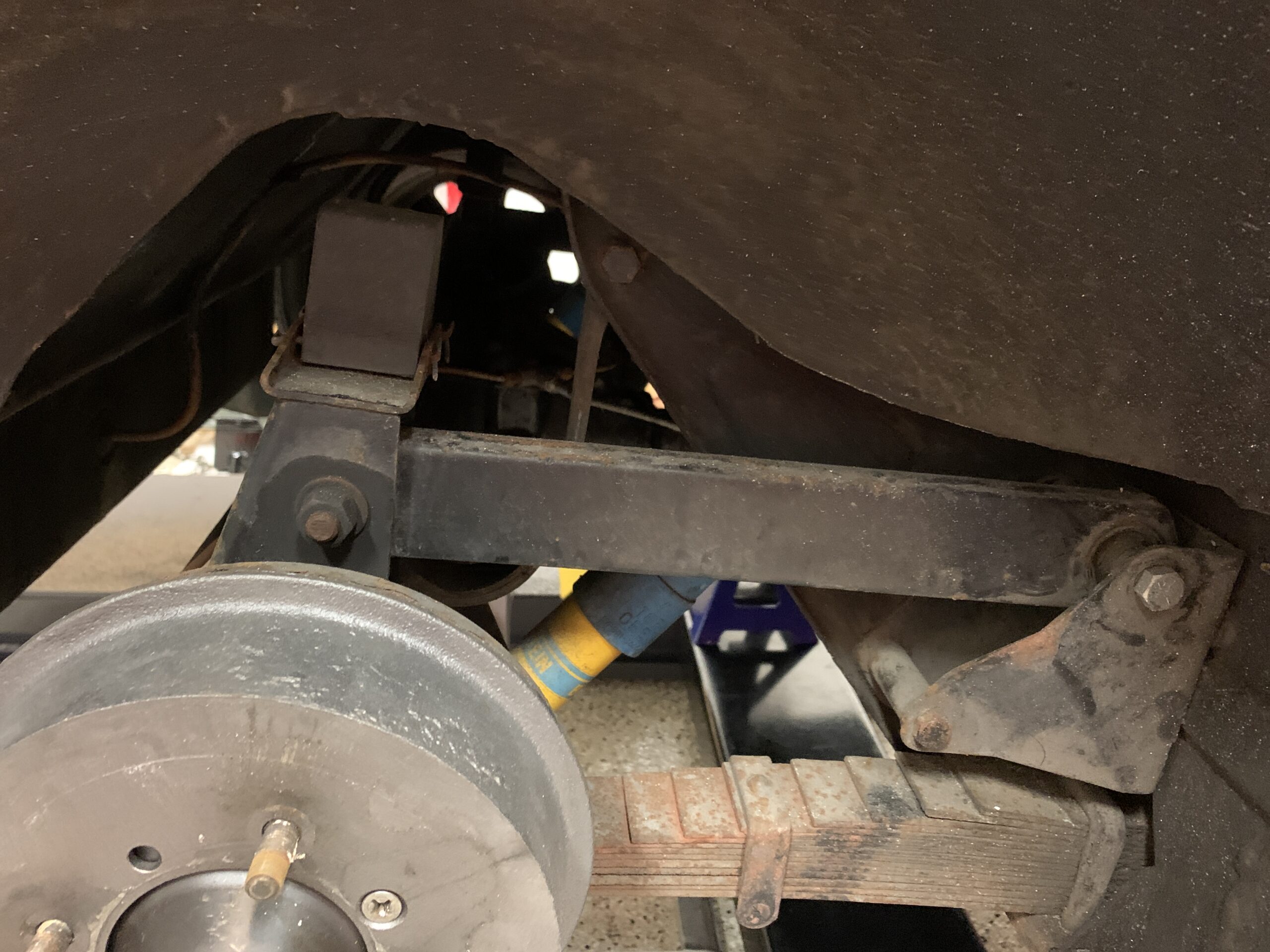
Radius Arm Removal
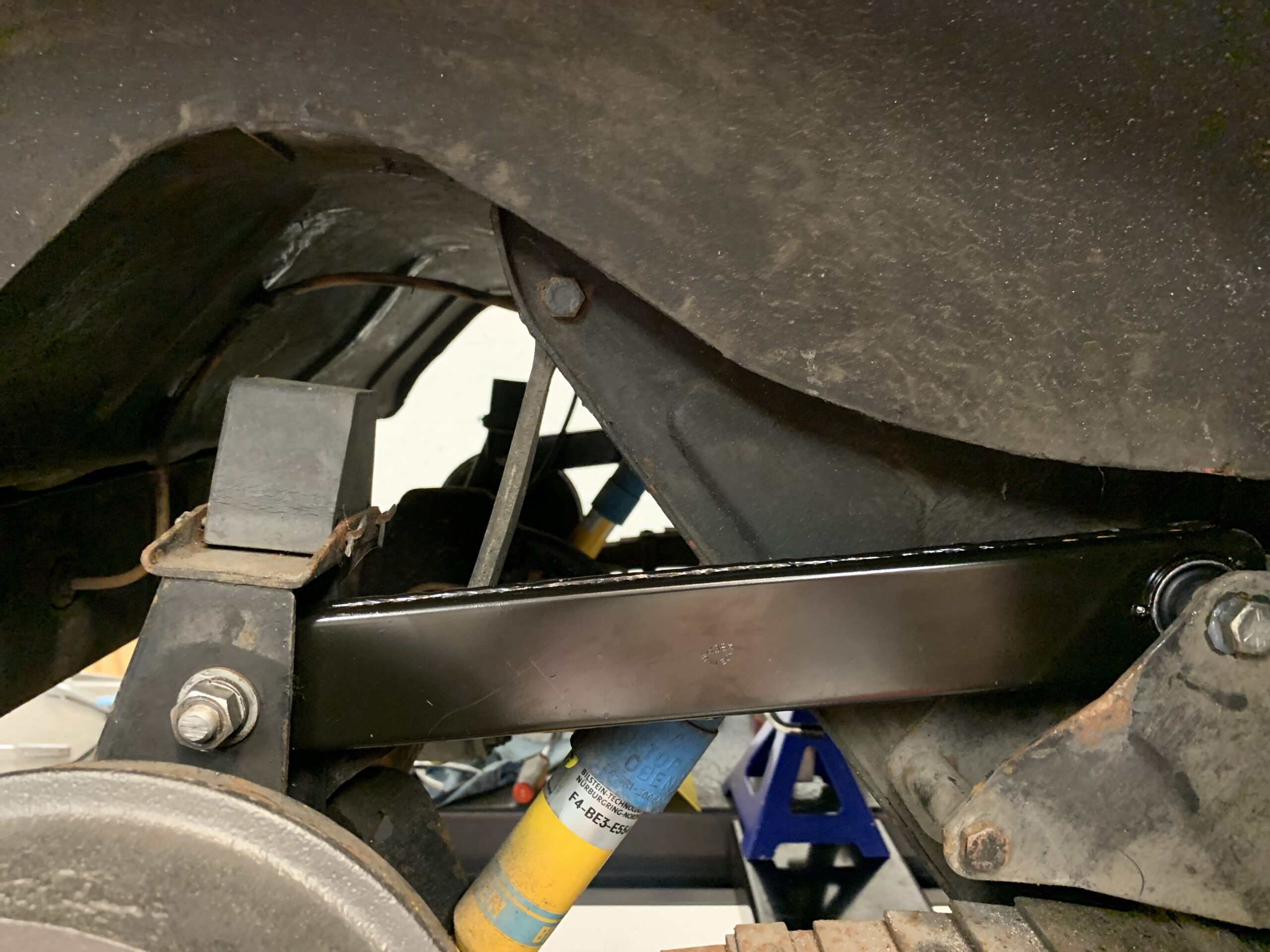
New Radius Arm Installed
Steering
The installation of the engine is simplified if the steering shaft is disconnected from the steering rack and pulled upward. Upon doing so, we discovered that the securing bolt threads were pretty mangled so a new bolt was ordered. However, one could not be located in the U.S., so it had to be ordered from AH Spares in the UK.
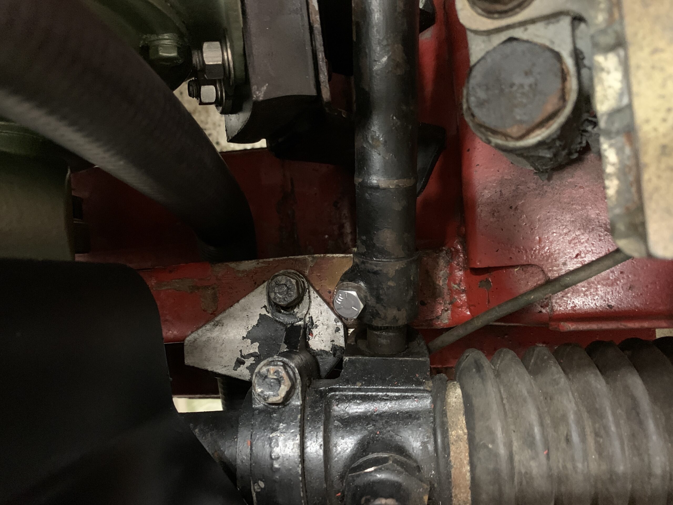
New Steering Column to Rack Bolt Installed
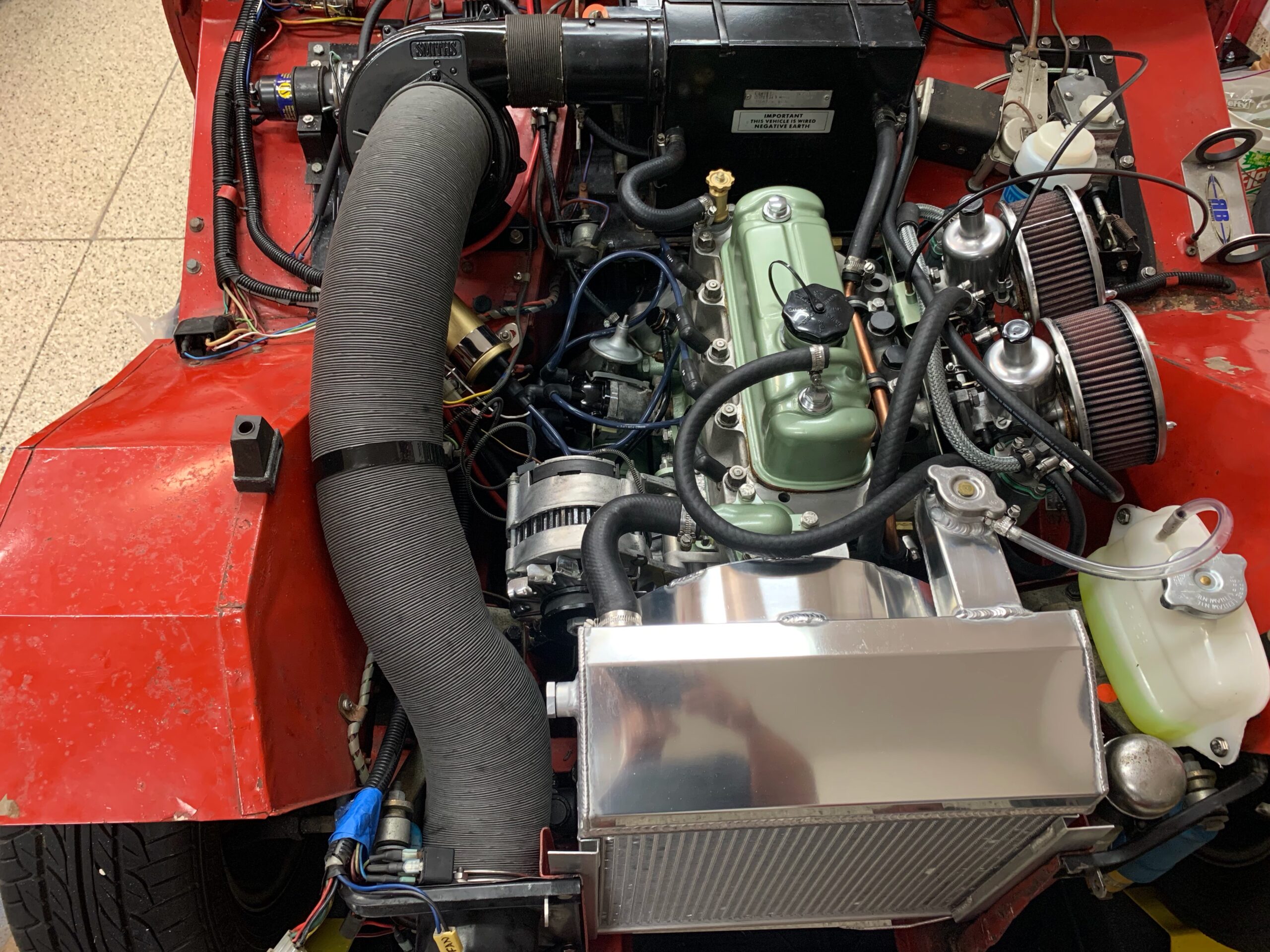
Reinstalling the Engine and Gearbox and Starting the Car
Following a couple of months of engine and gearbox refurbishment, it was time to reinstall both into the car and try to start the car. This is a short, but probably incomplete list of items to check to complete the installation process:
-
- Tighten Motor Mounts
- Connect alternator wires
- Connect distributor to the coil.
- Connect distributor crane ignition wires to the crane module.
- Add oil to engine. Half fill the oil filter with oil and tighten.
- Add oil to transmission.
- Connect radiator hoses and copper pipe.
- Add coolant
- Install rocker cover
- Bleed the clutch slave cylinder
- Connect speedometer cable to transmission.
- Connect heater hose from cylinder head valve to heater
- Ground strap to engine.
- Install capillary line temp sensor to the cylinder head
- Connect oil pressure gauge pipe to fitting on the RH side of engine block
- Connect the starter cable to the solenoid
- Install manifolds, heat shield, carbs, copper pipe, carb springs, fuel hose between carbs
- Put oil in the carb pistons
- Connect choke cable
- Install air filters with new gaskets
- Connect the breather hose to the PCV valve on the intake.
Engine Start Up Problems
After the engine and gearbox were installed we thought we were ready to fire her up and go for a drive. Unfortunately, the engine ran very rough and would not idle. so we began a process of troubleshooting the problem beginning with ignition.
The timing mark on the crankshaft pulley is actually on the inside of the belt making it extremely difficult to read from the front of the car. One almost has to get under the car to see the little mark. To make this process easier, a mark was painted on the outside of the pulley consistent with the inside mark.
Timing mark on crank pulley
So to begin to address this I first need to get the number one piston in the compression stroke to find top dead center. To do this I used my whistle attachment to the spark plug hole on the number one cylinder. I put the car in fifth gear and pulled it forward until the whistle sounded this told me that I was on the compression stroke of the first cylinder. I stopped movement of the car as soon as I heard the whistle figuring that the timing mark on the crankshaft pulley was now approaching the pointers on the timing chain cover. I got under the car and checked where the timing mark was on the crankshaft pulley and then got up and pulled the car ever so slightly forward again. I repeated this procedure until the timing mark on the crankshaft pulley was aligned with approximately 7° on the pointer.
I then took the distributor cap off of the distributor to observe where the rotor was pointing. It was pointing to the number one terminal in the distributor cap as it should. I put a line on the Distributor body to align with the center of the rotor pointer.
The next step was to address the optical sensor in the distributor. The ignition of the car was switched on being careful not to engage the starter and crank the engine. The screw holding the optical trigger was loosened and rotated in a clockwise direction very slowly until the red LED on the crane ignition module lit. This signaled that the spark would be sent to the first cylinder ignition terminal in the distributor cap at exactly the right moment.
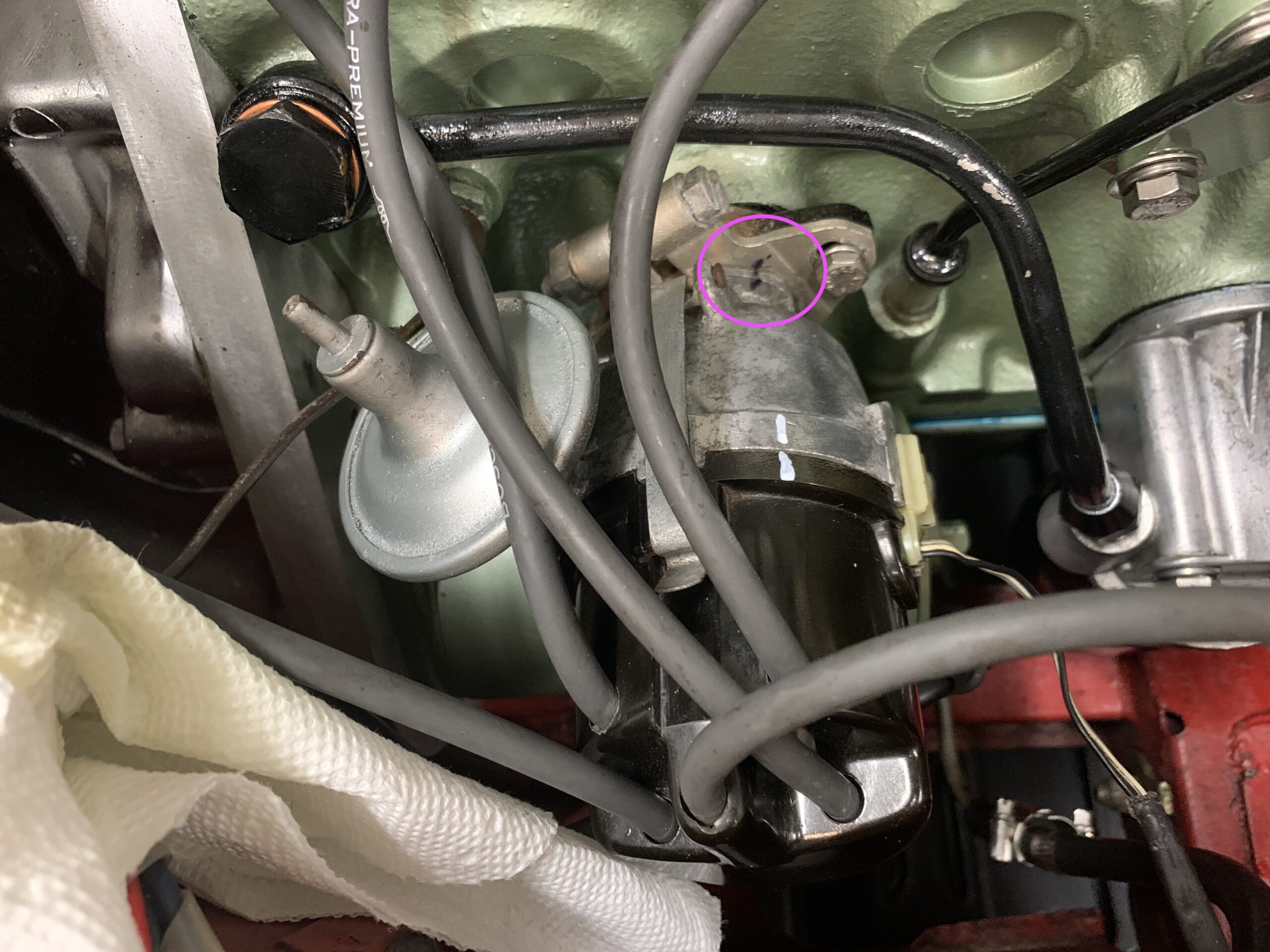
The engine started again but just barely so it was time to explore the distributor and ignition a bit more. The distributor was removed from the engine and the coil cable was disconnected. The distributor could then be held flat in one’s lap to try to adjust the swingarm on the electronic trigger. The 20+ year old wire that connects to the trigger is so brittle that it moves the trigger whenever it moves. Making final adjustment quite difficult. Add to that that the nylon fastener on the side of the distributor is broken and this allows for quite a bit of movement. This may be creating a problem for us. The nice thing about having the distributor in one’s lap to look at was that the optical trigger could be adjusted and the LED light could be seen as it came on. One could also hear the spark at the coil since the cable was not connected.
The oil line that goes to the oil pressure gauge is actually rusted through or broken and it is leaking oil on the battery tray and then down to the floor. There’s no way to fix this and it will have to be replaced.
Just to make sure we were getting fuel, the hose from the carburetor was disconnected and put it in the gasoline can and then the fuel pump was turned on. There was plenty of fuel getting to the carburetors.
A little oil residue was noticed on the right side of the engine block. I loosened and retightened each of the nine cylinder head nuts in the order specified in the workshop manual. Torqued to 50 lbs which is the specification for studs with dimples in them. This seemed to have fixed this issue.
The engine still won’t run properly. I am now thinking that the culprit may be the Crane XR700 trigger and wiring. It was not installed properly and the wire is now so stiff that it moves the optical trigger inside the distributor. Crane doesn’t exist anymore. They were bought by FAST.
The wires should be tied down with a small zip tie provided in the kit and they should be in a rubber sheath exiting through a hole in the nylon fitting on the side of the distributor. Apparently when the unit was installed the zip tie and rubber sheath were omitted and to make installation easier, the nylon fitting was simply cut. All of this results in the wire being quite loose.
Crane XR700 Distributor Wiring
Just to eliminate the possibility of a faulty rotor I replaced the rotor in the distributor with a new “high quality” rotor from Moss Motors. This did not solve our problem, but one more possible cause was eliminated.
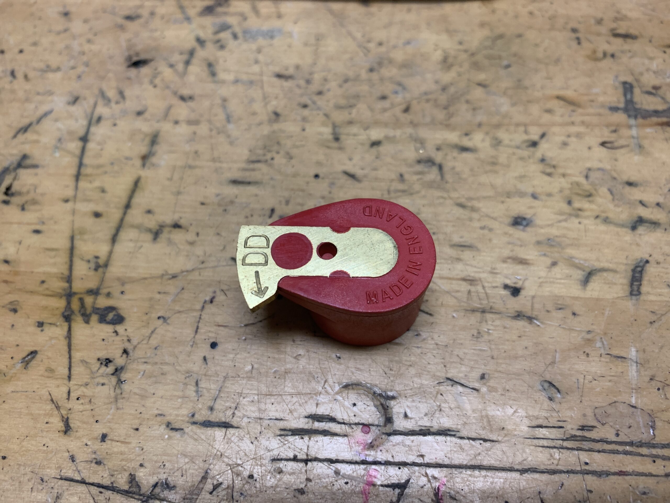
New Moss Motors Rotor
The new rotor installed and pointing to the #1 cylinder ignition wire on the distributor cap.
New Rotor Installed in correct position
Just to eliminate another possible trouble maker, The distributor cap and the ignition wires were replaced with new items also.
It was noted previously that the copper oil pipe from the gauge to the engine was cracked and leaking. We ordered a new replacement part from Bugeye Guy and installed it. Another problem solved.

Oil Pressure Gauge Copper Pipe Replaced

New Oil Pressure Pipe Fitted

New Oil Pressure Pipe Fitted
We decided to move on to adjusting the Carburetters. The air cleaners were removed and the engine was run to get it up to operating temperature. Then the dashpots were removed.
Carb Adjustment
The following procedure was then followed:
Loosen linkages
Back off throttle adjustment screw then turn down 1 to 1 1/2 turns. I initially turned down one full turn
Turn jet adjustment screw up (17mm wrench) until the jet is level with the bridge.
Check that jet is centered by reinstalling the piston and dash pot and dropping the piston. You want a nice clunking sound.
Turn the jet adjustment screws two full turns down. (I did 2 1/2 turns or .71”)
Listen with a hose or use a unisyn to equalize air flow on the two carbs. Adjust the throttle adjustment screws until proper idle speed is obtained (550-1,000). Listen again until carbs are the same.
Then check richness. Lift pistons slightly. If stalls then too lean. Turn jet adjustment screw one flat at a time. Blip throttle after each adjustment. Lift piston again. You want it to speed up a little and then settle back to idle – not stall.
Adjust the choke cable so that there is 1/16” free play before the arm starts to move.
Turn the fast idle adjustment screw so that it barely touches the cam then adjust to about 1,000 rpm
We were able to synchronize the carbs successfully and the the engine now starts easily and idles nicely. It was time to try to drive the car under load and see how the engine behaved. The test drive was successful and while the engine seems to run smoother than it has in a long time, it does not seem to have the responsiveness that it used to have. Our thinking is that we need to check the ignition timing for maximum advance. However, it is time to get the car home to Delray Beach, so we will have to wait on the timing.
Much was accomplished in the last few months but the braking modifications and final engine tuning remain before we can say “job well done.” Perhaps after the New Year, I will get the car back to Dad’s for these last steps.

Test Drive