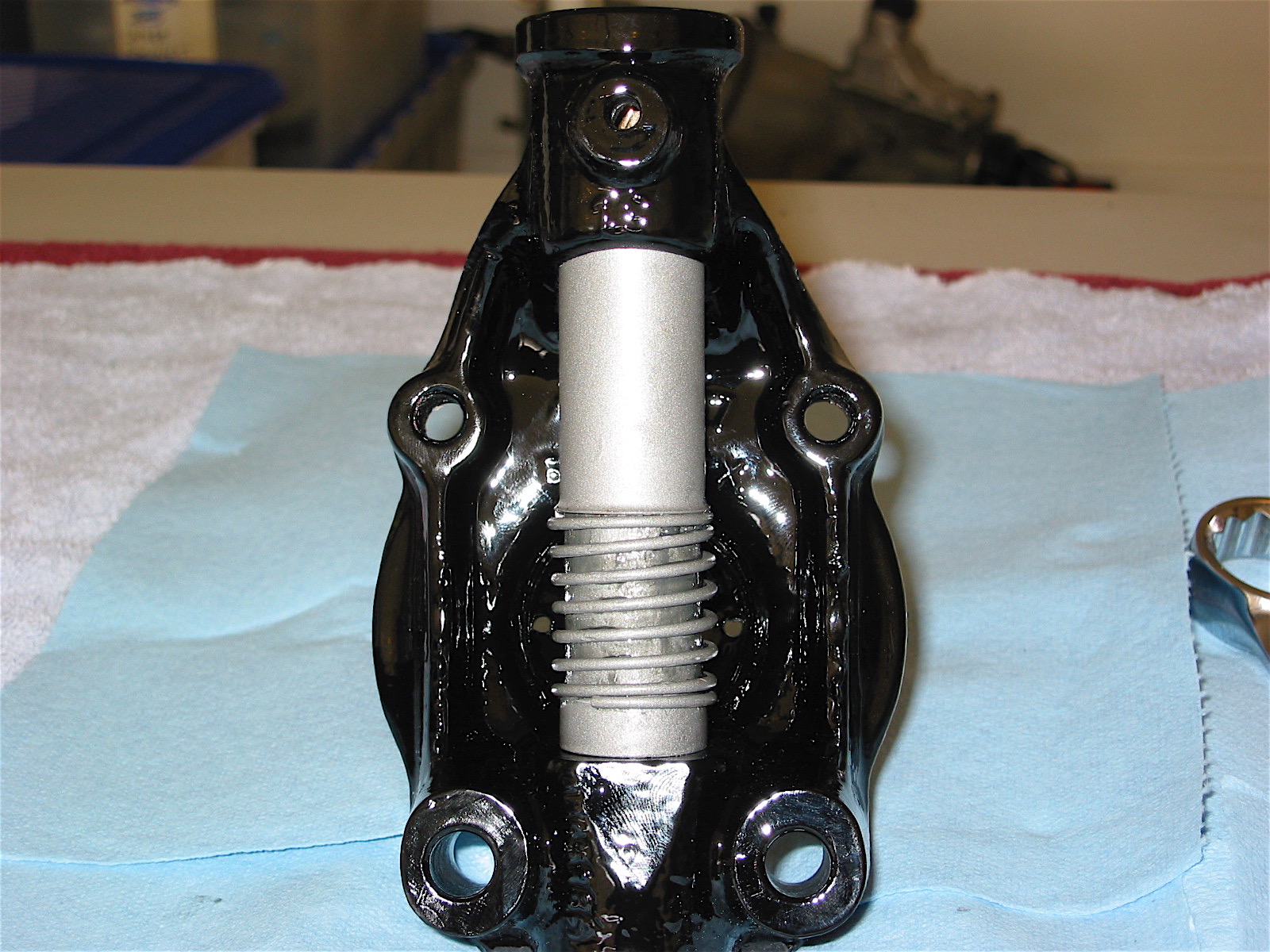
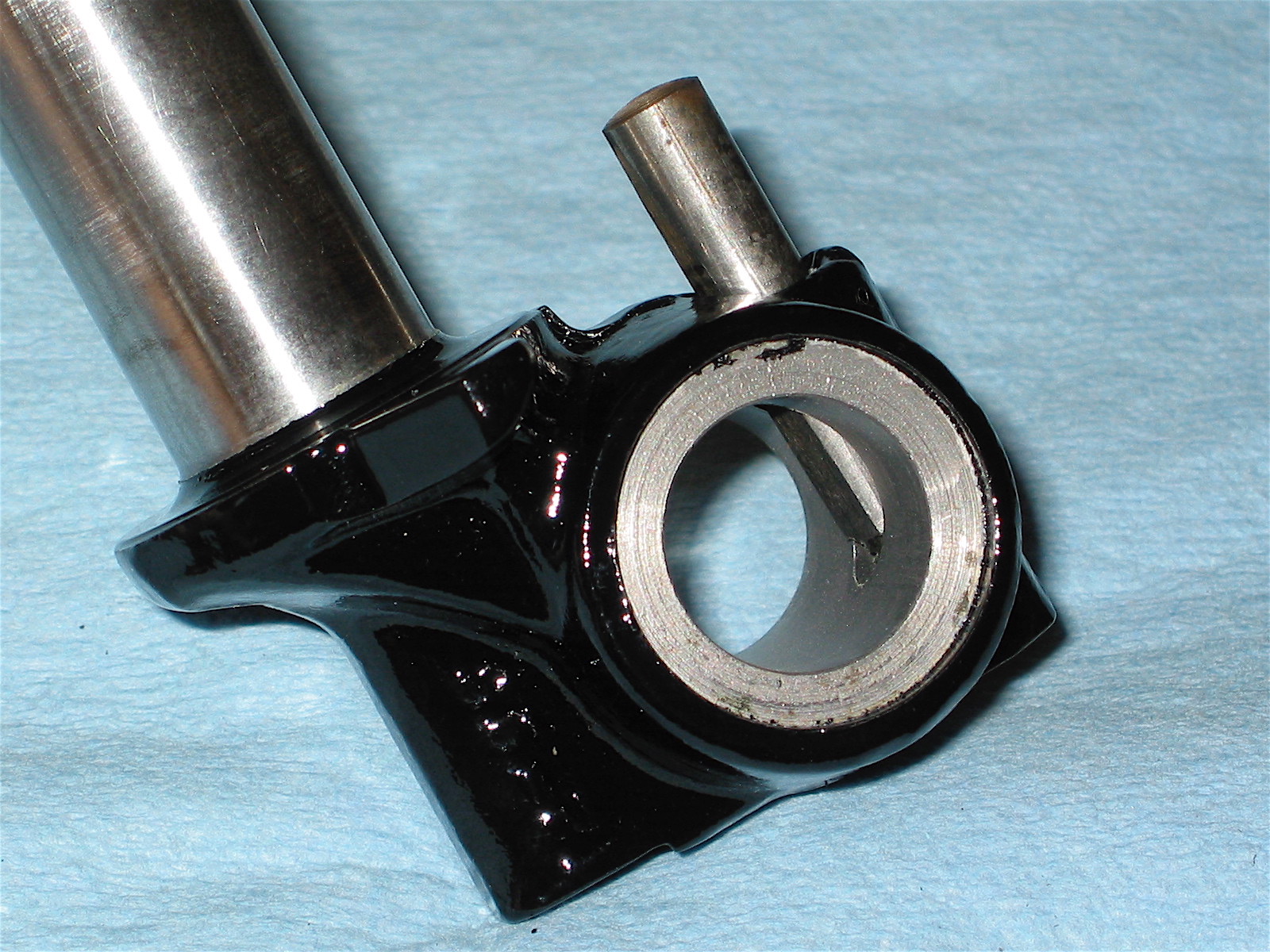
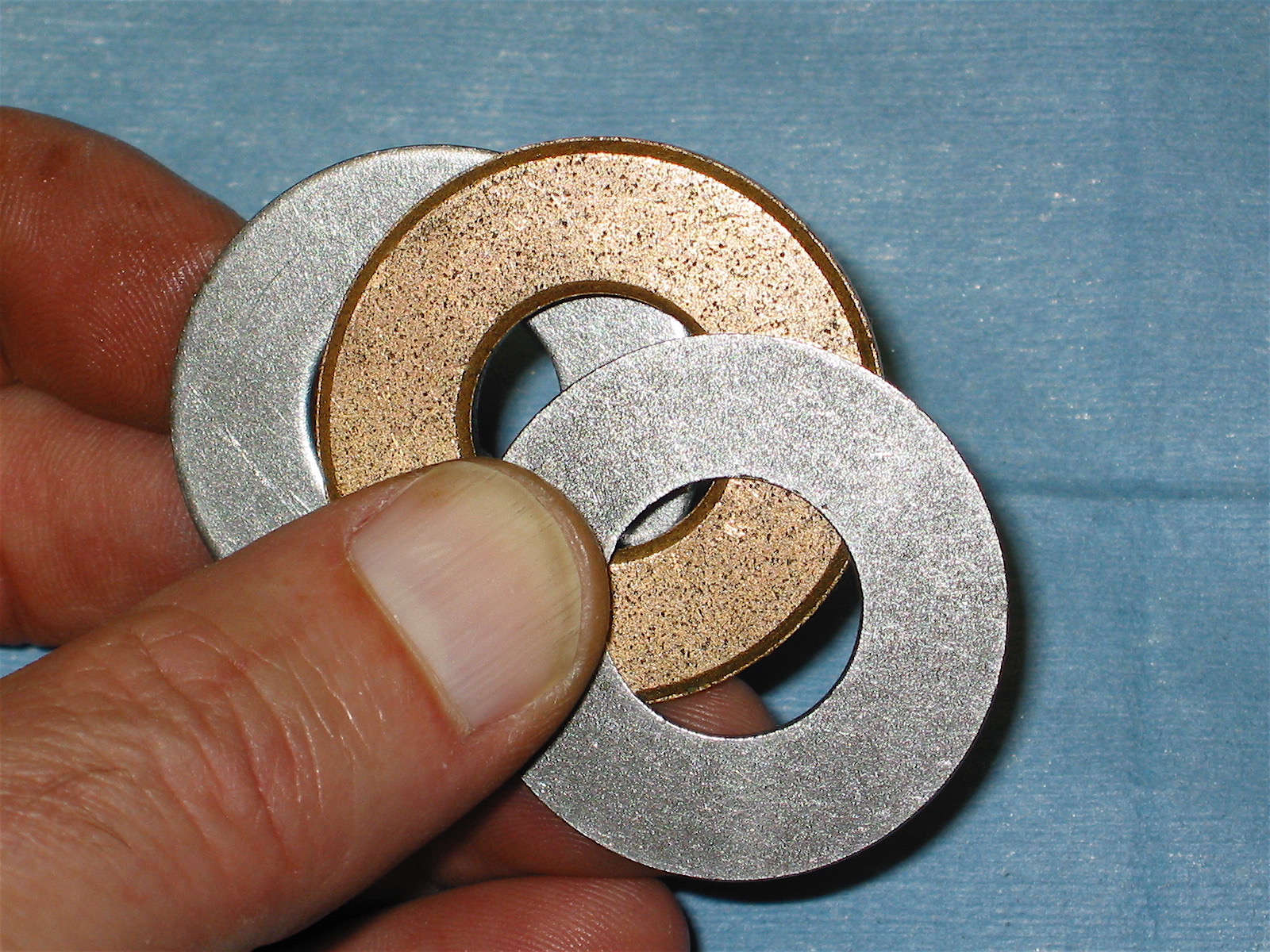
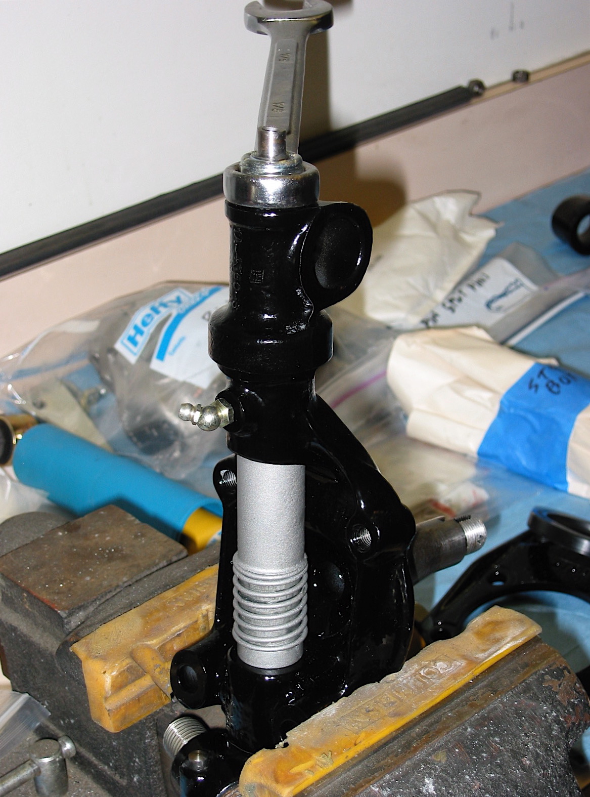
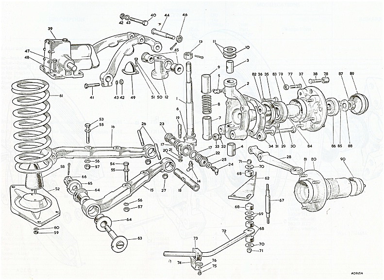
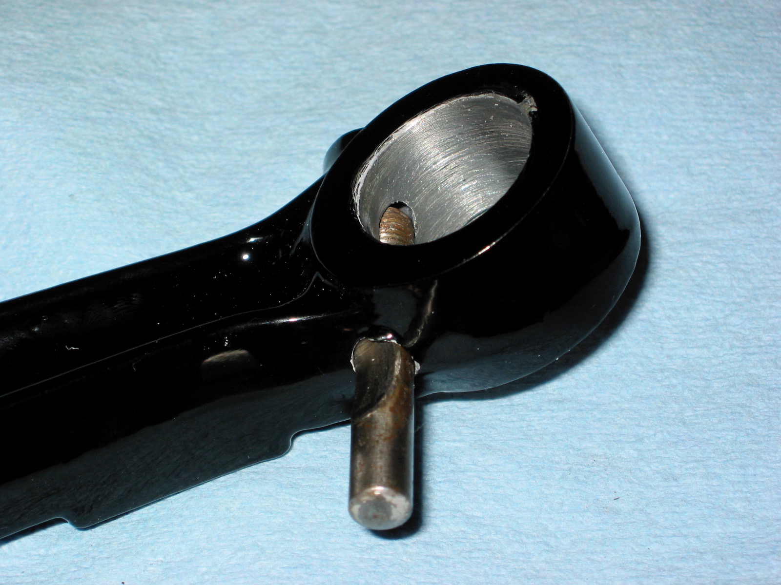
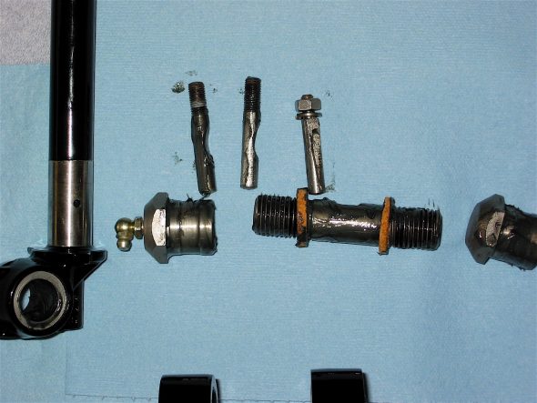
The New Year itself began with attention turning to the front suspension of the Bloody Beast. The first step was the assembly of the swivel axles. Bruce Phillips at Healey Surgeons rebushed and reamed the axles for me and supplied new swivel or “king” pins. I then applied a light coating of moly to the pin itself and slid the cork washer, with the chamfered edge down, onto the pin. The swivel pin can then be inserted into the axle and three thrust washers are applied to the top of the pin. One “oilite washer” is sandwiched between two “staybright” washers. The oilite washer was first soaked overnight in motor oil. The top trunnion was then placed over the top of the swivel pin and tightened down with a nylock nut. .002” is the maximum permissible lift.
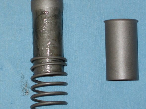
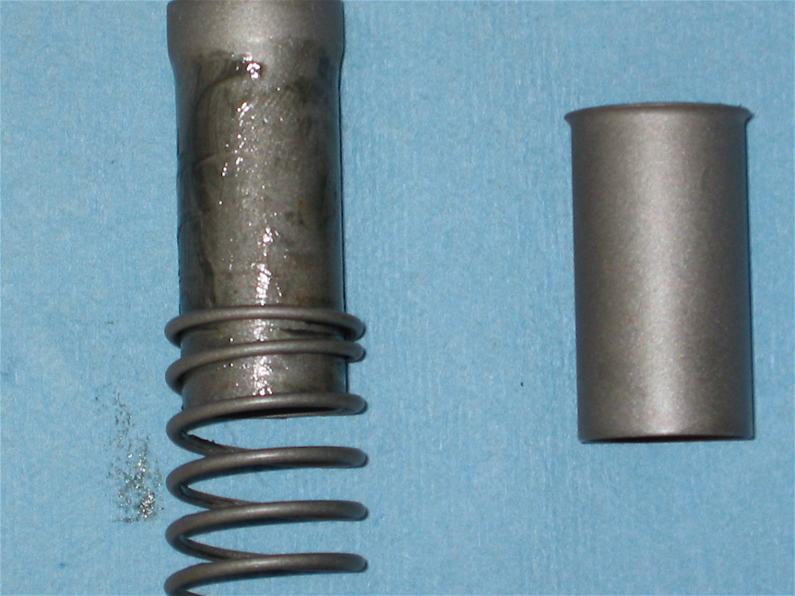
Swivel Pin Spring
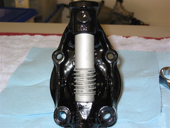
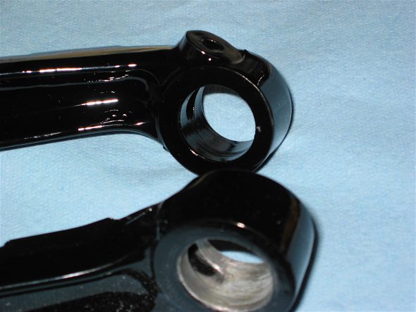
Swivel Axle
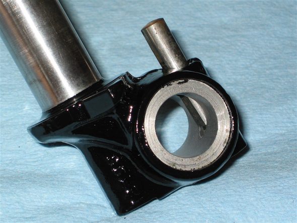
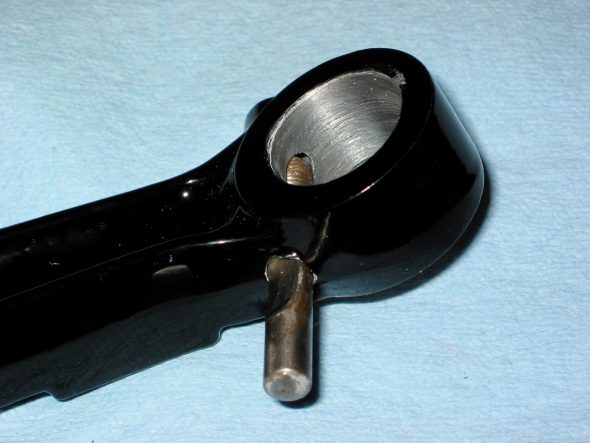
Swivel Pin lower trunnion

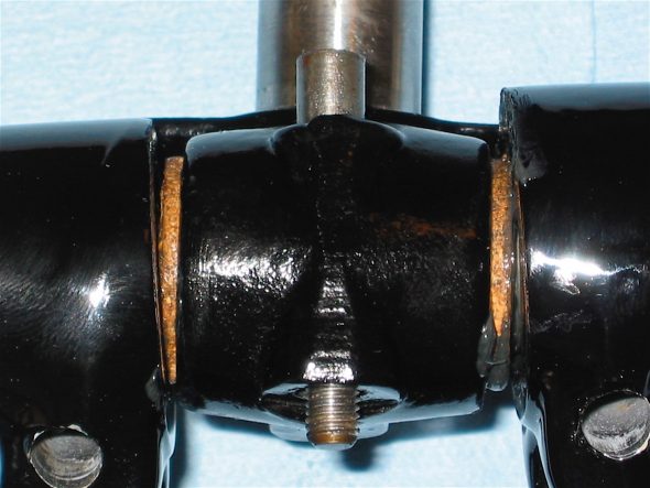
Upper Trunnion washers 3
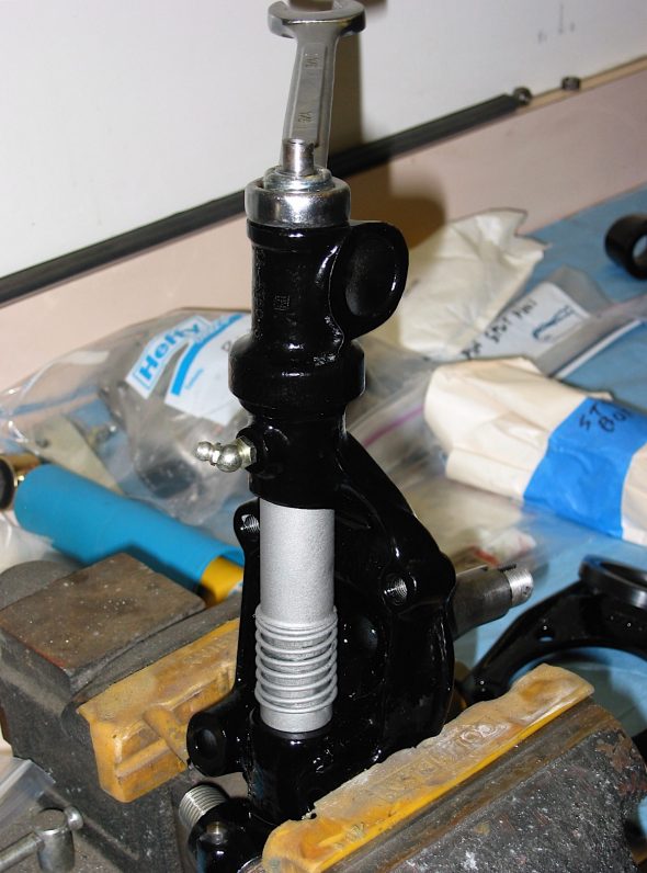
Upper Trunnion tightening
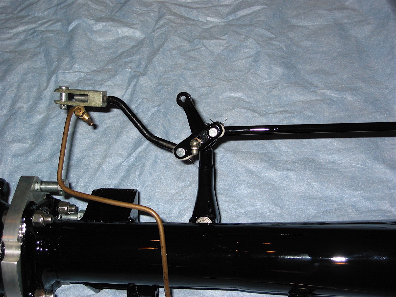
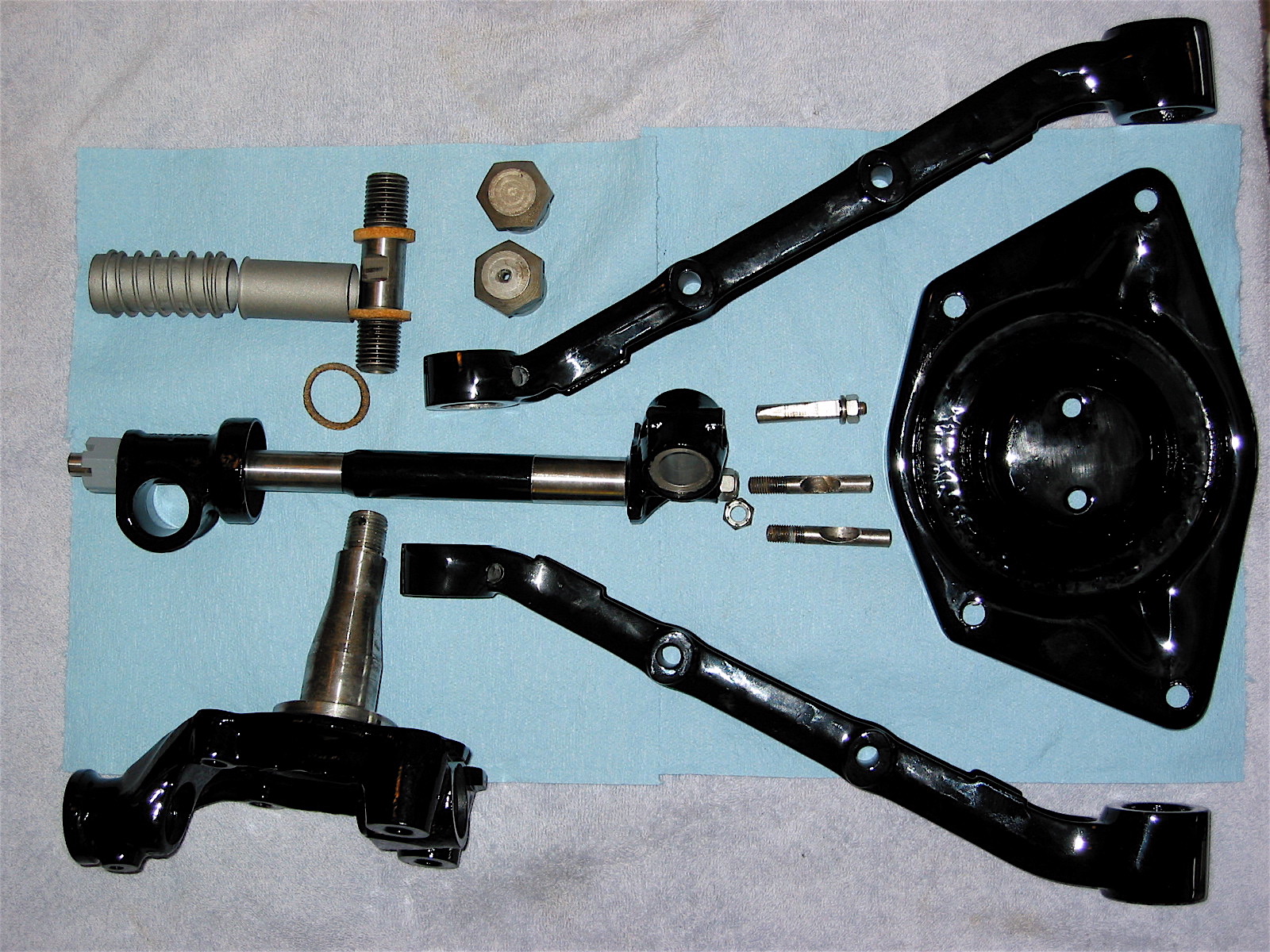
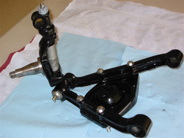
I then collected the components needed to assemble the swivel axles to the frame. These included two paired control arms, the assembled swivel axle, the control arm and upper trunnion bushings, the necessary cotter pins, the shock damper, the lower trunnion bushings, cork seals and the lower link fulcrum pin.

Front Suspension Assembly 2
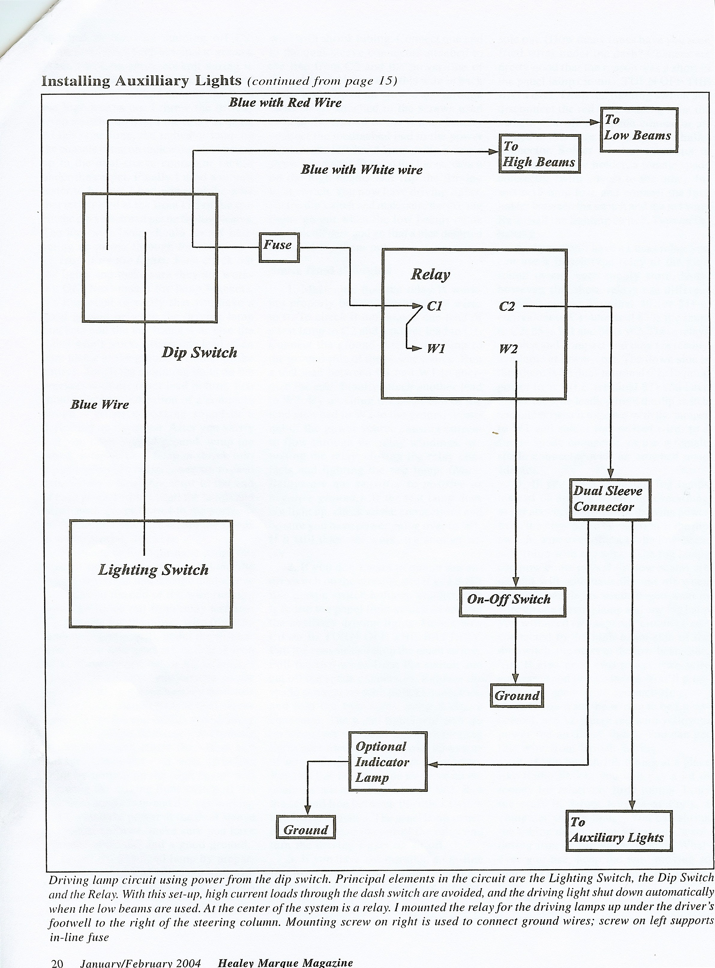
The factory workshop manual provides a very helpful illustration of the components and their relationship to each other.
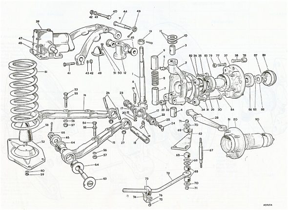
Front Suspension Schematic
I had paint inside the journals of the control arms and the shock dampers, as well as the holes for the cotter pins so it was first necessary to clean these areas so the paint would not restrict access.
Control Arm Paint
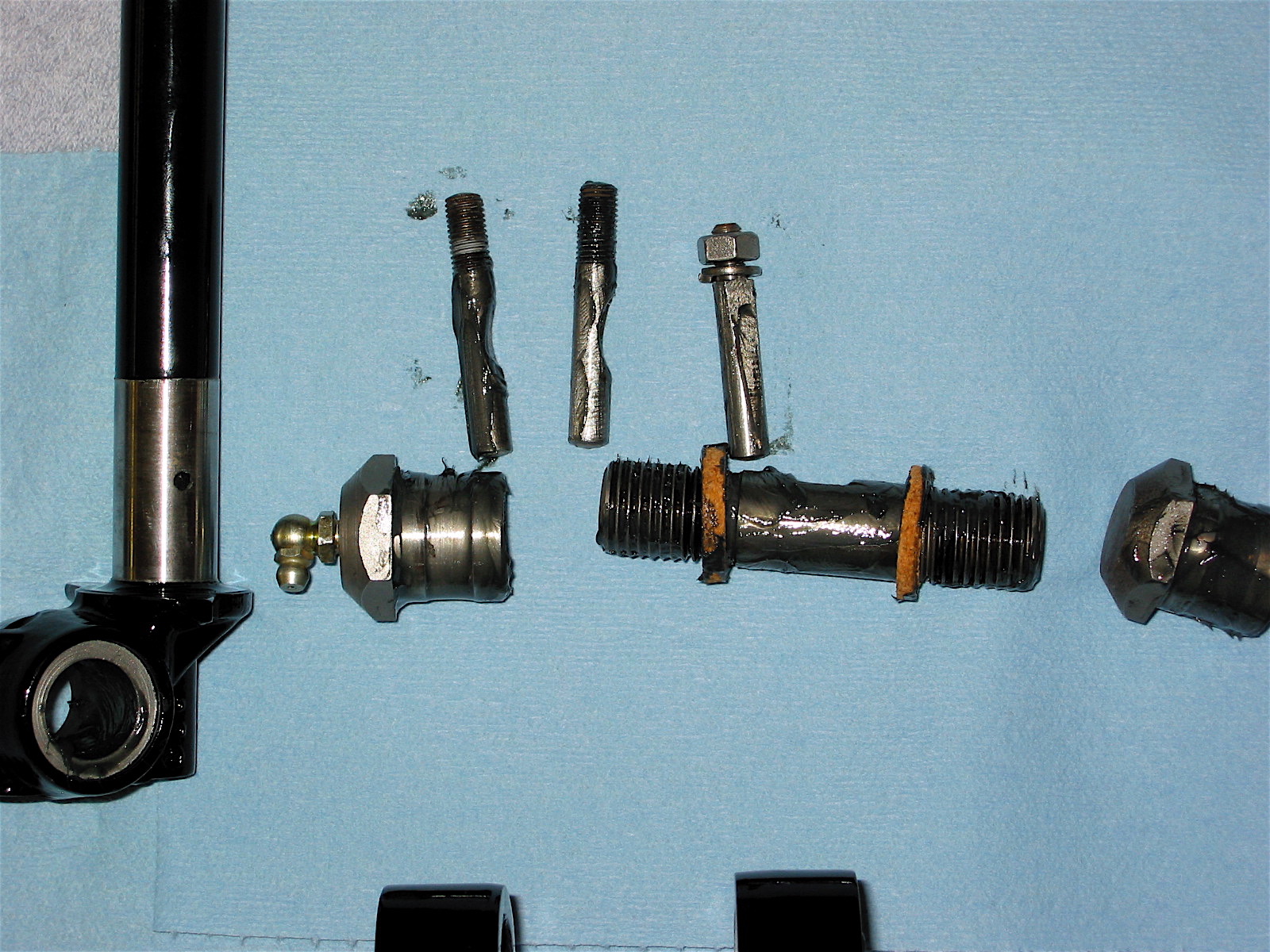
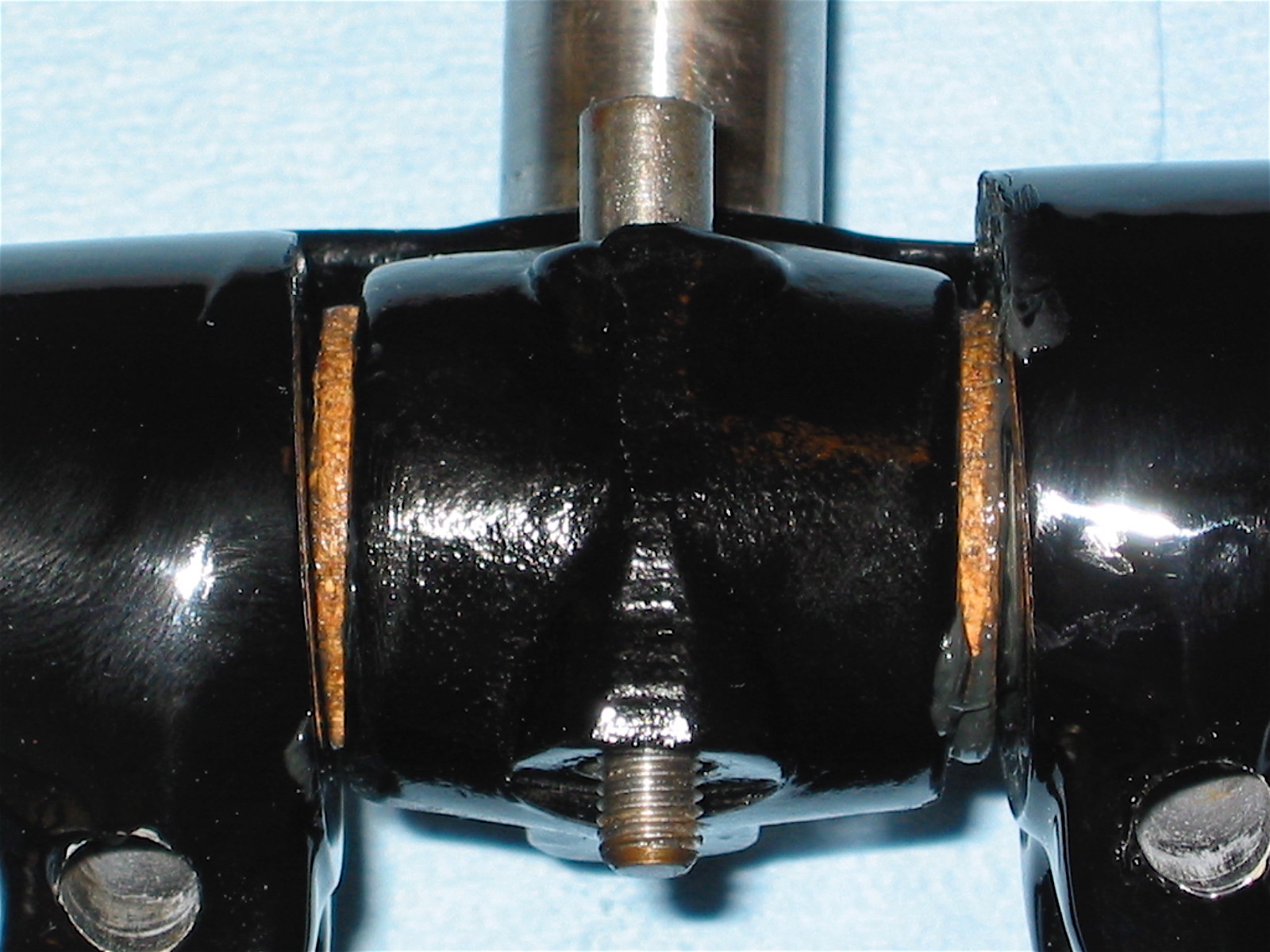
To assemble, I had the side of the control arms with the flats for the cotter pin nuts facing down. I then fastened the spring plate to the control arms so that the alignment of the assembly would be correct. The grease fittings on the lower trunnion bushes face the front of the car. The cotter nuts should be tight but not so tight as to risk distortion of the bushes. The bushes are tightened to the control arms and then backed off a flat. A .002 feeler should be able to be inserted between the face of the bushing and the control arm.
Control Arm Cotter Pins
Lower trunnion components
Lower trunnion in place 2
Front Suspension Asembly 1
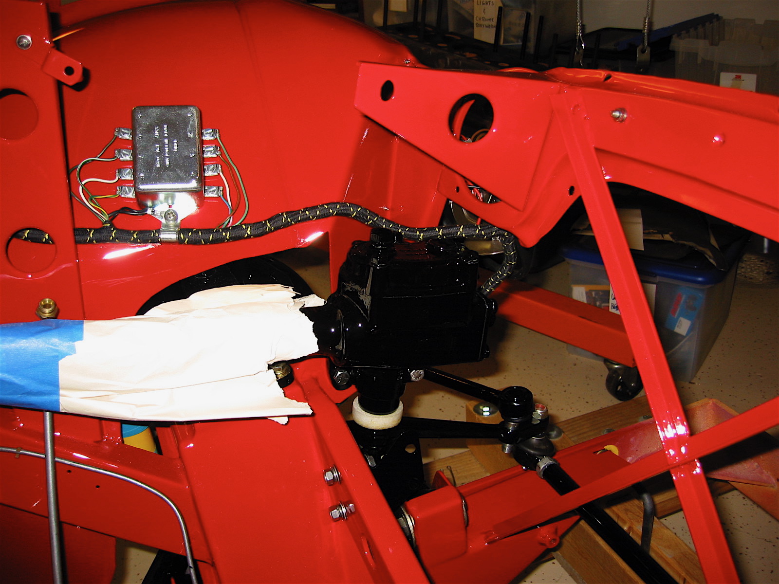
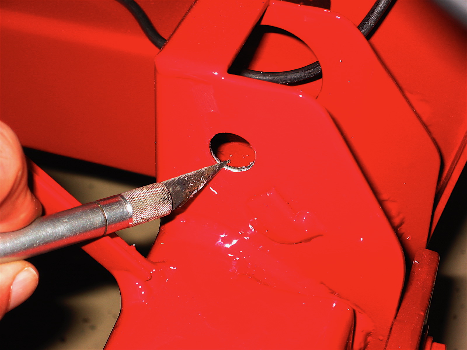
Then the time came to secure the swivel axle assembly to the car. Again, the first step was to remove paint from the frame openings that received the pins.

Cleaning hole for pin
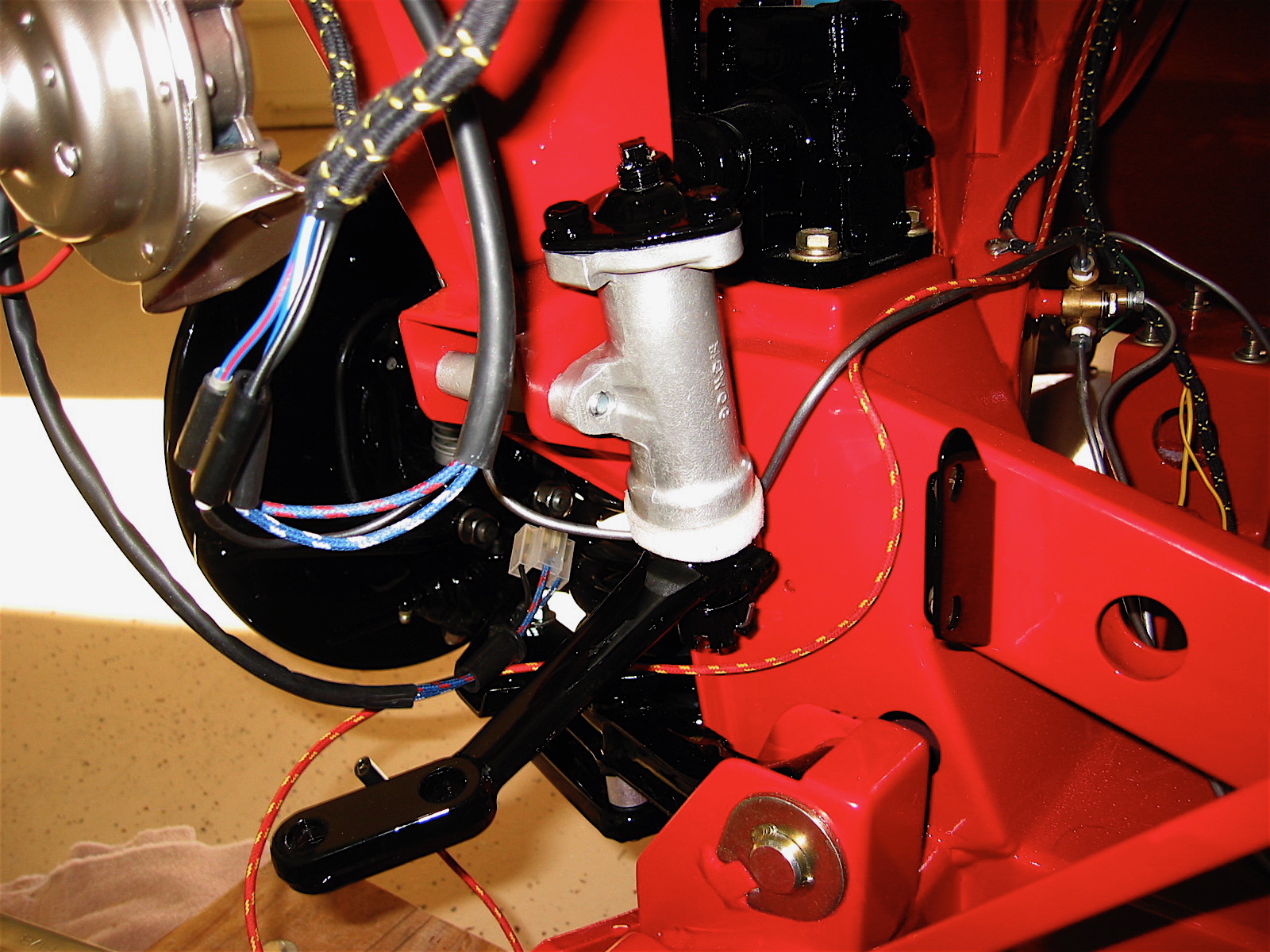
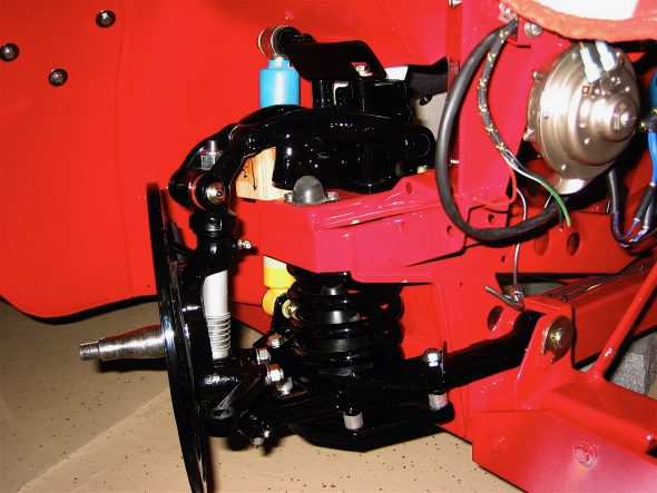
Next the small shock rubber bumpers were screwed onto the shock mounting plate. The shock damper sans its valve was fastened to the frame, and Udo Putzke’s tube shock conversion upper bracket was also bolted in.
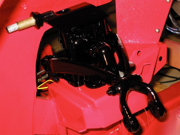
Front shock 7
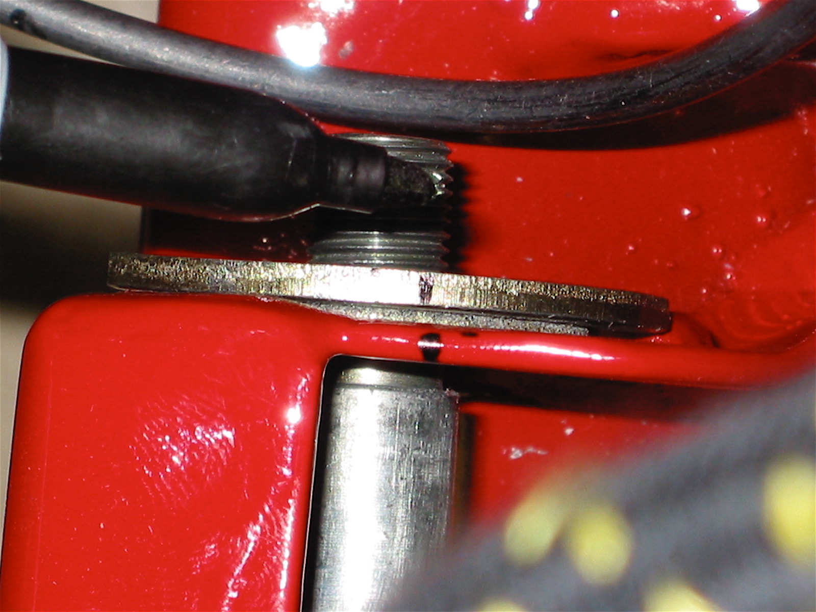
Getting the face plates of the lower fulcrum pin washers to line up can be a challenge, so before final assembly, I pressed them against the frame fitting and marked a line on the face plate and the frame to make alignment much easier later.

Marking pin placement
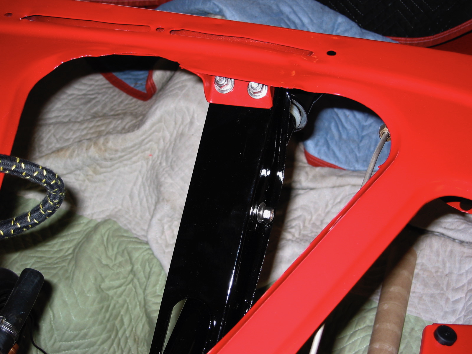
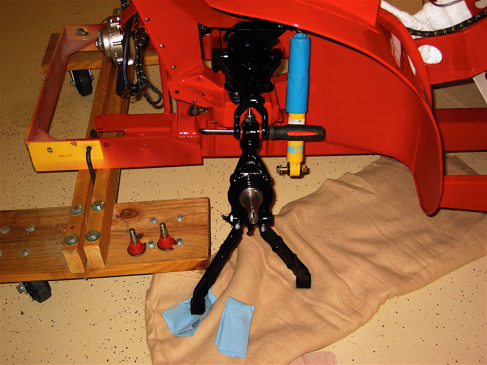
The poly bushings were then placed on the pins and the control arms were lifted up to the frame. A screwdriver was used in the upper link to support the weight of the assembly while it was positioned to secure.
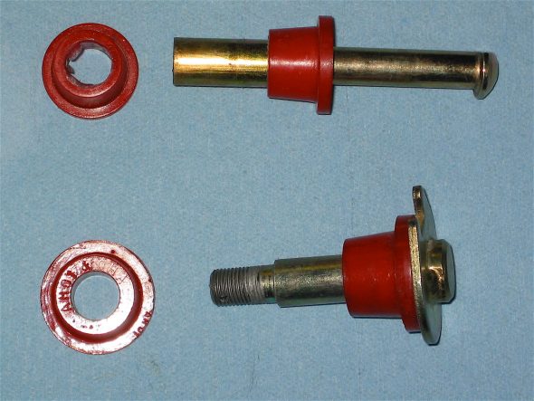
Front poly bushings
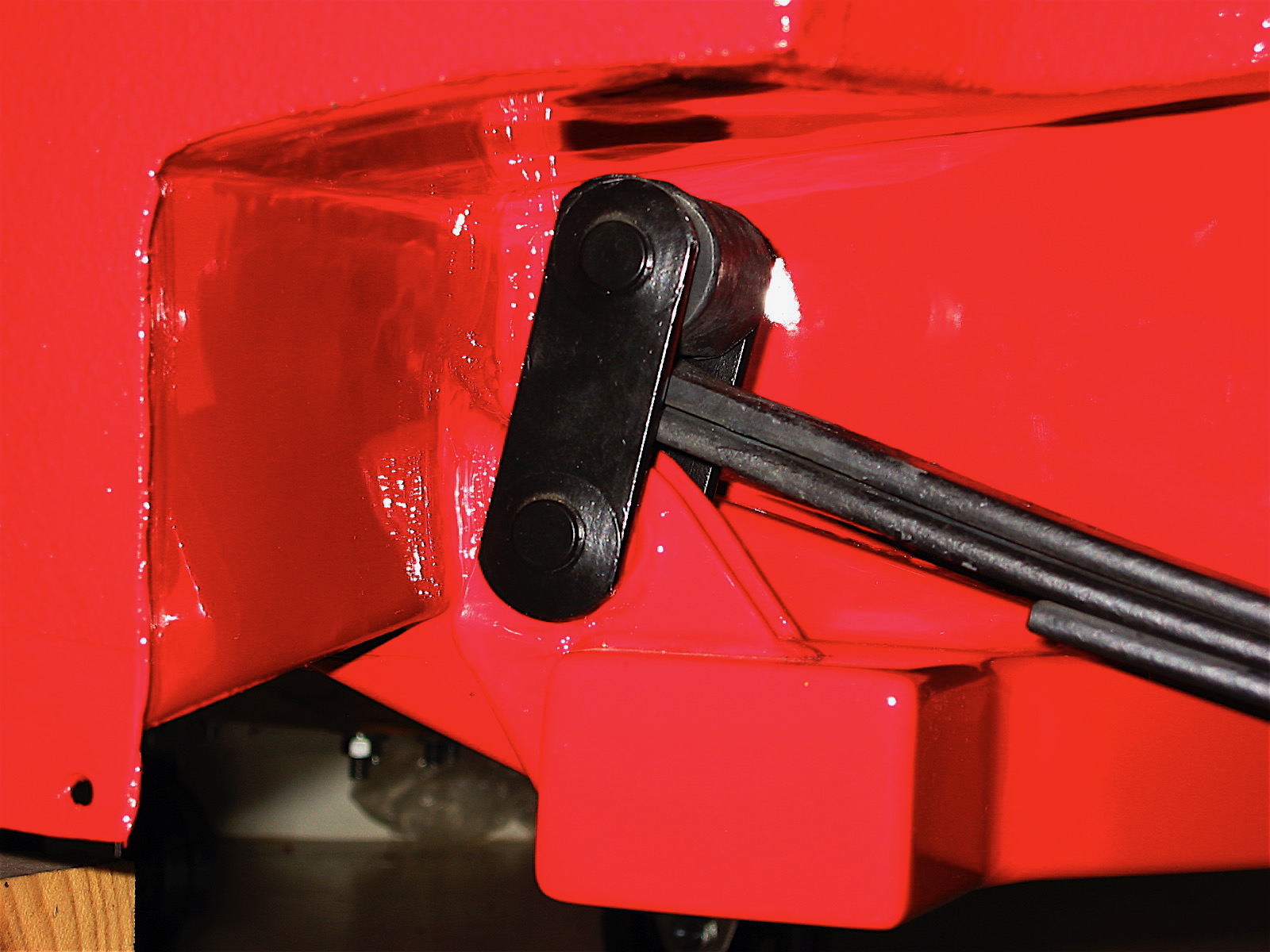
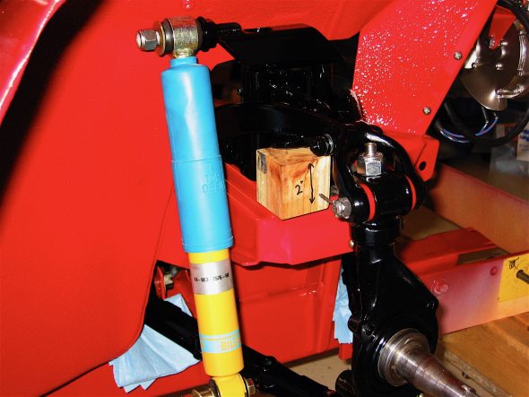
As per the workshop manual, a two inch block of wood was inserted under the lever shock to lift it to the proper ride height and then the shock and the lower fulcrum pins were tightened. A split pin was inserted into the hole through each fulcrum pin and bent back.

Temporary pin for shock
suspension spacer
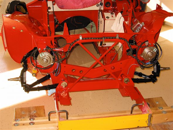
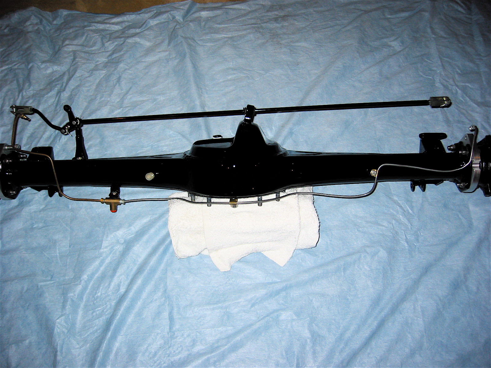
Installed axle assemblies
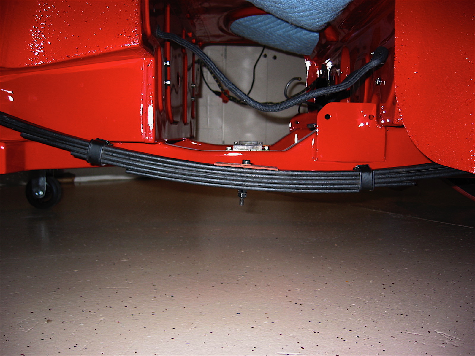
The next task was to install the spring plate and springs, the lowering spacers and bolts, the bilstein shocks, the disc brake dust shield and the caliper mounting bracket. These steps were complete for the left and right hand side of the car.
I used four pieces of 3/8” fine thread rod to help install the springs. The two rear rods were cut to about 7” lengths and the two front rods were about 5.” I also used long extension couplers and a flat washer on the rods below the spring plates to make it easy to access the nut with the wrench. A single regular nut would “hide” under the plate and be hard to get to. This arrangement worked well.
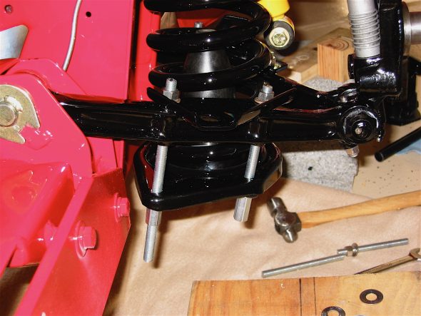
Installing coil springs
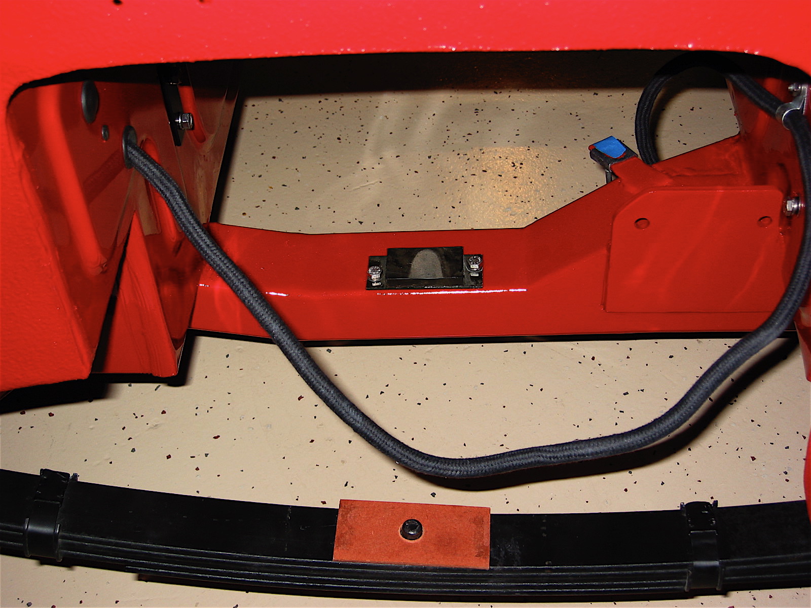
The spacers from Denis Welch were inserted between the spring plate and the control arm and the lower nuts were screwed up tight with the spring in place. Then one at a time the nut was taken off the top of the rod, the rod was tapped out of the hole through the control arm and spring plate and the longer than normal fastening bolt from the Welch lowering kit was installed.
Lowering Spacers 2
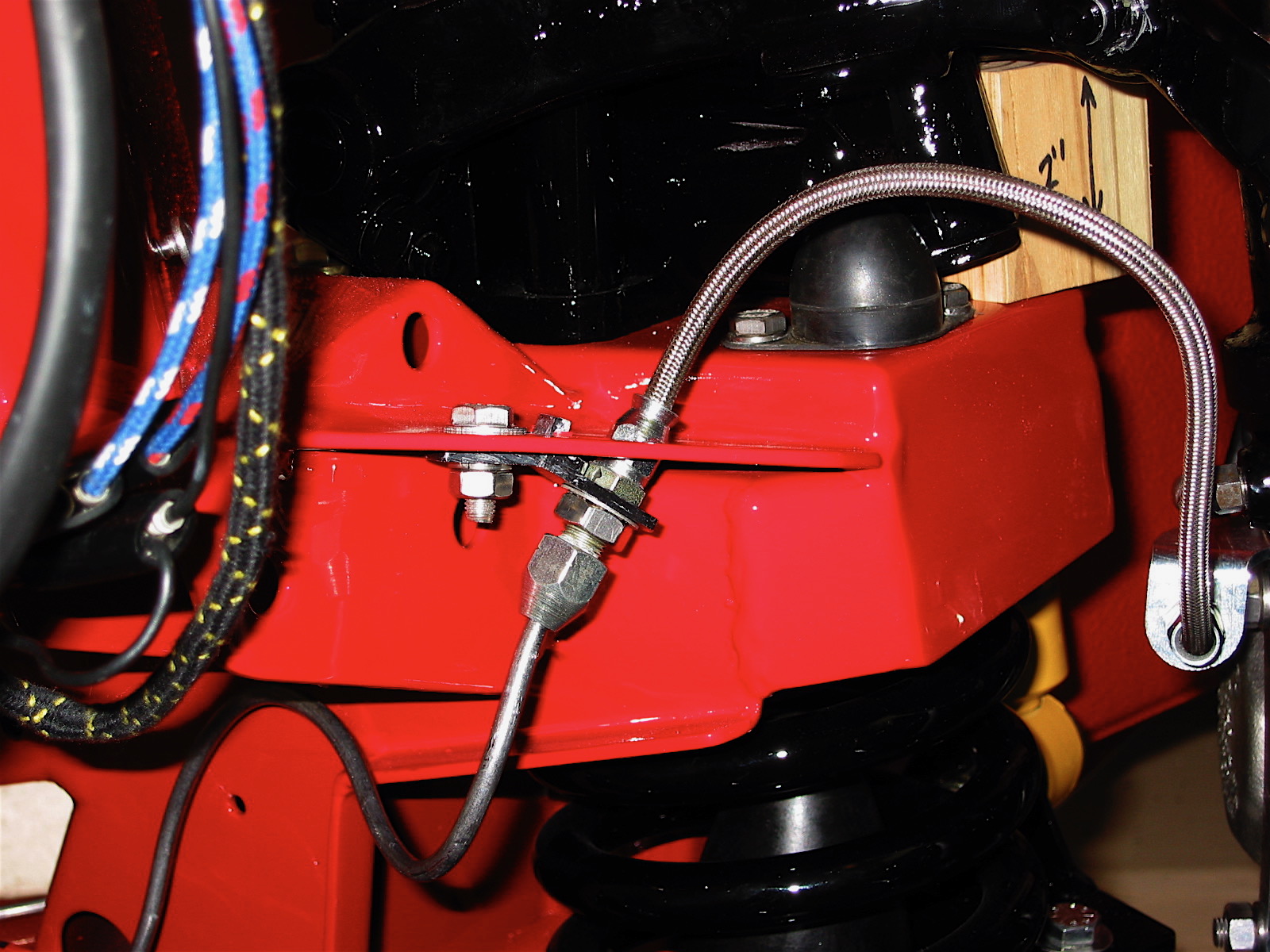
The Bilstein tube shock was then put in place and tightened with nylock nuts. This required lifting the shock with a bottle jack so that its bottom fixing hole would line up with the bracket on the control arm.
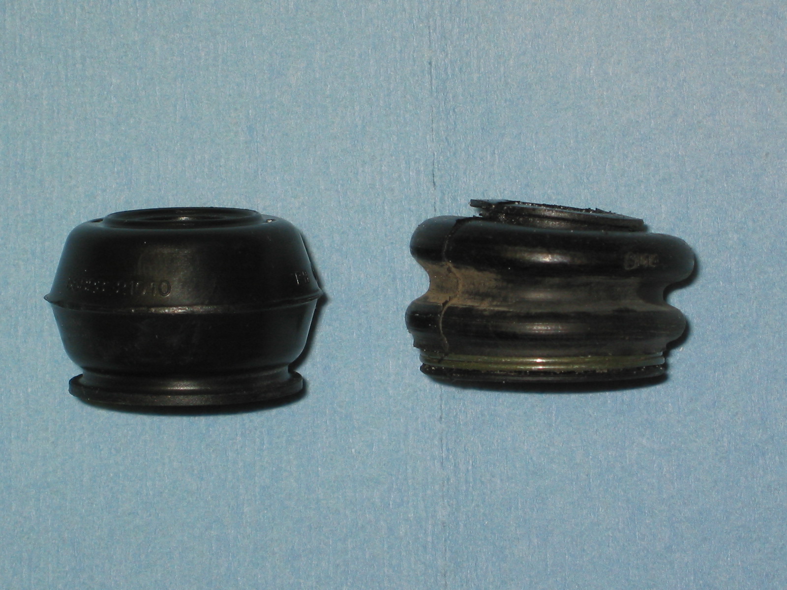
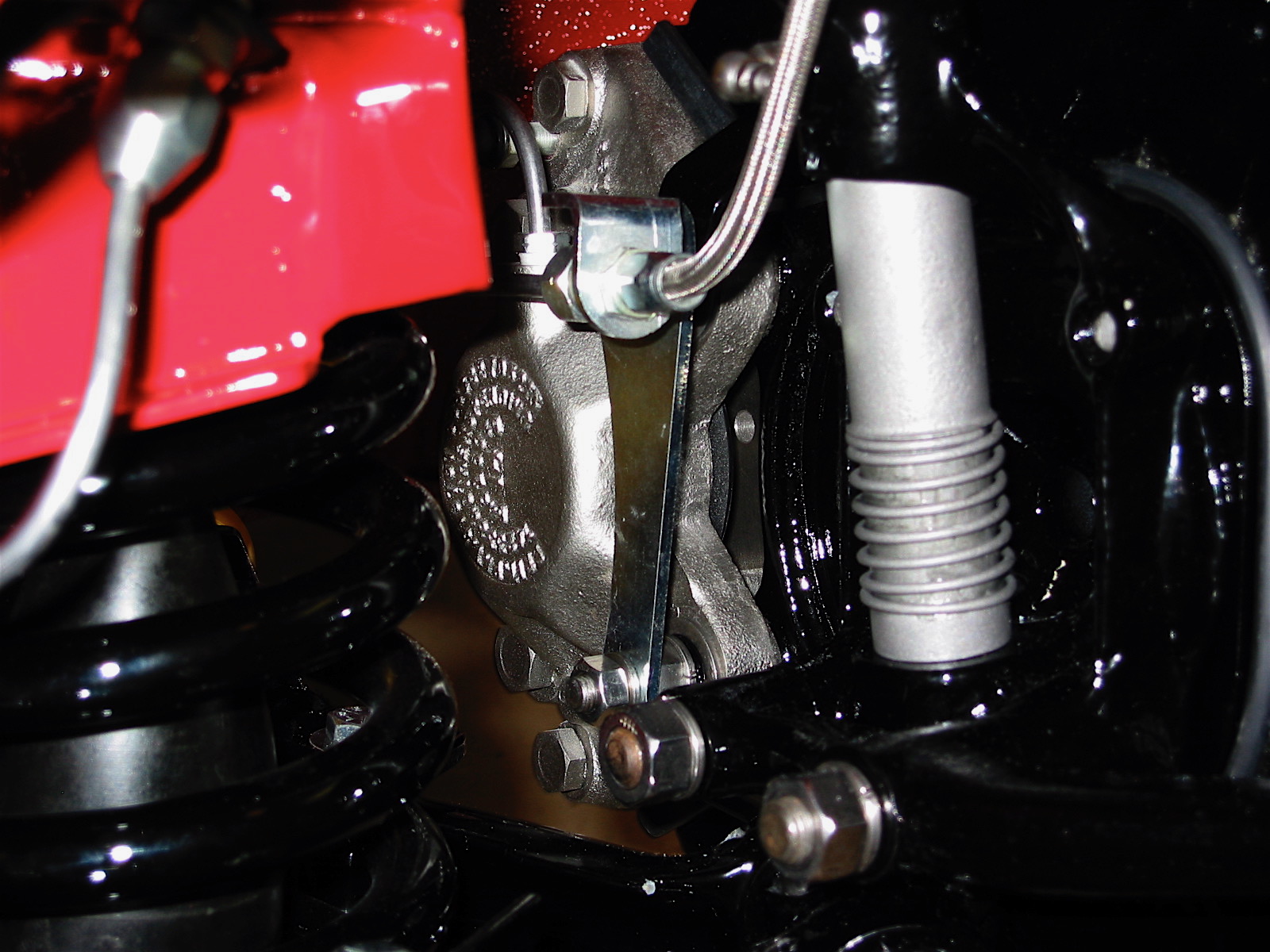
The rubber seals were then glued to the dust shield. I discovered that they probably did not need to be glued as they are a tight fit once the dust shield and the brake bracket come together. The steering arm, brake bracket and dust shield were then bolted to the swivel axle. A tab washer is used on the lower two bolts. The wood spacer block will remain in place until the wheels/tires are installed and the car is lowered to the ground.
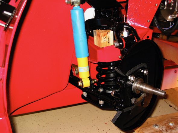
Dust shield installed