The Standard Steering Unit
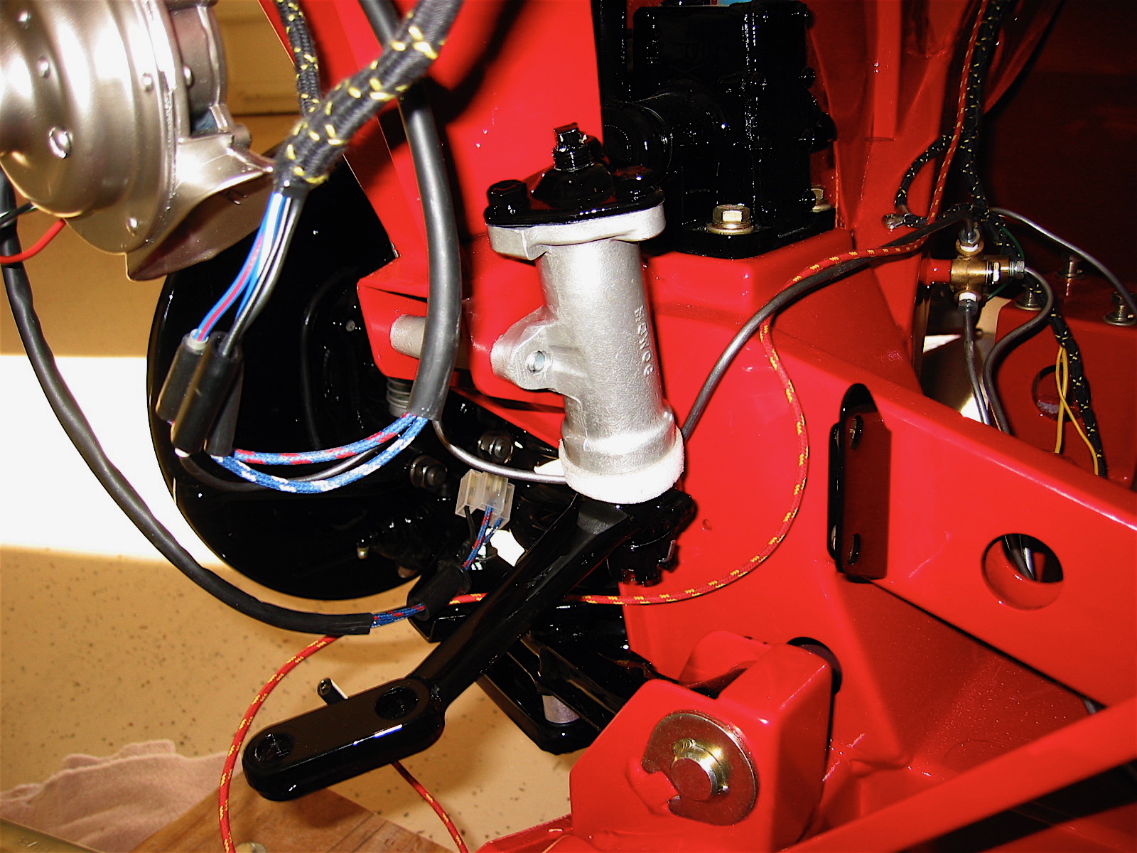
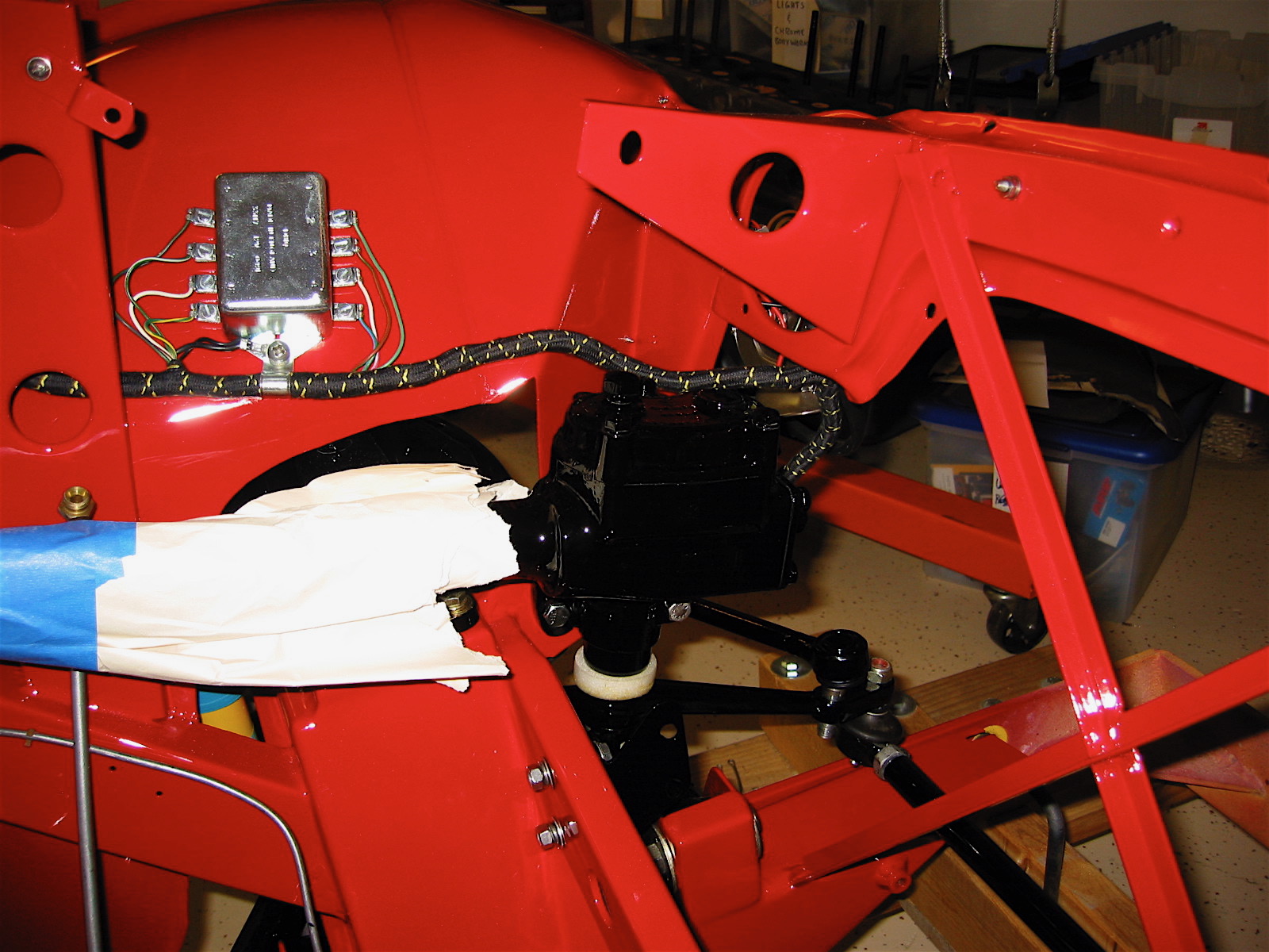
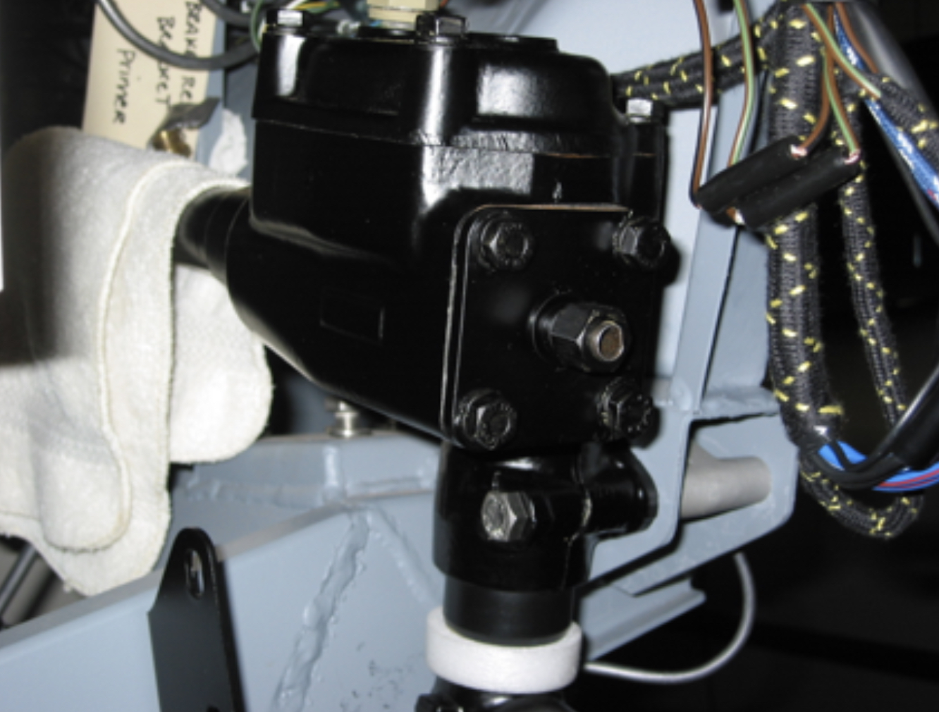
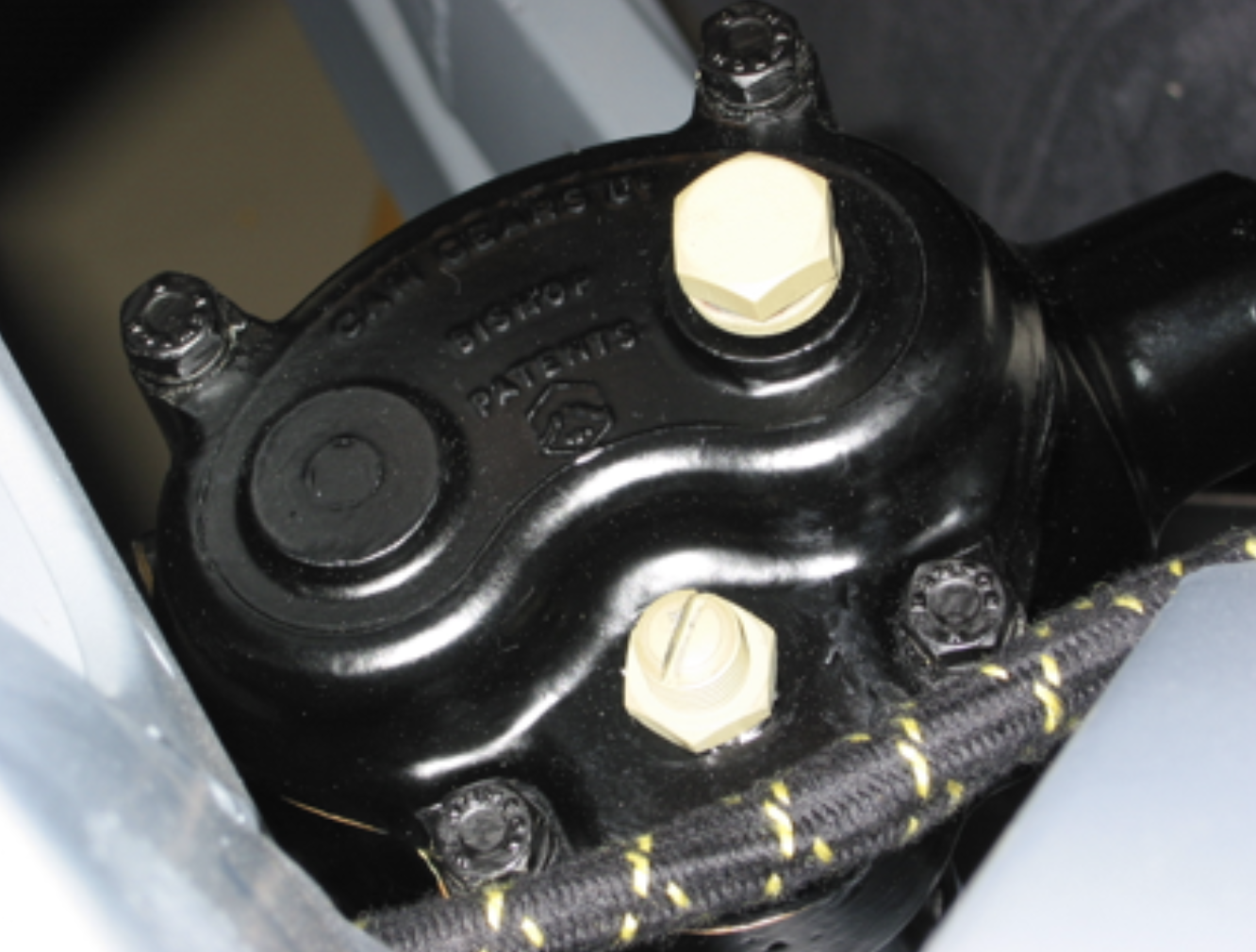
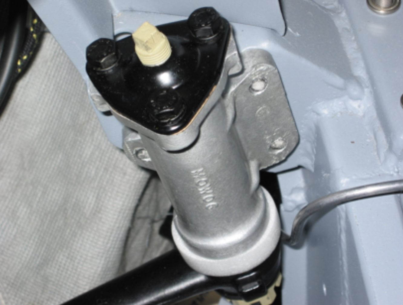
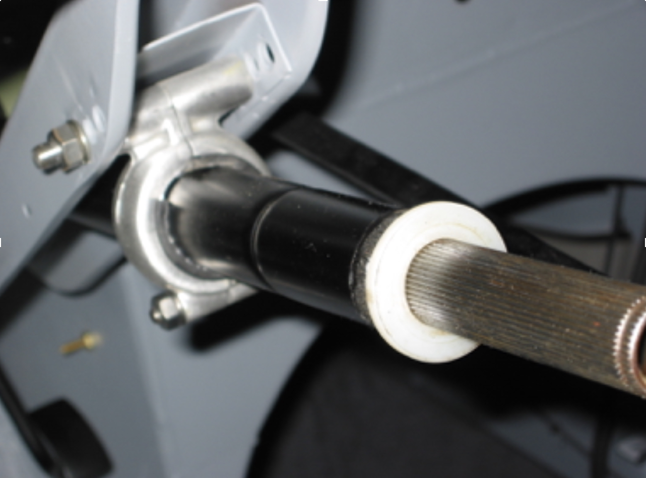
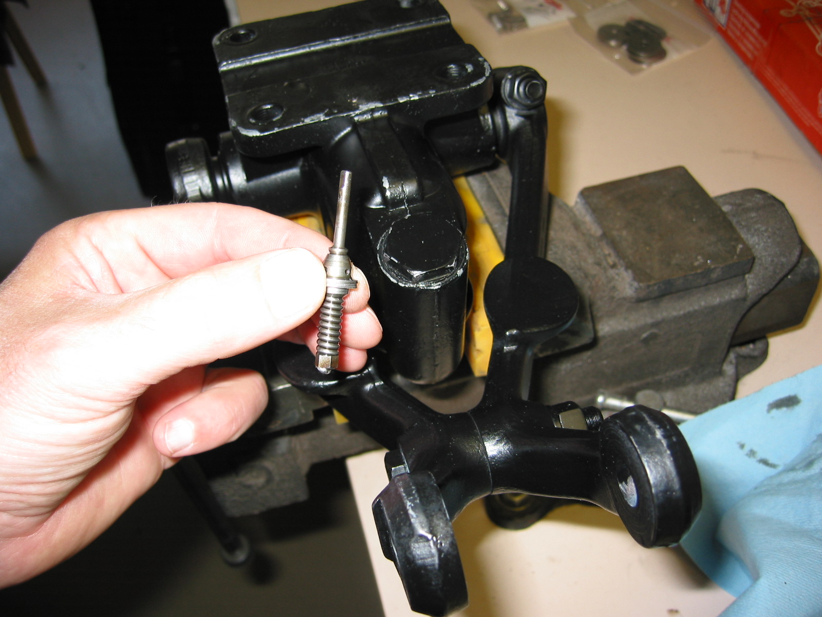
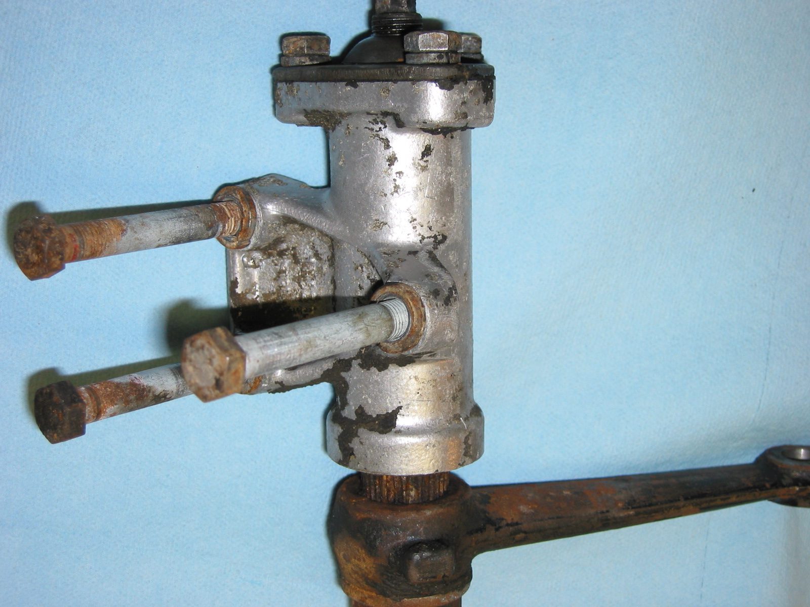
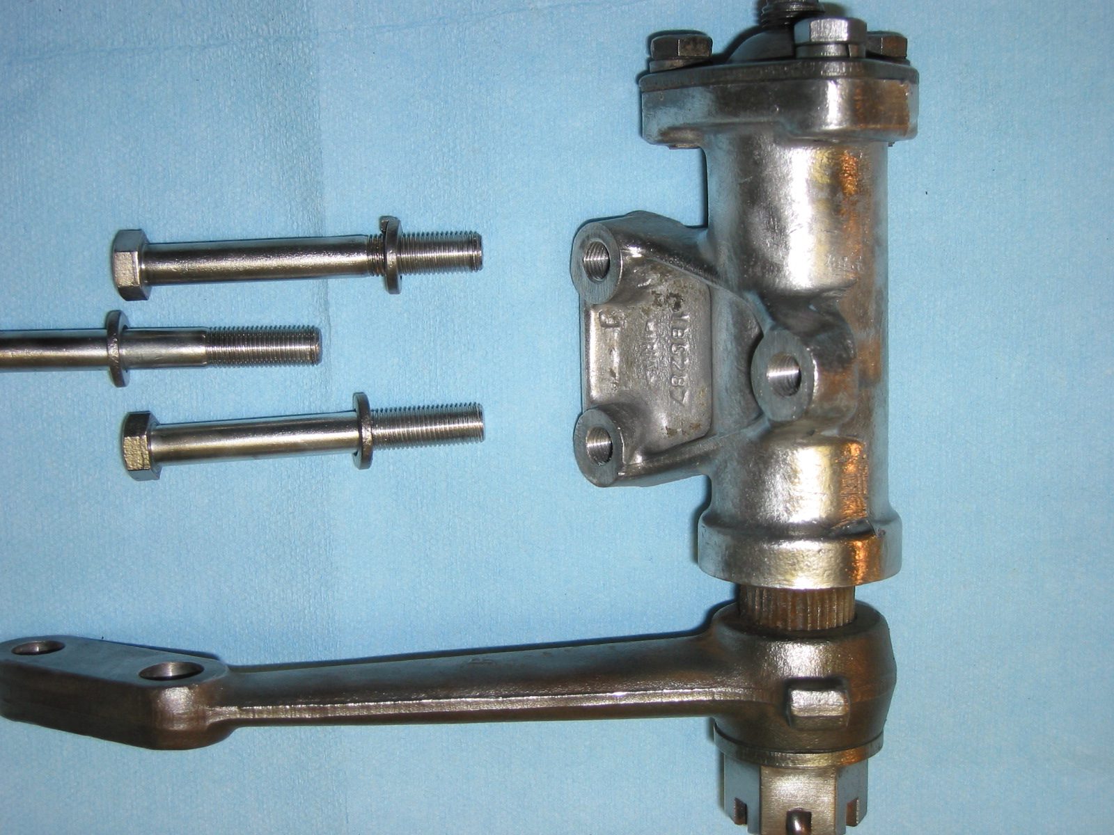
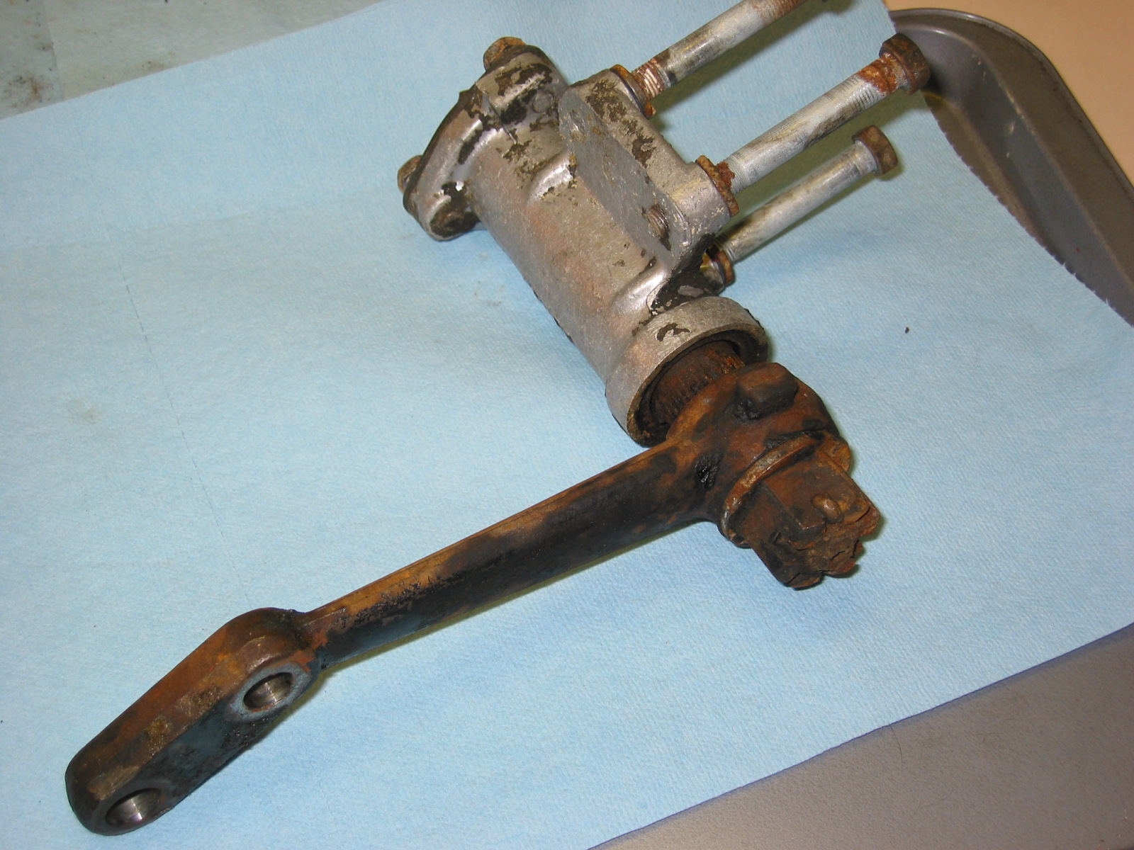
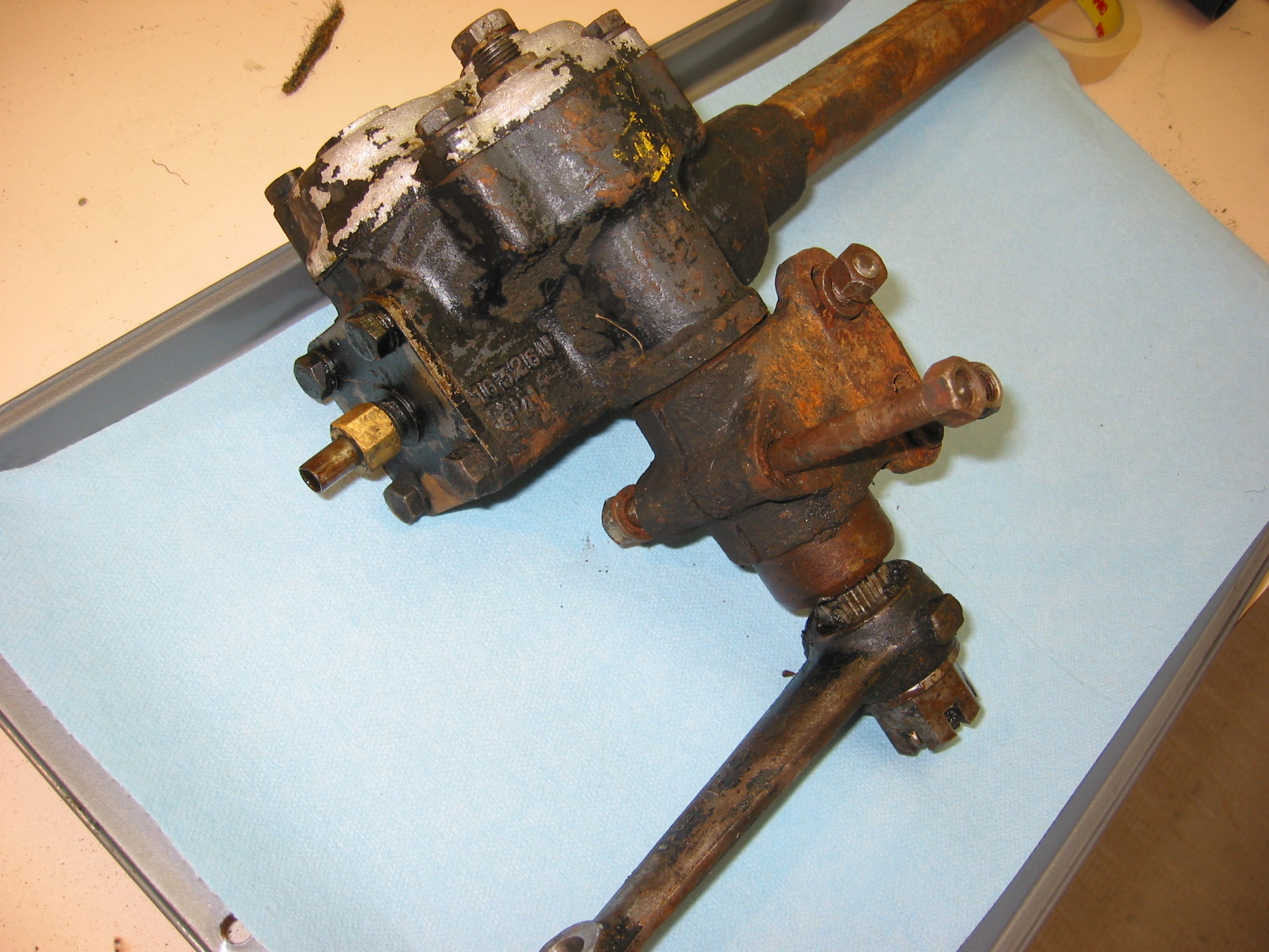
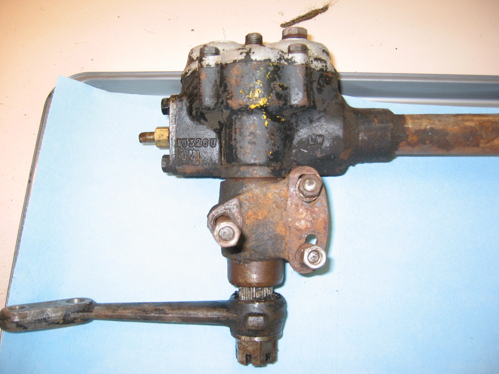
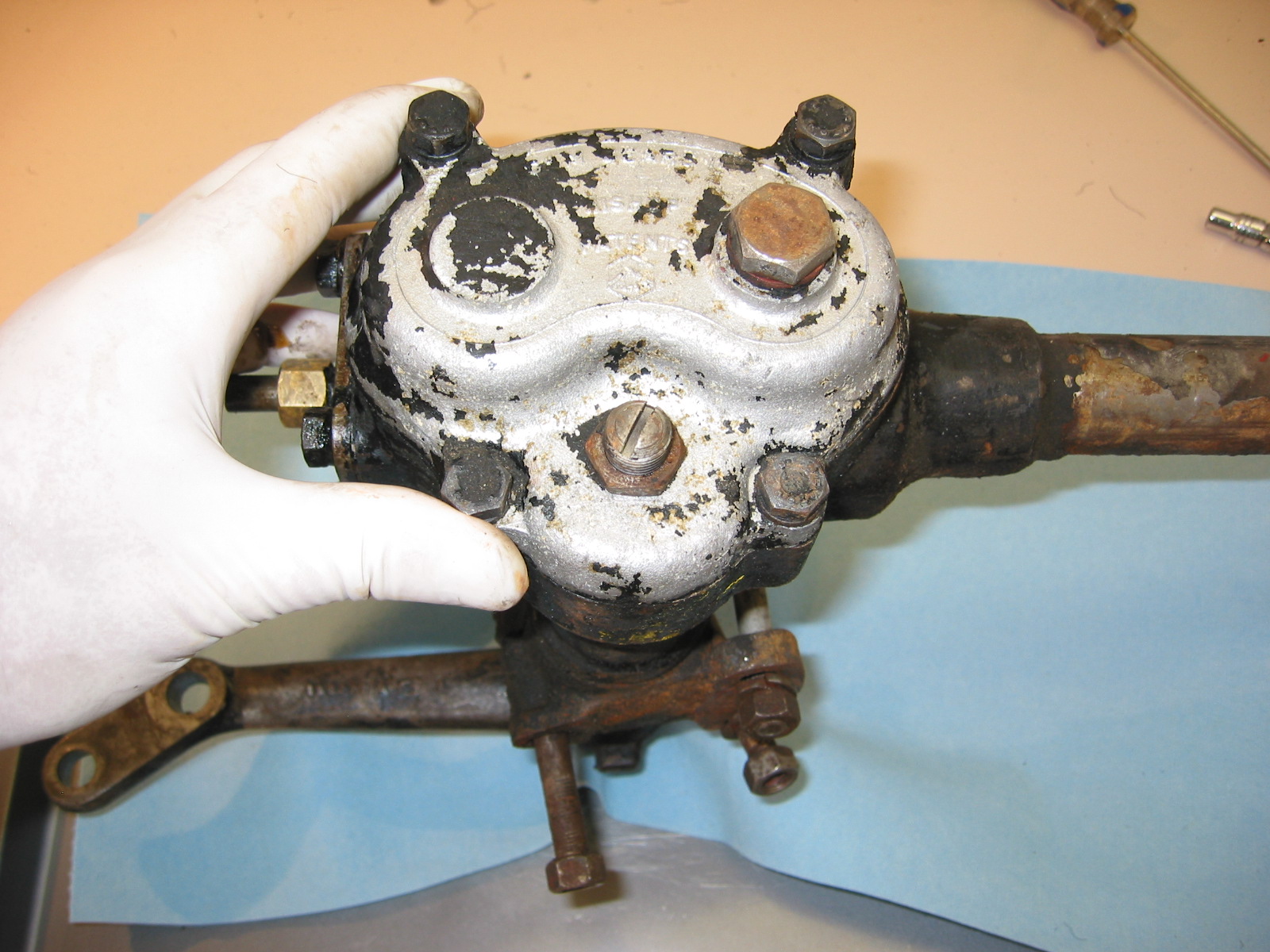
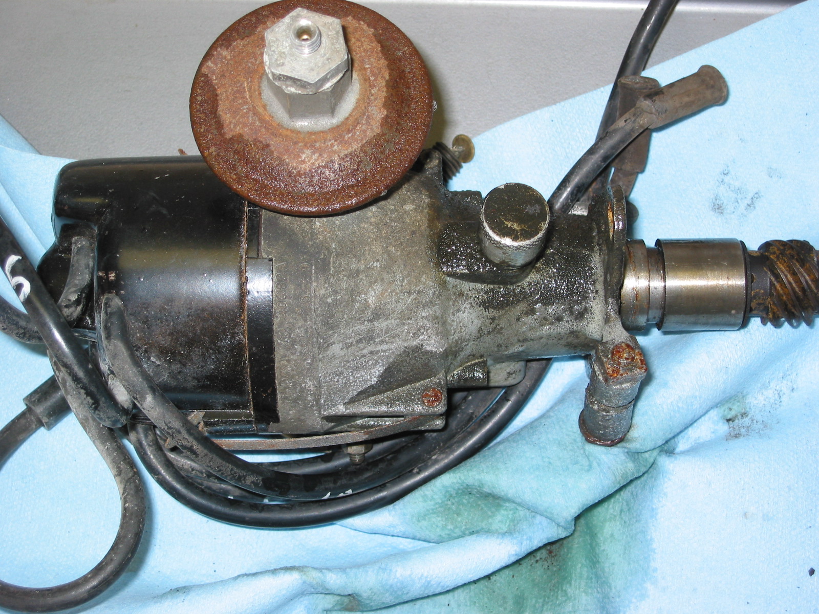
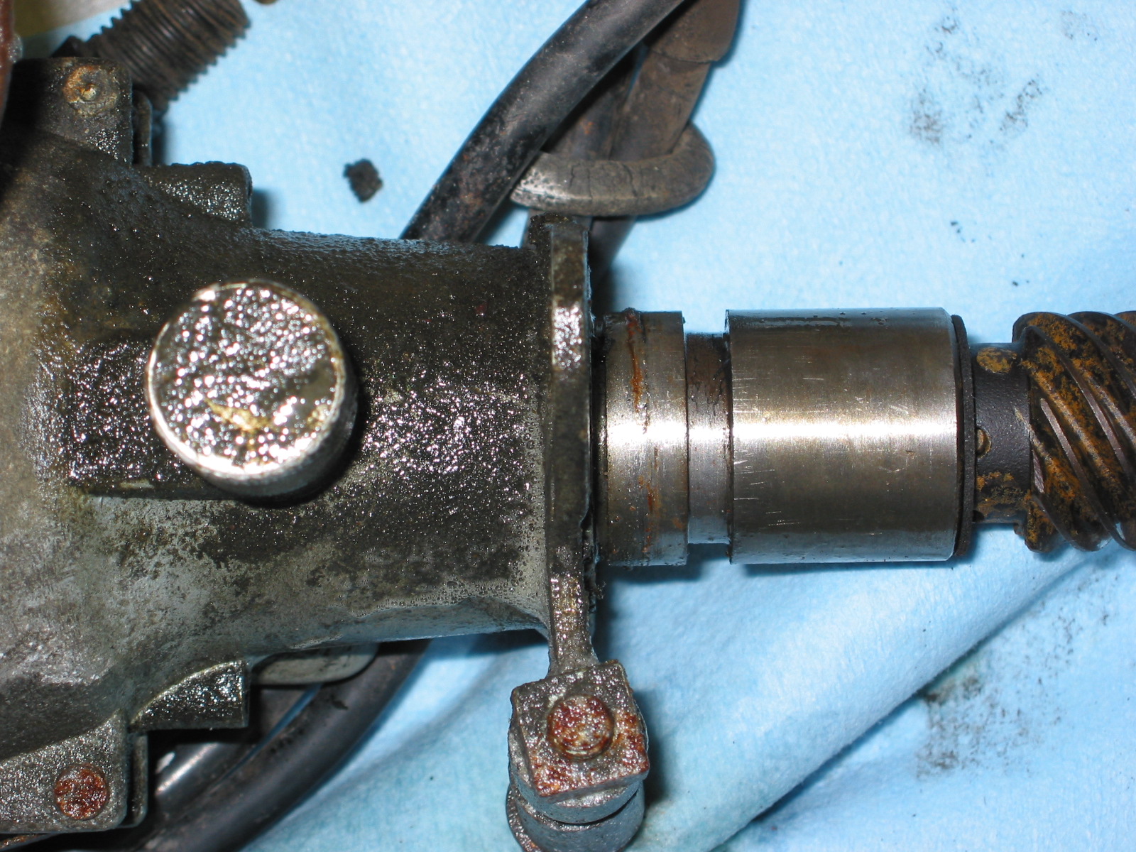
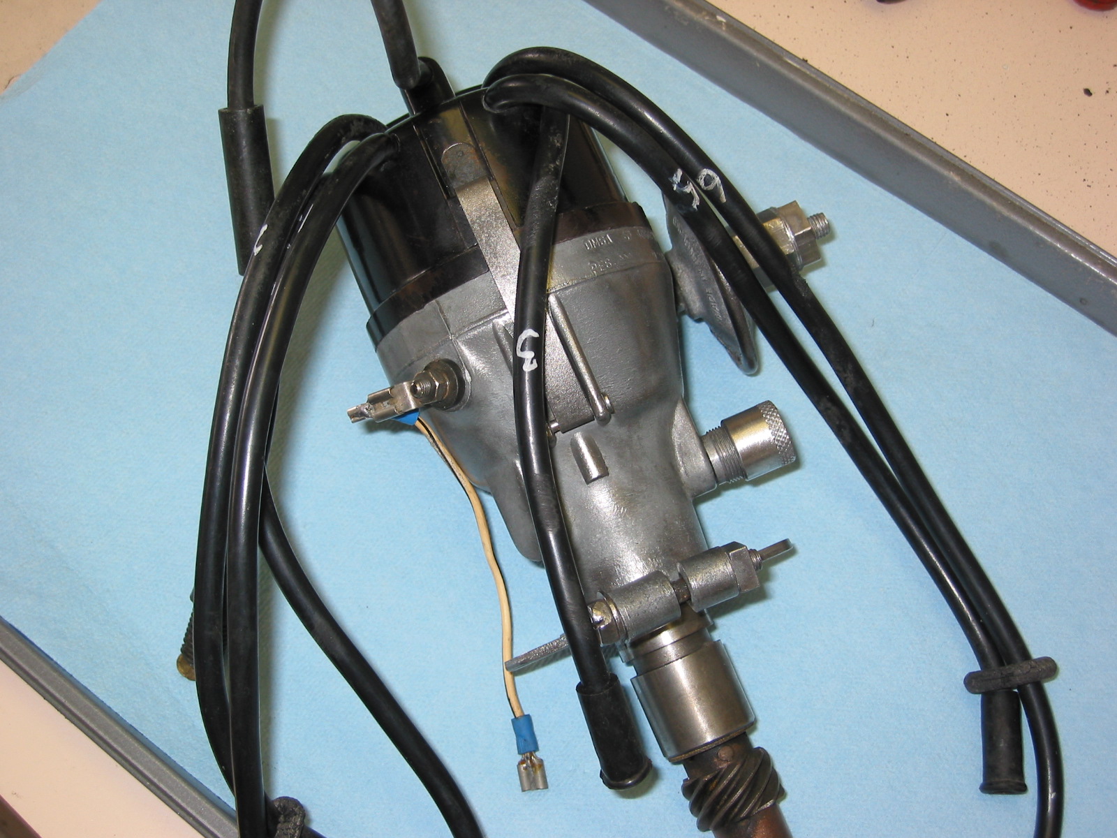
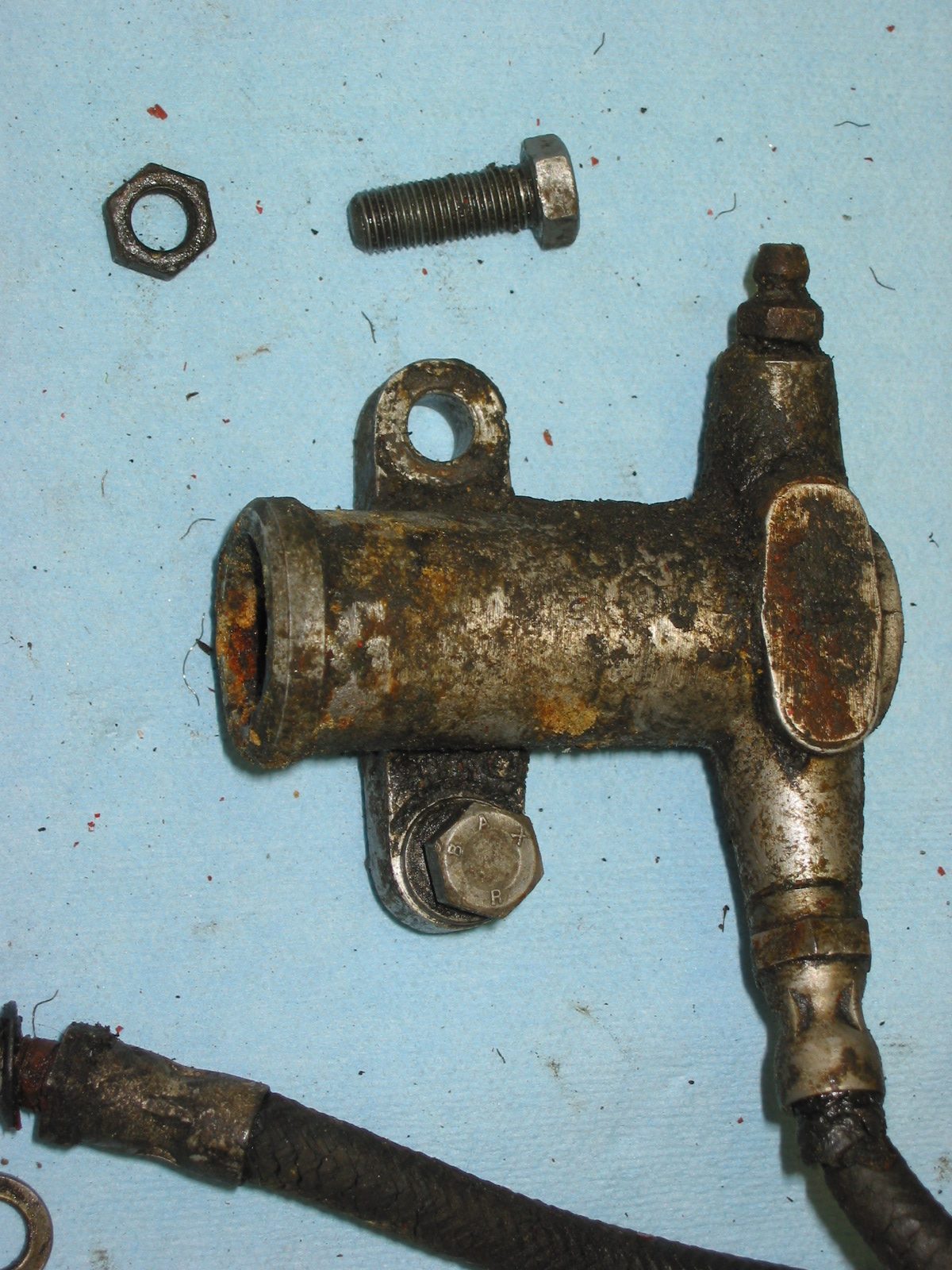
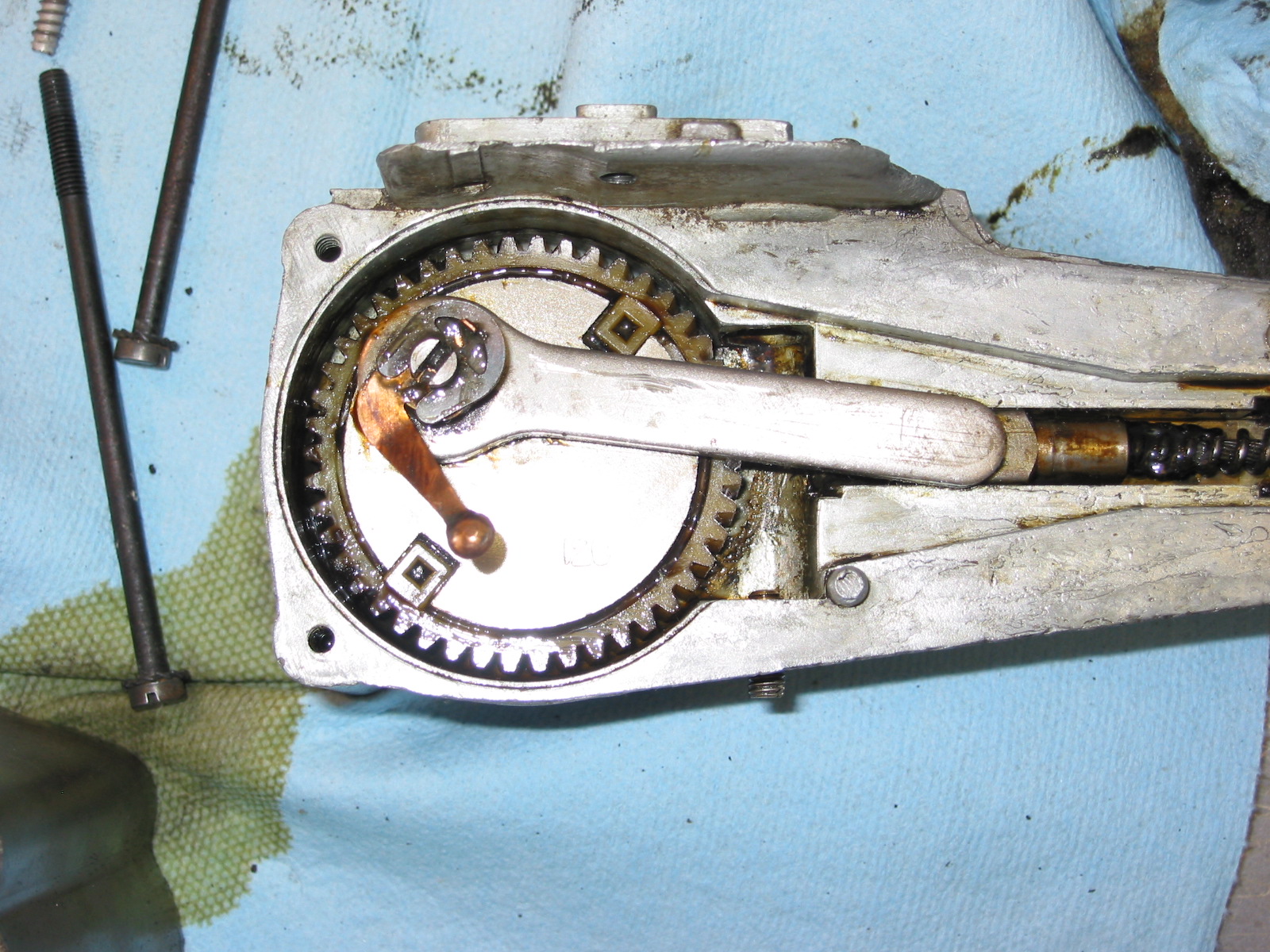
The Jaguar MK2 used a Burman F.3 steering unit as a standard fitting. In some cases the steering was power assisted, available as an option, but not on my particular car. The Burman unit is a recirculating ball type in which motion is transmitted from the inner column worm gear to the rocker shaft by means of a nut running on a continuous tram of steel balls.
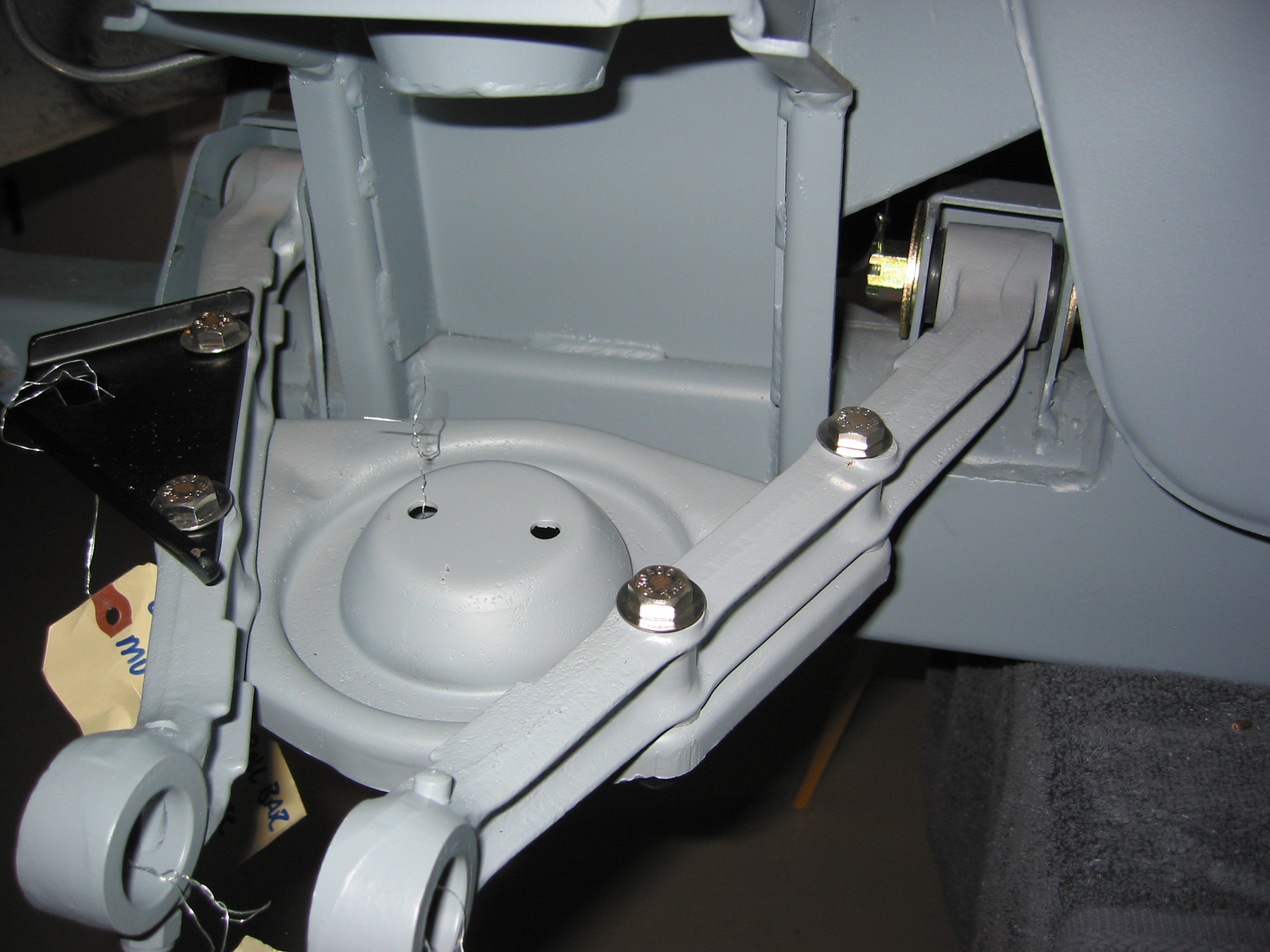
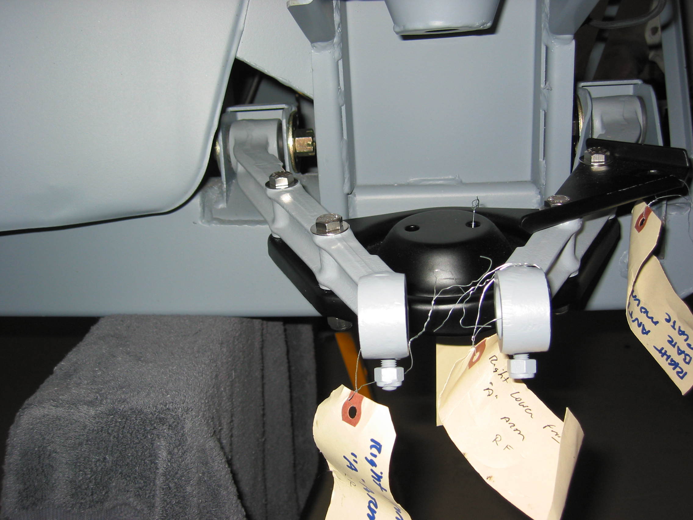
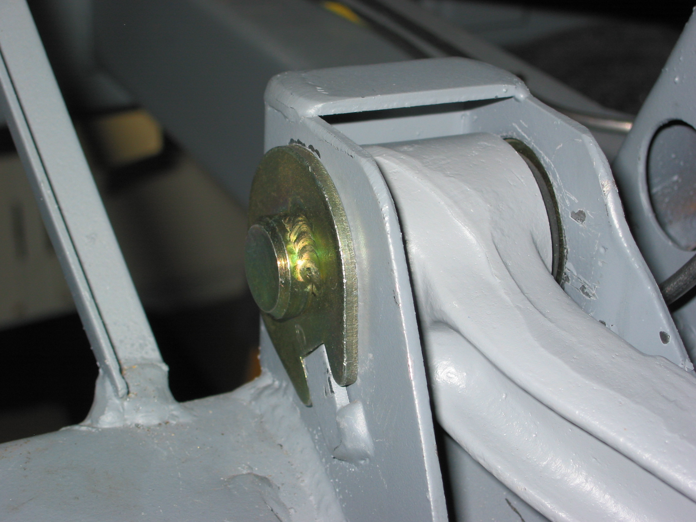
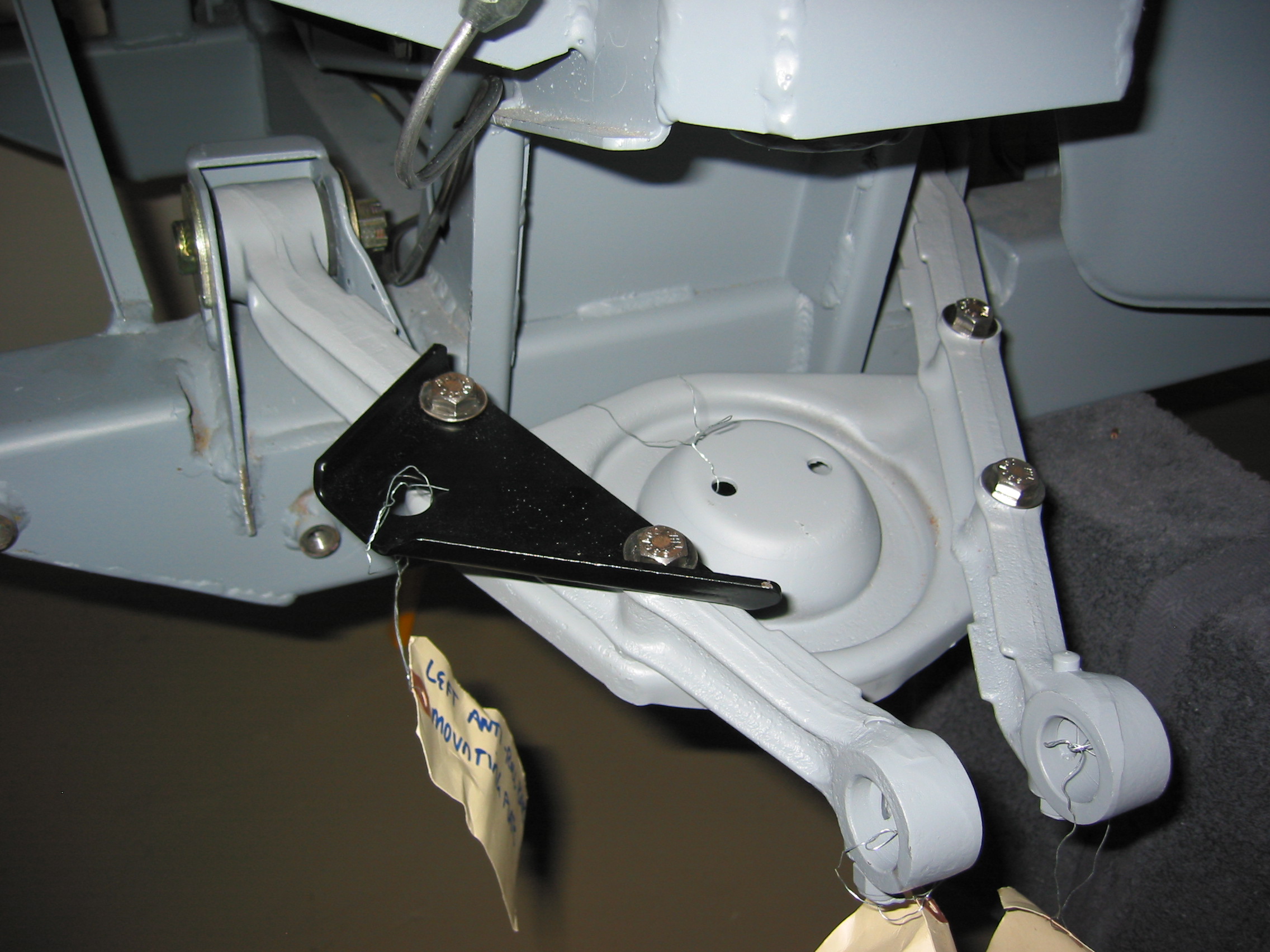
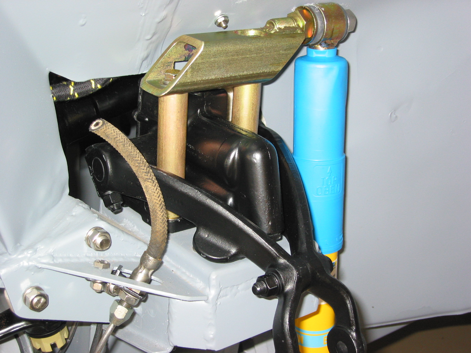
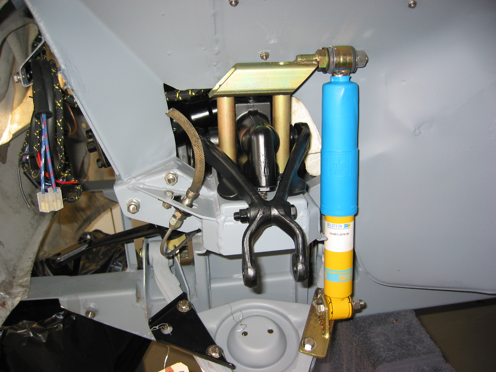
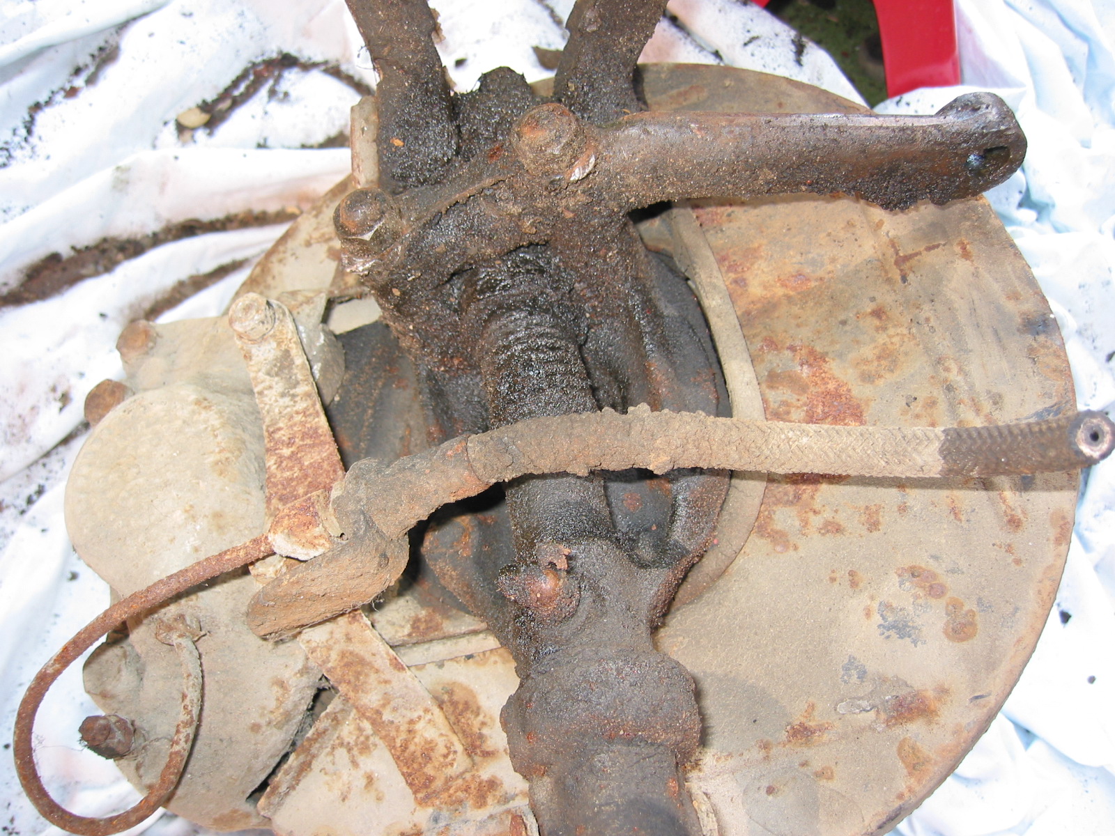
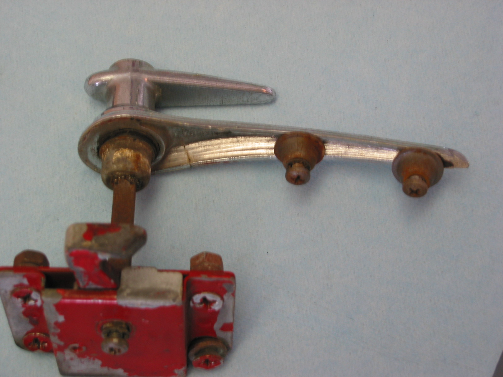
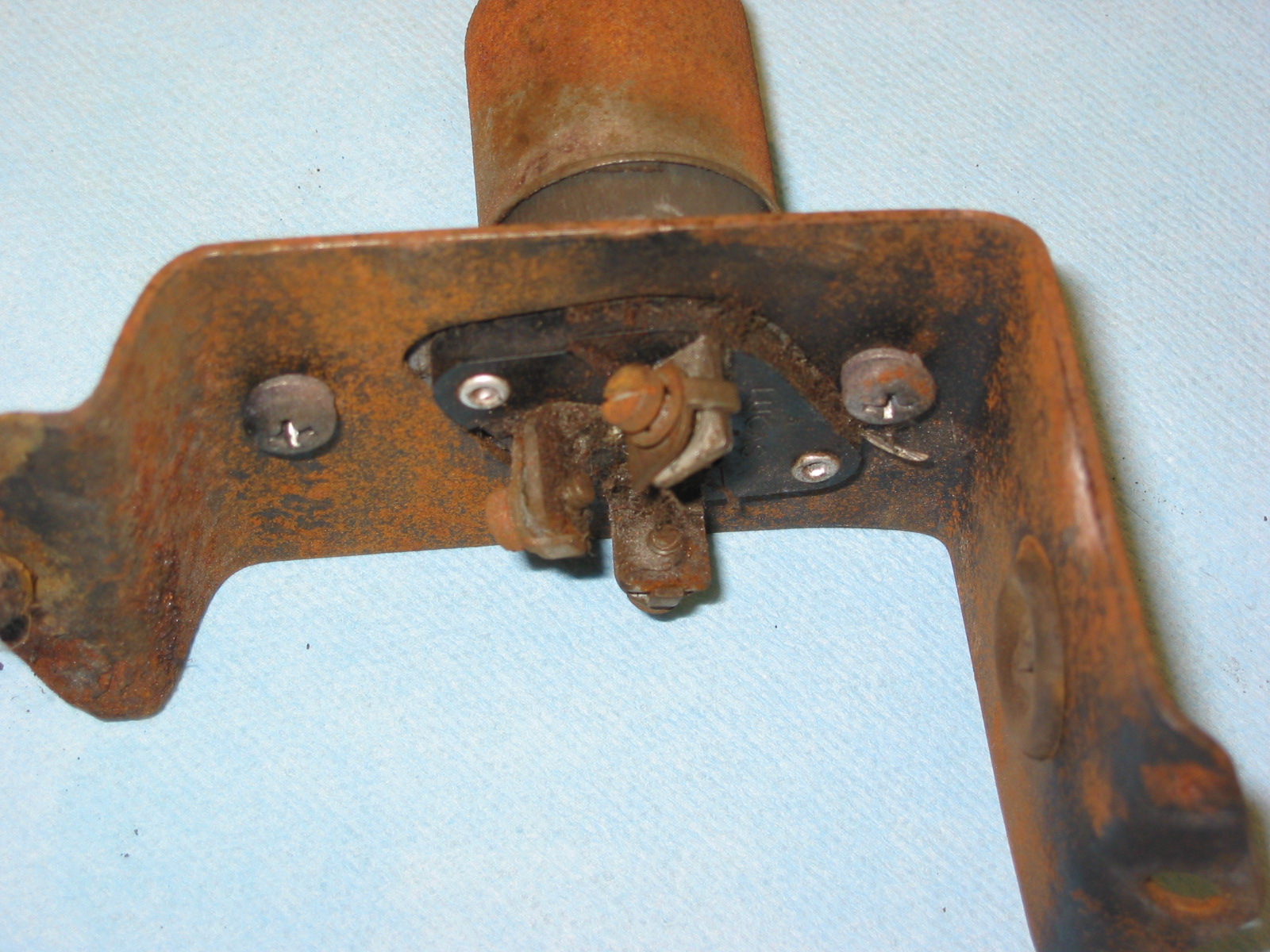
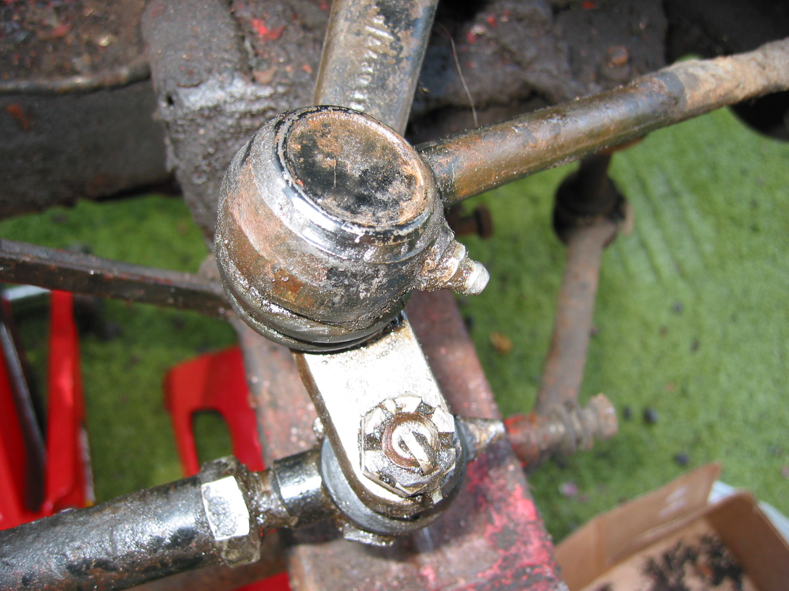
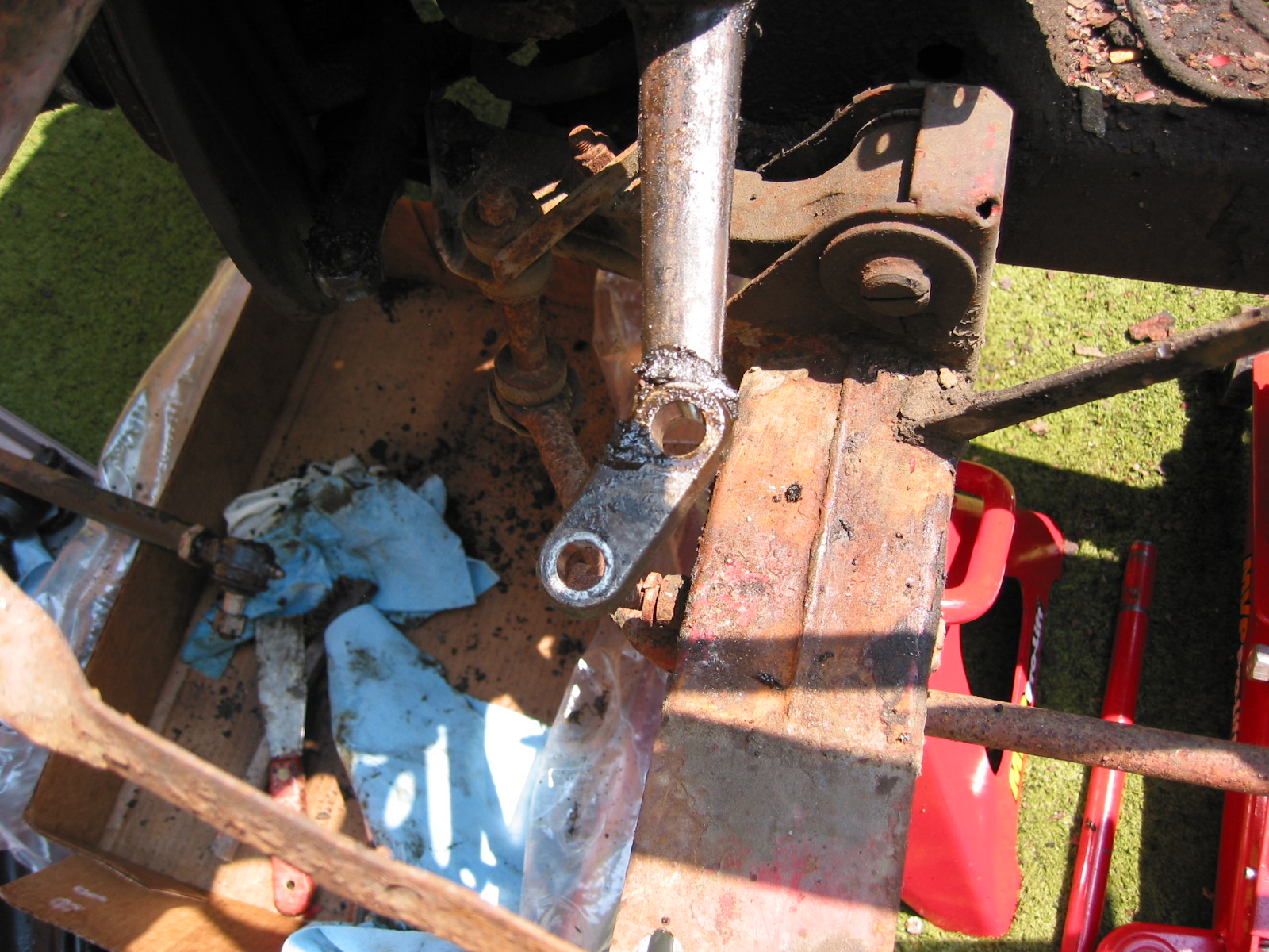
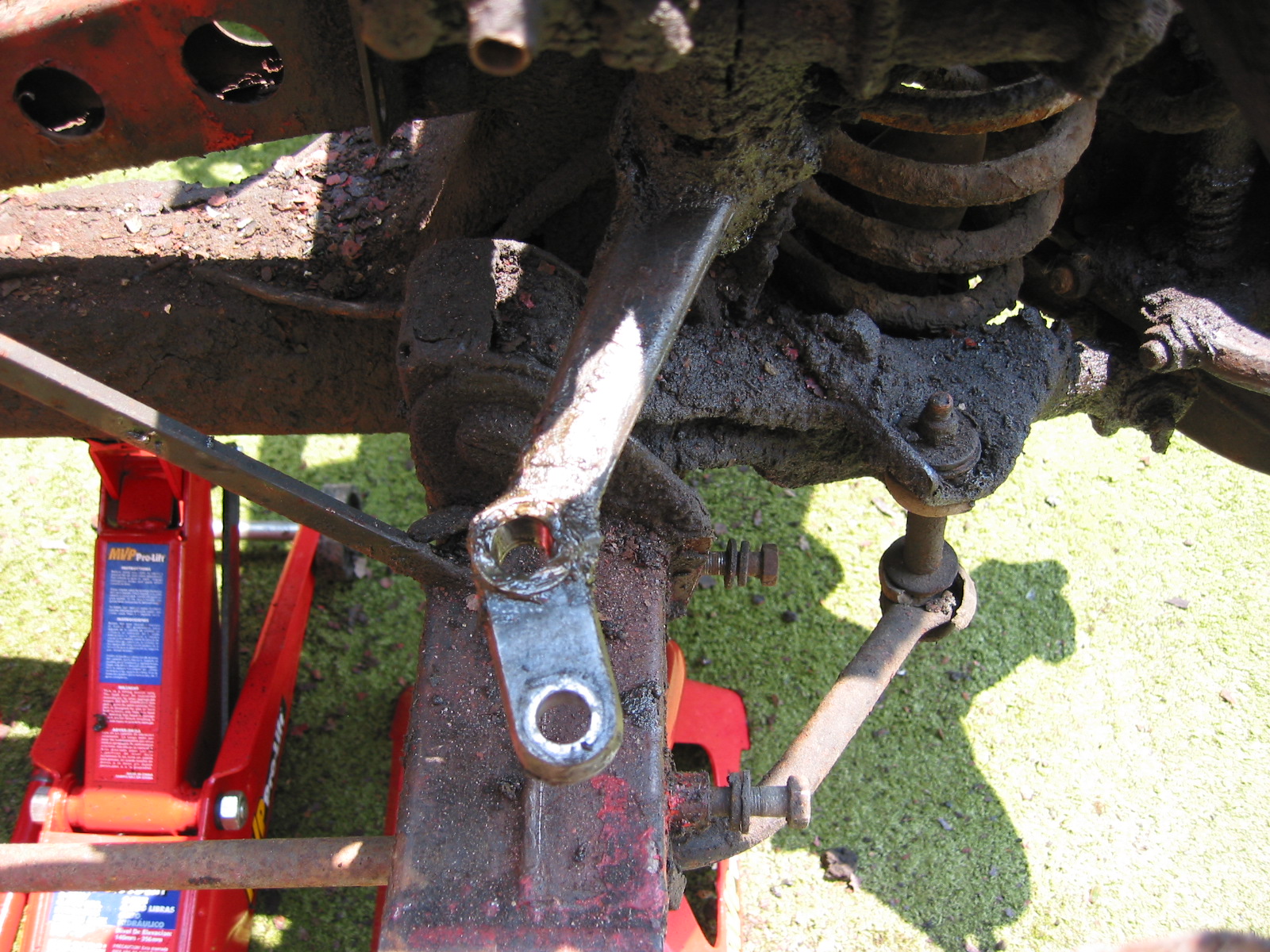
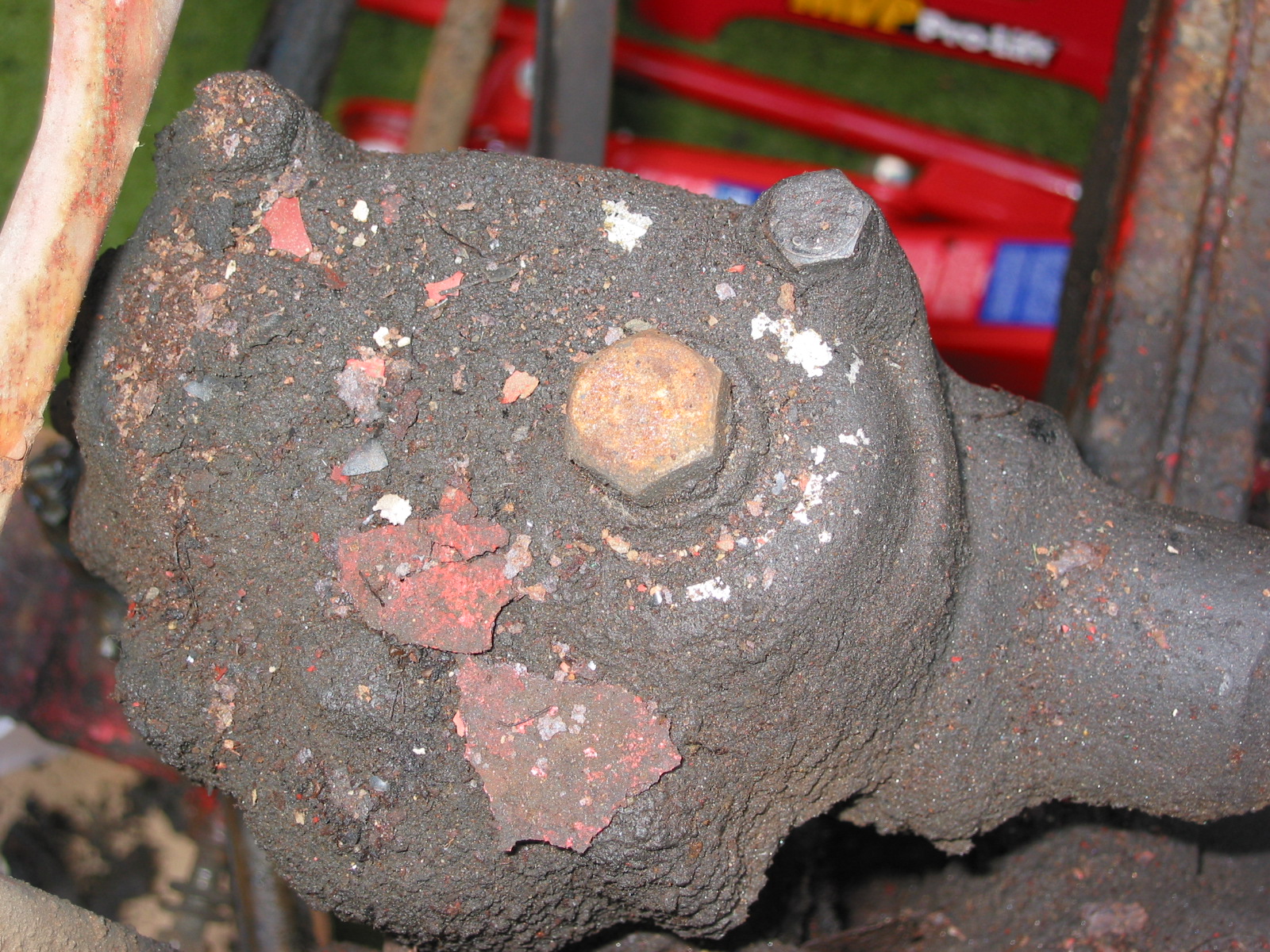
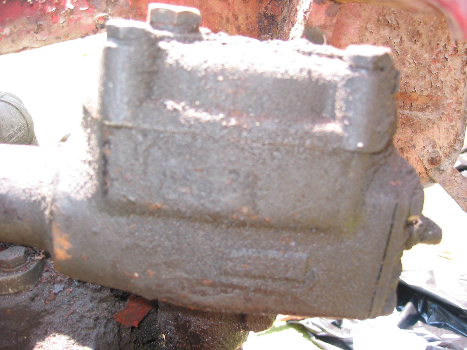
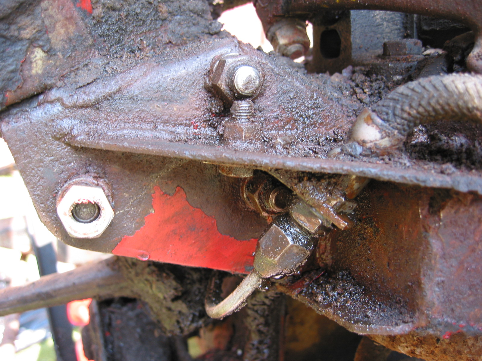
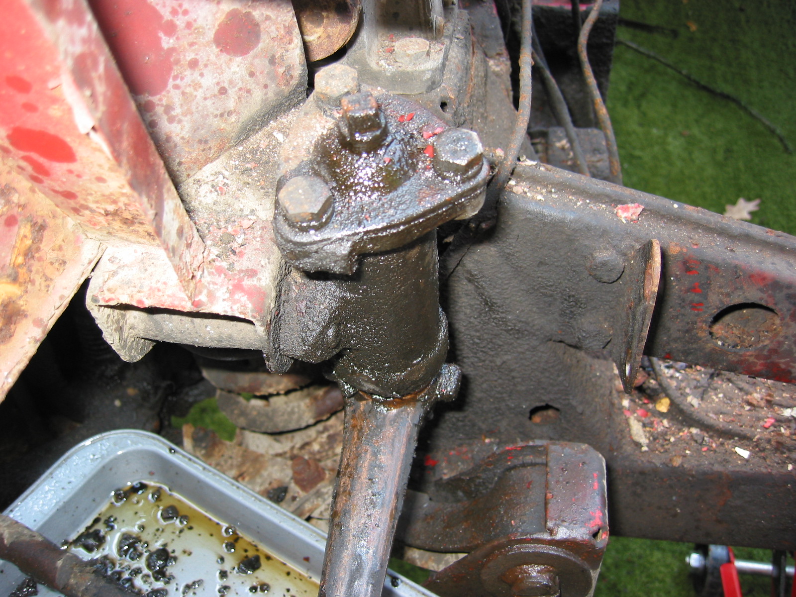
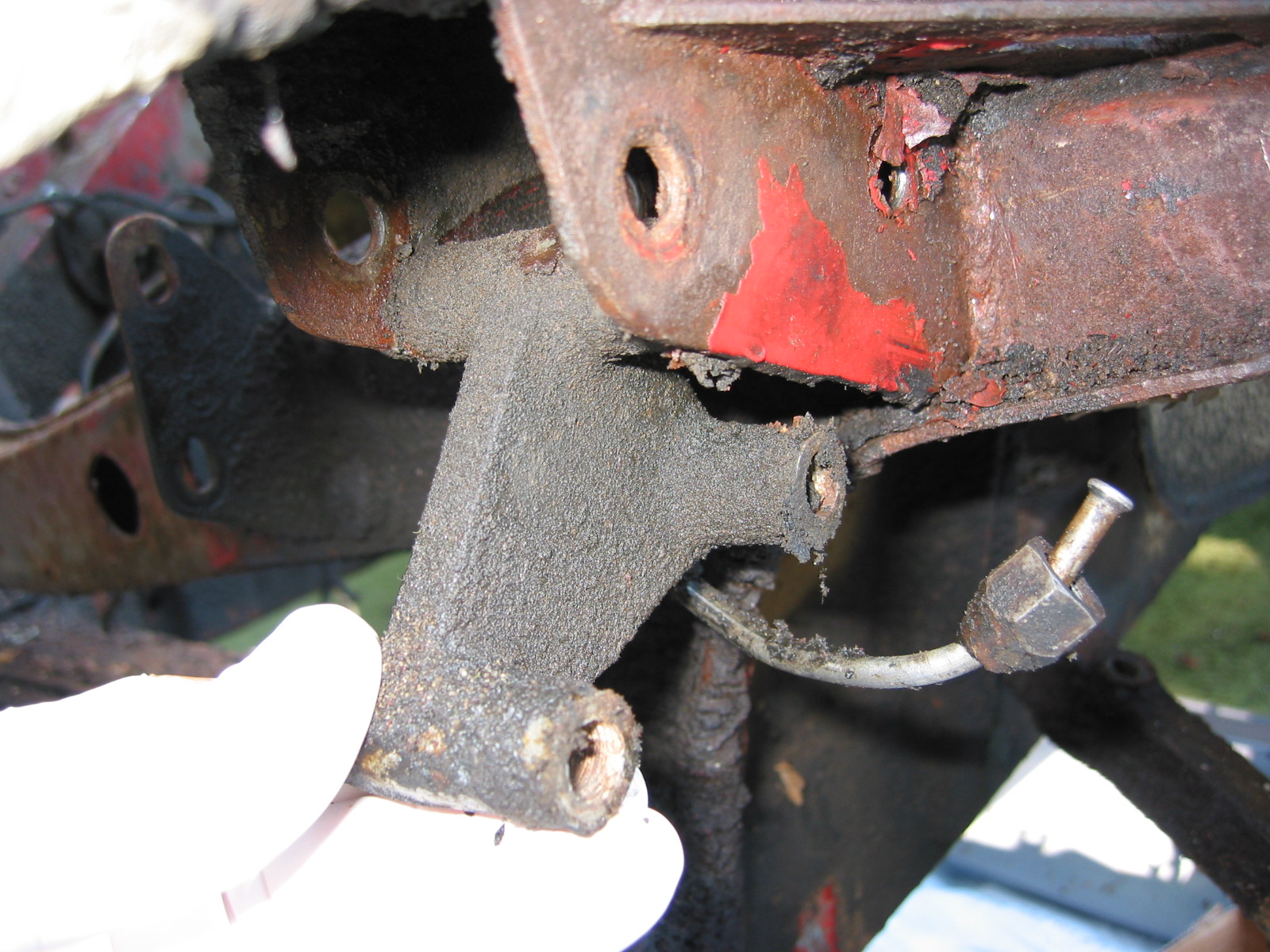
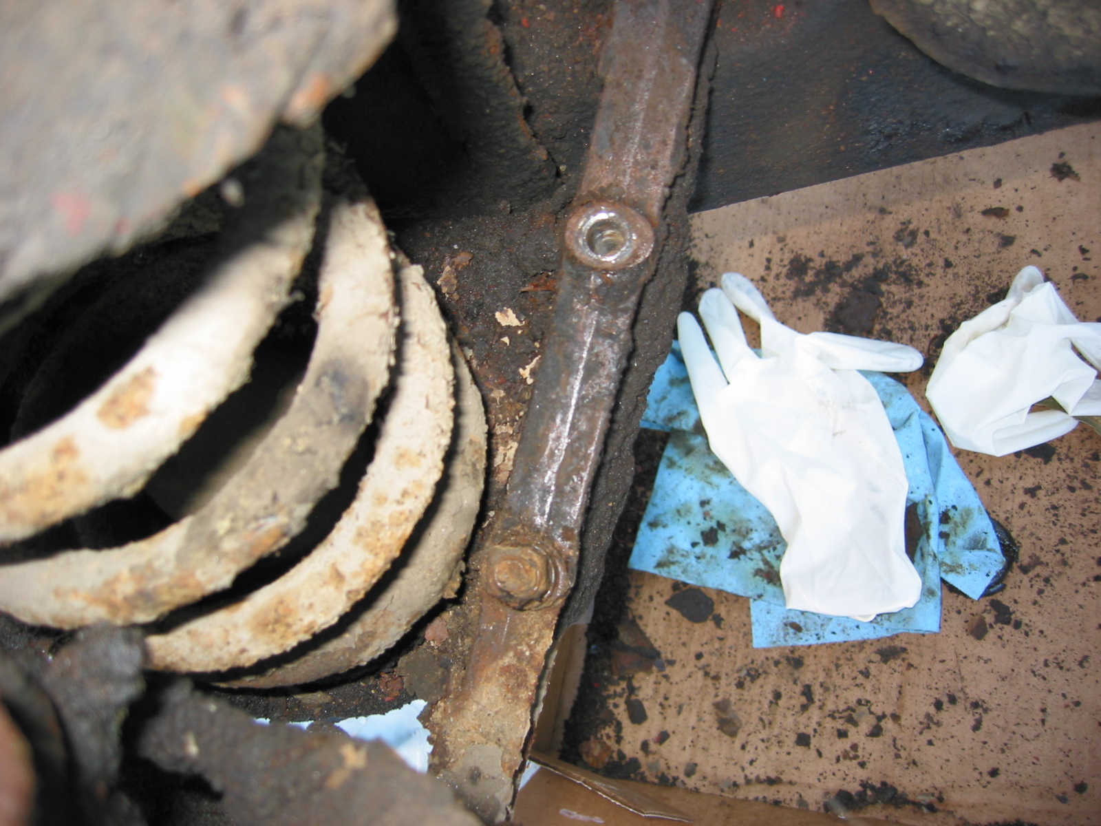
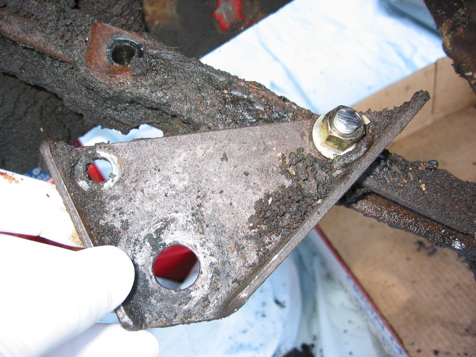
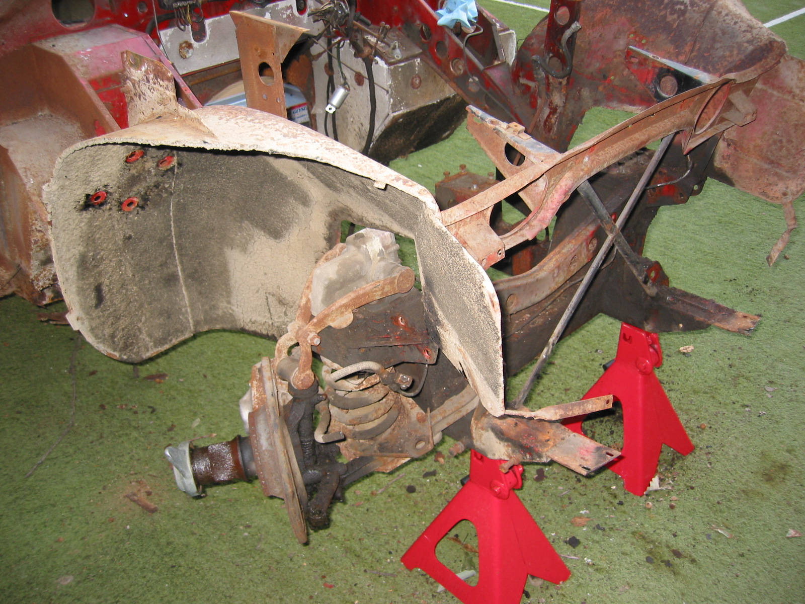
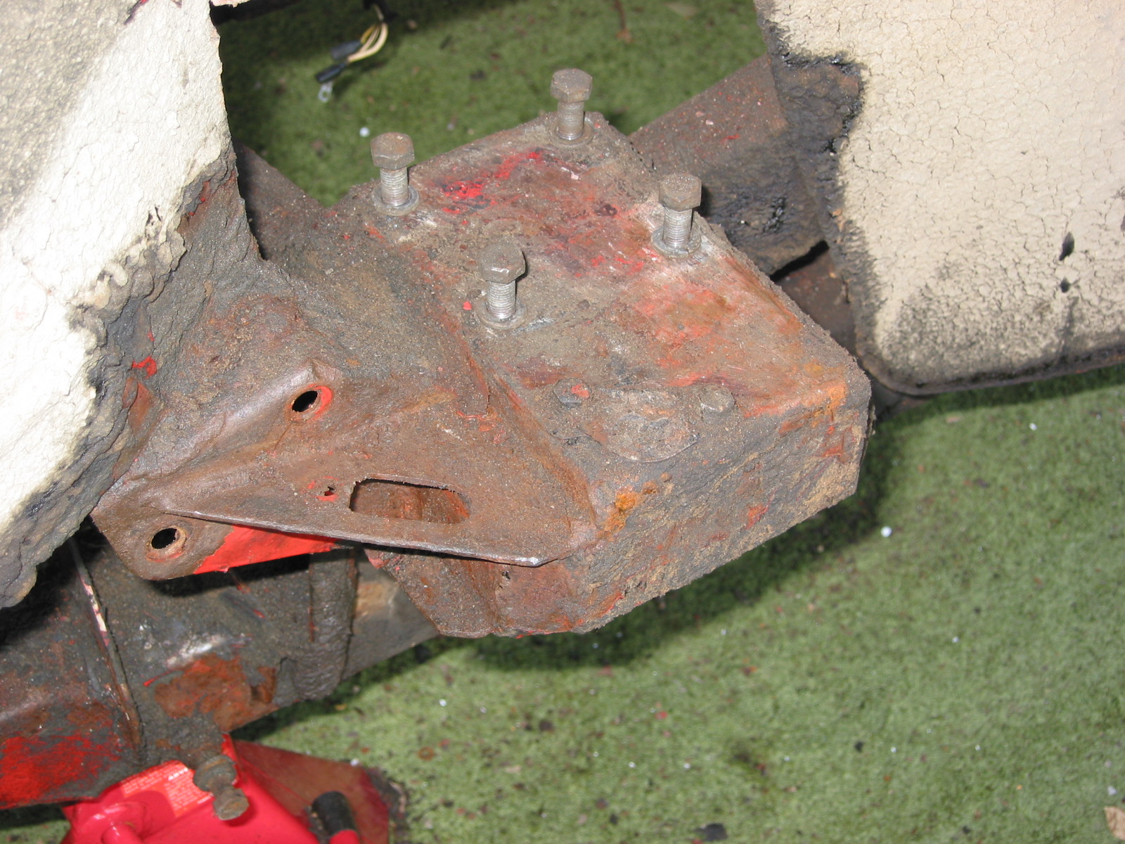
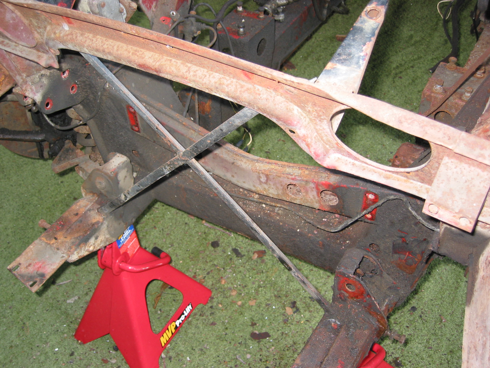
The image below illustrates the mounting of the steering box and steering idler to the rear side of the front suspension cross member assembly:

Steering Schematic
Rack & Pinion Steering Modification
I had not done much reading about Jaguar MK2s before it became clear that many owners were modifying the steering on their cars to incorporate power assisted rack and pinion and eliminate the original recirculating ball system. A number of Jaguar parts vendors sell partial and full kits to make the conversion to rack & pinion, some power assisted, some not. After doing more research I decided to purchase an electric power assisted conversion kit sold by M & C Wilkinson in the UK.
Wilkinson states that “We use a brand new short tower steering rack from a later XJ model which is then modified to fit the MK2. The pump we use is from a modern car. The LHD rack we provide is a brand new short tower rack. The long tower rack can not be used in the conversion. The tie rod ends on the rack are then modified to accept imperial track rod ends as fitted in period.”
The Wilkinson conversion kit contains the following components:
Pump/reservoir, pump bracket, fixing kit, fuse box, connector blocks, wiring, connectors, alternator, pulley – single or double, fitting kit, steering rack, rack brackets, rack bushes, track rod ends, racking fitting kit, column tube, steering pipes, instructions, a cutting template and a wiring diagram.

Wilkinson R & P Kit Components
The kit provides a very helpful set of PAS ELEC INSTRUCTIONS MkII compressed. To assist in my planning for a revised wiring diagram and harness I enquired about the amperage requirement of the pump motor. M&C Wilkinson responded, stating:
“The power steering pump uses approximately 40 amps at maximum draw which is slow speed/full lock.” He went on to say, “The power steering pump is pressure sensitive meaning it automatically detects the amount of assistance required at each turn of the wheel. Therefore, when parking the vehicle at low speed and with high resistance on the tyre maximum use of the pump is required therefore, it uses up to 40 amps in the particular type of instance. When you are driving at 70 mph in a straight line the pump recognises virtually no assistance is needed and therefore, the steering wheel is stiffened by the pump so it is not moving dramatically from right to left. This means in this instance that the pump will be drawing virtually no amps whatsoever.
We do not know how this is accomplished without a computer but this type of system has been fitted to cars for the last 15-20 years.”
As a first step in the installation process, I wanted to trial fit the rack and other components associated with the front suspension cross member assembly.
Adding the rack and pinion will also impact the ideal camber and castor settings. As Paul on the Saloon-Lovers Forum indicates:
“The factory alignment specs call for positive camber, but if you are running modern tires, some negative camber is much better. I try for somewhere between 0.5- 1.0 negative with 205 VR tires. A bit more on the right side for the crown in the road makes it track straighter. If you run more than 1 degree negative camber on the road, you will wear out the inside edge of the front tires in less than 10,000 miles. This is the price of grip and rotating the tires a lot helps. The factory spec for castor is also not good for a rack conversion, 2-3 degrees positive castor is closer to ideal.”
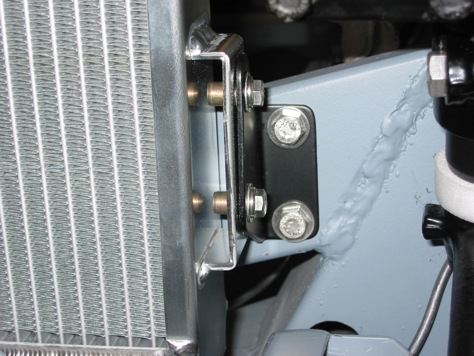
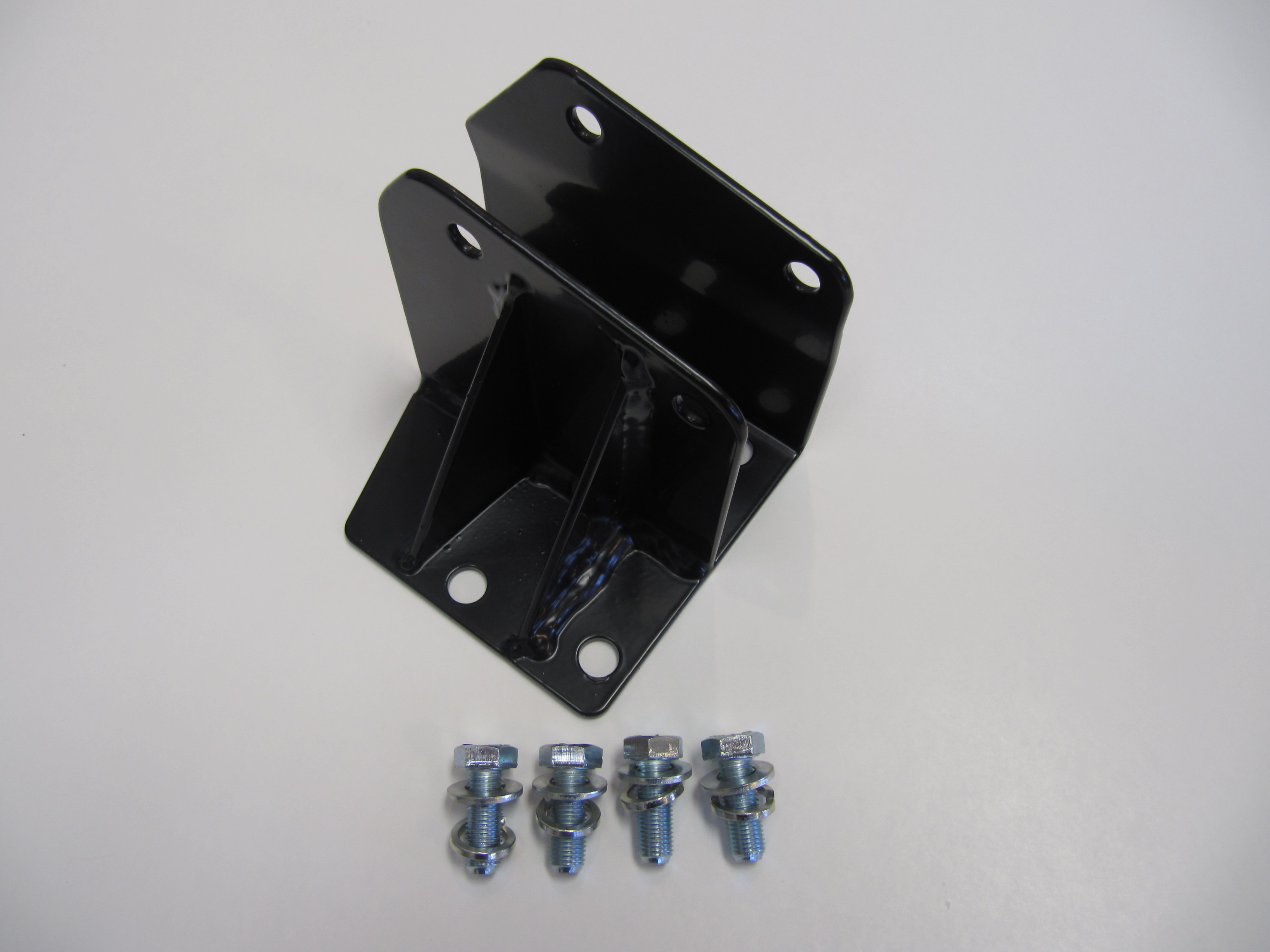
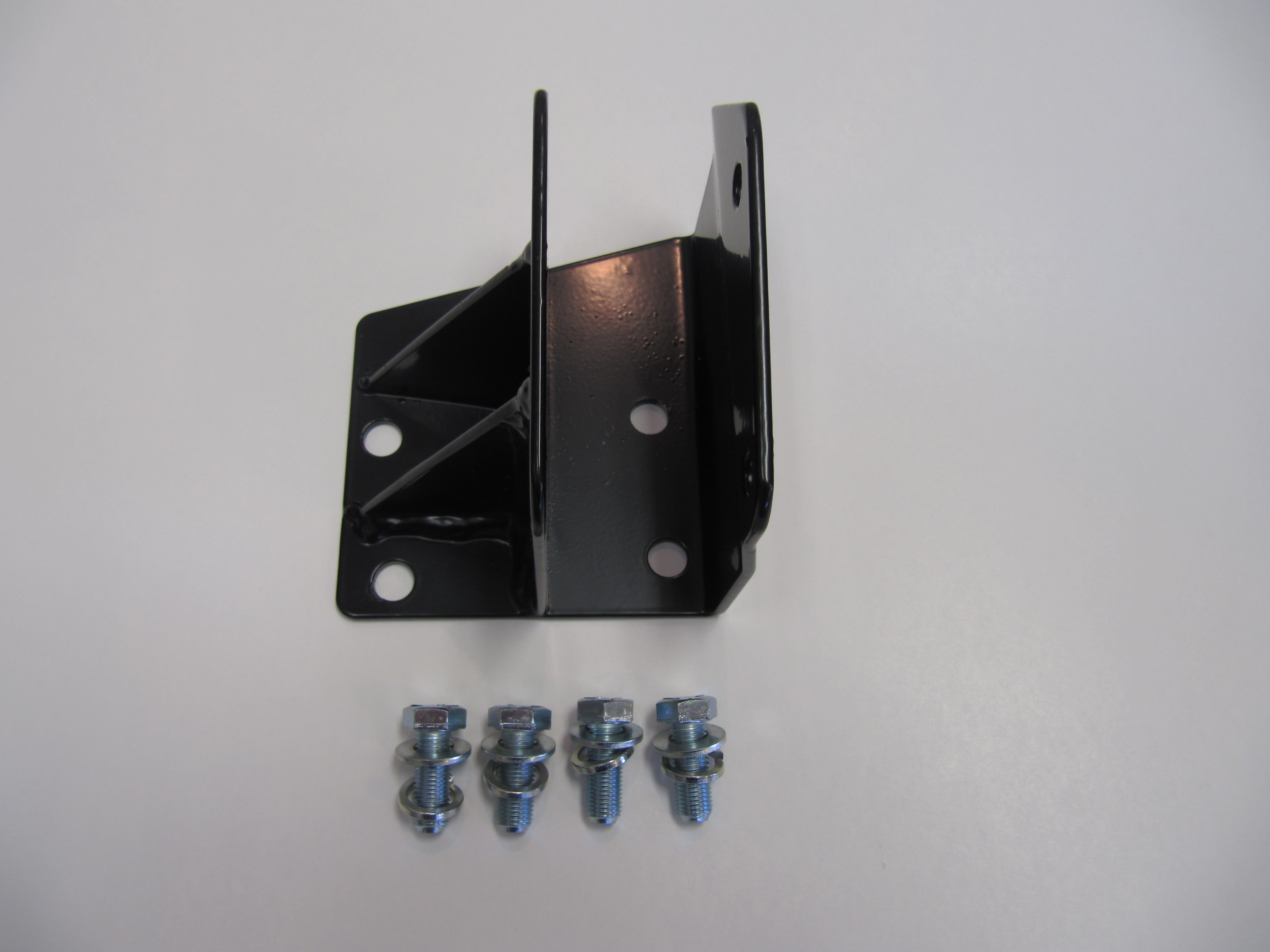
Rack Brackets
I began by bolting the supplied rack brackets to the cross member. This requires eight 3/8″ x 1″ – 24 bolts with split washers and flat washers that are supplied in the kit hardware.
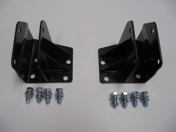
R & P Bracket Pair
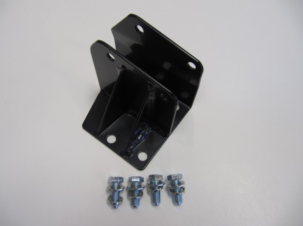
R & P Bracket
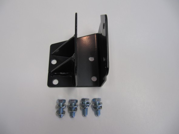
R & P Bracket

R & P Brackets Mounted RH

R & P Brackets Mounted
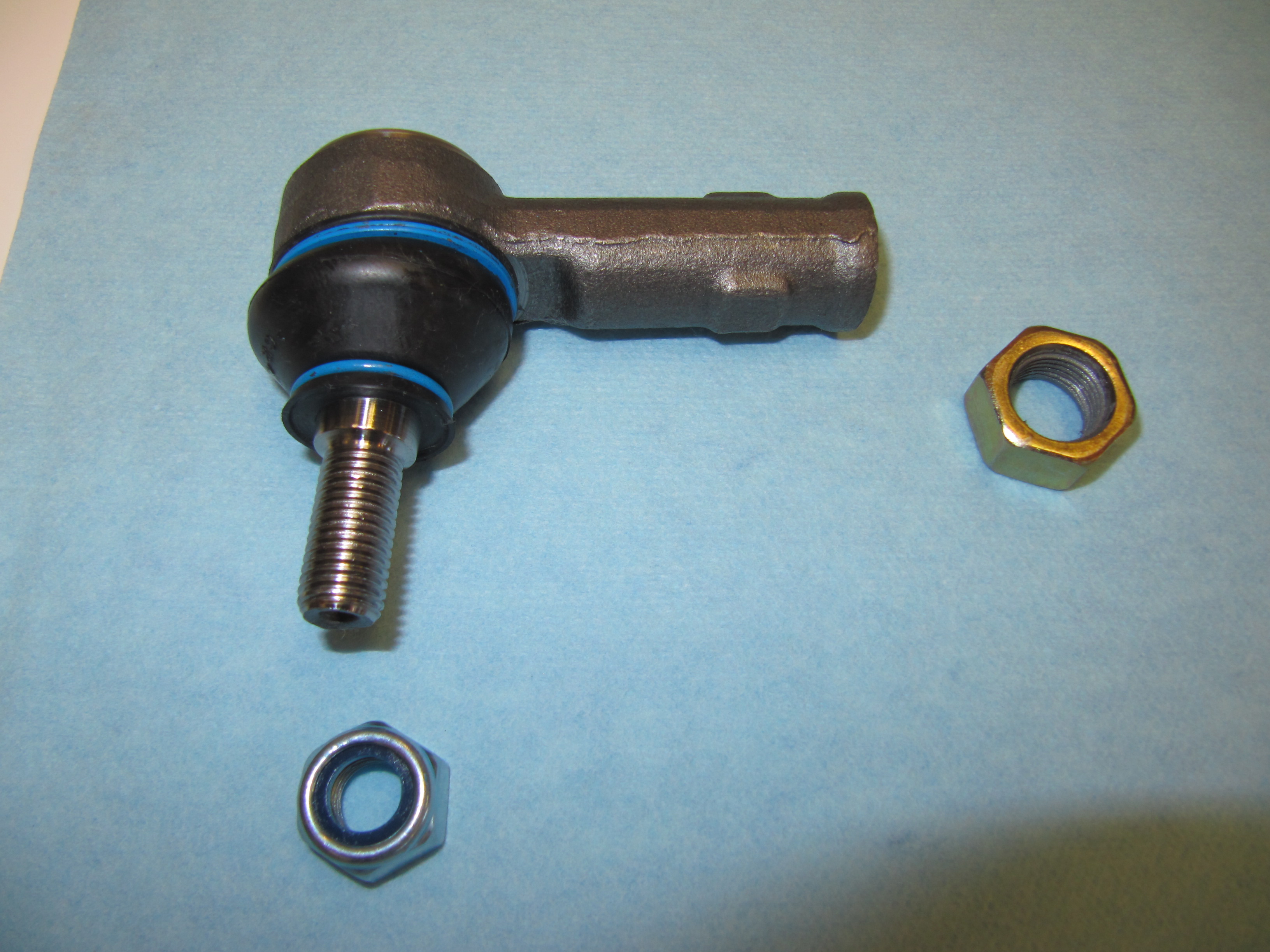
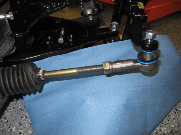
Tie Bars and Track Rod Ends
The kit’s directions call for removing 3/8″ from each end of the steering rack tie bars before fitting the track rod ends and lock nuts. I measured the 3/8″, put some masking tape around the threads, and cut off the ends with a grinding wheel. Then, again per the directions, I wound on the track rod ends fully and then backed off two full turns and tightened the locknuts by hand against the track rod end. The steering rack tie bar locknuts are 5/8″ – 18.
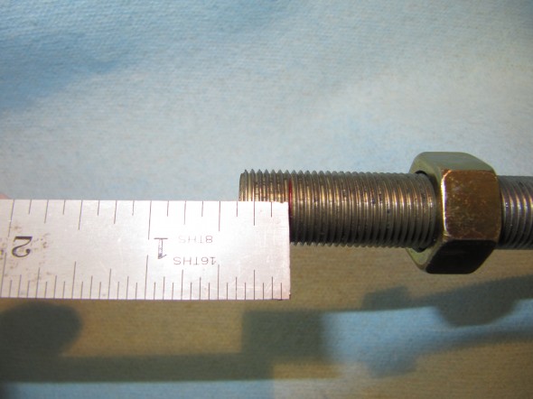
Shorten Tie Bar

Track Rod End
I then mounted the steering rack to the mounting brackets. On the LH side the rack is fastened to the bracket with two 5/16″ x 2 1/2″ – 24 hex head bolts with two flat washers and a 5/16″ – 24 nylock nuts. On the RH side the rack is fastened to the bracket with only one 5/16″ x 2 1/2″ – 24 hex head bolt with two flat washers and a 5/16″ -24 nylock nut.
LH Rack Mount to Bracket
RH Rack Mount to Bracket
RH Rack Mount to Bracket

LH Rack Mount to Bracket
Tie Rod Levers
After connecting the track rod ball joint pins to the tie rod levers with 1/2″ nylock nuts, I tightened the locknuts on the tie bars.

Tie Rod Levers

Tie Rod Levers
RH Rod End to Lever
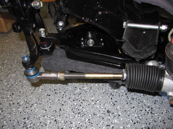
LH Rod End to Lever

Steering Rack to Cross Member
I then used POR-15 to paint sections of the steering rack for protection from corrosion.
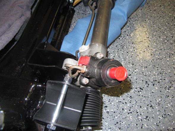
Power Steering Hydraulic Steel Pipes
The rack and supplied by M&C Wilkinson came with hard pipes. I decided to not use the pipes provided as they were extremely hard to bend.

Power Steering Steel Lines
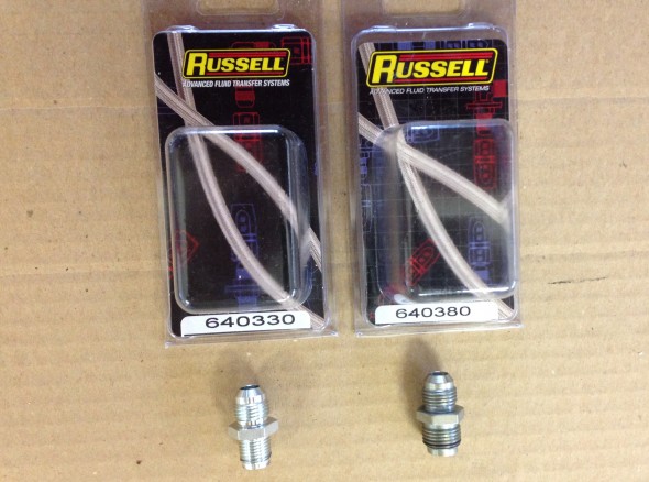
On the high pressure line/hose I used a Russell 1/2″-20 inverted flare to -6 part number 640330. While I purchased a similar fitting for the low pressure line/hose I ended up not using it and instead purchased a hard pipe and bent it to fit. The pipes were replaced with appropriate fittings.
Steering Rack Hose Fittings
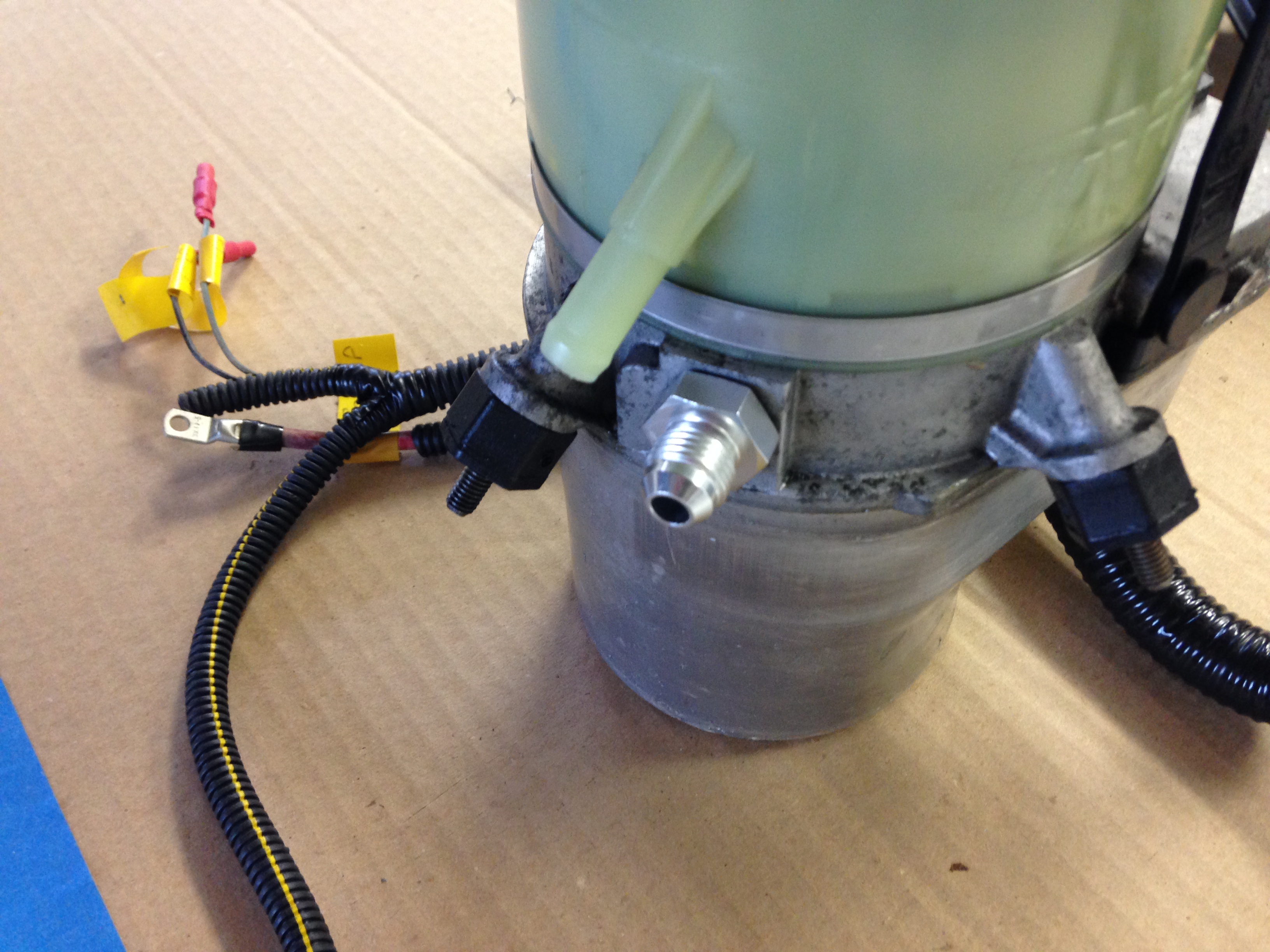
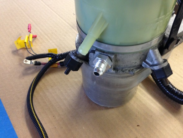
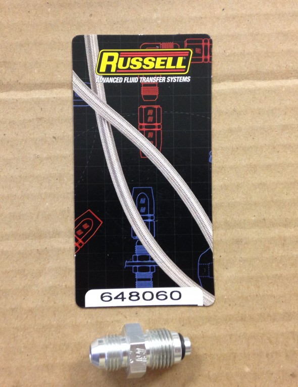
Although I am not ready to mount the hydraulic steering pump, I went ahead and ordered the hose fitting for the pump while I was ordering the other fittings. The pump pressure port is a 16mm x 1.5 O-ring Russell part#648060.
Special thanks to “GT6Steve” on the Jaguar Forums for providing this information. It saved me a lot of time!
I guess that I will try a hose clamp for the low pressure return side of the pump bottle as it is just a plastic slip fitting.
Hydraulic Pump Hose Fitting
Hydraulic Pump Russell Hose Fitting
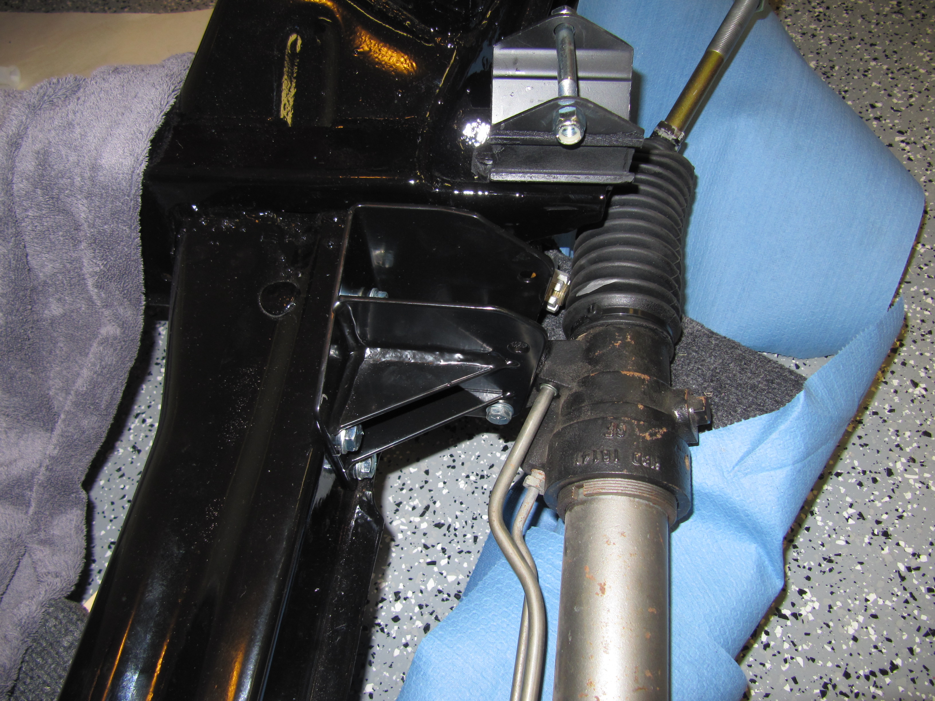
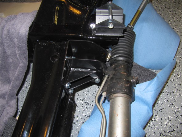
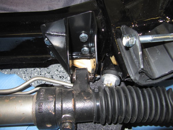
Rack and Pinion Steering Linkage
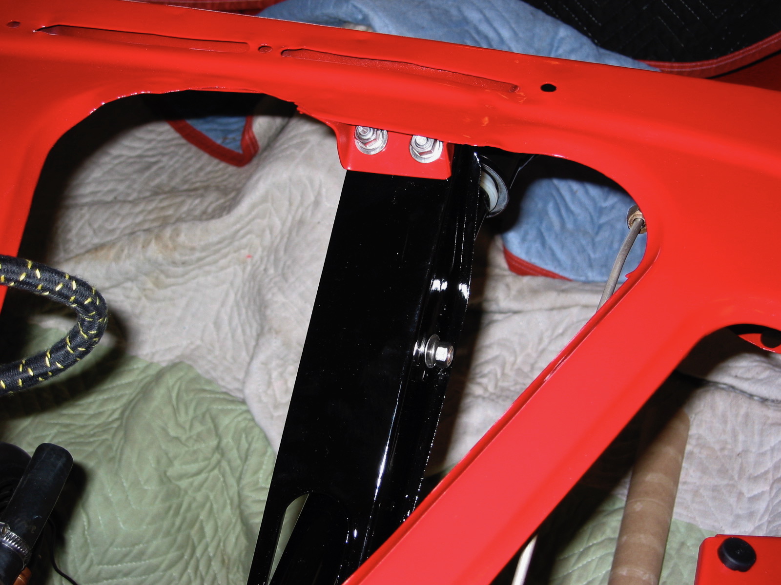
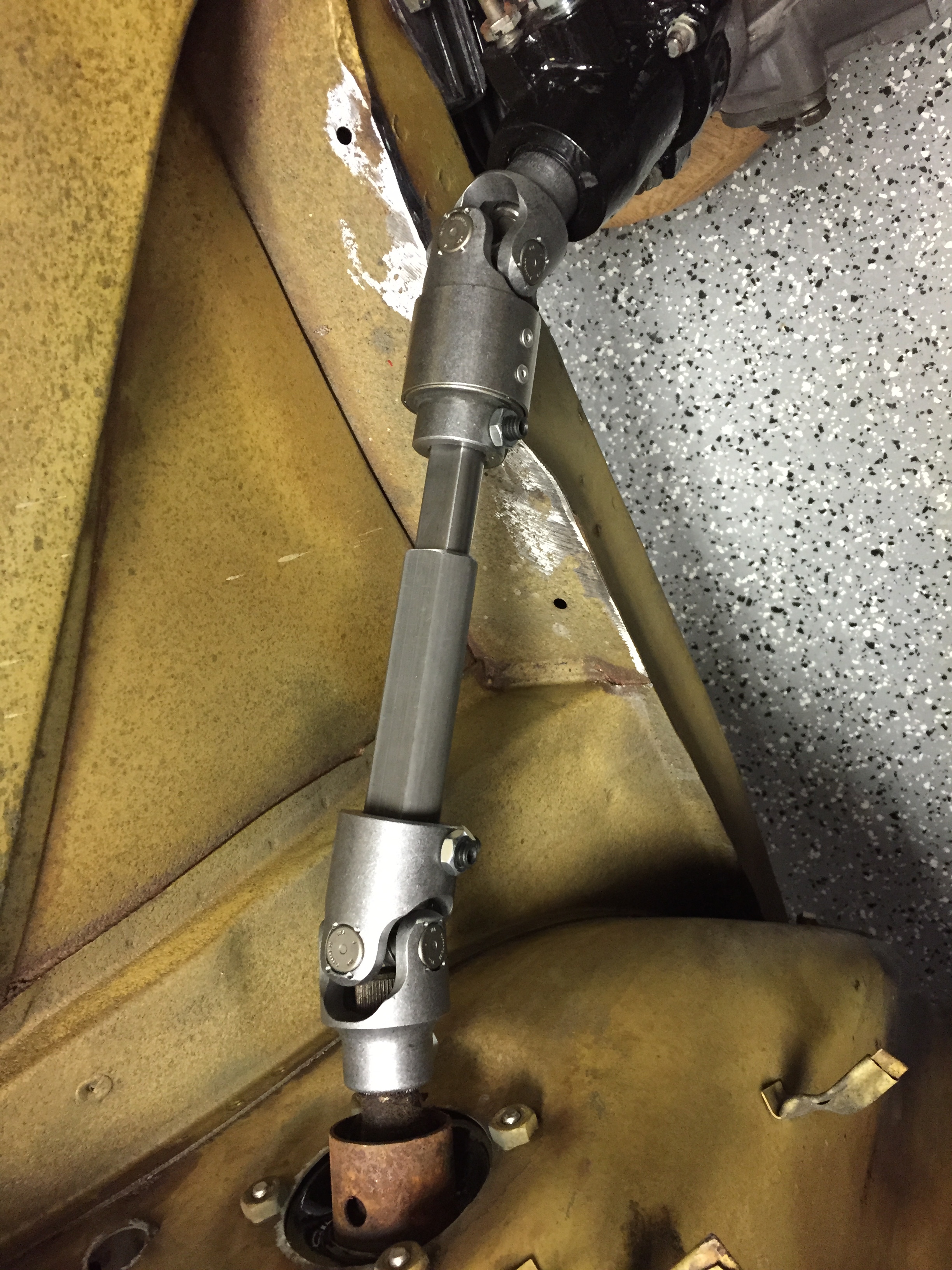
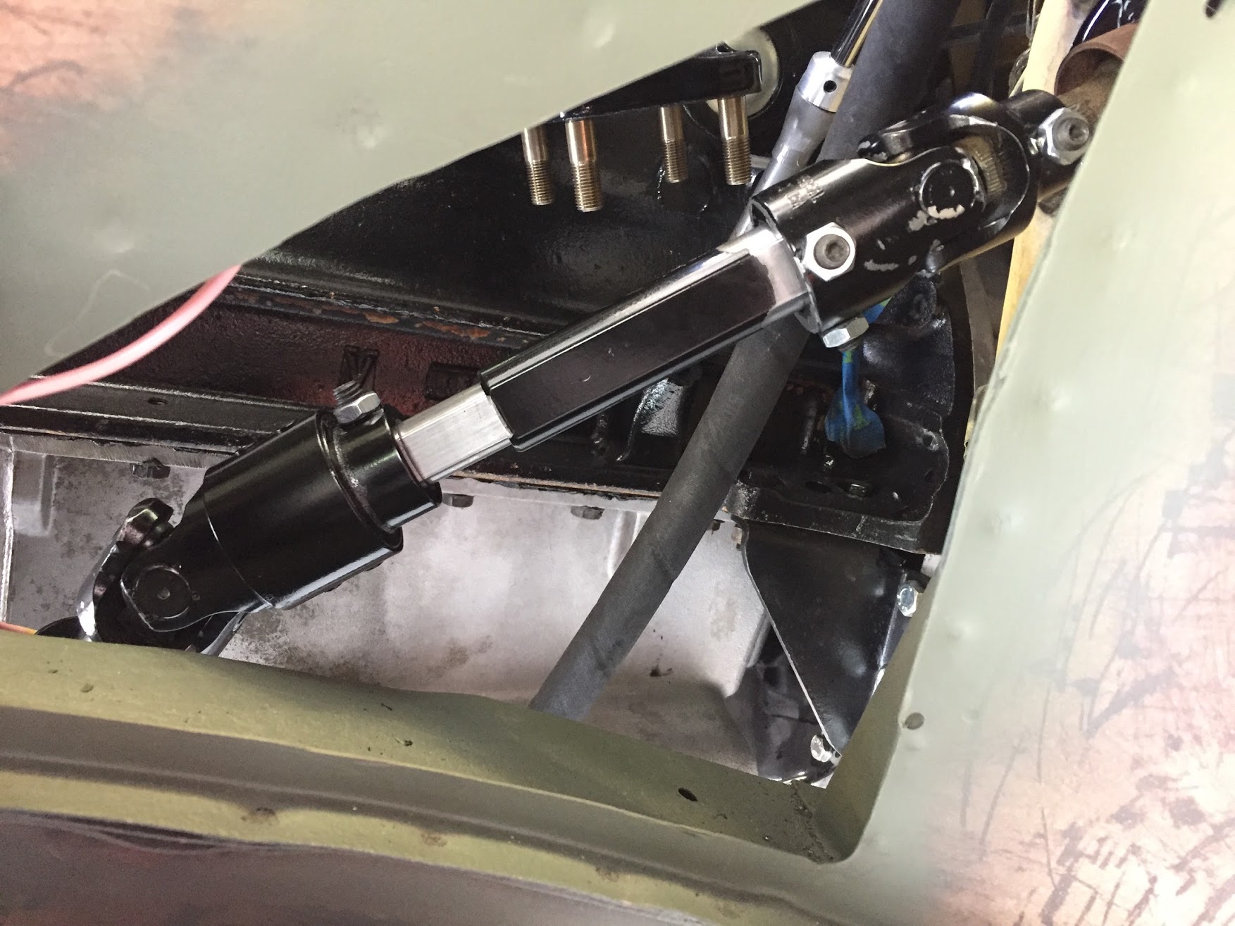
The instructions included with the M&C Wilkinson rack and pinion kit advise that a small curved section of the LH from rail should be relieved to make room for the knuckle of the new lower universal joint. After fitting the rack with the lower joint in place I was able to mark the rail and use a grinder to remove some of the surface. I will re-weld the frame joint before bodywork just to make sure that it is sufficiently closed to moisture. The cut out can be seen in the images below. It may appear that the UJ joint is making contact with the frame rail, but it does not.
My thanks to Richard Oliphant and the GT6Steve for sharing parts numbers for the components needed to assemble the new steering shaft. In my case, the spline count on the steering column and on the rack were the same at 3/4″-48. These should be checked before ordering parts.
Borgeson part numbers:
1- 409418 3/4” DD Shaft, 18” long
1- 409536 1” DD Tube, 36” long
1- 034937 Vibration U joint, Steel, 3/4”DD x 3/4”-48
1- 015237 U joint, 1” DD x 3/4”-48
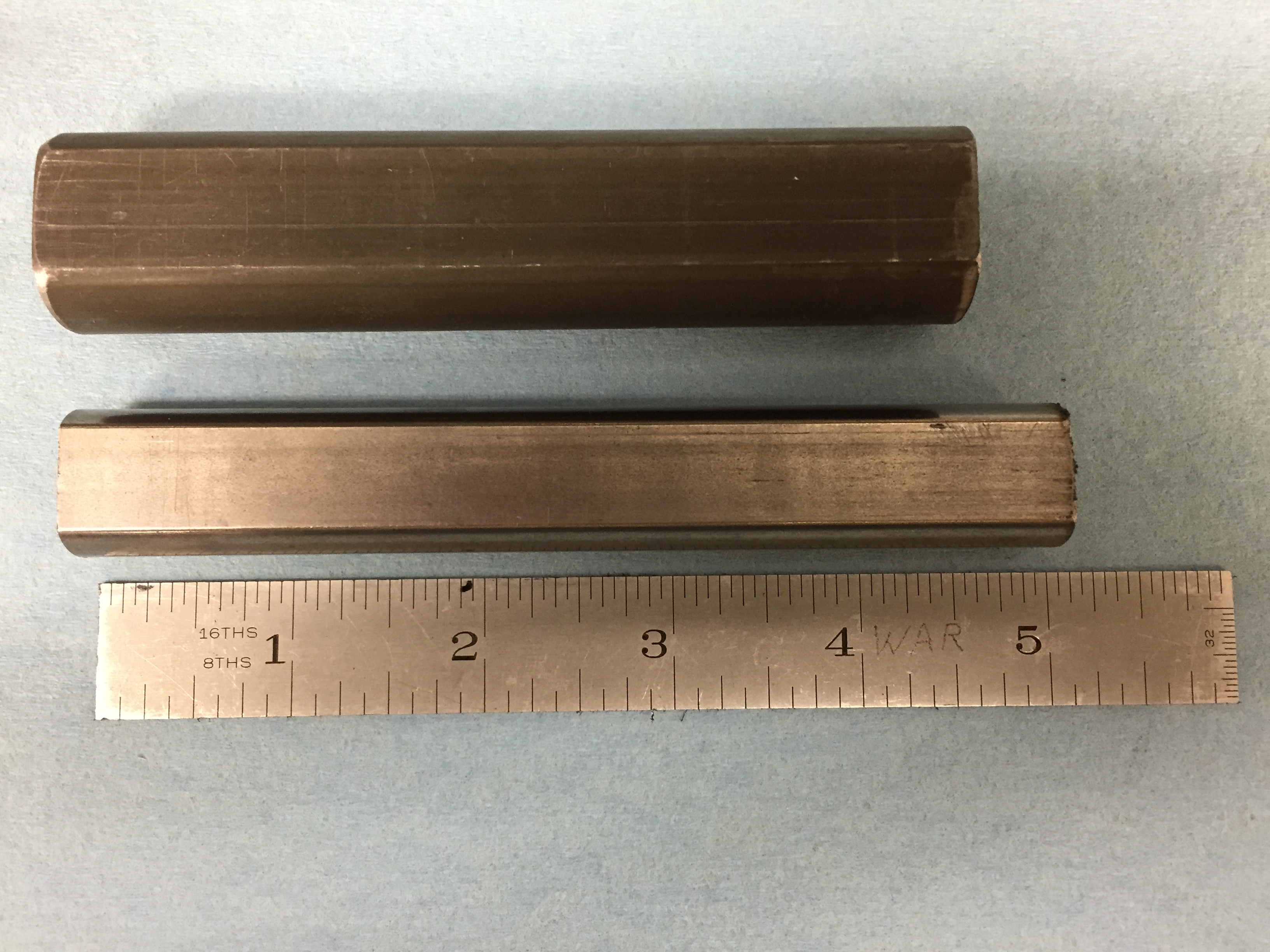
The 3/4” DD shaft slides part way into the 1” DD tube, these come long and have to be cut to fit. For my particular installation I used a 5″ tube and a 4 1/2″ shaft. I used a 1/2″ square wooden dowel to determine optimal shaft length.
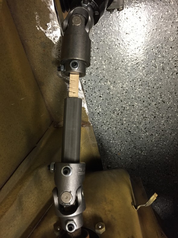
Trial Fitting Steering Linkage
Others undertaking this project should measure for their own circumstance.This provides some play to both remove the lower column and also some collapse or crush distance. As Richard stated, “Leave enough free play in shaft so you can slip universal joints off without having to loosen up steering column.”
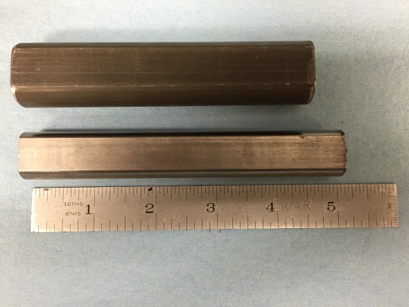
Tube and Shaft Cut to Fit

New Linkage Test Fitting

New Linkage Test Fitting
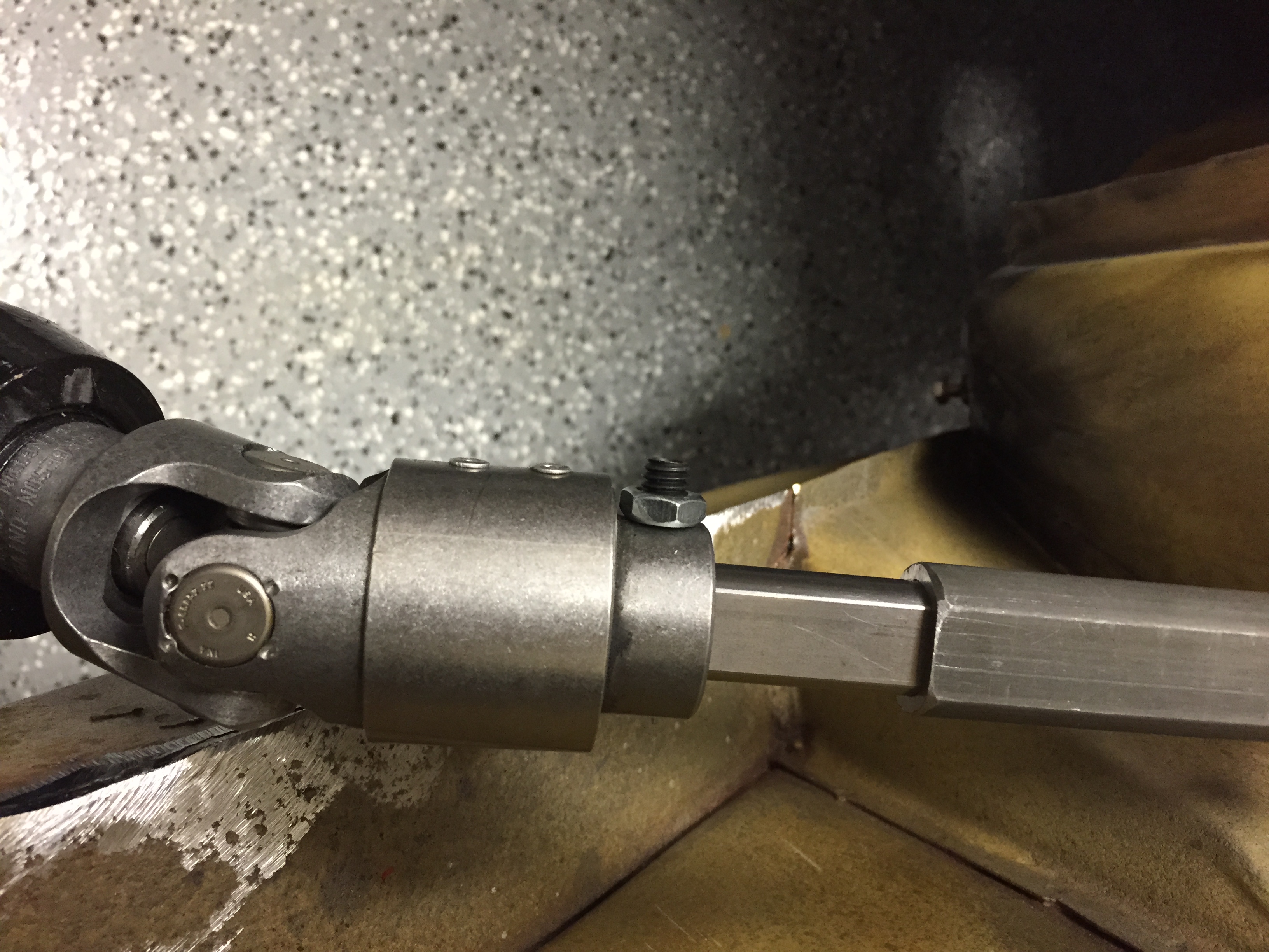
Borgeson instructions direct that in attaching the U-joint to the 1″ Double D tube the tube should be fully pushed on to the u-joint. Then tighten the short set sure to secure the joint in the tube. Mark the position of the other set screw on the tube. Remove the u-joint. Drill a 3/8″ hole at the point marked on the tube through ONE WALL OF THE TUBE ONLY. Re-install u-joint and set screws. The long set screw should pass through the drilled hole and bear against the opposite wall of the tubing. Tighten both set screws and lock nuts. Check and retighten all set screws and lock nuts.
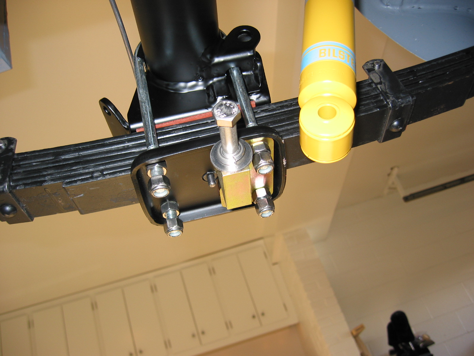
Fitting of the Electric/Hydraulic Pump
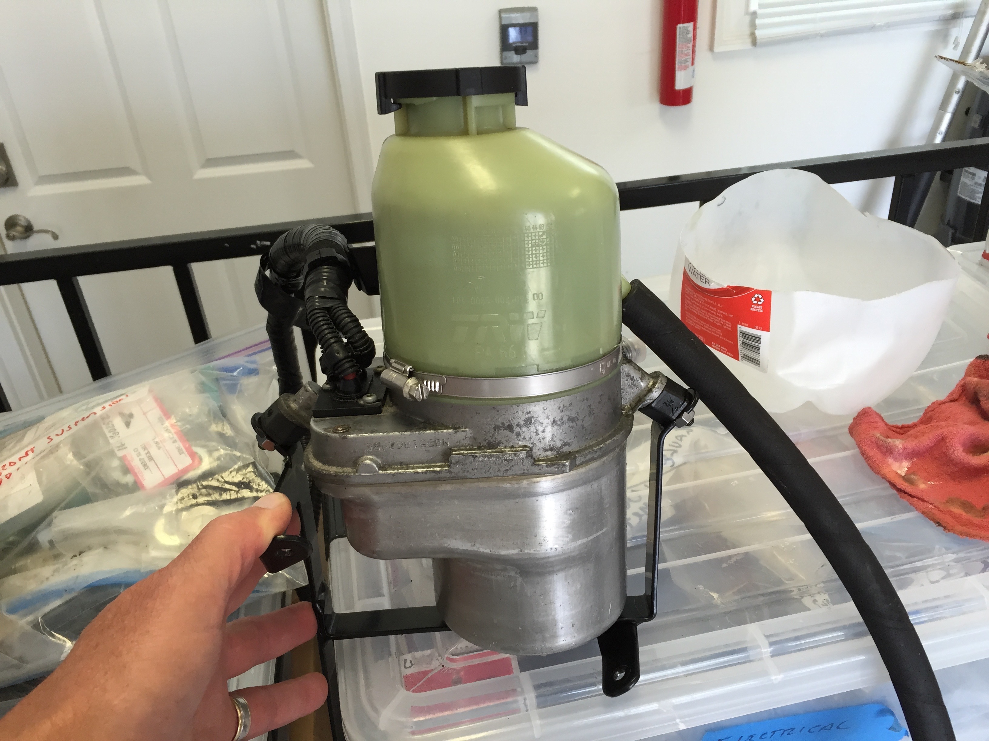
The M&C wilkinson kit provides a bespoke pump mounting bracket and a combined pump/reservoir. I am not sure of the source of the pump. The pump attaches to the bracket at three mounting points where 1/4″-28 nuts and shockproof washers are used to secure the components. The supplied instructions provide directions on the location of the bracket on the LH engine bay valance. Time should be spent on locating the bracket. There is very little available room as the brake fluid reservoir, the master cylinder, and the fuse panel all compete for space. Attention should be given to allowing sufficient space for the pumps hydraulic hose fittings.
The pump is heavy and I found that it should be fixed to the bracket before the bracket is fit to the car in order to mark the locations for the holes to be drilled for the bracket mounting to the car. With the weight of the pump the feet of the bracket spread slightly.
Fastening hardware was supplied with the kit; however, I decide to use my own stainless fasteners. The two bracket fixing points to the diagonal frame brace are secured with self-tapping sheet metal screws while the bracket leg that fastens to the valance wall is secured with a #10 -32 x 1/2″ hex head machine screw, flat washer and nylock nut.
This is the pump and its mounting bracket:

Power Steering Pump & Bracket
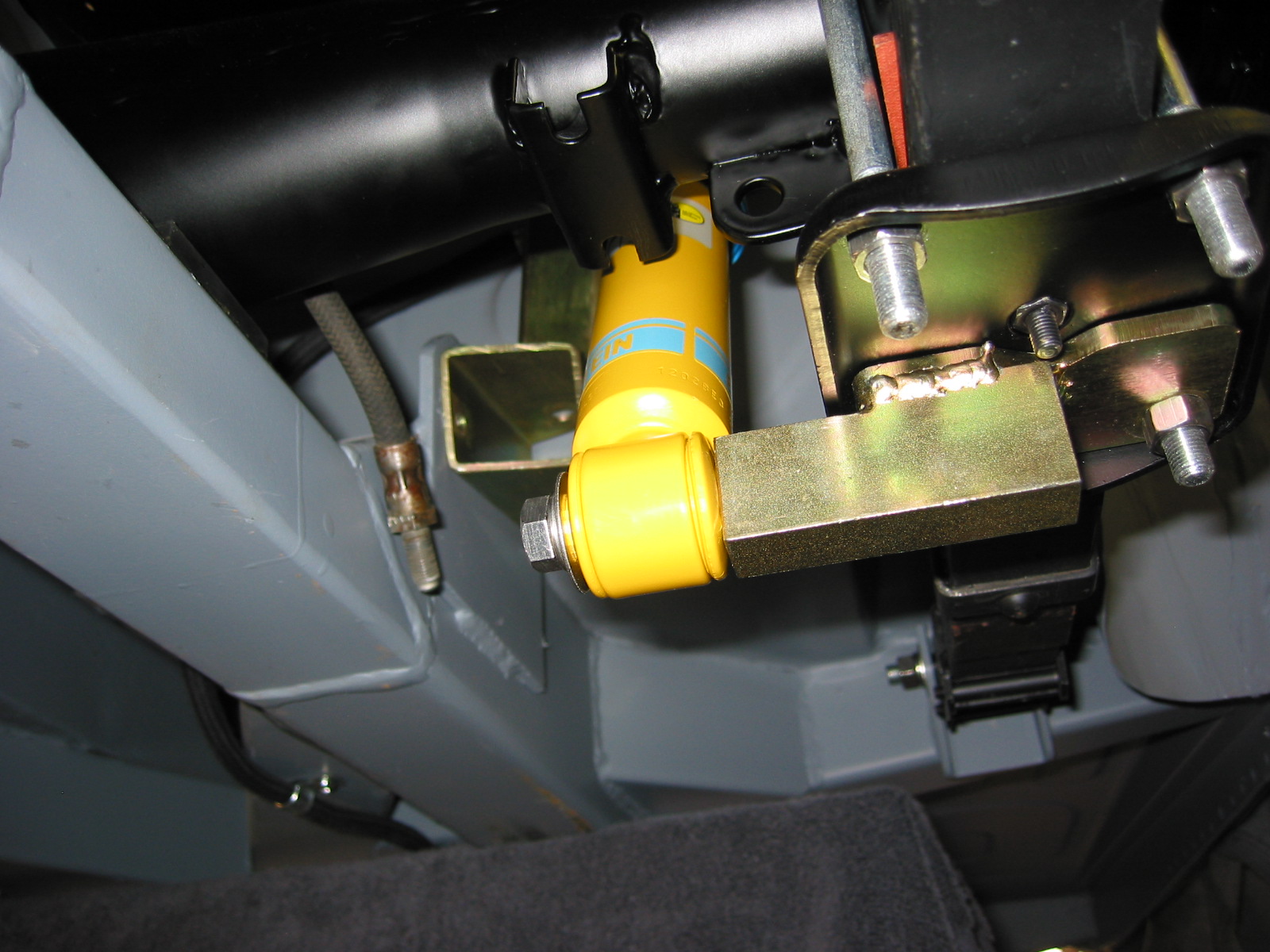
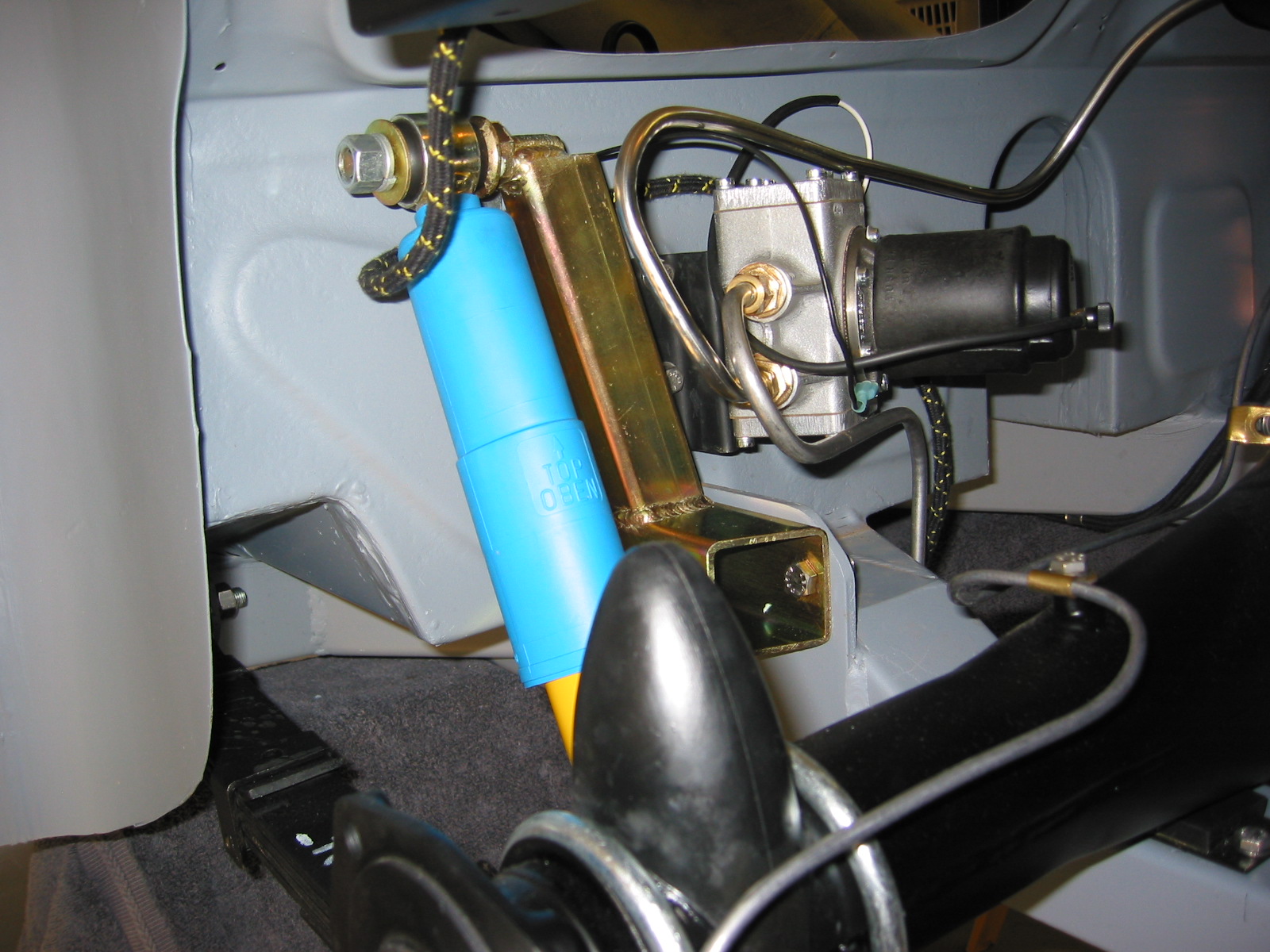
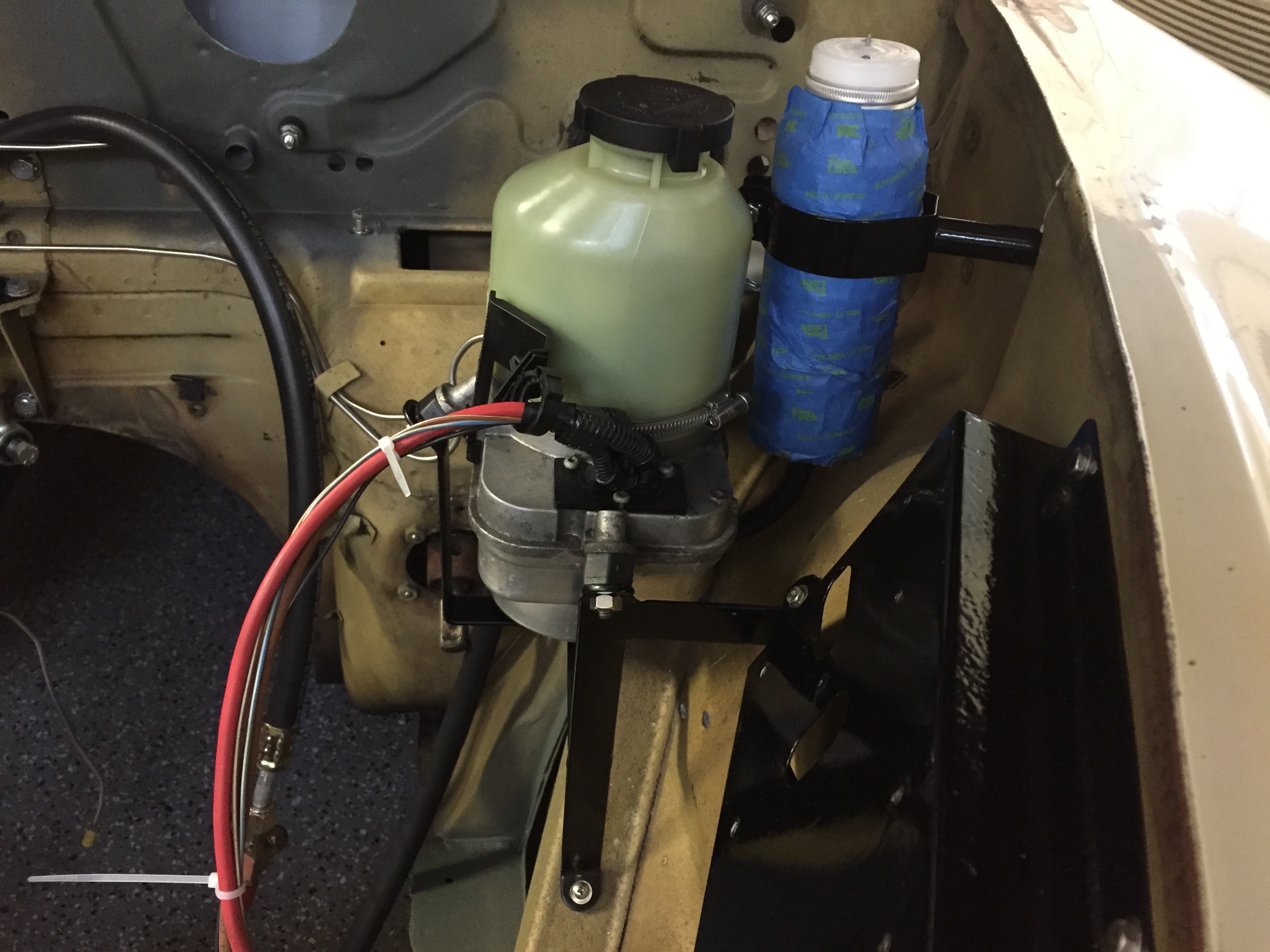
The images below show the final location and mounting of the pump/reservoir and its bracket:
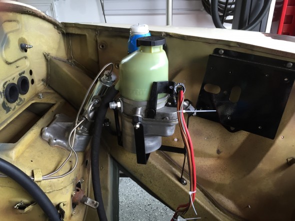
Power Steering Pump & Bracket Installed
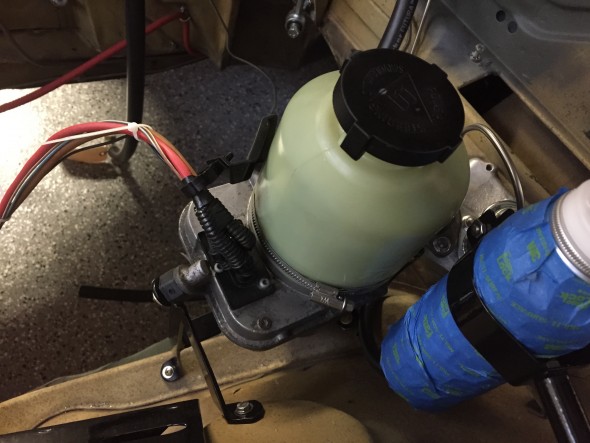
Power Steering Pump & Bracket Installed

Power Steering Pump & Bracket Installed
With the heater box, hydraulic fluid reservoir, considerable wiring, and the power steering pump itself, there are very tight quarters for the pumps’ two hoses and the heater hoses/pipes. After some manipulation I was able to get everything mounted without location conflicts.
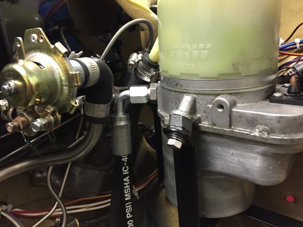
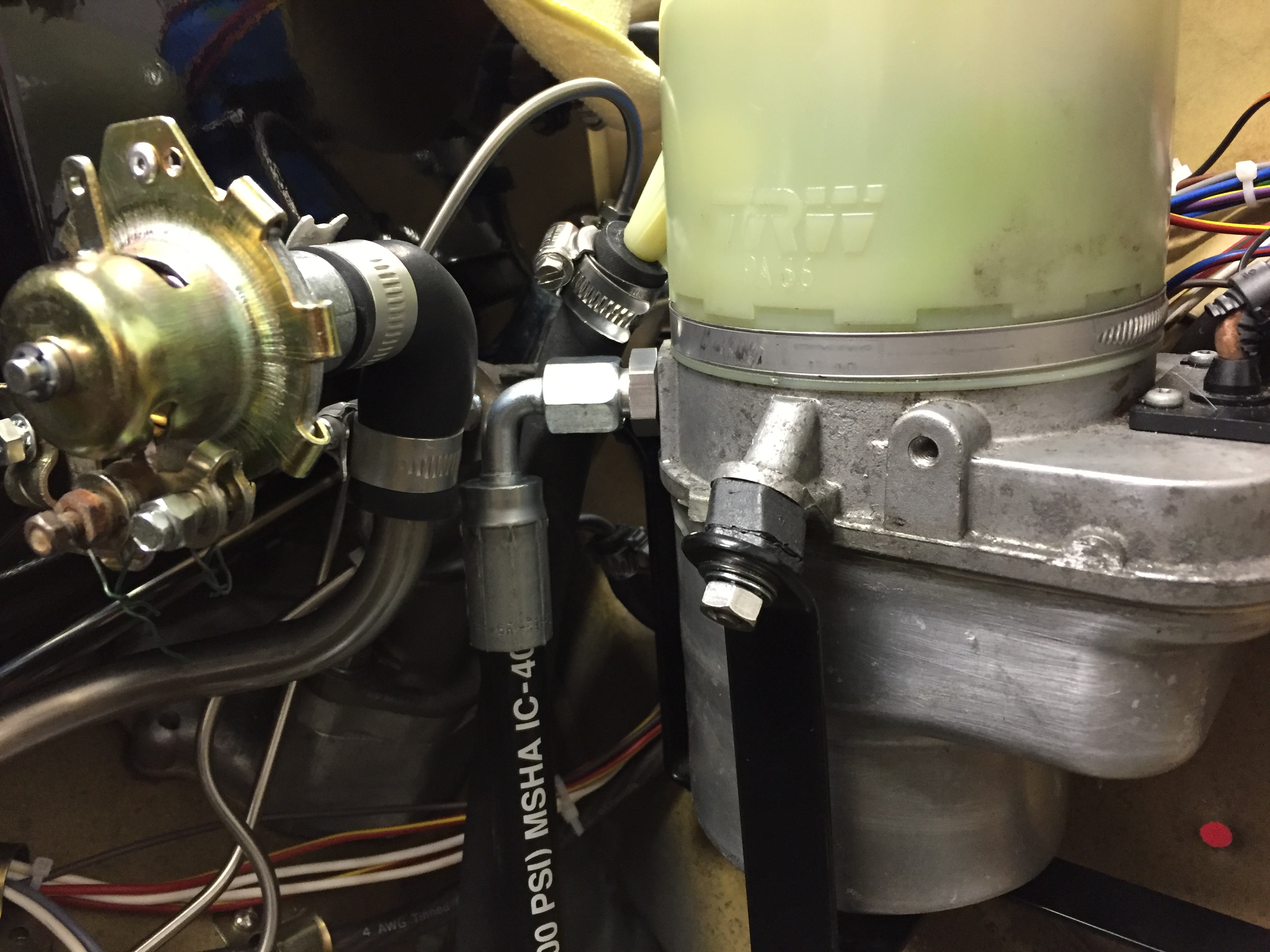
Power Steering Pump Hydrualic Hoses
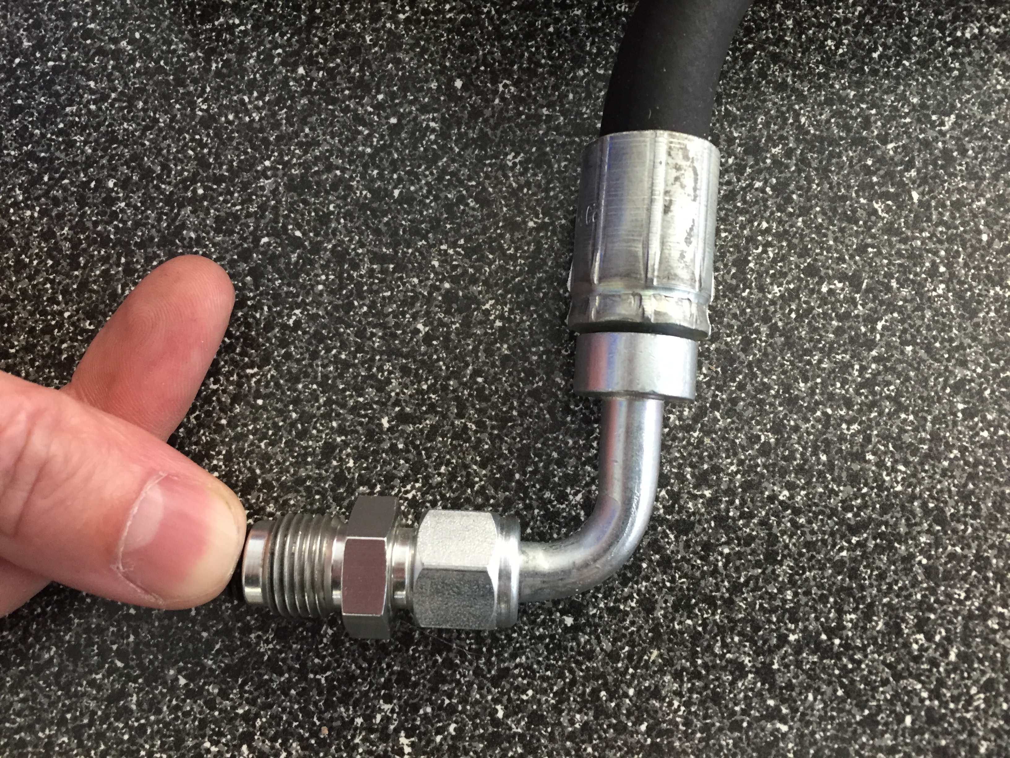
The M & C Wilkinson kit supplied the hydraulic hoses and fittings, but to save some critical room I used a different -6 ninety degree fitting for the high pressure hose and purchased a new hose that will be cut to length after the steering rack is installed in the car. I will also include thermal sleeving on the hoses to protect them from the exhaust temperatures.

-6 90 Degree Fitting on the High Pressure Hose
Electrical Requirements and Wiring
The electrical wiring of the power steering pump is addressed in the “Building a New Wiring Harness” post.
Trial Fitting
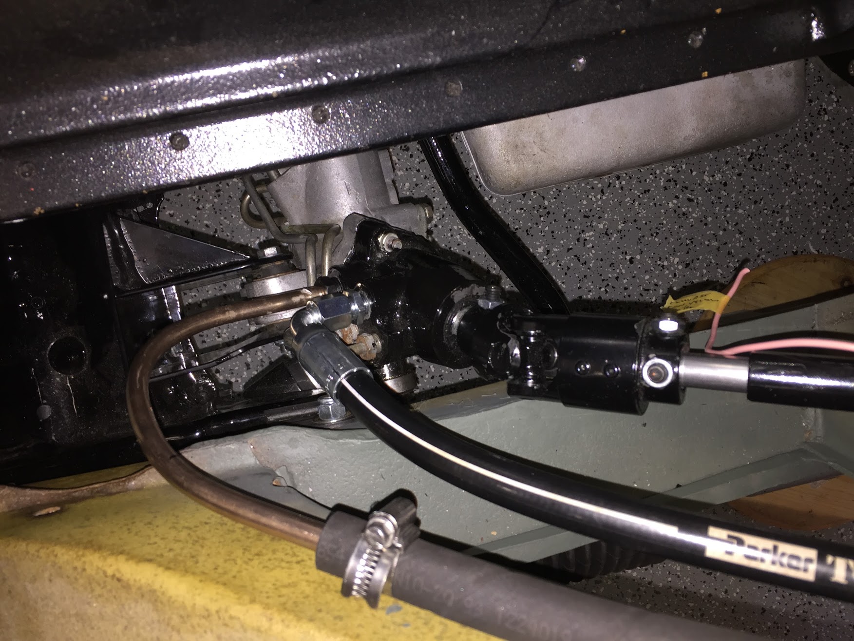
In May/June 2017 I installed the front suspension crossmember as described in the Front Suspension website entry. Once installed with the steering rack I was able to finish the hydraulic plumbing. I used another -6 90 degree fitting at the steering rack end of the high pressure hose after cutting the hose to the proper length. I had an hydraulic hose shop do the crimping for me.
On the low pressure side of things, I decided to use a hard line with a gentle sweep (this allows more room for ease of mounting) and secured it to the low pressure hose provided in the M&C Wilkinson kit. Both ends of this hose were secured with Jubilee hose clamps.
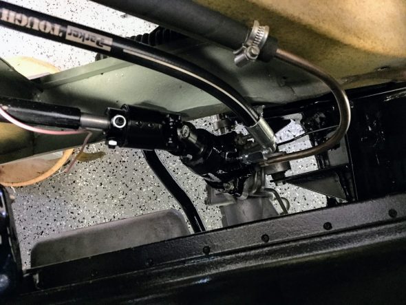
Steering Hydraulic Lines Installed

Steering Hydraulic Lines Installed
Final adjustments were made in the steering linkage and all of the set screws and locking nuts were tightened.

Final Adjustment of the steering linkage