February 2, 2003
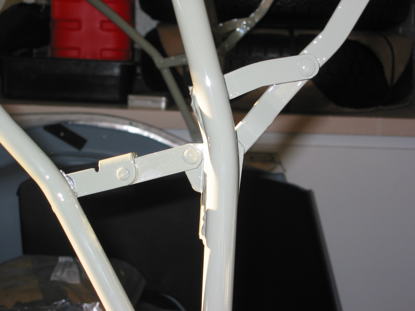
Front Suspension Components.
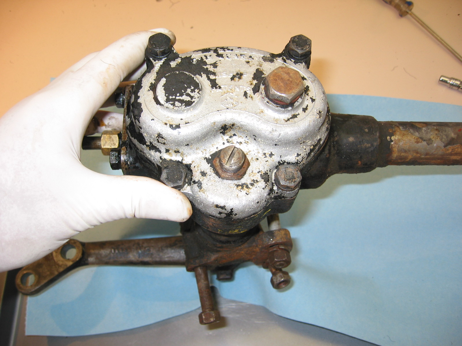
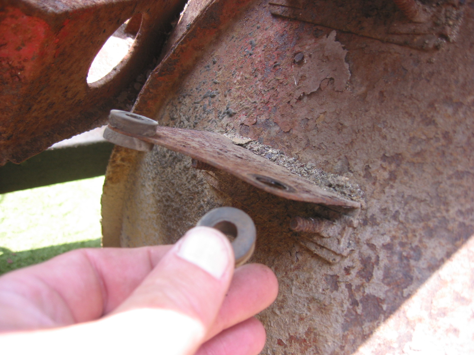
Removed the steering arm by loosening two 11/16” nuts with tab washer connector flattened. Note that the steering arm angles toward the dustshield – not the motor.

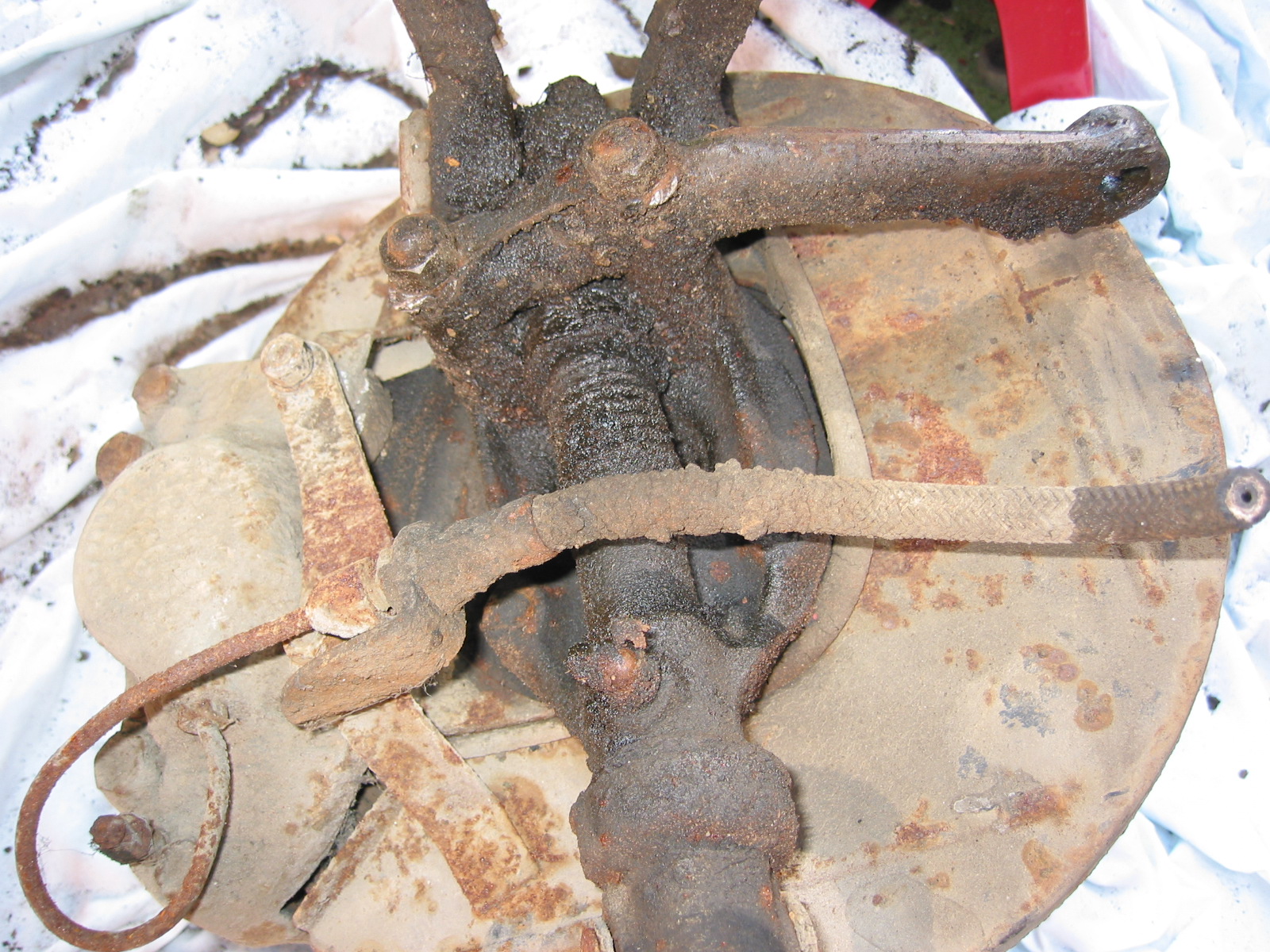
Stub Axle Carrier, King Pin, Caliper, Dust Shield
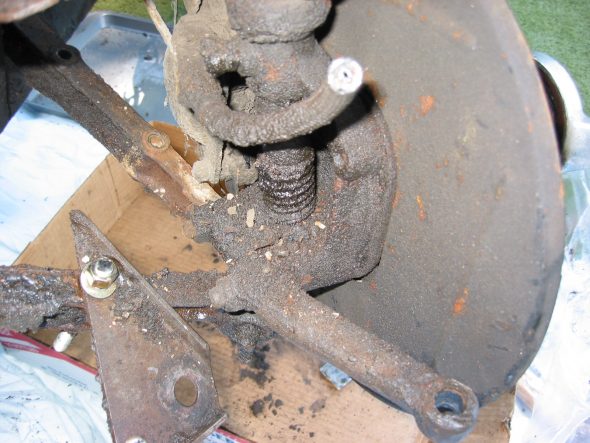
Stub Axle Carrier, King pin, Dust Shield
Brake Caliper – Removed by first unscrewing the brake pipe union. Remove two nuts securing the brake hose support bracket. Remove bracket. Unscrew two caliper retaining bolts.
Removed two rubber bushings from the upper trunnion.
Swivel Pin – Removed split pin at the swivel pin nut and tap swivel pin out with hammer.
Loosen cotter on the swivel pin and retract. Loosen two large nuts (bushings) on “A” arms and remove. Pull out pin and remove “A” arms.
Grease Cup – Pulled out grease cup from hub – fabricated tool with long manifold nut and 5/16” x 3” bolt and the slide hammer.
Straighten and retract split pin on castle nut through the hole in the splines on the hub. Not easy to do!!
Remove castle nut. Brake rotor and hub then lift off of the dust shield and spindle.
From the swivel axle spindle removed the dust cover spring and upper and lower dust covers. Separated the rotor from the hub. 4 bolts – 2 long ones hold the brake caliper and bracket. 2 short bolts hold the plate to the swivel axle.
Removed rubber “U” seal from around the dust shield opening for the swivel axle.
March 12, 2003
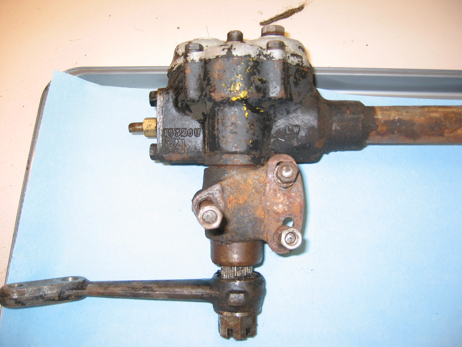
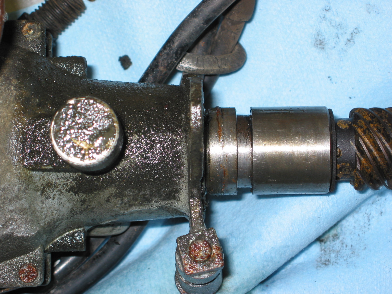
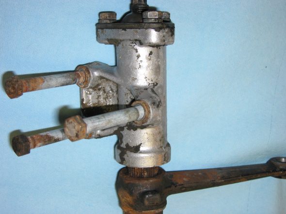
Steering Idler and Steering Box
The steering idler and steering box are next for cleanup. I will have these rebuilt by someone who knows what they are doing. Probably Bruce Phillips at Healey Surgeons.
Steering Idler 2
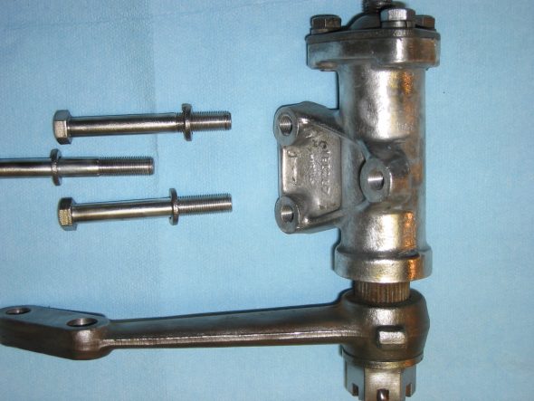
Steering Idler Clean
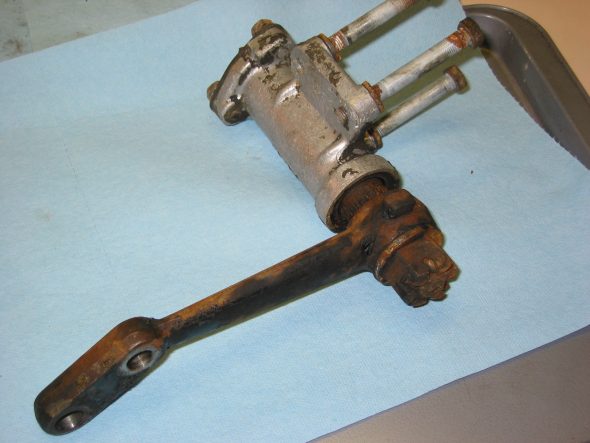
Steering idler 3
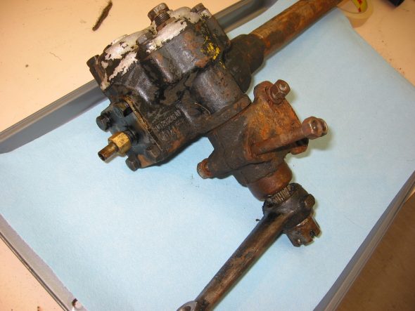
Steering Box 6
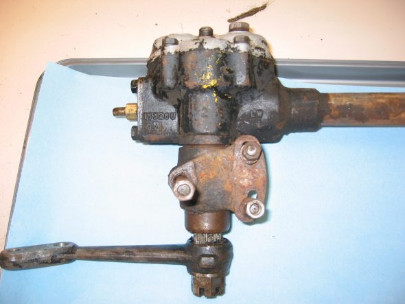
Steering Box 5

Steering Box 7
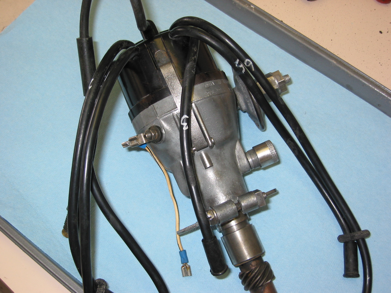
Distributor
The distributor was also in good shape and easy to clean. We may still switch to an electronic unit, but cleaned up the Lucas just in case.
Distributor 7
Distributor 8

Distributor 9

Distributor Clean
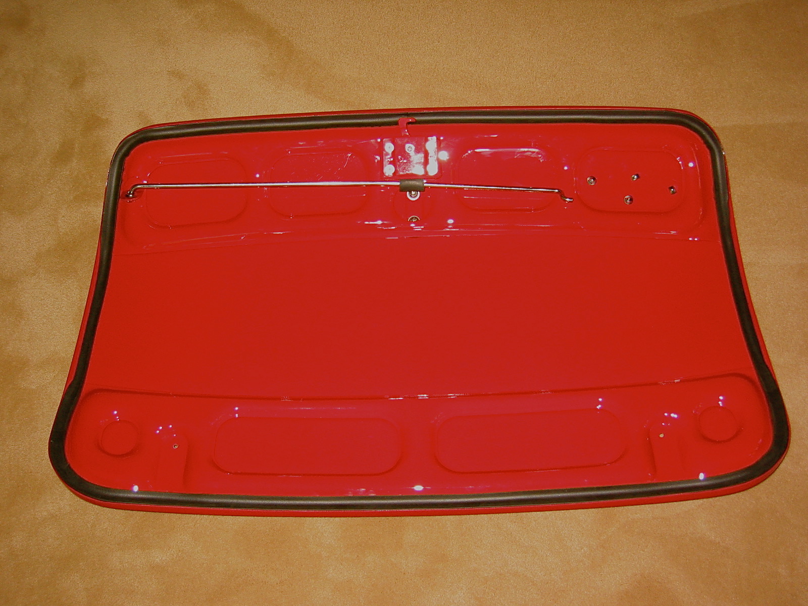
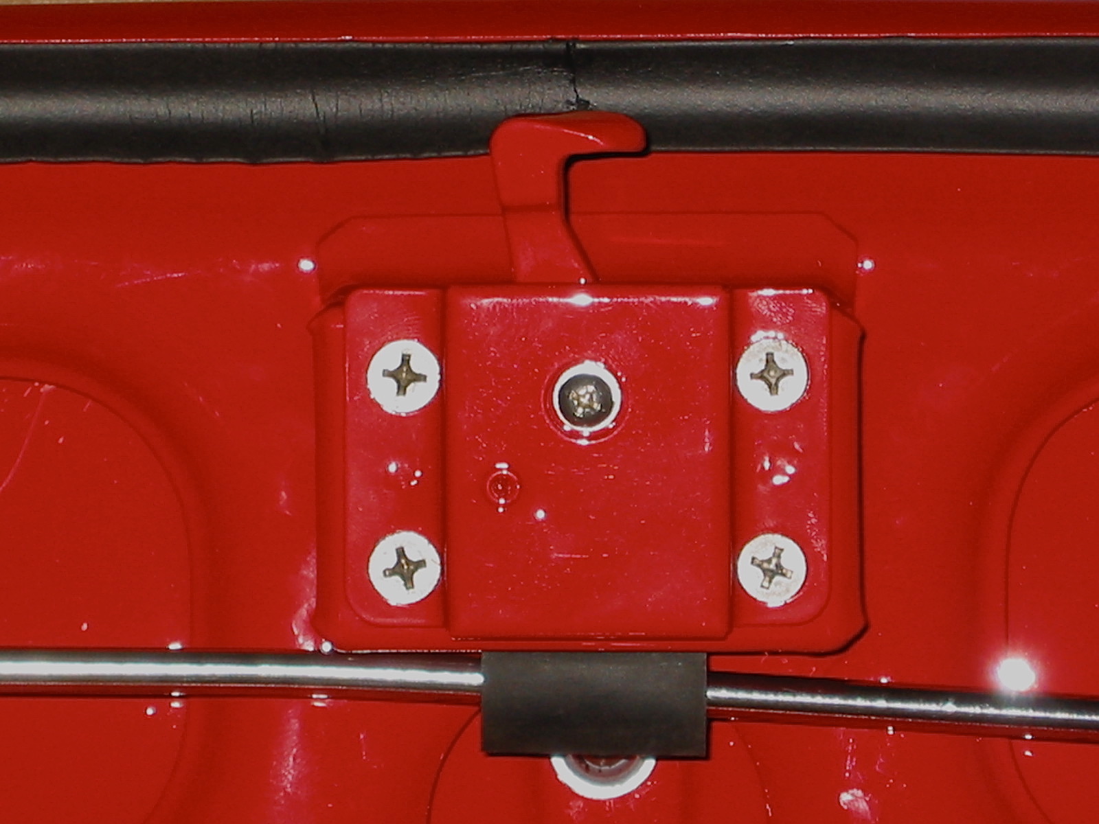
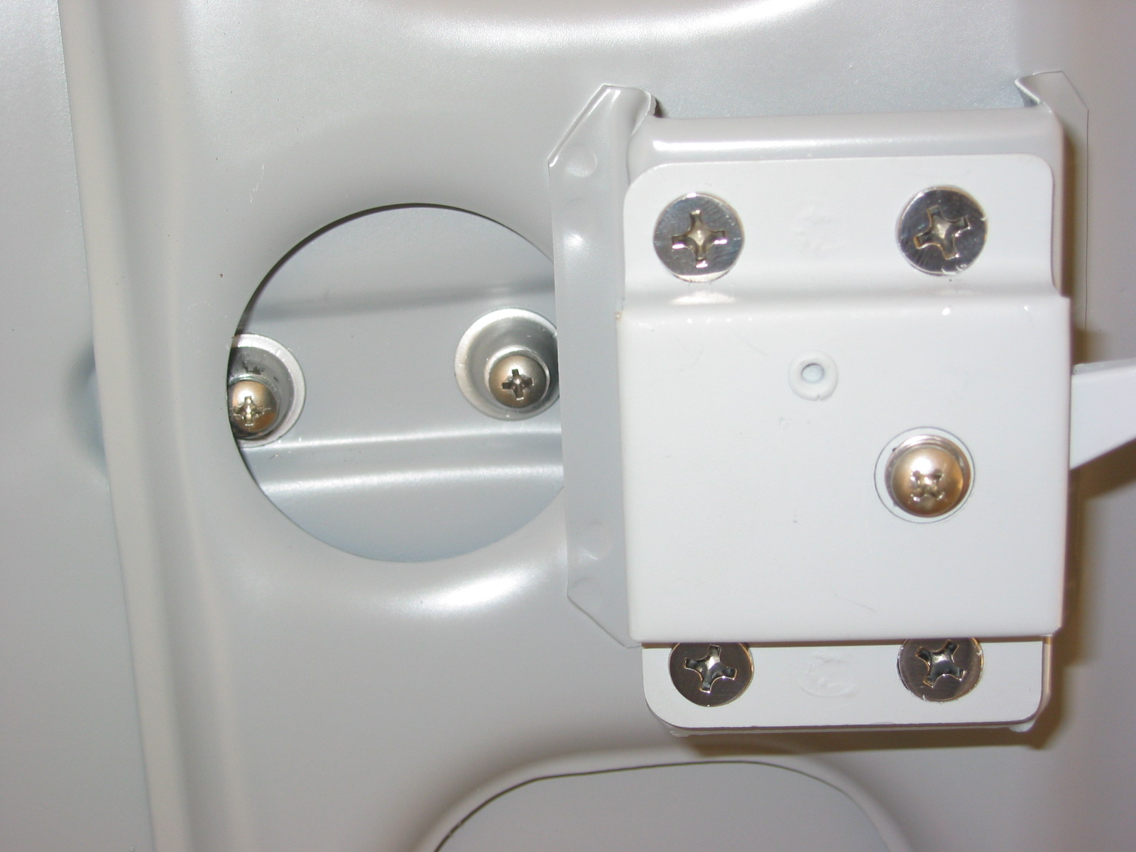
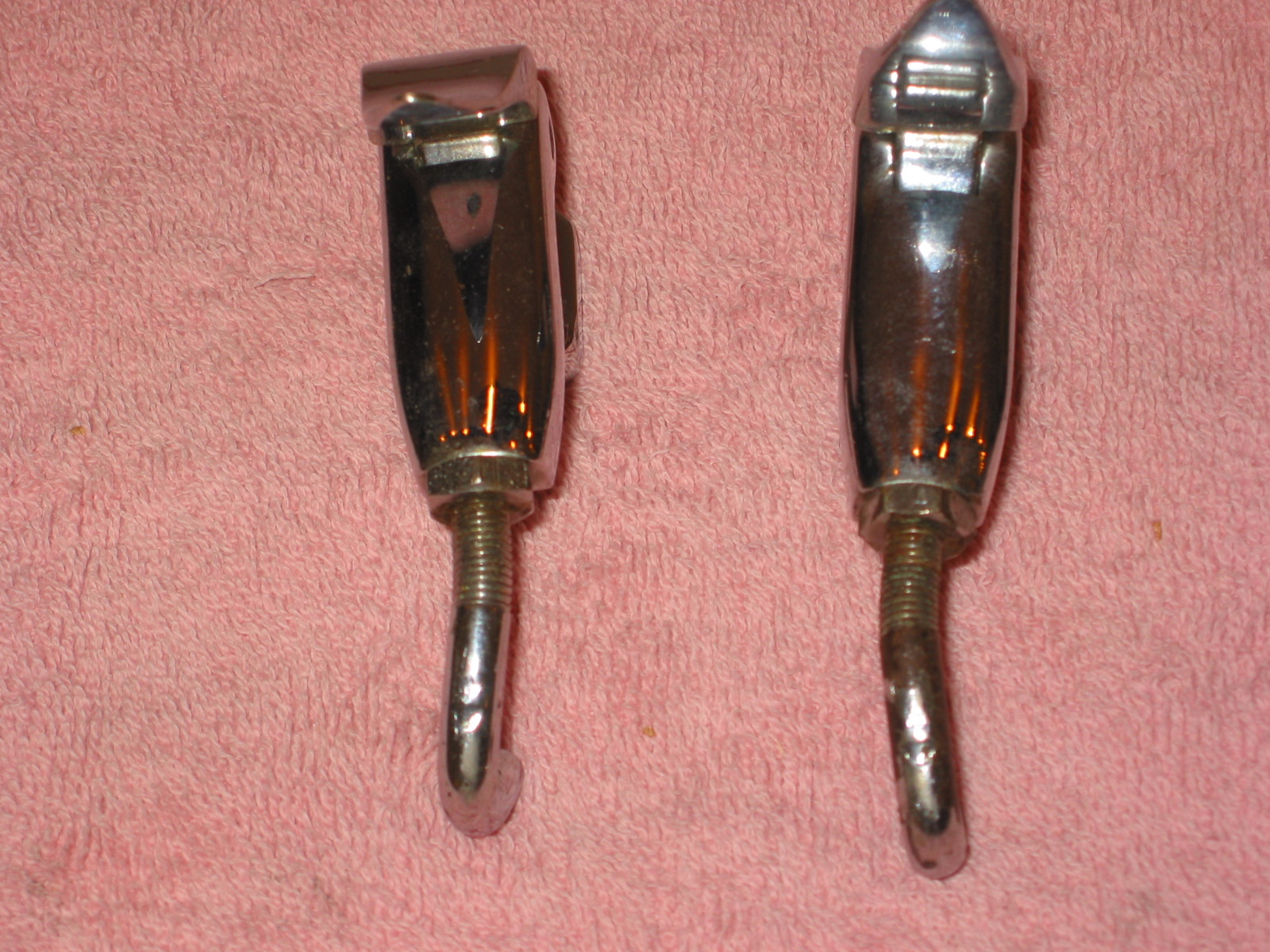
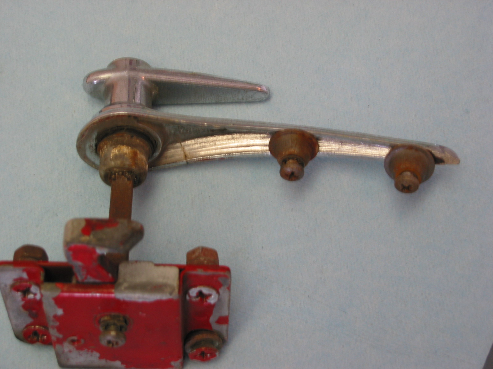
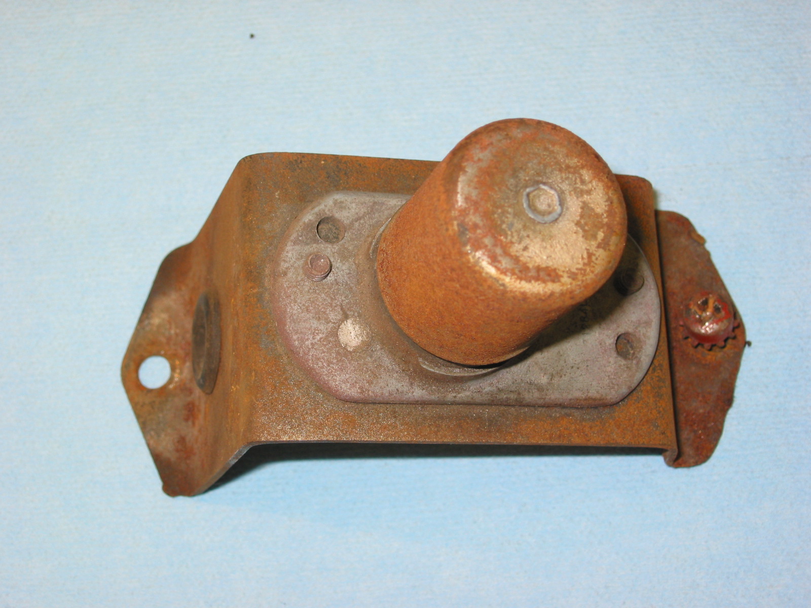
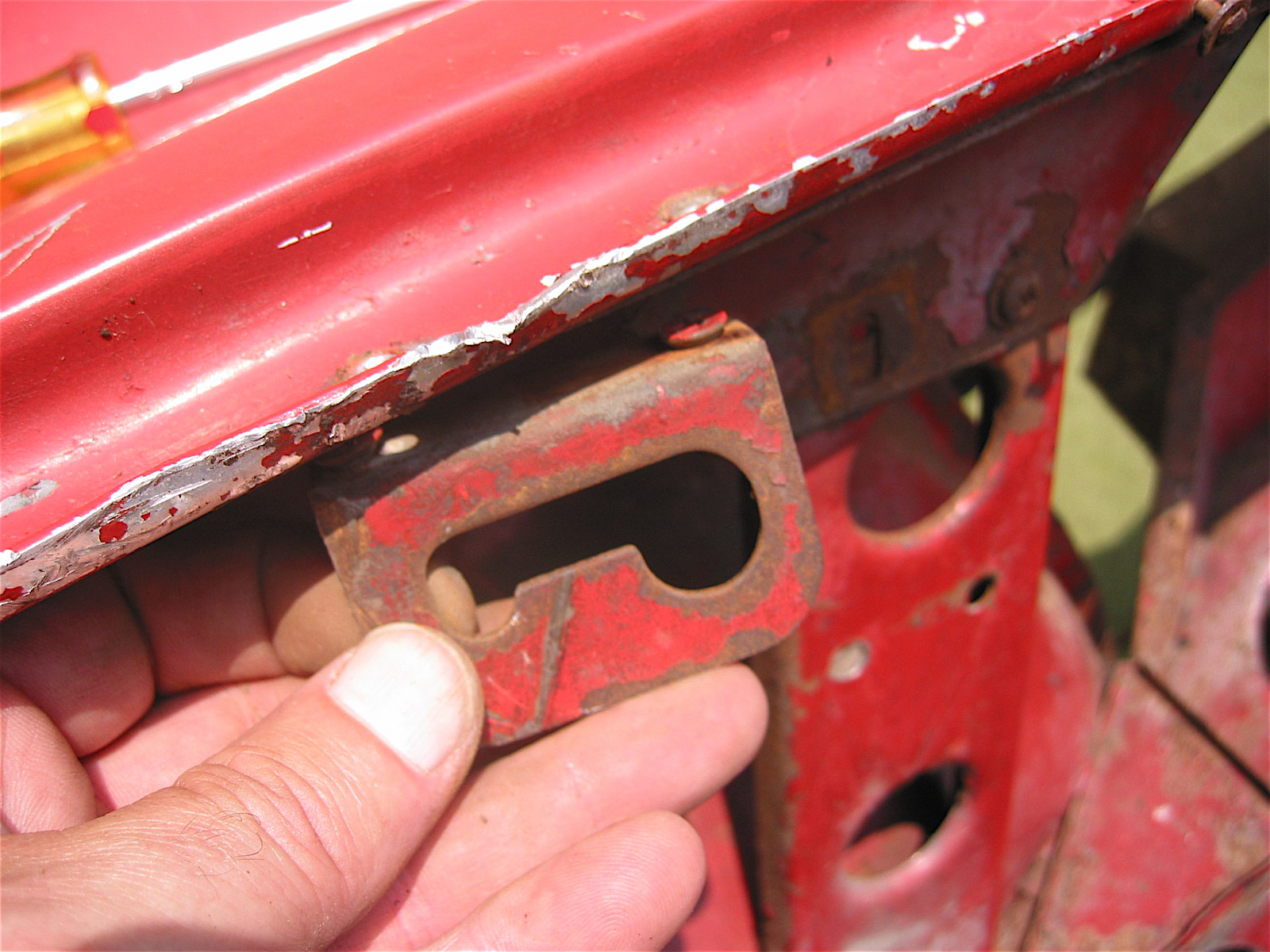
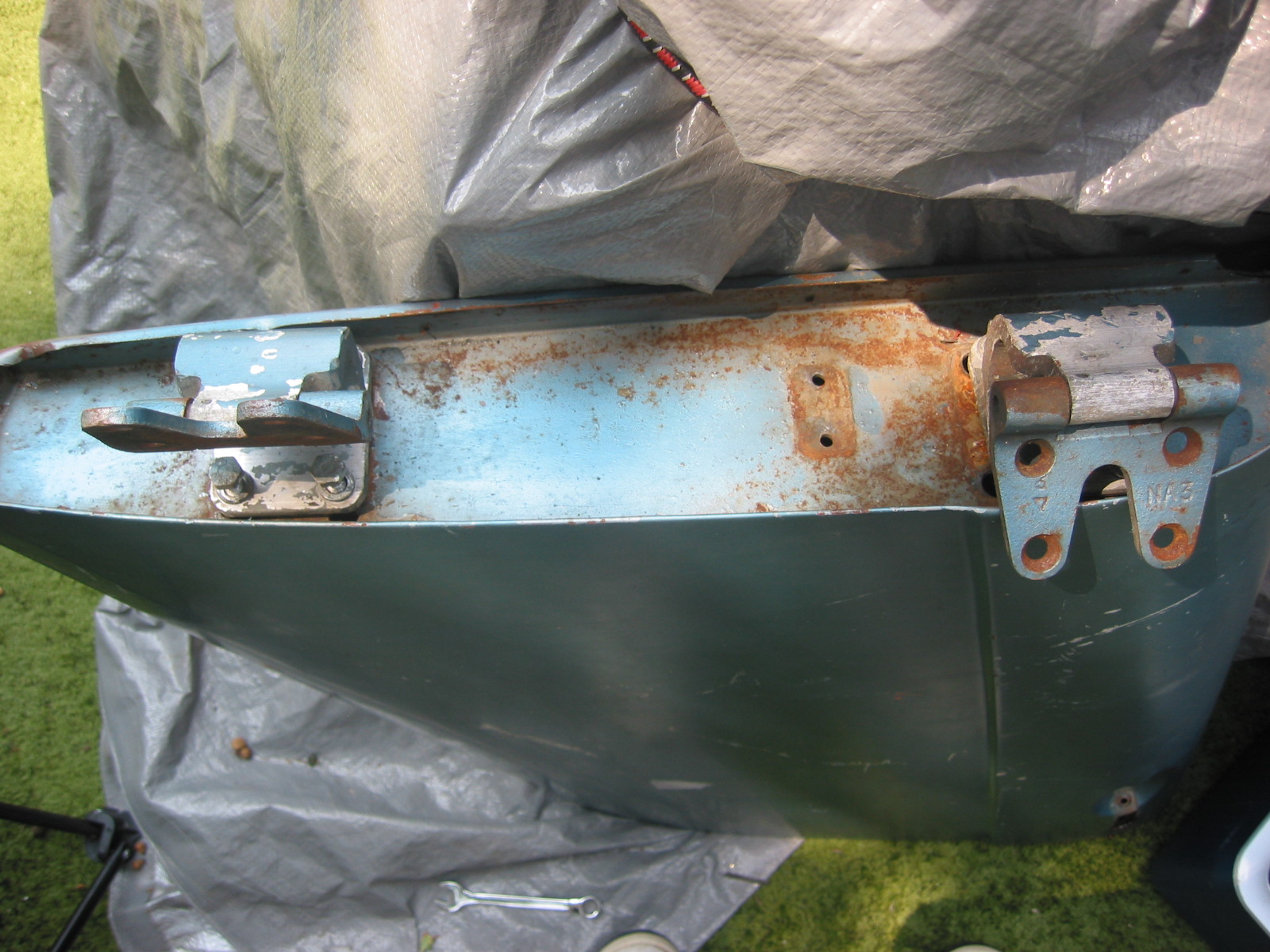
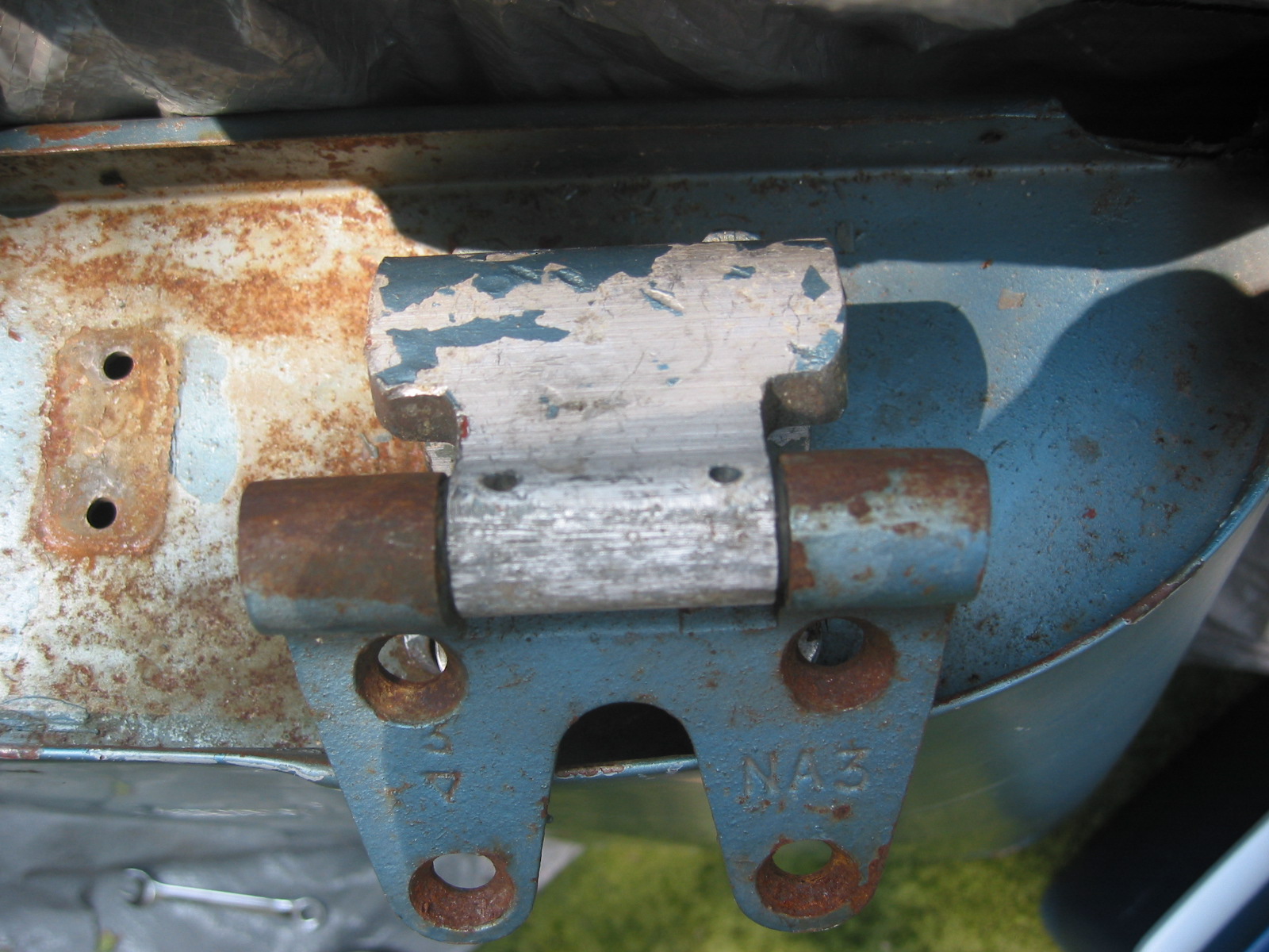
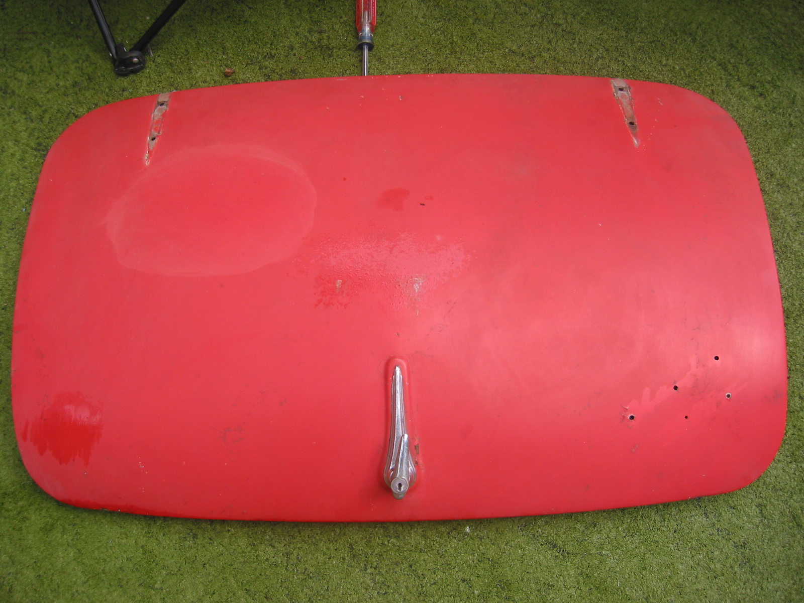
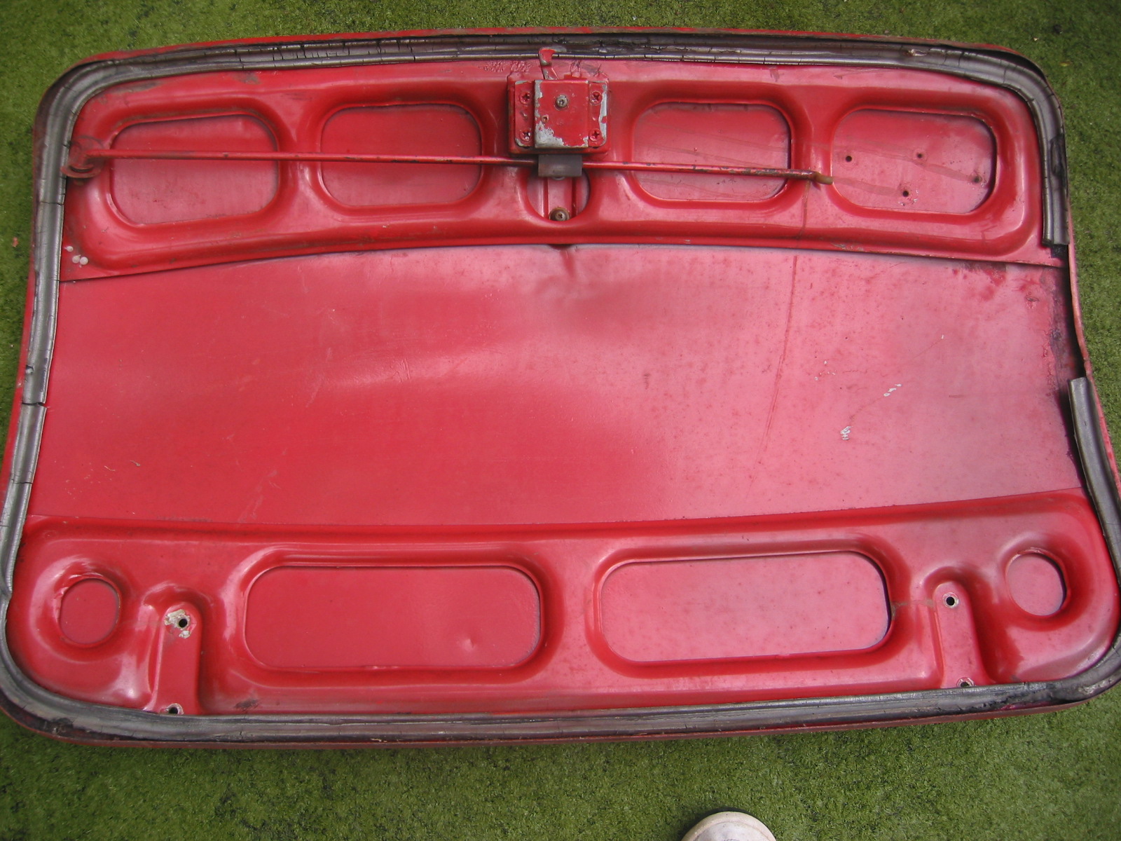
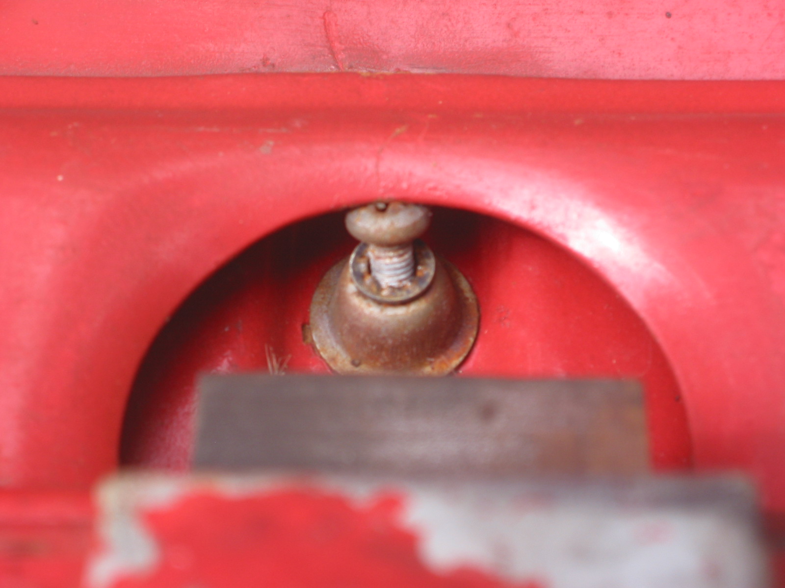
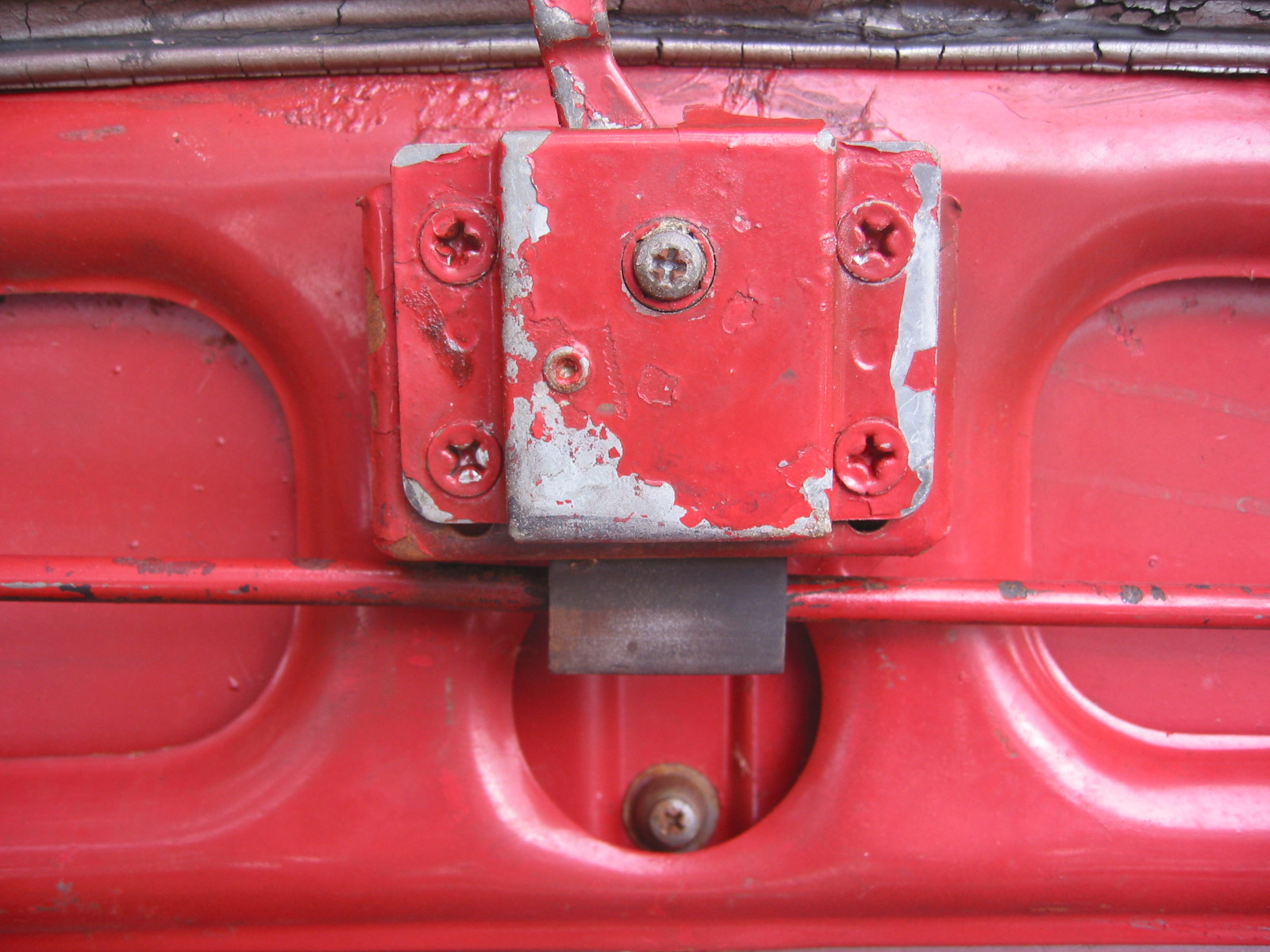
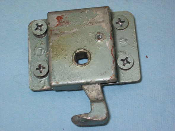
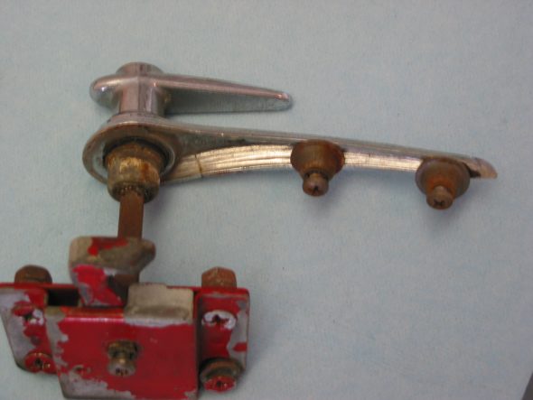
Boot Latch and Lock Assembly
The boot latch and lock assembly was in reasonable shape but the chrome will have to be replaced as it is cracked rather badly.
Boot Lock
Boot Handle & Lock
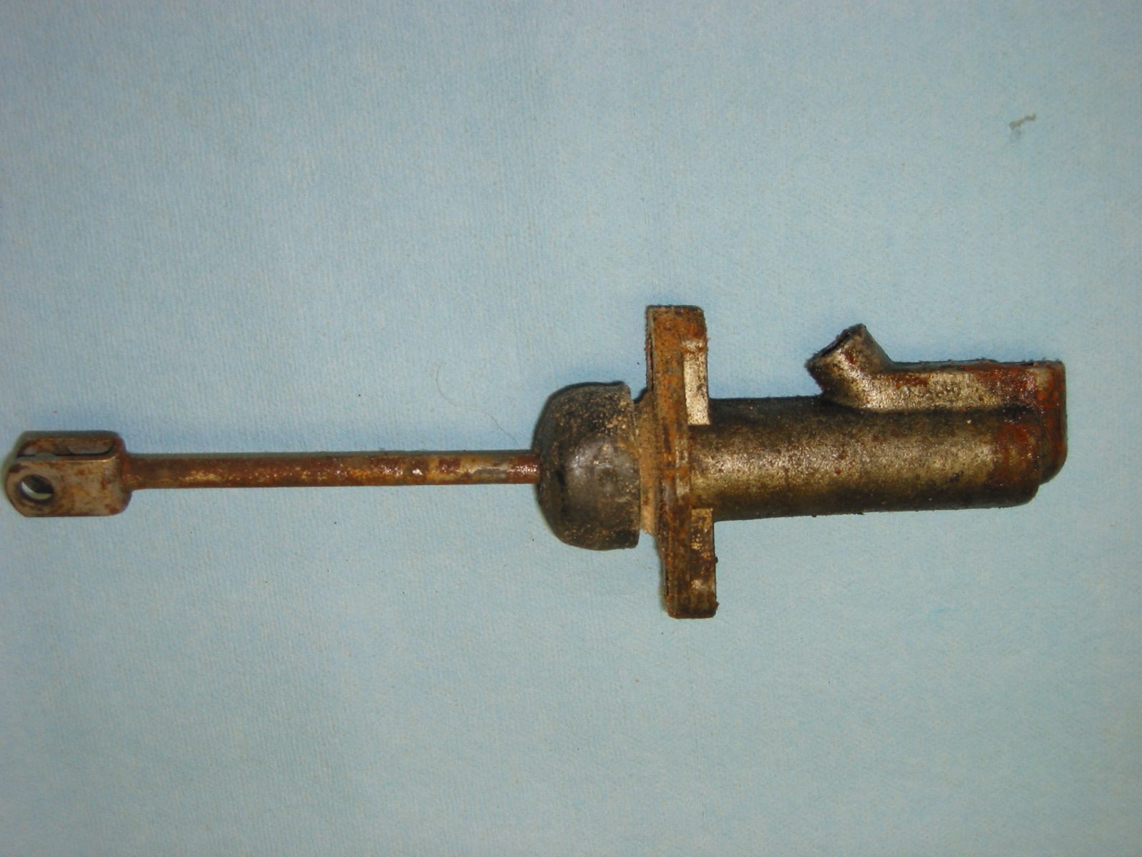
Master and Slave Cylinders
The clutch master and slave cylinder will both be replaced with new items.
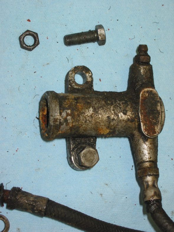
Clutch Slave Cylinder
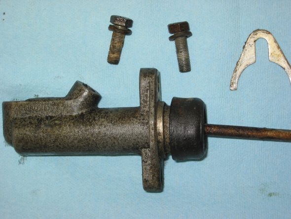
Clutch Master Cylinder with aluminum spacers

Master Cylinder Brake
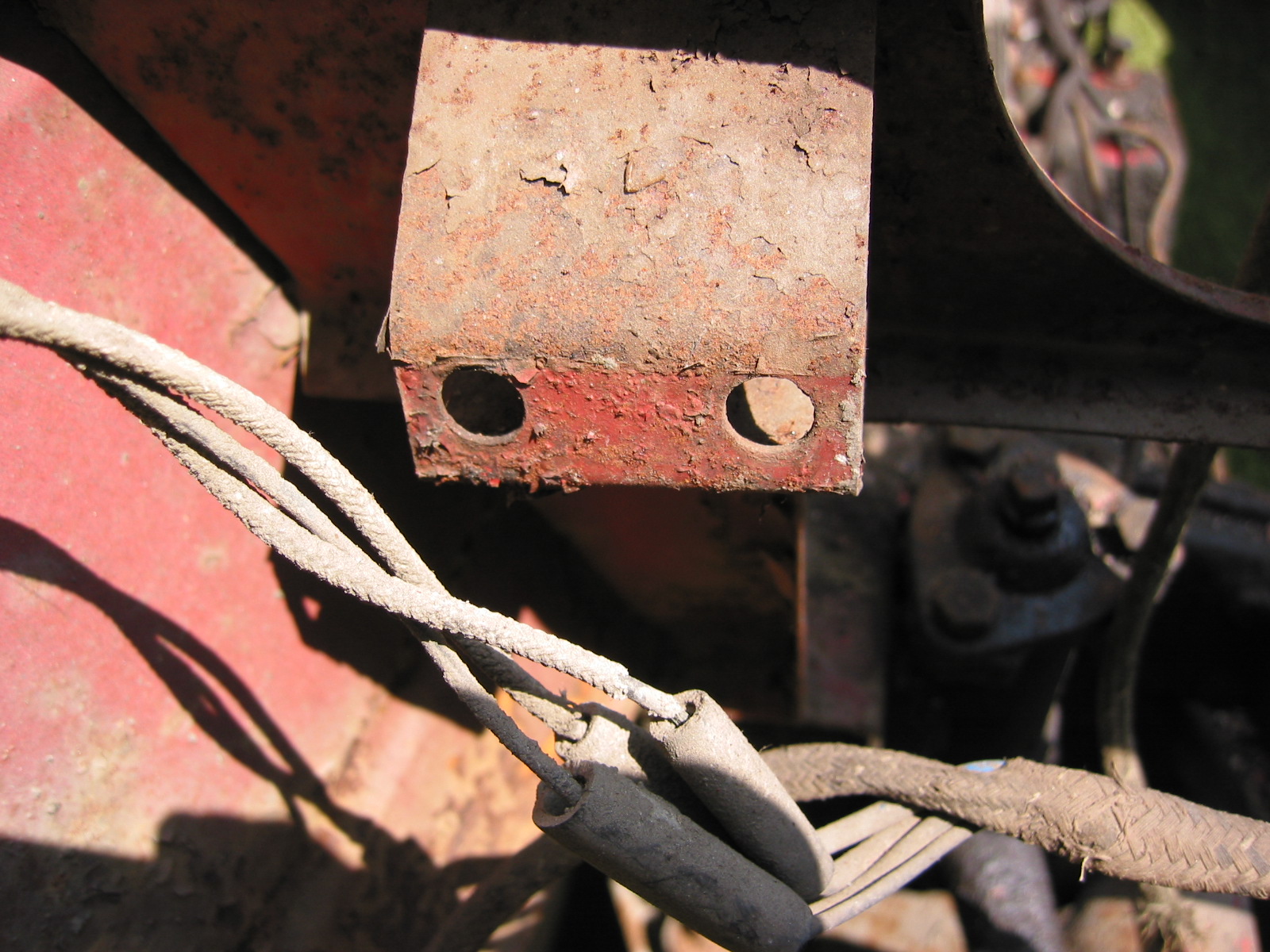
Headlamp Dip Switch
The switch didn’t look too good, but it worked fine and would clean up.

Dipper Switch
Dipper switch 4
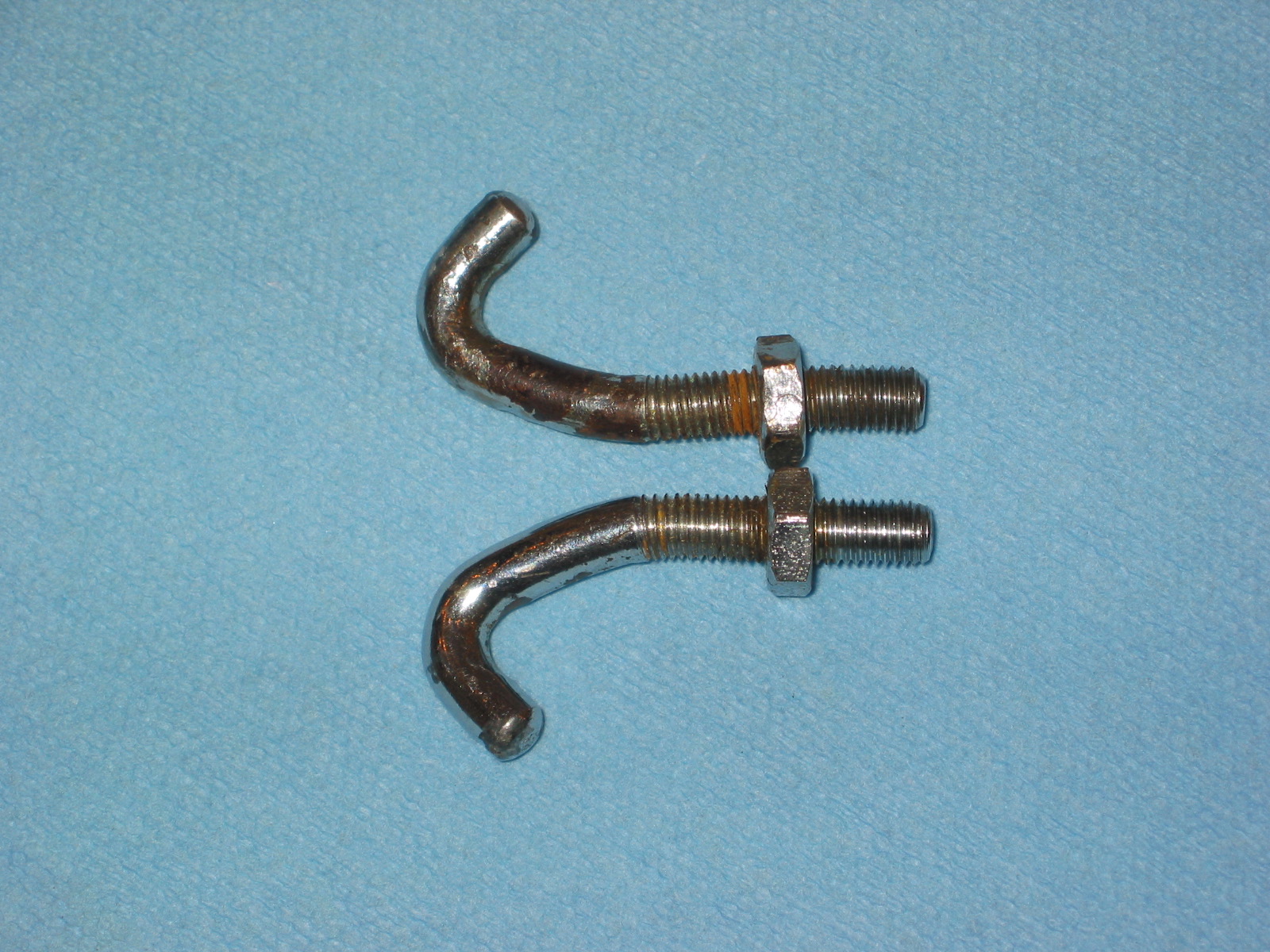
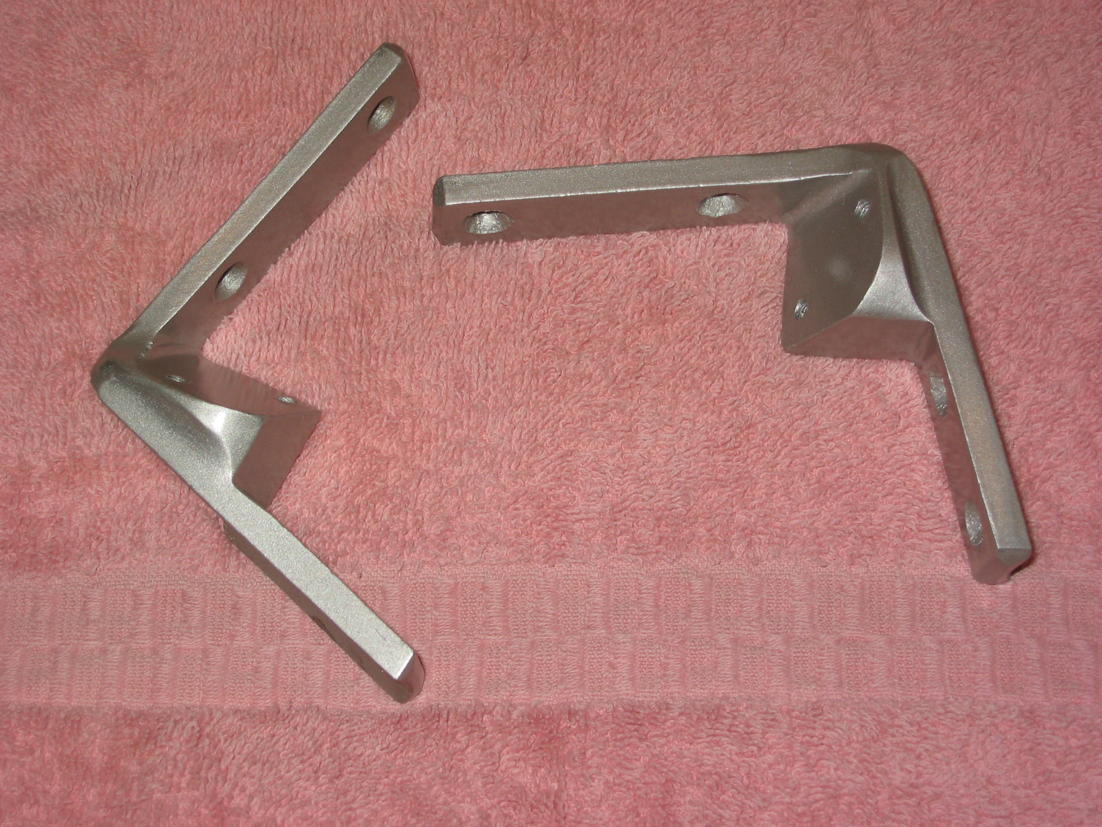
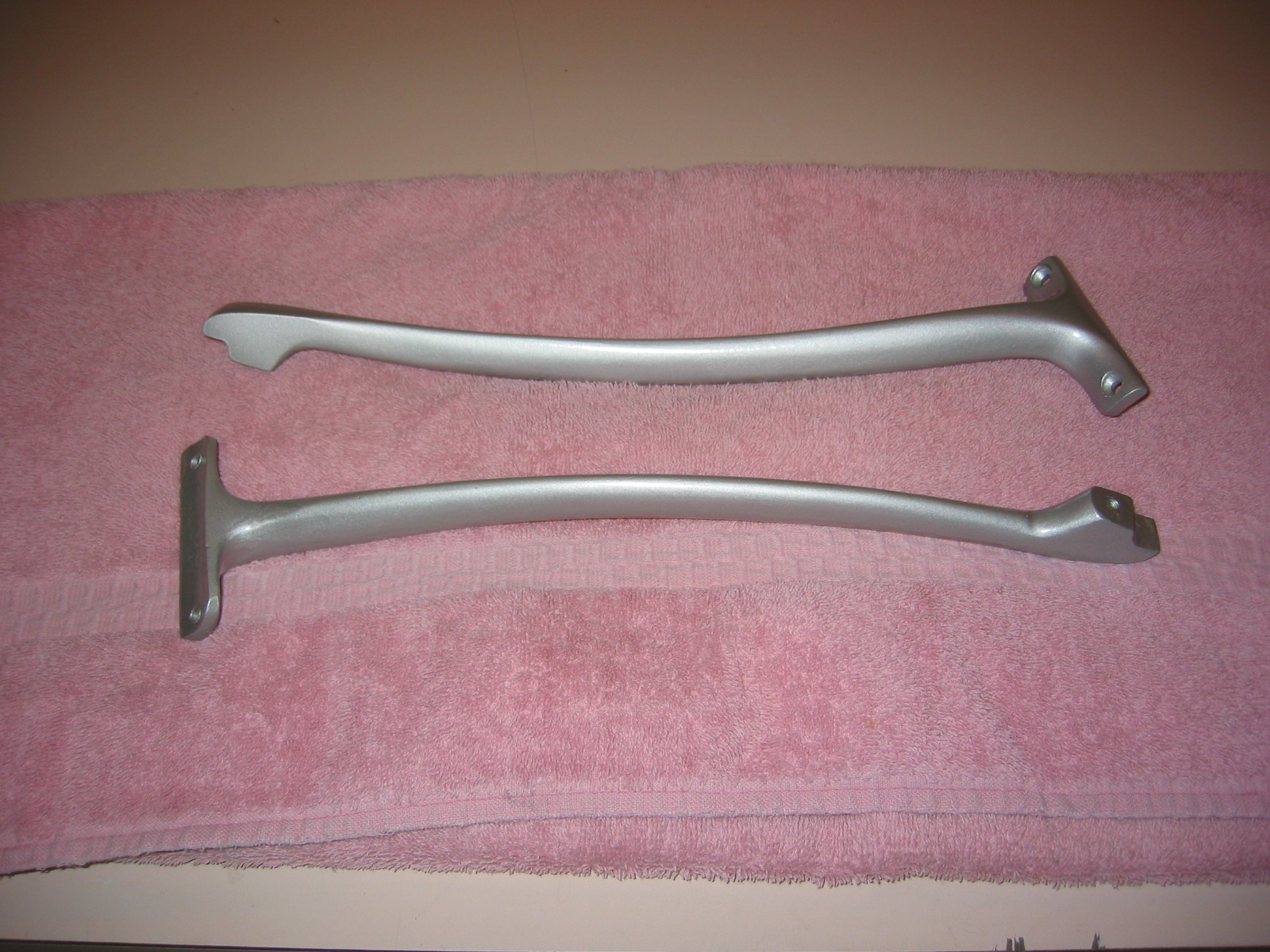
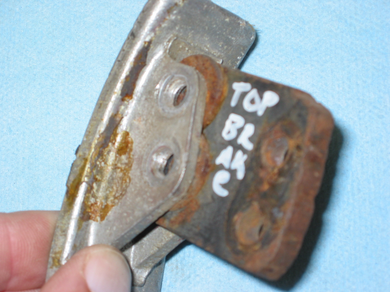
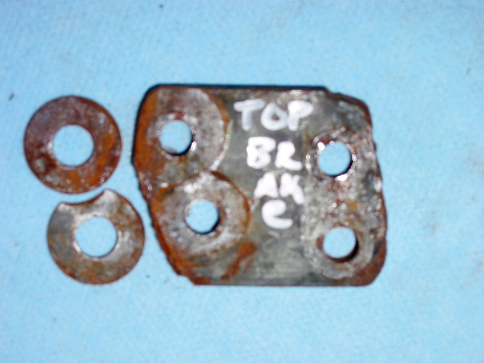
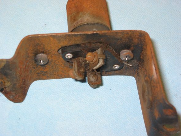
Brake and Clutch Pedals
Curiously, one of the previous owners of the car added spacers on the brake and clutch pedals to minimize reach. We won’t use the spacers.
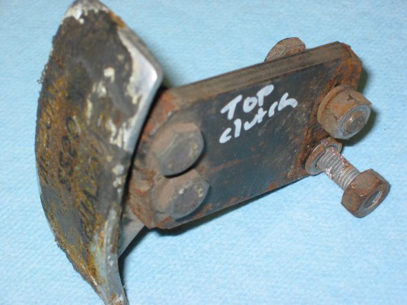
Clutch Pedal 1
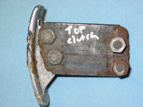
Clutch Pedal 2
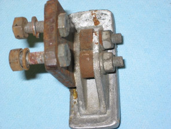
Clutch Pedal 3
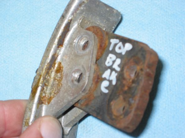
Brake Pedal 4
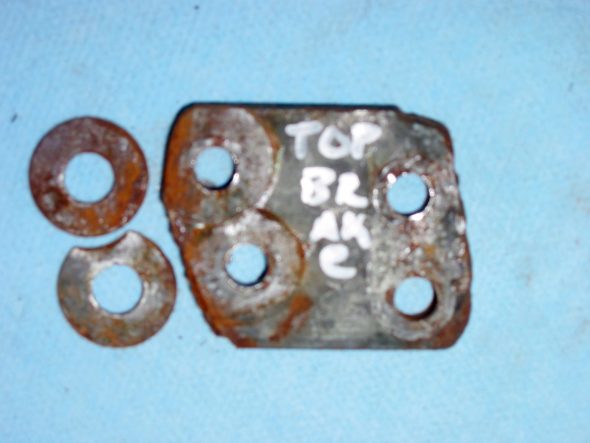
Brake Pedal 5
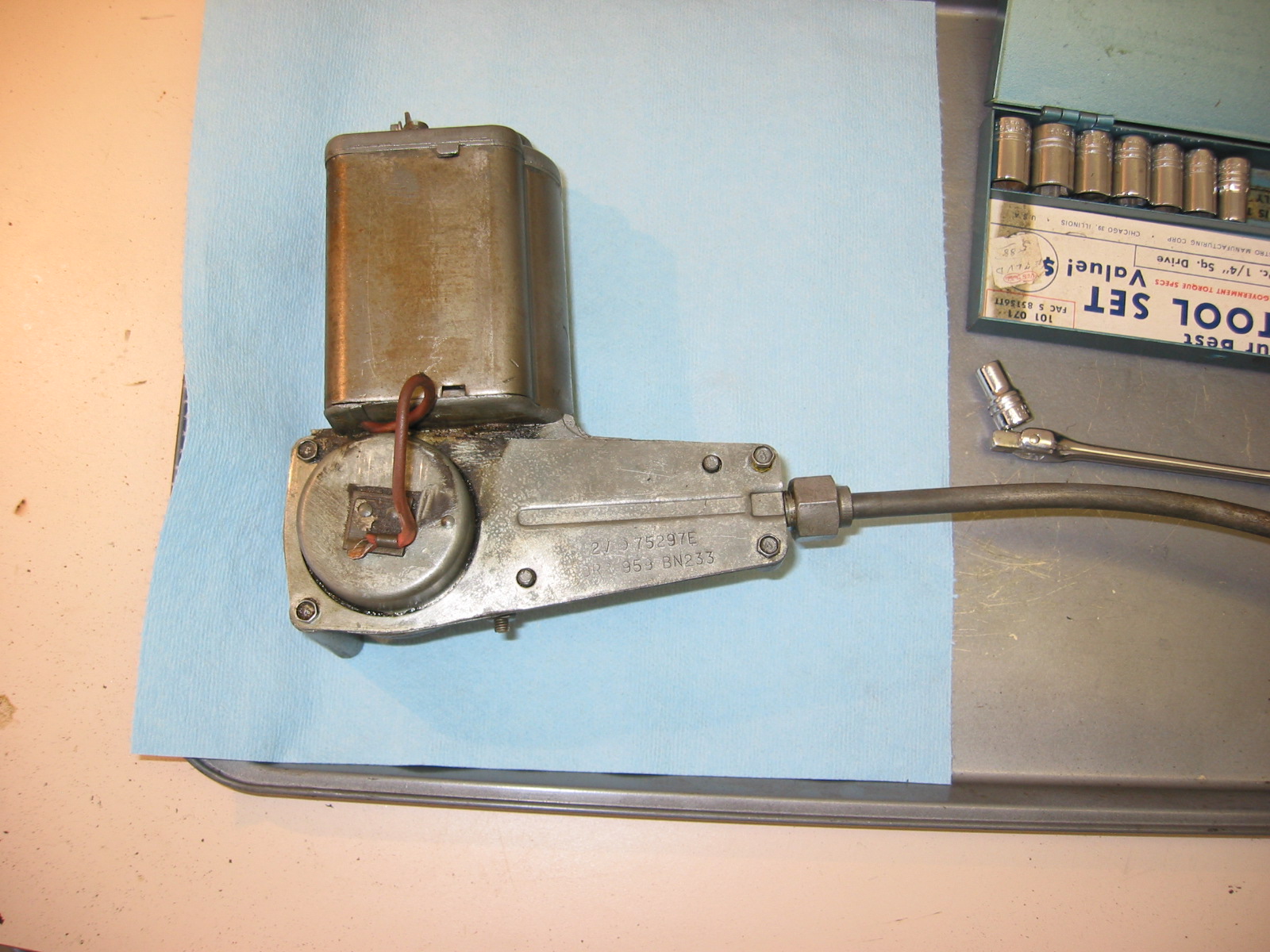
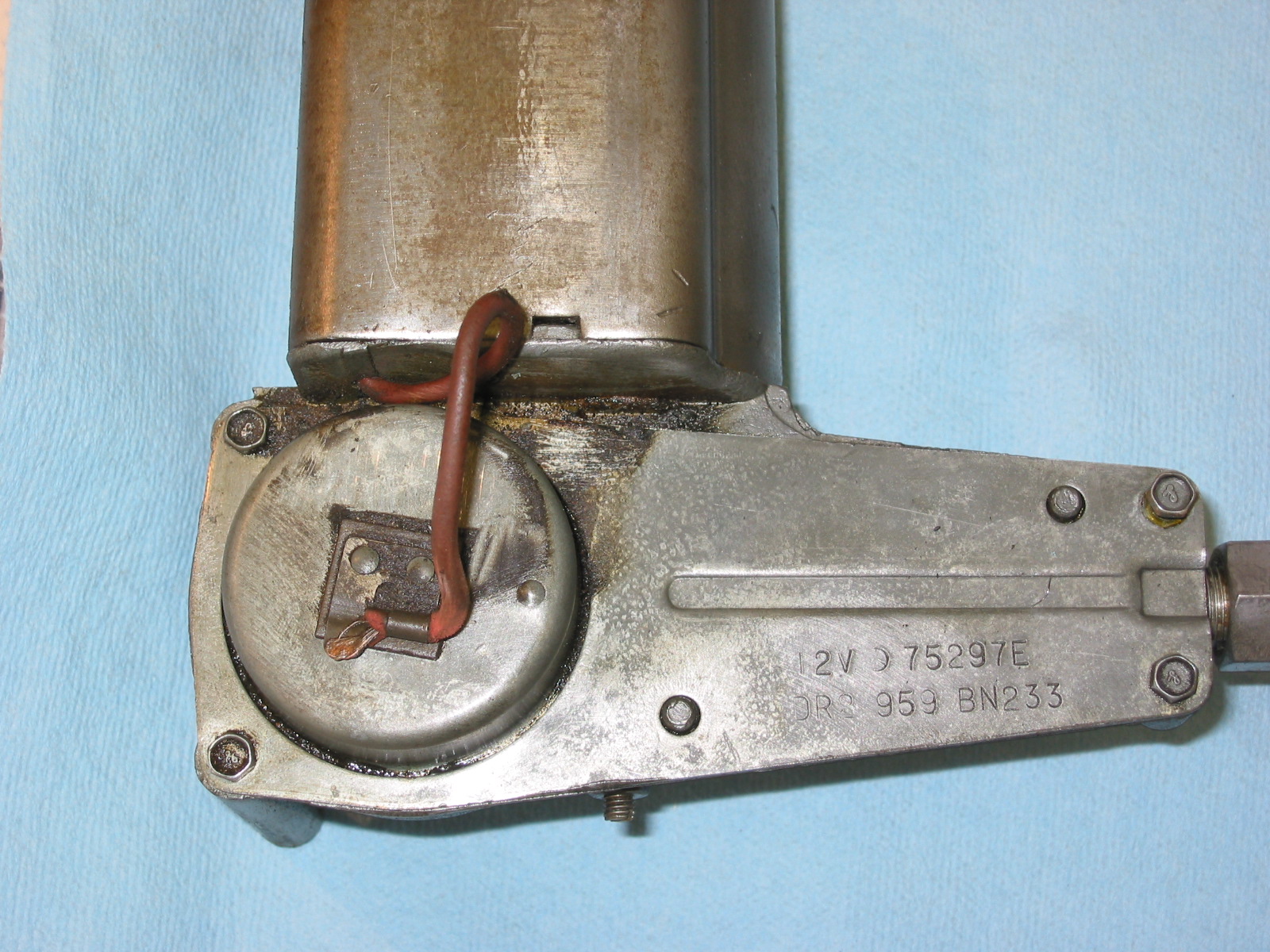
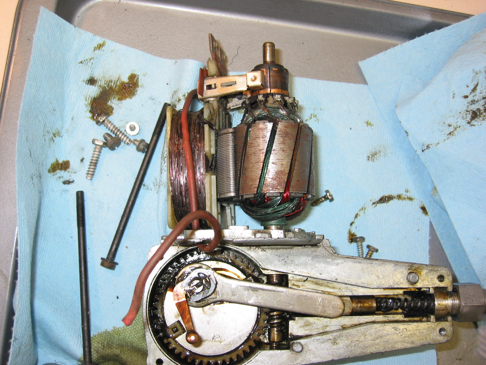
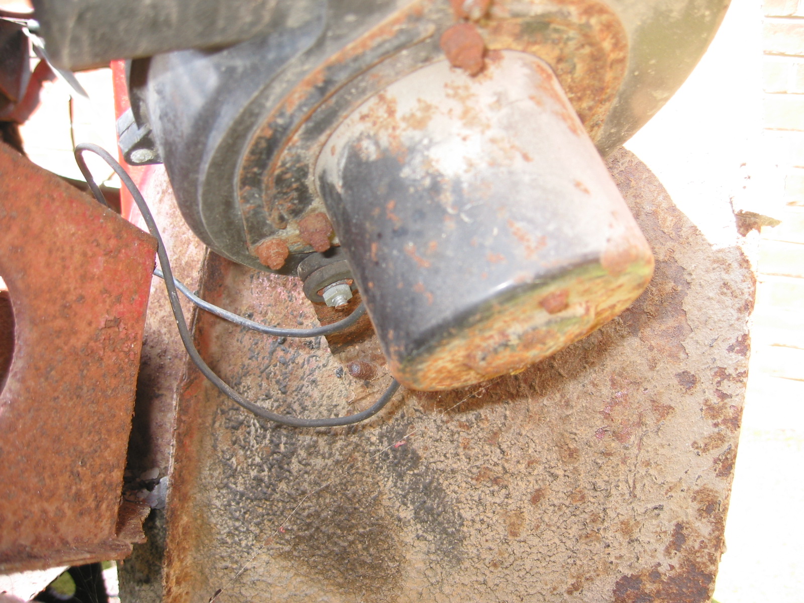
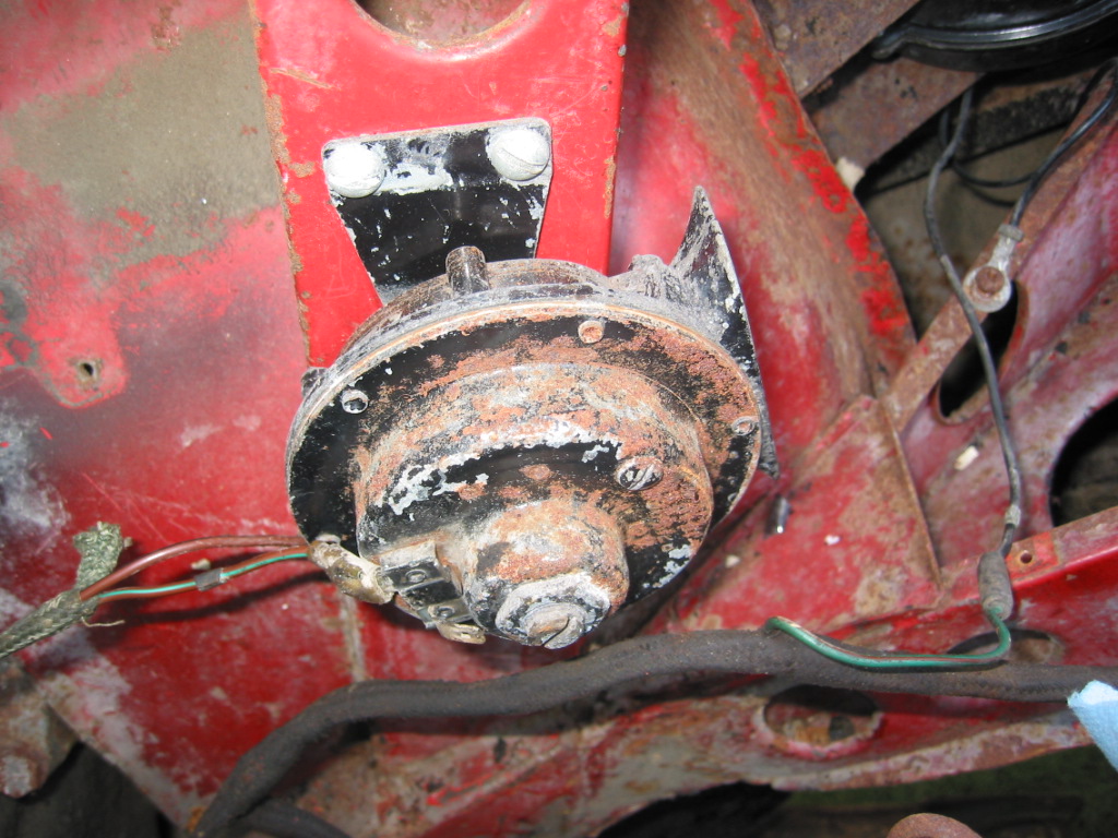
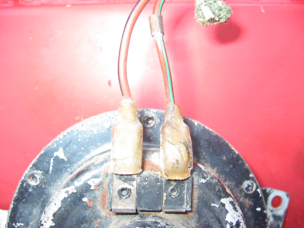
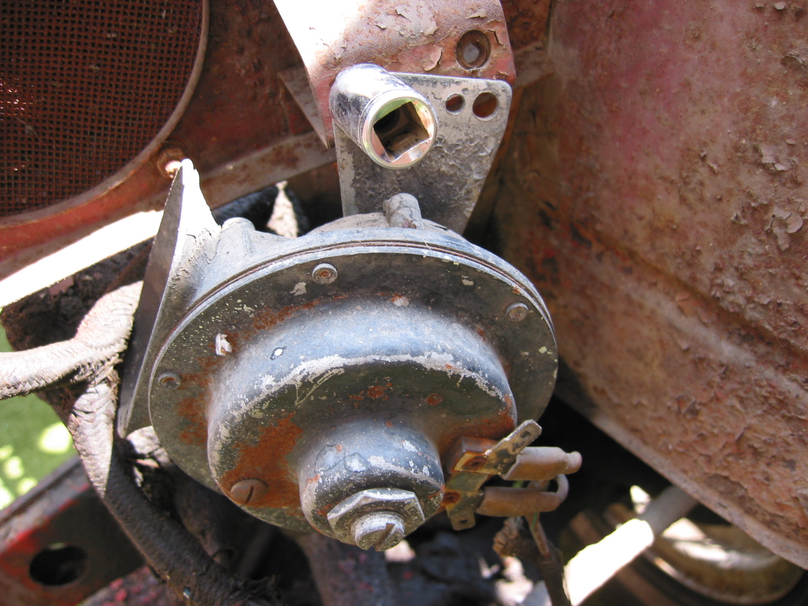
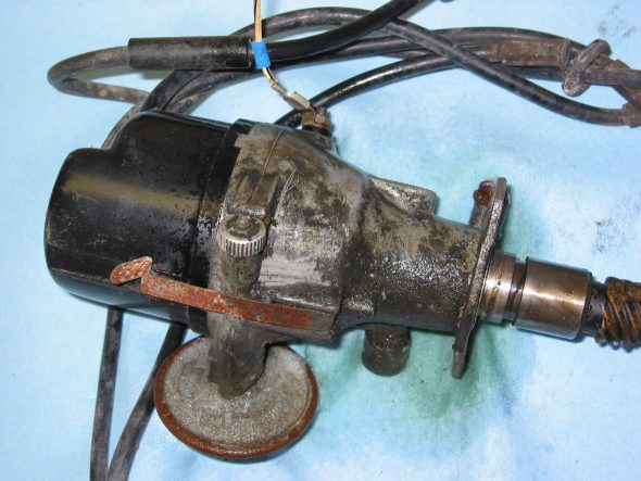
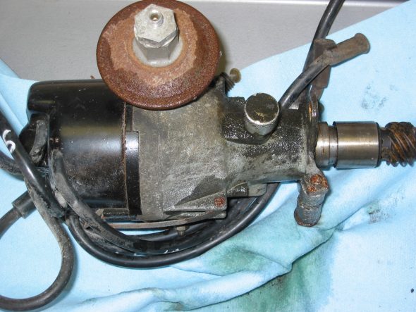
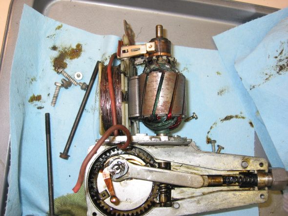
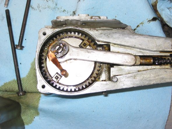
Windscreen Wiper Motor
The next item to tackle was the windscreen wiper motor. It was disassembled, cleaned, lubricated, and painted. I tested the motor and it seemed to work fine.

Wiper Motor 3

Wiper Motor 4
Wiper Motor 6
Wiper Motor 7