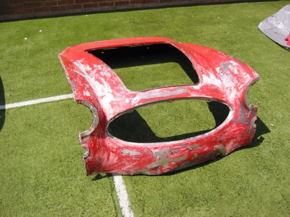
Front Shroud
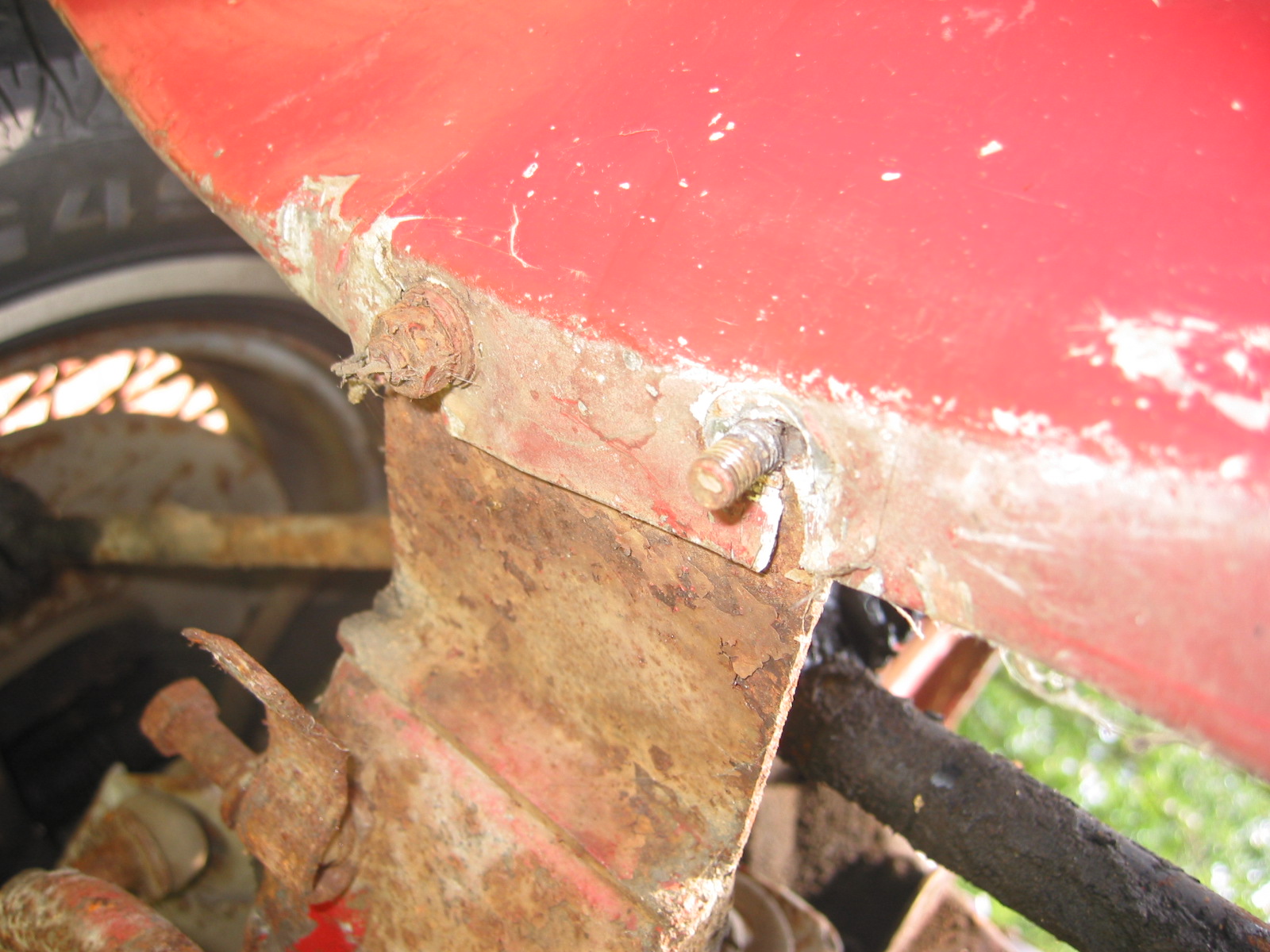
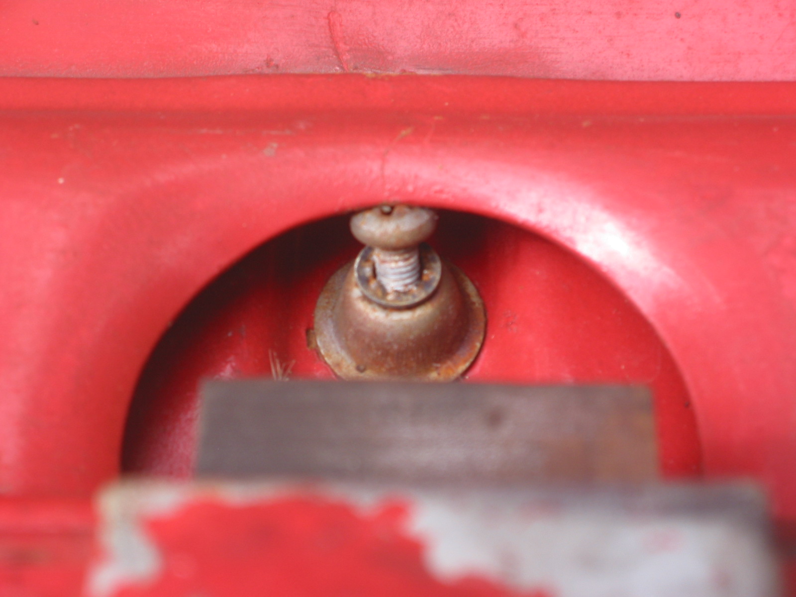
Removed five cross head drive screws at the rear of the bonnet. Three screws with nuts must be removed at the front of the shroud at the bonnet opening. Two cross head screws and nuts also attach the shroud to upright posts. A third bolt and nut holds the prop rod bracket. Five pop rivets were drilled out along the scuttle. Two additional rivets must be drilled out along each side and where the rubber seal attaches to the scuttle. Two bolts securing the shroud to each frame extension in the front must be loosened from their nuts. The shroud can then be released from the rear and pulled forward.
Prop Rod Bracket Removed

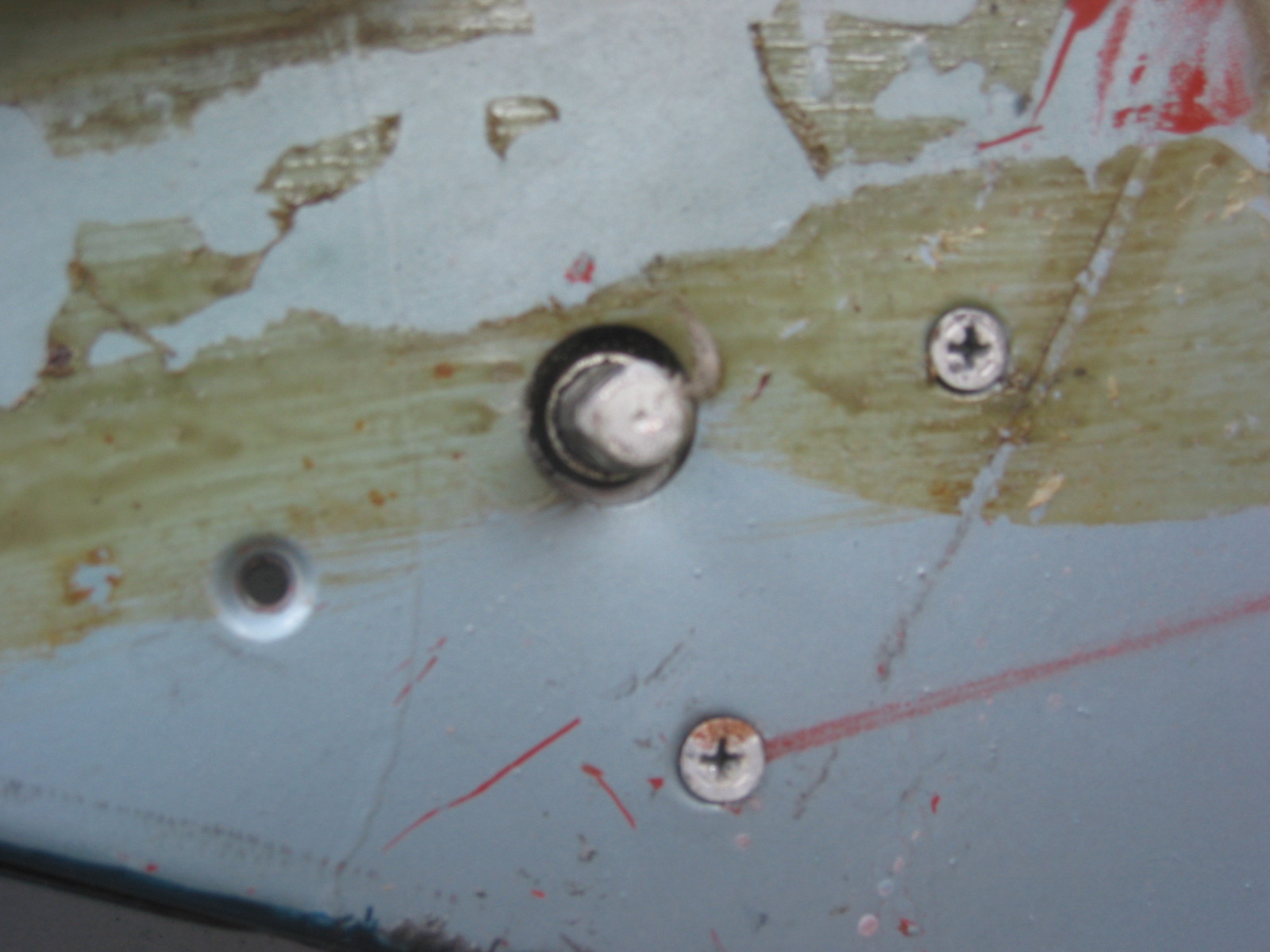
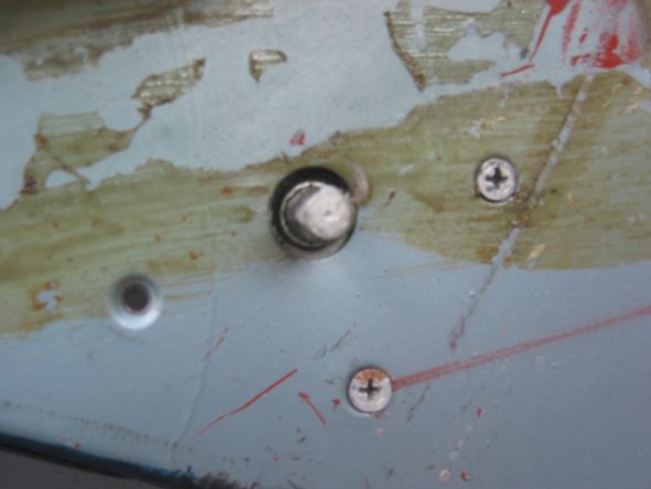
Rivet Removal

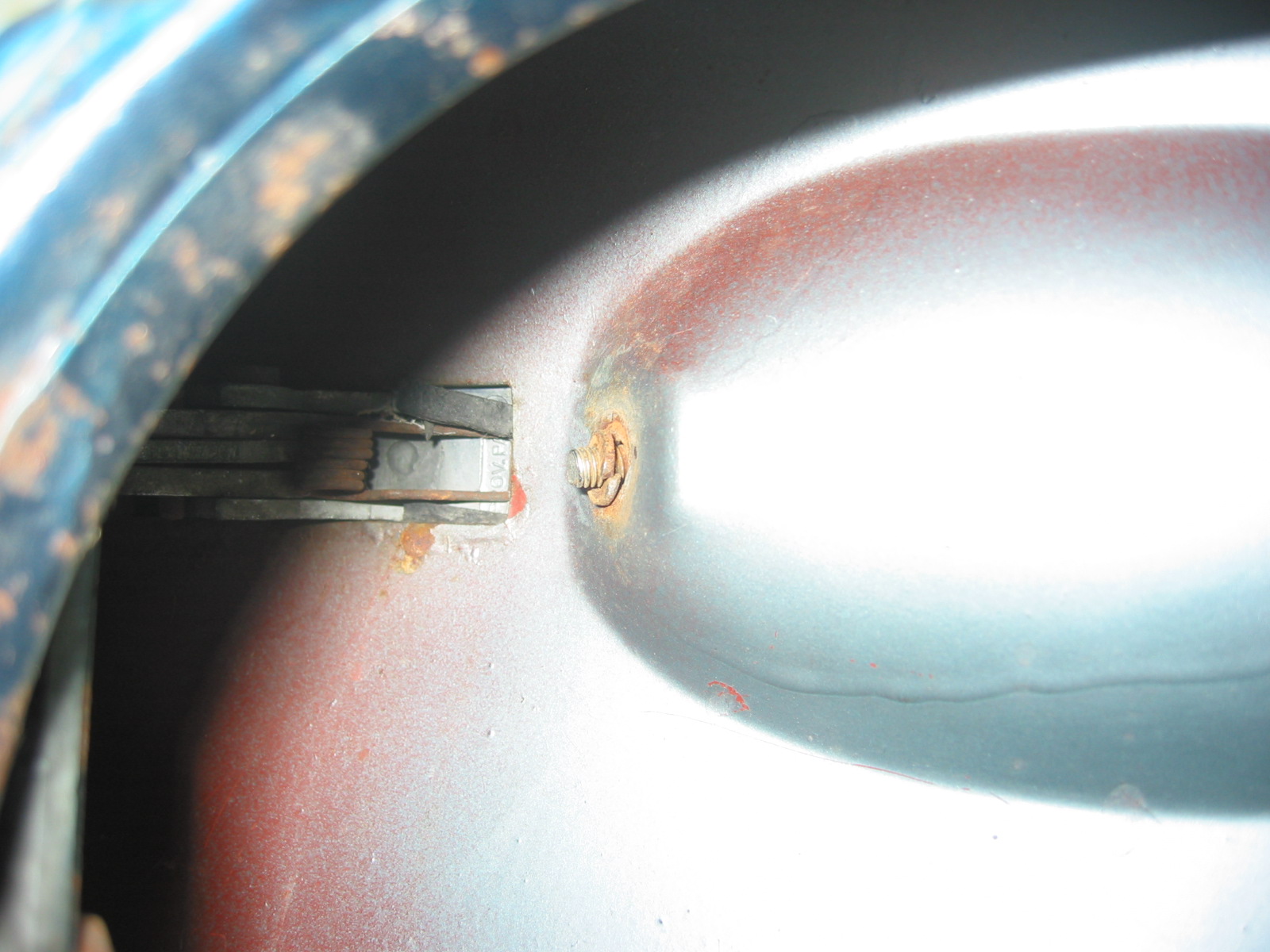
Front Shroud to Frame Mount
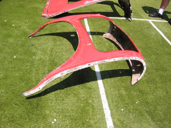
Shroud Removed 1

Shroud Removed 2
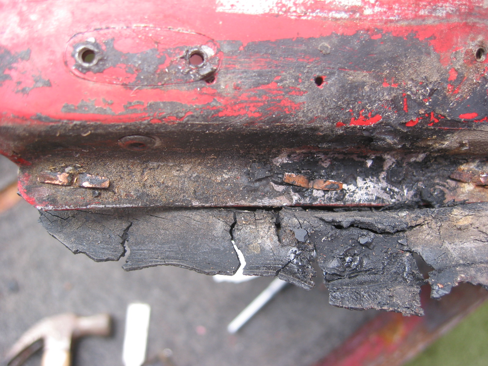
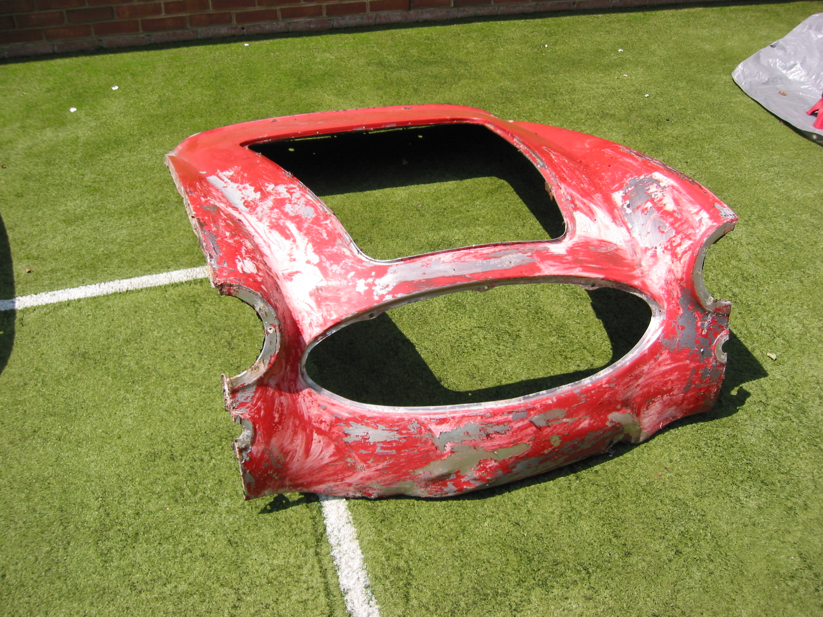
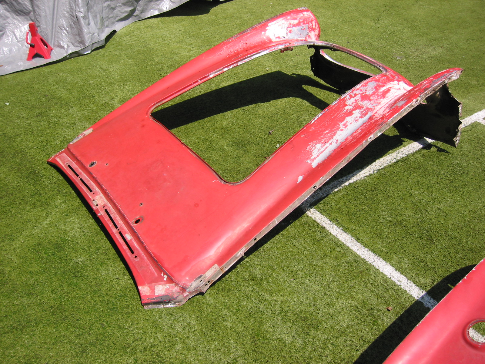
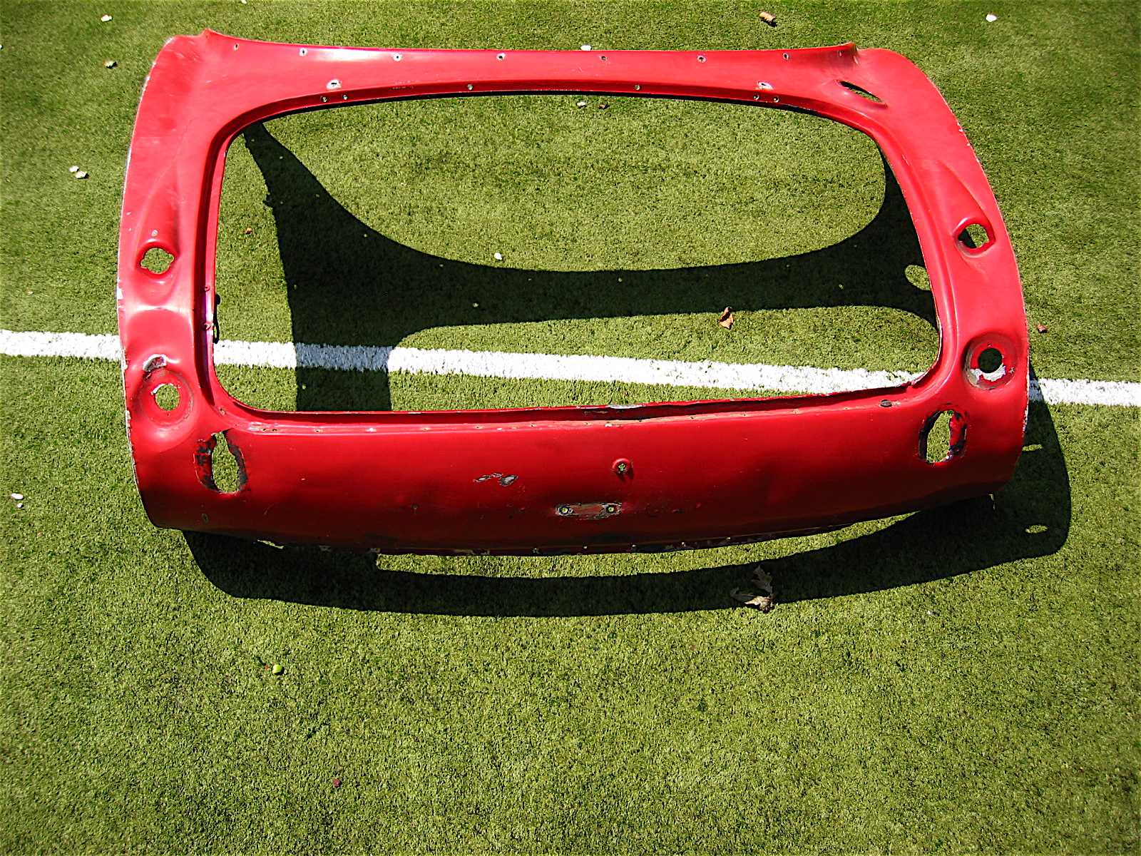
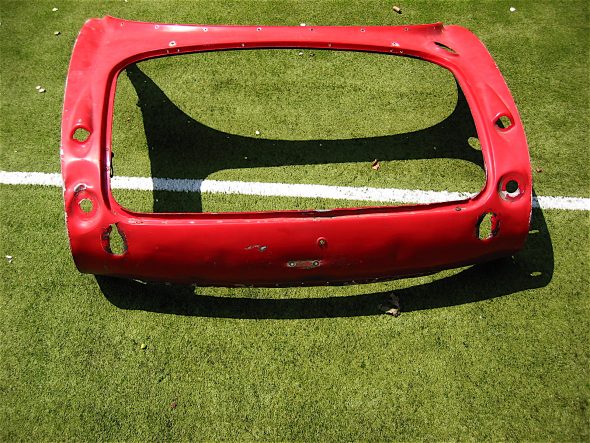
Rear Body Panel (shroud)
The rear body panel is released by first drilling out 19 rivets along the lower lip. Thirteen rivets must be drilled out that hold the body panel to the luggage compartment frame. Two or three rivets must be drilled out on the side of the rear body panel where the wing fastens to it. Four cross head screws and nuts must be removed from the top lip of the boot opening. The rear body panel can then be removed. Care must be taken to not bend the small front lip on the aluminum panel at the front points.
Rear Shroud 1
Rear Shroud 2
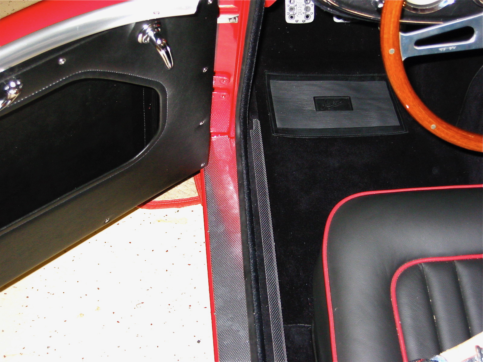
Doors
Removed three posidrive screws holding the interior door handle. Removed four posidrive screws at rear of door by handle. Removed opening mechanism. Loosen phillips head screw in door handle accessible when the door handle is pulled. 5/16” nut on the door handle screw. Loosen 5/16” nut on the screw on the back of the door handle – not easy to get to! Door handle can then be extracted from the door.
Interior Door Handle

Exterior Door Handle Fastener
Door Latch

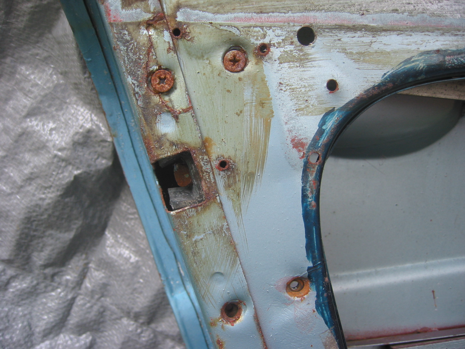
Door Fasteners
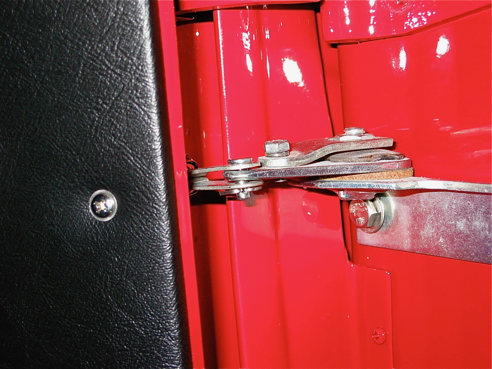
Removed side curtain bezel and retaining nut and chrome washer. Removed mid-door wood strip. One pozidrive screw on top center and two screws to the left and right on the bottom side. Removed the door strap (catch).
Door Catch Mechanism
Interior Door Trim Panel Wood
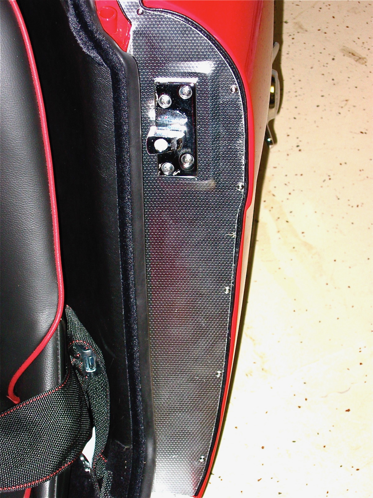
Door Opener Mechanism Orientation
Remove door hinges. Four bolts into a securing plate for each hinge. Drilled small indentation into the top bracket to recognize it. On reassembly of doors mount outside door handle first. Then install mechanism so that the action arm is in the proper place.

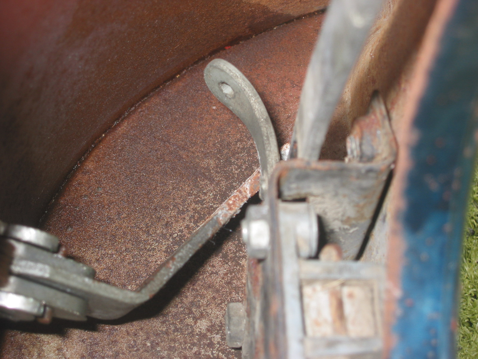
Door Catch at Door

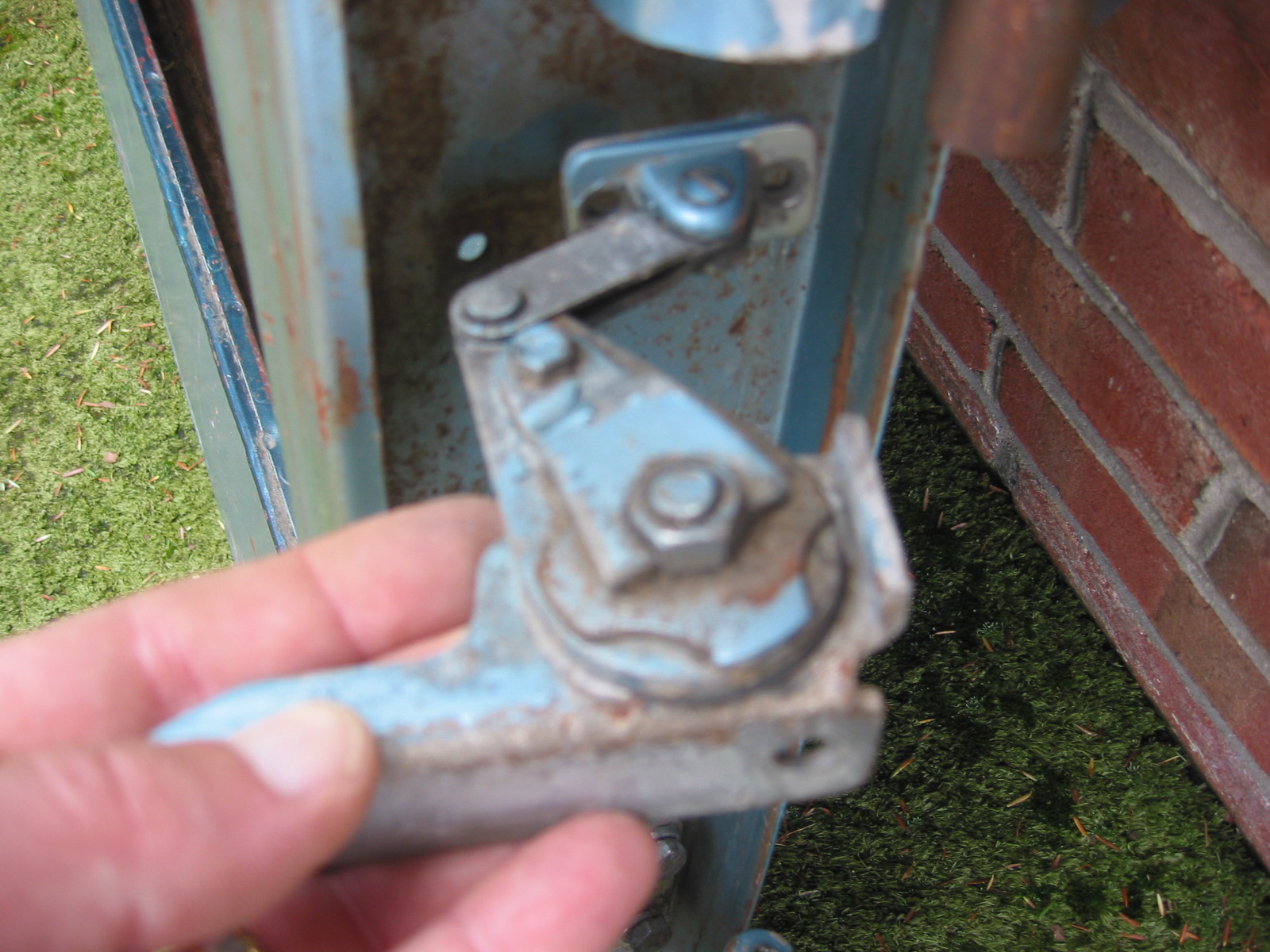
Door Hinges
Aluminum Door Hinge
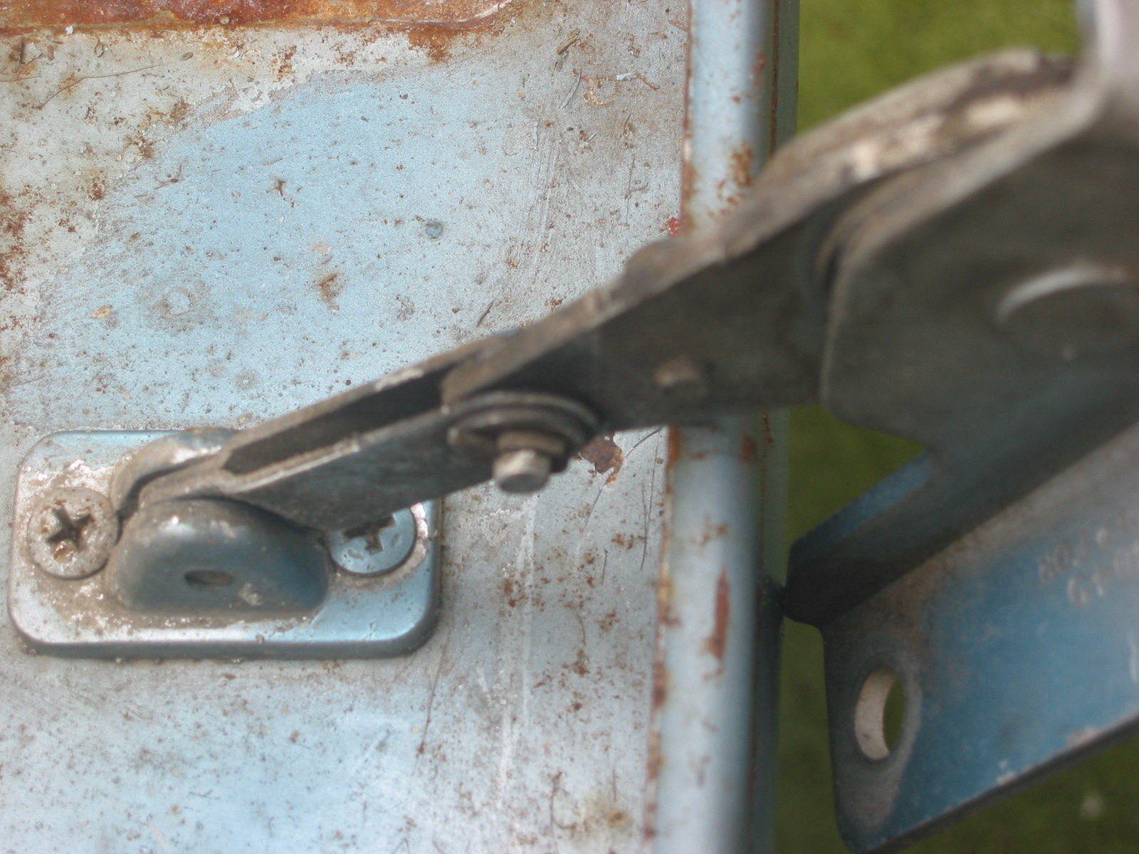
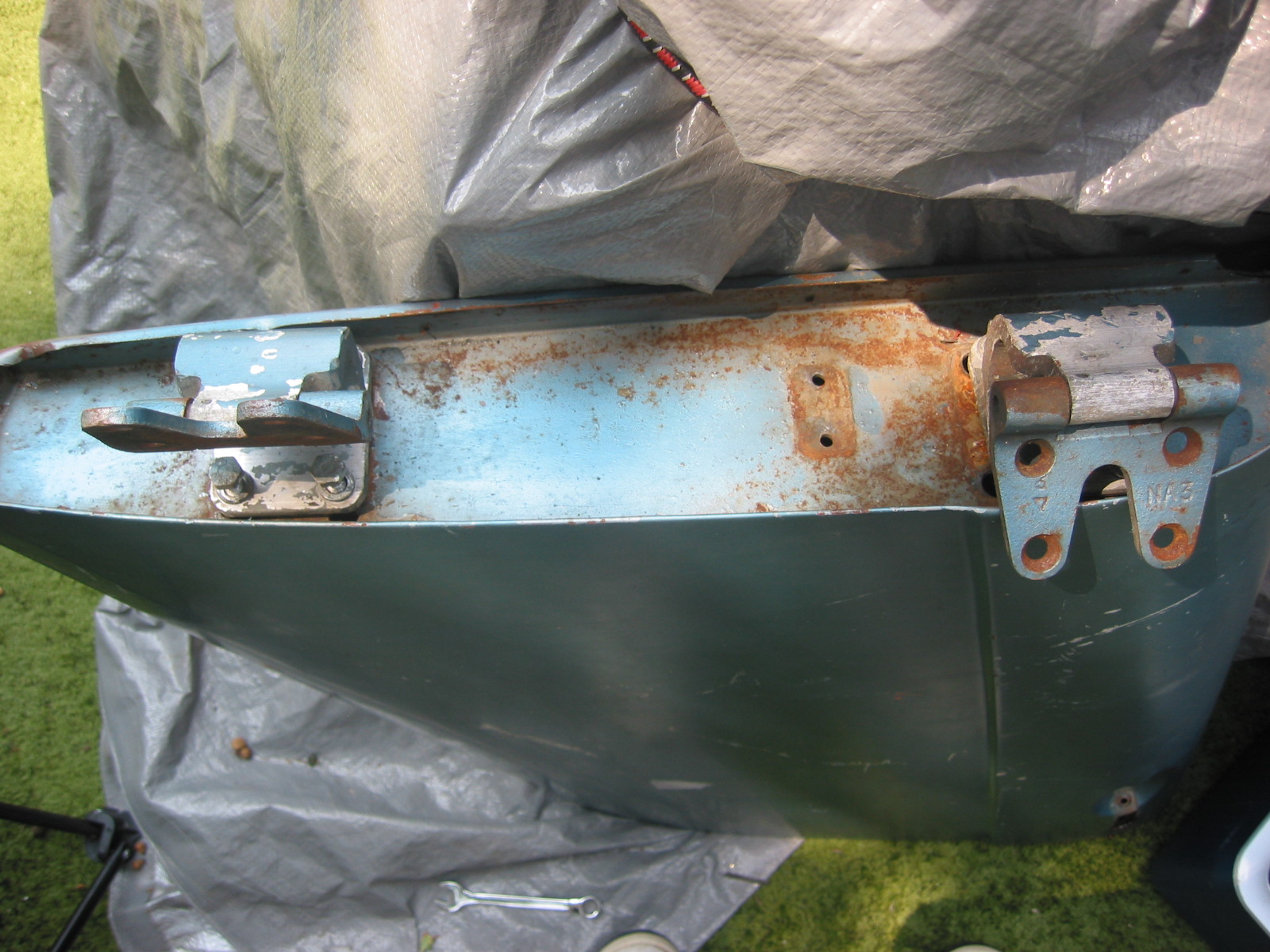
Boot Lid
Removed two screws and cup washers securing the handle/lock. Remove four bolts/nuts holding the lock/catch mechanism. Remove one screw holding the locking mechanism post. Lock surface was painted as were the screw tops so it was installed when the car was painted. The chrome lock and handle were installed after the car was painted because the locking post screw was not painted.
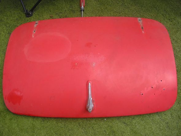
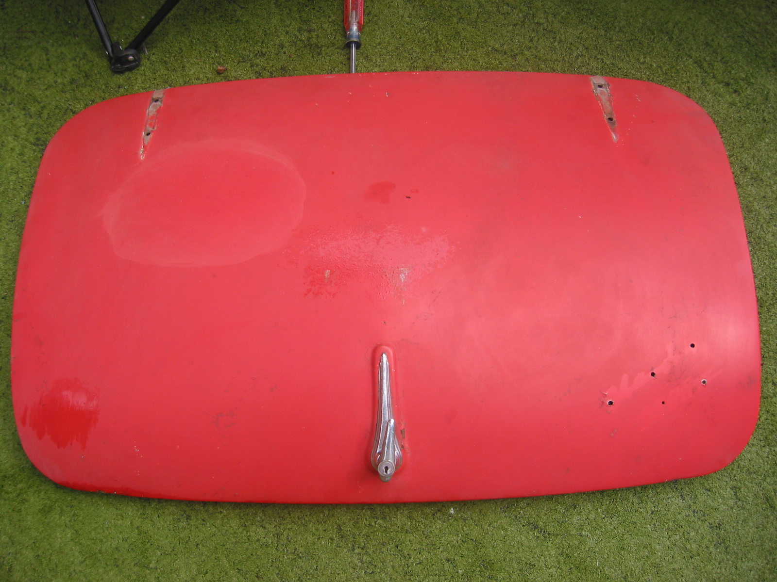
Exterior Boot Lid

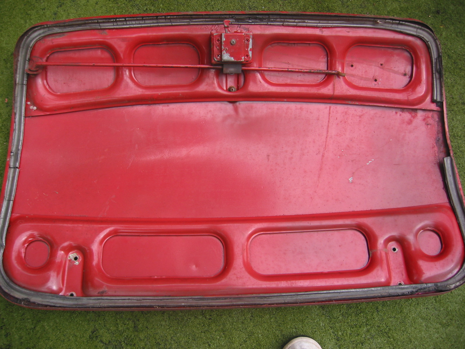
Interior Boot Lid

Boot Lock Handle
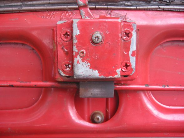
Boot Lock
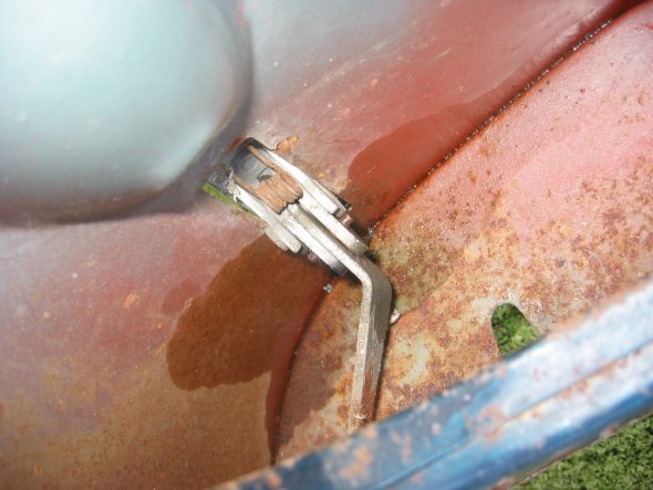
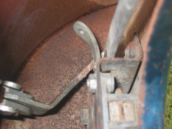
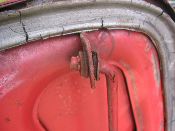
Removed the large cotter pin holding the rubber boot lid support rod. The rubber could then be removed as well. The head of he pin was located on the rod locator bracket side. A small cotter pin was removed from the support rod at the home bracket. The rubber grommet was then removed and the rod was detached.
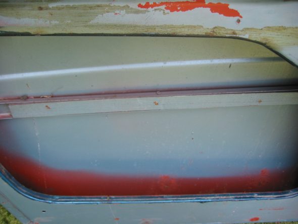
Removed rubber gasket sealing boot lid.
Boot Rubber Seal

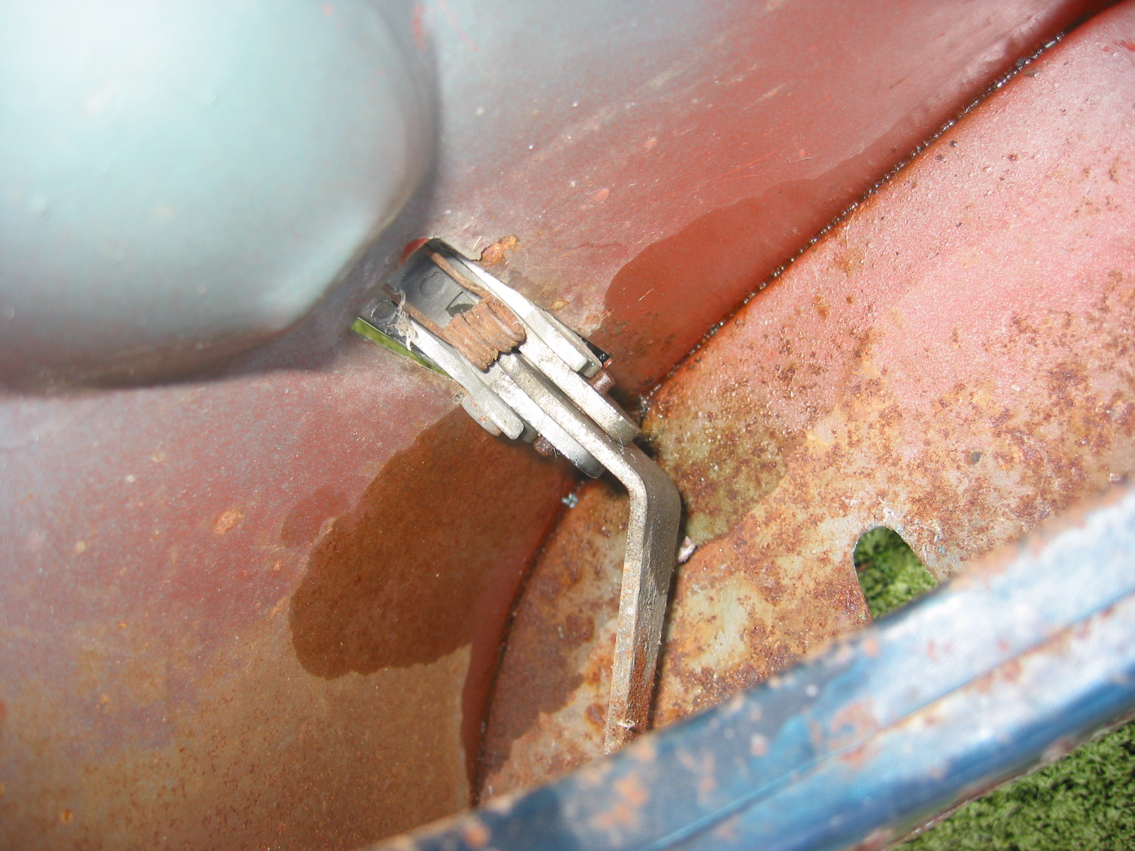
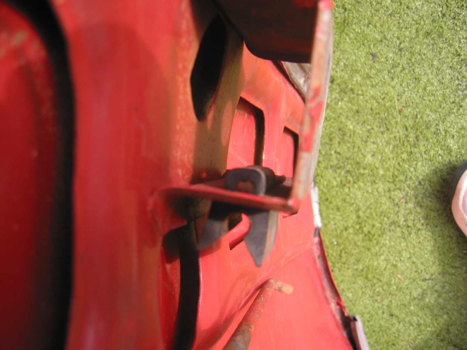
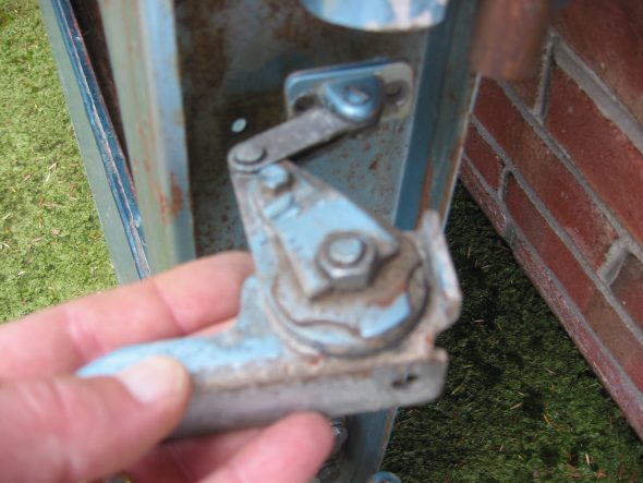
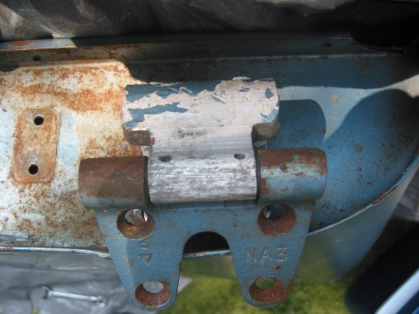
Boot Prop Rod Clasp
Heater Blower Assembly
Removed four nuts on posts through rubber grommets. Black ground wire connects to the angle pillar. Power is through a green wire with a brown stripe that plugs into a rubber junction.
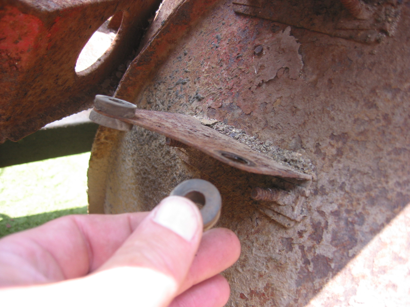
Removed the two heater blower mounting brackets. Two bolts each through wheel well arch. Large washers used on the tire side of the arch.
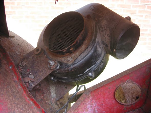
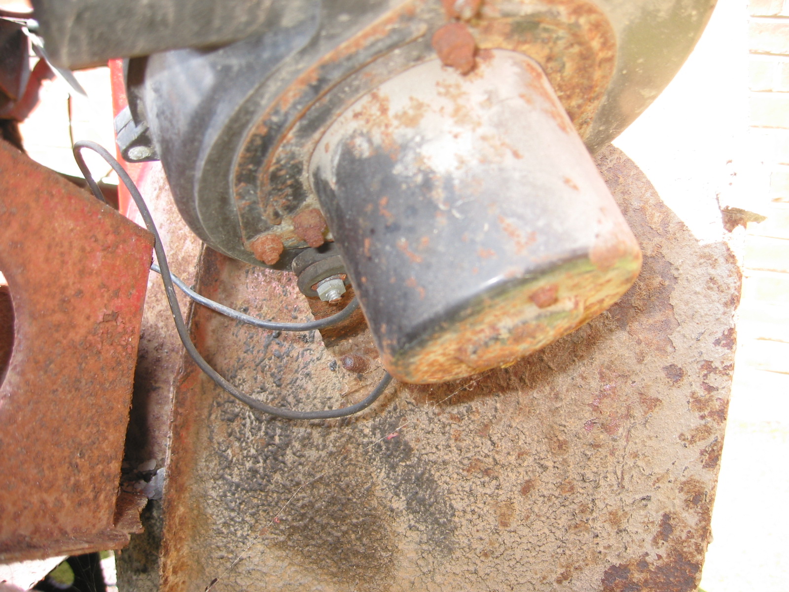
Smith’s Heater Blower
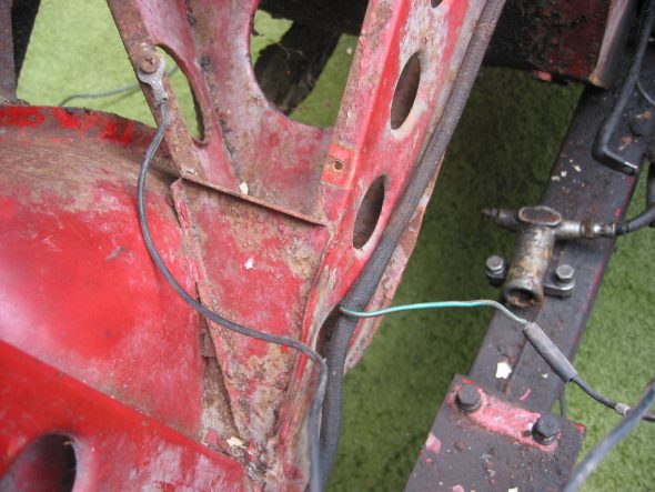
Blower Mounting Location on Frame Upright

Blower Mounting Rubber Grommets

Blower Motor Wiring Connections
July 28, 2002
Under Bonnet Components
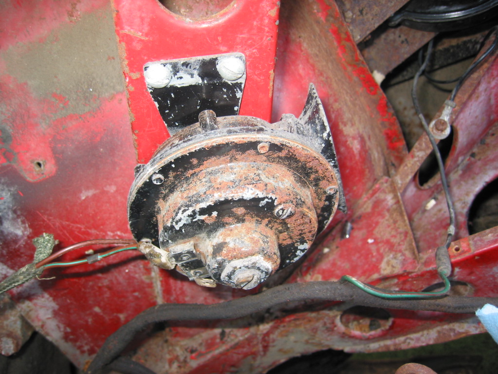
Horns – Located on the left and right of center under the front shroud. Each horn is secured with two bolts fastened into small steel threaded plates. I don’t believe my horns or brackets to be correct as one was mounted on the vertical shroud support like later cars.
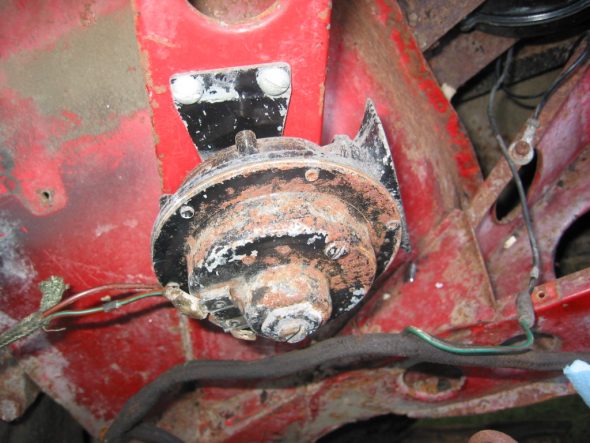
Horn on Shroud Upright

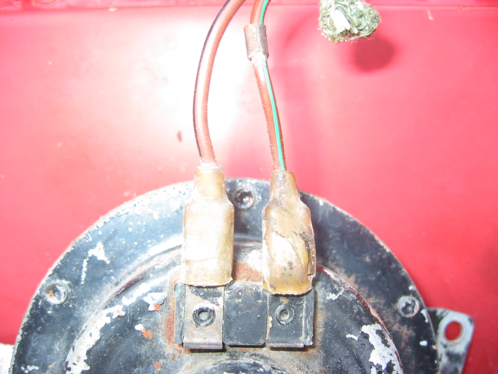
Horn Wiring Connections
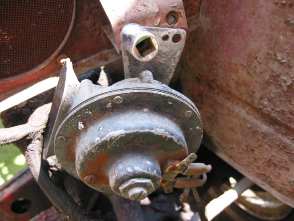
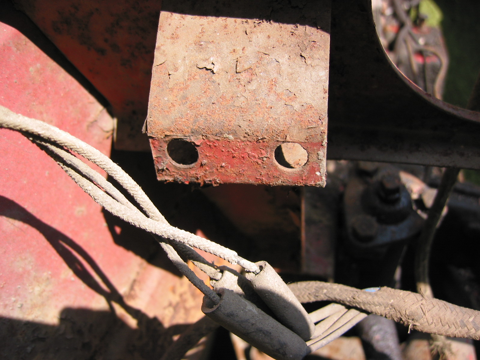
Proper Horn Location Under Front of Shroud

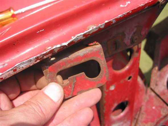
Horn Mounting Bracket