Steering Installation

The steering installation story in the Bugeye has been characterized by fits and starts. This often happens in restorations because systems frequently interfere with the installation of other systems. The new steering rack was first discussed in Bugeye Restoration Video Episode Thirty-five: https://vimeo.com/810655660/46123c8339?share=copy The steering rack is a new one purchased from AH Spares. Information related to the steering rack begins at the 5:00 minute point of the video.

Bugeye Restoration Video Episode Eighty-seven shows the installation of the steering components of the car.

Bugeye Steering Components

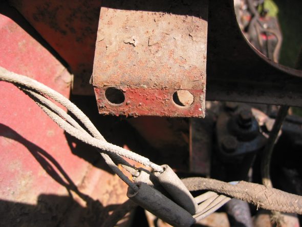
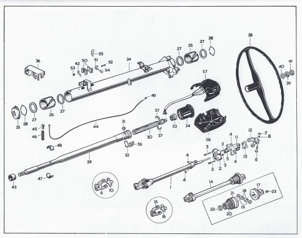
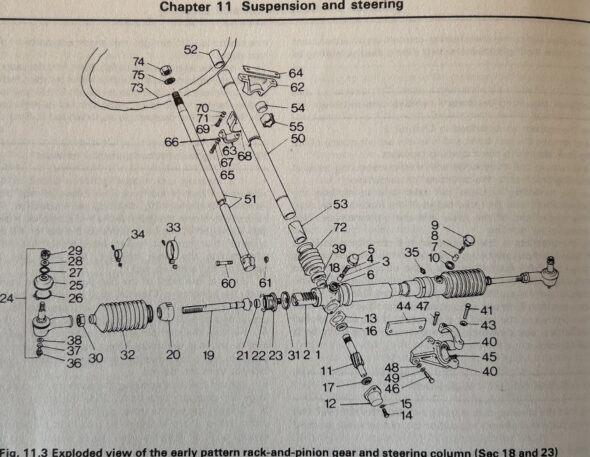
We almost missed the shim that fits between the chassis crossmember and the passenger side of the steering rack bracket, part number 44 in the diagram above. This shim aligns the steering column through the dash at the correct angle. We sourced a new one from AH Spares.

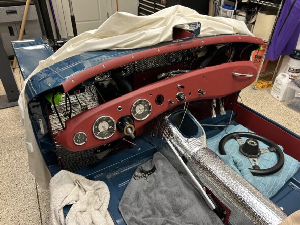
The trickiest part of installing the steering system was the coordination required with the installation of the dash. We installed the column through the firewall and let it hang loose. We then positioned it through the hole in the dash and gradually moved both the column and dash upward and into position on the car. Only then did we begin to connect the various components of the steering system. The horn cone was installed with its three mounting screws, but with plenty of room to move around as the column shifted position. All parts were loosely fitted to ensure that we didn’t have any binding of the parts as they were assembled.

Dash with zip ties to the body and column in position

In our final installation we had already centered the steering rack and had also threaded the new tie rod ends to the proper location to hopefully result in a rough alignment of the wheels permitting us to roll the car around in the garage. We will find out later if we were successful! Of course, we will align the steering professionally when all is done.

The following points are covered in Bugeye Restoration Video Episode Eighty-seven:

https://vimeo.com/1010637487/a43c135b98?share=copy

0:00 – Steering column bracket, grommet, and bushings

1:56 – Steering column firewall corrugated grommet

2:18 – Stering rack shims

2:49 – Steering column to steering rack locking bolt

3:00 – Steering rack to chassis brackets installed

3:22 – Steering rack to chassis shim

4:12 – Steering rack bracket bolt torque values

4:22 – Coordinating the dash and steering column installation

4:40 – Final steering components installation sequence

6:19 – Horn cone positioned and secured

7:22 – Testing the steering column connection to the rack

8:20 – Connecting the tie rod ends

9:00 – Steering wheel installed

9:30 – Horn test


nn

Chapter 34 Week One 12/18/2016

Even with all the restoration books I have read, and with all the e-mail exchanges, no one prepared me for the fact that I would develop a phobia about touching the car now that it has finally arrived! I am afraid to touch the thing for fear of scratching it!

My plan is to begin with the brake and fuel lines, then move to some of the interior dynamat installation followed by the electrical wiring harness. Along the way I am sure there will be diversions to other bits and pieces. I will try to be disciplined about this process and avoid the temptation to just start attaching pieces to show progress. Although I am confidant that I will succumb to that diversion from time to time!

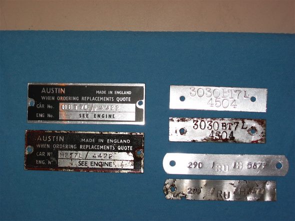
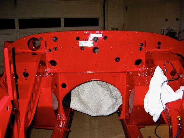
It seemed entirely appropriate that the very first components to be installed should be the two production identification number plates on the firewall. These were produced by Clarke Spares and Restorations. The original ID plates had to be shared with them before they would produce new plates.

Number plates

I.D. Number Plates

Then I began by chasing the threads on all fixed nuts throughout the car to eliminate primer and paint before securing fasteners. Just that little job took about 2 1/2 hours.

chasing threads

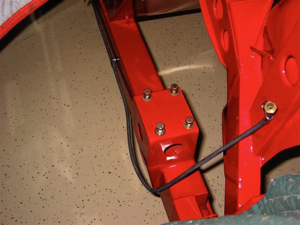
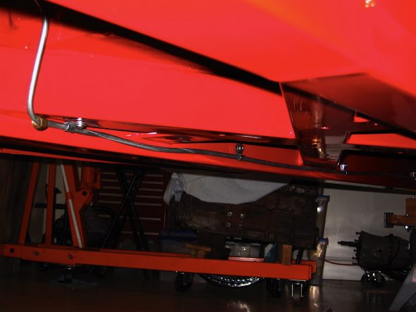
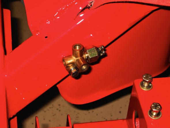
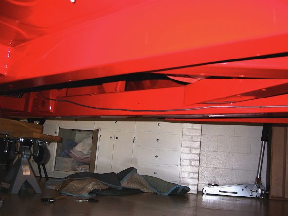
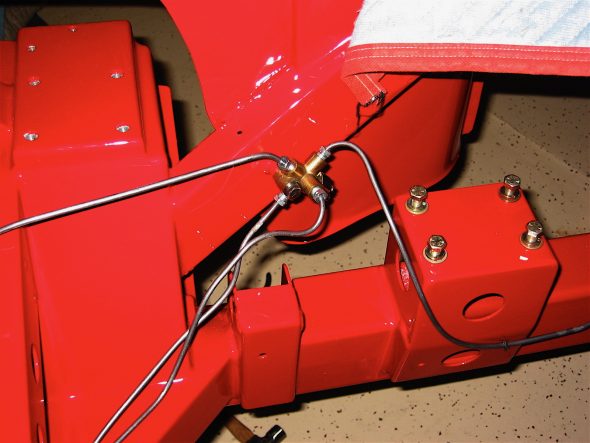
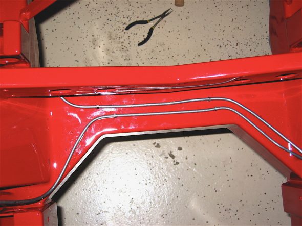
Then it was on to the hydraulic lines. Fuel line first, followed by the brake junction and the brake lines and the line to the clutch master cylinder. Having drilled all the mounting holes after the frame arrived from Martin, this job moved along very quickly.

Fuel line 1

Fuel line 2

brake pipe union

Brake line 2

Brake lines at union

Front brake lines

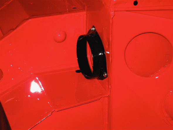
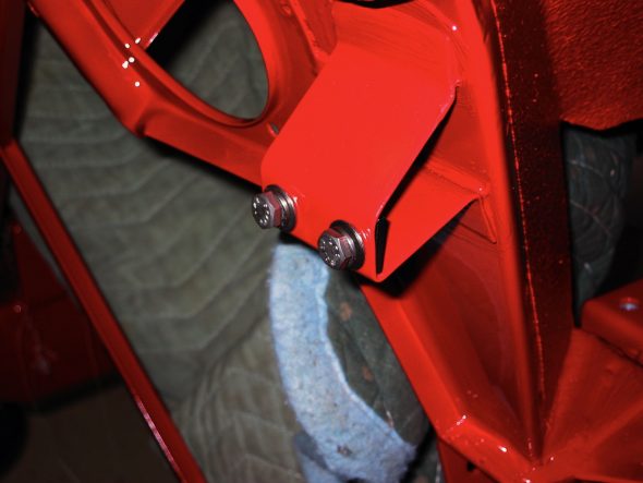
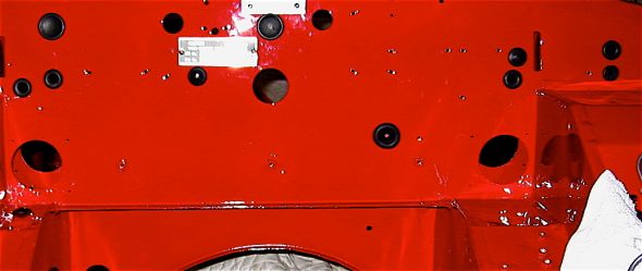
My first two diversions were the horn brackets and the air intake flange. These were installed next. Then came the firewall rubber grommets, and again this job was made easier because I had pre-fit and numbered these at an earlier stage.

air intake flange

Horn bracket

rubber firewall grommets

I moved on to beginning the process of controlling interior cabin heat and improving sound insulation. Fred Wescoe produced an excellent piece on interior insulation that proved very helpful. Making your Healey Cool Fred Wesco .

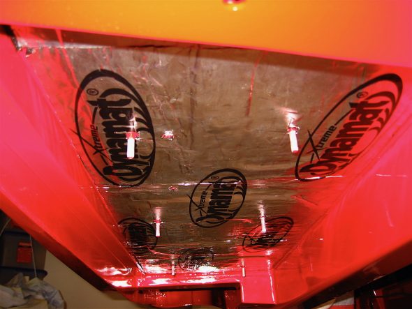
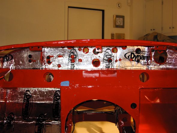
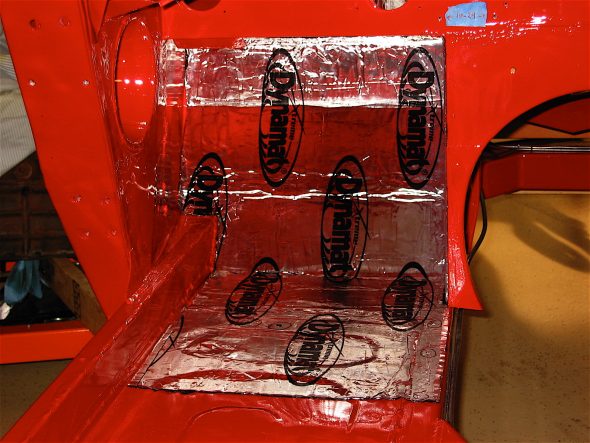
Our cars originally used a tar paper product and jute under the carpet for this purpose, but contemporary products provide much improved insulating qualities. On the advice of others I decided to use a product called Dynamat Exteme that has a very sticky adhesive rubber type surface on the underside and a foil surface on the top. After making patterns from butcher paper the individual pieces were easy enough to cut just using scissors. They were then carefully applied and rolled on with a wallpaper seam roller. Aluminum tape was used to seal all of the seams. All of this produces a nice looking appearance that will hopefully keep the heat down in the cockpit.

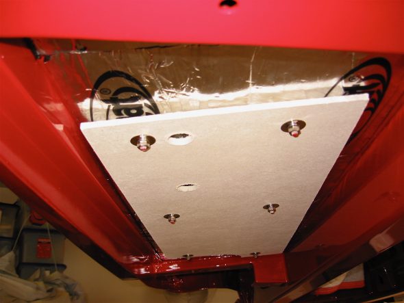
The installation of the first piece of the dynamat extreme went under the car, below the driver’s seat and above the muffler insulation panel. Then the stock insulation panel was secured using the six studs through the floor.

Dynamat Extreme 1

Muffler Insulation Panel

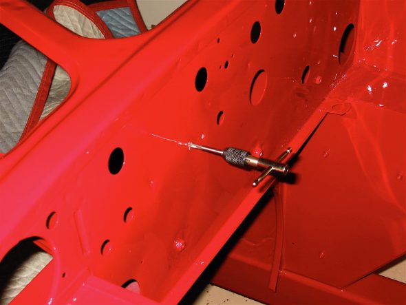
I then moved on to the interior of the firewall and to the driver’s side footwell. I used an awl to find the holes in the interior floor and to make holes through the dynamat material.

Dynamat Extreme 2

Dynamat Extreme 3

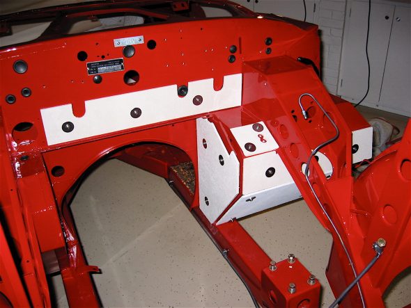
Next I fastened the insulation panels in the engine compartment.

Engine Insualtion panels

Chapter 19 – Cleaning and Trial Fitting


May 28, 2004

Front Splash Panels 

Splash Panels – Installed left and right splash panels. I needed to drill 4 new holes on each side of the car in the frame uprights. The left side was difficult and took some hammering and grinding but eventually got it to fit. Use 8 #10 1/2” pan screws to secure.
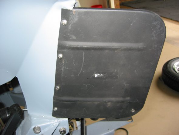
Right splash panel 1
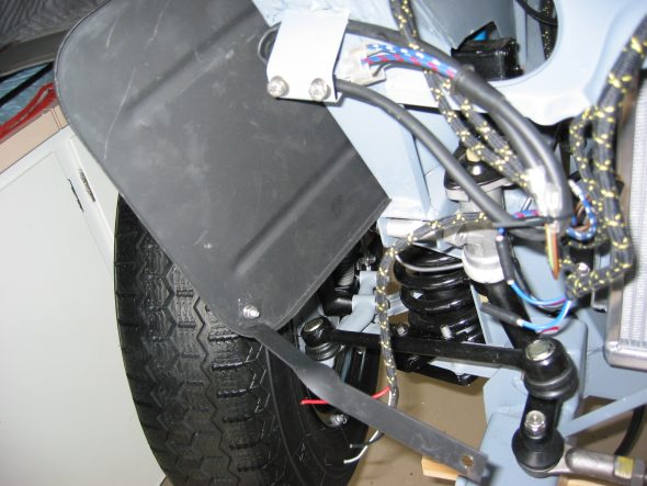
Right splash panel 2

Radiator Air Deflector – Installed radiator air deflector with two 5/16” x 5/8” bolts.
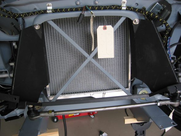
Air deflector 3
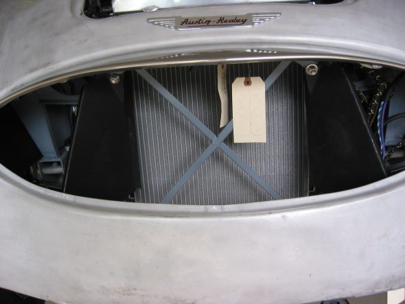
Air deflector 1

Bonnet Upright Brackets – Note the way they are mounted in the photos.
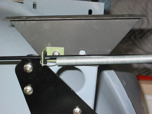
RH Bonnet opening brace 2
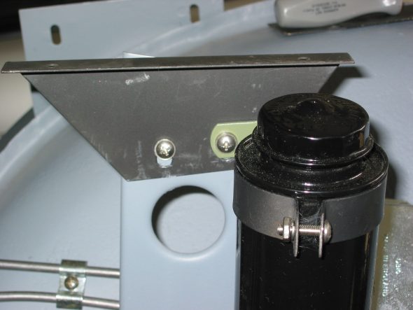
LH Bonnet opening brace 3

Front Wing Mounting Brackets – Installed left and right front wing support brackets using 4 1/4” x 3/4” hex head bolts.
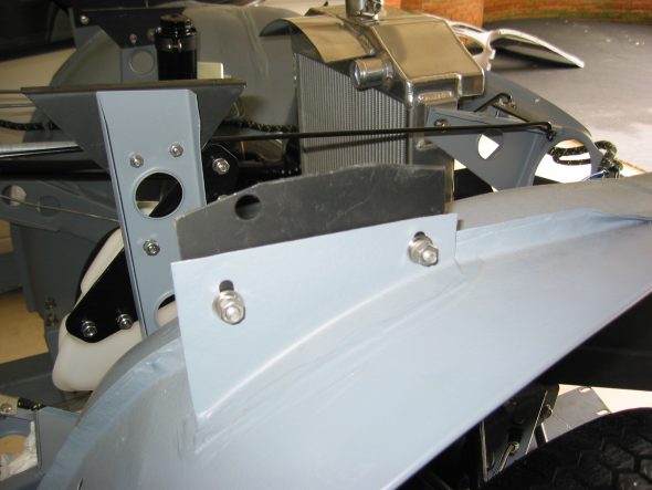
RH Shroud bracket 1
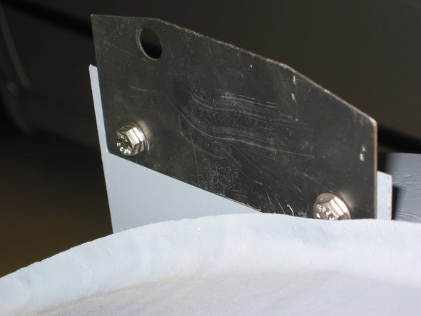
LH Shroud bracket 2

June 18, 2004

Rear Axle Revisited 

Differential – Installed the differential pumpkin and bearing caps in the differential casing. I will be installing the 3.44 crown and pinion in the car when it is drivable, but to get a rolling chassis I just put the old differential back in with no pinion gear. Fastened the differential to the axle and inserted the half shafts and tightened them down with the small locating flat head screws. Affixed the rear brake disc rotors and calipers fastened the hub extensions to the axle with the 5 locking hub nuts.

Installing the Rear Axle – After removing the fuel pump and the left bump box we “walked” the axle with the differential into the chassis and superstructure. I may have been able to leave the fuel pump had we had more access room on the right side of the car, but that wasn’t available. I then secured the axle with the Ubolts and the brackets for the tube shocks. The key here is to start each side loosely and then return to fully tighten each side. I never could get the tube shocks to align with the brackets and Udo Putzke thinks it may be because the Jule frame is slightly different than the original AH frame. To his credit he has agreed to make some longer shaft shocks at cost – great customer service!
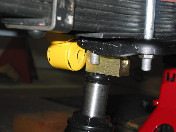
Bilsteins won’t align
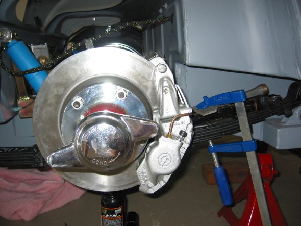
Spring Work

Rear Brake Hose – Added the new stainless braided brake hose between the brake line and the rear junction on the axle.
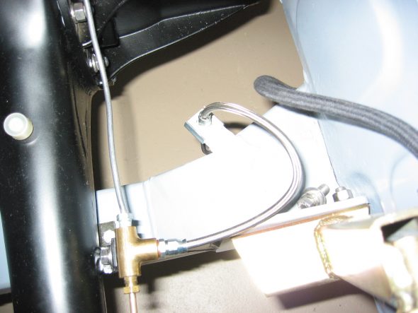
Stainless Rear Brake line

This work allowed me to put the car on the ground as a rolling chassis for the first time – a significant milestone. In honor of the occasion I stuck on two fenders and placed a seat in the interior for photos. All just for fun. It lasted ten minutes and then off came the wheels/tires and wings and then back up on jack stands for more work! The shiny bonnet is a sample paint color that I would ultimately not use.
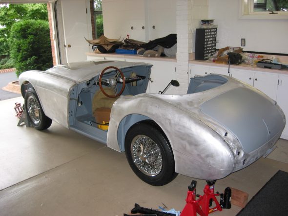
Four 0n the Floor 1
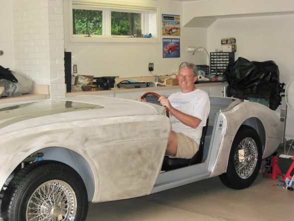
1st sitting
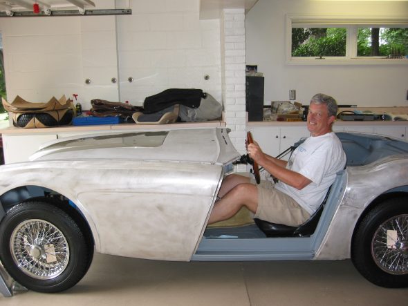
1st sitting 5

Driving Light and Tow Brackets – I received the front spotlight and tow hook brackets from Cape International and the rear bumperette (sprite) or Rally Car brackets and “bumpers.”  I discovered that Martin Jansen had not included the threaded tubes for the front bumper that go through the frame. Instead Martin’s are only on the outside of the frame rails which is fine for the bumper brackets, but the spotlight tow hook brackets also have one mounting hole on the inside of the frame rails. I located the holes on the inside of the rail with  3/8” drilled hole and will get Jeremy Turner to add threaded tubes later in the restoration. I also received Kilmartin panels for the frame rails that include the welded nuts for the anti-sway bar and I will give them to Jeremy as well.
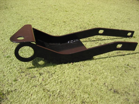
Driving light tow hook bracket
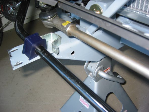
Driving Light frame Hole
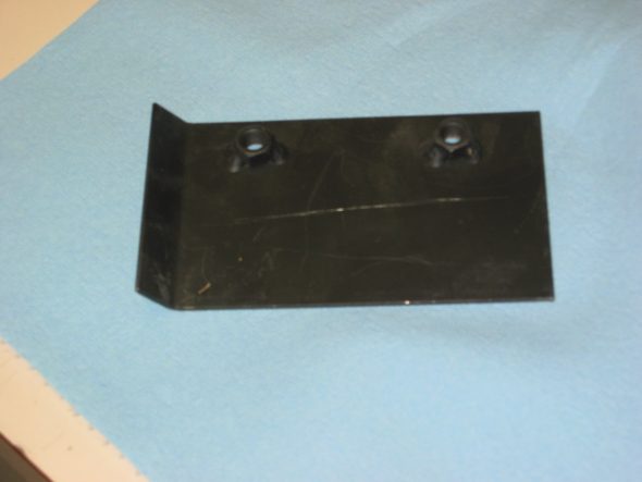
anti-sway bar frame bracket

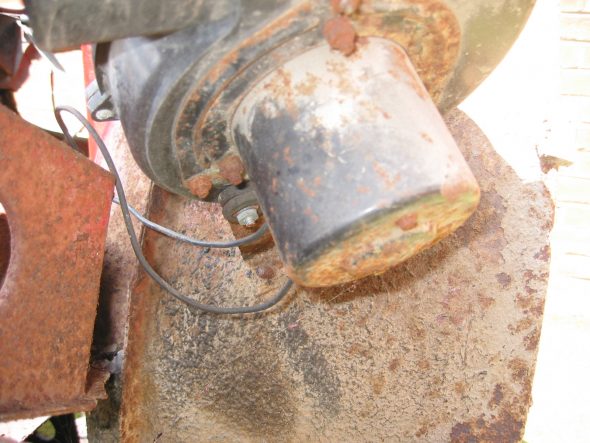
Horns – Started on the horn installation. The original horns for the Mark I are no longer available so I used the later version. The older horns must have been a little smaller in diameter, because the horns rubbed against the splash panels when connected with the brackets I had. I modified the brackets by adding a mounting hole and grinding off a bit of the bracket to “shift” the horns toward the center of the car. All of this seemed to work flawlessly, but once again I encountered a job that probably should have taken 10 minutes that ended up taking two hours. The horn wiring harness extensions provided by British Wiring were not needed so I crimped some new connectors on the wire in place of the original bullet connectors and attached them to the horns. The new horns were interesting – both brand new – one gloss black and one satin. I will have Jeremy repaint them.
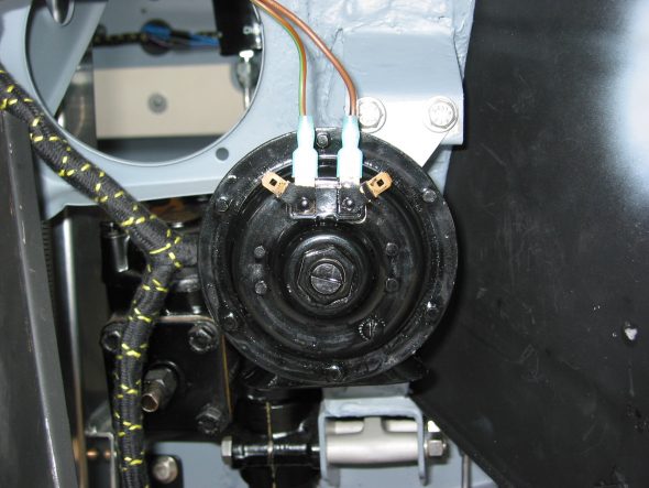
Horn install left

June 18, 2004

Fuel Sender Unit – Installed the fuel sender unit in the new aluminum fuel tank. The sender unit did not line up exactly as the original because the holes in the tank are not as they were in the steel tank. I sealed the sender unit with a new cork gasket and with Hylomar. Each of the small mounting screws received new copper washers.
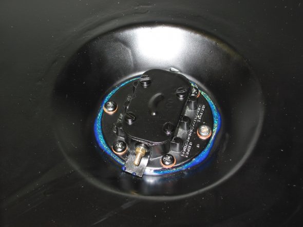
Fuel sender unit

New Fuel Tank – Secured the new fuel tank with the two securing straps which I had slightly lengthened to make the fit better. The securing straps fastened to the rear boot wall with brackets and clevis pins.
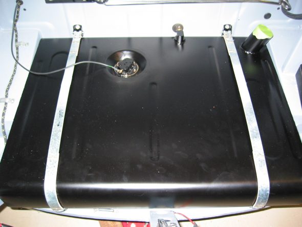
Aluminum Fuel Tank
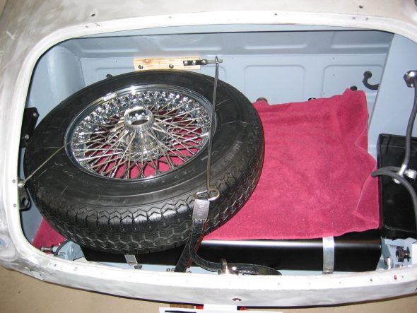
Spare tire fitment

Spare Tire Block and Bracket – Installed the new stainless steel spare tire bracket and tie down bar. I had to make a new vinyl covered block to fit on the back boot wall to accommodate the higher spare tire and the slight rise that was “built in” by Martin Jansen. Turned out pretty well. I actually used old naugahyde from my original reupholstery work on the car 20+ years ago!
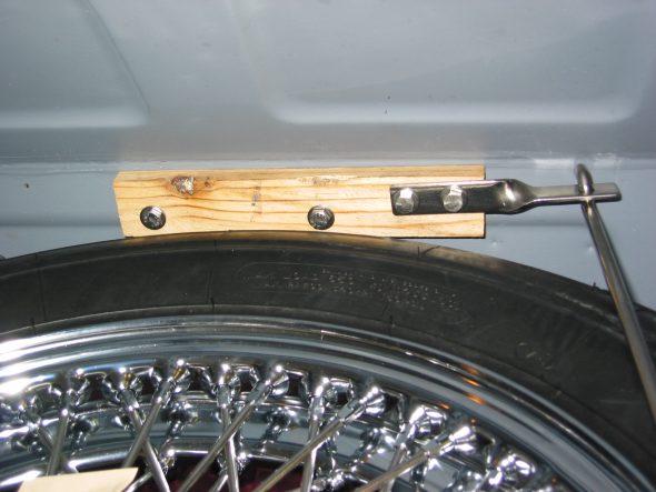
Spare tire bracket and block 1
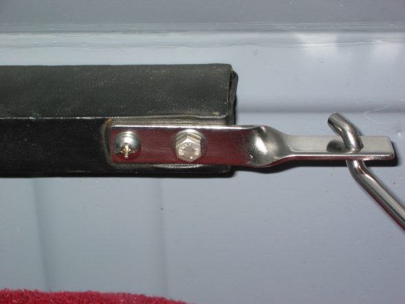
spare tire bracket and block 2
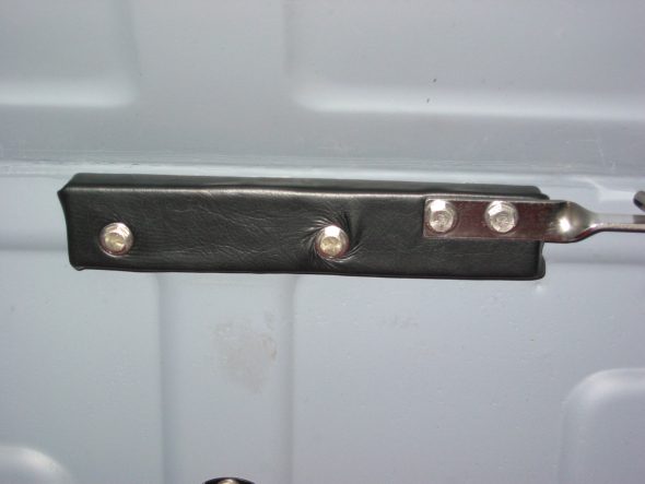
Spare Tire Block covering

Fuel Filler Pipe – Installed the fuel pipe rubber gasket on the rear shroud. Lightly smeared Vaseline on the lower section of the fuel pipe and pushed it through the gasket into the boot. The  Aston Cap is secured to the fuel tube with a threaded brass collar. David Nock advised that I should fasten the collar to the tube by reversing the ends and brazing the collar to the tube’s unfinished end. Then I cut off the old cap end to put into the rubber sleeve to connect to the tank neck.
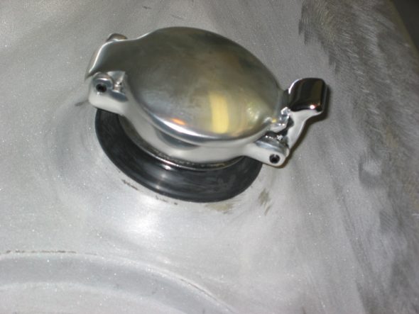
Aston filler Cap 1
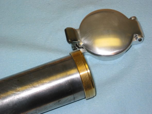
Aston threaded collar
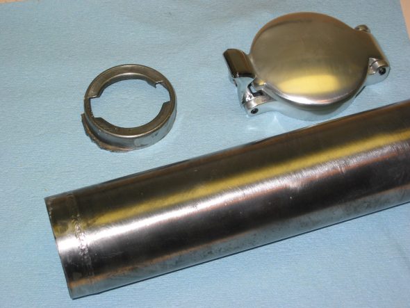
Fuel tube cut off
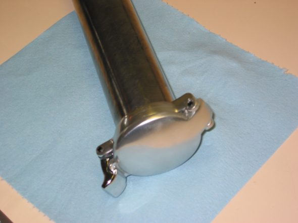
Aston fuel cap on pipe

Steering Cross Bar – After discovering that the new cross bar for the steering was for a BJ8 I ordered new ends and installed the original cross rod. I probably could have used the BJ8 bar but it looked like the original provided a little more adjustment which I think I needed.
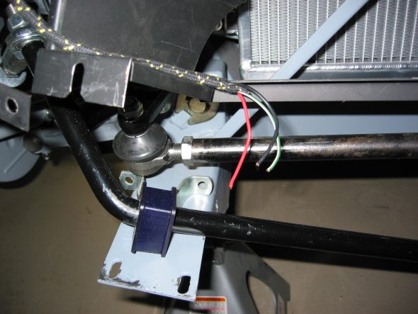
Cross rod right
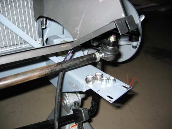
Cross rod left

 

Chapter 7 – Disassembly

Front Shroud

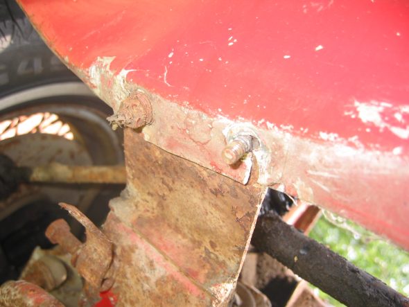
Removed five cross head drive screws at the rear of the bonnet. Three screws with nuts must be removed at the front of the shroud at the bonnet opening. Two cross head screws and nuts also attach the shroud to upright posts. A third bolt and nut holds the prop rod bracket. Five pop rivets were drilled out along the scuttle. Two additional rivets must be drilled out along each side and where the rubber seal attaches to the scuttle. Two bolts securing the shroud to each frame extension in the front must be loosened from their nuts. The shroud can then be released from the rear and pulled forward.

Prop Rod Bracket Removed

Rivet Removal

Front Shroud to Frame Mount

Shroud Removed 1

Shroud Removed 2

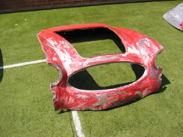
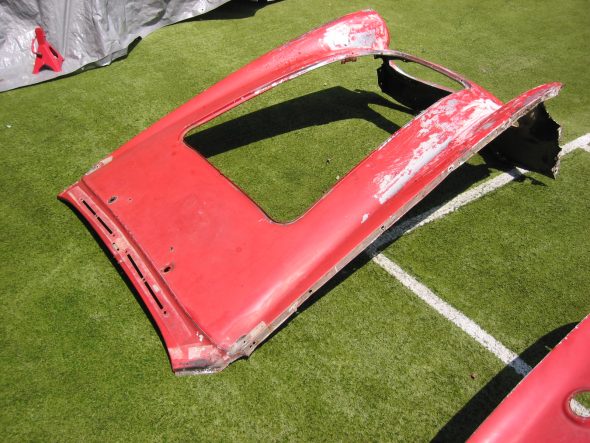
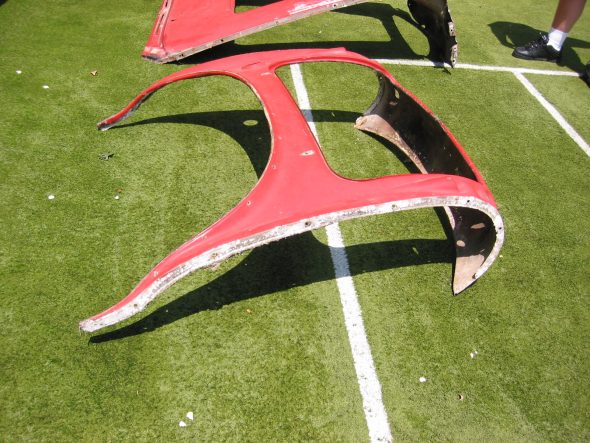
Rear Body Panel (shroud)

The rear body panel is released by first drilling out 19 rivets along the lower lip. Thirteen rivets must be drilled out that hold the body panel to the luggage compartment frame. Two or three rivets must be drilled out on the side of the rear body panel where the wing fastens to it. Four cross head screws and nuts must be removed from the top lip of the boot opening. The rear body panel can then be removed. Care must be taken to not bend the small front lip on the aluminum panel at the front points.

Rear Shroud 1

Rear Shroud 2

Doors

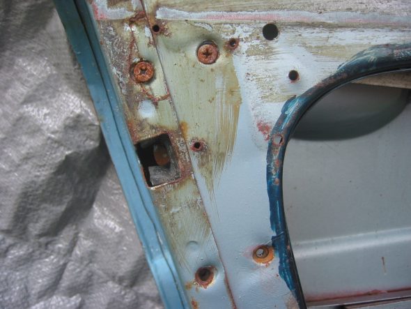
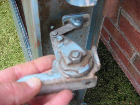
Removed three posidrive screws holding the interior door handle. Removed four posidrive screws at rear of door by handle. Removed opening mechanism. Loosen phillips head screw in door handle accessible when the door handle is pulled. 5/16” nut on the door handle screw. Loosen 5/16” nut on the screw on the back of the door handle – not easy to get to! Door handle can then be extracted from the door.

Interior Door Handle

Exterior Door Handle Fastener

Door Latch

Door Fasteners

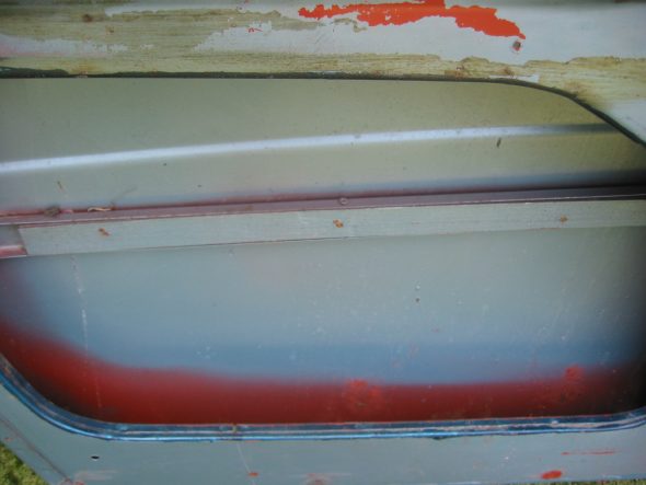
Removed side curtain bezel and retaining nut and chrome washer. Removed mid-door wood strip. One pozidrive screw on top center and two screws to the left and right on the bottom side. Removed the door strap (catch). 

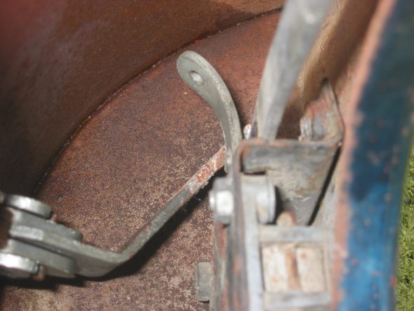
Door Catch Mechanism

Interior Door Trim Panel Wood

Door Opener Mechanism Orientation

Remove door hinges. Four bolts into a securing plate for each hinge. Drilled small indentation into the top bracket to recognize it. On reassembly of doors mount outside door handle first. Then install mechanism so that the action arm is in the proper place.

Door Catch at Door

Door Hinges

Aluminum Door Hinge

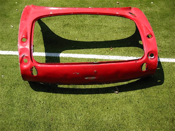
Boot Lid 

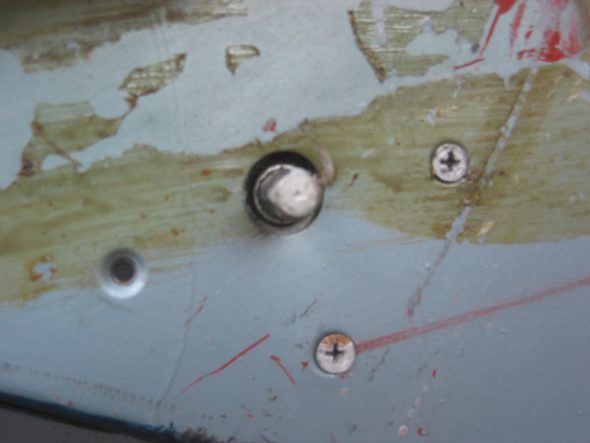
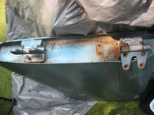
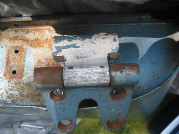
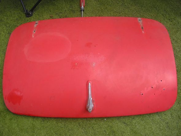
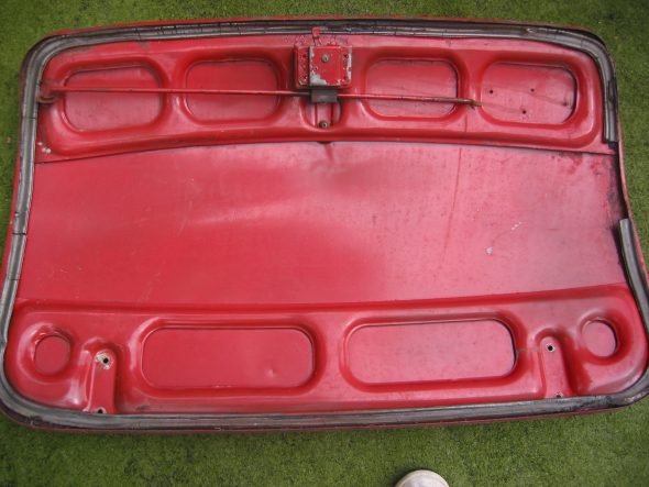
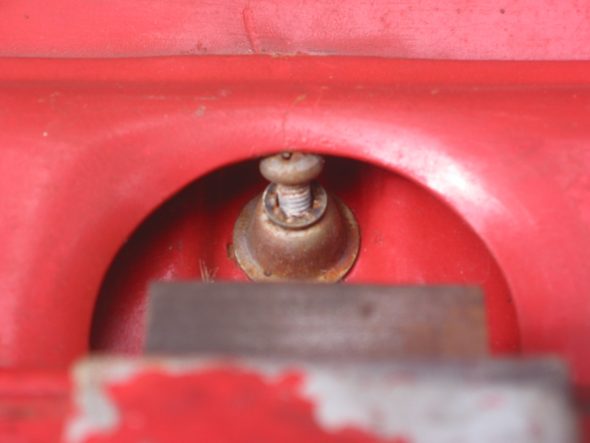
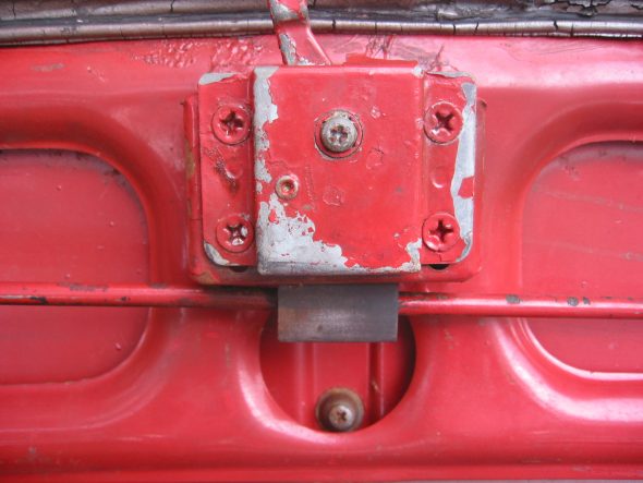
Removed two screws and cup washers securing the handle/lock. Remove four bolts/nuts holding the lock/catch mechanism. Remove one screw holding the locking mechanism post. Lock surface was painted as were the screw tops so it was installed when the car was painted. The chrome lock and handle were installed after the car was painted because the locking post screw was not painted.

Exterior Boot Lid

Interior Boot Lid

Boot Lock Handle

Boot Lock

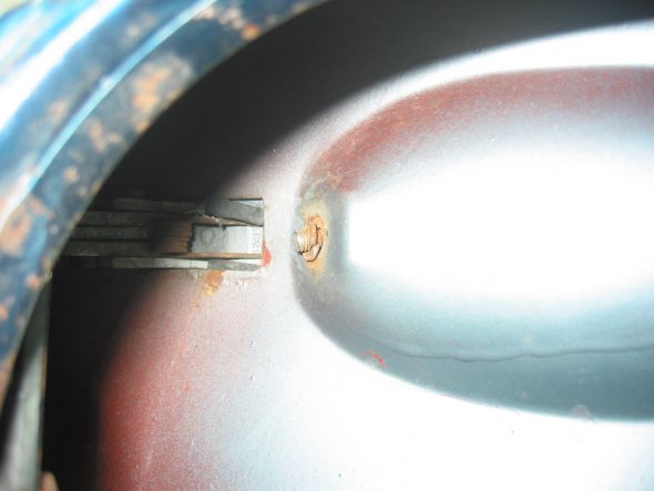
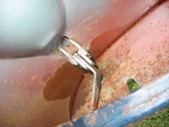
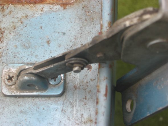
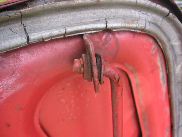
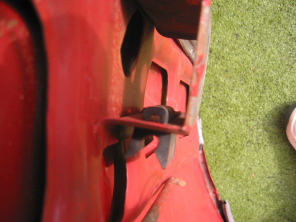
Removed the large cotter pin holding the rubber boot lid support rod. The rubber could then be removed as well. The head of he pin was located on the rod locator bracket side. A small cotter pin was removed from the support rod at the home bracket. The rubber grommet was then removed and the rod was detached.

Removed rubber gasket sealing boot lid.

Boot Rubber Seal

Boot Prop Rod Clasp

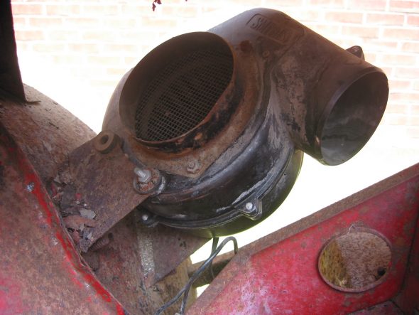
Heater Blower Assembly

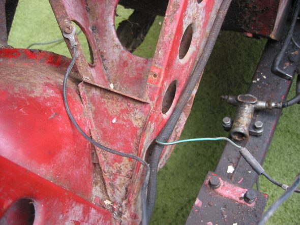
Removed four nuts on posts through rubber grommets. Black ground wire connects to the angle pillar. Power is through a green wire with a brown stripe that plugs into a rubber junction. 

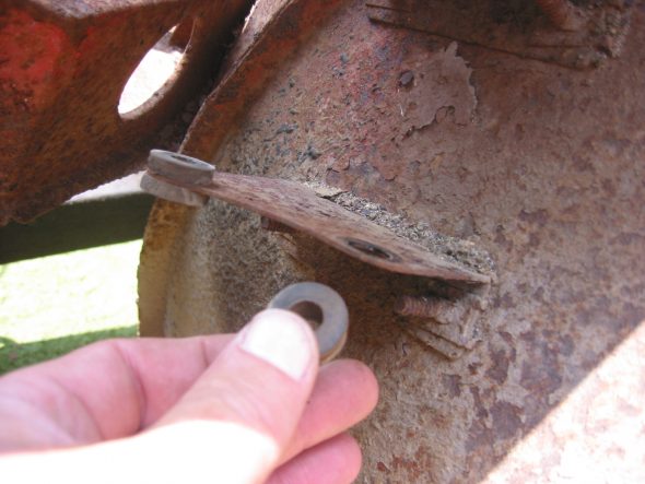
Removed the two heater blower mounting brackets. Two bolts each through wheel well arch. Large washers used on the tire side of the arch.

Smith’s Heater Blower

Blower Mounting Location on Frame Upright

Blower Mounting Rubber Grommets

Blower Motor Wiring Connections

July 28, 2002

Under Bonnet Components

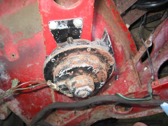
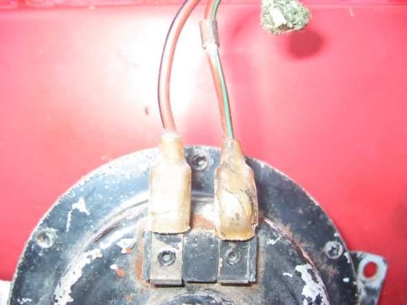
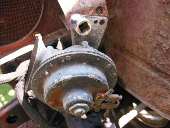
Horns – Located on the left and right of center under the front shroud. Each horn is secured with two bolts fastened into small steel threaded plates. I don’t believe my horns or brackets to be correct as one was mounted on the vertical shroud support like later cars.

Horn on Shroud Upright

Horn Wiring Connections

Proper Horn Location Under Front of Shroud

Horn Mounting Bracket

Steering Wheel

Steering Wheel


This is a diagram showing steering column components.

Steering Wheel Assembly

Steering Wheel Assembly

The disassembly procedure I followed is outlined below:

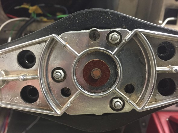
First I removed four slotted set screws from behind the steering wheel this enables the horn ring cover to be removed along with the horn push and return spring.

Horn Ring Assembly

Horn Ring Assembly

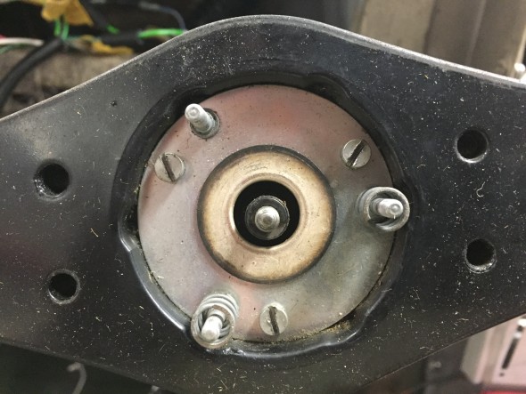
The horn ring assembly is held in place by three small nylock nuts (#6?) on studs. These nuts were removed and behind each nut was a nylon shouldered washer. The horn ring assembly is spring loaded so when the third nut is removed one needs to be careful not to lose the springs behind the assembly. After the three nuts and washers are loosened the horn ring can be lifted away.

Horn Assembly Springs on Studs

Horn Assembly Springs on Studs

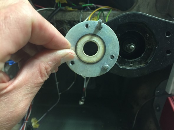
This reveals springs on two of the studs and a mounting plate held in place by three cheesehead machine screws. The springs were set aside and the three screws and slit washers were removed allowing the subsequent removal of the mounting plate with its three studs.

Horn Assembly Mounting Plate

Horn Assembly Mounting Plate

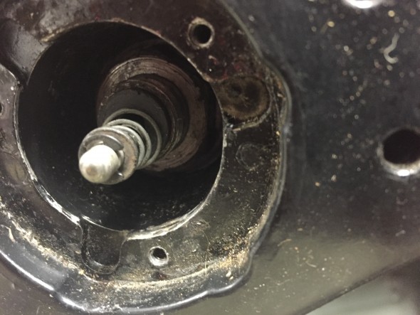
This revealed the horn button wire which contains the contact button, a spring, a small flat washer and a circlip holding the assembly together. a tubular black insulation piece is behind the wire assembly and slips into the shaft. It is NOT necessary to disassemble this horn contact wire in order to remove the steering wheel.

Horn Electrical Contact Wire, Retaining Clip, Washer and Spring

Horn Electrical Contact Wire, Retaining Clip, Washer and Spring

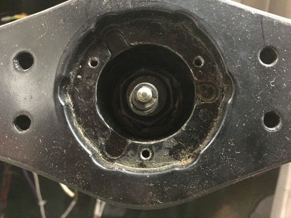
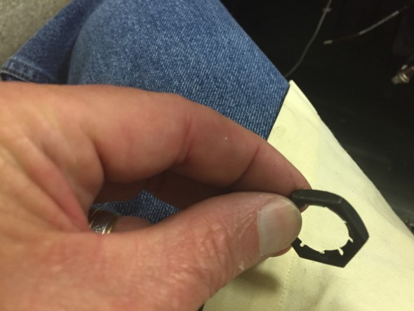
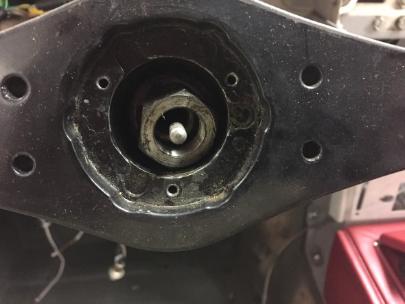
Also revealed was a locking Palnut on the steering shaft that was removed with a  15/16″ socket.

Steering Palnut on Shaft

Steering Palnut on Shaft

Steering Palnut Removed

Steering Palnut Removed

After removing the Palnut, the nut and special washer securing the steering wheel to the inner column shaft can be seen and removed. A 1  1/16″ socket was used.  The steering wheel could be then be removed from the shaft.

Steering Shaft Nut with Special flat washer

Steering Shaft Nut with Special flat washer

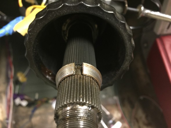
Steering Shaft Cone for Seating the steering wheel on the Shaft

Steering Shaft Cone for Seating the steering wheel on the Shaft

Care must be taken to not lose the two-piece split cone that seats the steering wheel on the shaft. These are revealed following removal of the steering wheel.